CN111532471A - A fully automatic packing machine - Google Patents
A fully automatic packing machineDownload PDFInfo
- Publication number
- CN111532471A CN111532471ACN202010434831.5ACN202010434831ACN111532471ACN 111532471 ACN111532471 ACN 111532471ACN 202010434831 ACN202010434831 ACN 202010434831ACN 111532471 ACN111532471 ACN 111532471A
- Authority
- CN
- China
- Prior art keywords
- plate
- driving
- fixed
- pressing
- connecting plate
- Prior art date
- Legal status (The legal status is an assumption and is not a legal conclusion. Google has not performed a legal analysis and makes no representation as to the accuracy of the status listed.)
- Pending
Links
- 238000012856packingMethods0.000titleclaimsabstractdescription24
- 238000003825pressingMethods0.000claimsabstractdescription76
- 238000005520cutting processMethods0.000claimsabstractdescription54
- 238000004806packaging method and processMethods0.000claimsabstractdescription16
- 238000004804windingMethods0.000claimsabstractdescription16
- 239000005060rubberSubstances0.000claimsabstractdescription15
- 239000000463materialSubstances0.000claimsdescription29
- 239000002390adhesive tapeSubstances0.000claimsdescription18
- 238000009434installationMethods0.000claims2
- 238000004519manufacturing processMethods0.000abstractdescription7
- 238000010586diagramMethods0.000description6
- 238000001125extrusionMethods0.000description6
- 230000007704transitionEffects0.000description3
- 239000004793PolystyreneSubstances0.000description2
- 239000003000extruded plasticSubstances0.000description2
- 238000000034methodMethods0.000description2
- 229920002223polystyrenePolymers0.000description2
- 230000009471actionEffects0.000description1
- 230000000903blocking effectEffects0.000description1
- 230000006835compressionEffects0.000description1
- 238000007906compressionMethods0.000description1
- 238000005260corrosionMethods0.000description1
- 230000007797corrosionEffects0.000description1
- 230000000694effectsEffects0.000description1
- 238000005187foamingMethods0.000description1
- 239000003292glueSubstances0.000description1
- 238000010438heat treatmentMethods0.000description1
- 230000006872improvementEffects0.000description1
- 238000009413insulationMethods0.000description1
- 239000004033plasticSubstances0.000description1
- 238000002360preparation methodMethods0.000description1
- 230000008569processEffects0.000description1
- 230000001681protective effectEffects0.000description1
- 239000002994raw materialSubstances0.000description1
- 238000009966trimmingMethods0.000description1
- 230000007306turnoverEffects0.000description1
- XLYOFNOQVPJJNP-UHFFFAOYSA-NwaterSubstancesOXLYOFNOQVPJJNP-UHFFFAOYSA-N0.000description1
Images


Classifications
- B—PERFORMING OPERATIONS; TRANSPORTING
- B65—CONVEYING; PACKING; STORING; HANDLING THIN OR FILAMENTARY MATERIAL
- B65B—MACHINES, APPARATUS OR DEVICES FOR, OR METHODS OF, PACKAGING ARTICLES OR MATERIALS; UNPACKING
- B65B11/00—Wrapping, e.g. partially or wholly enclosing, articles or quantities of material, in strips, sheets or blanks, of flexible material
- B65B11/02—Wrapping articles or quantities of material, without changing their position during the wrapping operation, e.g. in moulds with hinged folders
- B—PERFORMING OPERATIONS; TRANSPORTING
- B65—CONVEYING; PACKING; STORING; HANDLING THIN OR FILAMENTARY MATERIAL
- B65B—MACHINES, APPARATUS OR DEVICES FOR, OR METHODS OF, PACKAGING ARTICLES OR MATERIALS; UNPACKING
- B65B35/00—Supplying, feeding, arranging or orientating articles to be packaged
- B65B35/10—Feeding, e.g. conveying, single articles
- B65B35/24—Feeding, e.g. conveying, single articles by endless belts or chains
- B—PERFORMING OPERATIONS; TRANSPORTING
- B65—CONVEYING; PACKING; STORING; HANDLING THIN OR FILAMENTARY MATERIAL
- B65B—MACHINES, APPARATUS OR DEVICES FOR, OR METHODS OF, PACKAGING ARTICLES OR MATERIALS; UNPACKING
- B65B35/00—Supplying, feeding, arranging or orientating articles to be packaged
- B65B35/56—Orientating, i.e. changing the attitude of, articles, e.g. of non-uniform cross-section
- B—PERFORMING OPERATIONS; TRANSPORTING
- B65—CONVEYING; PACKING; STORING; HANDLING THIN OR FILAMENTARY MATERIAL
- B65B—MACHINES, APPARATUS OR DEVICES FOR, OR METHODS OF, PACKAGING ARTICLES OR MATERIALS; UNPACKING
- B65B61/00—Auxiliary devices, not otherwise provided for, for operating on sheets, blanks, webs, binding material, containers or packages
- B65B61/04—Auxiliary devices, not otherwise provided for, for operating on sheets, blanks, webs, binding material, containers or packages for severing webs, or for separating joined packages
- B65B61/06—Auxiliary devices, not otherwise provided for, for operating on sheets, blanks, webs, binding material, containers or packages for severing webs, or for separating joined packages by cutting
Landscapes
- Engineering & Computer Science (AREA)
- Mechanical Engineering (AREA)
- Package Closures (AREA)
Abstract
Description
Translated fromChinese技术领域technical field
本发明涉及挤塑板生产设备技术领域,具体是一种全自动打包机。The invention relates to the technical field of extrusion board production equipment, in particular to a fully automatic baler.
背景技术Background technique
挤塑板具有优良的保温隔热性,卓越的高强度抗压性,优质的憎水、防潮性,质地轻、使用方便,稳定性、防腐性好,经济实用适用于现代家装的应用,挤塑板生产时,一般需要先将原料进入到挤塑机,然后靠挤塑机进行加热加压发泡等步骤,最终使得呈类似熔融流动状态的聚苯乙烯从出口模具中挤出,并靠进一步挤压拓宽得到所需的板形。挤出成形后的聚苯乙烯长板经牵引装置牵引至后续工位完成切边和切断等工序,切割完成后,还需进行堆叠用胶带进行打包,现有的胶带打包都是采用人工进行打包,堆垛一起的挤塑板体积较大,采用人工对其进行胶带缠绕打包效率低,打包的效果也会参差不齐。The extruded board has excellent thermal insulation, excellent high-strength compression resistance, high-quality water repellency, moisture resistance, light texture, easy to use, good stability and corrosion resistance, economical and practical, suitable for modern home improvement applications, extrusion In the production of plastic panels, it is generally necessary to first enter the raw materials into the extruder, and then perform steps such as heating, pressurizing and foaming by the extruder, and finally extrude the polystyrene in a similar melt flow state from the outlet mold, and rely on the extruder. Further extrusion and widening are carried out to obtain the desired plate shape. The extruded polystyrene long board is pulled by the traction device to the subsequent station to complete the processes such as trimming and cutting. After the cutting is completed, it needs to be stacked and packed with tape. The existing tapes are packed manually. , The extruded plastic sheets stacked together are large in volume, and it is inefficient to wrap them with tape manually, and the packaging effect will be uneven.
发明内容SUMMARY OF THE INVENTION
本发明的目的在于提供一种全自动打包机,以解决背景技术中的技术问题。The purpose of the present invention is to provide a fully automatic baler to solve the technical problems in the background art.
为实现前述目的,本发明提供如下技术方案:For achieving the foregoing object, the present invention provides the following technical solutions:
一种全自动打包机,包括打包机架、第一传送带、第二传送带、设在打包机架内的胶带缠绕装置和胶带裁切装置,所述打包机架在第一传送带和第二传送带之间,所述第一传送带在打包机架前侧,所述打包机架为中空结构形成打包空间,所述胶带缠绕装置安装在打包机架内靠着第二传送带一侧,所述胶带裁切装置安装在靠着第一传送带一侧且与胶带缠绕装置位置相对;所述打包机架内的前后两侧分别安装有第一压合装置和第二压合装置,所述第一压合装置和第二压合装置分别对第一传送带和第二传送带上的产品进行按压固定。A fully automatic baler, comprising a baling frame, a first conveyor belt, a second conveyor belt, an adhesive tape winding device and an adhesive tape cutting device arranged in the baling frame, and the baling frame is located between the first conveyor belt and the second conveyor belt. The first conveyor belt is on the front side of the packing rack, the packing rack is a hollow structure to form a packing space, the tape winding device is installed in the packing rack against the side of the second conveyor belt, and the tape is cut The device is installed on the side of the first conveyor belt and is opposite to the tape winding device; a first pressing device and a second pressing device are respectively installed on the front and rear sides of the packaging frame, and the first pressing device and the second pressing device respectively press and fix the products on the first conveyor belt and the second conveyor belt.
所述胶带缠绕装置包括安装板、空心转轮、驱动空心转轮沿着空心转轮的轴心方向旋转运动的第一驱动组件和固定在空心转轮侧边的胶带放置盘,所述安装板上设有一通孔,沿着所述空心转轮的轴心的圆周方向等距设有数个支撑滚轮,所述支撑滚轮转动安装在安装板上,所述支撑滚轮在同一水平线上,所述空心转轮的内侧壁与支撑滚轮相接触,所述第一驱动组件包括第一驱动电机和转盘,所述第一驱动电机固定在安装板后侧,所述转盘与第一驱动电机的驱动轴连接,所述转盘与安装板上其中一个支撑滚轮位置对应,所述空心转轮在支撑滚轮和转盘之间,所述空心转轮的外侧壁与转盘相接触。The tape winding device includes a mounting plate, a hollow runner, a first drive assembly that drives the hollow runner to rotate along the axis of the hollow runner, and a tape placement plate fixed on the side of the hollow runner. There is a through hole on it, and several supporting rollers are arranged at equal distances along the circumferential direction of the axis of the hollow runner. The supporting rollers are rotatably installed on the mounting plate. The inner side wall of the runner is in contact with the supporting roller, the first drive assembly includes a first drive motor and a turntable, the first drive motor is fixed on the rear side of the mounting plate, and the turntable is connected with the drive shaft of the first drive motor , the position of the turntable corresponds to one of the support rollers on the mounting plate, the hollow runner is between the support roller and the turntable, and the outer side wall of the hollow runner is in contact with the turntable.
所述支撑滚轮包括连轴和滚轮,所述连轴穿过滚轮与安装板连接固定,所述滚轮转动连接在连轴上,所述滚轮上沿着滚轮外侧圆周方向设有一凹槽,所述凹槽内设有橡胶件,所述空心转轮在凹槽内,所述转盘外侧沿着转盘轴心的圆周方向套设有另一橡胶件。The supporting roller includes a connecting shaft and a roller, the connecting shaft is connected and fixed to the mounting plate through the roller, the roller is rotatably connected to the connecting shaft, and a groove is arranged on the roller along the outer circumferential direction of the roller, and the A rubber piece is arranged in the groove, the hollow runner is in the groove, and another rubber piece is sleeved on the outer side of the turntable along the circumferential direction of the axis of the turntable.
所述胶带放置盘包括支撑板、固定在支撑板上用于放置胶带的胶带辊和用于胶带导向的导辊,所述支撑板固定在空心转轮前侧。The adhesive tape placing tray includes a support plate, an adhesive tape roller fixed on the supporting plate for placing the adhesive tape and a guide roller for guiding the adhesive tape, and the supporting plate is fixed on the front side of the hollow runner.
所述胶带裁切装置包括支撑架、旋转架和驱动旋转架转动的第一驱动气缸,所述旋转架一侧通过一转轴与支撑架转动连接,所述支撑架固定在打包机架内,所述第一驱动气缸固定在打包机架上且在支撑架上方,所述第一驱动气缸的驱动轴与旋转架驱动连接,所述第一驱动气缸驱动旋转架沿着转轴的轴心进行翻转运动;所述旋转架上从上往下依次设有裁剪组件、接料组件和压料组件。The tape cutting device includes a support frame, a rotating frame and a first driving cylinder that drives the rotating frame to rotate. One side of the rotating frame is rotatably connected to the support frame through a rotating shaft, and the support frame is fixed in the packing frame, so The first driving cylinder is fixed on the packing frame and above the supporting frame, the driving shaft of the first driving cylinder is drivingly connected with the rotating frame, and the first driving cylinder drives the rotating frame to perform a turning movement along the axis of the rotating shaft ; A cutting assembly, a material receiving assembly and a pressing material assembly are arranged on the rotating frame in order from top to bottom.
所述旋转架包括从上往下依次平行设有第一连接板、第二连接板和第三连接板,所述第一连接板的左右两侧分别设有第一竖板和第二竖板,所述第一竖板与第二竖板横跨第一连接板和第三连接板且分别与其固定连接,所述第一竖板的外侧设有一凸块,所述第一驱动气缸的驱动轴与凸块连接,靠近所述第二竖板一侧设有一连杆,所述连杆穿过第一连接板、第二连接板和第三连接板且分别与第一连接板、第二连接板和第三连接板转动连接。The rotating frame includes a first connecting plate, a second connecting plate and a third connecting plate arranged in parallel from top to bottom, and the left and right sides of the first connecting plate are respectively provided with a first vertical plate and a second vertical plate , the first vertical plate and the second vertical plate straddle the first connecting plate and the third connecting plate and are respectively fixedly connected to them, the outer side of the first vertical plate is provided with a bump, the driving of the first driving cylinder The shaft is connected with the projection, and a connecting rod is arranged on the side close to the second vertical plate. The connecting rod passes through the first connecting plate, the second connecting plate and the third connecting plate and is respectively connected with the first connecting plate and the second connecting plate The connecting plate and the third connecting plate are rotatably connected.
所述裁剪组件包括裁切板、固定在裁切板一端的切刀和第二驱动气缸,所述裁切板的另一端设有第一套筒,所述第一套筒套设在连杆上且与连杆转动连接,所述裁切板在第一连接板下方,所述第二驱动气缸固定在第一连接板上方且与裁切板驱动连接,所述切刀的上方设有一防静电刷,所述防静电刷与裁切板固定连接;所述接料组件包括第三驱动气缸、推板和接料棒,所述第三驱动气缸固定在第二连接板上,所述推板的后端设有第二套筒与连杆转动连接,所述推板的前端与接料棒位置相对应,所述推板在裁切板下方且在第二连接板上方,所述接料棒水平方向垂直连接在第二竖板的一侧,胶带在进行裁切前粘贴在所述接料棒上便于下轮打包进行粘贴,所述推板上设有一安装块,所述第三驱动气缸与安装块驱动连接;所述压料组件包括压料板、固定在压料板后侧的压块和第四驱动气缸,所述压料板的后侧设有第三套筒与连杆转动连接,所述压料板在压第三连接板上方,所述第四驱动气缸固定在第三连接板上,所述第四驱动气缸与压料板驱动连接。The cutting assembly includes a cutting board, a cutter fixed at one end of the cutting board, and a second driving cylinder, the other end of the cutting board is provided with a first sleeve, and the first sleeve is sleeved on the connecting rod. The cutting board is below the first connecting board, the second driving cylinder is fixed above the first connecting board and is drivingly connected with the cutting board, and a protective plate is provided above the cutting knife. an electrostatic brush, the anti-static brush is fixedly connected with the cutting board; the material receiving assembly includes a third driving cylinder, a push plate and a material receiving rod, the third driving cylinder is fixed on the second connecting plate, the pushing The rear end of the plate is provided with a second sleeve for rotational connection with the connecting rod, the front end of the push plate corresponds to the position of the receiving rod, the push plate is below the cutting plate and above the second connecting plate, the connecting The material bar is vertically connected to one side of the second vertical plate in the horizontal direction, and the tape is pasted on the material receiving bar before cutting, so as to facilitate the packaging and pasting of the lower wheel, the push plate is provided with a mounting block, and the third The driving cylinder is drivingly connected with the mounting block; the material pressing assembly includes a pressing plate, a pressing block fixed on the rear side of the pressing plate and a fourth driving cylinder, and the rear side of the pressing plate is provided with a third sleeve and connecting The rod is connected in rotation, the pressing plate is above the third connecting plate, the fourth driving cylinder is fixed on the third connecting plate, and the fourth driving cylinder is drivingly connected with the pressing plate.
所述第一压合装置和第二压合装置结构相同,所述第一压合装置与第二压合装置分别在第一传送带和第二传送带上方,所述第一压合装置包括第五驱动气缸和压合板,所述第五驱动气缸固定在打包机架上,所述第五驱动气缸的驱动轴与压合板驱动连接,所述第五驱动气缸驱动压合板沿着Z轴方向上下运动。The first pressing device and the second pressing device have the same structure, the first pressing device and the second pressing device are respectively above the first conveyor belt and the second conveyor belt, and the first pressing device includes a fifth Drive the cylinder and the pressing plate, the fifth driving cylinder is fixed on the packing frame, the driving shaft of the fifth driving cylinder is drivingly connected with the pressing plate, and the fifth driving cylinder drives the pressing plate to move up and down along the Z-axis direction .
所述第一传送带和第二传送带上分别设有至少一组相同结构的对中装置,所述对中装置包括左对中组件和右对中组件,所述左对中组件和右对中组件结构相同且对称设置在第一传送带或第二传送带的左右两侧,所述左对中组件包括安装架、第六驱动气缸和对中板,所述安装架固定在第一传送带或第二传送带上,所述第六驱动气缸固定在安装架上,所述第六驱动气缸与对中板驱动连接,所述第六驱动气缸驱动对中板沿着X轴方向运动。The first conveyor belt and the second conveyor belt are respectively provided with at least one set of centering devices with the same structure, the centering devices include left centering components and right centering components, the left centering components and the right centering components The structure is the same and symmetrically arranged on the left and right sides of the first conveyor belt or the second conveyor belt. The left centering assembly includes a mounting frame, a sixth driving cylinder and a centering plate, and the mounting frame is fixed on the first conveyor belt or the second conveyor belt. The sixth driving cylinder is fixed on the mounting frame, the sixth driving cylinder is drivingly connected with the centering plate, and the sixth driving cylinder drives the centering plate to move along the X-axis direction.
与现有技术相比,本发明提供的一种全自动打包机,通过空心转轮带动胶带绕着传送带上的挤塑板外侧进行缠绕打包,再通过裁切组件对胶带进行裁切,实现自动化的生产,减少人工操作时间和作业人员的数量,保证打包质量的统一性,提高了生产效率。Compared with the prior art, the fully automatic baler provided by the present invention uses a hollow wheel to drive the tape to wrap around the outside of the extruded board on the conveyor belt for wrapping and packaging, and then cuts the tape through a cutting assembly to realize automation. It can reduce the manual operation time and the number of operators, ensure the uniformity of packaging quality, and improve the production efficiency.
附图说明Description of drawings
图1:一种全自动打包机立体结构示意图;Figure 1: A schematic diagram of the three-dimensional structure of a fully automatic baler;
图2:一种全自动打包机主视图;Figure 2: Front view of a fully automatic baler;
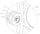
图3:胶带缠绕装置结构示意图;Figure 3: Schematic diagram of the structure of the tape winding device;
图4:图3的A处放大图;Figure 4: Enlarged view of part A of Figure 3;
图5:胶带缠绕装置工作原理示意图;Figure 5: Schematic diagram of the working principle of the tape winding device;
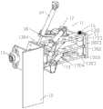
图6:胶带裁切装置立体结构示意图;Figure 6: Schematic diagram of the three-dimensional structure of the tape cutting device;
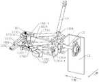
图7:胶带裁切装置另一方向立体结构示意图;Figure 7: Schematic diagram of the three-dimensional structure of the tape cutting device in the other direction;
图8:胶带裁切装置俯视图;Figure 8: Top view of tape cutting device;
图9:胶带裁切装置侧视图;Figure 9: Side view of tape cutting device;
图10:第一压合装置和第二压合装置结构示意图。Figure 10: Schematic diagram of the structure of the first pressing device and the second pressing device.
具体实施方式Detailed ways
下面将结合本发明实施例中的附图,对本发明实施例中的技术方案进行清楚、完整地描述。The technical solutions in the embodiments of the present invention will be clearly and completely described below with reference to the accompanying drawings in the embodiments of the present invention.
具体实施例1:请参阅图1到图10,本发明实施例中,一种全自动打包机,一种全自动打包机,包括打包机架1、第一传送带2、第二传送带3、设在打包机架1内的胶带缠绕装置4和胶带裁切装置11,所述打包机架1在第一传送带2和第二传送带3之间,所述第一传送带2在打包机架1前侧,所述打包机架1为中空结构形成打包空间,所述胶带缠绕装置4安装在打包机架1内靠着第二传送带3一侧,所述胶带裁切装置11安装在靠着第一传送带2一侧且与胶带缠绕装置4位置相对;所述打包机架1内的前后两侧分别安装有第一压合装置20和第二压合装置21,所述第一压合装置20和第二压合装置21分别对第一传送带2和第二传送带3上的产品进行按压固定。Specific embodiment 1: Please refer to FIG. 1 to FIG. 10. In the embodiment of the present invention, a fully automatic baler, a fully automatic baler, includes a
所述胶带缠绕装置4包括安装板5、空心转轮6、驱动空心转轮6沿着空心转轮6的轴心方向旋转运动的第一驱动组件9和固定在空心转轮6侧边的胶带放置盘8,所述安装板5上设有一通孔501,沿着所述空心转轮6的轴心的圆周方向等距设有数个支撑滚轮7,所述支撑滚轮7转动安装在安装板5上,所述支撑滚轮7在同一水平线上,所述空心转轮6的内侧壁与支撑滚轮7相接触,所述第一驱动组件9包括第一驱动电机901和转盘902,所述第一驱动电机901固定在安装板5后侧,所述转盘902与第一驱动电机901的驱动轴连接,所述转盘902与安装板5上其中一个支撑滚轮7位置对应,所述空心转轮6在支撑滚轮7和转盘902之间,所述空心转轮6的外侧壁与转盘902相接触。所述空心转轮6下方安装有过渡辊10用于输送挤塑板,所述过渡辊10在第一传送带2和第二传送带3之间,所述过渡辊10固定在打包机架1上。The tape winding device 4 includes a
所述支撑滚轮7包括连轴701和滚轮702,所述连轴701穿过滚轮702与安装板5连接固定,所述滚轮702转动连接在连轴701上,所述滚轮702上沿着滚轮702外侧圆周方向设有一凹槽702-1,所述凹槽702-1内设有橡胶件703,所述空心转轮6在凹槽702-1内,所述转盘902外侧沿着转盘902轴心的圆周方向套设有另一橡胶件903。通过摩擦力的作用,当所述第一驱动电机901驱动转盘902顺时针旋转运动的时候,所述转盘902的外侧与空心转轮6接触挤压,所述空心转轮6在支撑滚轮7的凹槽702-1内逆时针方向旋转,从而带动胶带放置盘8同时进行旋转。The
所述胶带放置盘8包括支撑板801、固定在支撑板801上用于放置胶带的胶带辊802和用于胶带导向的导辊803,所述支撑板801固定在空心转轮6前侧。在打包作业前,所述胶带辊802上的胶带绕过导辊803进入胶带裁切装置11且贴合在内进行准备作业。The
所述胶带裁切装置11包括支撑架12、旋转架13和驱动旋转架13转动的第一驱动气缸14,所述旋转架13一侧通过一转轴15与支撑架12转动连接,所述支撑架12固定在打包机架1内,所述第一驱动气缸14固定在打包机架1上且在支撑架12上方,所述第一驱动气缸14的驱动轴与旋转架13驱动连接,所述第一驱动气缸14驱动旋转架13沿着转轴15的轴心进行翻转运动;所述旋转架13上从上往下依次设有裁剪组件17、接料组件18和压料组件19,所述裁剪组件17、接料组件18和压料组件19分别与旋转架13转动连接。The
所述旋转架13包括从上往下依次平行设有第一连接板1301、第二连接板1302和第三连接板1303,所述第一连接板1301的左右两侧分别设有第一竖板1304和第二竖板1305,所述第一竖板1304与第二竖板1305横跨第一连接板1301和第三连接板1303且分别与其固定连接,所述第一竖板1304的外侧设有一凸块1304-1,所述第一驱动气缸14的驱动轴与凸块1304-1连接,靠近所述第二竖板1305一侧设有一连杆16,所述连杆16穿过第一连接板1301、第二连接板1302和第三连接板1303,所述连杆16的上下两端分别与第一连接板1301和第三连接板1303固定连接。The rotating
所述裁剪组件17包括裁切板1701、固定在裁切板1701一端的切刀1702和第二驱动气缸1704,所述裁切板1701的另一端设有第一套筒1703,所述第一套筒1703套设在连杆16上且与连杆16转动连接,所述裁切板1701在第一连接板1301下方,所述第二驱动气缸1704固定在第一连接板1301上方且与裁切板1701驱动连接,所述第二驱动气缸1704驱动裁切板1701往第一传送带2方向移动进行胶带的裁切,所述切刀1702的上方设有一防静电刷1705,所述防静电刷1705与裁切板1701固定连接;所述接料组件18包括第三驱动气缸1804、推板1801和接料棒1802,所述第三驱动气缸1804固定在第二连接板1302上,所述推板1801的后端设有第二套筒1803与连杆16转动连接,所述推板1801的前端与接料棒1802位置相对应,所述推板1801在裁切板1701下方且在第二连接板1302上方,所述接料棒1802水平方向垂直连接在第二竖板1305的一侧,胶带在进行裁切前粘贴在所述接料棒1802上便于下轮打包进行粘贴,所述推板1801上设有一安装块1801-1,所述第三驱动气缸1804与安装块1801-1驱动连接,所述第三驱动气缸1804驱动推板1801往接料棒1802方向运动,所述推板1801与接料棒1802接触将胶带压合粘贴在接料棒1802上;所述压料组件19包括压料板1901、固定在压料板1901后侧的压块1902和第四驱动气缸1904,所述压料板1901的后侧设有第三套筒1903与连杆16转动连接,所述压料板1901在压第三连接板1303上方,所述第四驱动气缸1904固定在第三连接板1303上,所述第四驱动气缸1904与压料板1901驱动连接。The cutting
所述第一压合装置20和第二压合装置21结构相同,所述第一压合装置20与第二压合装置21分别在第一传送带2和第二传送带3上方,所述第一压合装置20包括第五驱动气缸2001和压合板2002,所述第五驱动气缸2001固定在打包机架1上,所述第五驱动气缸2001的驱动轴与压合板2002驱动连接,所述第五驱动气缸2001驱动压合板2002沿着Z轴方向上下运动。The first
所述第一传送带2和第二传送带3上分别设有至少一组相同结构的对中装置22,所述对中装置22包括左对中组件2201和右对中组件2202,所述左对中组件2201和右对中组件2202结构相同且对称设置在第一传送带2或第二传送带3的左右两侧,所述左对中组件2201包括安装架2201-1、第六驱动气缸2201-2和对中板2201-3,所述安装架固定在第一传送带2或第二传送带3上,所述第六驱动气缸2201-2固定在安装架2201-1上,所述第六驱动气缸2201-2与对中板2201-3驱动连接,所述第六驱动气缸2201-2驱动对中板2201-3沿着X轴方向运动。The
工作流程:堆垛后的挤塑板经第一传送带2输送至打包机架1内,第一传送带2上的对中装置22对挤塑板进行对中整理,挤塑板的一端移送至第二传送带3上至设定距离后,第一压合装置20和第二压合装置21向下运动压合挤塑板,压力组件上的压块1902在第四气缸的驱动下往挤塑板方向移动,将胶带往挤塑板方向按压,将胶带的一端粘合在挤塑板的一侧,空心转轮6在第一驱动电机901的驱动下旋转运动,同时带动胶带逆时针方向缠绕着挤塑板进行粘合,当胶带缠绕一圈接近压块1902位置时,压块1902复位,同时第一驱动气缸14拉动旋转架13向上旋转,所述旋转架13绕着转轴15的轴心向上翻转,远离胶带位置,避免接料棒1802对其胶带形成阻挡,胶带继续绕着挤塑板进行缠绕粘贴,当胶带缠绕到设定的圈数后,旋转架13向下翻转进行复位,胶带旋转至接料棒1802位置后粘合在接料棒1802上,同时第三驱动气缸1804驱动推板1801往接料棒1802方向移动,将胶带进一步压合在接料棒1802上,第二驱动气缸1704驱动裁切板1701往胶带方向移动进行胶带的切除,第一压合装置20和第二压合装置21复位,如此完成一次胶带缠绕,挤塑板继续往第二输送带方向移动直至下一打包位置,进行相同的缠胶打包作业,可根据生产需要确定对挤塑板不同位置进行胶带缠绕打包。Workflow: The stacked extruded boards are transported to the
与现有技术相比,本发明提供的一种全自动打包机,通过空心转轮带动胶带绕着传送带上的挤塑板外侧进行缠绕打包,再通过裁切组件对胶带进行裁切,实现自动化的生产,减少人工操作时间和作业人员的数量,保证打包质量的统一性,提高了生产效率。Compared with the prior art, the fully automatic baler provided by the present invention uses a hollow wheel to drive the tape to wrap around the outside of the extruded board on the conveyor belt for wrapping and packaging, and then cuts the tape through a cutting assembly to realize automation. It can reduce the manual operation time and the number of operators, ensure the uniformity of packaging quality, and improve the production efficiency.
对于本领域技术人员而言,显然本发明不限于前述示范性实施例的细节,而且在不背离本发明的精神或基本特征的情况下,能够以其他的具体形式实现本发明。因此,无论从哪一点来看,均应将实施例看作是示范性的,而且是非限制性的,本发明的范围由所附权利要求而不是前述说明限定,因此旨在将落在权利要求的等同要件的含义和范围内的所有变化囊括在本发明内。不应将权利要求中的任何附图标记视为限制所涉及的权利要求。It will be apparent to those skilled in the art that the present invention is not limited to the details of the foregoing exemplary embodiments, but that the present invention may be embodied in other specific forms without departing from the spirit or essential characteristics of the invention. Accordingly, the embodiments are to be regarded in all respects as illustrative and not restrictive, the scope of the invention being defined by the appended claims rather than the foregoing description, and are therefore intended to fall within the scope of the appended claims. All changes within the meaning and scope of the equivalents of , are included in the present invention. Any reference signs in the claims shall not be construed as limiting the involved claim.
此外,应当理解,虽然本说明书按照实施方式加以描述,但并非每个实施方式仅包含一个独立的技术方案,说明书的这种叙述方式仅仅是为清楚起见,本领域技术人员应当将说明书作为一个整体,各实施例中的技术方案也可以经适当组合,形成本领域技术人员可以理解的其他实施方式。In addition, it should be understood that although this specification is described in terms of embodiments, not each embodiment only includes an independent technical solution, and this description in the specification is only for the sake of clarity, and those skilled in the art should take the specification as a whole , the technical solutions in each embodiment can also be appropriately combined to form other implementations that can be understood by those skilled in the art.
Claims (9)
Priority Applications (1)
| Application Number | Priority Date | Filing Date | Title |
|---|---|---|---|
| CN202010434831.5ACN111532471A (en) | 2020-05-21 | 2020-05-21 | A fully automatic packing machine |
Applications Claiming Priority (1)
| Application Number | Priority Date | Filing Date | Title |
|---|---|---|---|
| CN202010434831.5ACN111532471A (en) | 2020-05-21 | 2020-05-21 | A fully automatic packing machine |
Publications (1)
| Publication Number | Publication Date |
|---|---|
| CN111532471Atrue CN111532471A (en) | 2020-08-14 |
Family
ID=71974169
Family Applications (1)
| Application Number | Title | Priority Date | Filing Date |
|---|---|---|---|
| CN202010434831.5APendingCN111532471A (en) | 2020-05-21 | 2020-05-21 | A fully automatic packing machine |
Country Status (1)
| Country | Link |
|---|---|
| CN (1) | CN111532471A (en) |
Cited By (10)
| Publication number | Priority date | Publication date | Assignee | Title |
|---|---|---|---|---|
| CN112173203A (en)* | 2020-10-08 | 2021-01-05 | 安徽恒硕纺织品有限公司 | Automatic packing apparatus is rolled up to spinning material |
| CN113148271A (en)* | 2021-04-01 | 2021-07-23 | 潍坊职业学院 | Colored ribbon packaging machine |
| CN113682562A (en)* | 2021-08-31 | 2021-11-23 | 蚌埠市高远光电有限公司 | LCD liquid crystal display's partial shipment package mechanism |
| CN114162387A (en)* | 2021-11-30 | 2022-03-11 | 浙江工商职业技术学院 | A feeding and swinging device |
| CN114620254A (en)* | 2022-04-06 | 2022-06-14 | 安徽省烟草公司滁州市公司 | Transverse and longitudinal film wrapping packaging method for strip cigarette |
| CN116986086A (en)* | 2023-05-19 | 2023-11-03 | 苏州市协和药业有限公司 | Coiling case sealer |
| CN117141826A (en)* | 2023-09-19 | 2023-12-01 | 山东中汇彩钢有限公司 | Device and method for trimming and packaging color steel plate |
| CN117141796A (en)* | 2023-09-15 | 2023-12-01 | 深圳市嘉铭半导体科技有限公司 | Packaging equipment |
| CN118877279A (en)* | 2024-08-27 | 2024-11-01 | 马鞍山钢铁股份有限公司 | Device and method for eliminating air in steel coil coating of automatic packaging line |
| CN120397372A (en)* | 2025-07-01 | 2025-08-01 | 泛亚电缆有限公司 | An automatic cutting and laminating device for cable packaging tape |
Citations (14)
| Publication number | Priority date | Publication date | Assignee | Title |
|---|---|---|---|---|
| CN101269703A (en)* | 2008-03-25 | 2008-09-24 | 罗嘉航 | Horizontal thin film winding packing machine |
| JP4627598B2 (en)* | 2001-02-05 | 2011-02-09 | シグノード株式会社 | Bundling device |
| CN202115722U (en)* | 2011-06-10 | 2012-01-18 | 正兴车轮集团有限公司 | Wheel winding machine |
| CN205686654U (en)* | 2016-08-30 | 2016-11-16 | 佛山市九一自动化科技有限公司 | Multitube packing wind |
| CN205837274U (en)* | 2016-05-18 | 2016-12-28 | 苏州工业职业技术学院 | Nursery stock winding-packing machine |
| CN205972036U (en)* | 2016-08-29 | 2017-02-22 | 广州国诺自动化设备有限公司 | Automatic case sealer gummed paper mechanism of twining of ring type |
| CN107010276A (en)* | 2016-01-27 | 2017-08-04 | 广州国诺自动化设备有限公司 | A kind of revolving ring type automatic winding cartoning sealing machine |
| CN206615422U (en)* | 2017-02-27 | 2017-11-07 | 苏州工业职业技术学院 | Thin film winding machine |
| CN207725682U (en)* | 2017-09-28 | 2018-08-14 | 昆山精讯电子技术有限公司 | Adhesive tape winds cutting means |
| CN108569430A (en)* | 2018-04-27 | 2018-09-25 | 江苏瑞德兰自动化科技有限公司 | A kind of Full-automatic tire wrapping machine |
| CN110342005A (en)* | 2019-08-26 | 2019-10-18 | 佛山市帝益机械科技有限公司 | A kind of automation twin shaft winding package equipment |
| CN209870820U (en)* | 2019-03-29 | 2019-12-31 | 江苏信息职业技术学院 | Novel automatic baling equipment of anchor ring |
| CN210191894U (en)* | 2019-06-28 | 2020-03-27 | 佛山市联澜自动化科技有限公司 | Winding device is tied up to tubular product |
| CN110963111A (en)* | 2019-12-18 | 2020-04-07 | 李国强 | Wire film winding device for wire coil |
- 2020
- 2020-05-21CNCN202010434831.5Apatent/CN111532471A/enactivePending
Patent Citations (14)
| Publication number | Priority date | Publication date | Assignee | Title |
|---|---|---|---|---|
| JP4627598B2 (en)* | 2001-02-05 | 2011-02-09 | シグノード株式会社 | Bundling device |
| CN101269703A (en)* | 2008-03-25 | 2008-09-24 | 罗嘉航 | Horizontal thin film winding packing machine |
| CN202115722U (en)* | 2011-06-10 | 2012-01-18 | 正兴车轮集团有限公司 | Wheel winding machine |
| CN107010276A (en)* | 2016-01-27 | 2017-08-04 | 广州国诺自动化设备有限公司 | A kind of revolving ring type automatic winding cartoning sealing machine |
| CN205837274U (en)* | 2016-05-18 | 2016-12-28 | 苏州工业职业技术学院 | Nursery stock winding-packing machine |
| CN205972036U (en)* | 2016-08-29 | 2017-02-22 | 广州国诺自动化设备有限公司 | Automatic case sealer gummed paper mechanism of twining of ring type |
| CN205686654U (en)* | 2016-08-30 | 2016-11-16 | 佛山市九一自动化科技有限公司 | Multitube packing wind |
| CN206615422U (en)* | 2017-02-27 | 2017-11-07 | 苏州工业职业技术学院 | Thin film winding machine |
| CN207725682U (en)* | 2017-09-28 | 2018-08-14 | 昆山精讯电子技术有限公司 | Adhesive tape winds cutting means |
| CN108569430A (en)* | 2018-04-27 | 2018-09-25 | 江苏瑞德兰自动化科技有限公司 | A kind of Full-automatic tire wrapping machine |
| CN209870820U (en)* | 2019-03-29 | 2019-12-31 | 江苏信息职业技术学院 | Novel automatic baling equipment of anchor ring |
| CN210191894U (en)* | 2019-06-28 | 2020-03-27 | 佛山市联澜自动化科技有限公司 | Winding device is tied up to tubular product |
| CN110342005A (en)* | 2019-08-26 | 2019-10-18 | 佛山市帝益机械科技有限公司 | A kind of automation twin shaft winding package equipment |
| CN110963111A (en)* | 2019-12-18 | 2020-04-07 | 李国强 | Wire film winding device for wire coil |
Cited By (14)
| Publication number | Priority date | Publication date | Assignee | Title |
|---|---|---|---|---|
| CN112173203A (en)* | 2020-10-08 | 2021-01-05 | 安徽恒硕纺织品有限公司 | Automatic packing apparatus is rolled up to spinning material |
| CN113148271A (en)* | 2021-04-01 | 2021-07-23 | 潍坊职业学院 | Colored ribbon packaging machine |
| CN113148271B (en)* | 2021-04-01 | 2022-12-23 | 潍坊职业学院 | Colored ribbon packaging machine |
| CN113682562A (en)* | 2021-08-31 | 2021-11-23 | 蚌埠市高远光电有限公司 | LCD liquid crystal display's partial shipment package mechanism |
| CN114162387A (en)* | 2021-11-30 | 2022-03-11 | 浙江工商职业技术学院 | A feeding and swinging device |
| CN114620254B (en)* | 2022-04-06 | 2023-11-21 | 安徽省烟草公司滁州市公司 | Method for packaging cigarettes by transverse and longitudinal film coating |
| CN114620254A (en)* | 2022-04-06 | 2022-06-14 | 安徽省烟草公司滁州市公司 | Transverse and longitudinal film wrapping packaging method for strip cigarette |
| CN116986086A (en)* | 2023-05-19 | 2023-11-03 | 苏州市协和药业有限公司 | Coiling case sealer |
| CN117141796A (en)* | 2023-09-15 | 2023-12-01 | 深圳市嘉铭半导体科技有限公司 | Packaging equipment |
| CN117141826A (en)* | 2023-09-19 | 2023-12-01 | 山东中汇彩钢有限公司 | Device and method for trimming and packaging color steel plate |
| CN117141826B (en)* | 2023-09-19 | 2024-04-16 | 山东中汇彩钢有限公司 | Device and method for trimming and packaging color steel plate |
| CN118877279A (en)* | 2024-08-27 | 2024-11-01 | 马鞍山钢铁股份有限公司 | Device and method for eliminating air in steel coil coating of automatic packaging line |
| CN118877279B (en)* | 2024-08-27 | 2025-09-09 | 马鞍山钢铁股份有限公司 | Device and method for eliminating air in film coating of steel coil of automatic packaging line |
| CN120397372A (en)* | 2025-07-01 | 2025-08-01 | 泛亚电缆有限公司 | An automatic cutting and laminating device for cable packaging tape |
Similar Documents
| Publication | Publication Date | Title |
|---|---|---|
| CN111532471A (en) | A fully automatic packing machine | |
| CN104192624B (en) | One is taped device | |
| CN106335666A (en) | An online laminating machine | |
| CN206401446U (en) | A kind of automatic sticking patch device | |
| CN206758581U (en) | A U-shaped glue mechanism for soft-packed lithium battery ear stickers | |
| CN104443504B (en) | Film-coated winding and bundling machine | |
| CN110429316B (en) | A glue cutting and packaging system used in a battery cell production line | |
| CN114834697B (en) | An automatic packing device for logistics transportation | |
| CN204688536U (en) | Liquid crystal panel plastic strip automatic adhesive sticking machine | |
| CN206395538U (en) | Carry polydisc material-receiving system of taping | |
| CN105836198A (en) | Automatic tectorial membrane production facility of label description | |
| CN211283092U (en) | Counterpoint rubberizing device | |
| CN202848733U (en) | Terminal rubberizing machine | |
| CN208993124U (en) | A glue sticking mechanism for border sticking | |
| CN212556917U (en) | A tape winding device | |
| CN115771640A (en) | Preparation device and preparation method of heat insulation cover | |
| CN114551650A (en) | Packaging equipment for solar photovoltaic panel production | |
| CN207441874U (en) | A kind of battery rubber coating machine | |
| CN105502068B (en) | A kind of full-automatic banding machine | |
| CN106299028A (en) | Flexible battery volume welding diode production line | |
| CN201311842Y (en) | Device for automatically wrapping metal leaf with coated fabric | |
| CN216859950U (en) | Rubber coating machine | |
| CN116872343A (en) | A kind of gypsum board production and molding equipment | |
| CN205906781U (en) | Material collecting device and reverse osmosis membrane production facility | |
| CN210417112U (en) | Full-automatic side film pasting machine |
Legal Events
| Date | Code | Title | Description |
|---|---|---|---|
| PB01 | Publication | ||
| PB01 | Publication | ||
| SE01 | Entry into force of request for substantive examination | ||
| SE01 | Entry into force of request for substantive examination | ||
| RJ01 | Rejection of invention patent application after publication | ||
| RJ01 | Rejection of invention patent application after publication | Application publication date:20200814 |