CN111529138A - Total knee joint prosthesis - Google Patents
Total knee joint prosthesisDownload PDFInfo
- Publication number
- CN111529138A CN111529138ACN202010274036.4ACN202010274036ACN111529138ACN 111529138 ACN111529138 ACN 111529138ACN 202010274036 ACN202010274036 ACN 202010274036ACN 111529138 ACN111529138 ACN 111529138A
- Authority
- CN
- China
- Prior art keywords
- prosthesis
- femoral condyle
- tibial pad
- condyle
- prostheses
- Prior art date
- Legal status (The legal status is an assumption and is not a legal conclusion. Google has not performed a legal analysis and makes no representation as to the accuracy of the status listed.)
- Withdrawn
Links
Images


Classifications
- A—HUMAN NECESSITIES
- A61—MEDICAL OR VETERINARY SCIENCE; HYGIENE
- A61F—FILTERS IMPLANTABLE INTO BLOOD VESSELS; PROSTHESES; DEVICES PROVIDING PATENCY TO, OR PREVENTING COLLAPSING OF, TUBULAR STRUCTURES OF THE BODY, e.g. STENTS; ORTHOPAEDIC, NURSING OR CONTRACEPTIVE DEVICES; FOMENTATION; TREATMENT OR PROTECTION OF EYES OR EARS; BANDAGES, DRESSINGS OR ABSORBENT PADS; FIRST-AID KITS
- A61F2/00—Filters implantable into blood vessels; Prostheses, i.e. artificial substitutes or replacements for parts of the body; Appliances for connecting them with the body; Devices providing patency to, or preventing collapsing of, tubular structures of the body, e.g. stents
- A61F2/02—Prostheses implantable into the body
- A61F2/30—Joints
- A61F2/38—Joints for elbows or knees
- A61F2/3859—Femoral components
- A—HUMAN NECESSITIES
- A61—MEDICAL OR VETERINARY SCIENCE; HYGIENE
- A61F—FILTERS IMPLANTABLE INTO BLOOD VESSELS; PROSTHESES; DEVICES PROVIDING PATENCY TO, OR PREVENTING COLLAPSING OF, TUBULAR STRUCTURES OF THE BODY, e.g. STENTS; ORTHOPAEDIC, NURSING OR CONTRACEPTIVE DEVICES; FOMENTATION; TREATMENT OR PROTECTION OF EYES OR EARS; BANDAGES, DRESSINGS OR ABSORBENT PADS; FIRST-AID KITS
- A61F2/00—Filters implantable into blood vessels; Prostheses, i.e. artificial substitutes or replacements for parts of the body; Appliances for connecting them with the body; Devices providing patency to, or preventing collapsing of, tubular structures of the body, e.g. stents
- A61F2/02—Prostheses implantable into the body
- A61F2/30—Joints
- A61F2/38—Joints for elbows or knees
- A61F2/3877—Patellae or trochleae
- A—HUMAN NECESSITIES
- A61—MEDICAL OR VETERINARY SCIENCE; HYGIENE
- A61F—FILTERS IMPLANTABLE INTO BLOOD VESSELS; PROSTHESES; DEVICES PROVIDING PATENCY TO, OR PREVENTING COLLAPSING OF, TUBULAR STRUCTURES OF THE BODY, e.g. STENTS; ORTHOPAEDIC, NURSING OR CONTRACEPTIVE DEVICES; FOMENTATION; TREATMENT OR PROTECTION OF EYES OR EARS; BANDAGES, DRESSINGS OR ABSORBENT PADS; FIRST-AID KITS
- A61F2/00—Filters implantable into blood vessels; Prostheses, i.e. artificial substitutes or replacements for parts of the body; Appliances for connecting them with the body; Devices providing patency to, or preventing collapsing of, tubular structures of the body, e.g. stents
- A61F2/02—Prostheses implantable into the body
- A61F2/30—Joints
- A61F2/38—Joints for elbows or knees
- A61F2/3886—Joints for elbows or knees for stabilising knees against anterior or lateral dislocations
- A—HUMAN NECESSITIES
- A61—MEDICAL OR VETERINARY SCIENCE; HYGIENE
- A61F—FILTERS IMPLANTABLE INTO BLOOD VESSELS; PROSTHESES; DEVICES PROVIDING PATENCY TO, OR PREVENTING COLLAPSING OF, TUBULAR STRUCTURES OF THE BODY, e.g. STENTS; ORTHOPAEDIC, NURSING OR CONTRACEPTIVE DEVICES; FOMENTATION; TREATMENT OR PROTECTION OF EYES OR EARS; BANDAGES, DRESSINGS OR ABSORBENT PADS; FIRST-AID KITS
- A61F2/00—Filters implantable into blood vessels; Prostheses, i.e. artificial substitutes or replacements for parts of the body; Appliances for connecting them with the body; Devices providing patency to, or preventing collapsing of, tubular structures of the body, e.g. stents
- A61F2/02—Prostheses implantable into the body
- A61F2/30—Joints
- A61F2/38—Joints for elbows or knees
- A61F2/389—Tibial components
- A—HUMAN NECESSITIES
- A61—MEDICAL OR VETERINARY SCIENCE; HYGIENE
- A61F—FILTERS IMPLANTABLE INTO BLOOD VESSELS; PROSTHESES; DEVICES PROVIDING PATENCY TO, OR PREVENTING COLLAPSING OF, TUBULAR STRUCTURES OF THE BODY, e.g. STENTS; ORTHOPAEDIC, NURSING OR CONTRACEPTIVE DEVICES; FOMENTATION; TREATMENT OR PROTECTION OF EYES OR EARS; BANDAGES, DRESSINGS OR ABSORBENT PADS; FIRST-AID KITS
- A61F2/00—Filters implantable into blood vessels; Prostheses, i.e. artificial substitutes or replacements for parts of the body; Appliances for connecting them with the body; Devices providing patency to, or preventing collapsing of, tubular structures of the body, e.g. stents
- A61F2/02—Prostheses implantable into the body
- A61F2/28—Bones
- A61F2002/2825—Femur
- A—HUMAN NECESSITIES
- A61—MEDICAL OR VETERINARY SCIENCE; HYGIENE
- A61F—FILTERS IMPLANTABLE INTO BLOOD VESSELS; PROSTHESES; DEVICES PROVIDING PATENCY TO, OR PREVENTING COLLAPSING OF, TUBULAR STRUCTURES OF THE BODY, e.g. STENTS; ORTHOPAEDIC, NURSING OR CONTRACEPTIVE DEVICES; FOMENTATION; TREATMENT OR PROTECTION OF EYES OR EARS; BANDAGES, DRESSINGS OR ABSORBENT PADS; FIRST-AID KITS
- A61F2/00—Filters implantable into blood vessels; Prostheses, i.e. artificial substitutes or replacements for parts of the body; Appliances for connecting them with the body; Devices providing patency to, or preventing collapsing of, tubular structures of the body, e.g. stents
- A61F2/02—Prostheses implantable into the body
- A61F2/28—Bones
- A61F2002/2892—Tibia
- A—HUMAN NECESSITIES
- A61—MEDICAL OR VETERINARY SCIENCE; HYGIENE
- A61F—FILTERS IMPLANTABLE INTO BLOOD VESSELS; PROSTHESES; DEVICES PROVIDING PATENCY TO, OR PREVENTING COLLAPSING OF, TUBULAR STRUCTURES OF THE BODY, e.g. STENTS; ORTHOPAEDIC, NURSING OR CONTRACEPTIVE DEVICES; FOMENTATION; TREATMENT OR PROTECTION OF EYES OR EARS; BANDAGES, DRESSINGS OR ABSORBENT PADS; FIRST-AID KITS
- A61F2/00—Filters implantable into blood vessels; Prostheses, i.e. artificial substitutes or replacements for parts of the body; Appliances for connecting them with the body; Devices providing patency to, or preventing collapsing of, tubular structures of the body, e.g. stents
- A61F2/02—Prostheses implantable into the body
- A61F2/30—Joints
- A61F2002/30001—Additional features of subject-matter classified in A61F2/28, A61F2/30 and subgroups thereof
- A61F2002/30108—Shapes
- A61F2002/3011—Cross-sections or two-dimensional shapes
- A61F2002/30112—Rounded shapes, e.g. with rounded corners
- A61F2002/30131—Rounded shapes, e.g. with rounded corners horseshoe- or crescent- or C-shaped or U-shaped
- A—HUMAN NECESSITIES
- A61—MEDICAL OR VETERINARY SCIENCE; HYGIENE
- A61F—FILTERS IMPLANTABLE INTO BLOOD VESSELS; PROSTHESES; DEVICES PROVIDING PATENCY TO, OR PREVENTING COLLAPSING OF, TUBULAR STRUCTURES OF THE BODY, e.g. STENTS; ORTHOPAEDIC, NURSING OR CONTRACEPTIVE DEVICES; FOMENTATION; TREATMENT OR PROTECTION OF EYES OR EARS; BANDAGES, DRESSINGS OR ABSORBENT PADS; FIRST-AID KITS
- A61F2/00—Filters implantable into blood vessels; Prostheses, i.e. artificial substitutes or replacements for parts of the body; Appliances for connecting them with the body; Devices providing patency to, or preventing collapsing of, tubular structures of the body, e.g. stents
- A61F2/02—Prostheses implantable into the body
- A61F2/30—Joints
- A61F2002/30001—Additional features of subject-matter classified in A61F2/28, A61F2/30 and subgroups thereof
- A61F2002/30108—Shapes
- A61F2002/3011—Cross-sections or two-dimensional shapes
- A61F2002/30159—Concave polygonal shapes
- A61F2002/30168—L-shaped
- A—HUMAN NECESSITIES
- A61—MEDICAL OR VETERINARY SCIENCE; HYGIENE
- A61F—FILTERS IMPLANTABLE INTO BLOOD VESSELS; PROSTHESES; DEVICES PROVIDING PATENCY TO, OR PREVENTING COLLAPSING OF, TUBULAR STRUCTURES OF THE BODY, e.g. STENTS; ORTHOPAEDIC, NURSING OR CONTRACEPTIVE DEVICES; FOMENTATION; TREATMENT OR PROTECTION OF EYES OR EARS; BANDAGES, DRESSINGS OR ABSORBENT PADS; FIRST-AID KITS
- A61F2/00—Filters implantable into blood vessels; Prostheses, i.e. artificial substitutes or replacements for parts of the body; Appliances for connecting them with the body; Devices providing patency to, or preventing collapsing of, tubular structures of the body, e.g. stents
- A61F2/02—Prostheses implantable into the body
- A61F2/30—Joints
- A61F2002/30001—Additional features of subject-matter classified in A61F2/28, A61F2/30 and subgroups thereof
- A61F2002/30316—The prosthesis having different structural features at different locations within the same prosthesis; Connections between prosthetic parts; Special structural features of bone or joint prostheses not otherwise provided for
- A61F2002/30329—Connections or couplings between prosthetic parts, e.g. between modular parts; Connecting elements
- A—HUMAN NECESSITIES
- A61—MEDICAL OR VETERINARY SCIENCE; HYGIENE
- A61F—FILTERS IMPLANTABLE INTO BLOOD VESSELS; PROSTHESES; DEVICES PROVIDING PATENCY TO, OR PREVENTING COLLAPSING OF, TUBULAR STRUCTURES OF THE BODY, e.g. STENTS; ORTHOPAEDIC, NURSING OR CONTRACEPTIVE DEVICES; FOMENTATION; TREATMENT OR PROTECTION OF EYES OR EARS; BANDAGES, DRESSINGS OR ABSORBENT PADS; FIRST-AID KITS
- A61F2/00—Filters implantable into blood vessels; Prostheses, i.e. artificial substitutes or replacements for parts of the body; Appliances for connecting them with the body; Devices providing patency to, or preventing collapsing of, tubular structures of the body, e.g. stents
- A61F2/02—Prostheses implantable into the body
- A61F2/30—Joints
- A61F2002/30001—Additional features of subject-matter classified in A61F2/28, A61F2/30 and subgroups thereof
- A61F2002/30316—The prosthesis having different structural features at different locations within the same prosthesis; Connections between prosthetic parts; Special structural features of bone or joint prostheses not otherwise provided for
- A61F2002/30535—Special structural features of bone or joint prostheses not otherwise provided for
- A61F2002/30604—Special structural features of bone or joint prostheses not otherwise provided for modular
- A61F2002/30606—Sets comprising both cemented and non-cemented endoprostheses
- A—HUMAN NECESSITIES
- A61—MEDICAL OR VETERINARY SCIENCE; HYGIENE
- A61F—FILTERS IMPLANTABLE INTO BLOOD VESSELS; PROSTHESES; DEVICES PROVIDING PATENCY TO, OR PREVENTING COLLAPSING OF, TUBULAR STRUCTURES OF THE BODY, e.g. STENTS; ORTHOPAEDIC, NURSING OR CONTRACEPTIVE DEVICES; FOMENTATION; TREATMENT OR PROTECTION OF EYES OR EARS; BANDAGES, DRESSINGS OR ABSORBENT PADS; FIRST-AID KITS
- A61F2/00—Filters implantable into blood vessels; Prostheses, i.e. artificial substitutes or replacements for parts of the body; Appliances for connecting them with the body; Devices providing patency to, or preventing collapsing of, tubular structures of the body, e.g. stents
- A61F2/02—Prostheses implantable into the body
- A61F2/30—Joints
- A61F2002/30001—Additional features of subject-matter classified in A61F2/28, A61F2/30 and subgroups thereof
- A61F2002/30316—The prosthesis having different structural features at different locations within the same prosthesis; Connections between prosthetic parts; Special structural features of bone or joint prostheses not otherwise provided for
- A61F2002/30535—Special structural features of bone or joint prostheses not otherwise provided for
- A61F2002/30604—Special structural features of bone or joint prostheses not otherwise provided for modular
- A61F2002/30616—Sets comprising a plurality of prosthetic parts of different sizes or orientations
- A—HUMAN NECESSITIES
- A61—MEDICAL OR VETERINARY SCIENCE; HYGIENE
- A61F—FILTERS IMPLANTABLE INTO BLOOD VESSELS; PROSTHESES; DEVICES PROVIDING PATENCY TO, OR PREVENTING COLLAPSING OF, TUBULAR STRUCTURES OF THE BODY, e.g. STENTS; ORTHOPAEDIC, NURSING OR CONTRACEPTIVE DEVICES; FOMENTATION; TREATMENT OR PROTECTION OF EYES OR EARS; BANDAGES, DRESSINGS OR ABSORBENT PADS; FIRST-AID KITS
- A61F2/00—Filters implantable into blood vessels; Prostheses, i.e. artificial substitutes or replacements for parts of the body; Appliances for connecting them with the body; Devices providing patency to, or preventing collapsing of, tubular structures of the body, e.g. stents
- A61F2/02—Prostheses implantable into the body
- A61F2/30—Joints
- A61F2/30767—Special external or bone-contacting surface, e.g. coating for improving bone ingrowth
- A61F2/30771—Special external or bone-contacting surface, e.g. coating for improving bone ingrowth applied in original prostheses, e.g. holes or grooves
- A61F2002/30878—Special external or bone-contacting surface, e.g. coating for improving bone ingrowth applied in original prostheses, e.g. holes or grooves with non-sharp protrusions, for instance contacting the bone for anchoring, e.g. keels, pegs, pins, posts, shanks, stems, struts
- A61F2002/30891—Plurality of protrusions
- A61F2002/30892—Plurality of protrusions parallel
Landscapes
- Health & Medical Sciences (AREA)
- Orthopedic Medicine & Surgery (AREA)
- Physical Education & Sports Medicine (AREA)
- Cardiology (AREA)
- Oral & Maxillofacial Surgery (AREA)
- Transplantation (AREA)
- Engineering & Computer Science (AREA)
- Biomedical Technology (AREA)
- Heart & Thoracic Surgery (AREA)
- Vascular Medicine (AREA)
- Life Sciences & Earth Sciences (AREA)
- Animal Behavior & Ethology (AREA)
- General Health & Medical Sciences (AREA)
- Public Health (AREA)
- Veterinary Medicine (AREA)
- Prostheses (AREA)
Abstract
Translated fromChinese
Description
Translated fromChinese技术领域technical field
本发明涉及膝关节假体领域,特别是指一种全膝关节假体。The present invention relates to the field of knee joint prostheses, in particular to a total knee joint prosthesis.
背景技术Background technique
目前,现有人工膝关节假体在术后的不良反应体现中,体现在髌骨方面的占有很大的比例,例如:髌骨疼痛、髌骨弹响、髌骨不稳定等。主要原因是因为假体的设计不能满足个体性的差异,髌骨滑车沟槽太宽阔易造成髌骨的不稳定,而髌骨滑车沟槽太窄易造成髌骨的疼痛或者屈曲功能的不足。股骨髁和不同型号的胫骨垫假体匹配时,经常会出现股骨髁圆弧和胫骨垫假体圆弧不是非常匹配的情况出现。如果出现此类股胫关节面配合不好的情况时,胫骨垫假体相对于股骨髁的磨损会急剧增加,大量的聚乙烯细微颗粒的析出充斥在膝关节假体和骨节界面间,这是造成骨溶解致使假体松动的重要原因。At present, the patella accounts for a large proportion of the postoperative adverse reactions of the existing artificial knee joint prostheses, such as patellar pain, patellar snapping, and patellar instability. The main reason is that the design of the prosthesis cannot meet the individual differences. The patellar trochlear groove is too wide to cause instability of the patella, and the patellar trochlear groove is too narrow to cause patellar pain or insufficient flexion function. When the femoral condyle is matched with different types of tibial pad prostheses, the arc of the femoral condyle and the tibial pad prosthesis often do not match very well. If the femoral-tibial joint surface does not fit well, the wear of the tibial pad prosthesis relative to the femoral condyle will increase sharply, and a large number of polyethylene fine particles will be precipitated between the knee joint prosthesis and the condyle interface. An important cause of osteolysis and loosening of the prosthesis.
发明内容SUMMARY OF THE INVENTION
本发明的目的在于提供一种全膝关节假体,用于解决现有技术中假体植入时的稳定性差、易磨损与关节面配合性差的问题。The purpose of the present invention is to provide a total knee joint prosthesis, which is used to solve the problems of poor stability, easy wear and poor fit of the joint surface when the prosthesis is implanted in the prior art.
为实现上述目的,本发明提供以下技术方案:For achieving the above object, the present invention provides the following technical solutions:
一种全膝关节假体,包括股骨髁假体和胫骨垫假体,所述股骨髁假体安装在所述胫骨垫假体上。A total knee joint prosthesis includes a femoral condyle prosthesis and a tibial pad prosthesis, and the femoral condyle prosthesis is mounted on the tibial pad prosthesis.
其中,所述股骨髁假体的外侧设置有髌骨沟槽,所述股骨髁假体的底部设置有股骨髁关节面;Wherein, the outer side of the femoral condyle prosthesis is provided with a patella groove, and the bottom of the femoral condyle prosthesis is provided with a femoral condyle articular surface;
所述髌骨沟槽沿着所述股骨髁假体外侧的顶部向下延伸的深度逐渐增大。The patellar groove extends downward along the top of the lateral side of the femoral condyle prosthesis with increasing depth.
其中,所述股骨髁假体包括适用于不同人群的一系列假体,该系列假体的股骨髁关节面的半径不同、中心距不同。Wherein, the femoral condyle prosthesis includes a series of prostheses suitable for different groups of people, and the femoral condyle articular surfaces of the series of prostheses are different in radius and center distance.
其中,所述股骨髁假体包括一体式连接的前髁、股骨髁远端和两个后髁。Wherein, the femoral condyle prosthesis comprises an integrally connected anterior condyle, a distal end of the femoral condyle and two posterior condyles.
其中,所述股骨髁假体上具有向外延伸的形成假体边界的假体边沿。Wherein, the femoral condyle prosthesis has an outwardly extending prosthesis edge forming a prosthesis boundary.
其中,所述一系列的假体的股骨髁关节面的半径根据所述一系列假体的系列号逐渐渐变。Wherein, the radius of the femoral condyle articular surface of the series of prostheses gradually changes according to the serial numbers of the series of prostheses.
其中,所述股骨髁远端与两个所述后髁之间形成小面积的髁间盒,所述髁间盒与所述股骨髁远端和后髁之间形成向外突出的髁间盒。Wherein, a small-area intercondylar box is formed between the distal end of the femoral condyle and the two posterior condyles, and an outwardly protruding intercondylar box is formed between the intercondylar box and the distal end of the femoral condyle and the posterior condyle .
其中,所述前髁内侧的上半部分上设有倒U型浅槽,所述前髁内侧的下半部分上对称设置两个L型浅槽。Wherein, the upper half of the inner side of the anterior condyle is provided with an inverted U-shaped shallow groove, and the lower half of the inner side of the anterior condyle is symmetrically provided with two L-shaped shallow grooves.
其中,所述股骨髁远端上设置有股骨髁固定柱;Wherein, the distal end of the femoral condyle is provided with a femoral condyle fixing column;
所述股骨髁远端的上环绕所述股骨髁固定柱处设有两个开口相向设置的U型槽。The distal end of the femoral condyle is provided with two U-shaped grooves whose openings are opposite to each other around the fixing column of the femoral condyle.
一种胫骨垫假体,所述胫骨垫假体上设置有胫骨垫假体关节面,所述胫骨垫假体包括适用于不同人群的一系列假体,该系列假体的胫骨垫假体关节面的半径不同、中心距不同。A tibial pad prosthesis, the tibial pad prosthesis is provided with a tibial pad prosthesis joint surface, the tibial pad prosthesis includes a series of prostheses suitable for different groups of people, the tibial pad prosthesis joints of the series of prostheses The radius of the surface is different, and the center distance is different.
胫骨垫假体本发明的上述技术方案的有益效果如下:The beneficial effects of the above-mentioned technical solutions of the tibial pad prosthesis of the present invention are as follows:
上述方案中,(1)本实施例提供的股骨髁假体在屈曲时,髌骨沟槽与髌骨的接触面积大,减小压强,减小聚乙烯的磨损,增大沟槽与髌骨的稳定性;该沟槽可以满足不同的个体间差异,屈曲过程中逐渐变深的沟槽又可以为髌骨提供足够的稳定束缚环境,这样既考虑了不同患者间的差异又考虑了髌骨运动过程中的稳定性,两者兼顾;本实施例的股骨髁假体的相邻系列的半径与中心距相近,最大程度上使得相邻型号间股骨髁关节面的形状近似,可有效的降低股骨髁假体的型号与胫骨垫假体的型号不匹配时股骨髁假体与胫骨垫假体之间的磨损,降低假体松动的概率;本实施例提供的股骨髁假体的小面积的髁间盒可以保留更多的患者的骨量;本实施例提供的股骨髁假体的髁间盒的周围具有髁间盒,当髁间盒内安装其他零件时,避免过度摩擦,避免过度摩擦引起的脱位;本实施例提供的股骨髁假体的假体边界处的假体边沿根据假体的不同部分形成不同的假体边沿,可更好的贴合截骨面,减少因假体外露产生的术后不适感或功能障碍。In the above solution, (1) when the femoral condyle prosthesis provided in this embodiment is flexed, the contact area between the patella groove and the patella is large, which reduces the pressure, reduces the wear of polyethylene, and increases the stability of the groove and the patella. ; The groove can meet the differences between different individuals, and the gradually deepening groove during flexion can provide a sufficient stable binding environment for the patella, which not only considers the differences between different patients, but also considers the stability of the patella during movement. The femoral condyle prosthesis in this embodiment has a similar radius and center distance, which makes the shape of the femoral condyle articular surface between adjacent models similar to the greatest extent, which can effectively reduce the femoral condyle prosthesis. When the model does not match the model of the tibial pad prosthesis, the wear between the femoral condyle prosthesis and the tibial pad prosthesis reduces the probability of prosthesis loosening; the small-area intercondylar box of the femoral condyle prosthesis provided in this embodiment can be retained More patients' bone mass; the intercondylar box of the femoral condyle prosthesis provided in this embodiment has an intercondylar box, and when other parts are installed in the intercondylar box, excessive friction and dislocation caused by excessive friction are avoided; The prosthesis edge at the prosthesis boundary of the femoral condyle prosthesis provided in the embodiment forms different prosthesis edges according to different parts of the prosthesis, which can better fit the osteotomy surface and reduce postoperative discomfort caused by prosthesis exposure. sensation or dysfunction.
(2))本实施例提供的胫骨垫假体骨降低髁假体与胫骨垫假体之间的磨损,降低假体松动的概率。(2)) The tibial pad prosthesis bone provided in this embodiment reduces the wear between the condyle prosthesis and the tibial pad prosthesis, and reduces the probability of the prosthesis loosening.
(3)本实施例提供的全膝关节假体可满足个体性的差异股骨髁假体的后髁满足人体屈曲功能,且与髌骨稳定连接;股骨髁假体与胫骨垫假体匹配性高,避免股骨髁关节面与胫骨垫假体关节面不匹配,降低股骨髁假体与胫骨垫假体的摩擦,降低假体松动。本实施例的股骨髁假体的相邻系列的半径与中心距相近,最大程度上使得相邻型号间股骨髁关节面的形状近似,可有效的降低股骨髁假体的型号与胫骨垫假体的型号不匹配时股骨髁假体与胫骨垫假体之间的磨损,降低假体松动的概率。(3) The total knee joint prosthesis provided in this embodiment can meet individual differences. The posterior condyle of the femoral condyle prosthesis can satisfy the flexion function of the human body and is stably connected to the patella; Avoid the mismatch between the articular surface of the femoral condyle and the tibial pad prosthesis, reduce the friction between the femoral condyle prosthesis and the tibial pad prosthesis, and reduce the loosening of the prosthesis. The radii and center distances of adjacent series of femoral condyle prostheses in this embodiment are similar to the center distance, so that the shape of the articular surface of the femoral condyle between adjacent models is similar to the greatest extent, which can effectively reduce the size of the femoral condyle prosthesis and the tibial pad prosthesis. The wear between the femoral condyle prosthesis and the tibial pad prosthesis reduces the probability of prosthesis loosening when the size does not match.
附图说明Description of drawings
图1为本发明的股骨髁假体的主视图;Fig. 1 is the front view of the femoral condyle prosthesis of the present invention;
图2为本发明的股骨髁假体的A-A剖视图;Fig. 2 is the A-A sectional view of the femoral condyle prosthesis of the present invention;
图3为本发明的股骨髁假体的B-B剖视图;Fig. 3 is the B-B sectional view of the femoral condyle prosthesis of the present invention;
图4为本发明的股骨髁假体的C-C剖视图;Fig. 4 is the C-C sectional view of the femoral condyle prosthesis of the present invention;
图5为本发明的股骨髁假体的D-D剖视图;Fig. 5 is the D-D sectional view of the femoral condyle prosthesis of the present invention;
图6为本发明的股骨髁假体的E-E剖视图;Fig. 6 is the E-E sectional view of the femoral condyle prosthesis of the present invention;
图7为本发明的股骨髁假体的左视图;7 is a left side view of the femoral condyle prosthesis of the present invention;
图8为本发明的股骨髁假体的右视图;8 is a right side view of the femoral condyle prosthesis of the present invention;
图9为本发明的股骨髁假体的结构示意图;Fig. 9 is the structural representation of the femoral condyle prosthesis of the present invention;
图10为本发明的胫骨垫假体的结构示意图;Fig. 10 is the structural representation of the tibial pad prosthesis of the present invention;
附图标记:Reference number:
1、股骨髁假体;11、前髁;111、髁间盒前边缘;112、倒U型浅槽;113、L型浅槽;12、股骨髁远端;121、股骨髁固定柱;122、U型浅槽;13、后髁;14、横梁;15、髁间盒;17、髌骨沟槽;18、假体边沿;19、股骨髁关节面;2、胫骨垫假体;21、胫骨垫假体关节面;3、髌骨。1. Femoral condyle prosthesis; 11. Anterior condyle; 111. Anterior edge of intercondylar box; 112. Inverted U-shaped shallow groove; 113. L-shaped shallow groove; 12. Distal end of femoral condyle; 121. Femoral condyle fixation column; 122 , U-shaped shallow groove; 13, posterior condyle; 14, transverse beam; 15, intercondylar box; 17, patellar groove; 18, prosthesis edge; 19, articular surface of femoral condyle; 2, tibial pad prosthesis; 21, tibia Pad prosthesis articular surface; 3, patella.
具体实施方式Detailed ways
为使本发明要解决的技术问题、技术方案和优点更加清楚,下面将结合附图及具体实施例进行详细描述。In order to make the technical problems, technical solutions and advantages to be solved by the present invention more clear, the following will be described in detail with reference to the accompanying drawings and specific embodiments.
本发明针对现有的假体植入时的稳定性差、易磨损与关节面配合性差的问题,提供一种全膝关节假体。The present invention provides a total knee joint prosthesis in view of the problems of poor stability, easy wear and poor articular surface fit when the existing prosthesis is implanted.
如1-10所示的,本实施例提供一种全膝关节假体,包括的股骨髁假体1和的胫骨垫假体2假体。本实施例的全膝关节假体包括股骨髁假体1和胫骨垫假体2假体,可满足个体性的差异,股骨髁假体1的后髁17满足人体屈曲功能,且与髌骨3稳定连接。股骨髁假体1与胫骨垫假体2假体匹配性高,避免股骨髁关节面19与胫骨垫假体关节面21不匹配,降低股骨髁假体1与胫骨垫假体2假体的摩擦,降低假体松动。具体地,胫骨垫假体上设置有立柱,立柱穿过股骨髁假体的髁间盒后与横梁接触,股骨髁关节面与胫骨垫假体关节面接触。As shown in 1-10, this embodiment provides a total knee joint prosthesis, including a
如图1-8所示的,图1为本实施例的主视图,图2-6为本实例的5个位置的剖视图,图7、8分别为股骨髁假体1的左视图与右视图。本实施例提供一种股骨髁假体1,股骨髁假体1的外侧设置有髌骨沟槽17,股骨髁假体1的底部设置有股骨髁关节面19;髌骨沟槽17沿着股骨髁假体1外侧的顶部向下延伸的深度逐渐增大。本实施例提供的股骨髁假体1的髌骨沟槽17连接髌骨3,该沟槽从股骨髁假体1的顶部逐渐向股骨髁假体1的底部延伸,直至延伸到股骨髁的关节面。该沟槽的宽度由股骨髁假体1顶部至股骨髁假体1底部逐渐增大,该沟槽的深度也逐渐增大,形成从股骨髁假体1顶部开始逐渐开阔的沟槽,具体结构如图2-6所示。并且,从股骨髁假体1的顶部开始,沟槽与髌骨3的接触越大,人在屈曲过程中,沟槽与髌骨3的接触面积大,减小压强,减小聚乙烯的磨损,增大沟槽与髌骨3的稳定性。该沟槽可以满足不同的个体间差异,屈曲过程中逐渐变深的沟槽又可以为髌骨3提供足够的稳定束缚环境,这样既考虑了不同患者间的差异又考虑了髌骨3运动过程中的稳定性,两者兼顾。可提高高屈曲时的稳定性。As shown in Figures 1-8, Figure 1 is a front view of this embodiment, Figures 2-6 are sectional views of five positions of this embodiment, Figures 7 and 8 are a left view and a right view of the
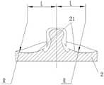
本实施例的股骨髁假体1的关节面的半径与中心距如表1-1,该表具有不同系列假体的半径与中心距。图7为本实施例的股骨髁假体1的左视图,该视图中的R表示股骨髁假体1的关节面的半径,L表示骨髁假体的关节面的中心距。本实施例提供的股骨髁假体1包括适用于不同人群的一系列假体,该系列假体的股骨髁关节面19的半径不同、中心距不同。具体地,本实施例提供的系列假体可以分为7个系列,每个系列的假体的半径与中心距均与其它系列的半径与中心距不同。进一步地,一系列的假体的股骨髁关节面19的半径根据一系列假体的系列号逐渐渐变,中心距与半径相适配,该系列的股骨髁假体1的半径与中心距可有效的降低股骨髁假体1与胫骨垫假体2之间的磨损。当假体植入,可按照个体的差异选择不同系列的股骨髁假体1。即时股骨髁假体1的型号与胫骨垫假体2的型号不匹配,由于本申请的股骨髁假体1的相邻系列的半径与中心距相近,最大程度上使得相邻型号间股骨髁关节面19的形状近似,可有效的降低股骨髁假体1的型号与胫骨垫假体2的型号不匹配时股骨髁假体1与胫骨垫假体2之间的磨损,降低假体松动的概率。The radii and center distances of the articular surface of the
表1-1Table 1-1
如图9所示,图10为本实施例的股骨髁假体1的结构示意图。本实施例提供的股骨髁假体1包括一体式连接的前髁11、股骨髁远端12和两个后髁13。进一步地,股骨髁远端12与两个后髁13之间形成小面积的髁间盒,髁间盒与股骨髁远端12和后髁13之间形成向外突出的髁间盒。股骨髁远端12与两个后髁13之间形成小面积的髁间盒15,小面积的髁间盒15可以保留更多的患者的骨量,具体地,髁间盒15呈近似长方形,股骨髁上与股骨髁远端12的连接处具有一个较小髁间盒前边缘111,髁间盒15的一端位于该髁间盒前边缘111上,本实施例的髁间盒15的形成是在股骨髁和股骨髁远端12直接挖槽形成,髁间盒15的形状小,且髁间盒15的深度小,形成较小面积的髁间盒15。髁间盒15与股骨髁远端12和后髁13之间形成向外突出的髁间盒15,髁间盒15可在胫骨垫假体2与髁间结构接触时能够提供一定的摩擦界面,不会使得胫骨垫假体2髁间立柱31与骨面直接接触,避免过度摩擦,避免过度摩擦引起的脱位。具体地,髁间盒边沿围绕髁间盒15设置,其为沿着髁间盒15边缘向上的突起,髁间盒15的深度较浅,股骨髁假体1采用金属股骨髁假体1,股骨髁假体1具有较小面积的髁间盒15,可以保留更多的患者的骨量。髁间盒15的周围具有髁间盒边沿,当髁间盒内安装其他零件时,避免过度摩擦,避免过度摩擦引起的脱位。As shown in FIG. 9 , FIG. 10 is a schematic structural diagram of the
如图9所示的,本实施例提供的股骨髁假体1上具有向外延伸的形成假体边界的假体边沿。本实施例提供的假体上具有向外延伸的形成假体边界的假体边沿18。位于前髁11上的假体边沿18的宽度由前髁11的顶部向股骨髁远端12延伸方向的逐渐增大。位于股骨髁远端12的假体边沿18的宽度趋于均匀;一个后髁13的假体边沿18的宽度大于另一个后髁13的假体边沿18的宽度,且宽度大的后髁13的假体边沿18与股骨髁远端12的假体边沿18之间圆弧过渡连接。假体边界处的假体边沿18根据假体的不同部分形成不同的假体边沿18,可更好的贴合截骨面,减少因假体外露产生的术后不适感或功能障碍。As shown in FIG. 9 , the
如图9所示的,本实施例提供的前髁11内侧的上半部分上设有倒U型浅槽,前髁11内侧的下半部分上对称设置两个L型浅槽。本实施例提供的前髁11内侧的上半部分上设有倒U型浅槽112,前髁11内侧的下半部分上对称设置两个L型浅槽113,倒U型浅槽112、L型浅槽113和前髁11的假体边沿18形成凹陷区间,该凹陷区间可较好的固定骨。本实施例提供的股骨髁远端12上设置有股骨髁固定柱;股骨髁远端12的上环绕股骨髁固定柱处设有两个开口相向设置的U型槽。股骨髁远端12的上环绕股骨髁固定柱均设有两个开口相向设置的U型槽,U型槽与股骨髁固定柱的假体边沿18形成凹陷区间,该凹陷区间可有效的固定骨。As shown in FIG. 9 , an inverted U-shaped shallow groove is provided on the upper half of the inner side of the
如图10所示的,图9为本实施例的胫骨垫假体2假体的结构示意图。本实施例的胫骨垫假体2假体的胫骨垫假体关节面21的半径与中心距的数据如表1-2所示,本实施例提供一种胫骨垫假体2假体,胫骨垫假体2假体上设置有胫骨垫假体关节面21,胫骨垫假体2假体包括适用于不同人群的一系列假体,该系列假体的胫骨垫假体关节面21的半径不同、中心距不同。当假体植入,可按照个体的差异选择不同系列的胫骨垫假体2假体。即时胫骨垫假体2假体的型号与股骨髁假体1的型号不匹配,由于本申请的股胫骨垫假体2假体的相邻系列的半径与中心距相近,最大程度上使得相邻型号间胫骨垫假体关节面21的形状近似,可有效的降低股胫骨垫假体2假体的型号与股骨髁假体1的型号不匹配时股骨髁假体1与胫骨垫假体2之间的磨损,降低假体松动的概率。As shown in FIG. 10 , FIG. 9 is a schematic structural diagram of the
表1-2Table 1-2
上述方案中,(1)本实施例提供的股骨髁假体1在屈曲时,髌骨沟槽后髁17与髌骨3的接触面积大,减小压强,减小聚乙烯的磨损,增大沟槽与髌骨3的稳定性;该沟槽可以满足不同的个体间差异,屈曲过程中逐渐变深的沟槽又可以为髌骨3提供足够的稳定束缚环境,这样既考虑了不同患者间的差异又考虑了髌骨3运动过程中的稳定性,两者兼顾;本实施例的股骨髁假体1的相邻系列的半径与中心距相近,最大程度上使得相邻型号间股骨髁关节面19的形状近似,可有效的降低股骨髁假体1的型号与胫骨垫假体2的型号不匹配时股骨髁假体1与胫骨垫假体2之间的磨损,降低假体松动的概率;本实施例提供的股骨髁假体1的小面积的髁间盒可以保留更多的患者的骨量;本实施例提供的股骨髁假体1的髁间盒的周围具有髁间盒边沿,当髁间盒内安装其他零件时,避免过度摩擦,避免过度摩擦引起的脱位;本实施例提供的股骨髁假体1的假体边界处的假体边沿根据假体的不同部分形成不同的假体边沿,可更好的贴合截骨面,减少因假体外露产生的术后不适感或功能障碍。In the above solution, (1) when the
(2)本实施例提供的胫骨垫假体2假体骨降低髁假体与胫骨垫假体2之间的磨损,降低假体松动的概率。(2) The
(3)本实施例提供的全膝关节假体可满足个体性的差异股骨髁假体1的髌骨沟槽17满足人体屈曲功能,且与髌骨3稳定连接;股骨髁假体1与胫骨垫假体2假体匹配性高,避免股骨髁关节面19与胫骨垫假体关节面21不匹配,降低股骨髁假体1与胫骨垫假体2假体的摩擦,降低假体松动。本实施例的股骨髁假体1的相邻系列的半径与中心距相近,最大程度上使得相邻型号间股骨髁关节面19的形状近似,可有效的降低股骨髁假体1的型号与胫骨垫假体2的型号不匹配时股骨髁假体1与胫骨垫假体2之间的磨损,降低假体松动的概率。(3) The total knee joint prosthesis provided in this embodiment can satisfy individual differences. The
本说明书中的各个实施例均采用递进的方式描述,每个实施例重点说明的都是与其他实施例的不同之处,各个实施例之间相同相似的部分互相参见即可。The various embodiments in this specification are described in a progressive manner, and each embodiment focuses on the differences from other embodiments, and the same and similar parts between the various embodiments may be referred to each other.
在本发明的描述中,需要理解的是,术语“上”、“一端”等指示的方位或位置关系为基于附图所示的方位或位置关系,仅是为了便于描述本发明和简化描述,而不是指示或暗示所指的装置或元件必须具有特定的方位、以特定的方位构造和操作,因此不能理解为对本发明的限制。In the description of the present invention, it should be understood that the orientation or positional relationship indicated by the terms "upper", "one end", etc. is based on the orientation or positional relationship shown in the accompanying drawings, and is only for the convenience of describing the present invention and simplifying the description, It is not intended to indicate or imply that the device or element referred to must have a particular orientation, be constructed and operate in a particular orientation, and therefore should not be construed as limiting the invention.
在本发明的描述中,需要说明的是,除非另有明确的规定和限定,术语“设有”、“连接”应做广义理解。例如,可以是固定连接,也可以是可拆卸连接,或一体地连接;可以是直接相连,也可以通过中间媒介间接相连。固定连接可以为焊接、螺纹连接和加紧等常见技术方案。对于本领域的普通技术人员而言,可以具体情况理解上述术语在本发明中的具体含义。In the description of the present invention, it should be noted that, unless otherwise expressly specified and limited, the terms "provided" and "connected" should be interpreted in a broad sense. For example, it may be a fixed connection, a detachable connection, or an integral connection; it may be a direct connection or an indirect connection through an intermediate medium. The fixed connection can be common technical solutions such as welding, screw connection and tightening. For those of ordinary skill in the art, the specific meanings of the above terms in the present invention can be understood in specific situations.
以上所述是本发明的优选实施方式,应当指出,对于本技术领域的普通技术人员来说,在不脱离本发明所述原理的前提下,还可以做出若干改进和润饰,这些改进和润饰也应视为本发明的保护范围。The above are the preferred embodiments of the present invention. It should be pointed out that for those skilled in the art, without departing from the principles of the present invention, several improvements and modifications can be made. These improvements and modifications It should also be regarded as the protection scope of the present invention.
Claims (10)
Translated fromChinesePriority Applications (2)
| Application Number | Priority Date | Filing Date | Title |
|---|---|---|---|
| CN202011541195.2ACN112603604B (en) | 2019-12-31 | 2020-04-09 | Total knee joint prosthesis |
| EP20217733.3AEP3845205A1 (en) | 2019-12-31 | 2020-12-30 | Full knee joint prosthesis |
Applications Claiming Priority (2)
| Application Number | Priority Date | Filing Date | Title |
|---|---|---|---|
| CN2019114200538 | 2019-12-31 | ||
| CN201911420053 | 2019-12-31 |
Related Child Applications (1)
| Application Number | Title | Priority Date | Filing Date |
|---|---|---|---|
| CN202011541195.2ADivisionCN112603604B (en) | 2019-12-31 | 2020-04-09 | Total knee joint prosthesis |
Publications (1)
| Publication Number | Publication Date |
|---|---|
| CN111529138Atrue CN111529138A (en) | 2020-08-14 |
Family
ID=71952220
Family Applications (2)
| Application Number | Title | Priority Date | Filing Date |
|---|---|---|---|
| CN202010274036.4AWithdrawnCN111529138A (en) | 2019-12-31 | 2020-04-09 | Total knee joint prosthesis |
| CN202011541195.2AActiveCN112603604B (en) | 2019-12-31 | 2020-04-09 | Total knee joint prosthesis |
Family Applications After (1)
| Application Number | Title | Priority Date | Filing Date |
|---|---|---|---|
| CN202011541195.2AActiveCN112603604B (en) | 2019-12-31 | 2020-04-09 | Total knee joint prosthesis |
Country Status (2)
| Country | Link |
|---|---|
| EP (1) | EP3845205A1 (en) |
| CN (2) | CN111529138A (en) |
Cited By (1)
| Publication number | Priority date | Publication date | Assignee | Title |
|---|---|---|---|---|
| CN112245073A (en)* | 2020-10-26 | 2021-01-22 | 北京力达康科技有限公司 | Femoral condyle prosthesis and knee joint prosthesis |
Families Citing this family (1)
| Publication number | Priority date | Publication date | Assignee | Title |
|---|---|---|---|---|
| WO2025074390A1 (en)* | 2023-10-03 | 2025-04-10 | Meril Healthcare Pvt. Ltd | Knee implant |
Family Cites Families (15)
| Publication number | Priority date | Publication date | Assignee | Title |
|---|---|---|---|---|
| US5330532A (en)* | 1990-11-09 | 1994-07-19 | Chitranjan Ranawat | Knee joint prosthesis |
| US6749638B1 (en)* | 2002-11-22 | 2004-06-15 | Zimmer Technology, Inc. | Modular knee prosthesis |
| CN102006839B (en)* | 2008-02-18 | 2014-07-23 | 麦克斯外科整形公司 | Total knee replacement prosthesis |
| CN201500213U (en)* | 2009-09-30 | 2010-06-09 | 北京纳通投资有限公司 | Knee joint prosthesis |
| US20140142714A1 (en)* | 2012-11-21 | 2014-05-22 | Abraham P. Wright | Knee prosthesis assembly having proportional coronal geometry |
| WO2014124233A1 (en)* | 2013-02-08 | 2014-08-14 | Orthopaedic International, Inc. | Instruments and methods for locating a femoral mechanical axis |
| US20140358241A1 (en)* | 2013-06-04 | 2014-12-04 | Jacques Afriat | Total knee prosthesis, and set of modular elements making it possible to obtain such a prosthesis |
| DE102014106999B4 (en)* | 2014-05-13 | 2018-03-29 | Implantec Deutschland Gmbh | Femoral implant and tibial implant, in particular as part of a knee prosthesis, and knee prosthesis comprising a corresponding femoral implant and / or tibial implant |
| WO2016026007A1 (en)* | 2014-08-21 | 2016-02-25 | Hoe Frederick | Knee prosthesis apparatus and methods and instrumentation for implantation thereof |
| CN204814288U (en)* | 2015-08-03 | 2015-12-02 | 北京威高亚华人工关节开发有限公司 | Full knee joint replacement false body |
| CN105748176A (en)* | 2016-04-26 | 2016-07-13 | 华中科技大学同济医学院附属同济医院 | Artificial total knee joint prosthesis of integral type |
| CN107753156A (en)* | 2017-10-16 | 2018-03-06 | 刘方 | Patient-specific knee-joint prosthesis |
| AU2019203591B2 (en)* | 2018-05-25 | 2024-11-14 | Howmedica Osteonics Corp. | Variable thickness femoral augments |
| CN109009575B (en)* | 2018-07-12 | 2024-02-20 | 宽岳医疗器材(苏州)有限公司 | Artificial knee joint prosthesis |
| CN109498220A (en)* | 2019-01-10 | 2019-03-22 | 上海交通大学医学院附属仁济医院 | A kind of artificial knee joint prosthesis of novel kneecap adaptation |
- 2020
- 2020-04-09CNCN202010274036.4Apatent/CN111529138A/ennot_activeWithdrawn
- 2020-04-09CNCN202011541195.2Apatent/CN112603604B/enactiveActive
- 2020-12-30EPEP20217733.3Apatent/EP3845205A1/ennot_activeWithdrawn
Cited By (2)
| Publication number | Priority date | Publication date | Assignee | Title |
|---|---|---|---|---|
| CN112245073A (en)* | 2020-10-26 | 2021-01-22 | 北京力达康科技有限公司 | Femoral condyle prosthesis and knee joint prosthesis |
| CN112245073B (en)* | 2020-10-26 | 2021-10-29 | 北京力达康科技有限公司 | Femoral condyle prosthesis and knee joint prosthesis |
Also Published As
| Publication number | Publication date |
|---|---|
| EP3845205A1 (en) | 2021-07-07 |
| CN112603604B (en) | 2021-11-19 |
| CN112603604A (en) | 2021-04-06 |
Similar Documents
| Publication | Publication Date | Title |
|---|---|---|
| US9649195B2 (en) | Femoral implant for preserving cruciate ligaments | |
| US10433966B2 (en) | Distal femoral knee prostheses | |
| CN101795643B (en) | Systems and methods for providing deeper knee flexion capabilities for knee prosthesis patients | |
| JP5208116B2 (en) | Posterior stable knee prosthesis | |
| US9839521B2 (en) | Prosthetic knee implant | |
| US10098747B2 (en) | Extended patellofemoral | |
| CN111467090B (en) | Unicondylar femoral prosthesis system and unicondylar femoral prosthesis | |
| CN107280818B (en) | Femoral-side prosthesis and tibial-side prosthesis for artificial knee replacement | |
| CN111529138A (en) | Total knee joint prosthesis | |
| JP2017505214A (en) | Artificial knee joint | |
| CN207755429U (en) | Knee-joint prosthesis | |
| JP2015530135A (en) | Replacement of the total knee prosthesis of the anterior cruciate ligament | |
| CN113616392A (en) | Total knee joint prosthesis | |
| CN111529137A (en) | Knee joint prosthesis and knee joint prosthesis assembly | |
| CN113180891A (en) | Tibia liner | |
| US8740985B1 (en) | Knee prosthesis | |
| CN213941066U (en) | Total knee joint prosthesis | |
| CN113616391A (en) | Femoral prosthesis | |
| CN103070739B (en) | Artificial knee-joint thighbone | |
| CN109124832B (en) | Femoral condyle prosthesis suitable for female patient | |
| CN213156734U (en) | Unicondylar femoral prosthesis system and unicondylar femoral prosthesis | |
| CN212438952U (en) | Tibial tray prosthesis | |
| CN113710208A (en) | Orthopaedic system with medial pivoting femoral component and insert | |
| CN216090943U (en) | Femoral prosthesis | |
| CN219397762U (en) | Interchangeable unicondylar prosthesis system |
Legal Events
| Date | Code | Title | Description |
|---|---|---|---|
| PB01 | Publication | ||
| PB01 | Publication | ||
| SE01 | Entry into force of request for substantive examination | ||
| SE01 | Entry into force of request for substantive examination | ||
| WW01 | Invention patent application withdrawn after publication | Application publication date:20200814 | |
| WW01 | Invention patent application withdrawn after publication |