CN111528980B - A femur positioning device for unicondylar replacement of knee joint fixation platform - Google Patents
A femur positioning device for unicondylar replacement of knee joint fixation platformDownload PDFInfo
- Publication number
- CN111528980B CN111528980BCN202010298807.3ACN202010298807ACN111528980BCN 111528980 BCN111528980 BCN 111528980BCN 202010298807 ACN202010298807 ACN 202010298807ACN 111528980 BCN111528980 BCN 111528980B
- Authority
- CN
- China
- Prior art keywords
- prosthesis
- positioning
- femoral
- femur
- drilling
- Prior art date
- Legal status (The legal status is an assumption and is not a legal conclusion. Google has not performed a legal analysis and makes no representation as to the accuracy of the status listed.)
- Active
Links
- 210000000689upper legAnatomy0.000titleclaimsabstractdescription19
- 210000000629knee jointAnatomy0.000titleclaimsabstractdescription13
- 238000005553drillingMethods0.000claimsabstractdescription46
- 125000006850spacer groupChemical group0.000claimsdescription9
- 230000001788irregularEffects0.000claimsdescription2
- 210000004417patellaAnatomy0.000abstractdescription6
- 210000002303tibiaAnatomy0.000abstractdescription4
- 230000000694effectsEffects0.000abstractdescription3
- 238000011882arthroplastyMethods0.000description10
- 210000003127kneeAnatomy0.000description7
- 238000010586diagramMethods0.000description5
- 238000001356surgical procedureMethods0.000description3
- 208000003947Knee OsteoarthritisDiseases0.000description1
- 241001227561ValgusSpecies0.000description1
- 241000469816VarusSpecies0.000description1
- 210000003423ankleAnatomy0.000description1
- 230000009286beneficial effectEffects0.000description1
- 210000000988bone and boneAnatomy0.000description1
- 210000004439collateral ligamentAnatomy0.000description1
- 230000007812deficiencyEffects0.000description1
- 238000005516engineering processMethods0.000description1
- 230000006870functionEffects0.000description1
- 238000009434installationMethods0.000description1
- 230000002452interceptive effectEffects0.000description1
- 210000002414legAnatomy0.000description1
- 230000007774longtermEffects0.000description1
- 238000005259measurementMethods0.000description1
- 238000000034methodMethods0.000description1
- 201000008482osteoarthritisDiseases0.000description1
- 230000009023proprioceptive sensationEffects0.000description1
- 238000011084recoveryMethods0.000description1
- 230000004083survival effectEffects0.000description1
- 238000011883total knee arthroplastyMethods0.000description1
Images


Classifications
- A—HUMAN NECESSITIES
- A61—MEDICAL OR VETERINARY SCIENCE; HYGIENE
- A61B—DIAGNOSIS; SURGERY; IDENTIFICATION
- A61B17/00—Surgical instruments, devices or methods
- A61B17/16—Instruments for performing osteoclasis; Drills or chisels for bones; Trepans
- A61B17/17—Guides or aligning means for drills, mills, pins or wires
- A61B17/1732—Guides or aligning means for drills, mills, pins or wires for bone breaking devices
- A—HUMAN NECESSITIES
- A61—MEDICAL OR VETERINARY SCIENCE; HYGIENE
- A61B—DIAGNOSIS; SURGERY; IDENTIFICATION
- A61B17/00—Surgical instruments, devices or methods
- A61B17/16—Instruments for performing osteoclasis; Drills or chisels for bones; Trepans
- A61B17/17—Guides or aligning means for drills, mills, pins or wires
- A61B17/1739—Guides or aligning means for drills, mills, pins or wires specially adapted for particular parts of the body
- A61B17/1764—Guides or aligning means for drills, mills, pins or wires specially adapted for particular parts of the body for the knee
- A—HUMAN NECESSITIES
- A61—MEDICAL OR VETERINARY SCIENCE; HYGIENE
- A61F—FILTERS IMPLANTABLE INTO BLOOD VESSELS; PROSTHESES; DEVICES PROVIDING PATENCY TO, OR PREVENTING COLLAPSING OF, TUBULAR STRUCTURES OF THE BODY, e.g. STENTS; ORTHOPAEDIC, NURSING OR CONTRACEPTIVE DEVICES; FOMENTATION; TREATMENT OR PROTECTION OF EYES OR EARS; BANDAGES, DRESSINGS OR ABSORBENT PADS; FIRST-AID KITS
- A61F2/00—Filters implantable into blood vessels; Prostheses, i.e. artificial substitutes or replacements for parts of the body; Appliances for connecting them with the body; Devices providing patency to, or preventing collapsing of, tubular structures of the body, e.g. stents
- A61F2/02—Prostheses implantable into the body
- A61F2/30—Joints
- A61F2/46—Special tools for implanting artificial joints
- A61F2/4601—Special tools for implanting artificial joints for introducing bone substitute, for implanting bone graft implants or for compacting them in the bone cavity
- A—HUMAN NECESSITIES
- A61—MEDICAL OR VETERINARY SCIENCE; HYGIENE
- A61F—FILTERS IMPLANTABLE INTO BLOOD VESSELS; PROSTHESES; DEVICES PROVIDING PATENCY TO, OR PREVENTING COLLAPSING OF, TUBULAR STRUCTURES OF THE BODY, e.g. STENTS; ORTHOPAEDIC, NURSING OR CONTRACEPTIVE DEVICES; FOMENTATION; TREATMENT OR PROTECTION OF EYES OR EARS; BANDAGES, DRESSINGS OR ABSORBENT PADS; FIRST-AID KITS
- A61F2/00—Filters implantable into blood vessels; Prostheses, i.e. artificial substitutes or replacements for parts of the body; Appliances for connecting them with the body; Devices providing patency to, or preventing collapsing of, tubular structures of the body, e.g. stents
- A61F2/02—Prostheses implantable into the body
- A61F2/30—Joints
- A61F2/46—Special tools for implanting artificial joints
- A61F2/4603—Special tools for implanting artificial joints for insertion or extraction of endoprosthetic joints or of accessories thereof
- A61F2/461—Special tools for implanting artificial joints for insertion or extraction of endoprosthetic joints or of accessories thereof of knees
- A—HUMAN NECESSITIES
- A61—MEDICAL OR VETERINARY SCIENCE; HYGIENE
- A61B—DIAGNOSIS; SURGERY; IDENTIFICATION
- A61B17/00—Surgical instruments, devices or methods
- A61B17/56—Surgical instruments or methods for treatment of bones or joints; Devices specially adapted therefor
- A61B2017/564—Methods for bone or joint treatment
- A—HUMAN NECESSITIES
- A61—MEDICAL OR VETERINARY SCIENCE; HYGIENE
- A61F—FILTERS IMPLANTABLE INTO BLOOD VESSELS; PROSTHESES; DEVICES PROVIDING PATENCY TO, OR PREVENTING COLLAPSING OF, TUBULAR STRUCTURES OF THE BODY, e.g. STENTS; ORTHOPAEDIC, NURSING OR CONTRACEPTIVE DEVICES; FOMENTATION; TREATMENT OR PROTECTION OF EYES OR EARS; BANDAGES, DRESSINGS OR ABSORBENT PADS; FIRST-AID KITS
- A61F2/00—Filters implantable into blood vessels; Prostheses, i.e. artificial substitutes or replacements for parts of the body; Appliances for connecting them with the body; Devices providing patency to, or preventing collapsing of, tubular structures of the body, e.g. stents
- A61F2/02—Prostheses implantable into the body
- A61F2/30—Joints
- A61F2/46—Special tools for implanting artificial joints
- A61F2002/4635—Special tools for implanting artificial joints using minimally invasive surgery
Landscapes
- Health & Medical Sciences (AREA)
- Orthopedic Medicine & Surgery (AREA)
- Life Sciences & Earth Sciences (AREA)
- Veterinary Medicine (AREA)
- Animal Behavior & Ethology (AREA)
- Surgery (AREA)
- Oral & Maxillofacial Surgery (AREA)
- Engineering & Computer Science (AREA)
- Biomedical Technology (AREA)
- Heart & Thoracic Surgery (AREA)
- Transplantation (AREA)
- Public Health (AREA)
- General Health & Medical Sciences (AREA)
- Nuclear Medicine, Radiotherapy & Molecular Imaging (AREA)
- Molecular Biology (AREA)
- Dentistry (AREA)
- Physical Education & Sports Medicine (AREA)
- Medical Informatics (AREA)
- Cardiology (AREA)
- Vascular Medicine (AREA)
- Prostheses (AREA)
- Surgical Instruments (AREA)
Abstract
Description
Translated fromChinese技术领域technical field
本申请涉及医疗器械技术领域,特别涉及膝关节微创单髁关节置换手术操作和精准股骨假体定位手术技术领域,具体是一种膝关节固定平台单髁置换术的股骨定位装置。This application relates to the technical field of medical devices, in particular to the technical field of minimally invasive unicondylar arthroplasty of the knee joint and the technical field of precise femoral prosthesis positioning surgery, and specifically a femoral positioning device for unicondylar knee arthroplasty on a fixed platform.
背景技术Background technique
膝关节单髁置换术已广泛用于治疗膝关节单间室骨性关节炎,其相对于全膝置换能更多的保留骨量,更接近生理的膝关节运动功能,更好的本体感觉和膝关节活动度以及患者更快的恢复。和活动平台单髁置换相比,固定平台单髁关节置换可用于膝关节内、外侧间室骨关节炎的治疗,而不用担心垫片滑脱等并发症的发生。但膝外侧单髁关节置换的手术技术难度较大,对于术者经验的要求较高,同时影响股骨侧假体定位的不确定因素较多,尚缺乏统一的参考标准,目前固定平台单髁置换的股骨侧截骨及定位主要依靠手动操作,实现高精准度的股骨假体力线及位置具有一定的难度,术者的经验非常重要,尤其对于初学者而言,更是巨大的挑战。若存在显著的股骨假体位置不佳,将影响单髁假体的长期生存率。Unicompartmental knee arthroplasty has been widely used in the treatment of unicompartmental osteoarthritis of the knee joint. Compared with total knee arthroplasty, it can preserve more bone mass, have a more physiological knee motion function, and better proprioception and knee arthroplasty. joint mobility and faster recovery for patients. Compared with unicondylar arthroplasty with movable platform, unicondylar arthroplasty with fixed platform can be used for the treatment of osteoarthritis in the inner and outer compartments of the knee joint without worrying about the occurrence of complications such as spacer slippage. However, the surgical technique of lateral unicompartmental knee arthroplasty is difficult and requires high experience of the surgeon. At the same time, there are many uncertain factors affecting the positioning of the femoral prosthesis, and there is still a lack of unified reference standards. Currently, unicondylar arthroplasty with a fixed platform The osteotomy and positioning of the femoral side mainly rely on manual operation, and it is difficult to achieve high-precision alignment and position of the femoral prosthesis. The experience of the surgeon is very important, especially for beginners, it is a huge challenge. The presence of significant femoral component malposition will affect the long-term survival of unicompartmental components.
申请内容application content
本申请的目的在于,克服现有的技术的不足,提供一种膝关节固定平台单髁置换术的股骨定位装置,主要用于微创小切口下完成膝关节固定平台单髁置换术并实现股骨假体的精准定位。The purpose of this application is to overcome the deficiencies of the existing technology and provide a femur positioning device for unicondylar replacement of the knee joint fixation platform, which is mainly used to complete the unicondylar replacement of the knee joint fixation platform and realize femoral Precise positioning of the prosthesis.
为实现上述目标,本申请提供了如下技术方案:In order to achieve the above goals, the application provides the following technical solutions:
一种膝关节固定平台单髁置换术的股骨定位装置,其特征在于,包括股骨钻孔导向器1、定位校准器2、单髁假体3;A femur positioning device for unicondylar replacement of a knee joint fixation platform, characterized in that it includes a
所述股骨钻孔导向器1包括上钻孔导向孔11、下钻孔导向孔(12)、定位钉定位孔13;股骨钻孔导向器1采用不规则形设计为上窄下宽结构,股骨钻孔导向器1的底座为弧形结构,术前股骨钻孔导向器1底座弧形面与股骨面贴合;上钻孔导向孔11、下钻孔导向孔12为空心圆柱体结构,两者与股骨钻孔导向器1弧形面固定连接,用于术中股骨钻孔导向;Described
所述定位校准器2包括:门型限位框21、左右两侧垫块22、凹形底座23、手柄24:门型限位框21位于左侧垫块22上部,门型限位框(21)下端与左侧垫块22固定连接,门型限位框21的框体内部尺寸和间距与上钻孔导向孔11、下钻孔导向孔12外径尺寸和间距相同;Described
垫块22厚度高于凹形底座23,呈为长方体条状结构,位于凹形底座23上方,与凹形底座23固定连接;The
凹形底座23为板状结构,两端为弧形;The
左侧垫块22与手柄24连接,手柄24呈外展状态;The
所述单髁假体3包括:上假体31、胫骨平台假体32;为现有技术,是使用过程中被试用的对象。The
一种膝关节固定平台单髁置换术的股骨定位装置,其特征在于:A femur positioning device for knee joint fixation platform unicondylar replacement, characterized in that:
根据胫骨平台假体32选用合适的定位校准器2,使凹形底座23高度h1与胫骨平台假体32高度h2相同,通过定位校准器2中凹形底座23弧面紧贴截骨后的胫骨平台假体32外侧(或内侧)壁,且门型限位框21的框体卡住股骨钻孔导向器1的两个导向孔(上钻孔导向孔11、下钻孔导向孔12)后完成股骨定位操作。Select a
有益效果:Beneficial effect:
本申请设计的一种膝关节固定平台单髁置换术的股骨定位装置,既可以方便在微创小切口下进行股骨假体大小的测量选择,无需过度牵拉髌骨,显著降低术中使用时髌骨的“遮挡”效应对股骨钻孔导向器放置的干扰。还可以进行股骨侧假体位置方向的精准定位,防止股骨假体发生内、外旋,内、外翻等不佳情况。仅需一人一步操作即可完成,不仅省时省力,步骤简化,而且可重复性强,精准度高。This application designs a femoral positioning device for unicompartmental knee arthroplasty, which can facilitate the measurement and selection of the size of the femoral prosthesis under a minimally invasive small incision, without excessive stretching of the patella, and significantly reduces the time of use of the patella during surgery. Interfering with the placement of the femoral drill guide by the "shadowing" effect of the It can also accurately locate the position and direction of the femoral prosthesis to prevent internal and external rotation, varus and valgus of the femoral prosthesis. It only needs one person to complete the operation in one step, which not only saves time and effort, simplifies the steps, but also has strong repeatability and high precision.
附图说明Description of drawings
图1为股骨钻孔导向器示意图;Fig. 1 is the schematic diagram of femoral drilling guide;
图2定位校准器示意图;Fig. 2 schematic diagram of positioning calibrator;
图3单踝假体示意图;Figure 3 Schematic diagram of single ankle prosthesis;
图4股骨钻孔导向器安装示意图;Figure 4 is a schematic diagram of installation of the femoral drill guide;
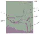
图5手术中定位校准器与股骨钻孔导向器位置关系图;Figure 5 is a positional relationship diagram between the positioning calibrator and the femoral drilling guide during the operation;
附图标记说明Explanation of reference signs
股骨钻孔导向器1、定位校准器2、单髁假体3;
股骨钻孔导向器1包括:上钻孔导向孔11、下钻孔导向孔12、定位钉定位孔13;定位校准器2包括:门型限位框21、垫块22、凹形底座23、手柄24;单髁假体3包括:上假体31、胫骨平台假体32;髌骨4、股骨踝5。The
具体实施方式:Detailed ways:
一种膝关节固定平台单髁置换术的股骨定位装置,包括股骨钻孔导向器1、定位校准器2、单髁假体3;所述股骨钻孔导向器1包括上钻孔导向孔11、下钻孔导向孔12、定位钉定位孔13;所述定位校准器2包括:门型限位框21、垫块22、凹形底座23、手柄24;单髁假体3包括:上假体31、胫骨平台假体32。A femur positioning device for knee joint fixation platform unicondylar replacement, comprising a
如图1所示,所述股骨钻孔导向器1采用不规则形设计为上窄下宽结构;如图4所示,髌骨位于股骨钻孔导向器1上部窄体旁,这种上窄下宽结构结构用于减少术中髌骨4对股骨钻孔导向器1的“遮挡”效应,防止髌骨4对股骨钻孔导向器1放置位置的干扰;股骨钻孔导向器1的底座为弧形结构,术前股骨钻孔导向器1底座弧形面与股骨面贴合;上钻孔导向孔11、下钻孔导向孔12为空心圆柱体结构,两者与股骨钻孔导向器1弧形面固定连接,用于术中股骨钻孔导向;定位钉定位孔13位于股骨钻孔导向器1弧形面上,为空心圆结构,用于术中定位钉定位。As shown in Fig. 1, described
如图2所示,门型限位框21位于垫块22上部,门型限位框21下端与垫块22固定连接,门型限位框21的框体尺寸和间距与上钻孔导向孔11、下钻孔导向孔12外径尺寸和间距相同;垫块22为长方体结构,位于凹形底座23上方,与凹形底座23固定连接,垫块22厚度恰好等于胫骨假体的厚度,不仅可以测试评估假体试模的伸屈间隙平衡情况,更重要的是可以在准备股骨侧钻孔时恢复侧副韧带正常的张力,股骨和胫骨也回到正常的相对位置;凹形底座23为板状结构,两端为弧形,底部固定与手柄24平台上,凹形底座23高度为h1,术中凹型底座23弧面紧贴截骨后的胫骨平台假体32外侧(或内侧)壁;手柄24为手持定位校准器2的把手,便于术中医生手持。As shown in Figure 2, the door-shaped limiting
单髁假体3为现有技术装置,包括:上假体31、胫骨平台假体32;所述胫骨平台假体32为半圆形板块结构,胫骨平台假体32高度为h2;The
如图5所示,一种膝关节固定平台单髁置换术的股骨定位装置使用原理:As shown in Figure 5, the principle of use of a femoral positioning device for unicompartmental knee arthroplasty:
通过定位校准器2中凹形底座23弧面紧贴截骨后的胫骨平台假体32外侧(或内侧)壁,且门型限位框21内部框体卡住股骨钻孔导向器1的两个导向孔(上钻孔导向孔11、下钻孔导向孔12)完成股骨定位操作。The arc surface of
实施例1:Example 1:
一种膝关节固定平台单髁置换术的股骨定位装置使用步骤为:A femur positioning device for knee joint fixation platform unicompartmental replacement uses steps as follows:
s1:以腿完全伸直标记的股骨假体上缘为参照,选取合适型号的股骨钻孔导向器1,并将股骨钻孔导向器1底座与股骨5端贴合,并安装胫骨平台假体32;s1: With the upper edge of the femoral prosthesis marked when the leg is fully extended as a reference, select the appropriate model of the
s2:选择与胫骨平台假体32匹配的定位校准器2,使胫骨平台假体32高度h2与凹形底座23高度h1相同;s2: Select the
s3:定位校准器2中凹形底座23弧面紧贴截骨后的胫骨平台假体32外侧(或内侧)壁;s3: The arc surface of the
s4:门型限位框21内矿体卡住股骨钻孔导向器1的两个导向孔(上钻孔导向孔11、下钻孔导向孔12);s4: The ore body in the door-shaped limiting
s5:完成股骨定位操作,进行股骨钻孔。s5: The femoral positioning operation is completed, and the femoral drilling is performed.
Claims (2)
Translated fromChinesePriority Applications (1)
| Application Number | Priority Date | Filing Date | Title |
|---|---|---|---|
| CN202010298807.3ACN111528980B (en) | 2020-04-16 | 2020-04-16 | A femur positioning device for unicondylar replacement of knee joint fixation platform |
Applications Claiming Priority (1)
| Application Number | Priority Date | Filing Date | Title |
|---|---|---|---|
| CN202010298807.3ACN111528980B (en) | 2020-04-16 | 2020-04-16 | A femur positioning device for unicondylar replacement of knee joint fixation platform |
Publications (2)
| Publication Number | Publication Date |
|---|---|
| CN111528980A CN111528980A (en) | 2020-08-14 |
| CN111528980Btrue CN111528980B (en) | 2023-06-20 |
Family
ID=71973212
Family Applications (1)
| Application Number | Title | Priority Date | Filing Date |
|---|---|---|---|
| CN202010298807.3AActiveCN111528980B (en) | 2020-04-16 | 2020-04-16 | A femur positioning device for unicondylar replacement of knee joint fixation platform |
Country Status (1)
| Country | Link |
|---|---|
| CN (1) | CN111528980B (en) |
Families Citing this family (3)
| Publication number | Priority date | Publication date | Assignee | Title |
|---|---|---|---|---|
| CN112155809B (en)* | 2020-09-28 | 2024-08-20 | 宁波市第二医院 | Tibia unicondylar prosthesis holder |
| CN113081408B (en)* | 2021-04-02 | 2024-07-02 | 上海市杨浦区中心医院(同济大学附属杨浦医院) | Single-condyle replacement femoral prosthesis implantation positioner |
| CN113397651B (en)* | 2021-07-21 | 2023-04-18 | 袁海浪 | Auxiliary positioning device for longitudinal tibial osteotomy position in unicondylar replacement |
Citations (8)
| Publication number | Priority date | Publication date | Assignee | Title |
|---|---|---|---|---|
| WO2011147832A1 (en)* | 2010-05-24 | 2011-12-01 | Episurf Medical Ab | System of manufacturing a surgical kit for cartilage repair in a joint |
| CN102793594A (en)* | 2012-08-18 | 2012-11-28 | 深圳清华大学研究院 | Artificial knee joint |
| CN102869323A (en)* | 2010-05-04 | 2013-01-09 | 德普伊国际有限公司 | Alignment guide |
| CN104398306A (en)* | 2014-12-15 | 2015-03-11 | 柏云云 | Ultrasound intervention puncture needle guidance monitoring system and method |
| WO2016110338A1 (en)* | 2015-01-06 | 2016-07-14 | Waldemar Link Gmbh & Co. Kg | Jig for determining a patient-adapted implant size of the femoral implant of a knee endoprosthesis |
| CN210077796U (en)* | 2019-03-19 | 2020-02-18 | 苏州国科美润达医疗技术有限公司 | Aiming and guiding device for bone nail fixing hole |
| CN210138182U (en)* | 2019-03-15 | 2020-03-13 | 黄月秋 | Three-jaw bone holder for orthopedic surgery |
| CN110960289A (en)* | 2019-12-03 | 2020-04-07 | 嘉思特华剑医疗器材(天津)有限公司 | Single-condyle bone cutting guide plate and positioning method thereof |
Family Cites Families (1)
| Publication number | Priority date | Publication date | Assignee | Title |
|---|---|---|---|---|
| US11298245B2 (en)* | 2018-01-16 | 2022-04-12 | Limacorporate S.P.A. | Method for surgical application of a glenoid prosthesis component of a shoulder joint prosthesis and relating surgical instruments |
- 2020
- 2020-04-16CNCN202010298807.3Apatent/CN111528980B/enactiveActive
Patent Citations (8)
| Publication number | Priority date | Publication date | Assignee | Title |
|---|---|---|---|---|
| CN102869323A (en)* | 2010-05-04 | 2013-01-09 | 德普伊国际有限公司 | Alignment guide |
| WO2011147832A1 (en)* | 2010-05-24 | 2011-12-01 | Episurf Medical Ab | System of manufacturing a surgical kit for cartilage repair in a joint |
| CN102793594A (en)* | 2012-08-18 | 2012-11-28 | 深圳清华大学研究院 | Artificial knee joint |
| CN104398306A (en)* | 2014-12-15 | 2015-03-11 | 柏云云 | Ultrasound intervention puncture needle guidance monitoring system and method |
| WO2016110338A1 (en)* | 2015-01-06 | 2016-07-14 | Waldemar Link Gmbh & Co. Kg | Jig for determining a patient-adapted implant size of the femoral implant of a knee endoprosthesis |
| CN210138182U (en)* | 2019-03-15 | 2020-03-13 | 黄月秋 | Three-jaw bone holder for orthopedic surgery |
| CN210077796U (en)* | 2019-03-19 | 2020-02-18 | 苏州国科美润达医疗技术有限公司 | Aiming and guiding device for bone nail fixing hole |
| CN110960289A (en)* | 2019-12-03 | 2020-04-07 | 嘉思特华剑医疗器材(天津)有限公司 | Single-condyle bone cutting guide plate and positioning method thereof |
Also Published As
| Publication number | Publication date |
|---|---|
| CN111528980A (en) | 2020-08-14 |
Similar Documents
| Publication | Publication Date | Title |
|---|---|---|
| CN111528980B (en) | A femur positioning device for unicondylar replacement of knee joint fixation platform | |
| US9622761B2 (en) | Knee balancing for revision procedures | |
| US8888718B2 (en) | Joint stability arrangement and method | |
| US20060241637A1 (en) | Method and apparatus for achieving correct limb alignment in unicondylar knee arthroplasty | |
| CN105193475A (en) | Individualized bone cutting guide plate suite and design method thereof | |
| CN106236289A (en) | Femoral rotation osteotomy automatic backlash static organ in a kind of total knee arthroplasty | |
| CN102499843A (en) | Knee arthroscope operation stent | |
| CN205234503U (en) | A shin bone section bone auxiliary device that is used for accurate demonstration to cut surface of bone hypsokinesis angle | |
| CN218105892U (en) | Knee joint postoperative mobility detection device | |
| CN206372138U (en) | Femoral rotation osteotomy automatic backlash balancer in a kind of total knee arthroplasty | |
| CN208426163U (en) | Knee prosthesis shin bone hypsokinesis osteotomy positioning auxiliary device | |
| WO2021056149A1 (en) | Anatomical endpoint positioning method for medial patellofemoral ligament | |
| CN214966280U (en) | Tibia rotation alignment positioning device in total knee joint replacement | |
| CN112641519B (en) | Auxiliary device for knee arthroscopic surgery | |
| CN205054339U (en) | Individuation knee joint shin bone near -end cuts bone conduction board | |
| CN209236720U (en) | An orthopedic surgery auxiliary frame | |
| CN108836426B (en) | Osteotomy sighting device and application method thereof | |
| Ghijselings et al. | Using a patella reduced technique while balancing a TKA results in restored physiological strain in the collateral ligaments: an ex vivo kinematic analysis | |
| CN221205618U (en) | Tibia positioner for treating knee joint posterior cruciate ligament avulsion fracture | |
| Harding et al. | The importance of femoral intramedullary entry point in knee arthroplasty | |
| CN217448355U (en) | Intraoperative C-shaped femur distal end fracture force line measuring device | |
| CN217660028U (en) | Auxiliary device in single condyle replacement based on kinematics alignment | |
| Ranawat et al. | Technique of Total knee arthroplasty with precision cut instruments | |
| CN221932451U (en) | A balancing device | |
| CN214318083U (en) | A 3D printed personalized femoral tunnel locator for anterior cruciate ligament reconstruction |
Legal Events
| Date | Code | Title | Description |
|---|---|---|---|
| PB01 | Publication | ||
| PB01 | Publication | ||
| SE01 | Entry into force of request for substantive examination | ||
| SE01 | Entry into force of request for substantive examination | ||
| GR01 | Patent grant | ||
| GR01 | Patent grant |