CN111528525A - A liquid storage element, a liquid conducting element, a cooling element, a condensate absorbing element and a supporting element - Google Patents
A liquid storage element, a liquid conducting element, a cooling element, a condensate absorbing element and a supporting elementDownload PDFInfo
- Publication number
- CN111528525A CN111528525ACN201911291779.6ACN201911291779ACN111528525ACN 111528525 ACN111528525 ACN 111528525ACN 201911291779 ACN201911291779 ACN 201911291779ACN 111528525 ACN111528525 ACN 111528525A
- Authority
- CN
- China
- Prior art keywords
- liquid
- element according
- liquid storage
- cooling
- skin layer
- Prior art date
- Legal status (The legal status is an assumption and is not a legal conclusion. Google has not performed a legal analysis and makes no representation as to the accuracy of the status listed.)
- Pending
Links
Images


Classifications
- A—HUMAN NECESSITIES
- A01—AGRICULTURE; FORESTRY; ANIMAL HUSBANDRY; HUNTING; TRAPPING; FISHING
- A01M—CATCHING, TRAPPING OR SCARING OF ANIMALS; APPARATUS FOR THE DESTRUCTION OF NOXIOUS ANIMALS OR NOXIOUS PLANTS
- A01M13/00—Fumigators; Apparatus for distributing gases
- A01M13/003—Enclosures for fumigation, e.g. containers, bags or housings
- A—HUMAN NECESSITIES
- A24—TOBACCO; CIGARS; CIGARETTES; SIMULATED SMOKING DEVICES; SMOKERS' REQUISITES
- A24F—SMOKERS' REQUISITES; MATCH BOXES; SIMULATED SMOKING DEVICES
- A24F40/00—Electrically operated smoking devices; Component parts thereof; Manufacture thereof; Maintenance or testing thereof; Charging means specially adapted therefor
- A24F40/10—Devices using liquid inhalable precursors
- A—HUMAN NECESSITIES
- A01—AGRICULTURE; FORESTRY; ANIMAL HUSBANDRY; HUNTING; TRAPPING; FISHING
- A01M—CATCHING, TRAPPING OR SCARING OF ANIMALS; APPARATUS FOR THE DESTRUCTION OF NOXIOUS ANIMALS OR NOXIOUS PLANTS
- A01M13/00—Fumigators; Apparatus for distributing gases
- A—HUMAN NECESSITIES
- A01—AGRICULTURE; FORESTRY; ANIMAL HUSBANDRY; HUNTING; TRAPPING; FISHING
- A01M—CATCHING, TRAPPING OR SCARING OF ANIMALS; APPARATUS FOR THE DESTRUCTION OF NOXIOUS ANIMALS OR NOXIOUS PLANTS
- A01M29/00—Scaring or repelling devices, e.g. bird-scaring apparatus
- A01M29/12—Scaring or repelling devices, e.g. bird-scaring apparatus using odoriferous substances, e.g. aromas, pheromones or chemical agents
- A—HUMAN NECESSITIES
- A24—TOBACCO; CIGARS; CIGARETTES; SIMULATED SMOKING DEVICES; SMOKERS' REQUISITES
- A24F—SMOKERS' REQUISITES; MATCH BOXES; SIMULATED SMOKING DEVICES
- A24F40/00—Electrically operated smoking devices; Component parts thereof; Manufacture thereof; Maintenance or testing thereof; Charging means specially adapted therefor
- A24F40/40—Constructional details, e.g. connection of cartridges and battery parts
- A24F40/44—Wicks
- A—HUMAN NECESSITIES
- A24—TOBACCO; CIGARS; CIGARETTES; SIMULATED SMOKING DEVICES; SMOKERS' REQUISITES
- A24F—SMOKERS' REQUISITES; MATCH BOXES; SIMULATED SMOKING DEVICES
- A24F40/00—Electrically operated smoking devices; Component parts thereof; Manufacture thereof; Maintenance or testing thereof; Charging means specially adapted therefor
- A24F40/40—Constructional details, e.g. connection of cartridges and battery parts
- A24F40/46—Shape or structure of electric heating means
- A—HUMAN NECESSITIES
- A24—TOBACCO; CIGARS; CIGARETTES; SIMULATED SMOKING DEVICES; SMOKERS' REQUISITES
- A24F—SMOKERS' REQUISITES; MATCH BOXES; SIMULATED SMOKING DEVICES
- A24F40/00—Electrically operated smoking devices; Component parts thereof; Manufacture thereof; Maintenance or testing thereof; Charging means specially adapted therefor
- A24F40/40—Constructional details, e.g. connection of cartridges and battery parts
- A24F40/48—Fluid transfer means, e.g. pumps
- A24F40/485—Valves; Apertures
- A—HUMAN NECESSITIES
- A24—TOBACCO; CIGARS; CIGARETTES; SIMULATED SMOKING DEVICES; SMOKERS' REQUISITES
- A24F—SMOKERS' REQUISITES; MATCH BOXES; SIMULATED SMOKING DEVICES
- A24F40/00—Electrically operated smoking devices; Component parts thereof; Manufacture thereof; Maintenance or testing thereof; Charging means specially adapted therefor
- A24F40/50—Control or monitoring
- A—HUMAN NECESSITIES
- A24—TOBACCO; CIGARS; CIGARETTES; SIMULATED SMOKING DEVICES; SMOKERS' REQUISITES
- A24F—SMOKERS' REQUISITES; MATCH BOXES; SIMULATED SMOKING DEVICES
- A24F47/00—Smokers' requisites not otherwise provided for
- A—HUMAN NECESSITIES
- A61—MEDICAL OR VETERINARY SCIENCE; HYGIENE
- A61L—METHODS OR APPARATUS FOR STERILISING MATERIALS OR OBJECTS IN GENERAL; DISINFECTION, STERILISATION OR DEODORISATION OF AIR; CHEMICAL ASPECTS OF BANDAGES, DRESSINGS, ABSORBENT PADS OR SURGICAL ARTICLES; MATERIALS FOR BANDAGES, DRESSINGS, ABSORBENT PADS OR SURGICAL ARTICLES
- A61L9/00—Disinfection, sterilisation or deodorisation of air
- A61L9/015—Disinfection, sterilisation or deodorisation of air using gaseous or vaporous substances, e.g. ozone
- A61L9/02—Disinfection, sterilisation or deodorisation of air using gaseous or vaporous substances, e.g. ozone using substances evaporated in the air by heating or combustion
- A61L9/03—Apparatus therefor
- A61L9/037—Apparatus therefor comprising a wick
- D—TEXTILES; PAPER
- D01—NATURAL OR MAN-MADE THREADS OR FIBRES; SPINNING
- D01D—MECHANICAL METHODS OR APPARATUS IN THE MANUFACTURE OF ARTIFICIAL FILAMENTS, THREADS, FIBRES, BRISTLES OR RIBBONS
- D01D5/00—Formation of filaments, threads, or the like
- D01D5/28—Formation of filaments, threads, or the like while mixing different spinning solutions or melts during the spinning operation; Spinnerette packs therefor
- D01D5/30—Conjugate filaments; Spinnerette packs therefor
- D01D5/34—Core-skin structure; Spinnerette packs therefor
- D—TEXTILES; PAPER
- D01—NATURAL OR MAN-MADE THREADS OR FIBRES; SPINNING
- D01F—CHEMICAL FEATURES IN THE MANUFACTURE OF ARTIFICIAL FILAMENTS, THREADS, FIBRES, BRISTLES OR RIBBONS; APPARATUS SPECIALLY ADAPTED FOR THE MANUFACTURE OF CARBON FILAMENTS
- D01F8/00—Conjugated, i.e. bi- or multicomponent, artificial filaments or the like; Manufacture thereof
- D01F8/04—Conjugated, i.e. bi- or multicomponent, artificial filaments or the like; Manufacture thereof from synthetic polymers
- D01F8/14—Conjugated, i.e. bi- or multicomponent, artificial filaments or the like; Manufacture thereof from synthetic polymers with at least one polyester as constituent
Landscapes
- Life Sciences & Earth Sciences (AREA)
- Engineering & Computer Science (AREA)
- Health & Medical Sciences (AREA)
- Pest Control & Pesticides (AREA)
- General Health & Medical Sciences (AREA)
- Zoology (AREA)
- Insects & Arthropods (AREA)
- Environmental Sciences (AREA)
- Wood Science & Technology (AREA)
- Toxicology (AREA)
- Textile Engineering (AREA)
- Chemical & Material Sciences (AREA)
- General Chemical & Material Sciences (AREA)
- Chemical Kinetics & Catalysis (AREA)
- Public Health (AREA)
- Birds (AREA)
- Veterinary Medicine (AREA)
- Animal Behavior & Ethology (AREA)
- Epidemiology (AREA)
- Mechanical Engineering (AREA)
- Catching Or Destruction (AREA)
- Nonwoven Fabrics (AREA)
- Thermotherapy And Cooling Therapy Devices (AREA)
- Medicinal Preparation (AREA)
- Containers And Packaging Bodies Having A Special Means To Remove Contents (AREA)
- Disinfection, Sterilisation Or Deodorisation Of Air (AREA)
Abstract
Description
Translated fromChinese技术领域technical field
本发明涉及一种储液元件、导液元件、冷却元件、冷凝液吸收元件及支撑元件,特别涉及将液体气化或雾化的气雾散发装置中储存和释放液体的储液元件、传导液体的导液元件、冷却气雾的冷却元件、吸收冷凝液的冷凝液吸收元件、及支撑风味变换部件的支撑元件。The present invention relates to a liquid storage element, a liquid conducting element, a cooling element, a condensate absorption element and a supporting element, and in particular to a liquid storage element, a liquid conducting element for storing and releasing liquid in an aerosol emitting device for vaporizing or atomizing liquid The liquid conducting element, the cooling element for cooling the aerosol, the condensate absorbing element for absorbing the condensate, and the supporting element for supporting the flavor changing member.
背景技术Background technique
使用传统烟草的时候,吸入燃烧烟草时产生焦油等有害物质会影响身体健康,电子烟中,通常采用加热气化或加热雾化有效成份的方法来代替燃烧传统烟草的方法。在常见的加热液体烟油雾化的方法中,液体被储存于油仓中,雾化的气雾从油仓导出,这种结构的电子烟液体容易泄漏。也有的电子烟中采用棉花或无纺布缠绕在玻纤或陶瓷的管子上,然后将烟液注在棉花或无纺布上,由于棉花和无纺布缺乏三维立体形状和强度,难以自动化组装,并且棉花或无纺布缠绕后不均匀,局部密度较高,储液容量较小,使用后期对烟油释放能力较差,使用后液体残留率较高。电蚊香、电香薰和药物雾化吸入的装置等将液体气化或雾化的气雾散发装置中也存在类似的问题。When using traditional tobacco, harmful substances such as tar produced when inhaling burning tobacco will affect the health of the body. In electronic cigarettes, the method of heating and vaporizing or heating and atomizing the active ingredients is usually used to replace the method of burning traditional tobacco. In the common method of heating liquid e-liquid for atomization, the liquid is stored in the oil tank, and the atomized aerosol is exported from the oil tank. The electronic cigarette liquid of this structure is easy to leak. In some electronic cigarettes, cotton or non-woven fabrics are wound on glass fiber or ceramic tubes, and then the e-liquid is injected on the cotton or non-woven fabrics. Due to the lack of three-dimensional shape and strength of cotton and non-woven fabrics, it is difficult to automate assembly. , and the cotton or non-woven fabrics are not uniform after winding, the local density is high, the liquid storage capacity is small, the ability to release e-liquid in the later period of use is poor, and the residual rate of liquid after use is high. Similar problems exist in aerosol dispersing devices that vaporize or atomize liquids, such as electric mosquito coils, electric aromatherapy, and drug inhalation devices.
又,在电子烟、电蚊香、电香薰和药物雾化吸入的装置等,常见的一种结构是在气雾散发装置中安装雾化芯,如预埋电热丝的多孔陶瓷。当气流通过雾化装置的同时雾化芯加热,液体被雾化并被气流带出。为了将储液部中的液体比较平稳地传导给雾化芯并防止液体泄漏,通常在雾化芯表面包覆无纺布,并固定于气雾散发装置中。由于无纺布柔软缺少强度、容易褶皱,难以制成质量稳定的气雾散发装置,褶皱严重的情况下容易发生液体泄漏。在雾化芯表面包覆无纺布的方法需要大量人工,难以自动化,成本高、效率低。In addition, in electronic cigarettes, electric mosquito coils, electric aromatherapy and drug inhalation devices, a common structure is to install an atomizing core in the aerosol emitting device, such as porous ceramics with pre-embedded heating wires. When the air flow passes through the atomizing device and the atomizing core is heated, the liquid is atomized and carried out by the air flow. In order to conduct the liquid in the liquid storage part to the atomizing core relatively smoothly and prevent the liquid from leaking, the surface of the atomizing core is usually covered with non-woven fabric and fixed in the aerosol dispensing device. Because the non-woven fabric is soft and lacks strength and is easy to wrinkle, it is difficult to make an aerosol emission device with stable quality, and liquid leakage is prone to occur in the case of serious wrinkles. The method of coating the non-woven fabric on the surface of the atomizing core requires a lot of labor, is difficult to automate, has high cost and low efficiency.
又,传统卷烟燃烧时的温度在800℃左右,如此高温使烟草中的水分在形成气雾时,其中的大部分水被蒸发掉,气雾相对干燥,使用者吸入气雾时感知的温度较低。在不燃烧的情况下通过加热气雾基体产生的气雾或气溶胶中,可能含有较高的水分以及从气雾基体气化的气雾剂,如丙二醇、甘油等,使用者吸入气雾时感知的温度较高。未经适当冷却的加热不燃烧气雾甚至会使使用者感到烫嘴。使用加热不燃烧中药时,吸食者会遇到同样的问题。In addition, the burning temperature of traditional cigarettes is around 800°C. Such a high temperature causes most of the water in the tobacco to evaporate when the aerosol is formed, and the aerosol is relatively dry. Low. The aerosol or aerosol produced by heating the aerosol substrate without burning may contain high moisture and aerosols vaporized from the aerosol substrate, such as propylene glycol, glycerin, etc., when the user inhales the aerosol The perceived temperature is higher. Heat-not-burn aerosols that are not properly cooled can even cause the user's mouth to burn. Smokers experience the same problem when using heat-not-burn Chinese medicine.
可以在气雾基体下游采用冷却元件来吸收气雾中的热量从而冷却气雾。气雾通过热交换把自身的热量传导给冷却元件而降低温度,冷却元件吸收气雾中的热量后温度升高,如果冷却元件中的物质在吸收热量后发生熔化等相变过程,则可以更多地吸收气雾中的热量,使气雾的降温效果更为显著。为使热交换充分进行,冷却元件需要有大的表面积与气雾接触。参考被广泛使用的翅片式热交换器,可以采用薄片状物质来制作冷却元件。CN104203015A公开了用片材制作冷却元件来冷却加热不燃烧气雾的方法。但从热交换接触面积的角度来说,薄片是二维结构,比表面积较小。此外,根据CN104203015A所公开的,用薄片制作的冷却元件不能邻接气雾基体,中间需用其他元件隔开。显然,用薄片制作的冷却元件也不能高效吸收气雾中的小液滴。综上,在气雾散发装置中薄片制作的冷却元件有诸多局限性。药物雾化吸入的装置等将液体加热气化或雾化的气雾散发装置中也存在类似的问题。Cooling elements may be employed downstream of the aerosol matrix to absorb heat from the aerosol to cool the aerosol. The aerosol conducts its own heat to the cooling element through heat exchange to reduce the temperature. After the cooling element absorbs the heat in the aerosol, the temperature rises. If the material in the cooling element undergoes a phase transition process such as melting after absorbing heat, it can be more The heat in the mist is absorbed more, so that the cooling effect of the mist is more significant. For adequate heat exchange, the cooling element needs to have a large surface area in contact with the aerosol. With reference to the widely used finned heat exchanger, the cooling element can be fabricated from a sheet-like substance. CN104203015A discloses a method for cooling heat not burn aerosols by making cooling elements from sheet material. But from the point of view of the heat exchange contact area, the flakes are two-dimensional structures with small specific surface area. In addition, according to the disclosure of CN104203015A, the cooling elements made of thin sheets cannot be adjacent to the aerosol substrate, and need to be separated by other elements. Apparently, cooling elements made of thin sheets also cannot efficiently absorb the small droplets in the aerosol. In conclusion, there are many limitations of sheet-made cooling elements in aerosol emission devices. Similar problems exist in aerosol dispersing devices that heat liquids to vaporize or atomize, such as devices for inhaling drugs.
又,使用传统烟草的时候,吸入燃烧烟草时产生焦油等物质对健康危害较大,电子雾化烟采用加热雾化溶剂来摄入尼古丁或尼古丁盐,这种方法不产生焦油。电子雾化烟中的常用溶剂为1,2丙二醇和甘油,沸点分别为188.2℃和290℃,由于气雾通道的周壁温度较低,雾化后的气雾通过气雾通道的过程中冷凝液不断增加。大量的冷凝液进入口中时会严重影响使用者的口感,因此在气雾入口前去除大部分冷凝液能大幅度提升电子雾化烟的吸烟体验。可使用适当的吸收物质(冷凝液吸收元件)与冷凝液接触来去除冷凝液。有的雾化装置中,冷凝液会沉降到雾化器底部,这种情况下可以在雾化器底部安装冷凝液吸收体来防止冷凝液渗入主机。较为常见冷凝液吸收元件由多层无纺布叠加在一起并模切成要求的大小和形状,由于无纺布柔软、并缺乏固定的立体形状,在狭小的电子雾化气雾雾通道中安装或固定困难。另一种较为常见的冷凝液吸收元件由纤维或木浆压缩成片状,根据需要切成要求的大小和形状,或根据需要冲孔形成气流通道,这种冷凝液吸收元件俗称高压棉。其优点是可以制成立体形状,便于安装,高压棉的缺点是吸收冷凝液后明显膨胀,使用过程中气雾通道的气阻不稳定,影响使用体验。药物雾化吸入的装置等将液体气化或雾化的散发装置中也存在类似的问题。In addition, when using traditional tobacco, substances such as tar generated when inhaling burning tobacco are more harmful to health. Electronic atomized cigarettes use heated atomized solvents to ingest nicotine or nicotine salts. This method does not produce tar. The commonly used solvents in electronic atomizing cigarettes are 1, 2 propylene glycol and glycerin, with boiling points of 188.2 °C and 290 °C respectively. Due to the low temperature of the surrounding wall of the aerosol channel, the atomized aerosol condenses during the process of passing through the aerosol channel. Increasing. When a large amount of condensate enters the mouth, it will seriously affect the user's taste. Therefore, removing most of the condensate before the entrance of the aerosol can greatly improve the smoking experience of the vape. The condensate can be removed by contacting the condensate with a suitable absorbing material (condensate absorbing element). In some atomization devices, the condensate will settle to the bottom of the atomizer. In this case, a condensate absorber can be installed at the bottom of the atomizer to prevent the condensate from penetrating into the host. The more common condensate absorbing elements are stacked together by multiple layers of non-woven fabrics and die-cut to the required size and shape. Due to the softness of the non-woven fabric and the lack of a fixed three-dimensional shape, it is installed in a narrow electronic atomization aerosol channel. or fixation difficulties. Another common condensate absorbing element is compressed into sheets by fiber or wood pulp, cut into required size and shape as needed, or punched to form airflow channels as needed, this condensate absorbing element is commonly known as high-pressure cotton. The advantage is that it can be made into a three-dimensional shape, which is easy to install. The disadvantage of high-pressure cotton is that it expands significantly after absorbing condensate, and the air resistance of the aerosol channel is unstable during use, which affects the use experience. Similar problems exist in dispensing devices that vaporize or atomize a liquid, such as a device for nebulizing inhalation of a drug.
又,对传统烟草,吸入燃烧烟草时产生的焦油等有害物质,对健康影响较大。通过雾化来摄入尼古丁或尼古丁盐,因为这种方法不产生焦油等有害物质,应用越来越广泛。类似的雾化技术也可用于摄入药物等物质。为提升口感,通常在被雾化的液体中加入各种风味剂。但有两个问题,一方面风味剂容易挥发,在产品储存过程中会逐渐失去风味,另一方面,风味剂在加热雾化时可能因高温而分解或产生有害物质,从而产生额外的安全风险。In addition, for traditional tobacco, inhaling harmful substances such as tar produced when burning tobacco has a greater impact on health. The ingestion of nicotine or nicotine salts by vaping is becoming more and more widely used because this method does not produce harmful substances such as tar. Similar nebulization techniques can also be used to ingest substances such as drugs. In order to enhance the taste, various flavors are usually added to the atomized liquid. But there are two problems. On the one hand, the flavoring agent is easy to volatilize and will gradually lose its flavor during product storage. On the other hand, the flavoring agent may be decomposed or produce harmful substances due to high temperature during heating and atomization, thus creating additional safety risks. .
发明内容SUMMARY OF THE INVENTION
为解决现有技术中的存在的问题,本发明提出了一种储液元件,用于气雾散发装置中储存和释放液体,该储液元件由双组分纤维经热粘结形成三维网络的立体结构,该双组分纤维具有皮层和芯层。In order to solve the existing problems in the prior art, the present invention proposes a liquid storage element for storing and releasing liquid in an aerosol dispersing device. Three-dimensional structure, the bicomponent fiber has a skin layer and a core layer.
由双组分纤维经热粘结制成的具有三维网络的立体结构的储液元件,可以方便地在气雾散发装置中组装。这种储液元件密度较低、孔隙率较高,因此单位体积内可以储存更多的液体,并能将液体更高效地释放,由于液体被储存于储液元件的毛细空隙中,在储运和使用过程中不易泄漏。本发明的储液元件不但可以用于电子烟,也适用于具有雾化器的电蚊香、电香薰和药物雾化装置中。A liquid storage element with a three-dimensional network and a three-dimensional structure made of bicomponent fibers through thermal bonding can be easily assembled in an aerosol dispensing device. This liquid storage element has lower density and higher porosity, so it can store more liquid per unit volume and release the liquid more efficiently. And not easy to leak during use. The liquid storage element of the present invention can be used not only in electronic cigarettes, but also in electric mosquito coils, electric aromatherapy and drug atomization devices with atomizers.
本发明还提出了一种导液元件,用于气雾散发装置中传导液体,导液元件由双组分纤维经热粘结形成三维网络的立体结构,双组分纤维具有皮层和芯层。The invention also provides a liquid-conducting element for conducting liquid in an aerosol emitting device. The liquid-conducting element is thermally bonded to form a three-dimensional network three-dimensional structure of bicomponent fibers, and the bicomponent fibers have a skin layer and a core layer.
由双组分纤维粘结制成的导液元件具有较高的强度和韧性,安装时不易褶皱或破碎,可以方便地在气雾散发装置中组装,容易实现装配自动化,提高效率,节省成本,尤其适合于制造大规模的消费品,如电子烟等。由于双组分纤维粘结形成三维网络的立体结构,导液元件中形成大量的互相连通的毛细孔,这种毛细孔有利于液体在其中快速、平稳地传导,提高为雾化芯补充液体的稳定性,从而提高雾化稳定性。通过选择纤维纤度并设置导液元件的密度,可以控制毛细孔和毛细力的大小,使导液元件适合于不同气雾散发装置的要求。The liquid-conducting element made of bi-component fiber bonding has high strength and toughness, and is not easy to be wrinkled or broken during installation. It can be easily assembled in the aerosol emission device, and it is easy to realize assembly automation, improve efficiency, and save costs. It is especially suitable for the manufacture of large-scale consumer products, such as electronic cigarettes. Due to the three-dimensional structure of the three-dimensional network formed by the bonding of the bicomponent fibers, a large number of interconnected capillary pores are formed in the liquid-conducting element. stability, thereby improving atomization stability. By selecting the fiber fineness and setting the density of the liquid-conducting element, the size of the capillary pores and capillary force can be controlled, so that the liquid-conducting element is suitable for the requirements of different aerosol emission devices.
本发明的导液元件可以应用于各种电子烟烟液的雾化,还适用于电蚊香液体和空气清香剂的雾化。The liquid guiding element of the present invention can be applied to the atomization of various electronic cigarette liquids, and is also suitable for the atomization of electric mosquito coil liquid and air freshener.
本发明还提供一种冷却元件,用于冷却气雾散发装置中产生的气雾,该冷却元件由双组分纤维经热粘结形成三维网络的立体结构,双组分纤维具有皮层和芯层。The present invention also provides a cooling element for cooling the aerosol generated in the aerosol dispersing device, the cooling element is formed by thermal bonding of bicomponent fibers to form a three-dimensional network three-dimensional structure, and the bicomponent fibers have a skin layer and a core layer .
由双组分纤维粘结制成的冷却元件具有大量的毛细孔,对气雾冷却时产生的冷凝液具有很好的吸收作用,使气雾变得干燥,有利于使使用者感知到较低的温度。由双组分纤维粘结制成的冷却元件,可以制成中空结构和非中空结构,根据需要可以两者单独使用或把两者组合使用,以便达到适当的冷却效果和气阻。The cooling element made of bicomponent fiber bonding has a large number of capillary pores, which has a good absorption effect on the condensate generated when the aerosol is cooled, so that the aerosol becomes dry, which is beneficial to the user's perception of lower temperature. The cooling element made of bicomponent fiber bonding can be made into hollow structure and non-hollow structure, which can be used alone or in combination according to needs, so as to achieve appropriate cooling effect and air resistance.
由双组分纤维粘结制成的冷却元件比表面积大,有利于提高与气雾的热交换效率。双组分纤维的芯层熔点比皮层熔点高25℃以上,当气雾温度高于皮层熔点时,皮层接触高温气雾被部分熔化并吸收大量热量,使气雾温度迅速降低。双组分纤维中的高熔点芯层担当骨架,熔化的皮层成为黏流态并附着于芯层上,从而保持冷却元件的完整性。The cooling element made of bicomponent fiber bonding has a large specific surface area, which is beneficial to improve the heat exchange efficiency with the aerosol. The melting point of the core layer of the bicomponent fiber is more than 25°C higher than the melting point of the skin layer. When the aerosol temperature is higher than the melting point of the skin layer, the skin layer is partially melted in contact with the high temperature aerosol and absorbs a large amount of heat, so that the temperature of the aerosol decreases rapidly. The high-melting core layer in the bicomponent fiber acts as the backbone, and the molten skin becomes viscous and adheres to the core layer, maintaining the integrity of the cooling element.
由双组分纤维粘结制成的冷却元件,可以根据要求制成不同的孔隙率,使冷却元件具有需要的径向硬度和轴向刚性,便于和气雾基体等其它元件装配成气雾散发装置,容易实现高效的自动化装配。The cooling element made of bi-component fiber bonding can be made into different porosity according to the requirements, so that the cooling element has the required radial hardness and axial rigidity, and it is easy to be assembled with other elements such as aerosol matrix into an aerosol emission device , easy to achieve efficient automated assembly.
本发明的冷却元件可以应用于各种气雾散发装置,如含香精的气雾散发装置,含尼古丁的气雾散发装置,含咖啡因或茶碱的气雾散发装置,含可气化中药成分的气雾散发装置等。The cooling element of the present invention can be applied to various aerosol dispensing devices, such as fragrance-containing aerosol dispensing devices, nicotine-containing aerosol dispensing devices, caffeine or theophylline-containing aerosol dispensing devices, and vaporizable traditional Chinese medicine ingredients. aerosol emission devices, etc.
本发明还提出了一种冷凝液吸收元件,用于气雾散发装置中吸收冷凝液,冷凝液吸收元件由双组分纤维经热粘结形成三维网络的立体结构,双组分纤维具有皮层和芯层The present invention also provides a condensate absorbing element, which is used for absorbing condensate in an aerosol dispersing device. The condensate absorbing element is formed of a three-dimensional network three-dimensional structure by thermal bonding of bicomponent fibers, and the bicomponent fibers have a skin layer and a core layer
由双组分纤维经热粘结制成的具有三维网络的立体结构的冷凝液吸收元件,可以根据气雾散发装置的结构进行定制,从而方便地在精密的气雾散发装置中组装。可以控制制作工艺使冷凝液吸收元件的轴向比径向具有更大的刚性,便于组装时在轴向用力,提高组装效率,同时利用其径向的自适应变形,使冷凝液吸收元件方便地在气雾散发装置中固定。The condensate absorbing element with a three-dimensional network three-dimensional structure made of bicomponent fibers by thermal bonding can be customized according to the structure of the aerosol dispensing device, so that it can be easily assembled in a precise aerosol dispensing device. The manufacturing process can be controlled so that the axial direction of the condensate absorbing element has greater rigidity than the radial direction, which is convenient for applying force in the axial direction during assembly and improving the assembly efficiency. Fixed in aerosol dispenser.
本发明的冷凝液吸收元件由双组分纤维粘结制成,具有三维网络的立体结构,能在接触气雾时快速吸收气雾周边的冷凝液,并传导至冷凝液吸收元件的各部位,对气雾中的冷凝液去除效率高,用户体验好。本发明的冷凝液吸收元件具有较低的密度和较高的孔隙率,单位体积的吸收容量大,适合于气雾散发装置的紧凑空间。The condensate absorbing element of the present invention is made by bonding two-component fibers and has a three-dimensional network three-dimensional structure, which can quickly absorb the condensate around the aerosol when contacting the aerosol, and conduct it to various parts of the condensate absorbing element, It has high removal efficiency for condensate in aerosol and good user experience. The condensate absorbing element of the present invention has lower density and higher porosity, and has a large absorption capacity per unit volume, and is suitable for the compact space of the aerosol emitting device.
本发明的冷凝液吸收元件,由双组分纤维粘结制成的三维网络立体结构,吸收冷凝液后不膨胀、不变形,使气雾通道具有稳定的气流阻力,有利于保持气雾散发装置使用过程中的气阻稳定性,提升用户体验。The condensate absorbing element of the present invention has a three-dimensional network three-dimensional structure made by bonding two-component fibers, which does not expand or deform after absorbing the condensate, so that the aerosol channel has stable airflow resistance, which is beneficial to maintain the aerosol dispersing device. Air resistance stability during use to improve user experience.
制成本发明的冷凝液吸收元件的双组分纤维的皮层可以为聚乳酸,聚乳酸为生物降解材料,可以减少冷凝液吸收元件被抛弃时造成的环境污染。尤其是当双组分纤维的芯层也为聚乳酸时,被抛弃的冷凝液吸收元件可以在自然界中被微生物完全降解生成二氧化碳和水。The skin layer of the bicomponent fibers used to make the condensate absorbing element of the present invention can be polylactic acid, and the polylactic acid is a biodegradable material, which can reduce the environmental pollution caused when the condensate absorbing element is discarded. Especially when the core layer of the bicomponent fiber is also polylactic acid, the discarded condensate absorbing element can be completely degraded by microorganisms in nature to generate carbon dioxide and water.
本发明还提出了一种支撑元件,用于气雾散发装置中支撑风味变换部件,该支撑元件由双组分纤维经热粘结形成三维网络的立体结构,该双组分纤维具有皮层和芯层。The present invention also provides a support element for supporting a flavor changing component in an aerosol dispersing device, the support element is thermally bonded to form a three-dimensional network three-dimensional structure of bicomponent fibers, and the bicomponent fibers have a skin layer and a core Floor.
由双组分纤维经热粘结制成的具有三维网络的立体结构的支撑元件,可以方便地在气雾散发装置中组装。本发明的支撑元件不但可以用于电子烟,也适用于药物雾化装置中,还可以将支撑元件用于单独的吸嘴中,由吸嘴与气雾散发装置配套使用。A support element with a three-dimensional network of three-dimensional structure made of bicomponent fibers thermally bonded can be easily assembled in an aerosol dispensing device. The supporting element of the present invention can not only be used in electronic cigarettes, but also in a drug atomizing device, and the supporting element can also be used in a separate suction nozzle, which is used in conjunction with the aerosol dispensing device.
为让本发明的上述内容能更明显易懂,下文特举优选实施例,并结合附图,作详细说明如下。In order to make the above-mentioned content of the present invention more obvious and easy to understand, preferred embodiments are hereinafter described in detail with reference to the accompanying drawings.
附图说明Description of drawings
一个或多个实施例通过与之对应的附图中的图片进行示例性说明,这些示例性说明并不构成对实施例的限定,附图中具有相同参考数字标号的元件表示为类似的元件,除非有特别申明,附图中的图不构成比例限制。One or more embodiments are exemplified by the pictures in the corresponding drawings, and these exemplifications do not constitute limitations of the embodiments, and elements with the same reference numerals in the drawings are denoted as similar elements, Unless otherwise stated, the figures in the accompanying drawings do not constitute a scale limitation.
图1a为本发明所公开的第一实施例的储液元件的纵剖面图;Fig. 1a is a longitudinal sectional view of the liquid storage element of the first embodiment disclosed in the present invention;
图1b为本发明所公开的第一实施例的储液元件的横截面图;Fig. 1b is a cross-sectional view of the liquid storage element of the first embodiment disclosed in the present invention;
图1c是图1a和1b中的双组分纤维的一种截面放大示意图;Figure 1c is an enlarged schematic cross-section of the bicomponent fiber of Figures 1a and 1b;
图1d是图1a和1b中的双组分纤维的另一种放大截面示意图;Figure 1d is another enlarged schematic cross-sectional view of the bicomponent fiber of Figures 1a and 1b;
图2a为本发明所公开的第二实施例的储液元件的纵剖面图;Fig. 2a is a longitudinal sectional view of the liquid storage element according to the second embodiment disclosed in the present invention;
图2b为本发明所公开的第二实施例的储液元件的横截面图;Figure 2b is a cross-sectional view of the liquid storage element of the second embodiment disclosed in the present invention;
图3a为本发明所公开的第三实施例的储液元件的纵剖面图;3a is a longitudinal cross-sectional view of a liquid storage element according to a third embodiment disclosed in the present invention;
图3b为本发明所公开的第三实施例的储液元件的横截面图;Figure 3b is a cross-sectional view of the liquid storage element of the third embodiment disclosed in the present invention;
图4a为本发明所公开的第四实施例的储液元件的纵剖面图;Fig. 4a is a longitudinal sectional view of the liquid storage element of the fourth embodiment disclosed in the present invention;
图4b为本发明所公开的第四实施例的储液元件的横截面图;Figure 4b is a cross-sectional view of the liquid storage element of the fourth embodiment disclosed in the present invention;
图5a为本发明所公开的第五实施例的储液元件的纵剖面图;Fig. 5a is a longitudinal sectional view of the liquid storage element according to the fifth embodiment disclosed in the present invention;
图5b为本发明所公开的第五实施例的储液元件的横截面图;Figure 5b is a cross-sectional view of the liquid storage element of the fifth embodiment disclosed in the present invention;
图6a为本发明所公开的第六实施例的储液元件的纵剖面图;Fig. 6a is a longitudinal sectional view of the liquid storage element according to the sixth embodiment disclosed in the present invention;
图6b为本发明所公开的第六实施例的储液元件的横截面图;Figure 6b is a cross-sectional view of the liquid storage element of the sixth embodiment disclosed in the present invention;
图7a为本发明所公开的第七实施例的储液元件的纵剖面图;Fig. 7a is a longitudinal sectional view of the liquid storage element of the seventh embodiment disclosed in the present invention;
图7b为本发明所公开的第七实施例的储液元件的横截面图;Fig. 7b is a cross-sectional view of the liquid storage element of the seventh embodiment disclosed in the present invention;
图8a为本发明所公开的第八实施例的导液元件的纵剖面图;8a is a longitudinal cross-sectional view of the liquid-conducting element according to the eighth embodiment disclosed in the present invention;
图8b为本发明所公开的第八实施例的导液元件的横截面图;Fig. 8b is a cross-sectional view of the liquid conducting element of the eighth embodiment disclosed in the present invention;
图8c是图8a和8b中的双组分纤维的一种截面放大示意图;Figure 8c is an enlarged schematic cross-section of the bicomponent fiber of Figures 8a and 8b;
图8d是图8a和8b中的双组分纤维的另一种截面放大示意图;Fig. 8d is another schematic enlarged cross-sectional view of the bicomponent fiber of Figs. 8a and 8b;
图9a为本发明所公开的第九实施例的导液元件的纵剖面图;Figure 9a is a longitudinal sectional view of the liquid conducting element of the ninth embodiment disclosed in the present invention;
图9b为本发明所公开的第九实施例的导液元件为圆柱体时的横截面图;Figure 9b is a cross-sectional view of the ninth embodiment of the disclosure when the liquid conducting element is a cylinder;
图9c为本发明所公开的第九实施例的导液元件为长方体时的横截面图;Figure 9c is a cross-sectional view of the ninth embodiment of the present disclosure when the liquid conducting element is a rectangular parallelepiped;
图9d为本发明所公开的第九实施例的导液元件为椭圆柱体时的横截面图;9d is a cross-sectional view of the ninth embodiment of the present disclosure when the liquid conducting element is an elliptical cylinder;
图10a为本发明所公开的第十实施例的导液元件的纵剖面图;Fig. 10a is a longitudinal sectional view of the liquid-conducting element according to the tenth embodiment disclosed in the present invention;
图10b为本发明所公开的第十实施例的导液元件为圆柱体时的横截面图;Figure 10b is a cross-sectional view of the tenth embodiment of the present disclosure when the liquid conducting element is a cylinder;
图10c为本发明所公开的第十实施例的导液元件为长方体时的横截面图;Fig. 10c is a cross-sectional view of the tenth embodiment of the present disclosure when the liquid conducting element is a rectangular parallelepiped;
图10d为本发明所公开的第十实施例的导液元件为椭圆柱体时的横截面图;10d is a cross-sectional view of the tenth embodiment disclosed in the present invention when the liquid conducting element is an elliptical cylinder;
图11a是根据本发明第十一实施例的冷却元件的纵剖面图;Figure 11a is a longitudinal sectional view of a cooling element according to an eleventh embodiment of the present invention;
图11b是根据本发明第十一实施例的冷却元件的一种横截面图;Figure 11b is a cross-sectional view of a cooling element according to an eleventh embodiment of the present invention;
图11c是图11a和11b中的双组分纤维的一种截面放大示意图;Figure 11c is an enlarged schematic cross-section of the bicomponent fiber of Figures 11a and 11b;
图11d是图11a和11b中的双组分纤维的另一种截面放大示意图;Figure 11d is another schematic enlarged cross-sectional view of the bicomponent fiber of Figures 11a and 11b;
图11e是根据本发明第十一实施例的冷却元件的另一种横截面图;Figure 11e is another cross-sectional view of a cooling element according to an eleventh embodiment of the present invention;
图12a是根据本发明第十二实施例的冷却元件的纵剖面图;Figure 12a is a longitudinal sectional view of a cooling element according to a twelfth embodiment of the present invention;
图12b是根据本发明第十二实施例的冷却元件的横截面图;Figure 12b is a cross-sectional view of a cooling element according to a twelfth embodiment of the present invention;
图13a是根据本发明第十三实施例的冷却元件的纵剖面图;Figure 13a is a longitudinal sectional view of a cooling element according to a thirteenth embodiment of the present invention;
图13b是根据本发明第十三实施例的冷却元件的高温冷却段的一种横截面图;Figure 13b is a cross-sectional view of a high temperature cooling section of a cooling element according to a thirteenth embodiment of the present invention;
图13c是根据本发明第十三实施例的冷却元件的高温冷却段的另一种横截面图;Figure 13c is another cross-sectional view of a high temperature cooling section of a cooling element according to a thirteenth embodiment of the present invention;
图13d是根据本发明第十三实施例的冷却元件的低温冷却段的横截面图;13d is a cross-sectional view of a cryogenic cooling section of a cooling element according to a thirteenth embodiment of the present invention;
图14a是根据本发明第十四实施例的冷却元件的纵剖面图;Figure 14a is a longitudinal sectional view of a cooling element according to a fourteenth embodiment of the present invention;
图14b是根据本发明第十四实施例的冷却元件的高温冷却段的横截面图;Figure 14b is a cross-sectional view of a high temperature cooling section of a cooling element according to a fourteenth embodiment of the present invention;
图14c是根据本发明第十四实施例的冷却元件的低温冷却段的一种横截面图;Figure 14c is a cross-sectional view of a cryogenic cooling section of a cooling element according to a fourteenth embodiment of the present invention;
图14d是根据本发明第十四实施例的冷却元件的低温冷却段的另一横截面图;14d is another cross-sectional view of a cryogenic cooling section of a cooling element according to a fourteenth embodiment of the present invention;
图15a是根据本发明第十五实施例的冷却元件的纵剖面图;Figure 15a is a longitudinal sectional view of a cooling element according to a fifteenth embodiment of the present invention;
图15b是根据本发明第十五实施例的冷却元件的高温冷却段的横截面图;Figure 15b is a cross-sectional view of a high temperature cooling section of a cooling element according to a fifteenth embodiment of the present invention;
图15c是根据本发明第十五实施例的冷却元件的低温冷却段的横截面图;15c is a cross-sectional view of a cryogenic cooling section of a cooling element according to a fifteenth embodiment of the present invention;
图16a是根据本发明第十六实施例的冷却元件的纵剖面图;Figure 16a is a longitudinal cross-sectional view of a cooling element according to a sixteenth embodiment of the present invention;
图16b是根据本发明第十六实施例的冷却元件的高温冷却段的横截面图;16b is a cross-sectional view of a high temperature cooling section of a cooling element according to a sixteenth embodiment of the present invention;
图16c是根据本发明第十六实施例的冷却元件的低温冷却段的横截面图;16c is a cross-sectional view of a cryogenic cooling section of a cooling element according to a sixteenth embodiment of the present invention;
图17a是根据本发明第十七实施例的冷却元件的纵剖面图;Figure 17a is a longitudinal sectional view of a cooling element according to a seventeenth embodiment of the present invention;
图17b是根据本发明第十七实施例的冷却元件的高温冷却段的横截面图;17b is a cross-sectional view of a high temperature cooling section of a cooling element according to a seventeenth embodiment of the present invention;
图17c是根据本发明第十七实施例的冷却元件的低温冷却段的横截面图;17c is a cross-sectional view of a low temperature cooling section of a cooling element according to a seventeenth embodiment of the present invention;
图18a是根据本发明第十八实施例的冷却元件的纵剖面图;Figure 18a is a longitudinal sectional view of a cooling element according to an eighteenth embodiment of the present invention;
图18b是根据本发明第十八实施例的冷却元件的横截面图;Figure 18b is a cross-sectional view of a cooling element according to an eighteenth embodiment of the present invention;
图19a为本发明所公开的第十九实施例的冷凝液吸收元件的纵剖面图;Figure 19a is a longitudinal sectional view of the condensate absorbing element of the nineteenth embodiment disclosed in the present invention;
图19b为本发明所公开的第十九实施例的冷凝液吸收元件的横截面图;Figure 19b is a cross-sectional view of the condensate absorbing element of the nineteenth embodiment disclosed in the present invention;
图19c是图1a和1b中的双组分纤维的一种截面放大示意图;Figure 19c is an enlarged schematic cross-section of the bicomponent fiber of Figures 1a and 1b;
图19d是图1a和1b中的双组分纤维的另一种截面放大示意图;Figure 19d is another schematic enlarged cross-section of the bicomponent fiber of Figures 1a and 1b;
图20a为本发明所公开的第二十实施例的冷凝液吸收元件的纵剖面图;Figure 20a is a longitudinal cross-sectional view of the condensate absorbing element according to the twentieth embodiment disclosed in the present invention;
图20b为本发明所公开的第二十实施例的冷凝液吸收元件的横截面图;Figure 20b is a cross-sectional view of the condensate absorbing element of the twentieth embodiment disclosed in the present invention;
图21a为本发明所公开的第二十一实施例的冷凝液吸收元件的纵剖面图;21a is a longitudinal cross-sectional view of a condensate absorbing element according to a twenty-first embodiment disclosed in the present invention;
图21b为本发明所公开的第二十一实施例的冷凝液吸收元件的横截面图;Figure 21b is a cross-sectional view of the condensate absorbing element of the twenty-first embodiment disclosed in the present invention;
图22a为本发明所公开的第二十二实施例的冷凝液吸收元件的纵剖面图;22a is a longitudinal cross-sectional view of a condensate absorbing element according to a twenty-second embodiment disclosed in the present invention;
图22b为本发明所公开的第二十二实施例的冷凝液吸收元件的横截面图;Figure 22b is a cross-sectional view of the condensate absorbing element of the twenty-second embodiment disclosed herein;
图23a为本发明所公开的第二十三实施例的冷凝液吸收元件安装前的纵剖面图;Figure 23a is a longitudinal sectional view of the condensate absorbing element according to the twenty-third embodiment disclosed in the present invention before installation;
图23b为本发明所公开的第二十三实施例的冷凝液吸收元件的横截面图;Figure 23b is a cross-sectional view of the condensate absorbing element of the twenty-third embodiment disclosed herein;
图23c为本发明所公开的第二十三实施例的冷凝液吸收元件安装后的纵剖面图;Figure 23c is a longitudinal cross-sectional view of the condensate absorbing element of the twenty-third embodiment disclosed in the present invention after installation;
图24a为本发明所公开的第二十四实施例的冷凝液吸收元件的纵剖面图;Figure 24a is a longitudinal cross-sectional view of the condensate absorbing element of the twenty-fourth embodiment disclosed in the present invention;
图24b为本发明所公开的第二十四实施例的冷凝液吸收元件的横截面图;Figure 24b is a cross-sectional view of the condensate absorbing element of the twenty-fourth embodiment disclosed herein;
图25a为本发明所公开的第二十五实施例的支撑元件的纵剖面图;Figure 25a is a longitudinal cross-sectional view of the support element of the twenty-fifth embodiment disclosed in the present invention;
图25b为本发明所公开的第二十五实施例的支撑元件的横截面图;Figure 25b is a cross-sectional view of the support element of the twenty-fifth embodiment disclosed herein;
图25c是图25a和25b中的双组分纤维的一种截面放大示意图;Figure 25c is an enlarged schematic cross-section of the bicomponent fiber of Figures 25a and 25b;
图25d是图25a和25b中的双组分纤维的另一种截面放大示意图;Figure 25d is another schematic enlarged cross-section of the bicomponent fiber of Figures 25a and 25b;
图26a为本发明所公开的第二十六实施例的支撑元件的纵剖面图;Figure 26a is a longitudinal cross-sectional view of the support element of the twenty-sixth embodiment disclosed in the present invention;
图26b为本发明所公开的第二十六实施例的支撑元件的横截面图;Figure 26b is a cross-sectional view of the support element of the twenty-sixth embodiment disclosed herein;
图27a为本发明所公开的第二十七实施例的支撑元件的纵剖面图;Figure 27a is a longitudinal cross-sectional view of the support element of the twenty-seventh embodiment disclosed in the present invention;
图27b为本发明所公开的第二十七实施例的支撑元件的横截面图。27b is a cross-sectional view of a support member of a twenty-seventh embodiment disclosed herein.
具体实施方式Detailed ways
以下由特定的具体实施例说明本发明的实施方式,本领域技术人员可由本说明书所揭示的内容轻易地了解本发明的其他优点及功效。The embodiments of the present invention are described below by specific embodiments, and those skilled in the art can easily understand other advantages and effects of the present invention from the contents disclosed in this specification.
现在参考附图介绍本发明的示例性实施方式,然而,本发明可以用许多不同的形式来实施,并且不局限于此处描述的实施例,提供这些实施例是为了详尽地且完全地公开本发明,并且向所属技术领域的技术人员充分传达本发明的范围。对于表示在附图中的示例性实施方式中的术语并不是对本发明的限定。在附图中,相同的单元/元件使用相同的附图标记。Exemplary embodiments of the present invention will now be described with reference to the accompanying drawings, however, the present invention may be embodied in many different forms and is not limited to the embodiments described herein, which are provided for this thorough and complete disclosure invention, and fully convey the scope of the invention to those skilled in the art. The terms used in the exemplary embodiments shown in the drawings are not intended to limit the invention. In the drawings, the same elements/elements are given the same reference numerals.
本发明中的聚L-乳酸,简称PLLA,是指由单体L-乳酸制成,但可能有少量D-乳酸无规共聚于其中,且熔点介于145℃至180℃的聚乳酸。In the present invention, poly-L-lactic acid, abbreviated as PLLA, refers to poly-lactic acid made from monomer L-lactic acid, but a small amount of D-lactic acid may be randomly copolymerized in it, and the melting point is between 145°C and 180°C.
本发明中的聚D-乳酸,简称PDLA,是指由单体D-乳酸制成,但可能有少量L-乳酸无规共聚于其中,且熔点介于145℃至180℃的聚乳酸。In the present invention, poly-D-lactic acid, referred to as PDLA for short, refers to polylactic acid made from monomer D-lactic acid, but a small amount of L-lactic acid may be randomly copolymerized in it, and the melting point is between 145°C and 180°C.
本发明中的聚D,L-乳酸,简称PDLLA,是指由单体D-乳酸和L-乳酸制成,熔点小于145℃的聚乳酸,包括无定形的PDLLA,无定形的PDLLA没有熔点。In the present invention, poly-D,L-lactic acid, referred to as PDLLA for short, refers to polylactic acid made from monomer D-lactic acid and L-lactic acid and having a melting point of less than 145°C, including amorphous PDLLA, which has no melting point.
本发明中的熔点根据ASTM D3418-2015测定。The melting point in the present invention is determined according to ASTM D3418-2015.
术语“酚”指由直接结合到芳烃基的羟基构成的一类化合物。酚类包括苯酚、邻苯二酚、邻苯酚、间甲酚和对甲酚等。The term "phenol" refers to a class of compounds consisting of a hydroxyl group directly bonded to an aromatic hydrocarbon group. Phenols include phenol, catechol, ortho-phenol, m-cresol, and p-cresol, among others.
除非另有说明,此处使用的术语包括科技术语对所属技术领域的技术人员具有通常的理解含义。另外,可以理解的是,以通常使用的词典限定的术语,应当被理解为与其相关领域的语境具有一致的含义,而不应该被理解为理想化的或过于正式的意义。Unless otherwise specified, terms used herein, including scientific and technical terms, have the meaning as commonly understood by one of ordinary skill in the art. In addition, it is to be understood that terms defined in commonly used dictionaries should be construed as having meanings consistent with the context in the related art, and should not be construed as idealized or overly formal meanings.
第一实施例first embodiment
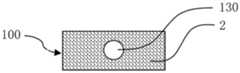
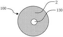
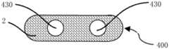
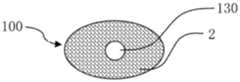
图1a为本发明所公开的第一实施例的储液元件的纵剖面图;图1b为本发明所公开的第一实施例的储液元件的横截面图。Fig. 1a is a longitudinal sectional view of the liquid storage element disclosed in the first embodiment of the present invention; Fig. 1b is a cross-sectional view of the liquid storage element disclosed in the first embodiment of the present invention.
如图1a和1b所示,根据本发明第一实施例的储液元件,用于气雾散发装置中储存和释放液体,储液元件100由双组分纤维2经热粘结形成三维网络的立体结构,双组分纤维2具有皮层21和芯层22。As shown in Figures 1a and 1b, the liquid storage element according to the first embodiment of the present invention is used for storing and releasing liquid in an aerosol dispensing device. The three-dimensional structure, the
<储液元件的形状><Shape of reservoir element>
储液元件100可以具有轴向贯穿储液元件100的储液元件通孔130。储液元件通孔130 可以用作气雾散发装置中的气雾通道。The
本实施例的储液元件100可以根据气雾散发装置的内部空间制成合适的几何形状,如适合于圆柱形气雾散发装置的圆柱形储液元件100;适合于扁形气雾散发装置的方柱形储液元件100;适合于椭圆柱形气雾散发装置的椭圆柱形储液元件100等。The
储液元件100具有轴向贯穿储液元件100的储液元件通孔130。储液元件通孔130中可以插入气雾管,如金属管、玻纤管或塑料管等,气雾可以从气雾管导出。设置气雾管可以更好地固定储液元件100,并可以在储液元件100注液时防止液体从雾化器(未图示)泄漏。The
可以将储液元件100与雾化器接触的部位压缩成较高密度,使液体在释放过程中向较高密度部位富集,从而提高液体释放的均匀性,并进一步降低使用后的液体残留。The part of the
<储液元件的密度><Density of reservoir element>
本实施例的储液元件100密度为0.03-0.25克/厘米3,如0.03克/厘米3、0.04克/厘米3、 0.050克/厘米3、0.055克/厘米3、0.065克/厘米3、0.08克/厘米3、0.10克/厘米3、0.12克/厘米3、0.15克/厘米3、0.18克/厘米3、0.21克/厘米3、0.25克/厘米3,优选为0.04-0.12克/厘米3。当密度小于0.03克/厘米3时,储液元件100制造困难,并且储液元件100的强度不足,不易在气雾散发装置中组装;当密度为0.03-0.04克/厘米3时,轴向设置通道的储液元件100的强度稍嫌不足,不太易组装;当密度大于0.15克/厘米3时,使用后期储液元件100的液体释放效率略差,使用后的液体残留偏高;当密度大于0.25克/厘米3时,单位体积储液元件100 的储液量过小,并且使用后期储液元件100的液体释放效率差,使用后的液体残留高,不利于在空间狭小的气雾散发装置中使用。The density of the
在0.04-0.12克/厘米3范围内,根据被储存液体的粘度、表面张力和应用需求,选择合适的密度,储液元件100既有足够的毛细力以防止液体泄漏,又具有良好的释放性能,并且可以使储液元件100的储液容量最大化,有利于制作小巧的气雾散发装置。值得注意的是,为防止在储存、运输和使用过程中泄漏,加载到储液元件100的液体体积最好不超过储液元件 100中毛细空隙体积的90%。In the range of 0.04-0.12 g/cm3 , according to the viscosity, surface tension and application requirements of the liquid to be stored, the appropriate density is selected, and the
为更直观地说明储液元件100的密度与使用效果的关系,本实施例制作了不同密度的储液元件100并组装了相应的气雾散发装置进行抽吸测试。雾化芯为缠绕电热丝的玻纤束。储液元件100由3旦的双组分短纤热粘结制成,皮层21为聚乙烯,芯层22为聚丙烯,储液元件100的高度为29mm,体积为1.91厘米3。储液元件100的密度分别为0.04克/厘米3,0.055 克/厘米3,0.08克/厘米3,0.12克/厘米3,0.15克/厘米3,和0.20克/厘米3,被雾化的液体为丙二醇和甘油的混合物,注液量为1.62克。用抽烟机进行测试,测试条件为:吸气3秒,停 27秒,每分钟吸气2次,每次吸气55ml,收集每抽吸50口的雾化量,每个产品重复测试20次,锂电池设计容量为400口(实际测试405-436口时电池耗尽)。数据经计算后获得每口雾化量的平均值(单位mg)、变异系数(简称CV),以及抽吸400口后的液体残留率和变异系数,结果如下:In order to more intuitively illustrate the relationship between the density of the

从测试结果可以看出,0.04-0.20克/厘米3的密度范围内,储液元件100的密度越小,抽吸过程中雾化量的衰减越小。特别是当密度为0.04-0.12克/厘米3时,前350口的雾化量相当稳定。而当密度为0.20克/厘米3时,即使前350口雾化量也存在明显衰减。一般认为抽吸过程中雾化量衰减越小,口感越稳定,用户体验越好。实验数据也显示,351-400口时雾化量衰减较多,并且CV明显偏大,这一般认为是由于锂电池即将耗尽时电压不稳定所导致。It can be seen from the test results that within the density range of 0.04-0.20 g/cm3 , the smaller the density of the
当储液元件100的密度为0.15克/厘米3时,301-350口的雾化量比1-50口的雾化量衰减了33.3%,351-400口的雾化量比1-50口的雾化量衰减了41.2%;当储液元件100的密度为 0.20克/厘米3时,301-350口的雾化量比1-50口的雾化量衰减了44.5%,351-400口的雾化量比1-50口的雾化量衰减了50.6%。在抽吸过程中,当雾化量比初始抽吸阶段降低接近50%时,一般被认为明显影响口感。When the density of the
由于毛细力的作用,抽吸结束后储液元件100中会残留一部分液体。液体的残留率越低,则液体的利用效率越高。从测试结果可以看出,0.04-0.20克/厘米3的密度范围内,储液元件 100的密度越小,抽吸400口后液体的残留率越低。当储液元件100的密度为0.04-0.12克/ 厘米3时,抽吸400口后液体的残留率低于介于16.5%-24.2%;当储液元件100的密度为0.15 克/厘米3时,抽吸400口后液体的残留率接近30%;当储液元件100的密度为0.20克/厘米3时,抽吸400口后液体的残留率超过35%,液体的利用效率不到65%,浪费较为严重。Due to the capillary force, a part of the liquid will remain in the
综合考虑抽吸过程中雾化量的稳定性和抽吸后的液体残留率,以及组装的方便性,本发明确定储液元件100优选的密度范围为0.03-0.15克/厘米3,最优选为0.04-0.12克/厘米3。Taking into account the stability of the atomization amount during the suction process, the liquid residual rate after suction, and the convenience of assembly, the present invention determines that the preferred density range of the
<双组分纤维><Bicomponent fiber>
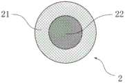
如图1a和1b所示,根据本实施例的储液元件100由双组分纤维2粘结形成三维网络的立体结构,双组分纤维2具有皮层21和芯层22。可以采用粘结剂、增塑剂或热量粘结纤维,优选用热量来粘结纤维以避免在制作储液元件100的过程中引进杂质。本发明中所说的纤维组分是指制作纤维的聚合物。用于纤维表面的添加剂,如表面活性剂,并不被认为是纤维的组分。本实施例的储液元件100能被储存的液体浸润,可以添加表面活性剂来改变储液元件 100被液体浸润的能力。As shown in FIGS. 1 a and 1 b , the
图1c是图1a和1b中的双组分纤维的一种截面放大示意图。如图1c所示,皮层21和芯层22为同心结构。同心结构的双组分纤维2刚性较大,生产方便,价格较低。Figure 1c is an enlarged schematic cross-section of the bicomponent fiber of Figures 1a and 1b. As shown in Fig. 1c, the
图1d是图1a和1b中的双组分纤维的另一种放大截面示意图。如图1d所示,皮层21和芯层22为偏心结构。偏心结构的双组分纤维2较为柔软蓬松,容易制作密度较小的储液元件100。此外,还可以采用并列结构的双组分纤维来制作储液元件100,但热粘结时比较困难。当然,还可以采用三组分的皮芯结构纤维来制作储液元件100,但三组分的皮芯结构纤维制造难度大,成本高,性价比较差。Figure 1d is another enlarged schematic cross-sectional view of the bicomponent fiber of Figures 1a and 1b. As shown in Fig. 1d, the
双组分纤维2为长丝或者短纤。长丝制成的储液元件100强度较高,短纤制成的储液元件100弹性较好。制造者可以根据储液元件100的性能要求选择合适的双组分纤维制成合适的密度和合适形状的储液元件100。The
双组分纤维2的芯层22比皮层21的熔点高25℃以上。本实施例的储液元件100由皮芯结构双组分纤维2热粘结制成。双组分纤维2的芯层22比皮层21熔点高25℃以上,可以在纤维之间进行热粘结的时候使芯层22保持一定的刚性,便于制成密度较低的储液元件100。The
皮层21为聚乙烯、聚丙烯、聚烯烃、或者共聚酯,所述芯层22为聚合物。或者,皮层21为聚乳酸,芯层22为熔点比皮层21高25℃以上的聚乳酸。The
双组分纤维2的皮层21可以为聚乙烯、聚丙烯、聚对苯二甲酸乙二醇酯的共聚酯、聚酰胺-6和聚乳酸等常见的聚合物,或者其它聚烯烃。聚烯烃为烯烃的聚合物,通常由乙烯、丙烯、1-丁烯、1-戊烯、1-己烯等α-烯烃单独聚合或共聚而得的一类热塑性树脂的总称。聚烯烃具有惰性的分子结构,分子链上不含活性基团,在本发明的应用领域中几乎不与液体成分反应,因此具有独特的优势。The
当皮层21为聚乙烯时,比如线性低密度聚乙烯、低密度聚乙烯或高密度聚乙烯,芯层 22可以为聚丙烯、聚对苯二甲酸乙二酯等聚合物。当皮层21为聚丙烯和聚烯烃时,芯层22 可以为聚对苯二甲酸乙二酯(简称PET)、聚对苯二甲酸丙二醇酯(简称PTT)或聚对苯二甲酸丁二醇酯(简称PBT)、聚酰胺等。双组分纤维2的皮层21熔化温度低,有利于提高生产效率,降低制造过程中的能耗。When the
当皮层21为聚乳酸时,根据聚乳酸的熔点,如果采用熔点约130℃的聚乳酸为皮层21,芯层22可以为聚丙烯、聚对苯二甲酸乙二酯、熔点约170℃左右的聚乳酸等。当皮层21为熔点约170℃的聚乳酸时,芯层22可以为聚对苯二甲酸乙二酯、聚对苯二甲酸丁二酯、聚对苯二甲酸丙二酯、尼龙、聚酰胺等。聚乳酸为生物降解材料,可以减少储液元件100被抛弃时造成的环境污染。尤其是当皮层21采用较低熔点的聚乳酸,芯层22采用较高熔点的聚乳酸时,制成的储液元件100为生物全降解材料。When the
<双组分纤维的纤度><The fineness of the bicomponent fiber>
制作本发明储液元件100的双组分纤维2的纤度介于1-30旦,优选1-15旦,最优选1.5-10 旦。低于1旦的皮芯结构双组分纤维2制造困难,成本高。高于30旦的纤维制成的储液元件 100毛细力不足,容易泄漏。介于1-15旦的皮芯结构双组分纤维2容易热粘结成密度较低、并且具有合适毛细力的三维立体结构的储液元件100,1.5-10旦皮芯结构双组分纤维2尤为合适,并且成本较低。The denier of the
可以将不同纤度的双组分纤维混合制成储液元件100,以优化储存和释放液体的性能或者降低成本。还可以在不影响储液元件100加工和性能的情况下在双组分纤维中掺入一些单组份纤维如聚丙烯纤维等来降低成本。The
本实施例中,优选双组分纤维2的纤度为1.5旦、2旦、3旦或6旦,皮层21为熔点约130℃的聚乙烯,芯层22为熔点约165℃的聚丙烯,储液元件100密度介于0.04-0.12克/厘米3,储液元件100具有储液容量大、不易泄漏和释放效率高等优点。In this embodiment, the fineness of the
虽然储液元件100也可以由单组份纤维,如聚丙烯纤维,用粘结剂粘结制成,但粘结剂的使用通常会使储液元件100难以符合食品或药品的相关法规,这种储液元件100不宜用于电子烟、药物雾化等气雾散发装置中。Although the
如图1a、1b、1c和1d所示,在本实施例中,储液元件100由同心结构或偏心结构的双组分纤维2经热粘结形成三维网络的立体结构。储液元件100形状为圆柱体,外径为9mm,并设置直径为3.5mm的轴向通孔为储液元件通孔130,通孔的一端与雾化器连接并将液体传导给雾化器。这种储液元件100的形状和尺寸适合于仿真烟形状的电子烟中使用,也适合在迷你型电蚊香和香薰中使用。本实施例中双组分纤维2的皮层21可以用熔点约130℃的聚乳酸代替,制成的储液元件100具有类似的性能。As shown in Figures 1a, 1b, 1c and 1d, in this embodiment, the
第二实施例Second Embodiment
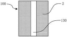
图2a为本发明所公开的第二实施例的储液元件的纵剖面图;图2b为本发明所公开的第二实施例的储液元件的横截面图。本实施例与第一实施例结构相似,与第一实施例相同的部分在本实施例的描述中不再赘述。Fig. 2a is a longitudinal sectional view of the liquid storage element according to the second embodiment disclosed in the present invention; Fig. 2b is a cross-sectional view of the liquid storage element according to the second embodiment disclosed in the present invention. The structure of this embodiment is similar to that of the first embodiment, and the same parts as those of the first embodiment will not be repeated in the description of this embodiment.
如图2a和2b所示,本实施例中,储液元件100由同心结构的双组分长丝经热粘结形成三维网络的立体结构,双组分纤维2的纤度为6旦,皮层21为熔点约165℃的聚丙烯,芯层22为熔点230℃左右的聚对苯二甲酸丁二酯,这种储液元件100具有较高的耐温性能,制成的储液元件100密度介于0.1-0.2克/厘米3,具有较大的刚性,适合于高速自动化组装。储液元件100横截面图显示的形状为长方体,设置直径3mm的轴向通孔为储液元件通孔130,通孔的一端与雾化器连接,雾化时产生的气雾经储液元件通孔130逸出,这种储液元件100的形状适合在长方体形状的扁烟中使用,也适合于电蚊香和电加热香薰中使用。本实施例中双组分纤维2的皮层21可以用熔点约170℃的聚乳酸代替,制成的储液元件100具有类似的性能。As shown in Figures 2a and 2b, in this embodiment, the
第三实施例Third Embodiment
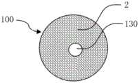
图3a为本发明所公开的第三实施例的储液元件100的纵剖面图;图3b为本发明所公开的第三实施例的储液元件100的横截面图。本实施例与第一实施例结构相似,与第一实施例相同的部分在本实施例的描述中不再赘述。Fig. 3a is a longitudinal sectional view of the
如图3a和3b所示,本实施例中,储液元件100由同心结构的双组分纤维2经热粘结形成三维网络的立体结构,双组分纤维2为短纤,其纤度为2旦,皮层21为熔点130℃的聚乳酸,芯层22为熔点155-185℃的聚乳酸,制成的储液元件100密度介于0.08-0.12克/厘米3。储液元件100横截面图显示的为椭圆形,设置直径为4mm的轴向通孔为储液元件通孔130,通孔的一端与雾化器连接,储液元件100中的液体经连接处传导给雾化器,雾化时产生的气雾经储液元件通孔130逸出,这种储液元件100的形状适合在椭圆柱形状的扁烟中使用,也可用于类似形状的电蚊香和电香薰。本实施例中的储液元件100完全由聚乳酸制成,能完全生物降解,对减少环境污染具有重要意义。As shown in FIGS. 3 a and 3 b , in this embodiment, the
第四实施例Fourth Embodiment
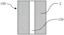
图4a为本发明所公开的第四实施例的储液元件100的纵剖面图;图4b为本发明所公开的第四实施例的储液元件100的横截面图。本实施例与第一实施例结构相似,与第一实施例相同的部分在本实施例的描述中不再赘述。Fig. 4a is a longitudinal sectional view of the
如图4a和4b所示,本实施例中,储液元件100由偏心结构的双组分纤维2经热粘结形成三维网络的立体结构,双组分纤维2为短纤,其纤度为3旦,皮层21为熔点约130℃的聚乳酸,芯层22为聚对苯二甲酸乙二酯。制成的储液元件100密度介于0.03-0.06克/厘米3,具有吸液容量大和释放残留低的特性。储液元件100为圆柱形,设置直径为4.5mm的轴向通孔为储液元件通孔130,通孔的一端与雾化器连接,雾化时产生的气雾经储液元件通孔130 逸出。As shown in Figures 4a and 4b, in this embodiment, the
本实施例中与雾化器连接部位的储液元件100被压缩形成较高密度,液体在消耗的过程中向较高密度部位富集,从而提高液体释放的均匀性并进一步降低使用后的液体残留。In this embodiment, the
优选,储液元件100被压缩形成低密度部123和高密度部124和设置在低密度部123和高密度部124之间的密度递增部125。从而液体能够更好的向高密度部124富集,可以提高液体传导的流畅性,并减少使用后在储液元件100中的液体残留。Preferably, the
这种储液元件100的形状适合在圆柱形的电子烟中使用,也适合用于电蚊香和电香薰。本实施例中双组分纤维2的皮层21可以用聚烯烃或熔点约110℃的聚对苯二甲酸乙二醇酯的共聚酯代替,制成的储液元件100具有类似的性能。The shape of the
第五实施例Fifth Embodiment
图5a为本发明所公开的第五实施例的储液元件100的纵剖面图;图5b为本发明所公开的第五实施例的储液元件100的横截面图。本实施例与第一实施例结构相似,与第一实施例相同的部分在本实施例的描述中不再赘述。Fig. 5a is a longitudinal sectional view of the
如图5a和5b所示,本实施例中,储液元件100由同心结构的双组分纤维2经热粘结形成三维网络的立体结构,双组分纤维2为长丝,其纤度为30旦,皮层21为熔点约200℃的聚对苯二甲酸乙二醇酯的共聚酯,芯层22为熔点270℃左右的聚对苯二甲酸乙二酯,这种储液元件100具有较高的耐温性能,制成的储液元件100密度介于0.15-0.25克/厘米3,储液元件100为圆柱形,设置直径5mm的轴向通孔为储液元件通孔130,通孔的一端与电加热雾化器或超声波雾化器连接,雾化时产生的气雾经储液元件通孔130逸出,这种储液元件100适合于便携式电蚊香或香薰中使用,也适合用于电子烟。本实施例中双组分纤维2的皮层21可以用熔点约170℃的聚乳酸代替,制成的储液元件100具有类似的性能。As shown in Figures 5a and 5b, in this embodiment, the
第六实施例Sixth Embodiment
图6a为本发明所公开的第六实施例的储液元件100的纵剖面图;图6b为本发明所公开的第六实施例的储液元件100的横截面图。本实施例与第一实施例结构相似,与第一实施例相同的部分在本实施例的描述中不再赘述。Fig. 6a is a longitudinal sectional view of the
如图6a和6b所示,本实施例中,储液元件100包括上下结构的储液部121和集液部122。储液部121和集液部122均具有轴向贯穿的储液元件通孔130。As shown in Figs. 6a and 6b, in this embodiment, the
储液部121由偏心结构的双组分纤维2经热粘结形成三维网络的立体结构,双组分纤维 2的纤度为3旦,皮层21为熔点约130℃的聚乙烯,芯层22为熔点165℃左右的聚丙烯,储液部121密度介于0.04-0.08克/厘米3,储液部121为圆柱形。制成集液部122的双组分纤维 2与制成储液部的纤维相同,储液部121和集液部122均设置直径4mm的轴向通孔为储液元件通孔130,通孔的一端与电加热雾化器或超声波雾化器连接,雾化时产生的气雾经储液元件通孔130逸出,这种储液元件100适合于便携式电蚊香或香薰中使用,也适合用于电子烟。本实施例中双组分纤维2的皮层21可以用熔点约130℃的聚乳酸代替,制成的储液元件100 具有类似的性能。The
本实施例中,集液部122的密度高于储液部121。由于集液部122的密度高于储液部121,使液体在消耗的过程中向较高密度的集液部122富集,从而提高液体释放的均匀性并进一步降低使用后的液体残留。In this embodiment, the density of the
第七实施例Seventh Embodiment
图7a为本发明所公开的第七实施例的储液元件100的纵剖面图;图7b为本发明所公开的第七实施例的储液元件100的横截面图。本实施例与第一实施例结构相似,与第一实施例相同的部分在本实施例的描述中不再赘述。Fig. 7a is a longitudinal sectional view of the
如图7a和7b所示,本实施例中,储液元件100包括集液部122和包覆在集液部122外周壁上的密度低于集液部122的储液部121。集液部122具有轴向贯穿集液部122的储液元件通孔130。As shown in FIGS. 7 a and 7 b , in this embodiment, the
储液部121由同心结构的双组分纤维2经热粘结形成三维网络的立体结构,双组分纤维 2的纤度为3旦,皮层21为熔点约130℃的聚乳酸,芯层22为熔点270℃左右的聚对苯二甲酸乙二酯,储液部121密度介于0.1-0.15克/厘米3,储液部121为圆柱形。集液部122由同心结构的双组分纤维2经热粘结形成三维网络的立体结构,双组分纤维2的纤度为2旦,皮层为熔点约170℃的聚乳酸,芯层为熔点270℃左右的聚对苯二甲酸乙二酯,设置直径5mm 的轴向通孔为气雾通道,通孔的一端与电加热雾化器或超声波雾化器连接,雾化时产生的气雾经储液元件通孔130逸出,这种储液元件100适合于便携式电蚊香或香薰中使用,也适合用于电子烟。The
本实施例中,集液部122的密度高于储液部121。由于集液部122的密度高于储液部121,使液体在消耗的过程中向较高密度的集液部122富集,从而提高液体释放的均匀性并进一步降低使用后的液体残留。In this embodiment, the density of the
综上,本发明涉及的用于气雾散发装置的储液元件100采用了皮芯结构的双组分纤维制成并在轴向设置气雾通道,气雾通道由储液元件100中的储液元件通孔130形成。本发明的储液元件100能广泛应用于各类将液体气化或雾化的气雾散发装置中来储存和释放液体,在简化气雾散发装置结构的同时巧妙地具有导出气雾的功能,提高使用者体验。储液元件100 根据应用需求能在热粘结过程中制成需要的三维结构的尺寸和形状,从而适合高速的自动化组装,以降低电子烟、药物雾化、电蚊香和电香薰等气雾散发装置的制造成本。上述实施例仅例示性说明本发明的原理及其功效,而非用于限制本发明,任何本领域技术人员皆可在不违背本发明的精神及范畴下,对上述实施例进行修饰或改变。因此,本领域技术人员在未脱离本发明所揭示的精神与技术思想下所完成的一切等效修饰或改变,仍应由本发明的权利要求所涵盖。To sum up, the
第八实施例Eighth Embodiment
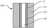
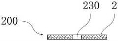
图8a为本发明所公开的第八实施例的导液元件的纵剖面图;图8b为本发明所公开的第八实施例的导液元件的横截面图;图8c是图8a和8b中的双组分纤维的一种截面放大示意图;图8d是图8a和8b中的双组分纤维的另一种截面放大示意图。Fig. 8a is a longitudinal sectional view of the liquid-conducting element disclosed in the eighth embodiment of the present invention; Fig. 8b is a cross-sectional view of the liquid-conducting element disclosed in the eighth embodiment of the present invention; An enlarged schematic cross-section of the bicomponent fiber of FIG. 8d is another enlarged schematic cross-section of the bicomponent fiber in FIGS. 8a and 8b.
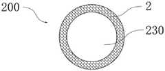
如图8a至8d所示,根据本发明第八实施例的导液元件200,用于气雾散发装置中传导液体,导液元件200由双组分纤维2经热粘结形成三维网络的立体结构,双组分纤维2具有皮层21和芯层22。As shown in Figures 8a to 8d, the
<导液元件的形状、厚度、刚性和液体渗透的速度><The shape, thickness, rigidity and speed of liquid penetration of the liquid-conducting element>
导液元件200可以具有轴向贯穿导液元件200的导液元件通孔230。The
本实施例的导液元件200,根据气雾散发装置的设计,可以把导液元件200设计为片状或者管状。如图1a和图1b所示,本实施例中的导液元件200设置为管状。In the
导液元件200也可以设计为片状。片状的导液元件200也可以设置导液元件通孔230。The liquid-conducting
根据气雾散发装置的结构,可以把导液元件200的横截面制成圆环状、椭圆环状或其它需要的形状。According to the structure of the aerosol dispersing device, the cross-section of the
对于片状导液元件200,本文中轴向定义为其厚度方向,径向定义为与厚度垂直的方向。采用适当的制作技术,可以使纤维在导液元件200中具有较多的轴向排列取向,这种情况下,片状导液元件200的轴向刚性大于其径向刚性,导液元件200中液体沿轴向渗透的速度大于液体沿径向渗透的速度;也可以使纤维在导液元件200中具有较多的径向排列的取向,这种情况下,片状导液元件200的径向刚性大于其轴向刚性,导液元件200中液体沿径向渗透的速度大于液体沿轴向渗透的速度。For the sheet-like liquid-conducting
对管状导液元件200,本文中轴向定义为导液元件通孔230的中轴线的方向,径向定义为与导液元件通孔230的中轴线垂直的方向。管状导液元件200中纤维具有较多的轴向排列取向,导液元件200的轴向刚性大于其径向刚性,导液元件200中液体沿轴向渗透的速度大于液体沿径向渗透的速度。For the tubular
本文中的刚性的比较方法是:将导液元件200沿轴向或者径向放置,夹持在两块平行的板之间,测量未压缩前的导液元件200的轴向高度或者径向高度;在施加同样作用力的情况下,测量两块板轴向或者径向压缩导液元件200后的轴向高度或者径向高度,并计算压缩的变形量,该压缩的变形量为未压缩前的轴向高度或者径向高度减去压缩后的轴向高度或者径向高度后的差值;将压缩的变形量除以未压缩前的导液元件200的轴向高度或者径向高度,获得压缩比。压缩比越小,则刚性越大,压缩比越大,则刚性越小。The rigidity comparison method in this paper is to place the fluid-conducting
导液元件200的厚度是指液体从导液元件200一侧传导到另一侧的最短距离,管状导液元件200的厚度为管壁的厚度,片状导液元件200的厚度为其厚度方向上的厚度。The thickness of the
导液元件200的厚度为0.3mm-3mm,优选0.6mm,0.9mm,1.2mm,1.5mm,2mm。当导液元件200的厚度小于0.3mm时,难以制作均匀的导液元件200,也不方便安装。当导液元件200的厚度大于3mm时,导液元件200在气雾散发装置中占过多的空间,尤其对管状导液元件200,厚度大于3mm时通常难以在细小的气雾散发装置中安装。另外,厚度大于3mm 时,导液元件200吸收液体量过多,影响液体的利用效率。The thickness of the
<导液元件的密度><Density of liquid-conducting element>
本实施例的导液元件200的密度为0.05-0.35克/厘米3,优选为0.1-0.3克/厘米3。当密度小于0.05克/厘米3时,导液元件200的强度不足,管状导液元件200与气雾散发装置装配时容易变形甚至褶皱,影响雾化的稳定性,严重时甚至造成漏液。当密度大于0.35克/厘米3时,导液速度较慢,影响雾化效率,并且高密度的导液元件的硬度过高,径向弹性不足,管状导液元件与气雾散发装置的匹配性下降。The density of the
<双组分纤维><Bicomponent fiber>
图8c是图8a和8b中的双组分纤维的一种放大截面示意图。如图8c所示,皮层21和芯层22为同心结构。图8d是图8a和8b中的双组分纤维的另一种放大截面示意图。如图8d 所示,皮层21和芯层22为偏心结构。由同心结构的双组分纤维2制成的导液元件刚性较大,由偏心结构的双组分纤维2制成的导液元件200弹性较好。Figure 8c is an enlarged schematic cross-sectional view of the bicomponent fiber of Figures 8a and 8b. As shown in Fig. 8c, the
双组分纤维2为长丝或者短纤。长丝制成的导液元件200刚性较大,短纤制成的导液元件200弹性较好。可以根据导液元件200的性能要求选择双组分纤维制成合适的导液元件200。The
双组分纤维2的芯层22比皮层21的熔点高20℃以上。本实施例的导液元件200由皮芯结构双组分纤维2热粘结制成。双组分纤维2的芯层22比皮层21熔点高20℃以上,可以在纤维之间进行热粘结的时候使芯层22保持一定的刚性,便于制成空隙均匀的导液元件200。The
双组分纤维2的皮层21可以为聚烯烃、聚对苯二甲酸乙二醇酯的共聚酯、聚对苯二甲酸丙二醇酯、聚对苯二甲酸丁二醇酯、聚乳酸或者聚酰胺-6。聚烯烃为烯烃的聚合物,通常由乙烯、丙烯、1-丁烯、1-戊烯、1-己烯等α-烯烃单独聚合或共聚而得的一类热塑性树脂的总称。也可以为聚酯或低熔点共聚酯等常见的聚合物。The
当皮层21为聚乙烯时,芯层22可以为聚丙烯、聚对苯二甲酸乙二醇酯(简称PET)等聚合物。当皮层21为聚丙烯时,芯层22可以为PET、聚酰胺等。双组分纤维2的皮层21熔点较低,有利于提高生产效率,降低制造成本。双组分纤维2的皮层21熔点较高,导液元件有较高的耐温性能,有利于提高雾化芯的工作温度。When the
当皮层21为聚乳酸时,根据聚乳酸的熔点,比如用熔点125-135℃的聚D,L-乳酸为皮层21,芯层22可以为聚丙烯、聚对苯二甲酸乙二醇酯、熔点155-180℃的聚L-乳酸或聚D-乳酸等。当皮层21为熔点145-180℃的聚D-乳酸或聚L-乳酸时,芯层22可以为聚对苯二甲酸乙二醇酯、聚对苯二甲酸丁二醇酯(简称PBT)、聚对苯二甲酸丙二醇酯(简称PTT)、聚酰胺等。聚乳酸为生物降解材料,可以减少导液元件被抛弃时造成的环境污染。When the
当皮层21为聚酯或共聚酯时,可以根据皮层21的熔点选择合适的芯层22。比如皮层21 用熔点225-235℃的PBT或PTT,芯层22可以用熔点255-265℃的PET。再比如皮层为熔点为110-120℃或160-200℃的聚对苯二甲酸乙二醇酯的共聚酯(简称Co-PET),芯层可以用PET、PBT或PTT。When the
制作本发明导液元件200的双组分纤维2的纤度介于1-30旦,优选1.5-10旦。低于1旦的皮芯结构双组分纤维2制造困难,成本高。高于30旦的纤维制成的导液元件200毛细力不足,导液较差。介于1-30旦的皮芯结构双组分纤维2容易制作导液元件200,1.5-10旦皮芯结构双组分纤维2尤为合适,并且成本较低。被雾化的液体粘度较低时,宜采用纤度较小的纤维制作导液元件,如采用1旦、1.5旦、2旦、3旦的纤维。被雾化的液体粘度较高时,宜采用纤度较大的纤维制作导液元件,如采用6旦、10旦、30旦的纤维。The fineness of the
如图8a、8b、8c和8d所示,在本实施例中,优选导液元件200由同心结构的双组分短维2经热粘结形成三维网络的管状立体结构。皮层21为熔点125-135℃的聚乙烯,芯层22 为熔点160-170℃的聚丙烯,制成的导液元件200密度介于0.05-0.35克/厘米3,这种导液元件200具有较好的轴向强度和较好的径向弹性,并具有较快的液体传导速度。这种导液元件200可以用于电子烟烟液的雾化,也适合在迷你型电蚊香和香薰中使用。As shown in Figures 8a, 8b, 8c and 8d, in this embodiment, preferably, the
本实施例中双组分纤维2的皮层21用熔点160-170℃的聚丙烯替代时,双组分纤维2的芯层可以用PET、PBT、PTT、聚酰胺等,制成的导液元件200具有较高的耐温性能。还可以用PBT或PTT作为皮层,用PET为芯层制成耐温更高的导液元件200。In this embodiment, when the
在本实施例中的另一优选方式中,导液元件200由偏心结构的双组分纤维经热粘结形成三维网络的管状结构。导液元件200的皮层21为聚乙烯,芯层22为聚丙烯或PET,制成的导液元件200厚度为0.3-0.8mm,密度介于0.1-0.3克/厘米3。In another preferred mode of this embodiment, the liquid-conducting
第九实施例Ninth Embodiment
图9a为本发明所公开的第九实施例的导液元件的纵剖面图;图9b为本发明所公开的第九实施例的导液元件为圆柱体时的横截面图;图9c为本发明所公开的第九实施例的导液元件为长方体时的横截面图;图9d为本发明所公开的第九实施例的导液元件为椭圆柱体时的横截面图。本实施例与第八实施例结构相似,与第八实施例相同的部分在本实施例的描述中不再赘述。Fig. 9a is a longitudinal sectional view of the liquid conducting element disclosed in the ninth embodiment of the present invention; Fig. 9b is a cross-sectional view of the liquid conducting element disclosed in the ninth embodiment of the present invention when it is a cylinder; Fig. 9c is a A cross-sectional view of the liquid conducting element disclosed in the ninth embodiment of the present invention is a rectangular parallelepiped; FIG. 9d is a cross-sectional view of the liquid conducting element disclosed in the ninth embodiment of the present invention when the liquid conducting element is an elliptical cylinder. The structure of this embodiment is similar to that of the eighth embodiment, and the same parts as those of the eighth embodiment will not be repeated in the description of this embodiment.
本实施例中,导液元件200为片状,由同心结构的双组分纤维2经热粘结形成三维网络的片状结构。导液元件200的厚度为0.8-1.5mm,中心设置导液元件通孔230。导液元件200 的皮层21为熔点125-135℃的聚D,L-乳酸,芯层22为熔点155-180℃的聚L-乳酸或聚D-乳酸,制成的导液元件200密度介于0.2-0.3克/厘米3,这种导液元件200为生物降解材料,可以减少导液元件200被抛弃时造成的环境污染。In this embodiment, the liquid-conducting
本实施例中,片状导液元件200的径向刚性大于其轴向刚性,导液元件200中液体沿径向渗透的速度大于液体沿轴向渗透的速度。In this embodiment, the radial rigidity of the sheet-shaped liquid-conducting
如图9b、9c和9d所示,根据气雾散发装置的结构,可以把导液元件200分别设计为圆柱体、方柱体和椭圆柱体,对应的横截面分别为圆环状、方形环状、椭圆环状。也可以根据需要设计为其它需要的形状。As shown in Figures 9b, 9c and 9d, according to the structure of the aerosol dispersing device, the
第十实施例Tenth Embodiment
图10a为本发明所公开的第十实施例的导液元件的纵剖面图;图10b为本发明所公开的第十实施例的导液元件为圆柱体时的横截面图;图10c为本发明所公开的第十实施例的导液元件为长方体时的横截面图;图10d为本发明所公开的第十实施例的导液元件为椭圆柱体时的横截面图。本实施例与第八实施例结构相似,与第八实施例相同的部分在本实施例的描述中不再赘述。Fig. 10a is a longitudinal sectional view of the liquid conducting element disclosed in the tenth embodiment of the present invention; Fig. 10b is a cross-sectional view of the liquid conducting element disclosed in the tenth embodiment of the present invention when it is a cylinder; Fig. 10c is a The cross-sectional view of the liquid guiding element disclosed in the tenth embodiment of the present invention is a rectangular parallelepiped; FIG. 10d is a cross-sectional view of the liquid guiding element of the tenth embodiment disclosed in the present invention when the liquid guiding element is an elliptical cylinder. The structure of this embodiment is similar to that of the eighth embodiment, and the same parts as those of the eighth embodiment will not be repeated in the description of this embodiment.
在本实施例中,导液元件200为片状,中心不设置导液元件通孔230,且由偏心结构的双组分纤维2经热粘结形成三维网络的结构。皮层21为熔点145-180℃的聚D-乳酸或聚L-乳酸,芯层22为熔点255-265℃的PET,制成的导液元件200密度介于0.25-0.35克/厘米3,厚度为3mm。这种导液元件200具有较高的导液速度。本实施例中双组分纤维的皮层可以用Co-PET代替以降低成本,或用PBT或PTT代替,使导液元件200具有更好的耐温性能。In this embodiment, the liquid-conducting
在本实施例中,导液元件200的轴向刚性大于其径向刚性,导液元件200中液体沿轴向渗透的速度大于液体沿径向渗透的速度。In this embodiment, the axial rigidity of the
本实施例中,也可以是,导液元件200由同心结构的双组分纤维经热粘结形成三维网络的片状结构,厚度为1.5-2mm。导液元件的皮层21为PBT或PTT,芯层22为PET,制成的导液元件200密度介于0.25-0.35克/厘米3。优选,该片状导液元件的径向刚性大于其轴向刚性,导液元件中液体沿径向渗透的速度大于液体沿轴向渗透的速度。In this embodiment, the liquid-conducting
如图10b、10c和10d所示,根据气雾散发装置的结构,可以把导液元件200分别设计为圆柱体、方柱体和椭圆柱体,对应的横截面分别为圆形、矩形和椭圆形。也可以根据需要设计为其它需要的形状。As shown in Figures 10b, 10c and 10d, according to the structure of the aerosol dispersing device, the
综上,本发明涉及的用于气雾散发装置的导液元件由双组分纤维粘结制成,能广泛应用于各类气雾散发装置。导液元件具有较好的强度,适合自动化组装,大幅提高气雾散发装置的生产效率。导液元件能平稳快速地将液体传导给雾化芯,提高雾化效率和稳定性。上述实施例仅例示性说明本发明的原理及其功效,而非用于限制本发明。任何本领域技术人员皆可在不违背本发明的精神及范畴下,对上述实施例进行修饰或改变。因此,本领域技术人员在未脱离本发明所揭示的精神与技术思想下所完成的一切等效修饰或改变,仍应由本发明的权利要求所涵盖。To sum up, the liquid-conducting element used in the aerosol dispensing device according to the present invention is made by bonding two-component fibers, and can be widely used in various aerosol dispensing devices. The liquid-conducting element has good strength, is suitable for automatic assembly, and greatly improves the production efficiency of the aerosol emission device. The liquid-conducting element can smoothly and quickly conduct the liquid to the atomizing core, which improves the atomization efficiency and stability. The above-mentioned embodiments merely illustrate the principles and effects of the present invention, but are not intended to limit the present invention. Any person skilled in the art can modify or change the above embodiments without departing from the spirit and scope of the present invention. Therefore, all equivalent modifications or changes made by those skilled in the art without departing from the spirit and technical idea disclosed in the present invention should still be covered by the claims of the present invention.
第十一实施例Eleventh Embodiment
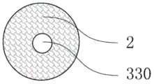
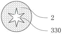
图11a是根据本发明第十一实施例的冷却元件的纵剖面图;图11b是根据本发明第十一实施例的冷却元件的一种横截面图;图11c是图11a和11b中的双组分纤维的一种截面放大示意图;图11d是图11a和11b中的双组分纤维的另一种截面放大示意图;图11e是根据本发明第十一实施例的冷却元件的另一种横截面图。Fig. 11a is a longitudinal sectional view of a cooling element according to an eleventh embodiment of the present invention; Fig. 11b is a cross-sectional view of a cooling element according to an eleventh embodiment of the present invention; An enlarged schematic cross-sectional view of a component fiber; Figure 11d is another schematic cross-sectional enlarged schematic view of the bicomponent fiber in Figures 11a and 11b; Figure 11e is another cross-sectional view of a cooling element according to an eleventh embodiment of the present invention. Sectional view.
如图11a至图11e所示,根据本发明第十一实施例的冷却元件,用于冷却气雾散发装置中产生的气雾,冷却元件300由双组分纤维2经热粘结形成三维网络的立体结构,双组分纤维材料2具有皮层21和芯层22。As shown in FIGS. 11 a to 11 e , the cooling element according to the eleventh embodiment of the present invention is used for cooling the aerosol generated in the aerosol dispersing device, and the
本实施例适用于各种气雾散发装置,如加热不燃烧型的气雾散发装置和雾化型的气雾散发装置。气雾散发装置中包括气雾基体,气雾基体中含有气雾剂,如丙二醇、甘油、水等。气雾基体还可以包括载体,如烟草、中草药、纤维、纸屑等等。传统的卷烟燃烧时高达800℃左右的温度将烟草中的大部分水分蒸发掉,气雾相对干燥,使用者吸入气雾时感知的温度较低。不同的是,气雾散发装置加热时的温度较低,只有200-400℃,产生的气雾中可能含有较高的水分,并含有气化的气雾剂,如丙二醇、甘油等,使用者吸入这种气雾时感知的温度较高。因此将气雾冷却至使用者感觉舒服的温度并去除冷凝液是气雾散发装置的一个重要考量。This embodiment is applicable to various aerosol emission devices, such as heat-not-burn-type aerosol emission devices and atomization-type aerosol emission devices. The aerosol dispensing device includes an aerosol base, and the aerosol base contains aerosols, such as propylene glycol, glycerin, water, and the like. Aerosol substrates may also include carriers such as tobacco, herbal medicine, fibers, paper scraps, and the like. When a traditional cigarette is burned, the temperature as high as about 800°C evaporates most of the moisture in the tobacco, the aerosol is relatively dry, and the user perceives a lower temperature when inhaling the aerosol. The difference is that the heating temperature of the aerosol emitting device is low, only 200-400 ° C, and the generated aerosol may contain high moisture and vaporized aerosols, such as propylene glycol, glycerin, etc. The perceived temperature is higher when inhaling this aerosol. Therefore, cooling the aerosol to a temperature comfortable for the user and removing the condensate is an important consideration for the aerosol dispensing device.
在雾化类的气雾散发装置中,气雾基体也可以为加载气雾剂的储液元件。在此种情形下,气雾基体891中的气雾剂通过加热元件(未图示)加热后雾化并通过冷却元件300冷却后逸出。同时,冷却元件300兼具吸收气雾中的冷凝液的功能,使得使用者吸入气雾时感知的温度适中,且基本不包含冷凝液,提升口感和体验。In the atomization type aerosol distributing device, the aerosol substrate can also be a liquid storage element loaded with aerosol. In this case, the aerosol in the aerosol matrix 891 is heated by the heating element (not shown) and then atomized and cooled by the
<冷却元件的孔隙率><Porosity of Cooling Element>
根据本实施例的冷却元件300由双组分纤维热粘结制成,可以制成不同的孔隙率。在本实施例中,冷却元件300的孔隙率可以设置为65%-95%,优选孔隙率为75-85%。The
孔隙率大于95%时,冷却元件300成型困难并且硬度不足。孔隙率小于65%时,冷却元件300硬度过大,或成本过高,不适合在气雾散发装置中使用。When the porosity is greater than 95%, the
<冷却元件的结构><Structure of cooling element>
根据本实施例的冷却元件300,可以根据需要制成各种结构,如图11a至11c所示,冷却元件300可以设置为中空的结构,即冷却元件300可以具有轴向贯穿冷却元件300的冷却元件通孔330。According to the
如图11b所示,冷却元件300可以设置为冷却元件通孔330截面为圆形的中空结构,冷却元件300的横截面形状为圆环。也可以如图11e所示,冷却元件300可以设置为冷却元件通孔330截面为星形的中空结构,冷却元件300的横截面形状为星形环,冷却元件通孔330的截面可以为五角星形、六角星形等。As shown in FIG. 11 b , the
在制作冷却元件300时,中空的冷却元件300和非中空的冷却元件300可以单独使用,也可以组合使用,以达到适当的冷却效果并控制合适的气阻。When manufacturing the
本实施例中,采用中空结构的冷却元件300,可以降低气雾穿过冷却元件300的阻力,从而使高温气雾在气阻低的中空通道通过,中空通道内表面与高温气雾接触时,双组分纤维 2的皮层21从高温气雾中吸收大量热量而熔化,使气雾温度迅速降低。当高温气雾主要从中空通道通过时,冷却元件300的外周与高温气雾距离较远,温度传递至外周时已经降至较低温度,从而避免冷却元件300的外周壁因高温而发生形变或损坏气雾散发装置的结构和性能。In this embodiment, the use of the
<双组分纤维><Bicomponent fiber>
如图11c和11d所示,本发明的冷却元件300由双组分纤维2经热粘结形成三维网络的立体结构,双组分纤维2具有皮层21和芯层22。As shown in FIGS. 11 c and 11 d , the
图11c是图11a和11b中的双组分纤维的一种截面放大示意图。如图11c所示,皮层21和芯层22为同心结构。图11d是图11a和11b中的双组分纤维的另一种截面放大示意图,如图11d所示,皮层21和芯层22为偏心结构。密度相同时,由同心结构的双组分纤维2制成的冷却元件300刚性较大,由偏心结构的双组分纤维2制成的冷却元件300弹性较好。Figure 11c is an enlarged schematic cross-sectional view of the bicomponent fibers of Figures 11a and 11b. As shown in Fig. 11c, the
双组分纤维2为长丝或者短纤。长丝制成的冷却元件300轴向刚性较大,短纤制成的冷却元件300径向弹性较好。可以根据冷却元件300的性能要求选择双组分纤维制成合适的冷却元件300。The
双组分纤维2的皮层21可以为聚乙烯、聚丙烯等聚烯烃、或对苯二甲酸乙二醇酯的共聚酯、聚对苯二甲酸丙二酯、聚对苯二甲酸丁二酯、聚D-乳酸、聚L-乳酸、聚D,L-乳酸、或者聚酰胺-6等。聚烯烃为烯烃的聚合物,通常由乙烯、丙烯、1-丁烯、1-戊烯、1-己烯等α-烯烃单独聚合或共聚而得的一类热塑性树脂的总称。聚烯烃具有惰性的分子结构,分子链上不含活性基团,在本发明的应用领域中几乎不与液体成分反应,因此具有独特的优势。The
当皮层21为聚乙烯时,芯层22可以为聚丙烯、聚对苯二甲酸乙二酯等聚合物。当皮层21 为聚丙烯时,芯层22可以为聚对苯二甲酸乙二酯、聚酰胺等。双组分纤维2的皮层21熔点较低,有利于提高生产效率,降低制造成本。双组分纤维2的皮层21熔点较高,同时采用更高熔点的芯层22,制作的高温冷却段能耐受更高温度的气雾。When the
当皮层21为聚乳酸时,根据聚乳酸的熔点,如果采用熔点约130℃的聚乳酸为皮层21,芯层22可以为聚丙烯、聚对苯二甲酸乙二酯、熔点170℃左右的聚乳酸等。当皮层21为熔点 150-185℃的聚乳酸时,芯层22可以为聚对苯二甲酸乙二酯、聚对苯二甲酸丁二酯、聚对苯二甲酸丙二酯、聚酰胺等。聚乳酸为生物降解材料,可以减少冷却元件300被抛弃时造成的环境污染。When the
制作本发明冷却元件300的双组分纤维2的纤度介于1-30旦,优选1.5-10旦,1.5-10旦的双组分纤维制造方便、成本较低,并且制成的冷却元件具有较大的毛细力,能更好地吸收并去除气雾中的冷凝液而形成干燥的气雾,有利于使用者感知到较低的温度。The fineness of the
在本实施例中,双组分纤维2为长丝或短纤,具有同心结构的皮层21和芯层22,皮层21 为聚对苯二甲酸乙二醇酯的共聚酯,芯层22为聚对苯二甲酸乙二酯。In this embodiment, the
双组分纤维2的皮层21为熔点较高,能耐更高的气雾温度,如某些中药气雾散发装置,工作时加热元件的温度高达400℃或以上。若气雾散发装置工作时的温度较低,如雾化电子烟或加热不燃烧电子烟,可以用熔点较低的聚合物如聚丙烯、或聚L-乳酸等作为双组分纤维2 的皮层21。The
<冷却元件的工作原理><How the cooling element works>
根据本实施例的冷却元件300,用于冷却气雾散发装置中产生的气雾。气雾散发装置产生的气雾通过冷却元件300被适当地冷却。气雾通过热交换把自身的热量传导给冷却元件300 而降低温度,冷却元件300吸收气雾中的热量后温度升高,冷却元件300中的物质在吸收热量后部分熔化,则可以吸收气雾中的大量热量,使气雾的温度显著降低。The
本实施例中的冷却元件300由双组分纤维2粘结制成,双组分纤维2的皮层21和芯层22 均为聚合物,聚合物发生某些相变时可以吸收热量,如聚合物熔化时晶区被破坏,从固态转变为黏流态,这种相变过程需要从外界吸收大量的热量。The
在应用了根据本实施例的冷却元件300的气雾散发装置中,气雾散发装置中产生的气雾,温度高于双组分纤维的皮层熔点。高温气雾从冷却元件300的一端流入并从其另一端逸出,冷却元件300的双组分纤维的皮层接触高温气雾时熔化,从而吸收气雾中的大量热量,使高温气雾的温度迅速降低。In the aerosol emission device to which the
在本实施例中,冷却元件300的双组分纤维2的芯层22的熔点比皮层21的熔点高25℃以上,双组分纤维2中的高熔点芯层22担当骨架,熔化的皮层21成为黏流态并附着于芯层22上,从而保持冷却元件300的完整性。In this embodiment, the melting point of the
根据应用要求对冷却元件300进行设计,可以使气雾从冷却元件300的另一端逸出时的温度降至65℃以下,以适合抽吸者的口感。The
<冷却元件的附加功能><Additional function of cooling element>
气雾从冷却元件300的一端流入并从其另一端逸出的过程中,温度逐渐下降,部分气化的气雾剂和水分冷凝成小液滴。由双组分纤维2粘结制成的冷却元件300具有大量的毛细孔,毛细孔能吸收气雾冷却时产生的冷凝液,使气雾变得干燥,有利于使用者感知到较低的温度。冷凝液可以吸收部分的酚类和醛类物质,因此冷却元件300的毛细孔吸收冷凝液的同时还能减少气雾中的酚类和醛类等有害物质。As the aerosol flows in from one end of the
可以在冷却元件中添加减少酚类物质的添加剂,比如甘油醋酸酯、柠檬酸三乙酯、低分子量乙二醇,以及甘油醋酸酯和醋酸纤维素纤维的混合物等。还可以在冷却元件中添加风味剂,如薄荷、天然或合成香精等,使使用者可以吸入具有不同风味的气雾。Additives to reduce phenolics such as glycerol acetate, triethyl citrate, low molecular weight ethylene glycol, and mixtures of glycerol acetate and cellulose acetate fibers can be added to the cooling element. Flavoring agents, such as mint, natural or synthetic flavors, etc., can also be added to the cooling element, allowing the user to inhale aerosols with different flavors.
第十二实施例Twelfth Embodiment
图12a是根据本发明第十二实施例的冷却元件的纵剖面图;图12b是根据本发明第十二实施例的冷却元件的横截面图。本实施例与第十一实施例结构相似,与第十一实施例相同的部分在本实施例的描述中不再赘述。Fig. 12a is a longitudinal cross-sectional view of a cooling element according to a twelfth embodiment of the present invention; Fig. 12b is a cross-sectional view of a cooling element according to a twelfth embodiment of the present invention. This embodiment is similar in structure to the eleventh embodiment, and the same parts as the eleventh embodiment will not be repeated in the description of this embodiment.
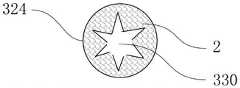
在本实施例中,冷却元件300包括轴向贯穿冷却元件300的冷却元件通孔330。冷却元件通孔330的截面设置为星形,并且,如图2b所示,在冷却元件通孔330中插入内芯331。内芯331优选圆柱体结构,由于在星形的中空结构和圆柱体内芯331之间形成多个气流通道,使气雾通过冷却元件300时分成数股小气流,从而更充分地与冷却元件300接触并进行热交换。In the present embodiment, the
第十三实施例Thirteenth Embodiment
图13a是根据本发明第十三实施例的冷却元件的纵剖面图;图13b是根据本发明第十三实施例的冷却元件的高温冷却段的一种横截面图;图13c是根据本发明第十三实施例的冷却元件的高温冷却段的另一种横截面图;图13d是根据本发明第十三实施例的冷却元件的低温冷却段的横截面图。本实施例与第十一实施例结构相似,与第十一实施例相同的部分在本实施例的描述中不再赘述。Fig. 13a is a longitudinal sectional view of a cooling element according to a thirteenth embodiment of the present invention; Fig. 13b is a cross-sectional view of a high temperature cooling section of a cooling element according to a thirteenth embodiment of the present invention; Fig. 13c is a cross-sectional view of the cooling element according to the present invention Another cross-sectional view of the high temperature cooling section of the cooling element of the thirteenth embodiment; Figure 13d is a cross-sectional view of the low temperature cooling section of the cooling element according to the thirteenth embodiment of the present invention. This embodiment is similar in structure to the eleventh embodiment, and the same parts as the eleventh embodiment will not be repeated in the description of this embodiment.
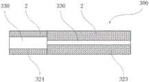
如图13a至13d所示,冷却元件300包括高温冷却段324和低温冷却段323。在应用了根据本实施例的冷却元件300的气雾散发装置中,气雾散发装置中产生的气雾,从冷却元件300 的高温冷却段324的端部流入,并从低温冷却段323的端部逸出。As shown in Figures 13a to 13d, the
如图13b所示,冷却元件300的高温冷却段324具有轴向贯穿高温冷却段324的冷却元件通孔330。高温冷却段324优选设置为冷却元件通孔330截面为圆形的中空结构,其横截面形状为圆环。也可以如图13d所示,冷却元件300的高温冷却段324可以设置为冷却元件通孔330截面为星形的中空结构,其横截面形状为星形环,即中空结构的内孔的截面形状可以为五角星形、六角星形等。高温冷却段324采用中空结构,可以降低气雾穿过高温冷却段324的阻力,从而使高温气雾在气阻低的中空通道通过,中空通道内表面与高温气雾接触时,双组分纤维2的皮层21从高温气雾中吸收大量热量而熔化,使气雾温度迅速降低。当高温气雾主要从中空通道通过时,高温冷却段324的外周与高温气雾距离较远、温度传递至外周时已经降至较低温度,从而避免高温冷却段324的外周壁因高温而发生形变或损坏气雾散发装置的结构和性能。As shown in FIG. 13 b , the high
在本实施例中,冷却元件300的高温冷却段324由双组分纤维热2粘结制成,高温冷却段 324的孔隙率优选为80%,双组分纤维2为短纤,具有同心结构的皮层21和芯层22。In this embodiment, the high-
如图13c所示,本实施例中低温冷却段323采用非中空结构,低温冷却段323的横截面形状为实心圆面。低温冷却段323的孔隙率为90-95%,由偏心结构的双组分纤维2粘结制成。虽然低温冷却段323为非中空结构,但由于低温冷却段323的孔隙率高,仍具有较低的气阻。As shown in FIG. 13c , in this embodiment, the low-
气雾经过高温冷却段324冷却后,温度较低的气雾进入低温冷却段323。低温冷却段323 与气雾进行热交换,低温冷却段323吸收热量温度升高,气雾将热量传导给低温冷却段323 后温度进一步降低。若经过高温冷却段324冷却后的气雾温度高于低温冷却段323的双组分纤维2的皮层21的熔点,则低温冷却段323的双组分纤维2的皮层21会被部分熔化,使气雾温度迅速下降。根据应用要求对冷却元件300进行设计,可以使气雾从低温冷却段323的端面逸出时的温度降至65℃以下,以适合抽吸者的口感。采用非中空结构的低温冷却段323,气雾穿透低温冷却段323时,能与双组分纤维2进行更充分的热交换,能更好地降低气雾温度。After the aerosol is cooled by the high
在本实施例中,优选,高温冷却段324的皮层21的熔点大于低温冷却段323的皮层21 的熔点。在高温冷却段324的双组分纤维2中,皮层21为熔点约170℃的聚L-乳酸,芯层22为熔点约265℃的聚对苯二甲酸乙二酯。在低温冷却段323的双组分纤维2中,皮层21为熔点约130℃的聚D,L-乳酸,芯层22为熔点约170℃的聚L-乳酸。In this embodiment, preferably, the melting point of the
如果应用本实施例的冷却元件300的气雾散发装置载有尼古丁和甘油等成份,当气雾散发装置加热至375℃左右时,尼古丁和甘油等成份挥发并随着用户抽吸从产生气雾逸出,高温气雾进入冷却原件300的高温冷却段324。高温冷却段324的中空通道内壁与高温气雾接触并发生热交换,部分双组分纤维2的皮层21接触高温气雾时熔化,同时吸收气雾中的大量热量,使高温气雾的温度迅速降低,部分甘油冷凝成液体并被高温冷却段324吸收。高温冷却段324中双组分纤维2中的高熔点芯层22担当骨架,熔化的皮层21成为黏流态并附着于芯层22上,从而保持冷却元件300的完整性。If the aerosol dispensing device using the
经过高温冷却段冷却后,温度较低的气雾进入冷却元件300的低温冷却段323。若进入低温冷却段323的气雾温度仍高于130℃,则低温冷却段323的双组分纤维2的皮层21会被部分熔化,使气雾温度迅速下降至130℃以下。随后低温冷却段323继续与气雾进行热交换,并利用低温冷却段323中聚乳酸在55℃至70℃之间的相变吸热,使气雾温度进一步降低至适合抽吸者的口感。After being cooled by the high temperature cooling section, the aerosol with lower temperature enters the low
如图13d所示,本实施例中低温冷却段323采用非中空结构,气雾穿透低温冷却段323 时与双组分纤维进行充分的接触和热交换,使气雾从低温冷却段323端部逸出时的温度降至 65℃以下。气雾中的部分甘油和水分在低温冷却段323冷凝成液体后被低温冷却段323吸收,使气雾变得干燥,有利于使用者感知到较低的温度。As shown in FIG. 13d , in this embodiment, the low-
由于冷凝液可以溶解部分醛类和酚类物质,冷凝液被冷却元件300中的毛细孔吸收后可以减少用户对有害物质醛和酚的吸入。本实施例的冷却原件300的低温冷却段323中添加1-3%的甘油醋酸酯或甘油醋酸酯和醋酸纤维素纤维的混合物,用来减少气雾中的酚类物质含量。Since the condensate can dissolve part of the aldehydes and phenols, the condensate can be absorbed by the capillary pores in the
第十四实施例Fourteenth Embodiment
图14a是根据本发明第十四实施例的冷却元件的纵剖面图;图14b是根据本发明第十四实施例的冷却元件的高温冷却段的横截面图;图14c是根据本发明第十四实施例的冷却元件的低温冷却段的一种横截面图;图14d是根据本发明第十四实施例的冷却元件的低温冷却段的另一横截面图。本实施例与第十一实施例结构相似,与第十一实施例相同的部分在本实施例的描述中不再赘述。Fig. 14a is a longitudinal sectional view of a cooling element according to a fourteenth embodiment of the present invention; Fig. 14b is a cross-sectional view of a high temperature cooling section of the cooling element according to a fourteenth embodiment of the present invention; Fig. 14c is a tenth embodiment of the present invention A cross-sectional view of the cryogenic cooling section of the cooling element of the fourth embodiment; FIG. 14d is another cross-sectional view of the cryogenic cooling section of the cooling element according to the fourteenth embodiment of the present invention. This embodiment is similar in structure to the eleventh embodiment, and the same parts as the eleventh embodiment will not be repeated in the description of this embodiment.
在本实施例中,冷却元件300包括高温冷却段324和低温冷却段323。高温冷却段324 具有轴向贯穿高温冷却段324的冷却元件通孔330。高温冷却段324优选设置为冷却元件通孔330截面为圆形的中空结构,其横截面形状为圆环。In this embodiment, the
如图14c所示,低温冷却段323具有轴向贯穿低温冷却段323的冷却元件通孔330。低温冷却段323的冷却元件通孔330截面为圆形,在低温冷却段323的冷却元件通孔330中插入内芯331,内芯331优选圆柱体结构。As shown in FIG. 14c , the low
如图14d所示,可以在低温冷却段323的内芯331的表面可以设置凹槽332,以减少气阻。As shown in FIG. 14d ,
在本实施例中,冷却元件300和内芯331由双组分纤维2粘结制成,双组分纤维2的皮层21为熔点约120℃的聚乳酸,芯层22为熔点约160℃的聚乳酸。In this embodiment, the
为节省成本,皮层21可以用熔点100-120℃的聚乙烯、聚烯烃或共聚酯代替,芯层22可以用聚丙烯、聚对苯二甲酸乙二酯代替。To save cost, the
高温冷却段324和低温冷却段323的孔隙率优选为85%,低温冷却段323的内芯331的孔隙率为优选为85-95%。The porosity of the high
第十五实施例fifteenth embodiment
图15a是根据本发明第十五实施例的冷却元件的纵剖面图;图15b是根据本发明第十五实施例的冷却元件的高温冷却段的横截面图;图15c是根据本发明第十五实施例的冷却元件的低温冷却段的横截面图。本实施例与第十一实施例结构相似,与第十一实施例相同的部分在本实施例的描述中不再赘述。Fig. 15a is a longitudinal sectional view of a cooling element according to a fifteenth embodiment of the present invention; Fig. 15b is a cross-sectional view of a high temperature cooling section of the cooling element according to a fifteenth embodiment of the present invention; Fig. 15c is a tenth embodiment of the present invention A cross-sectional view of the cryogenic cooling section of the cooling element of the fifth embodiment. This embodiment is similar in structure to the eleventh embodiment, and the same parts as the eleventh embodiment will not be repeated in the description of this embodiment.
本实施例中,冷却元件300包括高温冷却段324和低温冷却段323。如图15b所示,高温冷却段324具有轴向贯穿高温冷却段324的冷却元件通孔330。高温冷却段324优选设置为冷却元件通孔330截面为星形的中空结构,其横截面形状为星形环。In this embodiment, the
如图15c所示,低温冷却段323也具有轴向贯穿低温冷却段323的冷却元件通孔330。低温冷却段323优选设置为冷却元件通孔330截面为星形的中空结构,其横截面形状为星形环。高温冷却段324的冷却元件通孔330的横截面积大于低温冷却段323的冷却元件通孔330的横截面积。As shown in FIG. 15c , the low
本实施例中冷却元件300由双组分纤维2粘结制成,双组分纤维2的皮层21为熔点约130℃的聚乳酸,芯层22为熔点约170℃的聚乳酸。为节省成本,皮层21可以用熔点100-130℃的聚乙烯、聚烯烃或共聚酯等代替,芯层22可以用聚丙烯、聚对苯二甲酸乙二酯代替。In this embodiment, the
高温冷却段324的孔隙率优选为75-85%,低温冷却段323的孔隙率优选为85-90%。The porosity of the high
第十六实施例Sixteenth Embodiment
图16a是根据本发明第十六实施例的冷却元件的纵剖面图;图16b是根据本发明第十六实施例的冷却元件的高温冷却段的横截面图;图16c是根据本发明第十六实施例的冷却元件的低温冷却段的横截面图。本实施例与第十一实施例结构相似,与第十一实施例相同的部分在本实施例的描述中不再赘述。Fig. 16a is a longitudinal sectional view of a cooling element according to a sixteenth embodiment of the present invention; Fig. 16b is a cross-sectional view of a high temperature cooling section of the cooling element according to a sixteenth embodiment of the present invention; Fig. 16c is a tenth embodiment of the present invention Cross-sectional view of the cryogenic cooling section of the cooling element of the sixth embodiment. This embodiment is similar in structure to the eleventh embodiment, and the same parts as the eleventh embodiment will not be repeated in the description of this embodiment.
本实施例中,冷却元件300包括高温冷却段324和低温冷却段323。如图16b所示,高温冷却段324具有轴向贯穿高温冷却段324的冷却元件通孔330。高温冷却段324优选设置为冷却元件通孔330截面为星形的中空结构,其横截面形状为星形环。In this embodiment, the
如图16c所示,低温冷却段323也具有轴向贯穿低温冷却段323的冷却元件通孔330。低温冷却段323优选设置为冷却元件通孔330截面为星形的中空结构,其横截面形状为星形环。高温冷却段324的冷却元件通孔330的横截面积大于低温冷却段323的冷却元件通孔330的横截面积。As shown in FIG. 16c , the low
如图16a至16c所示,为提高冷却效果,可以在高温冷却段324和低温冷却段323的冷却元件通孔330中插入内芯331,内芯331的直径不大于低温冷却段323的冷却元件通孔330 的内径。As shown in FIGS. 16 a to 16 c , in order to improve the cooling effect, an
第十七实施例Seventeenth Embodiment
图17a是根据本发明第十七实施例的冷却元件的纵剖面图;图17b是根据本发明第十七实施例的冷却元件的高温冷却段的横截面图;图17c是根据本发明第十七实施例的冷却元件的低温冷却段的横截面图。本实施例与第十一实施例结构相似,与第十一实施例相同的部分在本实施例的描述中不再赘述。Fig. 17a is a longitudinal sectional view of a cooling element according to a seventeenth embodiment of the present invention; Fig. 17b is a cross-sectional view of a high temperature cooling section of the cooling element according to a seventeenth embodiment of the present invention; Fig. 17c is a tenth embodiment of the present invention Cross-sectional view of the cryogenic cooling section of the cooling element of the seventh embodiment. This embodiment is similar in structure to the eleventh embodiment, and the same parts as the eleventh embodiment will not be repeated in the description of this embodiment.
高温冷却段324的冷却元件通孔330。高温冷却段324优选设置为冷却元件通孔330截面为星形的中空结构,其横截面形状为星形环。The cooling element through
如图17c所示,低温冷却段323也具有轴向贯穿低温冷却段323的冷却元件通孔330。低温冷却段323优选设置为冷却元件通孔330截面为星形的中空结构,其横截面形状为星形环。As shown in FIG. 17c , the low
如图17a至17c所示,可以在低温冷却段323的冷却元件通孔330中插入内芯331,内芯 331中加载风味剂,如薄荷、香精等。As shown in Figures 17a to 17c, an
在本实施例中,高温冷却段324和低温冷却段323可以一体成形,孔隙率优选为85%。In this embodiment, the high
在本实施例中,冷却元件300由双组分纤维2粘结制成,双组分纤维2的皮层21为熔点约170℃的聚乳酸,芯层22为熔点约265℃的聚对苯二甲酸乙二酯,为降低成本,皮层21可以用聚丙烯替代。In this embodiment, the
第十八实施例Eighteenth Embodiment
图18a是根据本发明第十一实施例的冷却元件的纵剖面图;图18b是根据本发明第十一实施例的冷却元件的横截面图。本实施例与第十一实施例结构相似,与第十一实施例相同的部分在本实施例的描述中不再赘述。Fig. 18a is a longitudinal sectional view of a cooling element according to an eleventh embodiment of the present invention; Fig. 18b is a cross-sectional view of a cooling element according to an eleventh embodiment of the present invention. This embodiment is similar in structure to the eleventh embodiment, and the same parts as the eleventh embodiment will not be repeated in the description of this embodiment.
本实施例中,冷却元件300由双组分纤维2经热粘结制成,孔隙率为90%。双组分纤维2 为短纤,具有同心或偏心结构的皮层21和芯层22,皮层21为熔点125-135℃的聚乳酸,芯层22为熔点160-185℃的聚乳酸。In this embodiment, the
本实施例中,冷却元件300为非中空结构,气雾通过冷却元件300时能充分地与冷却元件 300接触并进行热交换。为节省成本,皮层21可以用聚乙烯、聚丙烯等代替,芯层22可以用聚丙烯、聚对苯二甲酸乙二酯等代替。In this embodiment, the
综上,本发明涉及的一种冷却元件300,冷却元件300由双组分纤维2粘结制成,双组分纤维2具有皮层21和芯层22。由双组分纤维2粘结制成的冷却元件300具有大量的毛细孔,对气雾冷却时产生的冷凝液具有很好的吸收作用,使气雾变得干燥,有利于使使用者感知到较低的温度。由双组分纤维2粘结制成的冷却元件300,可以制成中空结构和非中空结构,根据需要可以两者单独使用或把两者组合使用,以便达到适当的冷却效果和气阻。本发明的冷却元件300可以应用于各种气雾散发装置,如含香精的气雾散发装置,含尼古丁的气雾散发装置,含可气化中药成分的气雾散发装置等。上述实施例仅例示性说明本发明的原理及其功效,而非用于限制本发明,比如可以将两种不同的双组分纤维混合来制备冷却元件300,或者在不影响冷却元件300整体性能的情况下将一些单组份纤维参杂于双组分纤维中以降低成本。To sum up, the present invention relates to a
第十九实施例Nineteenth Embodiment
图19a为本发明所公开的第十九实施例的冷凝液吸收元件的纵剖面图;图19b为本发明所公开的第十九实施例的冷凝液吸收元件的横截面图。Fig. 19a is a longitudinal sectional view of the condensate absorbing element disclosed in the nineteenth embodiment of the present invention; Fig. 19b is a cross-sectional view of the condensate absorbing element disclosed in the nineteenth embodiment of the present invention.
如图19a和19b所示,根据本发明第十九实施例的冷凝液吸收元件400,用于气雾散发装置的气雾通道中吸收冷凝液,冷凝液吸收元件400由皮芯结构的双组分纤维2经热粘结形成三维网络的立体结构,双组分纤维2具有皮层21和芯层22。As shown in Figures 19a and 19b, the
皮层21优选为聚乳酸,或者是,优选为聚乙烯、聚丙烯、PBT或PTT等聚酯、或低熔点共聚酯如聚对苯二甲酸乙二醇酯的共聚酯。The
聚乳酸优选为聚D-乳酸,聚L-乳酸或聚D,L-乳酸。The polylactic acid is preferably poly-D-lactic acid, poly-L-lactic acid or poly-D,L-lactic acid.
<冷凝液吸收元件的密度及刚性><Density and rigidity of condensate absorbing element>
本实施例的冷凝液吸收元件400密度为0.1克/厘米3到0.4克/厘米3,优选为0.2克/厘米3到0.3克/厘米3。当冷凝液吸收元件400的密度小于0.1克/厘米3时,冷凝液吸收元件400 的毛细力偏小,吸收冷凝液的能力较差,并且冷凝液吸收元件400轴向刚性过小,不利于在气雾散发装置中组装,尤其不利于高速自动化装配;当冷凝液吸收元件400的密度大于0.4 克/厘米3时,冷凝液吸收元件400径向刚性过高,在气雾散发装置中装配较为困难,并且单位体积冷凝液吸收元件400的吸液容量过小,空间利用效率差,不利于在空间狭小的气雾散发装置中使用。The density of the
本文中的刚性的比较方法是:将冷凝液吸收元件400沿轴向或者径向放置,夹持在两块平行的板之间,测量未压缩前的冷凝液吸收元件400的轴向高度或者径向高度;在施加同样作用力的情况下,测量两块板轴向或者径向压缩冷凝液吸收元件400后的轴向高度或者径向高度,并计算压缩的变形量,该压缩的变形量为未压缩前的轴向高度或者径向高度减去压缩后的轴向高度或者径向高度后的差值;将压缩的变形量除以未压缩前的冷凝液吸收元件400 的轴向高度或者径向高度,获得压缩比。压缩比越小,则刚性越大,压缩比越大,则刚性越小。The stiffness comparison method in this paper is to place the
冷凝液吸收元件400轴向的刚性大于其径向的刚性。在冷凝液吸收元件400的制作过程中,可以控制制作工艺,使冷凝液吸收元件400轴向的刚性大于其径向的刚性。由此便于组装时,冷凝液吸收元件400在轴向用力的作用下,径向能自适应地变形,并自适应地固定于气雾散发装置中,方便高速自动化组装。The axial rigidity of the
<双组分纤维><Bicomponent fiber>
图19c是图19a和19b中的双组分纤维的一种截面放大示意图。如图19c所示,皮层21 和芯层22为同心结构。同心结构的双组分纤维2刚性较大,生产方便。Figure 19c is an enlarged schematic cross-section of the bicomponent fiber of Figures 19a and 19b. As shown in Fig. 19c, the
图19d是图19a和19b中的双组分纤维的另一种截面放大示意图。如图19d所示,皮层 21和芯层22为偏心结构。偏心结构的双组分纤维2较为柔软蓬松,容易制作密度较小的冷凝液吸收元件400。Figure 19d is another schematic enlarged cross-section of the bicomponent fiber of Figures 19a and 19b. As shown in Fig. 19d, the
双组分纤维2为长丝或者短纤。长丝制成的冷凝液吸收元件400强度较高,短纤制成的冷凝液吸收元件400弹性较好。制造者可以根据冷凝液吸收元件400的性能要求选择合适的双组分纤维制成合适的密度和合适形状的冷凝液吸收元件400。The
双组分纤维2的芯层22比皮层21的熔点高20℃以上。本实施例的冷凝液吸收元件400 由皮芯结构双组分纤维2热粘结制成。双组分纤维2的芯层22比皮层21熔点高20℃以上,可以在纤维之间进行热粘结的时候使芯层22保持一定的刚性,便于冷凝液吸收元件400的制作。The
双组分纤维2的皮层21为聚乳酸,简称PLA。聚乳酸由乳酸经化学反应制成,乳酸存在 L和D光学异构体。聚乳酸包括聚L-乳酸、聚D-乳酸和聚D,L-乳酸。不同的聚乳酸有不同的熔点。由于原料纯度和生产工艺的差异,来自不同生产厂家的同一种类型的聚乳酸,可能有相同或不同的熔点;同一生产厂家的同一种类型但不同型号的聚乳酸可能有相同或不同的熔点。可以根据皮层21的聚乳酸的熔点来选择合适的芯层22材料。比如采用熔点125-135℃的聚D,L-乳酸为皮层21,可以用聚丙烯、聚对苯二甲酸乙二酯等为芯层22,也可以采用熔点165-180℃的聚D-乳酸或聚L-乳酸为芯层。再比如采用熔点155-170℃的聚D-乳酸或聚L-乳酸作为皮层21,可以选聚对苯二甲酸乙二酯、聚对苯二甲酸丁二酯、聚对苯二甲酸丙二酯、聚酰胺等为芯层22。聚乳酸为生物降解材料,可以被微生物完全分解成二氧化碳和水,尤其是当皮层21和芯层22均为聚乳酸时,冷凝液吸收元件可以全部被微生物分解,从而大大减少冷凝液吸收元件400使用后被抛弃所产生的环境污染。The
双组分纤维2的皮层也可以为聚乙烯、聚丙烯、聚对苯二甲酸丙二酯、聚对苯二甲酸丁二酯或聚对苯二甲酸乙二醇酯的共聚酯、或者聚酰胺-6。可以根据皮层21的熔点来选择合适的芯层22材料。比如采用熔点125-135℃的高密度聚乙烯为皮层,可以用聚丙烯、聚对苯二甲酸乙二酯等为芯层22。再比如采用熔点160-170℃的聚丙烯为皮层21,可以选聚对苯二甲酸乙二酯、聚酰胺等为芯层22。再比如采用熔点110-120℃的低熔点共聚酯为皮层21,可以选聚对苯二甲酸乙二酯等为芯层22。再比如采用熔点225-235℃的聚对苯二甲酸丁二酯或聚对苯二甲酸丙二酯为皮层21为皮层21,可以选熔点255-265℃的聚对苯二甲酸乙二酯为芯层 22。The skin layer of the
双组分纤维2经粘结形成三维网络的立体结构。粘结可以采用多种方法,比如用胶水(最常见的粘结方法)、增塑剂(香烟过滤嘴的粘结方法)等。本发明优选通过热粘结形成三维网络的立体结构。通过热粘结的方法,成本低、并且不引入杂质。The
<双组分纤维的纤度><The fineness of the bicomponent fiber>
制作本发明冷凝液吸收元件400的双组分纤维2的纤度介于1旦到10旦,优选2旦到6 旦。低于1旦的皮芯结构双组分纤维2制造困难,成本高。高于10旦的纤维制成的冷凝液吸收元件400毛细力不足,吸收冷凝液的能力较差。The denier of the
介于1旦到10旦的皮芯结构双组分纤维2容易热粘结成密度较低、并且具有合适毛细力的三维立体结构的冷凝液吸收元件400。纤度介于2旦到6旦的皮芯结构双组分纤维2尤为合适,并且成本较低。The
<冷凝液吸收元件的形状><Shape of condensate absorbing element>
本实施例的冷凝液吸收元件400可以根据气雾散发装置的内部结构需要制成合适的横截面外形,如圆形、椭圆形、长方形,或各种几何形状的组合,以方便在气雾散发装置中装配。可以根据需要在冷凝液吸收元件400的轴向设置冷凝液吸收元件通孔430,气雾从冷凝液吸收元件400周边通过或从冷凝液吸收元件通孔430中穿过时,气雾周围的冷凝液与冷凝液吸收元件接触从而被吸收。冷凝液吸收元件通孔430可以为圆形、椭圆形、长方形或各种几何形状的组合,冷凝液吸收元件通孔430可以为一个或多个。The
在本实施例中,优选冷凝液吸收元件400由同心结构的双组分纤维2经热粘结形成三维网络的立体结构。双组分纤维2的纤度为2旦,皮层21为熔点125-135℃的聚D,L-乳酸,芯层22为熔点165-180℃的聚L-乳酸,制成的冷凝液吸收元件400密度介于0.2克/厘米3到0.3克/厘米3,这种冷凝液吸收元件400具有吸液容量大和吸收速度快的特性。如图1b所示,本实施例中冷凝液吸收元件400横截面外形为椭圆形,并设置横截面为圆形的轴向冷凝液吸收元件通孔430,当气雾穿过冷凝液吸收元件400的轴向冷凝液吸收元件通孔430时,气雾周围的冷凝液与轴向冷凝液吸收元件通孔430周壁接触并被吸收,防止冷凝液被使用者吸入口中,提升使用者的体验。In this embodiment, the
在本实施例中,也可以采用皮层21为熔点125-135℃的高密度聚乙烯,芯层22为熔点 160-170℃的聚丙烯。In this embodiment, the
第二十实施例Twentieth Embodiment
图20a为本发明所公开的第二十实施例的冷凝液吸收元件的纵剖面图;图20b为本发明所公开的第二十实施例的冷凝液吸收元件的横截面图。本实施例与第十九实施例结构相似,与第十九实施例相同的部分在本实施例的描述中不再赘述。Fig. 20a is a longitudinal sectional view of the condensate absorbing element according to the twentieth embodiment disclosed in the present invention; Fig. 20b is a cross-sectional view of the condensate absorbing element according to the twentieth embodiment disclosed in the present invention. The structure of this embodiment is similar to that of the nineteenth embodiment, and the same parts as those of the nineteenth embodiment will not be repeated in the description of this embodiment.
在本实施例中,冷凝液吸收元件400由同心结构的双组分纤维2经热粘结形成三维网络的立体结构,双组分纤维2为长丝,纤度为4旦。双组分纤维2的皮层21为熔点165-180℃的聚L-乳酸或聚D-乳酸,芯层22为熔点255-265℃的聚对苯二甲酸乙二酯。这种冷凝液吸收元件400耐温性能较好,可以安装于气雾通道靠近雾化器的部位。制成的冷凝液吸收元件400 密度优选0.25克/厘米3,具有较大的刚性,适合于高速自动化组装。如图20b所示,本实施例中冷凝液吸收元件400横截面外形为圆形,轴向冷凝液吸收元件通孔430也为圆形。In this embodiment, the
如果本实施例中的冷凝液吸收元件用于离雾化器较远的部位,皮层可以用熔点较低的聚乳酸替代,比如熔点145-160℃的聚L-乳酸或聚D-乳酸,熔点155-170℃的聚L-乳酸或聚D- 乳酸,或熔点125-135℃的聚D,L-乳酸等。If the condensate absorbing element in this embodiment is used in a part farther away from the atomizer, the skin layer can be replaced by polylactic acid with a lower melting point, such as poly-L-lactic acid or poly-D-lactic acid with a melting point of 145-160 °C. 155-170°C poly-L-lactic acid or poly-D-lactic acid, or poly-D, L-lactic acid with melting point 125-135°C, etc.
在本实施例中,也可以是,双组分纤维2的皮层21为熔点225-235℃的聚对苯二甲酸丁二酯,芯层22为熔点255-265℃的聚对苯二甲酸乙二酯。如果本实施例中的冷凝液吸收元件用于离雾化器较远的部位,皮层可以用熔点较低聚合物,比如熔点160-170℃的聚丙烯。In this embodiment, the
第二十一实施例Twenty-first embodiment
图21a为本发明所公开的第二十一实施例的冷凝液吸收元件的纵剖面图;图21b为本发明所公开的第二十一实施例的冷凝液吸收元件的横截面图。本实施例与第十九实施例结构相似,与第十九实施例相同的部分在本实施例的描述中不再赘述。Fig. 21a is a longitudinal sectional view of the condensate absorbing element according to the twenty-first embodiment disclosed in the present invention; Fig. 21b is a cross-sectional view of the condensate absorbing element according to the twenty-first embodiment disclosed in the present invention. The structure of this embodiment is similar to that of the nineteenth embodiment, and the same parts as those of the nineteenth embodiment will not be repeated in the description of this embodiment.
本实施例中,冷凝液吸收元件400由偏心结构的双组分纤维2经热粘结形成三维网络的立体结构。双组分纤维2纤度为10旦,皮层21为熔点125-135℃的聚D,L乳酸,芯层22 为熔点约165-180℃的聚L-乳酸,制成的冷凝液吸收元件400密度为0.3克/厘米3到0.4克/ 厘米3。如图21b所示,本实施例中冷凝液吸收元件400横截面由长方形和两个半圆组成,并设置两个轴向冷凝液吸收元件通孔430,这种结构特别适合于烟嘴部位设计有两个气雾通道的气雾散发装置。In this embodiment, the
在本实施例中,也可以是,皮层21为熔点110-120℃的低熔点共聚酯,芯层22为熔点约 255-265℃的聚对苯二甲酸乙二酯。In this embodiment, the
第二十二实施例Twenty-second embodiment
图22a为本发明所公开的第二十二实施例的冷凝液吸收元件的纵剖面图;图22b为本发明所公开的第二十二实施例的冷凝液吸收元件的横截面图。本实施例与第十九实施例结构相似,与第十九实施例相同的部分在本实施例的描述中不再赘述。Fig. 22a is a longitudinal sectional view of the condensate absorbing element according to the twenty-second embodiment disclosed in the present invention; Fig. 22b is a cross-sectional view of the condensate absorbing element according to the twenty-second embodiment disclosed in the present invention. The structure of this embodiment is similar to that of the nineteenth embodiment, and the same parts as those of the nineteenth embodiment will not be repeated in the description of this embodiment.
本实施例中,冷凝液吸收元件400由偏心结构的双组分纤维2经热粘结形成三维网络的立体结构,双组分纤维2为短纤,其纤度为6旦,皮层21为熔点115-125℃的聚D,L乳酸,芯层22为熔点155-170℃的聚L-乳酸。由偏心结构的双组分纤维2制成的冷凝液吸收元件在径向具有更好的弹性,方便在气雾散发装置中安装固定。冷凝液吸收元件400密度介于0.1克/厘米3到0.2克/厘米3,较低的密度使其单位体积具有较大的吸液容量。如图22b所示的横截面,本实施例中冷凝液吸收元件400在长轴两端设计凹槽4,使其方便在椭圆状空间中卡位安装。本实施例中芯层22可以用聚丙烯或聚对苯二甲酸乙二酯替代以降低成本。In this embodiment, the
在本实施例中,也可以是皮层21为熔点110-125℃的低密度聚乙烯,芯层22为熔点160 ℃到170℃的聚丙烯。In this embodiment, the
第二十三实施例Twenty-third embodiment
图23a为本发明所公开的第二十三实施例的冷凝液吸收元件装配前的纵剖面图,上下方向为轴向,为装配时用力的方向;图23b为本发明所公开的第二十三实施例的冷凝液吸收元件的横截面图;图23c为本发明所公开的第二十三实施例的冷凝液吸收元件安装后的纵剖面图。本实施例与第十九实施例结构相似,与第十九实施例相同的部分在本实施例的描述中不再赘述。Fig. 23a is a longitudinal sectional view of the condensate absorbing element disclosed in the twenty-third embodiment of the present invention before assembly, the up and down direction is the axial direction, which is the direction of force during assembly; Fig. 23b is the twenty-third embodiment disclosed in the present invention. A cross-sectional view of the condensate absorbing element of the third embodiment; FIG. 23c is a longitudinal sectional view of the condensate absorbing element of the twenty-third embodiment disclosed in the present invention after installation. The structure of this embodiment is similar to that of the nineteenth embodiment, and the same parts as those of the nineteenth embodiment will not be repeated in the description of this embodiment.
本实施例中,冷凝液吸收元件400由双组分纤维2经热粘结形成三维网络的立体结构,双组分纤维2为短纤,其纤度为1旦,皮层21为无定形的的聚D,L-乳酸,这种无定形的聚乳酸没有熔点,芯层22为熔点约160-180℃的聚乳酸,制成的冷凝液吸收元件400密度为0.1克/厘米3。冷凝液吸收元件400沿轴向插入烟嘴内部中部分梯形的空腔中,冷凝液吸收元件400的径向根据烟嘴内部的空腔自适应地变形,装配后的冷凝液吸收元件400的纵剖面图如图23c所示。利用冷凝液吸收元件400径向能自适应变形的特点,可以在简化冷凝液吸收元件400设计的情况下,充分利用气雾散发装置内部的空间,有利于气雾散发装置的创新设计。In this embodiment, the
在本实施例中,也可以是皮层21为聚乙烯,芯层22为聚丙烯。In this embodiment, the
第二十四实施例Twenty-fourth embodiment
图24a为本发明所公开的第二十四实施例的冷凝液吸收元件的纵剖面图;图24b为本发明所公开的第二十四实施例的冷凝液吸收元件的横截面图。本实施例与第十九实施例结构相似,与第十九实施例相同的部分在本实施例的描述中不再赘述。Fig. 24a is a longitudinal sectional view of the condensate absorbing element according to the twenty-fourth embodiment disclosed in the present invention; Fig. 24b is a cross-sectional view of the condensate absorbing element according to the twenty-fourth embodiment disclosed in the present invention. The structure of this embodiment is similar to that of the nineteenth embodiment, and the same parts as those of the nineteenth embodiment will not be repeated in the description of this embodiment.
本实施例中,冷凝液吸收元件400由双组分纤维2经热粘结形成三维网络的立体结构,双组分纤维2的纤度为3旦,皮层21为熔点125-135℃的聚乳酸,芯层22为熔点165-180℃的聚乳酸,制成的冷凝液吸收元件400密度为0.25克/厘米3到0.35克/厘米3。如图24b所示,本实施例的冷凝液吸收元件400的一侧设有导通气雾的凹槽5,适合于气雾通道设于一侧的气雾散发装置。In this embodiment, the
在本实施例中,也可以是,皮层21为熔点125-135℃的聚乙烯,芯层22为熔点255-265 ℃的聚对苯二甲酸乙二酯。In this embodiment, the
本发明的冷凝液吸收元件400具有较低的密度和较高的孔隙率,单位体积的吸液容量大,适合于气雾散发装置的紧凑空间。基于皮芯结构双组分纤维粘结制成的三维网络立体结构,吸收冷凝液后不膨胀、不变形,使气雾通道具有稳定的气流阻力,有利于保持气雾散发装置使用过程中的气阻稳定性,提升用户体验。The
本发明的冷凝液吸收元件可根据气雾散发装置的结构进行定制,从而方便地在精密的气雾散发装置中组装。可以控制制作工艺使冷凝液吸收元件的轴向比径向具有更大的刚性,便于组装时在轴向用力,方便高速自动化组装。The condensate absorbing element of the present invention can be customized according to the structure of the aerosol distributing device, so that it can be easily assembled in the precise aerosol distributing device. The manufacturing process can be controlled so that the axial direction of the condensate absorbing element has greater rigidity than the radial direction, which facilitates the axial force during assembly and facilitates high-speed automatic assembly.
冷凝液吸收元件400能在接触气雾时快速吸收冷凝液,有效提升口感。The
上述实施例仅例示性说明本发明的原理及其功效,而非用于限制本发明,比如可以将两种不同纤度的双组分纤维混合来制备冷凝液吸收元件,或者在不影响冷凝液吸收元件整体性能的情况下将一些单组分纤维参杂于双组分纤维中以降低成本。任何本领域技术人员皆可在不违背本发明的精神及范畴下,对上述实施例进行修饰或改变。因此,本领域技术人员在未脱离本发明所揭示的精神与技术思想下所完成的一切等效修饰或改变,仍应由本发明的权利要求所涵盖。The above embodiments are only illustrative of the principles and effects of the present invention, but are not intended to limit the present invention. For example, two kinds of bicomponent fibers with different deniers can be mixed to prepare condensate absorbing elements, or the condensate absorbing element can be prepared without affecting the condensate absorption. Incorporating some monocomponent fibers into bicomponent fibers to reduce cost without sacrificing the overall performance of the element. Any person skilled in the art can modify or change the above embodiments without departing from the spirit and scope of the present invention. Therefore, all equivalent modifications or changes made by those skilled in the art without departing from the spirit and technical idea disclosed in the present invention should still be covered by the claims of the present invention.
第二十五实施例Twenty-fifth embodiment
图25a为本发明所公开的第二十五实施例的支撑元件的纵剖面图;图25b为本发明所公开的第二十五实施例的支撑元件的横截面图。Fig. 25a is a longitudinal cross-sectional view of a support member according to the twenty-fifth embodiment disclosed in the present invention; Fig. 25b is a cross-sectional view of the support member according to the twenty-fifth embodiment disclosed in the present invention.
如图25a和25b所示,根据本发明第二十五实施例的支撑元件,用于气雾散发装置中支撑风味变换部件,支撑元件500由双组分纤维2经热粘结形成三维网络的立体结构,双组分纤维2具有皮层21和芯层22。As shown in Figures 25a and 25b, the support element according to the twenty-fifth embodiment of the present invention is used to support the flavor changing part in the aerosol dispersing device, and the support element 500 is made of
<支撑元件的形状><Shape of support member>
支撑元件500可以具有轴向贯穿支撑元件500的支撑元件通孔530。支撑元件通孔530 可以用于支撑风味变换部件(未图示)。例如,风味变换部件可以是爆珠,爆珠封装有诸如薄荷、天然或合成香精的风味剂。在装配时,爆珠插入支撑元件通孔530中,并由支撑元件通孔530支撑。用户使用时,可以挤压支撑原件500使爆珠破裂,使得风味剂逸出,并与气雾散发装置产生的气雾混合,改变气雾的风味,使用户能够体验不同风味的气雾。The support member 500 may have a support member through hole 530 axially extending through the support member 500 . The support element through holes 530 may be used to support flavor changing components (not shown). For example, the flavor changing components may be pop beads that encapsulate flavors such as mint, natural or synthetic flavors. During assembly, the explosive bead is inserted into the through hole 530 of the support element and supported by the through hole 530 of the support element. During use, the user can squeeze the supporting element 500 to break the explosive beads, so that the flavoring agent escapes and mixes with the aerosol generated by the aerosol emitting device to change the flavor of the aerosol, so that the user can experience the aerosol with different flavors.
通过支撑元件500来添加风味,因为风味被包覆于风味变换部件中,在储存过程中不发生风味散失,也不存在雾化时因高温而发生分解的问题。The flavor is added through the support member 500, because the flavor is covered in the flavor changing member, so the flavor will not be lost during storage, and there is no problem of decomposition due to high temperature during atomization.
本实施例的支撑元件500可以根据气雾散发装置的内部空间制成合适的几何形状,如圆柱形、方柱形或者椭圆柱形等。可以不设置轴向支撑元件通孔530,在这种情况下,可以在支撑元件成型时将风味变换部件预埋于支撑元件中,或者在支撑元件中沿径向打孔,用于安装风味变化部件。The support element 500 in this embodiment can be made into a suitable geometric shape according to the inner space of the aerosol dispersing device, such as a cylindrical shape, a square cylindrical shape, or an elliptical cylindrical shape. The axial support member through hole 530 may not be provided, in this case, the flavor changing component may be pre-embedded in the support member when the support member is formed, or the support member may be radially drilled for installing the flavor change part.
<支撑元件的密度><density of support elements>
本实施例的支撑元件500密度为0.08-0.35克/厘米3,如0.08克/厘米3、0.10克/厘米3、 0.12克/厘米3、0.15克/厘米3、0.18克/厘米3、0.21克/厘米3、0.25克/厘米3、0.3克/厘米3、 0.35克/厘米3,优选为0.1-0.25克/厘米3。当密度小于0.08克/厘米3时,支撑元件500制造困难,并且支撑元件500的强度不足,不易在气雾散发装置中组装;当密度大于0.35克/厘米3时,支撑元件500的强度太大,使用时不易通过挤压支撑元件使风味变换元件破裂。The density of the support element 500 in this embodiment is 0.08-0.35 g/cm3 , such as 0.08 g/cm3 , 0.10 g/cm3 , 0.12 g/cm3 , 0.15 g/cm3 , 0.18 g/cm3 , 0.21 g /cm3 , 0.25 g/cm3 , 0.3 g/cm3 , 0.35 g/cm3 , preferably 0.1-0.25 g/cm3 . When the density is less than 0.08 g/cm3 , the supporting element 500 is difficult to manufacture, and the strength of the supporting element 500 is insufficient, and it is not easy to be assembled in the aerosol dispersing device; when the density is greater than 0.35 g/cm3 , the strength of the supporting element 500 is too large , it is not easy to break the flavor changing element by squeezing the supporting element during use.
综合考虑制造、组装和使用的方便性,本发明确定支撑元件500优选的密度范围为0.1-0.25克/厘米3,最优选为0.12-0.2克/厘米3。Considering the ease of manufacture, assembly and use, the present invention determines that the preferred density range of the support element 500 is 0.1-0.25 g/cm3 , and most preferably 0.12-0.2 g/cm3 .
<双组分纤维><Bicomponent fiber>
如图25a和25b所示,根据本实施例的支撑元件500由双组分纤维2粘结形成三维网络的立体结构,双组分纤维2具有皮层21和芯层22。可以采用粘结剂、增塑剂或热量粘结纤维,优选用热量来粘结纤维以避免在制作支撑元件500的过程中引进杂质。本发明中所说的纤维组分是指制作纤维的聚合物。用于纤维表面的添加剂,如表面活性剂,并不被认为是纤维的组分。As shown in FIGS. 25 a and 25 b , the support element 500 according to the present embodiment is bonded to form a three-dimensional network three-dimensional structure by
图25c是图25a和25b中的双组分纤维的一种截面放大示意图。如图25c所示,皮层21 和芯层22为同心结构。同心结构的双组分纤维2刚性较大,生产方便,价格较低。Figure 25c is an enlarged schematic cross-sectional view of the bicomponent fibers of Figures 25a and 25b. As shown in Fig. 25c, the
图25d是图25a和25b中的双组分纤维的另一种截面放大示意图。如图25d所示,皮层 21和芯层22为偏心结构。偏心结构的双组分纤维2较为柔软蓬松,容易制作密度较小的支撑元件500。此外,还可以采用并列结构的双组分纤维来制作支撑元件500,但热粘结时比较困难。当然,还可以采用三组分的皮芯结构纤维来制作支撑元件500,但三组分的皮芯结构纤维制造难度大,成本高,性价比较差。Figure 25d is another schematic enlarged cross-section of the bicomponent fiber of Figures 25a and 25b. As shown in Fig. 25d, the
双组分纤维2为长丝或者短纤。长丝制成的支撑元件500强度较高,短纤制成的支撑元件500弹性较好。制造者可以根据支撑元件500的性能要求选择合适的双组分纤维制成合适的密度和合适形状的支撑元件500。The
双组分纤维2的芯层22比皮层21的熔点高25℃以上。本实施例的支撑元件500由皮芯结构双组分纤维2热粘结制成。双组分纤维2的芯层22比皮层21熔点高25℃以上,可以在纤维之间进行热粘结的时候使芯层22保持一定的刚性,便于制成密度较低的支撑元件500。The
双组分纤维2的皮层21可以为聚乙烯、聚丙烯等聚烯烃、或对苯二甲酸乙二醇酯的共聚酯、聚酰胺-6和聚乳酸等常见的聚合物。聚烯烃为烯烃的聚合物,通常由乙烯、丙烯、1-丁烯、1-戊烯、1-己烯等α-烯烃单独聚合或共聚而得的一类热塑性树脂的总称。聚烯烃具有惰性的分子结构,分子链上不含活性基团,对风味剂吸附少,因此具有独特的优势。The
当皮层21为聚乙烯时,比如线性低密度聚乙烯、低密度聚乙烯或高密度聚乙烯,芯层 22可以为聚丙烯、聚对苯二甲酸乙二酯等聚合物。当皮层21为聚丙烯等其他聚烯烃时,芯层22可以为聚对苯二甲酸乙二酯、聚对苯二甲酸丙二酯或聚对苯二甲酸丁二酯、聚酰胺等。双组分纤维2的皮层21熔化温度低,有利于提高生产效率,降低制造过程中的能耗。When the
当皮层21为聚乳酸时,根据聚乳酸的熔点,如果采用熔点约130℃的聚乳酸为皮层21,芯层22可以为聚丙烯、聚对苯二甲酸乙二酯、熔点约170℃左右的聚乳酸等。当皮层21为熔点约170℃的聚乳酸时,芯层22可以为聚对苯二甲酸乙二酯、聚对苯二甲酸丁二酯、聚对苯二甲酸丙二酯、聚酰胺等。聚乳酸为生物降解材料,可以减少支撑元件500被抛弃时造成的环境污染。When the
<双组分纤维的纤度><The fineness of the bicomponent fiber>
制作本发明支撑元件500的双组分纤维2的纤度介于1-30旦,优选1-15旦,最优选1.5-10 旦。低于1旦的皮芯结构双组分纤维2制造困难,成本高。高于30旦的纤维难以制作支撑元件500。介于1-15旦的皮芯结构双组分纤维2容易热粘结成密度较低、并且具有合适毛细力的三维立体结构的支撑元件500,1.5-10旦皮芯结构双组分纤维2尤为合适,并且成本较低。The denier of the
本实施例中,优选双组分纤维2的纤度为1.5旦、2旦、3旦或6旦,皮层21为熔点约130℃的聚乙烯,芯层22为熔点约165℃的聚丙烯,支撑元件500密度介于0.1-0.25克/厘米3。In this embodiment, the fineness of the
虽然支撑元件500也可以由单组份纤维,如聚丙烯纤维,用粘结剂粘结制成,但粘结剂的使用通常会使支撑元件500难以符合食品或药品的相关法规,这种支撑元件500不宜用于电子烟、药物雾化等气雾散发装置中。Although the support element 500 can also be made of monocomponent fibers, such as polypropylene fibers, bonded with adhesives, the use of adhesives often makes it difficult for the support element 500 to comply with food or pharmaceutical regulations. The element 500 is not suitable for use in aerosol dispersing devices such as electronic cigarettes and drug atomization.
如图25a、25b、25c和25d所示,在本实施例中,优选支撑元件500由同心结构的双组分纤维2经热粘结形成三维网络的立体结构。双组分纤维2的纤度为3旦,皮层21为熔点约130℃的聚乙烯,芯层22为熔点约270℃左右的聚对苯二甲酸乙二酯,制成的支撑元件500密度介于0.1-0.25克/厘米3。支撑元件500形状为圆柱体,外径为7.5mm,并设置直径为3.5mm 的轴向支撑元件通孔530。这种支撑元件500的形状和尺寸适合于仿真烟形状的电子烟中使用。可以改变支撑元件500横截面的外径和轴向支撑元件的通孔530大小,制成不同尺寸的支撑元件500,方便在不同的气雾散发装置中使用。本实施例中双组分纤维2的皮层21可以用熔点约130℃的聚乳酸代替,制成的支撑元件500具有类似的性能。As shown in Figures 25a, 25b, 25c and 25d, in this embodiment, preferably, the support element 500 is a three-dimensional network three-dimensional structure formed by thermal bonding of the
气雾散发装置900雾化产生的气雾流经支撑元件500时,气雾在冷却过程中产生的冷凝液能够部分被支撑元件500吸收,减少气雾中的冷凝液,提升消费体验。When the aerosol generated by the atomization of the aerosol distributing device 900 flows through the support element 500, the condensate generated during the cooling process of the aerosol can be partially absorbed by the support element 500, reducing the condensate in the aerosol and improving the consumption experience.
第二十六实施例Twenty-sixth embodiment
图26a为本发明所公开的第二十六实施例的支撑元件的纵剖面图;图26b为本发明所公开的第二十六实施例的支撑元件的横截面图。本实施例与第二十五实施例结构相似,与第二十五实施例相同的部分在本实施例的描述中不再赘述。Fig. 26a is a longitudinal cross-sectional view of the support element according to the twenty-sixth embodiment disclosed in the present invention; Fig. 26b is a cross-sectional view of the support element according to the twenty-sixth embodiment disclosed in the present invention. The structure of this embodiment is similar to that of the twenty-fifth embodiment, and the same parts as those of the twenty-fifth embodiment will not be repeated in the description of this embodiment.
如图26a和26b所示,本实施例中,支撑元件500由同心结构的双组分长丝经热粘结形成三维网络的立体结构,双组分纤维2的纤度为6旦,皮层21为熔点约165℃的聚丙烯,芯层22为熔点230℃左右的聚对苯二甲酸丁二酯,这种支撑元件500具有较高的耐温性能,制成的支撑元件500密度介于0.25-0.35克/厘米3,具有较大的刚性,适合于高速自动化组装。支撑元件500横截面图显示的形状为长方体,设置直径3mm的轴向通孔为支撑元件通孔530,这种支撑元件500的形状适合在长方体形状的扁烟中使用。本实施例中双组分纤维2的皮层21可以用熔点约170℃的聚乳酸代替,制成的支撑元件500具有类似的性能。As shown in Figures 26a and 26b, in this embodiment, the support element 500 is formed of a three-dimensional network three-dimensional structure by thermally bonding bicomponent filaments with a concentric structure. The fineness of the
第二十七实施例Twenty-seventh embodiment
图27a为本发明所公开的第二十七实施例的支撑元件500的纵剖面图;图27b为本发明所公开的第二十七实施例的支撑元件500的横截面图。本实施例与第二十五实施例结构相似,与第二十五实施例相同的部分在本实施例的描述中不再赘述。FIG. 27a is a longitudinal cross-sectional view of the support element 500 according to the twenty-seventh embodiment disclosed in the present invention; and FIG. 27b is a cross-sectional view of the support element 500 according to the twenty-seventh embodiment disclosed in the present invention. The structure of this embodiment is similar to that of the twenty-fifth embodiment, and the same parts as those of the twenty-fifth embodiment will not be repeated in the description of this embodiment.
如图27a和27b所示,本实施例中,支撑元件500由偏心结构的双组分纤维2经热粘结形成三维网络的立体结构,双组分纤维2为短纤,其纤度为2旦,皮层21为熔点130℃的聚乳酸,芯层22为熔点155-185℃的聚乳酸,制成的支撑元件500密度介于0.12-0.2克/厘米3。支撑元件500横截面图显示的为椭圆形,设置直径为2.5mm的轴向支撑元件通孔530,这种支撑元件500的形状适合在椭圆柱形状的扁烟中使用。本实施例中的支撑元件500完全由聚乳酸制成,能完全生物降解,对减少环境污染具有重要意义。As shown in Figs. 27a and 27b, in this embodiment, the support element 500 is formed by thermal bonding of
综上,本发明涉及的用于气雾散发装置的支撑元件500采用了皮芯结构的双组分纤维制成,支撑元件500根据应用需求能在热粘结过程中制成需要的三维结构的尺寸和形状,从而适合高速的自动化组装,以降低气雾散发装置的制造成本。上述实施例仅例示性说明本发明的原理及其功效,而非用于限制本发明,比如可以将两种不同纤度的双组分纤维混合来制备支撑元件500,或者在不影响支撑元件500整体性能的情况下将一些单组份纤维参杂于双组分纤维中以降低成本。任何本领域技术人员皆可在不违背本发明的精神及范畴下,对上述实施例进行修饰或改变。因此,本领域技术人员在未脱离本发明所揭示的精神与技术思想下所完成的一切等效修饰或改变,仍应由本发明的权利要求所涵盖。To sum up, the supporting element 500 for the aerosol emitting device involved in the present invention is made of bicomponent fibers with a skin-core structure, and the supporting element 500 can be made into a required three-dimensional structure in the thermal bonding process according to the application requirements. The size and shape are suitable for high-speed automated assembly to reduce the manufacturing cost of the aerosol dispenser. The above embodiments are only illustrative of the principles and effects of the present invention, rather than limiting the present invention. For example, the supporting element 500 can be prepared by mixing two bicomponent fibers with different deniers, or the whole supporting element 500 can be prepared without affecting the whole. Some monocomponent fibers are incorporated into bicomponent fibers to reduce cost in the case of performance. Any person skilled in the art can modify or change the above embodiments without departing from the spirit and scope of the present invention. Therefore, all equivalent modifications or changes made by those skilled in the art without departing from the spirit and technical idea disclosed in the present invention should still be covered by the claims of the present invention.
Claims (64)
Translated fromChinesePriority Applications (2)
| Application Number | Priority Date | Filing Date | Title |
|---|---|---|---|
| PCT/CN2020/116733WO2021120748A1 (en) | 2019-01-21 | 2020-09-22 | Liquid storage element, liquid guiding element, cooling element, condensate absorption element and support element |
| US18/283,814US20240292893A1 (en) | 2019-01-21 | 2020-09-22 | Liquid storage element, wicking element, cooling element, condensate absorbing element, and supporting element |
Applications Claiming Priority (2)
| Application Number | Priority Date | Filing Date | Title |
|---|---|---|---|
| CN2019100509090 | 2019-01-21 | ||
| CN201910050909 | 2019-01-21 |
Publications (1)
| Publication Number | Publication Date |
|---|---|
| CN111528525Atrue CN111528525A (en) | 2020-08-14 |
Family
ID=71736693
Family Applications (8)
| Application Number | Title | Priority Date | Filing Date |
|---|---|---|---|
| CN201911291779.6APendingCN111528525A (en) | 2019-01-21 | 2019-12-16 | A liquid storage element, a liquid conducting element, a cooling element, a condensate absorbing element and a supporting element |
| CN201922250256.9UActiveCN213215328U (en) | 2019-01-21 | 2019-12-16 | Liquid storage element, liquid guiding element, cooling element and supporting element |
| CN201922250262.4UActiveCN211657397U (en) | 2019-01-21 | 2019-12-16 | Aerial fog dispersing device with liquid guide element |
| CN201911291454.8AActiveCN111528524B (en) | 2019-01-21 | 2019-12-16 | A kind of aerosol dispersion device with liquid guiding element |
| CN201922250135.4UActiveCN211657396U (en) | 2019-01-21 | 2019-12-16 | Aerosol dispensing device with support element |
| CN201922250165.5UActiveCN212065686U (en) | 2019-01-21 | 2019-12-16 | Aerosol cartridge with cooling element |
| CN201911291755.0APendingCN111728272A (en) | 2019-01-21 | 2019-12-16 | Aerosol bomb with cooling element |
| CN201911291415.8APendingCN111528523A (en) | 2019-01-21 | 2019-12-16 | Aerosol dispensing device with support element |
Family Applications After (7)
| Application Number | Title | Priority Date | Filing Date |
|---|---|---|---|
| CN201922250256.9UActiveCN213215328U (en) | 2019-01-21 | 2019-12-16 | Liquid storage element, liquid guiding element, cooling element and supporting element |
| CN201922250262.4UActiveCN211657397U (en) | 2019-01-21 | 2019-12-16 | Aerial fog dispersing device with liquid guide element |
| CN201911291454.8AActiveCN111528524B (en) | 2019-01-21 | 2019-12-16 | A kind of aerosol dispersion device with liquid guiding element |
| CN201922250135.4UActiveCN211657396U (en) | 2019-01-21 | 2019-12-16 | Aerosol dispensing device with support element |
| CN201922250165.5UActiveCN212065686U (en) | 2019-01-21 | 2019-12-16 | Aerosol cartridge with cooling element |
| CN201911291755.0APendingCN111728272A (en) | 2019-01-21 | 2019-12-16 | Aerosol bomb with cooling element |
| CN201911291415.8APendingCN111528523A (en) | 2019-01-21 | 2019-12-16 | Aerosol dispensing device with support element |
Country Status (3)
| Country | Link |
|---|---|
| US (1) | US20240292893A1 (en) |
| CN (8) | CN111528525A (en) |
| WO (4) | WO2020151403A1 (en) |
Cited By (7)
| Publication number | Priority date | Publication date | Assignee | Title |
|---|---|---|---|---|
| WO2021120748A1 (en)* | 2019-01-21 | 2021-06-24 | 浙江迈博高分子材料有限公司 | Liquid storage element, liquid guiding element, cooling element, condensate absorption element and support element |
| CN114098153A (en)* | 2020-08-26 | 2022-03-01 | 绍兴上虞季真贸易有限公司 | Liquid storage element and aerosol emission device |
| CN114246363A (en)* | 2020-09-23 | 2022-03-29 | 绍兴上虞季真贸易有限公司 | A kind of atomizing element and aerosol bomb |
| WO2023284214A1 (en)* | 2021-07-12 | 2023-01-19 | 迈博高分子材料(宁波)有限公司 | Gas-liquid exchange element and aerosol cartridge |
| WO2023010710A1 (en)* | 2021-08-01 | 2023-02-09 | 迈博高分子材料(宁波)有限公司 | Gas-liquid exchange element and aerosol cartridge |
| CN115702696A (en)* | 2021-08-16 | 2023-02-17 | 深圳市卓力能技术有限公司 | An aerosol generating device for preventing aerosol backflow and its diversion method |
| WO2025087160A1 (en)* | 2023-10-27 | 2025-05-01 | 深圳市基克纳科技有限公司 | Liquid guide mechanism, and machining device and machining method therefor |
Families Citing this family (14)
| Publication number | Priority date | Publication date | Assignee | Title |
|---|---|---|---|---|
| WO2022011716A1 (en)* | 2020-07-17 | 2022-01-20 | 深圳麦克韦尔科技有限公司 | Atomization assembly and assembling method therefor, and atomizer and electronic atomization device |
| CN114176256B (en)* | 2020-09-15 | 2025-01-28 | 迈博高分子材料(宁波)有限公司 | Atomizing element and aerosol bomb |
| CN114451393B (en)* | 2020-11-10 | 2025-04-15 | 迈博高分子材料(宁波)有限公司 | An aerosol bomb |
| JPWO2022210880A1 (en)* | 2021-03-31 | 2022-10-06 | ||
| WO2022221974A1 (en)* | 2021-04-19 | 2022-10-27 | 迈博高分子材料(宁波)有限公司 | Aerosol bomb |
| WO2022222457A1 (en)* | 2021-04-19 | 2022-10-27 | 浙江迈博高分子材料有限公司 | Aerosol catridge |
| CN220274912U (en)* | 2021-04-19 | 2024-01-02 | 浙江迈博高分子材料有限公司 | Aerosol bullet |
| WO2022221973A1 (en)* | 2021-04-19 | 2022-10-27 | 迈博高分子材料(宁波)有限公司 | Aerosol bomb |
| WO2022221975A1 (en)* | 2021-04-19 | 2022-10-27 | 迈博高分子材料(宁波)有限公司 | Aerosol bomb |
| CA3232747A1 (en)* | 2021-09-22 | 2023-03-30 | 2792684 Ontario Inc. | Partially compressed cartomizer matrix |
| CA3232746A1 (en)* | 2021-09-22 | 2023-03-30 | 2792684 Ontario Inc. | Compressed cartomizer matrix for improved wicking |
| CN117158647A (en)* | 2022-05-28 | 2023-12-05 | 品度生物科技(深圳)有限公司 | A method to quickly design oil storage cotton |
| EP4360481A1 (en)* | 2022-10-25 | 2024-05-01 | EQOY International Group AG | A handheld device for vaporizing liquid to be inhaled by a user |
| CN116035275A (en)* | 2022-12-16 | 2023-05-02 | 深圳市烟芯科技有限公司 | Preparation method of oil storage cotton and atomizer for electronic cigarette |
Citations (7)
| Publication number | Priority date | Publication date | Assignee | Title |
|---|---|---|---|---|
| US5607766A (en)* | 1993-03-30 | 1997-03-04 | American Filtrona Corporation | Polyethylene terephthalate sheath/thermoplastic polymer core bicomponent fibers, method of making same and products formed therefrom |
| US20080187751A1 (en)* | 2007-02-02 | 2008-08-07 | Ward Bennett C | Porous Reservoirs Formed From Side-By-Side Bicomponent Fibers |
| US20160044964A1 (en)* | 2014-08-13 | 2016-02-18 | Huizhou Kimree Technology Co., Ltd | Atomizer and electronic cigarette |
| CN106149097A (en)* | 2016-07-18 | 2016-11-23 | 无锡盛纤特邦工业材料有限公司 | One adds the bullet non-twist bicomponent filament yarn of core-skin and production method, application |
| US20170105450A1 (en)* | 2014-03-27 | 2017-04-20 | Essentra Filter Products Development Co. Pte. Ltd. | Smoking article |
| CN108468102A (en)* | 2018-03-27 | 2018-08-31 | 上海创菲新材料技术有限公司 | Degradable water-absorbing core and its preparation method and application |
| CN213215328U (en)* | 2019-01-21 | 2021-05-18 | 浙江迈博高分子材料有限公司 | Liquid storage element, liquid guiding element, cooling element and supporting element |
Family Cites Families (29)
| Publication number | Priority date | Publication date | Assignee | Title |
|---|---|---|---|---|
| DK245488D0 (en)* | 1988-05-05 | 1988-05-05 | Danaklon As | SYNTHETIC FIBER AND PROCEDURES FOR PRODUCING THEREOF |
| US5246772A (en)* | 1990-10-12 | 1993-09-21 | James River Corporation Of Virginia | Wetlaid biocomponent web reinforcement of airlaid nonwovens |
| JP3150528B2 (en)* | 1994-04-06 | 2001-03-26 | 日本たばこ産業株式会社 | Smoking filter and smoking pipe using fragrance retaining composite fiber |
| DK1230863T3 (en)* | 1995-06-06 | 2005-04-25 | Filtrona Richmond Inc | Porous element |
| CN201379072Y (en)* | 2009-02-11 | 2010-01-13 | 韩力 | An improved atomized electronic cigarette |
| US20120000480A1 (en)* | 2010-06-30 | 2012-01-05 | Sebastian Andries D | Biodegradable cigarette filter |
| JP5946451B2 (en)* | 2010-08-05 | 2016-07-06 | アルトリア クライアント サービシーズ リミテッド ライアビリティ カンパニー | Composite smokeless tobacco products, systems, and methods |
| US20140261487A1 (en)* | 2013-03-14 | 2014-09-18 | R. J. Reynolds Tobacco Company | Electronic smoking article with improved storage and transport of aerosol precursor compositions |
| US20150125504A1 (en)* | 2013-11-07 | 2015-05-07 | Essentra Porous Technologies Corp. | Bicomponent fibers, products formed therefrom and methods of making the same |
| US9974334B2 (en)* | 2014-01-17 | 2018-05-22 | Rai Strategic Holdings, Inc. | Electronic smoking article with improved storage of aerosol precursor compositions |
| CN103859604B (en)* | 2014-01-23 | 2017-05-31 | 深圳市康尔科技有限公司 | The heat generating component and atomization structure of electronic cigarette |
| WO2016082103A1 (en)* | 2014-11-25 | 2016-06-02 | 惠州市吉瑞科技有限公司 | Electronic cigarette |
| CN104886784B (en)* | 2015-06-12 | 2018-07-24 | 深圳市杰仕博科技有限公司 | heating atomization device |
| CN105212275B (en)* | 2015-10-21 | 2018-04-17 | 中国烟草总公司郑州烟草研究院 | Preparation method with the three-dimensional porous charcoal heating source for adjusting charcoal heating novel tobacco product resistance to suction and heat transmission function |
| CN106945321A (en)* | 2016-01-06 | 2017-07-14 | 余姚市创辉树脂笔头厂 | A kind of microporous fibre bar preparation method |
| CA3014136A1 (en)* | 2016-05-31 | 2017-12-07 | Philip Morris Products S.A. | Aerosol generating article with heat diffuser |
| US10085485B2 (en)* | 2016-07-06 | 2018-10-02 | Rai Strategic Holdings, Inc. | Aerosol delivery device with a reservoir housing and a vaporizer assembly |
| CN107772538B (en)* | 2016-08-25 | 2021-04-30 | 湖南中烟工业有限责任公司 | Slice adds hot type electron cigarette |
| CN107772537B (en)* | 2016-08-25 | 2021-03-30 | 湖南中烟工业有限责任公司 | Heating element laminating formula electron cigarette |
| CN107043978A (en)* | 2017-01-20 | 2017-08-15 | 广州市白云区鑫球纤维制品厂 | A kind of multipurpose double-layer hollow is combined multiple thread strands and its manufacture method and application |
| CN206729205U (en)* | 2017-02-23 | 2017-12-12 | 南通烟滤嘴有限责任公司 | Hot-fluid cigarette smoking utensil |
| CN207653590U (en)* | 2017-11-01 | 2018-07-27 | 惠州市吉瑞科技有限公司深圳分公司 | A kind of electronics cigarette filter tip and electronic cigarette |
| CN108685193A (en)* | 2018-02-09 | 2018-10-23 | 上海聚华科技股份有限公司 | For the incombustible ternary formula smoking article of electrical heating |
| CN208540740U (en)* | 2018-06-06 | 2019-02-26 | 迈博高分子材料(宁波)有限公司 | A kind of porous body and liquid emission apparatus |
| CN108433197A (en)* | 2018-06-12 | 2018-08-24 | 普维思信(北京)科技有限公司 | It is a kind of to heat not burning cigarette and its component |
| CN109222225A (en)* | 2018-09-07 | 2019-01-18 | 福建中烟工业有限责任公司 | It is a kind of for heating the cooling-part of non-burning cigarette |
| CN208915893U (en)* | 2018-09-09 | 2019-05-31 | 迈博高分子材料(宁波)有限公司 | The liquid emission apparatus of device for storing liquid and the application device for storing liquid |
| CN109610174A (en)* | 2018-12-03 | 2019-04-12 | 武汉红金叶新材料科技有限公司 | A kind of PLA composite fibre long filament and its manufacture craft and purposes |
| CN110292214A (en)* | 2019-08-08 | 2019-10-01 | 鹏力超(深圳)贸易有限公司 | A pop-bead electronic cigarette |
- 2019
- 2019-12-16CNCN201911291779.6Apatent/CN111528525A/enactivePending
- 2019-12-16WOPCT/CN2019/125616patent/WO2020151403A1/ennot_activeCeased
- 2019-12-16CNCN201922250256.9Upatent/CN213215328U/enactiveActive
- 2019-12-16CNCN201922250262.4Upatent/CN211657397U/enactiveActive
- 2019-12-16CNCN201911291454.8Apatent/CN111528524B/enactiveActive
- 2019-12-16CNCN201922250135.4Upatent/CN211657396U/enactiveActive
- 2019-12-16CNCN201922250165.5Upatent/CN212065686U/enactiveActive
- 2019-12-16CNCN201911291755.0Apatent/CN111728272A/enactivePending
- 2019-12-16CNCN201911291415.8Apatent/CN111528523A/enactivePending
- 2020
- 2020-09-22WOPCT/CN2020/116736patent/WO2021120751A1/ennot_activeCeased
- 2020-09-22USUS18/283,814patent/US20240292893A1/enactivePending
- 2020-09-22WOPCT/CN2020/116733patent/WO2021120748A1/ennot_activeCeased
- 2020-09-22WOPCT/CN2020/116735patent/WO2021120750A1/ennot_activeCeased
Patent Citations (7)
| Publication number | Priority date | Publication date | Assignee | Title |
|---|---|---|---|---|
| US5607766A (en)* | 1993-03-30 | 1997-03-04 | American Filtrona Corporation | Polyethylene terephthalate sheath/thermoplastic polymer core bicomponent fibers, method of making same and products formed therefrom |
| US20080187751A1 (en)* | 2007-02-02 | 2008-08-07 | Ward Bennett C | Porous Reservoirs Formed From Side-By-Side Bicomponent Fibers |
| US20170105450A1 (en)* | 2014-03-27 | 2017-04-20 | Essentra Filter Products Development Co. Pte. Ltd. | Smoking article |
| US20160044964A1 (en)* | 2014-08-13 | 2016-02-18 | Huizhou Kimree Technology Co., Ltd | Atomizer and electronic cigarette |
| CN106149097A (en)* | 2016-07-18 | 2016-11-23 | 无锡盛纤特邦工业材料有限公司 | One adds the bullet non-twist bicomponent filament yarn of core-skin and production method, application |
| CN108468102A (en)* | 2018-03-27 | 2018-08-31 | 上海创菲新材料技术有限公司 | Degradable water-absorbing core and its preparation method and application |
| CN213215328U (en)* | 2019-01-21 | 2021-05-18 | 浙江迈博高分子材料有限公司 | Liquid storage element, liquid guiding element, cooling element and supporting element |
Cited By (8)
| Publication number | Priority date | Publication date | Assignee | Title |
|---|---|---|---|---|
| WO2021120748A1 (en)* | 2019-01-21 | 2021-06-24 | 浙江迈博高分子材料有限公司 | Liquid storage element, liquid guiding element, cooling element, condensate absorption element and support element |
| CN114098153A (en)* | 2020-08-26 | 2022-03-01 | 绍兴上虞季真贸易有限公司 | Liquid storage element and aerosol emission device |
| CN114246363A (en)* | 2020-09-23 | 2022-03-29 | 绍兴上虞季真贸易有限公司 | A kind of atomizing element and aerosol bomb |
| WO2023284214A1 (en)* | 2021-07-12 | 2023-01-19 | 迈博高分子材料(宁波)有限公司 | Gas-liquid exchange element and aerosol cartridge |
| CN117256937A (en)* | 2021-07-12 | 2023-12-22 | 迈博高分子材料(宁波)有限公司 | Gas-liquid exchange element and aerosol bullet |
| WO2023010710A1 (en)* | 2021-08-01 | 2023-02-09 | 迈博高分子材料(宁波)有限公司 | Gas-liquid exchange element and aerosol cartridge |
| CN115702696A (en)* | 2021-08-16 | 2023-02-17 | 深圳市卓力能技术有限公司 | An aerosol generating device for preventing aerosol backflow and its diversion method |
| WO2025087160A1 (en)* | 2023-10-27 | 2025-05-01 | 深圳市基克纳科技有限公司 | Liquid guide mechanism, and machining device and machining method therefor |
Also Published As
| Publication number | Publication date |
|---|---|
| CN213215328U (en) | 2021-05-18 |
| CN211657397U (en) | 2020-10-13 |
| CN111728272A (en) | 2020-10-02 |
| WO2021120748A1 (en) | 2021-06-24 |
| CN111528523A (en) | 2020-08-14 |
| WO2021120750A1 (en) | 2021-06-24 |
| US20240292893A1 (en) | 2024-09-05 |
| WO2020151403A1 (en) | 2020-07-30 |
| CN111528524A (en) | 2020-08-14 |
| CN211657396U (en) | 2020-10-13 |
| CN212065686U (en) | 2020-12-04 |
| WO2021120751A1 (en) | 2021-06-24 |
| CN111528524B (en) | 2025-07-01 |
Similar Documents
| Publication | Publication Date | Title |
|---|---|---|
| CN111528525A (en) | A liquid storage element, a liquid conducting element, a cooling element, a condensate absorbing element and a supporting element | |
| KR102455732B1 (en) | Heated aerosol-generating article having a liquid aerosol-forming substrate and a combustible heat-generating element | |
| CN113015442B (en) | aerosol-generating substrate | |
| KR102754735B1 (en) | Aerosol generating device | |
| JP7464229B2 (en) | Aerosol generation | |
| UA127648C2 (en) | AEROSOL GENERATION | |
| CN109198725A (en) | Compound micro- vaporizer core material | |
| JP2023538237A (en) | Aerosol generation | |
| UA127993C2 (en) | Aerosol generation | |
| JP2008095270A (en) | Polyethylene terephthalate sheath/thermoplastic polymer core bicomponent fiber, method of making the same and product formed therefrom | |
| UA127520C2 (en) | Aerosol generation | |
| WO2021120749A1 (en) | Cartridge having liquid storage element, and aerosol emission device | |
| UA128889C2 (en) | METHOD OF PRODUCING AEROSOL-FORMING SUBSTRATE | |
| JP7671374B2 (en) | Layered aerosol generating materials | |
| JP2021532766A (en) | Aerosol generation | |
| UA128727C2 (en) | Aerosol generating substrate | |
| UA128728C2 (en) | Aerosol generation | |
| JP2021532759A (en) | Aerosol generation | |
| CN116348003A (en) | Smoking article comprising tobacco particle substitute | |
| CN211645113U (en) | Aerosol cartridge with cooling element | |
| CN114451393A (en) | an aerosol bomb | |
| CN113061422A (en) | Cooling element and aerial bomb with same | |
| RU2826415C2 (en) | Substrate for aerosol production containing material for aerosol production, containing substrate assembly device and aerosol production product, as well as methods for manufacturing such assembly device and material | |
| RU2774425C2 (en) | Heated product generating aerosol with liquid substrate forming aerosol and combustible heat generating element | |
| CN119366688A (en) | An aerosol generating product and an aerosol generating system |
Legal Events
| Date | Code | Title | Description |
|---|---|---|---|
| PB01 | Publication | ||
| PB01 | Publication | ||
| SE01 | Entry into force of request for substantive examination | ||
| SE01 | Entry into force of request for substantive examination |