CN111526824A - System and method for lead extraction - Google Patents
System and method for lead extractionDownload PDFInfo
- Publication number
- CN111526824A CN111526824ACN201880080246.0ACN201880080246ACN111526824ACN 111526824 ACN111526824 ACN 111526824ACN 201880080246 ACN201880080246 ACN 201880080246ACN 111526824 ACN111526824 ACN 111526824A
- Authority
- CN
- China
- Prior art keywords
- lead
- stylet
- locking
- vibration
- locking mechanism
- Prior art date
- Legal status (The legal status is an assumption and is not a legal conclusion. Google has not performed a legal analysis and makes no representation as to the accuracy of the status listed.)
- Granted
Links
Images


Classifications
- A—HUMAN NECESSITIES
- A61—MEDICAL OR VETERINARY SCIENCE; HYGIENE
- A61B—DIAGNOSIS; SURGERY; IDENTIFICATION
- A61B17/00—Surgical instruments, devices or methods
- A61B17/22—Implements for squeezing-off ulcers or the like on inner organs of the body; Implements for scraping-out cavities of body organs, e.g. bones; for invasive removal or destruction of calculus using mechanical vibrations; for removing obstructions in blood vessels, not otherwise provided for
- A61B17/22004—Implements for squeezing-off ulcers or the like on inner organs of the body; Implements for scraping-out cavities of body organs, e.g. bones; for invasive removal or destruction of calculus using mechanical vibrations; for removing obstructions in blood vessels, not otherwise provided for using mechanical vibrations, e.g. ultrasonic shock waves
- A61B17/22012—Implements for squeezing-off ulcers or the like on inner organs of the body; Implements for scraping-out cavities of body organs, e.g. bones; for invasive removal or destruction of calculus using mechanical vibrations; for removing obstructions in blood vessels, not otherwise provided for using mechanical vibrations, e.g. ultrasonic shock waves in direct contact with, or very close to, the obstruction or concrement
- A—HUMAN NECESSITIES
- A61—MEDICAL OR VETERINARY SCIENCE; HYGIENE
- A61B—DIAGNOSIS; SURGERY; IDENTIFICATION
- A61B17/00—Surgical instruments, devices or methods
- A61B17/34—Trocars; Puncturing needles
- A61B17/3468—Trocars; Puncturing needles for implanting or removing devices, e.g. prostheses, implants, seeds, wires
- A—HUMAN NECESSITIES
- A61—MEDICAL OR VETERINARY SCIENCE; HYGIENE
- A61N—ELECTROTHERAPY; MAGNETOTHERAPY; RADIATION THERAPY; ULTRASOUND THERAPY
- A61N1/00—Electrotherapy; Circuits therefor
- A61N1/02—Details
- A61N1/04—Electrodes
- A61N1/05—Electrodes for implantation or insertion into the body, e.g. heart electrode
- A61N1/056—Transvascular endocardial electrode systems
- A—HUMAN NECESSITIES
- A61—MEDICAL OR VETERINARY SCIENCE; HYGIENE
- A61B—DIAGNOSIS; SURGERY; IDENTIFICATION
- A61B17/00—Surgical instruments, devices or methods
- A61B17/32—Surgical cutting instruments
- A61B17/3205—Excision instruments
- A61B17/32053—Punch like cutting instruments, e.g. using a cylindrical or oval knife
- A—HUMAN NECESSITIES
- A61—MEDICAL OR VETERINARY SCIENCE; HYGIENE
- A61B—DIAGNOSIS; SURGERY; IDENTIFICATION
- A61B17/00—Surgical instruments, devices or methods
- A61B17/00234—Surgical instruments, devices or methods for minimally invasive surgery
- A61B2017/00238—Type of minimally invasive operation
- A61B2017/00243—Type of minimally invasive operation cardiac
- A—HUMAN NECESSITIES
- A61—MEDICAL OR VETERINARY SCIENCE; HYGIENE
- A61B—DIAGNOSIS; SURGERY; IDENTIFICATION
- A61B17/00—Surgical instruments, devices or methods
- A61B2017/00535—Surgical instruments, devices or methods pneumatically or hydraulically operated
- A61B2017/00557—Surgical instruments, devices or methods pneumatically or hydraulically operated inflatable
- A—HUMAN NECESSITIES
- A61—MEDICAL OR VETERINARY SCIENCE; HYGIENE
- A61B—DIAGNOSIS; SURGERY; IDENTIFICATION
- A61B90/00—Instruments, implements or accessories specially adapted for surgery or diagnosis and not covered by any of the groups A61B1/00 - A61B50/00, e.g. for luxation treatment or for protecting wound edges
- A61B90/39—Markers, e.g. radio-opaque or breast lesions markers
- A61B2090/3966—Radiopaque markers visible in an X-ray image
- A—HUMAN NECESSITIES
- A61—MEDICAL OR VETERINARY SCIENCE; HYGIENE
- A61N—ELECTROTHERAPY; MAGNETOTHERAPY; RADIATION THERAPY; ULTRASOUND THERAPY
- A61N1/00—Electrotherapy; Circuits therefor
- A61N1/02—Details
- A61N1/04—Electrodes
- A61N1/05—Electrodes for implantation or insertion into the body, e.g. heart electrode
- A61N1/056—Transvascular endocardial electrode systems
- A61N1/057—Anchoring means; Means for fixing the head inside the heart
- A61N2001/0578—Anchoring means; Means for fixing the head inside the heart having means for removal or extraction
Landscapes
- Health & Medical Sciences (AREA)
- Life Sciences & Earth Sciences (AREA)
- Heart & Thoracic Surgery (AREA)
- Engineering & Computer Science (AREA)
- Surgery (AREA)
- Veterinary Medicine (AREA)
- Biomedical Technology (AREA)
- Nuclear Medicine, Radiotherapy & Molecular Imaging (AREA)
- Animal Behavior & Ethology (AREA)
- General Health & Medical Sciences (AREA)
- Public Health (AREA)
- Vascular Medicine (AREA)
- Medical Informatics (AREA)
- Molecular Biology (AREA)
- Cardiology (AREA)
- Radiology & Medical Imaging (AREA)
- Orthopedic Medicine & Surgery (AREA)
- Pathology (AREA)
- Mechanical Engineering (AREA)
- Electrotherapy Devices (AREA)
Abstract
Translated fromChinese
Description
Translated fromChinese技术领域technical field
本公开具有一种用于从患者去除植入引线的系统和方法,并且特别地,具有显著地改进这种心脏引线的去除过程的这样一种系统和方法。The present disclosure has a system and method for removing an implanted lead from a patient, and in particular, such a system and method that significantly improves the removal process of such a cardiac lead.
背景技术Background technique
起搏器或ICD(植入式心律转复除颤器)引线穿过大静脉送入到心脏中,并且将起搏器连接到电极的植入位点,所述电极使植入心脏中的导线终止。有时,由于一种或多种原因,包括感染、故障、引线劣化、起搏系统升级或静脉闭塞/狭窄,需要去除这些插入的引线。A pacemaker or ICD (implantable cardioverter-defibrillator) lead is passed through a large vein into the heart, and the pacemaker is connected to the implantation site of electrodes Wire terminated. Occasionally, these inserted leads need to be removed for one or more reasons, including infection, malfunction, lead deterioration, pacing system upgrade, or venous occlusion/stenosis.
理想地(如果引线已植入较短的时间),应该有可能通过简单牵引去除引线,然而,通常情况并非如此。引线去除常常由于引线在从心律装置到心肌的路径中的不同位置处附着到患者身体而复杂化,因为人体往往将外来装置结合到组织中。这些组织生长(结合位点)因此固定住引线,并且拉动引线以将其去除实际上可能由于导致心脏或静脉壁穿孔而危及患者。Ideally (if the lead has been implanted for a short period of time), it should be possible to remove the lead by simple pulling, however, this is usually not the case. Lead removal is often complicated by the fact that the lead is attached to the patient's body at various locations in the path from the cardiac rhythm device to the myocardium, as the body tends to incorporate foreign devices into the tissue. These tissue growths (binding sites) thus hold the lead, and pulling the lead to remove it may actually endanger the patient by causing perforation of the heart or vein wall.
在这些情况下,最常见的去除方法使用切割装置,所述切割装置穿过引线并沿着引线移动以用切割管、切割激光器或其他切割方法去除任何组织附着。这些切割鞘或激光鞘解决方案也会造成问题,因为由鞘除去的组织往往在鞘的前面堆积,最终堵塞鞘本应该清理的路径。In these cases, the most common method of removal uses a cutting device that is passed through and along the lead to remove any tissue attachments with a cutting tube, cutting laser, or other cutting method. These cutting sheath or laser sheath solutions can also cause problems because the tissue removed by the sheath tends to build up in front of the sheath, eventually blocking the path the sheath is supposed to clear.
另一种选择是将现有引线留在原处并插入新的引线,但这不是优选解决方案,因为未使用的引线对血液流动和心脏瓣膜功能造成另外的阻碍,并且可能被感染。Another option is to leave the existing lead in place and insert a new lead, but this is not a preferred solution because the unused lead creates additional obstructions to blood flow and heart valve function, and can become infected.
因此,迫切需要一种显著简化引线去除过程并减小对患者的风险的用于心脏引线去除的替代解决方案。Therefore, there is an urgent need for an alternative solution for cardiac lead removal that significantly simplifies the lead removal process and reduces the risk to the patient.
发明内容SUMMARY OF THE INVENTION
本公开通过提供一种用于心脏引线去除的改进的系统和方法来克服背景技术的缺陷。所述系统包括插入到要去除的引线(以下称为引线)的内部中的引线去除管心针(LRS)。使LRS移动通过引线的内腔,并且使LRS尖端在组织结合位点处剧烈振动以除去结合组织。替代地,使LRS沿着LRS的全长振动以同时除去所有结合位点处的结合组织,从而允许然后去除引线。The present disclosure overcomes the deficiencies of the background art by providing an improved system and method for cardiac lead removal. The system includes a lead removal stylet (LRS) that is inserted into the interior of a lead to be removed (hereinafter referred to as a lead). The LRS is moved through the lumen of the lead and the LRS tip is vigorously vibrated at the tissue binding site to remove bound tissue. Alternatively, the LRS is vibrated along the full length of the LRS to remove binding tissue at all binding sites simultaneously, allowing the lead to then be removed.
为了检测结合位点,将LRS抵靠引线的内壁锁定到一个位置,向LRS施加低振幅测试振动,并且测量对振动的阻力。阻力水平提供关于引线是否粘到局部组织上的指示。在检测到结合位点的情况下,施加更高水平的振动以除去结合组织。如果没有检测到组织结合,则使LRS移动到引线中的下一个位置,并且重复过程,直到引线完全没有组织结合并可被去除。To detect the binding site, the LRS was locked into position against the inner wall of the lead, a low amplitude test vibration was applied to the LRS, and the resistance to vibration was measured. The resistance level provides an indication as to whether the lead is sticking to the local tissue. In the event that binding sites are detected, higher levels of vibration are applied to remove bound tissue. If no tissue binding is detected, the LRS is moved to the next position in the lead and the process is repeated until the lead is completely free of tissue binding and can be removed.
移动LRS、检查阻力以及施加组织破坏振动的过程优选是自动化的,并且由是计算装置的LRS控制器控制。替代地,所述过程由人类操作者(诸如操作控制器并做出关于何时移动LRS和将LRS移动到何处、何时施加振动以及要施加多少振动的决定的医疗专业人员)控制。替代地,所述过程由人类操作者与控制器一起控制,所述控制器提供自动化辅助(例如,允许控制器选择要施加的振动的类型和振幅)。The process of moving the LRS, checking for resistance, and applying tissue disrupting vibrations is preferably automated and controlled by the LRS controller, which is a computing device. Alternatively, the process is controlled by a human operator, such as a medical professional who operates a controller and makes decisions about when and where to move the LRS, when to apply vibration, and how much vibration to apply. Alternatively, the process is controlled by a human operator in conjunction with a controller that provides automated assistance (eg, allowing the controller to select the type and amplitude of vibration to apply).
根据本公开的一些实施方案,一种用于从患者抽取引线的方法包括:提供引线去除管心针;将所述管心针插入到所述引线中;将所述管心针锁定到所述引线内侧的位置;以及用组织破坏振动使所述管心针振动以致使所述引线振动并从结合组织断开。任选地,所述方法还包括用测试振动使所述管心针振动以确定对所述测试振动的阻力。优选地,当对所述测试振动的阻力较高时,施加组织破坏振动。任选地,所述方法还包括确定对测试振动的阻力以确定是否需要进一步的组织破坏振动。任选地,所述方法还包括去除所述引线。优选地,所述方法还包括提供用于所述LRS的控制器,并且其中将所述管心针锁定到所述引线内侧的位置、用组织破坏振动使所述管心针振动、用测试振动使所述管心针振动、以及确定对测试振动的阻力以确定是否需要进一步的组织破坏振动是由所述控制器执行。According to some embodiments of the present disclosure, a method for withdrawing a lead from a patient includes: providing a lead removal stylet; inserting the stylet into the lead; locking the stylet to the a position inside the lead; and vibrating the stylet with tissue disrupting vibrations to cause the lead to vibrate and disconnect from the bound tissue. Optionally, the method further comprises vibrating the stylet with a test vibration to determine resistance to the test vibration. Preferably, tissue disrupting vibration is applied when the resistance to the test vibration is high. Optionally, the method further includes determining the resistance to the test vibration to determine whether further tissue disrupting vibration is required. Optionally, the method further includes removing the leads. Preferably, the method further comprises providing a controller for the LRS, and wherein locking the stylet in position inside the lead, vibrating the stylet with tissue disrupting vibration, vibrating the stylet with a test vibration Vibrating the stylet, and determining the resistance to the test vibration to determine whether further tissue disrupting vibration is required is performed by the controller.
根据本公开的一些另外的实施方案,一种用于将引线从结合组织断开的方法包括:提供引线去除管心针;将所述管心针插入到所述引线中;将所述管心针锁定到所述引线内侧的邻近所述结合组织的位置;以及使所述管心针振动以致使所述引线振动并从所述结合组织断开。According to some additional embodiments of the present disclosure, a method for disconnecting a lead from a binding tissue comprises: providing a lead removal stylet; inserting the stylet into the lead; inserting the stylet locking a needle inside the lead adjacent the bound tissue; and vibrating the stylet to cause the lead to vibrate and disconnect from the bound tissue.
根据本公开的一些另外的实施方案,一种用于心脏引线抽取的系统包括:引线去除管心针,所述引线去除管心针适于插入到引线中并且包括用于将所述管心针锁定到所述引线的内侧壁的一部分的锁定机构;以及用于使所述管心针振动的装置。优选地,所述系统还包括控制器,其中所述控制器控制所述管心针的移动和所施加振动的类型。任选地,所述振动类型包括选自由以下组成的组的振动:水平的、旋转的、竖直的、各方向的组合;高振幅;低振幅;长周期;短周期;高频率;低频率;以及上述项的组合。According to some additional embodiments of the present disclosure, a system for cardiac lead extraction includes a lead removal stylet adapted to be inserted into a lead and comprising a lead removal stylet for removing the stylet from the heart a locking mechanism to lock to a portion of the inner sidewall of the lead; and means for vibrating the stylet. Preferably, the system further comprises a controller, wherein the controller controls the movement of the stylet and the type of vibration applied. Optionally, the type of vibration includes vibration selected from the group consisting of: horizontal, rotational, vertical, a combination of directions; high amplitude; low amplitude; long period; short period; high frequency; low frequency ; and combinations of the above.
任选地,所述锁定机构适于将所述振动从所述管心针传递到所述引线。任选地,所述锁定机构是不透射线的。任选地,所述锁定机构包括通过锁定线缆操纵的由挠性材料形成的线缆锁定头。任选地,所述锁定机构包括包含可充气材料的球囊锁定头。任选地,所述锁定机构包括包含在受热时变形的材料的受热变换锁。任选地,变形的材料包括镍钛诺。任选地,所述锁定机构包括楔形件和榫钉。任选地,所述管心针是一次性的。Optionally, the locking mechanism is adapted to transmit the vibration from the stylet to the lead. Optionally, the locking mechanism is radiopaque. Optionally, the locking mechanism includes a cable locking head formed of a flexible material that is manipulated by locking the cable. Optionally, the locking mechanism includes a balloon locking head comprising an inflatable material. Optionally, the locking mechanism includes a heated change lock comprising a material that deforms when heated. Optionally, the deformed material includes Nitinol. Optionally, the locking mechanism includes a wedge and dowel. Optionally, the stylet is disposable.
根据本公开的一些另外的实施方案,一种用于将引线从结合组织断开的方法包括:提供引线去除管心针;将所述管心针插入到所述引线中;将所述管心针沿着所述引线的全长锁定在所述引线内侧;以及使所述管心针振动以致使所述引线振动并从所述结合组织断开。任选地,所述方法还包括提供用于所述LRS的控制器,并且其中将所述管心针锁定在所述引线内侧以及使所述管心针振动是由所述控制器执行。According to some additional embodiments of the present disclosure, a method for disconnecting a lead from a binding tissue comprises: providing a lead removal stylet; inserting the stylet into the lead; inserting the stylet A needle is locked inside the lead along the entire length of the lead; and the stylet is vibrated to cause the lead to vibrate and disconnect from the bonded tissue. Optionally, the method further includes providing a controller for the LRS, and wherein locking the stylet inside the lead and vibrating the stylet is performed by the controller.
根据本公开的一些另外的实施方案,一种用于心脏引线抽取的系统包括:引线去除管心针,所述引线去除管心针适于插入到引线中并且包括用于将所述管心针锁定到所述引线的内侧壁上的多个位置的锁定机构;以及用于使所述管心针沿着所述管心针的全长振动的装置。优选地,所述系统还包括控制器,其中所述控制器控制所述管心针的移动和所施加振动的类型。优选地,所述锁定机构将所述振动从所述管心针传递到所述引线。任选地,所述锁定机构是不透射线的。According to some additional embodiments of the present disclosure, a system for cardiac lead extraction includes a lead removal stylet adapted to be inserted into a lead and comprising a lead removal stylet for removing the stylet from the heart a locking mechanism that locks to a plurality of positions on the inner sidewall of the lead; and means for vibrating the stylet along the full length of the stylet. Preferably, the system further comprises a controller, wherein the controller controls the movement of the stylet and the type of vibration applied. Preferably, the locking mechanism transmits the vibration from the stylet to the lead. Optionally, the locking mechanism is radiopaque.
任选地,所述锁定机构包括各自通过锁定线缆操纵的由挠性材料形成的多个线缆锁定头。任选地,所述锁定机构包括包含可充气材料的多个球囊锁定头。任选地,所述锁定机构包括包含在受热时变形的材料的多个受热变换锁。任选地,变形的材料包括镍钛诺。任选地,所述锁定机构包括多个楔形件和榫钉锁Optionally, the locking mechanism includes a plurality of cable locking heads formed of flexible material each manipulated by a locking cable. Optionally, the locking mechanism includes a plurality of balloon locking heads comprising an inflatable material. Optionally, the locking mechanism includes a plurality of heated change locks comprising a material that deforms when heated. Optionally, the deformed material includes Nitinol. Optionally, the locking mechanism includes a plurality of wedges and dowel locks
如本文所用的引线是指心脏引线或心脏导管。替代地,引线还可以是指植入患者体内并且需要去除的其他类型的引线或导管。如本文所用,远侧是指引线或LRS的离LRS控制器最远的那些部分,并且近侧是指最靠近LRS控制器的部分。A lead as used herein refers to a cardiac lead or cardiac catheter. Alternatively, a lead may also refer to other types of leads or catheters that are implanted in a patient and need to be removed. As used herein, distal refers to those portions of the leader line or LRS that are furthest from the LRS controller, and proximal refers to the portion closest to the LRS controller.
除非另外定义,否则本文中所用的所有技术和科学术语所具有的含义与本公开所属领域的普通技术人员通常所理解的相同。本文所提供的材料、方法和实例仅为说明性的,并且不意图是限制性的。Unless otherwise defined, all technical and scientific terms used herein have the same meaning as commonly understood by one of ordinary skill in the art to which this disclosure belongs. The materials, methods, and examples provided herein are illustrative only and not intended to be limiting.
本公开的方法和系统的实现方式涉及手动地、自动地或以其组合的方式执行或完成某些所选择的任务或步骤。此外,根据本公开的方法和系统的优选实施方案的实际仪器和设备,可由硬件或由在任何固件的任何操作系统上的软件或其组合来实现若干所选择的步骤。例如,作为硬件,本公开的所选择的步骤可实现为芯片或电路。作为软件,本公开的所选择的步骤可实现为由计算机使用任何合适的操作系统执行的多个软件指令。在任何情况下,本公开的方法和系统的所选择的步骤可被描述为由数据处理器(诸如用于执行多个指令的计算平台)执行。Implementations of the methods and systems of the present disclosure involve performing or completing certain selected tasks or steps manually, automatically, or a combination thereof. Furthermore, several selected steps may be implemented by hardware or by software on any operating system of any firmware, or by a combination thereof, according to the actual instrumentation and apparatus of the preferred embodiments of the methods and systems of the present disclosure. For example, as hardware, selected steps of the present disclosure could be implemented as a chip or a circuit. As software, selected steps of the present disclosure may be implemented as a plurality of software instructions executed by a computer using any suitable operating system. In any event, selected steps of the methods and systems of the present disclosure may be described as being performed by a data processor, such as a computing platform for executing a plurality of instructions.
尽管关于“计算装置”、“计算机”或“装置”、或在“计算机网络”或简单地“网络”上的“移动装置”描述了本公开,但是应当注意,任选地,以数据处理器和执行一个或多个指令的能力为特征的任何装置可被描述为计算机或以上列出的可互换术语中的一个,包括但不限于任何类型的个人计算机(PC)、服务器、蜂窝电话、IP电话、智能电话、或PDA(个人数字助理)。彼此通信的任何两个或更多个此类装置可任选地包括“网络”。Although the present disclosure is described with respect to a "computing device," "computer," or "device," or "mobile device" on a "computer network" or simply a "network," it should be noted that, optionally, a data processor and any device characterized by the ability to execute one or more instructions may be described as a computer or one of the interchangeable terms listed above, including but not limited to any type of personal computer (PC), server, cellular telephone, IP phone, smart phone, or PDA (Personal Digital Assistant). Any two or more such devices in communication with each other may optionally include a "network."
附图说明Description of drawings
现在将参考以下说明性附图结合某些优选实施方案描述本公开,从而可更全面地理解本公开。现在详细地具体参考附图,应强调的是,所示详情仅作为实例并且仅出于说明性讨论本公开的优选实施方案的目的,并且所述详情是为了提供相信是对本发明的原理和概念方面的最适用且最易理解的描述而呈现。在此方面,并不尝试以比对于本公开的基础理解所必要的情况更详细地示出本公开的结构细节;结合附图做出的描述使得本领域技术人员了解可如何在实践中体现本公开的若干形式。The present disclosure will now be described in conjunction with certain preferred embodiments with reference to the following illustrative drawings so that the present disclosure may be more fully understood. With specific reference now to the drawings in detail, it is stressed that the particulars shown are by way of example and for purposes of illustrative discussion of preferred embodiments of the present disclosure only and are intended to provide what is believed to be the principles and concepts of the present invention The most applicable and understandable description of the aspect is presented. In this regard, no attempt is made to show structural details of the present disclosure in greater detail than is necessary for a basic understanding of the disclosure; the description taken in conjunction with the accompanying drawings will give those skilled in the art an understanding of how the present invention may be embodied in practice. several forms of disclosure.
在附图中:In the attached image:
图1A至图1M是示出根据本公开的一些实施方案的用于引线去除的系统的示意性系统图;1A-1M are schematic system diagrams illustrating systems for lead removal according to some embodiments of the present disclosure;
图2A和图2B至图2H分别是示出根据本公开的至少一些实施方案的引线去除管心针的使用方法的流程图和说明图;Figures 2A and 2B-2H are, respectively, a flow chart and explanatory diagram illustrating a method of use of a lead removal stylet in accordance with at least some embodiments of the present disclosure;
图3A至图3C是示出根据本公开的一些实施方案的用于引线去除的系统的示意性系统图;并且3A-3C are schematic system diagrams illustrating systems for lead removal according to some embodiments of the present disclosure; and
图4A和图4B至图4E分别是示出根据本公开的至少一些实施方案的引线去除管心针的使用方法的流程图和说明图。4A and 4B-4E are flowcharts and illustrations, respectively, illustrating a method of use of a lead removal stylet in accordance with at least some embodiments of the present disclosure.
具体实施方式Detailed ways
在详细描述中,阐述了许多具体细节以便提供对本公开的透彻理解。然而,本领域技术人员将理解,这些是具体实施方案,并且本公开也可体现本文所描述和要求保护的本公开的表征特征的不同方式来实践。在所阐述的附图和描述中,相同的附图标号指示不同实施方案或配置所共有的那些部件。In the detailed description, numerous specific details are set forth in order to provide a thorough understanding of the present disclosure. Those skilled in the art will understand, however, that these are specific embodiments and that the disclosure may also be practiced in different ways that embody the characterizing features of the disclosure described and claimed herein. In the figures and descriptions set forth, like reference numerals refer to those components that are common to different embodiments or configurations.
从以下结合附图进行的优选实施方案的详细描述,将更全面地理解本公开。The present disclosure will be more fully understood from the following detailed description of preferred embodiments taken in conjunction with the accompanying drawings.
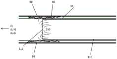
现在参考图1A至图1D,这些图是示出根据本公开的一些实施方案的用于引线去除的系统的示意性系统图。如图1A和图1B中所示,心脏引线30已植入到患者80体内。引线30穿过静脉82并在其远侧端部31处终止于电极32中,所述电极32附接到患者80的心脏84的。引线30在其近侧端部处具有允许进入引线30的内部34的开口36。出于引线去除的目的,假设引线30从其源装置(诸如未示出的起搏装置)断开。Reference is now made to FIGS. 1A-1D , which are schematic system diagrams illustrating systems for lead removal according to some embodiments of the present disclosure. As shown in FIGS. 1A and 1B ,
用于引线去除的系统100包括引线去除管心针(LRS)110,所述LRS 110是适于经由开口36配合到引线内部34中的管心针。LRS 110的长度优选介于50-100cm之间。LRS 110包含生物相容性材料,包括但不限于塑料、钢、钛或镍钛诺。
系统100还包括控制器120。LRS 110在其近侧端部114处附接到控制器120。控制器120是计算装置,并且优选包括控制器用户接口122,所述控制器用户接口122包括如本领域中已知的接口部件,诸如但不限于屏幕、键盘、鼠标或供操作者(未示出)(诸如医疗专业人员)用来控制LRS 110并接收关于其活动或状态的信息的其他部件。The
控制器120还包括振动发生器124,所述振动发生器124生成由附接到振动发生器124的LRS 110使用的振动。替代地,如图1B中所示,LRS 110包括振动发生器118,所述振动发生器118可由控制器120供电和控制。任选地,系统100包括发生器124和118两者。发生器124和/或118能够生成一系列振动频率、振幅和方向。发生器124和118基于本领域中已知的振动生成机制,包括电磁感应振动或基于压电换能器的振动。在图1M中示出振动发生器124或118的非限制性实例,其中振动发生器124或118包括附接到电动机127的圆盘126。振动绳129在附接点128处附接到圆盘126。当电动机127使圆盘126在“A”方向上旋转时,在方向“B”上交替地推动和拉动振动绳129。振动绳129附接到LRS 110,并且机械运动“B”转化成LRS110的机械振动。任选地,振动绳129是刚性的。任选地,振动绳129在单个平面中是刚性的。The controller 120 also includes a
图1C至图1N示出由LRS 110用来将LRS 110锁定到引线30的内侧壁39上的锁定机构113的替代实施方案。示出的实施方案不应被认为是限制性的,并且有可能可使用任何合适的锁定机构。锁定机构113优选是不透射线的。锁定机构113适于在LRS 110锁定到引线30时将LRS 110的振动传递到引线30,如以下进一步描述的。锁定机构113在处于“未锁定”模式时优选具有与LRS 110的外壁116相同或比其更小的直径,从而允许LRS 110穿过引线30。锁定机构113在处于“锁定”模式时优选具有比LRS 110的外壁116更大的直径,从而将锁定机构113压靠在引线30的内侧壁39上以将LRS 110锁定到引线30。然后可将锁定机构113解除锁定,使得LRS 110可从引线30去除或移动到引线30中的另一个位置。FIGS. 1C-1N illustrate an alternative embodiment of the
在图1C和图1D的实施方案中,LRS 110锁定机构113包括由挠性材料形成的线缆锁定头144。锁定头144固定地附接到从锁定头144沿着线缆腔体143延伸的锁定线缆142。锁定线缆142在LRS 110的近侧部退出LRS 110,并且可任选地由执业医师操纵以将LRS 110锁定到引线30或与引线30解除锁定,或者替代地可由控制器120操纵以将LRS 110锁定到引线30或与引线30解除锁定。图1C示出处于未锁定位置的锁定机构113,并且图1D示出当锁定线缆142被拉动时处于锁定位置的锁定机构。当锁定线缆142被释放时,锁定头144弹回到其原始位置以从内壁39解除锁定。In the embodiment of Figures 1C and ID, the
在图1E和图1F的实施方案中,LRS 110锁定结构113包括由可充气材料形成的球囊锁定头148。经由充气腔体149对锁定头148进行充气。充气腔体149在LRS 110的近侧部连接到充气装置(未示出),并且可任选地由执业医师操纵以将LRS 110锁定到引线30或与引线30解除锁定,或者替代地可由控制器120操纵以将LRS 110锁定到引线30或与引线30解除锁定。图1E示出处于未锁定位置的锁定机构113,并且图1F示出当球囊148由泵送到充气腔体149中的压缩气体进行充气时处于锁定位置的锁定机构。当允许气体从球囊148逸出时,球囊148放气以从内壁39解除锁定。In the embodiment of Figures IE and IF, the
在图1G至1J的实施方案中,LRS 110锁定机构113包括由在受热时变形的材料(诸如但不限于镍钛诺)形成的受热变换锁146。变换锁146固定地附接到从变换锁头146延伸并在LRS的近侧部退出LRS的加热丝145。对加热丝进行加热,从而对变换锁146进行加热并改变锁146的形状来将其压靠在引线30的内壁39上,以将LRS 110锁定在所选择的位置处。加热丝145在其近侧端部处连接到加热机构(未示出),所述加热机构可任选地由执业医师操纵以将LRS 110锁定到引线30或与引线30解除锁定,或者替代地可由控制器120操纵以将LRS 110锁定到引线30或与引线30解除锁定。当热量被去除时,锁146恢复到其原始形状以从内壁39解除锁定。图1G和图1I示出处于未锁定位置的锁定机构113,并且图1H和图1J示出处于锁定位置的锁定机构。图1G和图1H示出在受热时弯曲的变换锁146,并且图1I和图1J示出是立方体形并且在受热时膨胀的变换锁146。In the embodiment of Figures 1G-1J, the
在图1K至图1L的实施方案中,LRS 110锁定机构113包括楔形件147和榫钉141。为了将头113锁定到引线30,将榫钉141拉动到楔形件147上,或者替代地诸如通过使LRS 110旋转来将楔形件147驱动到榫钉141中。当楔形件147被驱动到榫钉141中时,使榫钉141张开(图1L)以便压靠在引线30的内壁39上以将LRS 110锁定在所选择的位置处。楔形件147可任选地由执业医师操纵以将LRS 110锁定到引线30或与引线30解除锁定,或者替代地可由控制器120操纵以将LRS 110锁定到引线30或与引线30解除锁定。图1K示出处于未锁定模式的榫钉141。In the embodiment of FIGS. 1K-1L , the
任选地,LRS 110是一次性的,使得每个患者只能使用它一次。对于一次性的LRS110,LRS 110使用一次性使用的连接器(未示出)经由接口114连接到控制器120。一次性使用的连接器包括用于将LRS 110附接到控制器120一次的机构,使得连接器在从控制器120去除之后损坏,从而防止重复使用。Optionally, the
在使用中,通过开口36将LRS 110插入到引线内部34中,并且然后使用LRS 110来将引线从结合组织脱离,如以下将描述的。In use, the
现在参考图2A和图2B至图2H,这些图分别是示出根据本公开的至少一些实施方案的引线去除管心针的使用方法的流程图和说明图。在如图2B中所示的过程200的步骤202中,将LRS 110插入到引线30的内部中。步骤202-212优选是自动化的,并且由控制器120执行或替代地由控制器120与人类操作者一起执行。Reference is now made to FIGS. 2A and 2B-2H, which are flowcharts and illustrations, respectively, illustrating a method of use of a lead removal stylet in accordance with at least some embodiments of the present disclosure. In
在步骤204中并且如在图2B中,使LRS 110移动到在引线30内侧的起始位置,并且如在图2C中,通过使锁定机构113膨胀来将LRS 110锁靠在引线30的内壁39上。这个位置在本文中称为锁定位置。第一锁定位置优选是LRS 110的远侧端部112邻近电极32的位置,如在步骤205中并且如以下进一步描述的。In
现在必须确定引线30是否由结合组织88保持在原处。因此,在步骤206中并且如图2C中所示,由控制器120在LRS中激活或向LRS施加低振幅测试振动150,并且在步骤208中,由控制器120测量对振动的阻力。根据测量的阻力,确定引线30在锁定位置处是否由结合组织88保持在原处。测试振动150的方向是水平的、旋转的或竖直的,或在任何或所有平面中的这些振动的组合。振动150的方向、振幅、周期和频率(共同称为振动类型)优选基于对一系列患者使用所述系统的经验来预先确定。来自LRS 110的振动150在锁定位置处被机械传递到引线30,并且因此引线30也基于所选择的振动类型来振动,但取决于结合组织88的存在,振动的程度有所不同。It must now be determined whether
对振动的低阻力指示引线30在锁定位置处未粘在结合组织88中。因此,在步骤212中并且如在图2D中,将LRS 110解除锁定,并且LRS 110的插入继续进行,直到下一个锁定位置。The low resistance to vibration indicates that the
组合结合通常发生在引线30将金属表面暴露于组织的位置处。在显示引线30的x射线上可见的这些区域中,锁定位置可相隔2-10mm。在引线30的其他部分中,锁定位置可相隔10mm或更多。一旦LRS 110锁定到下一个位置,就重复如在步骤206和208中的用于检查阻力的过程(图2C、图2E、图2G)。Combinatorial bonding typically occurs where
在步骤206和208中对振动的高阻力指示引线30粘在结合组织88中。图2E示出引线30由结合组织88保持在原处的锁定位置。因此,如果阻力较高,则用高振幅组织破坏振动160使LRS 110振动,如在步骤209处并且如图2F中所示。如以上所述,振动可来自内部发生器118或控制器发生器124,如在图1A和图1B中。组织破坏振动160的方向是水平的或竖直的,或这些的组合。振动160方向、振幅、周期和频率(共同称为振动类型)根据测量的阻力水平进行修改。振动160的类型优选基于对一系列患者使用所述系统的经验来预先确定。来自LRS 110的振动160在锁定位置处被机械传递到引线30,并且因此引线30也基于所选择的振动类型来振动。振动160理想地破坏结合组织88,诸如在图2G中。High resistance to vibration in
在组织破坏振动160的周期完成之后,重复步骤206和208以确定是否仍存在对来自LRS 110的测试振动150的高阻力,以便评估结合组织88是否已破坏。如果阻力保持为高,则重复步骤209并且在锁定位置处再次施加高振幅组织破坏振动160。随后施加的组织破坏振动160通常具有更大的类型,其中周期、频率或振幅中的一者或多者有所增加并且还任选地具有不同的振动方向。After the cycle of
在振动周期后,在锁定位置处再次测试LRS 110的阻力,如在步骤206和208中。一旦已确定阻力减小,就假设结合组织88已破坏并且引线30现在从结合组织88断开。因此,在步骤212中并且如图2H中所示,现在将LRS 110解除锁定并且使其移动到下一个锁定位置。After the vibration period, the resistance of the
LRS 110的起始位置优选是在LRS 110的远侧端部112处的锁定机构113定位在电极32所在的引线远侧端部31处的位置,诸如在步骤205中。在这种情况下,已知必须将电极32从其在心脏84的壁中的附接点去除。因此,将LRS 110锁定在电极32的位置处,并且如在步骤209中,使LRS 110振动。如上所述,振动类型160由控制器120或控制器120的操作者调整。LRS 110的组织破坏振动160在锁定电极点处导致传递到引线30的振动。这种振动理想地导致电极32从附接组织(在这种情况下为心脏84的壁)脱离。The starting position of the
为了确认电极32是否确实已松开,测量在电极锁定点处的LRS110的阻力,如在步骤206和208中。高阻力指示电极32仍附接,并且重复步骤209并在锁定位置处再次施加组织破坏振动160。随后施加的组织破坏振动160通常具有更大的类型,其中周期、频率或振幅中的一者或多者有所增加并且还任选地具有不同的振动方向。在振动周期后,在锁定位置处再次测试LRS 110的阻力,如在步骤206和208中。一旦已确定阻力减小,就假设电极32已除去。因此,在步骤212中,将LRS 110解除锁定并使其移动到下一个锁定位置。To confirm that the
在步骤206和208的阻力测量并确定阻力较低后,在步骤210中控制器120或操作者评估是否已到达最终锁定位置。如果是这种情况,则在步骤214中通过将引线30从患者80体内拉出来去除引线30。After the resistance measurements at
从以上应当理解,LRS 110在从引线30的近侧开口36开始并一直前进到引线30的远侧端部31的方向上从锁定位置移动到锁定位置。替代地和优选地,LRS 110的第一锁定位置是引线30的远侧端部31(以释放电极32),之后是逐渐更靠近引线30的近侧开口36的锁定位置。替代地,LRS 110的第一锁定位置是引线30的远侧端部31(以释放电极32),之后是LRS110在从引线30的近侧开口36开始并一直前进到引线30的远侧端部31的方向上从锁定位置移动到锁定位置。It should be understood from the above that the
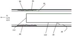
现在参考图3A至图3C,这些图是示出根据本公开的一些实施方案的用于引线去除的系统的示意性系统图。如图3A中所示,心脏引线30已植入到患者80体内。图3A至图3C的实施方案与图1A中所示的实施方案相同,包括具有相同编号的部件。Reference is now made to FIGS. 3A-3C , which are schematic system diagrams illustrating systems for lead removal according to some embodiments of the present disclosure. As shown in FIG. 3A ,
在图3A至图3C的实施方案中,LRS 310包括沿着要插入到引线30中的LRS 310的全长延伸的锁定机构313。在图3B至图3C的示例性实施方案中,锁定机构313包括由可充气材料形成的沿着LRS310的外表面定位的多个球囊370。经由充气腔体372对球囊370进行充气。充气腔体372在LRS 310的近侧部连接到充气装置(未示出),并且可任选地由执业医师操纵以将LRS 310锁定到引线30或与引线30解除锁定,或者替代地可由控制器120操纵以将LRS310锁定到引线30或与引线30解除锁定。图3B示出处于未锁定位置(放气)的锁定机构313,并且图3C示出当球囊370由泵送到充气腔体372中的压缩气体进行充气以将LRS 310沿着LRS 310的插入的全长锁定到引线30的内壁39时处于锁定位置的锁定机构。当允许气体从球囊370逸出时,球囊372放气以从引线30的内壁39解除锁定。尽管图3B至图3C的锁定机构313使用球囊锁定机构,但是应当理解,任何类型的锁定机构,包括但不限于在图1C至图1L中描述的锁定机构的全长变型是可能的,实现为具有多个锁定点,并且图1M至图1N的具体实施方案不应被认为是限制性的。In the embodiment of FIGS. 3A-3C , the
现在参考图4A和图4B至图4E,这些图分别是示出根据本公开的至少一些实施方案的引线去除管心针的使用方法的流程图和说明图。在如图4B中所示的过程400的步骤402中,将LRS 310插入到引线30的内部中。步骤402、405、406、408和409优选是自动化的,并且由控制器140执行或替代地由控制器140与人类操作者一起执行。Reference is now made to FIGS. 4A and 4B-4E, which are flowcharts and illustrations, respectively, illustrating a method of use of a lead removal stylet in accordance with at least some embodiments of the present disclosure. In
在步骤405中并且如在图4B中,使LRS 310移动到在引线30内侧的起始位置,并且如在图4C中,通过使锁定机构313膨胀来将LRS 310锁靠在引线30的内壁39的多个点上。这些位置在本文中称为锁定位置。起始锁定位置优选处于LRS 310一直推入到引线30中,使得远侧端部312邻近电极32的状态。In
在步骤409中,用高振幅组织破坏460使LRS 310振动并且如图4D中所示。振动从控制器发生器124生成,如在图3A中。组织破坏振动460的方向是水平的或竖直的,或这些方向的组合。振动460的方向、振幅、周期和频率(共同称为振动类型)优选基于对一系列患者使用所述系统的经验来预先确定。来自LRS 310的振动460在多个锁定位置处被机械传递到引线30,在所述多个锁定位置处,球囊370或其他替代的锁定机构313锁靠在内壁39上,并且因此引线30也基于所选择的振动类型来振动。振动460理想地破坏固定住引线30的结合组织。In
现在必须确定引线30是否仍由结合组织保持在原处。因此,在步骤406中并如图4E中所示,由控制器140在LRS 310中激活或向LRS 310施加低振幅测试振动450,并且在步骤408中,由控制器140测量对振动的阻力。根据测量的阻力,确定引线30是否仍由结合组织保持在原处。测试振动450的方向是水平的、旋转的或竖直的,或在任何或所有平面中的这些振动的组合。振动450的方向、振幅、周期和频率(共同称为振动类型)优选基于对一系列患者使用所述系统的经验来预先确定。来自LRS 310的振动450在多个锁定位置处被机械传递到引线30,在所述多个锁定位置处,球囊370或其他替代的锁定机构313锁靠在内壁39上,并且因此引线30也基于所选择的振动类型来振动,但取决于结合组织的存在,振动的程度有所不同。It must now be determined whether the
在步骤406和408中对振动的高阻力指示引线30粘在结合组织中。在这种情况下,重复步骤409,并且然后重复步骤406和408,直到检测到对振动的低阻力。随后再施加的组织破坏振动460任选地具有更大的类型,其中周期、频率或振幅中的一者或多者有所增加并且还任选地具有不同的振动方向。任选地,当在步骤406和408中检测到对振动450的高阻力时,将LRS 310解除锁定、在引线30内向前或向后移位、锁定在原处,并且然后重复步骤409。High resistance to vibration in
对振动450的低阻力指示引线30未粘在结合组织中。一旦已确定阻力减小,就假设结合组织已破坏并且引线30现在从结合组织断开。因此,在步骤414中,现在将LRS 310解除锁定,并且通过将引线30从患者80体内拉出来去除引线30。Low resistance to
应理解,为了清楚起见在分开的实施方案的上下文中描述的目前所公开的主题的某些特征也可在单个实施方案中以组合的方式提供。相反,为了简洁起见在单个实施方案的上下文中描述的目前所公开的主题的各种特征也可分开地或以任何适合的子组合的方式提供。It is understood that certain features of the presently disclosed subject matter that are, for clarity, described in the context of separate implementations, may also be provided in combination in a single implementation. Conversely, various features of the presently disclosed subject matter that are, for brevity, described in the context of a single embodiment, may also be provided separately or in any suitable subcombination.
应当理解,本公开在其应用中不限于在本文所含有的描述中陈述的或在附图中示出的细节。本公开能够具有其他实施方案并且能够以各种方式实践或实施。本领域技术人员将容易理解,在不脱离在所附权利要求中限定并且由所附权利要求限定的本公开的范围的情况下,可对如以上所述的本公开的实施方案进行各种修改和改变。It is to be understood that the disclosure is not limited in its application to the details set forth in the description contained herein or illustrated in the accompanying drawings. The present disclosure is capable of other embodiments and of being practiced or carried out in various ways. Those skilled in the art will readily appreciate that various modifications may be made to the embodiments of the present disclosure as described above without departing from the scope of the disclosure as defined in and by the appended claims and change.
Claims (30)
Applications Claiming Priority (3)
| Application Number | Priority Date | Filing Date | Title |
|---|---|---|---|
| US201762594034P | 2017-12-04 | 2017-12-04 | |
| US62/594,034 | 2017-12-04 | ||
| PCT/IL2018/051332WO2019111255A1 (en) | 2017-12-04 | 2018-12-04 | System and method for lead extraction |
Publications (2)
| Publication Number | Publication Date |
|---|---|
| CN111526824Atrue CN111526824A (en) | 2020-08-11 |
| CN111526824B CN111526824B (en) | 2023-10-31 |
Family
ID=66751406
Family Applications (1)
| Application Number | Title | Priority Date | Filing Date |
|---|---|---|---|
| CN201880080246.0AActiveCN111526824B (en) | 2017-12-04 | 2018-12-04 | Systems and methods for lead extraction |
Country Status (4)
| Country | Link |
|---|---|
| US (1) | US11771448B2 (en) |
| EP (1) | EP3720373A4 (en) |
| CN (1) | CN111526824B (en) |
| WO (1) | WO2019111255A1 (en) |
Families Citing this family (5)
| Publication number | Priority date | Publication date | Assignee | Title |
|---|---|---|---|---|
| US9889294B2 (en)* | 2013-08-25 | 2018-02-13 | Talpanetics bv | Extractor for removing a lead from a patient |
| IL274764B2 (en)* | 2020-05-19 | 2024-08-01 | Xtrac O S Ltd | Vibration system and device for extracting a lead of an electronic cardiac implant |
| WO2022171419A1 (en)* | 2021-02-12 | 2022-08-18 | Koninklijke Philips N.V. | Systems and apparatuses of an electromechanical unlockable lead locking device |
| IL283558B2 (en)* | 2021-05-30 | 2023-03-01 | Xtrac O S Ltd | Coil blocking device |
| WO2023088808A1 (en)* | 2021-11-22 | 2023-05-25 | Koninklijke Philips N.V. | Apparatus with stylet for kink navigation or the like in a catheter lead lumen |
Citations (9)
| Publication number | Priority date | Publication date | Assignee | Title |
|---|---|---|---|---|
| US4582056A (en)* | 1983-03-30 | 1986-04-15 | Mccorkle Jr Charles E | Endocardial lead extraction apparatus and method |
| US6183469B1 (en)* | 1997-08-27 | 2001-02-06 | Arthrocare Corporation | Electrosurgical systems and methods for the removal of pacemaker leads |
| US6241692B1 (en)* | 1998-10-06 | 2001-06-05 | Irvine Biomedical, Inc. | Ultrasonic ablation device and methods for lead extraction |
| US20030036788A1 (en)* | 2000-12-04 | 2003-02-20 | The Spectranetics Corporation | Lead locking device and method |
| US20090234367A1 (en)* | 2008-02-25 | 2009-09-17 | Sumit Verma | Force assessment device and method for lead extraction |
| US20130116704A1 (en)* | 2011-11-03 | 2013-05-09 | Vascomed Gmbh | Device for Explanting Electrode Leads |
| CN103635228A (en)* | 2011-04-01 | 2014-03-12 | 立泰心脏有限公司 | Lead wire extraction method and device thereof |
| WO2017029548A1 (en)* | 2015-08-17 | 2017-02-23 | Talpanetics bv | Extractor for removing a lead from a patient |
| US20170333016A1 (en)* | 2016-05-20 | 2017-11-23 | Cook Medical Technologies Llc | Vibrating medical device assembly and method of retrieving embedded implantable device |
Family Cites Families (3)
| Publication number | Priority date | Publication date | Assignee | Title |
|---|---|---|---|---|
| RU2360614C1 (en)* | 2007-10-09 | 2009-07-10 | Владимир Сергеевич Изранцев | Way of removal of endocardial electrodes by means of energy of ultrasound |
| EP2602001A1 (en) | 2011-12-08 | 2013-06-12 | BIOTRONIK SE & Co. KG | Medical implant and medical arrangement |
| US10207105B2 (en)* | 2013-08-25 | 2019-02-19 | Talpanetics bv | Extractor for removing a lead from a patient |
- 2018
- 2018-12-04EPEP18885167.9Apatent/EP3720373A4/enactivePending
- 2018-12-04USUS16/769,245patent/US11771448B2/enactiveActive
- 2018-12-04WOPCT/IL2018/051332patent/WO2019111255A1/ennot_activeCeased
- 2018-12-04CNCN201880080246.0Apatent/CN111526824B/enactiveActive
Patent Citations (9)
| Publication number | Priority date | Publication date | Assignee | Title |
|---|---|---|---|---|
| US4582056A (en)* | 1983-03-30 | 1986-04-15 | Mccorkle Jr Charles E | Endocardial lead extraction apparatus and method |
| US6183469B1 (en)* | 1997-08-27 | 2001-02-06 | Arthrocare Corporation | Electrosurgical systems and methods for the removal of pacemaker leads |
| US6241692B1 (en)* | 1998-10-06 | 2001-06-05 | Irvine Biomedical, Inc. | Ultrasonic ablation device and methods for lead extraction |
| US20030036788A1 (en)* | 2000-12-04 | 2003-02-20 | The Spectranetics Corporation | Lead locking device and method |
| US20090234367A1 (en)* | 2008-02-25 | 2009-09-17 | Sumit Verma | Force assessment device and method for lead extraction |
| CN103635228A (en)* | 2011-04-01 | 2014-03-12 | 立泰心脏有限公司 | Lead wire extraction method and device thereof |
| US20130116704A1 (en)* | 2011-11-03 | 2013-05-09 | Vascomed Gmbh | Device for Explanting Electrode Leads |
| WO2017029548A1 (en)* | 2015-08-17 | 2017-02-23 | Talpanetics bv | Extractor for removing a lead from a patient |
| US20170333016A1 (en)* | 2016-05-20 | 2017-11-23 | Cook Medical Technologies Llc | Vibrating medical device assembly and method of retrieving embedded implantable device |
Also Published As
| Publication number | Publication date |
|---|---|
| US11771448B2 (en) | 2023-10-03 |
| EP3720373A4 (en) | 2021-09-01 |
| EP3720373A1 (en) | 2020-10-14 |
| WO2019111255A1 (en) | 2019-06-13 |
| CN111526824B (en) | 2023-10-31 |
| US20210186539A1 (en) | 2021-06-24 |
Similar Documents
| Publication | Publication Date | Title |
|---|---|---|
| CN111526824B (en) | Systems and methods for lead extraction | |
| JP6522657B2 (en) | Patient Access Device with Gas Removal Function | |
| US10993735B2 (en) | Method and catheter for creating an interatrial aperture | |
| EP1933756B1 (en) | Steerable lesion excluding heart implants for congestive heart failure | |
| JP5869803B2 (en) | Minimally invasive intervention robot | |
| JP7237953B2 (en) | pericardial grasper | |
| US20100331854A1 (en) | Device and method for performing treatment in a pericardial space | |
| CN111936061A (en) | Medical Equipment and Disposal Methods | |
| JP2010540022A (en) | Implantable ultrasound system for maintaining vascular patency | |
| CN110430918A (en) | Modular Implant Delivery and Positioning System | |
| US12004707B2 (en) | Airway visualization system | |
| WO2007050941A1 (en) | System, apparatus, and method for imaging and treating tissue | |
| EP2731509A1 (en) | Body part repositioning apparatus and method | |
| CN115279269A (en) | cardiac pacing device | |
| CN112566569B (en) | Pressure sensing implantation tool | |
| JP4383119B2 (en) | Ultrasonic therapy device | |
| US20230190315A1 (en) | Vibration system and device for extraction of a lead of a cardiac implantable electronic device | |
| US9326793B2 (en) | Needle for physically separating and penetrating the pericardium | |
| Hijazi et al. | Complications during percutaneous interventions for congenital and structural heart disease | |
| JP2021098020A (en) | Lasso catheter with balloon | |
| JP2020182846A (en) | Use of pulmonary vein isolation for patients with atrial fibrillation | |
| EP4518937A1 (en) | Enhanced catheters and methods of use | |
| EP4618862A1 (en) | Intravascular lithoplasty balloon systems and devices with sterile, disposable single-piece and unitary cable, handle, hub, catheter and balloon | |
| Mullins | Set-up and Equipment for a Pediatric/Congenital Interventional Cardiac Catheterization Laboratory |
Legal Events
| Date | Code | Title | Description |
|---|---|---|---|
| PB01 | Publication | ||
| PB01 | Publication | ||
| SE01 | Entry into force of request for substantive examination | ||
| SE01 | Entry into force of request for substantive examination | ||
| TA01 | Transfer of patent application right | Effective date of registration:20210531 Address after:Israel Netanya Applicant after:Exlink Ltd. Address before:Jerusalem, Israel Applicant before:U. Stein | |
| TA01 | Transfer of patent application right | ||
| GR01 | Patent grant | ||
| GR01 | Patent grant |