CN111525621A - Distributed coordination control method and system for DC power distribution system of building group - Google Patents
Distributed coordination control method and system for DC power distribution system of building groupDownload PDFInfo
- Publication number
- CN111525621A CN111525621ACN202010432113.4ACN202010432113ACN111525621ACN 111525621 ACN111525621 ACN 111525621ACN 202010432113 ACN202010432113 ACN 202010432113ACN 111525621 ACN111525621 ACN 111525621A
- Authority
- CN
- China
- Prior art keywords
- unit
- power
- grid
- control
- distribution system
- Prior art date
- Legal status (The legal status is an assumption and is not a legal conclusion. Google has not performed a legal analysis and makes no representation as to the accuracy of the status listed.)
- Granted
Links
Images


Classifications
- H—ELECTRICITY
- H02—GENERATION; CONVERSION OR DISTRIBUTION OF ELECTRIC POWER
- H02J—CIRCUIT ARRANGEMENTS OR SYSTEMS FOR SUPPLYING OR DISTRIBUTING ELECTRIC POWER; SYSTEMS FOR STORING ELECTRIC ENERGY
- H02J3/00—Circuit arrangements for AC mains or AC distribution networks
- H02J3/38—Arrangements for parallely feeding a single network by two or more generators, converters or transformers
- H02J3/381—Dispersed generators
- H—ELECTRICITY
- H02—GENERATION; CONVERSION OR DISTRIBUTION OF ELECTRIC POWER
- H02J—CIRCUIT ARRANGEMENTS OR SYSTEMS FOR SUPPLYING OR DISTRIBUTING ELECTRIC POWER; SYSTEMS FOR STORING ELECTRIC ENERGY
- H02J3/00—Circuit arrangements for AC mains or AC distribution networks
- H02J3/008—Circuit arrangements for AC mains or AC distribution networks involving trading of energy or energy transmission rights
- H—ELECTRICITY
- H02—GENERATION; CONVERSION OR DISTRIBUTION OF ELECTRIC POWER
- H02J—CIRCUIT ARRANGEMENTS OR SYSTEMS FOR SUPPLYING OR DISTRIBUTING ELECTRIC POWER; SYSTEMS FOR STORING ELECTRIC ENERGY
- H02J3/00—Circuit arrangements for AC mains or AC distribution networks
- H02J3/12—Circuit arrangements for AC mains or AC distribution networks for adjusting voltage in AC networks by changing a characteristic of the network load
- H02J3/14—Circuit arrangements for AC mains or AC distribution networks for adjusting voltage in AC networks by changing a characteristic of the network load by switching loads on to, or off from, network, e.g. progressively balanced loading
- H—ELECTRICITY
- H02—GENERATION; CONVERSION OR DISTRIBUTION OF ELECTRIC POWER
- H02J—CIRCUIT ARRANGEMENTS OR SYSTEMS FOR SUPPLYING OR DISTRIBUTING ELECTRIC POWER; SYSTEMS FOR STORING ELECTRIC ENERGY
- H02J3/00—Circuit arrangements for AC mains or AC distribution networks
- H02J3/28—Arrangements for balancing of the load in a network by storage of energy
- H02J3/32—Arrangements for balancing of the load in a network by storage of energy using batteries with converting means
- H—ELECTRICITY
- H02—GENERATION; CONVERSION OR DISTRIBUTION OF ELECTRIC POWER
- H02J—CIRCUIT ARRANGEMENTS OR SYSTEMS FOR SUPPLYING OR DISTRIBUTING ELECTRIC POWER; SYSTEMS FOR STORING ELECTRIC ENERGY
- H02J3/00—Circuit arrangements for AC mains or AC distribution networks
- H02J3/38—Arrangements for parallely feeding a single network by two or more generators, converters or transformers
- H02J3/388—Islanding, i.e. disconnection of local power supply from the network
- H—ELECTRICITY
- H02—GENERATION; CONVERSION OR DISTRIBUTION OF ELECTRIC POWER
- H02J—CIRCUIT ARRANGEMENTS OR SYSTEMS FOR SUPPLYING OR DISTRIBUTING ELECTRIC POWER; SYSTEMS FOR STORING ELECTRIC ENERGY
- H02J2300/00—Systems for supplying or distributing electric power characterised by decentralized, dispersed, or local generation
- H02J2300/20—The dispersed energy generation being of renewable origin
- H02J2300/22—The renewable source being solar energy
- H02J2300/24—The renewable source being solar energy of photovoltaic origin
- H02J2300/26—The renewable source being solar energy of photovoltaic origin involving maximum power point tracking control for photovoltaic sources
- Y—GENERAL TAGGING OF NEW TECHNOLOGICAL DEVELOPMENTS; GENERAL TAGGING OF CROSS-SECTIONAL TECHNOLOGIES SPANNING OVER SEVERAL SECTIONS OF THE IPC; TECHNICAL SUBJECTS COVERED BY FORMER USPC CROSS-REFERENCE ART COLLECTIONS [XRACs] AND DIGESTS
- Y02—TECHNOLOGIES OR APPLICATIONS FOR MITIGATION OR ADAPTATION AGAINST CLIMATE CHANGE
- Y02B—CLIMATE CHANGE MITIGATION TECHNOLOGIES RELATED TO BUILDINGS, e.g. HOUSING, HOUSE APPLIANCES OR RELATED END-USER APPLICATIONS
- Y02B70/00—Technologies for an efficient end-user side electric power management and consumption
- Y02B70/30—Systems integrating technologies related to power network operation and communication or information technologies for improving the carbon footprint of the management of residential or tertiary loads, i.e. smart grids as climate change mitigation technology in the buildings sector, including also the last stages of power distribution and the control, monitoring or operating management systems at local level
- Y02B70/3225—Demand response systems, e.g. load shedding, peak shaving
- Y—GENERAL TAGGING OF NEW TECHNOLOGICAL DEVELOPMENTS; GENERAL TAGGING OF CROSS-SECTIONAL TECHNOLOGIES SPANNING OVER SEVERAL SECTIONS OF THE IPC; TECHNICAL SUBJECTS COVERED BY FORMER USPC CROSS-REFERENCE ART COLLECTIONS [XRACs] AND DIGESTS
- Y02—TECHNOLOGIES OR APPLICATIONS FOR MITIGATION OR ADAPTATION AGAINST CLIMATE CHANGE
- Y02E—REDUCTION OF GREENHOUSE GAS [GHG] EMISSIONS, RELATED TO ENERGY GENERATION, TRANSMISSION OR DISTRIBUTION
- Y02E10/00—Energy generation through renewable energy sources
- Y02E10/50—Photovoltaic [PV] energy
- Y02E10/56—Power conversion systems, e.g. maximum power point trackers
- Y—GENERAL TAGGING OF NEW TECHNOLOGICAL DEVELOPMENTS; GENERAL TAGGING OF CROSS-SECTIONAL TECHNOLOGIES SPANNING OVER SEVERAL SECTIONS OF THE IPC; TECHNICAL SUBJECTS COVERED BY FORMER USPC CROSS-REFERENCE ART COLLECTIONS [XRACs] AND DIGESTS
- Y04—INFORMATION OR COMMUNICATION TECHNOLOGIES HAVING AN IMPACT ON OTHER TECHNOLOGY AREAS
- Y04S—SYSTEMS INTEGRATING TECHNOLOGIES RELATED TO POWER NETWORK OPERATION, COMMUNICATION OR INFORMATION TECHNOLOGIES FOR IMPROVING THE ELECTRICAL POWER GENERATION, TRANSMISSION, DISTRIBUTION, MANAGEMENT OR USAGE, i.e. SMART GRIDS
- Y04S20/00—Management or operation of end-user stationary applications or the last stages of power distribution; Controlling, monitoring or operating thereof
- Y04S20/20—End-user application control systems
- Y04S20/222—Demand response systems, e.g. load shedding, peak shaving
Landscapes
- Engineering & Computer Science (AREA)
- Power Engineering (AREA)
- Supply And Distribution Of Alternating Current (AREA)
Abstract
Description
Translated fromChinese技术领域technical field
本发明涉及配电网技术领域,特别涉及一种楼宇群直流配电系统的集散协调控制方法及系统。The invention relates to the technical field of power distribution networks, in particular to a method and a system for collecting and distributing coordinated control of a direct current power distribution system of a building group.
背景技术Background technique
近年来,随着电能变换技术以及网络通信系统的发展与进步,民用住宅及公共建筑等典型楼宇群中直流负荷的占比大幅上升,加之电力电子装置的广泛应用以及分布式可再生能源的接入,现有的交流配电系统已难以满足新的发展需求。而直流供电方式的引入从设备生产制造和系统运行两个方面提高了楼宇群配电网的性能,不仅为用户提供了高电能质量的用电环境,而且能够满足楼宇中计算机、通信设备等敏感负荷对配电网高可靠、低损耗的特殊要求,更有利于如电动汽车、智能家电等柔性负荷的安全高效运行。In recent years, with the development and progress of power conversion technology and network communication systems, the proportion of DC loads in typical building groups such as residential and public buildings has increased significantly. In addition, the wide application of power electronic devices and the connection of distributed renewable energy Into, the existing AC power distribution system has been difficult to meet the new development needs. The introduction of DC power supply has improved the performance of the building group distribution network from the two aspects of equipment manufacturing and system operation. The special requirements of the load on the distribution network with high reliability and low loss are more conducive to the safe and efficient operation of flexible loads such as electric vehicles and smart home appliances.
楼宇群直流配电系统作为新兴研究方向,主要成果局限于楼宇群直流配电系统组成、结构与稳定性控制方面,且缺乏统一的标准与参考。其中关于控制方法的研究主要成果,从形式上包括集中控制与分散控制两个类别,从目标上包括实现楼宇群直流配电系统稳定性运行和故障监测与保护控制两个角度。集中控制以配电系统通信网络为基础,将楼宇群直流配电系统各组成单元状态信息汇总至集中控制器进行统一运算,并输出各控制变量至相应变流器实现系统稳定与优化运行等目标。分散控制方法以基于直流母线电压信号的分散控制为代表,以直流母线电压为基础确定各模块的工作模式,无需通信且控制器设计简单。稳定性控制实现配电网系统各组成单元功率状态处于运行极限之间时,直流母线电压维持在正常范围。故障控制实现直流母线电压失控后楼宇群配电系统内主要单元的保护,以及故障清除后正常运行状态的恢复。As an emerging research direction of DC power distribution system for buildings, the main achievements are limited to the composition, structure and stability control of DC power distribution systems for buildings, and there is a lack of unified standards and references. Among them, the main results of the research on control methods include two categories of centralized control and decentralized control in form, and two aspects including the realization of stable operation and fault monitoring and protection control of DC power distribution system of building groups in terms of goals. The centralized control is based on the communication network of the power distribution system. The state information of each component of the DC power distribution system of the building group is summarized to the centralized controller for unified calculation, and each control variable is output to the corresponding converter to achieve the goals of system stability and optimized operation. . The decentralized control method is represented by the decentralized control based on the DC bus voltage signal, and the working mode of each module is determined based on the DC bus voltage, no communication is required, and the controller design is simple. The stability control realizes that the DC bus voltage is maintained in the normal range when the power state of each component of the distribution network system is between the operating limits. The fault control realizes the protection of the main units in the power distribution system of the building group after the DC bus voltage is out of control, and the restoration of the normal operation state after the fault is cleared.
在实际应用中,对于楼宇群直流配电系统控制方法,应结合系统各组成单元功率情况及直流母线电压状态等多中状态信息,综合离网、并网状态,正常、故障状态等多种运行状态,实现以系统的稳定运行为首要目标,并在此基础上实现系统的经济最优化运行的控制目标。并且,由于目前楼宇群直流配电系统研究尚无标准与规范,其控制方法设计应兼顾居民、商业、工业应用等多种楼宇群直流配电场景。In practical applications, for the control method of the DC power distribution system of the building group, it is necessary to combine the power status of each component of the system and the DC bus voltage status and other multi-state information, and integrate the off-grid, grid-connected status, normal, fault status and other operations. state, to achieve the stable operation of the system as the primary goal, and on this basis to achieve the control goal of the economic optimal operation of the system. In addition, since there is no standard and specification for the current research on the DC power distribution system of buildings, the control method design should take into account various DC power distribution scenarios of buildings such as residential, commercial, and industrial applications.
目前,虽然有部分文献对楼宇群直流配电系统的组成成分、拓扑结构、控制方法进行了讨论,但未具体分析和说明楼宇群直流配电系统多种运行模态下的控制方法及过程,且缺乏关于楼宇群直流配电系统经济性优化运行的研究成果。At present, although some literatures have discussed the composition, topology, and control methods of the DC power distribution system in buildings, they have not specifically analyzed and explained the control methods and processes under various operating modes of the DC power distribution system in buildings. And there is a lack of research results on the economical optimal operation of DC power distribution systems in buildings.
在公开号为CN102593832B的中国发明授权专利《一种适用于现代楼宇的三线制直流微网系统及其控制方法》中提出了一种适用于现代楼宇的三线制直流微网系统组成与架构,以及正常状态与大电网故障状态的相应控制方法。该方法控制目标明确,控制过程简单,可以实现特定系统结构下的长期稳定运行。但其无法实现系统运行经济性优化和方法通用性。The composition and structure of a three-wire DC microgrid system suitable for modern buildings is proposed in the Chinese invention authorized patent with publication number CN102593832B "A three-wire DC microgrid system suitable for modern buildings and its control method", and Corresponding control methods for normal state and large grid fault state. The method has clear control objectives, simple control process, and can achieve long-term stable operation under a specific system structure. However, it cannot realize the economic optimization of system operation and the generality of the method.
发明内容SUMMARY OF THE INVENTION
本发明的目的在于克服现有技术存在的缺陷,实现楼宇群直流配电系统稳定性与经济性运行的统一,以及多种运行状态与场景的统一。The purpose of the present invention is to overcome the defects existing in the prior art, and realize the unification of the stability and economical operation of the DC power distribution system of a building group, as well as the unification of various operating states and scenarios.
为实现以上目的,本发明采用一种楼宇群直流配电系统的集散协调控制方法,所述楼宇群直流配电系统的各组成单元均与直流母线相连,包括如下步骤:In order to achieve the above purpose, the present invention adopts a distributed coordination control method for a DC power distribution system of a building group, wherein each component unit of the DC power distribution system of a building group is connected to a DC bus, including the following steps:
本地控制器基于直流母线电压所处区间,按照预设规则控制各组成单元对应的单元级控制器的运行模式,其中本地控制器预先构建于各组成单元内部,单元级控制器至少具备恒压控制、恒流控制和恒功率控制三种运行模式;The local controller controls the operation mode of the unit-level controller corresponding to each component unit according to preset rules based on the interval of the DC bus voltage. The local controller is pre-built inside each component unit, and the unit-level controller at least has constant voltage control. , three operating modes of constant current control and constant power control;
集中控制器计算预设优化目标的优化结果,并基于预设优化目标的优化结果,控制相应组成单元的预设优化目标达到该优化结果。The centralized controller calculates the optimization result of the preset optimization objective, and based on the optimization result of the preset optimization objective, controls the preset optimization objective of the corresponding constituent unit to achieve the optimization result.
进一步地,所述直流母线电压所处区间包括5个运行区间:第1运行区间的直流母线电压条件为UL1<Udc<UH1,第2运行区间的直流母线电压条件为UH1<Udc<UH2,第3运行区间的直流母线电压条件为UL2<Udc<UL1,第4运行区间的直流母线电压条件为Udc>UH2,第5运行区间的直流母线电压条件为Udc<UL2;其中,Udc为直流母线电压,UL2、UL1、UH1、UH2分别为电压分层临界值。Further, the interval in which the DC bus voltage is located includes five operating intervals: the DC bus voltage condition in the first operating interval is UL1 <Udc <UH1 , and the DC bus voltage condition in the second operating interval is UH1 <Udc <UH2 , the DC bus voltage condition in the third operation interval is UL2 <Udc <UL1 , the DC bus voltage condition in the fourth operation interval is Udc >UH2 , and the DC bus voltage condition in the fifth operation interval is Udc <UL2 ; wherein, Udc is the DC bus voltage, and UL2 , UL1 , UH1 , and UH2 are the voltage stratification critical values, respectively.
进一步地,在并网运行模式下,所述本地控制器基于直流母线电压所处区间,按照预设规则控制各组成单元对应的单元级控制器的运行模式,包括:Further, in the grid-connected operation mode, the local controller controls the operation mode of the unit-level controller corresponding to each component unit according to preset rules based on the interval where the DC bus voltage is located, including:
当所述直流母线电压处于所述第1运行区间时,将并网单元端口作为松弛节点,采用下垂控制方法控制所述直流母线电压,并控制发电单元处于MPPT运行模式,储能单元处于不工作或充放电恢复阶段;When the DC bus voltage is in the first operating interval, the port of the grid-connected unit is used as a slack node, the droop control method is used to control the DC bus voltage, and the power generation unit is controlled to be in the MPPT operation mode, and the energy storage unit is not working or charge-discharge recovery phase;
当所述直流母线电压处于所述第2运行区间或第3运行区间时,由储能单元采用下垂控制方法控制并网单元端口流通功率与电压变化量满足预设下垂控制关系,并补偿系统偏差功率,使并网单元端口输出恒定极限功率;以及控制发电单元处于MPPT运行模式;When the DC bus voltage is in the second operating interval or the third operating interval, the energy storage unit adopts the droop control method to control the port circulating power and the voltage change of the grid-connected unit to satisfy the preset droop control relationship, and compensate the system deviation power, so that the port of the grid-connected unit outputs a constant limit power; and control the power generation unit to be in the MPPT operation mode;
当所述直流母线电压处于所述第4运行区间时,控制发电单元退出MPPT工作模式,进入恒压运行状态,并向所述单元级控制器输出端口指令参考电压,维持所述直流母线电压;When the DC bus voltage is in the fourth operating interval, control the power generation unit to exit the MPPT working mode and enter a constant voltage operation state, and output a port command reference voltage to the unit-level controller to maintain the DC bus voltage;
当所述直流母线电压处于所述第5运行区间时,控制负荷单元遵循负荷优先级进行减负荷操作,使母线电压恢复正常运行区间。When the DC bus voltage is in the fifth operating interval, the load unit is controlled to perform a load shedding operation according to the load priority, so that the bus voltage returns to the normal operating interval.
进一步地,在离网运行模式下,所述本地控制器基于直流母线电压所处区间,按照预设规则控制各组成单元对应的单元级控制器的运行模式,包括:Further, in the off-grid operation mode, the local controller controls the operation mode of the unit-level controller corresponding to each component unit according to preset rules based on the interval where the DC bus voltage is located, including:
当所述直流母线电压处于所述第1运行区间时,在储能单元容量处于正常状态时,将储能单元端口作为松弛节点,采用下垂控制方法控制所述直流母线电压,并控制发电单元处于MPPT运行模式;否则,将发电单元端口作为松弛节点,维持所述直流母线电压,储能单元处于不工作或充放电恢复阶段;When the DC bus voltage is in the first operating interval, when the capacity of the energy storage unit is in a normal state, the port of the energy storage unit is used as a slack node, the droop control method is used to control the DC bus voltage, and the power generation unit is controlled to be in the normal state. MPPT operation mode; otherwise, the power generation unit port is used as a slack node to maintain the DC bus voltage, and the energy storage unit is in the inactive or charge-discharge recovery stage;
当所述直流母线电压处于所述第2运行区间或第3运行区间时,将储能单元端口作为松弛节点,采用下垂控制方法维持所述直流母线电压,控制发电单元处于MPPT运行模式;When the DC bus voltage is in the second operating interval or the third operating interval, the port of the energy storage unit is used as a slack node, the droop control method is used to maintain the DC bus voltage, and the power generation unit is controlled to be in the MPPT operation mode;
当所述直流母线电压处于所述第4运行区间时,控制发电单元退出MPPT工作模式,进入恒压运行状态,并向所述单元级控制器输出端口指令参考电压,维持所述直流母线电压;When the DC bus voltage is in the fourth operating interval, control the power generation unit to exit the MPPT working mode and enter a constant voltage operation state, and output a port command reference voltage to the unit-level controller to maintain the DC bus voltage;
当所述直流母线电压处于所述第5运行区间时,控制负荷单元遵循负荷优先级进行减负荷操作,使母线电压恢复正常运行区间。When the DC bus voltage is in the fifth operating interval, the load unit is controlled to perform a load shedding operation according to the load priority, so that the bus voltage returns to the normal operating interval.
进一步地,所述下垂控制方法通过下垂系数的调节确定系统响应单元变流器的等效输出阻抗,实现输出电流的调节和功率分配;Further, the droop control method determines the equivalent output impedance of the system response unit converter by adjusting the droop coefficient, so as to realize the adjustment of the output current and the power distribution;
所述楼宇群直流配电系统各组成单元端口直流电压的下垂特性表示如下:The droop characteristics of the DC voltage at the ports of each component unit of the DC power distribution system of the building group are expressed as follows:

其中,Udc为所述本地控制器输出指令参考电压,
进一步地,所述预设优化目标包括实现所述楼宇群直流配电系统运行电费最低和实现负荷恒功率控制。Further, the preset optimization objectives include realizing the lowest operating electricity cost of the DC power distribution system of the building group and realizing load constant power control.
进一步地,在所述预设优化目标为实现所述楼宇群直流配电系统运行电费最低时,所述集中控制器计算预设优化目标的优化结果,并基于预设优化目标的优化结果,控制相应组成单元的预设优化目标达到该优化结果,包括:Further, when the preset optimization goal is to achieve the lowest operating electricity cost of the DC power distribution system of the building group, the centralized controller calculates the optimization result of the preset optimization goal, and controls the system based on the optimization result of the preset optimization goal. The preset optimization goal of the corresponding constituent unit achieves the optimization result, including:
构建所述楼宇群直流配电系统运行电费最低优化目标函数及约束条件;Constructing the optimal objective function and constraint conditions for the minimum operating electricity cost of the DC power distribution system of the building group;
采用离散二进制粒子群优化算法求解所述运行电费最低优化目标函数,得到所述楼宇群直流配电系统中负荷单元的工作状态指令,并输出至对应负荷单元的单元级控制器,实现系统的运行电费最低优化控制。The discrete binary particle swarm optimization algorithm is used to solve the optimization objective function of the minimum operating electricity cost, and the working state command of the load unit in the DC power distribution system of the building group is obtained, and output to the unit-level controller of the corresponding load unit to realize the operation of the system Optimal control of the lowest electricity bill.
进一步地,所述运行电费最低优化目标函数及约束条件为:Further, the minimum optimization objective function and constraint conditions of the operating electricity cost are:
优化目标函数为:The optimization objective function is:
minf1=Cbuy-Csellminf1 =Cbuy -Csell


其中,


约束条件为:The constraints are:
功率平衡约束:Power Balance Constraints:

其中,


蓄电池组电量状态约束:Constraints on the state of charge of the battery pack:
SSOCmin≤SSOC(t)≤SSOCmaxSSOCmin ≤SSOC (t)≤SSOCmax
其中,SSOCmin为蓄电池组荷电状态最小值;SSOCmax为蓄电池组荷电状态最大值;SSOC(t)为t时刻蓄电池组的荷电状态;Among them, SSOCmin is the minimum state of charge of the battery pack; SSOCmax is the maximum state of charge of the battery pack; SSOC (t) is the state of charge of the battery pack at time t;
系统各组成单元传输功率约束:Transmission power constraints of each component of the system:

其中,Pit表示楼宇群直流配电系统各组成单元在t时刻的传输功率;

进一步地,所述离散二进制粒子群优化算法的速度更新公式为:Further, the speed update formula of the discrete binary particle swarm optimization algorithm is:

其中,


利用修正sigmoid函数作为映射函数,将速度值映射为[0,1]的概率,表示粒子位置状态发生改变的机会:Using the modified sigmoid function as the mapping function, the probability of mapping the velocity value to [0,1] represents the chance of the particle position state changing:


其中,

进一步地,在每个新的迭代周期按照下式更新惯性权重:Further, in each new iteration cycle, the inertia weight is updated according to the following formula:

其中,ωmax为最大惯性权重;ωmin为最小惯性权重;K为预设的迭代次数;k为当前迭代数。Among them, ωmax is the maximum inertia weight; ωmin is the minimum inertia weight; K is the preset number of iterations; k is the current number of iterations.
进一步地,在所述预设优化目标为实现负荷恒功率控制时,所述集中控制器计算预设优化目标的优化结果,并基于预设优化目标的优化结果,控制相应组成单元的预设优化目标达到该优化结果,包括:Further, when the preset optimization goal is to realize load constant power control, the centralized controller calculates the optimization result of the preset optimization goal, and controls the preset optimization of the corresponding component unit based on the optimization result of the preset optimization goal. The goal is to achieve this optimization result, including:
所述集中控制器接收电力系统发出的控制指令,采样系统各组成单元的输出功率,依照如下关系控制对应负荷单元的单元级控制器,实现系统的负荷恒功率控制:The centralized controller receives the control instructions sent by the power system, samples the output power of each component unit of the system, and controls the unit-level controller of the corresponding load unit according to the following relationship, so as to realize the load constant power control of the system:
Pes=PL-Ppv-PGPes =PL -Ppv -PG
PG=CPG = C
其中,Pes为系统储能单元输出功率;Ppv为系统光伏发电单元输出功率;PG为系统并网单元输出功率;C为制定恒功率参考值;PL为楼宇群直流配电系统负荷总功率。Among them, Pes is the output power of the energy storage unit of the system; Ppv is the output power of the photovoltaic power generation unit of the system;PG is the output power of the grid-connected unit of the system; C is the constant power reference value;PL is the load of the DC power distribution system of the building group total power.
另一方面,采用一种楼宇群直流配电系统的集散协调控制系统,包括集中控制器、所述楼宇群直流配电系统的各组成单元对应的单元级控制器以及布置在各组成单元内的本地控制器,所述楼宇群直流配电系统的各组成单元均与直流母线相连;各组成单元对应的单元级控制器接收本地控制器输出的控制指令,以控制各对应组成单元的直流母线端口物理量跟踪控制指令的响应给定的对应物理量参考值,实现各组成单元端口的恒压、恒流和恒功率控制;各组成单元对应的单元级控制器接收集中控制器输出的目标优化指令,以控制各对应组成单元的优化目标达到优化结果。On the other hand, a distributed coordination control system of a DC power distribution system of a building group is adopted, which includes a centralized controller, a unit-level controller corresponding to each component unit of the DC power distribution system of a building group, and a controller arranged in each component unit. A local controller, each component unit of the DC power distribution system of the building group is connected to the DC bus; the unit-level controller corresponding to each component unit receives the control instructions output by the local controller to control the DC bus port of each corresponding component unit The physical quantity tracking control command responds to the given corresponding physical quantity reference value, and realizes constant voltage, constant current and constant power control of each component unit port; the unit-level controller corresponding to each component unit receives the target optimization command output by the centralized controller to The optimization goal of each corresponding component unit is controlled to achieve the optimization result.
进一步地,所述直流母线电压所处区间包括5个运行区间:第1运行区间的直流母线电压条件为UL1<Udc<UH1,第2运行区间的直流母线电压条件为UH1<Udc<UH2,第3运行区间的直流母线电压条件为UL2<Udc<UL1,第4运行区间的直流母线电压条件为Udc>UH2,第5运行区间的直流母线电压条件为Udc<UL2;其中,Udc为直流母线电压,UL2、UL1、UH1、UH2分别为电压分层临界值。Further, the interval in which the DC bus voltage is located includes five operating intervals: the DC bus voltage condition in the first operating interval is UL1 <Udc <UH1 , and the DC bus voltage condition in the second operating interval is UH1 <Udc <UH2 , the DC bus voltage condition in the third operation interval is UL2 <Udc <UL1 , the DC bus voltage condition in the fourth operation interval is Udc >UH2 , and the DC bus voltage condition in the fifth operation interval is Udc <UL2 ; wherein, Udc is the DC bus voltage, and UL2 , UL1 , UH1 , and UH2 are the voltage stratification critical values, respectively.
进一步地,所述本地控制器包括并网控制模块和离网控制模块,其中:Further, the local controller includes a grid-connected control module and an off-grid control module, wherein:
并网控制模块用于在并网运行模式下,根据直流母线电压所处区间,调整相应单元级控制器的运行模式;The grid-connected control module is used to adjust the operation mode of the corresponding unit-level controller according to the interval of the DC bus voltage in the grid-connected operation mode;
离网控制模块用于在离网运行模式下,根据直流母线电压所处区间,调整相应单元级控制器的运行模式。The off-grid control module is used to adjust the operation mode of the corresponding unit-level controller according to the interval of the DC bus voltage in the off-grid operation mode.
进一步地,所述并网控制模块包括第一并网控制单元、第二并网控制单元、第三并网控制单元、第四并网控制单元以及第五并网控制单元;Further, the grid-connected control module includes a first grid-connected control unit, a second grid-connected control unit, a third grid-connected control unit, a fourth grid-connected control unit, and a fifth grid-connected control unit;
第一并网控制单元用于当所述直流母线电压处于所述第1运行区间时,将并网单元端口作为松弛节点,采用下垂控制方法控制所述直流母线电压,并控制发电单元处于MPPT运行模式,储能单元处于不工作或充放电恢复阶段The first grid-connected control unit is configured to use the port of the grid-connected unit as a slack node when the DC bus voltage is in the first operating interval, use a droop control method to control the DC bus voltage, and control the power generation unit to be in MPPT operation mode, the energy storage unit is in the non-working or charging and discharging recovery stage
第二并网控制单元以及第三并网控制单元分别用于当所述直流母线电压处于所述第2运行区间或第3运行区间时,由储能单元采用下垂控制方法控制并网单元端口流通功率与电压变化量满足预设下垂控制关系,并补偿系统偏差功率,使并网单元端口输出恒定极限功率,以及控制发电单元处于MPPT运行模式;The second grid-connected control unit and the third grid-connected control unit are respectively configured to control the port flow of the grid-connected unit by the energy storage unit using the droop control method when the DC bus voltage is in the second operating interval or the third operating interval. The power and voltage changes meet the preset droop control relationship, and compensate the system deviation power, so that the port of the grid-connected unit outputs a constant limit power, and controls the power generation unit to be in the MPPT operation mode;
第四并网控制单元用于当所述直流母线电压处于所述第4运行区间时,控制发电单元退出MPPT工作模式,进入恒压运行状态,并向所述单元级控制器输出端口指令参考电压,维持所述直流母线电压;The fourth grid-connected control unit is used to control the power generation unit to exit the MPPT operation mode and enter the constant voltage operation state when the DC bus voltage is in the fourth operation interval, and output a port command reference voltage to the unit-level controller , maintaining the DC bus voltage;
第五并网控制单元用于当所述直流母线电压处于所述第5运行区间时,控制负荷单元遵循负荷优先级进行减负荷操作,使母线电压恢复正常运行区间。The fifth grid-connected control unit is configured to control the load unit to perform a load shedding operation according to the load priority when the DC bus voltage is in the fifth operating interval, so as to restore the bus voltage to the normal operating interval.
进一步地,所述离网控制模块包括第一离网控制单元、第二离网控制单元、第三离网控制单元、第四离网控制单元以及第五离网控制单元;Further, the off-grid control module includes a first off-grid control unit, a second off-grid control unit, a third off-grid control unit, a fourth off-grid control unit, and a fifth off-grid control unit;
第一离网控制单元用于当所述直流母线电压处于所述第1运行区间时,在储能单元容量处于正常状态时,将储能单元端口作为松弛节点,采用下垂控制方法控制所述直流母线电压,并控制发电单元处于MPPT运行模式;否则,将发电单元端口作为松弛节点,维持所述直流母线电压,储能单元处于不工作或充放电恢复阶段;The first off-grid control unit is configured to use a droop control method to control the direct current by using the port of the energy storage unit as a slack node when the DC bus voltage is in the first operating interval and when the capacity of the energy storage unit is in a normal state bus voltage, and control the power generation unit to be in the MPPT operation mode; otherwise, the power generation unit port is used as a slack node to maintain the DC bus voltage, and the energy storage unit is in the inactive or charge-discharge recovery stage;
第二离网控制单元、第三离网控制单元分别用于当所述直流母线电压处于所述第2运行区间或第3运行区间时,将储能单元端口作为松弛节点,采用下垂控制方法维持所述直流母线电压,控制发电单元处于MPPT运行模式;The second off-grid control unit and the third off-grid control unit are respectively configured to use the droop control method to maintain the port of the energy storage unit as a slack node when the DC bus voltage is in the second operating interval or the third operating interval. The DC bus voltage controls the power generation unit to be in the MPPT operation mode;
第四离网控制单元用于当所述直流母线电压处于所述第4运行区间时,控制发电单元退出MPPT工作模式,进入恒压运行状态,并向所述单元级控制器输出端口指令参考电压,维持所述直流母线电压;The fourth off-grid control unit is used to control the power generation unit to exit the MPPT operation mode and enter the constant voltage operation state when the DC bus voltage is in the fourth operation interval, and output a port command reference voltage to the unit-level controller , maintaining the DC bus voltage;
第五离网控制单元用于当所述直流母线电压处于所述第5运行区间时,控制负荷单元遵循负荷优先级进行减负荷操作,使母线电压恢复正常运行区间。The fifth off-grid control unit is configured to control the load unit to perform a load shedding operation according to the load priority when the DC bus voltage is in the fifth operating interval, so as to restore the bus voltage to the normal operating interval.
进一步地,所述预设优化目标包括实现所述楼宇群直流配电系统运行电费最低和实现负荷恒功率控制,所述集中控制器包括电费控制模块和功率控制模块;Further, the preset optimization goal includes realizing the lowest operating electricity cost of the DC power distribution system of the building group and realizing the constant power control of the load, and the centralized controller includes an electricity cost control module and a power control module;
其中,电费控制模块包括函数构建单元和电费最低优化单元;Among them, the electricity rate control module includes a function construction unit and a minimum electricity rate optimization unit;
函数构建单元用于构建所述楼宇群直流配电系统运行电费最低优化目标函数及约束条件;The function construction unit is used for constructing the minimum optimization objective function and constraint conditions of the operating electricity cost of the DC power distribution system of the building group;
电费最低优化单元用于采用离散二进制粒子群优化算法求解所述运行电费最低优化目标函数,得到所述楼宇群直流配电系统中负荷单元的工作状态指令,并输出至对应负荷单元的单元级控制器,实现系统的运行电费最低优化控制。The minimum electricity cost optimization unit is used to solve the objective function of the minimum operating electricity cost optimization by using the discrete binary particle swarm optimization algorithm, obtain the working state command of the load unit in the DC power distribution system of the building group, and output it to the unit-level control of the corresponding load unit The device realizes the lowest optimal control of the operating electricity cost of the system.
进一步地,所述运行电费最低优化目标函数及约束条件为:Further, the minimum optimization objective function and constraint conditions of the operating electricity cost are:
优化目标函数为:The optimization objective function is:
minf1=Cbuy-Csellminf1 =Cbuy -Csell


其中,


约束条件为:The constraints are:
功率平衡约束:Power Balance Constraints:

其中,


蓄电池组电量状态约束:Constraints on the state of charge of the battery pack:
SSOCmin≤SSOC(t)≤SSOCmaxSSOCmin ≤SSOC (t)≤SSOCmax
其中,SSOCmin为蓄电池组荷电状态最小值;SSOCmax为蓄电池组荷电状态最大值;SSOC(t)为t时刻蓄电池组的荷电状态;Among them, SSOCmin is the minimum state of charge of the battery pack; SSOCmax is the maximum state of charge of the battery pack; SSOC (t) is the state of charge of the battery pack at time t;
系统各组成单元传输功率约束:Transmission power constraints of each component of the system:

其中,Pit表示楼宇群直流配电系统各组成单元在t时刻的传输功率;

进一步地,所述离散二进制粒子群优化算法的速度更新公式为:Further, the speed update formula of the discrete binary particle swarm optimization algorithm is:

其中,


利用修正sigmoid函数作为映射函数,将速度值映射为[0,1]的概率,表示粒子位置状态发生改变的机会:Using the modified sigmoid function as the mapping function, the probability of mapping the velocity value to [0,1] represents the chance of the particle position state changing:


其中,

进一步地,所述功率控制模块用于接收电力系统发出的控制指令,采样系统各组成单元的输出功率,依照如下关系控制对应负荷单元的单元级控制器,实现系统的负荷恒功率控制:Further, the power control module is used to receive the control command sent by the power system, sample the output power of each component unit of the system, and control the unit-level controller of the corresponding load unit according to the following relationship, so as to realize the load constant power control of the system:
Pes=PL-Ppv-PGPes =PL -Ppv -PG
PG=CPG = C
其中,Pes为系统储能单元输出功率;Ppv为系统光伏发电单元输出功率;PG为系统并网单元输出功率;C为制定恒功率参考值;PL为楼宇群直流配电系统负荷总功率。Among them, Pes is the output power of the energy storage unit of the system; Ppv is the output power of the photovoltaic power generation unit of the system;PG is the output power of the grid-connected unit of the system; C is the constant power reference value;PL is the load of the DC power distribution system of the building group total power.
与现有技术相比,本发明存在以下技术效果:本发明中集中控制器作为本地控制,以直流母线电压分层下垂控制为基础,控制各组成单元对应的单元级控制器,实现楼宇群直流配电系统各组成单元的恒压、恒流、恒功率控制,保证楼宇群直流配电系统的稳定运行。同时,集中控制器对预设优化目标和系统状态进行采样计算,实现楼宇群直流配电系统的经济优化控制。本发明实现了对楼宇群直流配电系统综合协调控制,控制架构清晰,容易实现,同时保证了系统运行的稳定性与经济性。且本地分散控制与优化集中控制相结合的集散协调控制方法架构,二者相互协调、互为补充,通过状态触发条件进行切换,极大的提高了控制系统综合性能。Compared with the prior art, the present invention has the following technical effects: in the present invention, the centralized controller acts as a local control, based on the layered droop control of the DC bus voltage, controls the unit-level controller corresponding to each component unit, and realizes the direct current of the building group. The constant voltage, constant current and constant power control of each component of the power distribution system ensures the stable operation of the DC power distribution system of the building group. At the same time, the centralized controller samples and calculates the preset optimization target and system state to realize the economical optimization control of the DC power distribution system of the building group. The invention realizes the comprehensive coordinated control of the direct current power distribution system of the building group, has a clear control structure, is easy to realize, and at the same time ensures the stability and economy of the system operation. And the distributed coordinated control method framework combining local decentralized control and optimized centralized control, the two coordinate and complement each other, and switch through state trigger conditions, which greatly improves the overall performance of the control system.
附图说明Description of drawings
下面结合附图,对本发明的具体实施方式进行详细描述:Below in conjunction with the accompanying drawings, the specific embodiments of the present invention are described in detail:
图1是一种楼宇群直流配电系统的集散协调控制方法的流程图;Fig. 1 is a flow chart of a distributed coordinated control method of a DC power distribution system of a building group;
图2是楼宇群直流配电系统的典型拓扑结构图;Figure 2 is a typical topology diagram of a DC power distribution system in a building group;
图3是楼宇群直流配电系统集散协调控制原理图;Figure 3 is a schematic diagram of the distributed coordination control of the DC power distribution system of the building group;
图4是光伏发电单元对应的单元级控制器结构图;FIG. 4 is a structural diagram of a unit-level controller corresponding to a photovoltaic power generation unit;
图5是本地控制器控制原理图;Figure 5 is a schematic diagram of the local controller control;
图6是集中控制器控制原理图。Figure 6 is a schematic diagram of the centralized controller control.
具体实施方式Detailed ways
为了更进一步说明本发明的特征,请参阅以下有关本发明的详细说明与附图。所附图仅供参考与说明之用,并非用来对本发明的保护范围加以限制。To further illustrate the features of the present invention, please refer to the following detailed description and accompanying drawings of the present invention. The attached drawings are for reference and description only, and are not intended to limit the protection scope of the present invention.
如图1所示,本实施例公开了一种楼宇群直流配电系统的集散协调控制方法,所述楼宇群直流配电系统的各组成单元均与直流母线相连,包括如下步骤S1至S2:As shown in FIG. 1 , the present embodiment discloses a distributed coordination control method for a DC power distribution system of a building group. Each component of the DC power distribution system of a building group is connected to a DC bus, including the following steps S1 to S2:
S1、本地控制器基于直流母线电压所处区间,按照预设规则控制各组成单元对应的单元级控制器的运行模式;S1. The local controller controls the operation mode of the unit-level controller corresponding to each component unit according to a preset rule based on the interval in which the DC bus voltage is located;
其中,本地控制器和单元级控制器预先构建于各组成单元内部,单元级控制器至少具备恒压控制、恒流控制和恒功率控制三种运行模式;Among them, the local controller and the unit-level controller are pre-built inside each constituent unit, and the unit-level controller has at least three operating modes: constant voltage control, constant current control and constant power control;
S2、集中控制器计算预设优化目标的优化结果,并基于预设优化目标的优化结果,控制相应组成单元的预设优化目标达到该优化结果。S2. The centralized controller calculates the optimization result of the preset optimization objective, and based on the optimization result of the preset optimization objective, controls the preset optimization objective of the corresponding component unit to achieve the optimization result.
需要说明的是,楼宇群直流配电系统的不同组成单元,包括但不限于并网接口单元、新能源接口单元、储能接口单元、直流负荷接口单元、交流负荷接口单元等。图2示出了一种楼宇群直流配电系统的典型拓扑结构,采用环网供电方式,包含直流三线制配电线路、一个由光伏阵列及其相应的DC/DC变换器构成的光伏发电单元、一个由蓄电池组及其相应的DC/DC变换器构成的蓄电池储能单元、一个由超级电容组及其相应的DC/DC变换器构成的超级电容储能单元、两个由交流主网接口及其相应的AC/DC变换器构成的并网单元、多个由交流负荷及其相应的AC/DC变换器构成的交流负荷单元、多个由直流负荷及其相应的DC/DC变换器构成的直流负荷单元,其中每个交流负荷单元和每个直流负荷单元构成等效单位楼宇负荷,所有等效单位楼宇负荷的集合为等效楼宇群负荷。上述典型楼宇群直流配电系统的各个组成单元均与直流三线制母线直接相连。It should be noted that the different components of the DC power distribution system of the building group include but are not limited to grid-connected interface units, new energy interface units, energy storage interface units, DC load interface units, and AC load interface units. Figure 2 shows a typical topology of a DC power distribution system for a building group, which adopts a ring network power supply mode, including a DC three-wire power distribution line, a photovoltaic power generation unit composed of a photovoltaic array and its corresponding DC/DC converter , a battery energy storage unit composed of a battery bank and its corresponding DC/DC converter, a super capacitor energy storage unit composed of a super capacitor bank and its corresponding DC/DC converter, two AC main network interfaces A grid-connected unit composed of an AC/DC converter and its corresponding AC/DC converter, a plurality of AC load units composed of an AC load and its corresponding AC/DC converter, and a plurality of AC load units composed of a DC load and its corresponding DC/DC converter The DC load unit of , in which each AC load unit and each DC load unit constitute an equivalent unit building load, and the collection of all equivalent unit building loads is an equivalent building group load. Each component of the above-mentioned typical building group DC power distribution system is directly connected to the DC three-wire busbar.
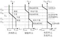
进一步地,所述直流母线电压所处区间包括5个运行区间:第1运行区间的直流母线电压条件为UL1<Udc<UH1,第2运行区间的直流母线电压条件为UH1<Udc<UH2,第3运行区间的直流母线电压条件为UL2<Udc<UL1,第4运行区间的直流母线电压条件为Udc>UH2,第5运行区间的直流母线电压条件为Udc<UL2;其中,Udc为直流母线电压,UL2、UL1、UH1、UH2分别为电压分层临界值。Further, the interval in which the DC bus voltage is located includes five operating intervals: the DC bus voltage condition in the first operating interval is UL1 <Udc <UH1 , and the DC bus voltage condition in the second operating interval is UH1 <Udc <UH2 , the DC bus voltage condition in the third operation interval is UL2 <Udc <UL1 , the DC bus voltage condition in the fourth operation interval is Udc >UH2 , and the DC bus voltage condition in the fifth operation interval is Udc <UL2 ; wherein, Udc is the DC bus voltage, and UL2 , UL1 , UH1 , and UH2 are the voltage stratification critical values, respectively.
各组成单元内部的本地控制器依据楼宇群直流配电系统直流母线电压所处区间,按照预设规则调整各自的工作模式,共同实现直流母线电压稳定和系统的正常运行,并在系统进入不正常或故障状态后保护关键设备和重要负荷。The local controllers inside each component unit adjust their respective working modes according to the preset rules according to the interval of the DC bus voltage of the DC power distribution system of the building group, so as to jointly realize the DC bus voltage stability and the normal operation of the system. or protect critical equipment and important loads after fault conditions.
需要说明的是,如图5所示,根据楼宇群直流配电网与交流主网的联络关系,楼宇群直流配电系统存在并网与离网两个基本运行方式,下面从这两种运行方式分别说明本地控制器的控制过程:It should be noted that, as shown in Figure 5, according to the connection between the DC distribution network of the building group and the AC main network, the DC distribution system of the building group has two basic operation modes: grid-connected and off-grid. The methods respectively describe the control process of the local controller:
(1)并网运行模式下:(1) In grid-connected operation mode:
当所述直流母线电压处于所述第1运行区间时,将并网单元端口作为松弛节点,采用下垂控制维持直流母线电压,实现系统稳定运行。此时光伏发电单元处于MPPT运行模式,最大限度消纳新能源,储能单元(包括蓄电池组和超级电容组)不工作或处于充放电恢复阶段;When the DC bus voltage is in the first operating interval, the port of the grid-connected unit is used as a slack node, and droop control is adopted to maintain the DC bus voltage, so as to realize the stable operation of the system. At this time, the photovoltaic power generation unit is in the MPPT operation mode, consuming new energy to the maximum extent, and the energy storage unit (including the battery bank and the super capacitor bank) is not working or is in the charging and discharging recovery stage;
当所述直流母线电压处于所述第2运行区间或第3运行区间时,此时并网端口达到功率极限,处于限流运行状态,输出恒定极限功率,系统偏差功率由储能单元提供。其中蓄电池组储能单元采用下垂控制,其端口流通功率与电压变化量满足预设下垂控制关系,超级电容储能单元补偿负荷与发电单元(含并网单元与光伏单元)功率差额的高频分量,对调节过程起支撑作用,光伏发电单元同样工作在MPPT运行模式,最大限度消纳新能源。When the DC bus voltage is in the second operating interval or the third operating interval, the grid-connected port reaches the power limit and is in a current-limiting operating state, outputting constant limit power, and the system deviation power is provided by the energy storage unit. Among them, the battery energy storage unit adopts droop control, and its port circulating power and voltage change meet the preset droop control relationship, and the super capacitor energy storage unit compensates for the high-frequency component of the power difference between the load and the power generation unit (including the grid-connected unit and the photovoltaic unit). , which supports the adjustment process. The photovoltaic power generation unit also works in the MPPT operation mode to maximize the consumption of new energy.
当所述直流母线电压处于所述第4运行区间时,楼宇群直流配电系统中储能单元和并网单元达到输入功率极限,处于限流运行状态,输入恒定极限功率。此时配电网系统各发电单元和储能单元输出功率大于负荷需求功率,光伏发电单元退出MPPT工作模式,进入恒压运行状态,向单元级控制器输出端口指令参考电压,承担维持直流母线电压的功能;When the DC bus voltage is in the fourth operating interval, the energy storage unit and the grid-connected unit in the DC power distribution system of the building group reach the input power limit, are in a current-limiting operation state, and input a constant limit power. At this time, the output power of each power generation unit and energy storage unit in the distribution network system is greater than the load demand power, the photovoltaic power generation unit exits the MPPT working mode, enters the constant voltage operation state, and outputs the port command reference voltage to the unit-level controller to maintain the DC bus voltage. function;
当所述直流母线电压处于所述第5运行区间时,楼宇群直流配电系统中储能单元和并网单元达到输出功率极限,处于限流运行状态,输出恒定极限功率。此时配电网系统各发电单元和储能单元输出功率小于负荷需求功率,该状态可能由于负荷短路性故障或剧烈变化导致,控制方法对负荷单元按照既定规则,遵循负荷优先级进行减负荷操作,使母线电压恢复正常运行区间。When the DC bus voltage is in the fifth operating interval, the energy storage unit and the grid-connected unit in the DC power distribution system of the building group reach the output power limit, are in a current-limiting operation state, and output a constant limit power. At this time, the output power of each power generation unit and energy storage unit in the distribution network system is less than the load demand power. This state may be caused by a short-circuit fault or a drastic change of the load. The control method performs the load shedding operation for the load unit according to the established rules and load priority. , so that the bus voltage returns to the normal operating range.
(2)离网运行模式下:(2) In off-grid operation mode:
当所述直流母线电压处于所述第1运行区间时,在储能单元容量处于正常状态时,将储能单元端口作为松弛节点,采用下垂控制方法控制所述直流母线电压,并控制发电单元处于MPPT运行模式;否则,将发电单元端口作为松弛节点,维持所述直流母线电压,储能单元处于不工作或充放电恢复阶段;When the DC bus voltage is in the first operating interval, when the capacity of the energy storage unit is in a normal state, the port of the energy storage unit is used as a slack node, the droop control method is used to control the DC bus voltage, and the power generation unit is controlled to be in the normal state. MPPT operation mode; otherwise, the power generation unit port is used as a slack node to maintain the DC bus voltage, and the energy storage unit is in the inactive or charge-discharge recovery stage;
当所述直流母线电压处于所述第2运行区间或第3运行区间时,将储能单元端口作为松弛节点,采用下垂控制方法维持所述直流母线电压,控制发电单元处于MPPT运行模式;When the DC bus voltage is in the second operating interval or the third operating interval, the port of the energy storage unit is used as a slack node, the droop control method is used to maintain the DC bus voltage, and the power generation unit is controlled to be in the MPPT operation mode;
当所述直流母线电压处于所述第4运行区间时,楼宇群直流配电系统中储能单元和并网单元达到输入功率极限,处于限流运行状态,输入恒定极限功率。此时配电网系统各发电单元和储能单元输出功率大于负荷需求功率,光伏发电单元退出MPPT工作模式,进入恒压运行状态,向单元级控制器输出端口指令参考电压,承担维持直流母线电压的功能;When the DC bus voltage is in the fourth operating interval, the energy storage unit and the grid-connected unit in the DC power distribution system of the building group reach the input power limit, are in a current-limiting operation state, and input a constant limit power. At this time, the output power of each power generation unit and energy storage unit in the distribution network system is greater than the load demand power, the photovoltaic power generation unit exits the MPPT working mode, enters the constant voltage operation state, and outputs the port command reference voltage to the unit-level controller to maintain the DC bus voltage. function;
当所述直流母线电压处于所述第5运行区间时,楼宇群直流配电系统中储能单元和并网单元达到输出功率极限,处于限流运行状态,输出恒定极限功率。此时配电网系统各发电单元和储能单元输出功率小于负荷需求功率,该状态可能由于负荷短路性故障或剧烈变化导致,控制方法对负荷单元按照既定规则,遵循负荷优先级进行减负荷操作,使母线电压恢复正常运行区间。When the DC bus voltage is in the fifth operating interval, the energy storage unit and the grid-connected unit in the DC power distribution system of the building group reach the output power limit, are in a current-limiting operation state, and output a constant limit power. At this time, the output power of each power generation unit and energy storage unit in the distribution network system is less than the load demand power. This state may be caused by a short-circuit fault or a drastic change of the load. The control method performs the load shedding operation for the load unit according to the established rules and load priority. , so that the bus voltage returns to the normal operating range.
需要说明的是,两者在配电系统控制方法上的区别主要体现在第1层区内松弛终端的选取。在系统并网运行时,若并网接口单元传输功率处于合理区间,将其作为松弛终端承担第1层区内的母线电压调节;在系统离网运行时,若系统存在储能单元且蓄电池组荷电状态正常时,将其作为松弛终端承担第1层区内的母线电压调节,否则采用分布式电源作为松弛终端。It should be noted that the difference between the two in the control method of the power distribution system is mainly reflected in the selection of the slack terminal in the first layer area. When the system is connected to the grid, if the transmission power of the grid-connected interface unit is in a reasonable range, it is used as a slack terminal to undertake the bus voltage regulation in the first layer area; when the system is off-grid, if the system has energy storage units and battery packs When the state of charge is normal, it is used as the slack terminal to undertake the bus voltage regulation in the first layer area, otherwise the distributed power supply is used as the slack terminal.
特别地,上述系统各个组成单元均应满足的恒压控制、恒流控制及恒功率控制等基础功能外,对于特定的系统组成单元,还具备适应于系统运行稳定性与经济性要求的特定功能。比如对于光伏发电单元,具备MPPT(最大功率跟踪)运行模式。在光伏发电单元基础恒压控制、恒流控制、恒功率控制的基础上,设置MPPT算法,其输出指令参考电压通过状态选择器后输入基础恒压控制方法,实现光伏发电单元的MPPT运行,保证特定场景下的新能源消纳最大化。对于楼宇群直流配电系统其他组成单元,包括但不限于并网单元、储能单元,可以通过在基础恒压控制、恒流控制、恒功率控制的控制结构基础上,设置额外惯性环节,实现附加惯性控制,从控制的角度进一步提高系统运行的稳定性。In particular, in addition to the basic functions such as constant voltage control, constant current control and constant power control that should be satisfied by each component of the above system, for a specific system component unit, it also has specific functions that meet the requirements of system operation stability and economy. . For example, for photovoltaic power generation units, there is an MPPT (maximum power tracking) operating mode. On the basis of the basic constant voltage control, constant current control, and constant power control of the photovoltaic power generation unit, the MPPT algorithm is set, and the output command reference voltage passes through the state selector and then enters the basic constant voltage control method to realize the MPPT operation of the photovoltaic power generation unit. Maximize new energy consumption in specific scenarios. For other components of the DC power distribution system of the building group, including but not limited to grid-connected units and energy storage units, additional inertia links can be set up on the basis of the basic control structures of constant voltage control, constant current control, and constant power control to achieve Additional inertial control further improves the stability of system operation from the control point of view.
进一步地,所述下垂控制方法通过下垂系数的调节确定系统响应单元变流器的等效输出阻抗,实现输出电流的调节和功率分配;Further, the droop control method determines the equivalent output impedance of the system response unit converter by adjusting the droop coefficient, so as to realize the adjustment of the output current and the power distribution;
所述楼宇群直流配电系统各组成单元端口直流电压的下垂特性表示如下:The droop characteristics of the DC voltage at the ports of each component unit of the DC power distribution system of the building group are expressed as follows:

其中,Udc为所述本地控制器输出指令参考电压,
进一步地,在上述步骤S2中,所述预设优化目标包括实现所述楼宇群直流配电系统运行电费最低和实现负荷恒功率控制,两个控制目标相互独立,由集中控制器根据电力系统发出的控制指令统一实现,该控制指令可为手动触发或自动调度给出。集中控制器的具体控制过程如图6所示:Further, in the above-mentioned step S2, the preset optimization goal includes realizing the lowest operating electricity cost of the DC power distribution system of the building group and realizing the load constant power control. The two control goals are independent of each other, and are issued by the centralized controller according to the power system. The control instructions of the system can be uniformly realized, and the control instructions can be given by manual triggering or automatic scheduling. The specific control process of the centralized controller is shown in Figure 6:
(1)在所述预设优化目标为实现所述楼宇群直流配电系统运行电费最低时:(1) When the preset optimization goal is to achieve the lowest operating electricity cost of the DC power distribution system of the building group:
(1-1)首先建立楼宇直流配电系统主要组成单元模型:对于负荷单元模型,包括:限时长不可中断负荷PA、可中断负荷PB、不可调度负荷PC。为达到精确控制负荷运行状态的目的,设置最小时间间隔为0.5h,由此将1天划分为48个运行控制区间。定义状态变量

其中,t表示运行控制时刻;N表示系统等效负荷数量。Among them, t represents the operation control time; N represents the equivalent load of the system.
对于光伏发电单元,主要考虑光照强度与温度对发电功率的影响,关系式如下For photovoltaic power generation units, the influence of light intensity and temperature on power generation is mainly considered, and the relationship is as follows
Ppv=ηSI[1-0.005(T+25)]Ppv =ηSI[1-0.005(T+25)]
其中,Ppv表示光伏发电单元输出功率;η表示光伏阵列的光电转换效率;S表示光伏阵列面板面积;I表示光照强度;T表示光伏阵列工作温度。Among them, Ppv represents the output power of the photovoltaic power generation unit; η represents the photoelectric conversion efficiency of the photovoltaic array; S represents the area of the photovoltaic array panel; I represents the light intensity; T represents the operating temperature of the photovoltaic array.
对于蓄电池组储能单元,其运行状态充放电时荷电状态的变化关系式如下For the battery energy storage unit, the change relationship of the state of charge when the operating state is charged and discharged is as follows

其中,SSOC(t)为t时刻蓄电池组的荷电状态;Cr为实际电荷容量;CN为标称电荷容量;ηch为蓄电池组的充电效率;ηdis为蓄电池组的放电效率;Pch(t)为t时刻蓄电池组的充电功率;Pdis(t)为t时刻蓄电池组的放电功率;Δt为运行时长。Among them, SSOC (t) is the state of charge of the battery pack at timet ; Cr is the actual charge capacity;CN is the nominal charge capacity;ηch is the charging efficiency of the battery pack;ηdis is the discharge efficiency of the battery pack; Pch (t) is the charging power of the battery pack at time t; Pdis (t) is the discharge power of the battery pack at time t; Δt is the running time.
(1-2)构建所述楼宇群直流配电系统运行电费最低优化目标函数及约束条件,其中:(1-2) Constructing the optimal objective function and constraint conditions for the minimum operating electricity cost of the DC power distribution system of the building group, wherein:
优化目标函数为:The optimization objective function is:
minf1=Cbuy-Csellminf1 =Cbuy -Csell


其中,


约束条件为:The constraints are:
功率平衡约束:Power Balance Constraints:

其中,


蓄电池组电量状态约束:Constraints on the state of charge of the battery pack:
SSOCmin≤SSOC(t)≤SSOCmaxSSOCmin ≤SSOC (t)≤SSOCmax
其中,SSOCmin为蓄电池组荷电状态最小值;SSOCmax为蓄电池组荷电状态最大值;SSOC(t)为t时刻蓄电池组的荷电状态;Among them, SSOCmin is the minimum state of charge of the battery pack; SSOCmax is the maximum state of charge of the battery pack; SSOC (t) is the state of charge of the battery pack at time t;
系统各组成单元传输功率约束:Transmission power constraints of each component of the system:

其中,Pit表示楼宇群直流配电系统各组成单元在t时刻的传输功率;

(1-3)采用离散二进制粒子群优化算法求解所述运行电费最低优化目标函数,得到所述楼宇群直流配电系统中负荷单元的工作状态指令,并输出至对应负荷单元的单元级控制器,实现系统的运行电费最低优化控制,其中:(1-3) Use the discrete binary particle swarm optimization algorithm to solve the objective function of the minimum operating electricity cost, obtain the working state command of the load unit in the DC power distribution system of the building group, and output it to the unit-level controller of the corresponding load unit , to achieve the lowest optimal control of the operating electricity cost of the system, where:
所述离散二进制粒子群优化算法的速度更新公式为:The speed update formula of the discrete binary particle swarm optimization algorithm is:

其中,


利用修正sigmoid函数作为映射函数,将速度值映射为[0,1]的概率,表示粒子位置状态发生改变的机会:Using the modified sigmoid function as the mapping function, the probability of mapping the velocity value to [0,1] represents the chance of the particle position state changing:


其中,

其中,在每个新的迭代周期按照下式更新惯性权重:Among them, the inertia weight is updated according to the following formula in each new iteration cycle:

其中,ωmax为最大惯性权重;ωmin为最小惯性权重;K为预设的迭代次数;k为当前迭代数。Among them, ωmax is the maximum inertia weight; ωmin is the minimum inertia weight; K is the preset number of iterations; k is the current number of iterations.
需要说明的是,楼宇群直流配电系统的配网级优化控制方法以48个时间段的光伏发电单元历史和预测数据、电价、不可调度负荷功率、上网电价、可调负荷的工作功率作为输入参数,通过离散二级制粒子群优化算法,输出系统各负荷单元工作状态指令,并在优化控制条件触发的条件下输入对应负荷单元的单元级控制器,实现系统运行电费最低优化控制。It should be noted that the distribution network-level optimization control method of the DC power distribution system of the building group takes the historical and forecast data of photovoltaic power generation units in 48 time periods, electricity price, unschedulable load power, on-grid electricity price, and adjustable load working power as input. The parameters, through the discrete two-stage particle swarm optimization algorithm, output the working state instructions of each load unit in the system, and input the unit-level controller of the corresponding load unit under the condition of triggering the optimal control condition, so as to realize the optimal control of the lowest electricity cost in the system operation.
(2)在所述预设优化目标为实现负荷恒功率控制时:(2) When the preset optimization objective is to realize load constant power control:
集中控制器接收电力系统上级调度给出指令或手动触发,所述集中控制器在采样系统各组成单元输出功率的情况下,依照如下关系控制对应负荷单元的单元级控制器,实现系统的负荷恒功率控制:The centralized controller receives instructions or manual triggers from the upper-level scheduling of the power system. When the output power of each component unit of the sampling system is sampled, the centralized controller controls the unit-level controller of the corresponding load unit according to the following relationship, so as to realize the constant load of the system. Power Control:
Pes=PL-Ppv-PGPes =PL -Ppv -PG
PG=CPG = C
其中,Pes为系统储能单元输出功率;Ppv为系统光伏发电单元输出功率;PG为系统并网单元输出功率;C为制定恒功率参考值;PL为楼宇群直流配电系统负荷总功率。Among them, Pes is the output power of the energy storage unit of the system; Ppv is the output power of the photovoltaic power generation unit of the system;PG is the output power of the grid-connected unit of the system; C is the constant power reference value;PL is the load of the DC power distribution system of the building group total power.
需要说明的是,输出系统储能单元输出功率参考值,并在优化控制条件触发的条件下输入对应负荷单元的单元级控制器,实现楼宇群直流配电网的负荷恒功率控制。其中,对于集中控制器输出的储能单元输出功率指令参考值,其由高频分量和低频分量两部分构成,其中高频分量部分由超级电容组储能单元承担,低频分量部分由蓄电池组储能单元承担,实现控制目标。It should be noted that the output power reference value of the energy storage unit of the system is output, and the unit-level controller of the corresponding load unit is input to the unit-level controller of the corresponding load unit under the condition of triggering the optimal control condition to realize the load constant power control of the DC distribution network of the building group. Among them, the output power command reference value of the energy storage unit output by the centralized controller is composed of two parts: high frequency component and low frequency component, of which the high frequency component is borne by the supercapacitor energy storage unit, and the low frequency component is stored by the battery pack. It can be undertaken by the unit to achieve the control goal.
需要说明的是,本实施例中的楼宇群直流配电系统的协调控制过程,具备功率控制和母线电压调节两种基本功能,基于直流母线电压信号即可实现对楼宇群直流配电系统的稳定性控制,在采样实时状态数据和历史参考数据的基础上实现系统优化控制,控制方法架构清晰、易于实现;且采用了本地分散控制与优化集中控制相结合的集散协调控制方法架构,二者相互协调、互为补充,通过状态触发条件进行切换,极大的提高了控制系统综合性能;另外本方案具备较强的通用性和进一步扩展的能力,针对楼宇群直流配电系统的新特性与多样性,配网级优化控制方法具备宽范围、多角度优化能力,且可进一步接受上级调度指令,实现灵活运行。It should be noted that the coordinated control process of the DC power distribution system of the building group in this embodiment has two basic functions of power control and bus voltage regulation, and the stability of the DC power distribution system of the building group can be realized based on the DC bus voltage signal. Based on sampling real-time state data and historical reference data, system optimization control is realized, and the control method structure is clear and easy to implement; and the distributed coordinated control method structure combining local decentralized control and optimized centralized control is adopted. Coordinating and complementing each other, switching through state trigger conditions greatly improves the comprehensive performance of the control system; in addition, this solution has strong versatility and further expansion capabilities, aiming at the new characteristics and diversity of DC power distribution systems in buildings. The distribution network-level optimization control method has wide-range and multi-angle optimization capabilities, and can further accept higher-level scheduling instructions to achieve flexible operation.
本实施例还公开了一种楼宇群直流配电系统的集散协调控制系统,包括集中控制器、所述楼宇群直流配电系统的各组成单元对应的单元级控制器以及布置在各组成单元内的本地控制器,所述楼宇群直流配电系统的各组成单元均与直流三线制母线相连;各组成单元对应的单元级控制器接收本地控制器输出的控制指令,以控制各对应组成单元的直流母线端口物理量跟踪控制指令的响应给定的对应物理量参考值,实现各组成单元端口的恒压、恒流和恒功率控制;各组成单元对应的单元级控制器接收集中控制器输出的目标优化指令,以控制各对应组成单元的优化目标达到优化结果。This embodiment also discloses a distributed coordination control system for a DC power distribution system of a building group, including a centralized controller, a unit-level controller corresponding to each component unit of the building group DC power distribution system, and a controller arranged in each component unit. Each component unit of the DC power distribution system of the building group is connected to the DC three-wire busbar; the unit-level controller corresponding to each component unit receives the control instructions output by the local controller to control the operation of each corresponding component unit. The physical quantity of the DC bus port tracks the corresponding physical quantity reference value given by the response of the control command, and realizes the constant voltage, constant current and constant power control of each component unit port; the unit-level controller corresponding to each component unit receives the output of the centralized controller. Target optimization instruction to control the optimization goal of each corresponding component unit to achieve the optimization result.
本实施例依据各组成单元变流器拓扑结构与特性,以及不同组成单元的端口输入输出特性,建立每个单元相应的单元级控制器,其基于楼宇群直流配电系统运行稳定性和经济性的要求,同时具备恒压控制、恒流控制和恒功率控制三种运行模式。其中,单元级控制器的关键结构为典型PI控制器(图4示出了光伏发电单元对应的单元级控制器结构)。单元级控制器作为本地控制器和集中控制器的基础和响应,工作模式依据本地控制器和集中控制器输出状态指令实时切换;本地控制器和集中控制器层次相同,均高于单元级控制器,用于向单元级控制器输出控制指令,并通过状态选择结构实现本地控制器和集中控制器的执行状态。In this embodiment, a unit-level controller corresponding to each unit is established according to the converter topology and characteristics of each component unit, as well as the port input and output characteristics of different component units, which is based on the operation stability and economy of the DC power distribution system of the building group. It has three operating modes: constant voltage control, constant current control and constant power control. The key structure of the unit-level controller is a typical PI controller (Fig. 4 shows the structure of the unit-level controller corresponding to the photovoltaic power generation unit). The unit-level controller acts as the basis and response of the local controller and the centralized controller, and the working mode switches in real time according to the output state instructions of the local controller and the centralized controller; the local controller and the centralized controller have the same level and are higher than the unit-level controller. , which is used to output control instructions to the unit-level controller, and realize the execution state of the local controller and the centralized controller through the state selection structure.
具体来说,如图3所示,单元级控制器用于对各组成单元与直流母线连接端口进行恒压控制、恒流控制和恒功率控制;在接收本地控制器或集中控制器的输出控制指令后,使各个组成单元的直流母线端口物理量跟踪上级控制指令的响应给定的对应物理量参考值,包括端口电压大小、输入(输出)电流大小、输入(输出)功率大小,实现楼宇群直流配电系统各个组成单元端口的恒压、恒流、恒功率控制。Specifically, as shown in Figure 3, the unit-level controller is used to perform constant voltage control, constant current control and constant power control on the connection ports of each component unit and the DC bus; after receiving the output control instructions from the local controller or the centralized controller Then, make the physical quantity of the DC bus port of each constituent unit track the corresponding physical quantity reference value given by the response of the upper-level control command, including the port voltage, input (output) current, and input (output) power, so as to realize the DC power distribution of the building group. Constant voltage, constant current and constant power control of each component port of the system.
由集中控制器计算得到的系统各组成单元功率优化结果,在系统优化运行满足条件出发的前提下,作为控制指令传输至对应单元级控制方法结构执行,使系统各组成单元运行功率情况达到优化条件,实现上述优化目标和楼宇群直流配电系统的优化运行。The power optimization results of each component of the system calculated by the centralized controller, on the premise that the optimal operation of the system satisfies the conditions, are transmitted as control commands to the corresponding unit-level control method structure for execution, so that the operating power of each component of the system can reach the optimization conditions. , to achieve the above optimization goals and the optimal operation of the DC power distribution system of the building group.
进一步地,所述直流母线电压所处区间包括5个运行区间:第1运行区间的直流母线电压条件为UL1<Udc<UH1,第2运行区间的直流母线电压条件为UH1<Udc<UH2,第3运行区间的直流母线电压条件为UL2<Udc<UL1,第4运行区间的直流母线电压条件为Udc>UH2,第5运行区间的直流母线电压条件为Udc<UL2;其中,Udc为直流母线电压,UL2、UL1、UH1、UH2分别为电压分层临界值。Further, the interval in which the DC bus voltage is located includes five operating intervals: the DC bus voltage condition in the first operating interval is UL1 <Udc <UH1 , and the DC bus voltage condition in the second operating interval is UH1 <Udc <UH2 , the DC bus voltage condition in the third operation interval is UL2 <Udc <UL1 , the DC bus voltage condition in the fourth operation interval is Udc >UH2 , and the DC bus voltage condition in the fifth operation interval is Udc <UL2 ; wherein, Udc is the DC bus voltage, and UL2 , UL1 , UH1 , and UH2 are the voltage stratification critical values, respectively.
进一步地,所述本地控制器包括并网控制模块和离网控制模块,其中:Further, the local controller includes a grid-connected control module and an off-grid control module, wherein:
并网控制模块用于在并网运行模式下,根据直流母线电压所处区间,调整相应单元级控制器的运行模式;The grid-connected control module is used to adjust the operation mode of the corresponding unit-level controller according to the interval of the DC bus voltage in the grid-connected operation mode;
离网控制模块用于在离网运行模式下,根据直流母线电压所处区间,调整相应单元级控制器的运行模式。The off-grid control module is used to adjust the operation mode of the corresponding unit-level controller according to the interval of the DC bus voltage in the off-grid operation mode.
进一步地,所述并网控制模块包括第一并网控制单元、第二并网控制单元、第三并网控制单元、第四并网控制单元以及第五并网控制单元;Further, the grid-connected control module includes a first grid-connected control unit, a second grid-connected control unit, a third grid-connected control unit, a fourth grid-connected control unit, and a fifth grid-connected control unit;
第一并网控制单元用于当所述直流母线电压处于所述第1运行区间时,将并网单元端口作为松弛节点,采用下垂控制方法控制所述直流母线电压,并控制发电单元处于MPPT运行模式,储能单元处于不工作或充放电恢复阶段The first grid-connected control unit is configured to use the port of the grid-connected unit as a slack node when the DC bus voltage is in the first operating interval, use a droop control method to control the DC bus voltage, and control the power generation unit to be in MPPT operation mode, the energy storage unit is in the non-working or charging and discharging recovery stage
第二并网控制单元以及第三并网控制单元分别用于当所述直流母线电压处于所述第2运行区间或第3运行区间时,由储能单元采用下垂控制方法控制并网单元端口流通功率与电压变化量满足预设下垂控制关系,并补偿系统偏差功率,使并网单元端口输出恒定极限功率,以及控制发电单元处于MPPT运行模式;The second grid-connected control unit and the third grid-connected control unit are respectively configured to control the port flow of the grid-connected unit by the energy storage unit using the droop control method when the DC bus voltage is in the second operating interval or the third operating interval. The power and voltage changes meet the preset droop control relationship, and compensate the system deviation power, so that the port of the grid-connected unit outputs a constant limit power, and controls the power generation unit to be in the MPPT operation mode;
第四并网控制单元用于当所述直流母线电压处于所述第4运行区间时,控制发电单元退出MPPT工作模式,进入恒压运行状态,并向所述单元级控制器输出端口指令参考电压,维持所述直流母线电压;The fourth grid-connected control unit is used to control the power generation unit to exit the MPPT operation mode and enter the constant voltage operation state when the DC bus voltage is in the fourth operation interval, and output a port command reference voltage to the unit-level controller , maintaining the DC bus voltage;
第五并网控制单元用于当所述直流母线电压处于所述第5运行区间时,控制负荷单元遵循负荷优先级进行减负荷操作,使母线电压恢复正常运行区间。The fifth grid-connected control unit is configured to control the load unit to perform a load shedding operation according to the load priority when the DC bus voltage is in the fifth operating interval, so as to restore the bus voltage to the normal operating interval.
进一步地,所述离网控制模块包括第一离网控制单元、第二离网控制单元、第三离网控制单元、第四离网控制单元以及第五离网控制单元;Further, the off-grid control module includes a first off-grid control unit, a second off-grid control unit, a third off-grid control unit, a fourth off-grid control unit, and a fifth off-grid control unit;
第一离网控制单元用于当所述直流母线电压处于所述第1运行区间时,在储能单元容量处于正常状态时,将储能单元端口作为松弛节点,采用下垂控制方法控制所述直流母线电压,并控制发电单元处于MPPT运行模式;否则,将发电单元端口作为松弛节点,维持所述直流母线电压,储能单元处于不工作或充放电恢复阶段;The first off-grid control unit is configured to use a droop control method to control the direct current by using the port of the energy storage unit as a slack node when the DC bus voltage is in the first operating interval and when the capacity of the energy storage unit is in a normal state bus voltage, and control the power generation unit to be in the MPPT operation mode; otherwise, the power generation unit port is used as a slack node to maintain the DC bus voltage, and the energy storage unit is in the inactive or charge-discharge recovery stage;
第二离网控制单元、第三离网控制单元分别用于当所述直流母线电压处于所述第2运行区间或第3运行区间时,将储能单元端口作为松弛节点,采用下垂控制方法维持所述直流母线电压,控制发电单元处于MPPT运行模式;The second off-grid control unit and the third off-grid control unit are respectively configured to use the droop control method to maintain the port of the energy storage unit as a slack node when the DC bus voltage is in the second operating interval or the third operating interval. The DC bus voltage controls the power generation unit to be in the MPPT operation mode;
第四离网控制单元用于当所述直流母线电压处于所述第4运行区间时,控制发电单元退出MPPT工作模式,进入恒压运行状态,并向所述单元级控制器输出端口指令参考电压,维持所述直流母线电压;The fourth off-grid control unit is used to control the power generation unit to exit the MPPT operation mode and enter the constant voltage operation state when the DC bus voltage is in the fourth operation interval, and output a port command reference voltage to the unit-level controller , maintaining the DC bus voltage;
第五离网控制单元用于当所述直流母线电压处于所述第5运行区间时,控制负荷单元遵循负荷优先级进行减负荷操作,使母线电压恢复正常运行区间。The fifth off-grid control unit is configured to control the load unit to perform a load shedding operation according to the load priority when the DC bus voltage is in the fifth operating interval, so as to restore the bus voltage to the normal operating interval.
进一步地,所述预设优化目标包括实现所述楼宇群直流配电系统运行电费最低和实现负荷恒功率控制,所述集中控制器包括电费控制模块和功率控制模块;Further, the preset optimization goal includes realizing the lowest operating electricity cost of the DC power distribution system of the building group and realizing the constant power control of the load, and the centralized controller includes an electricity cost control module and a power control module;
其中,电费控制模块包括函数构建单元和电费最低优化单元;Among them, the electricity rate control module includes a function construction unit and a minimum electricity rate optimization unit;
函数构建单元用于构建所述楼宇群直流配电系统运行电费最低优化目标函数及约束条件;The function construction unit is used for constructing the optimal objective function and constraint conditions for the minimum operating electricity cost of the DC power distribution system of the building group;
电费最低优化单元用于采用离散二进制粒子群优化算法求解所述运行电费最低优化目标函数,得到所述楼宇群直流配电系统中负荷单元的工作状态指令,并输出至对应负荷单元的单元级控制器,实现系统的运行电费最低优化控制。The minimum electricity cost optimization unit is used to solve the objective function of the minimum operating electricity cost optimization by using the discrete binary particle swarm optimization algorithm, obtain the working state command of the load unit in the DC power distribution system of the building group, and output it to the unit-level control of the corresponding load unit The device realizes the lowest optimal control of the operating electricity cost of the system.
其中,所述运行电费最低优化目标函数及约束条件为:Wherein, the objective function and constraint conditions for the minimum operating electricity cost optimization are:
优化目标函数为:The optimization objective function is:
minf1=Cbuy-Csellminf1 =Cbuy -Csell


其中,


约束条件为:The constraints are:
功率平衡约束:Power Balance Constraints:

其中,


蓄电池组电量状态约束:Constraints on the state of charge of the battery pack:
SSOCmin≤SSOC(t)≤SSOCmaxSSOCmin ≤SSOC (t)≤SSOCmax
其中,SSOCmin为蓄电池组荷电状态最小值;SSOCmax为蓄电池组荷电状态最大值;SSOC(t)为t时刻蓄电池组的荷电状态;Among them, SSOCmin is the minimum state of charge of the battery pack; SSOCmax is the maximum state of charge of the battery pack; SSOC (t) is the state of charge of the battery pack at time t;
系统各组成单元传输功率约束:Transmission power constraints of each component of the system:

其中,Pit表示楼宇群直流配电系统各组成单元在t时刻的传输功率;

其中,所述离散二进制粒子群优化算法的速度更新公式为:Wherein, the speed update formula of the discrete binary particle swarm optimization algorithm is:

其中,


利用修正sigmoid函数作为映射函数,将速度值映射为[0,1]的概率,表示粒子位置状态发生改变的机会:Using the modified sigmoid function as the mapping function, the probability of mapping the velocity value to [0,1] represents the chance of the particle position state changing:


其中,

进一步地,所述功率控制模块用于接收电力系统发出的控制指令,采样系统各组成单元的输出功率,依照如下关系控制对应负荷单元的单元级控制器,实现系统的负荷恒功率控制:Further, the power control module is used to receive the control command sent by the power system, sample the output power of each component unit of the system, and control the unit-level controller of the corresponding load unit according to the following relationship, so as to realize the load constant power control of the system:
Pes=PL-Ppv-PGPes =PL -Ppv -PG
PG=CPG = C
其中,Pes为系统储能单元输出功率;Ppv为系统光伏发电单元输出功率;PG为系统并网单元输出功率;C为制定恒功率参考值;PL为楼宇群直流配电系统负荷总功率。Among them, Pes is the output power of the energy storage unit of the system; Ppv is the output power of the photovoltaic power generation unit of the system;PG is the output power of the grid-connected unit of the system; C is the constant power reference value;PL is the load of the DC power distribution system of the building group total power.
本方案通过单元级控制器、本地控制器、集中控制器三个部分构成和实现,保证楼宇群直流配电系统运行的长期稳定性和经济最优性,层次清晰、方法明确,且具备应用于多种场景和接收上级调度及能量管理的能力。This scheme is composed and realized by three parts: unit-level controller, local controller and centralized controller, to ensure the long-term stability and economic optimality of the operation of the DC power distribution system of the building group. A variety of scenarios and the ability to receive superior scheduling and energy management.
本领域内的技术人员应明白,本申请的实施例可提供为方法、系统、或计算机程序产品。因此,本申请可采用完全硬件实施例、完全软件实施例、或结合软件和硬件方面的实施例的形式。而且,本申请可采用在一个或多个其中包含有计算机可用程序代码的计算机可用存储介质(包括但不限于磁盘存储器、CD-ROM、光学存储器等)上实施的计算机程序产品的形式。As will be appreciated by those skilled in the art, the embodiments of the present application may be provided as a method, a system, or a computer program product. Accordingly, the present application may take the form of an entirely hardware embodiment, an entirely software embodiment, or an embodiment combining software and hardware aspects. Furthermore, the present application may take the form of a computer program product embodied on one or more computer-usable storage media (including, but not limited to, disk storage, CD-ROM, optical storage, etc.) having computer-usable program code embodied therein.
本申请是参照根据本申请实施例的方法、设备(系统)、和计算机程序产品的流程图和/或方框图来描述的。应理解可由计算机程序指令实现流程图和/或方框图中的每一流程和/或方框、以及流程图和/或方框图中的流程和/或方框的结合。可提供这些计算机程序指令到通用计算机、专用计算机、嵌入式处理机或其他可编程数据处理设备的处理器以产生一个机器,使得通过计算机或其他可编程数据处理设备的处理器执行的指令产生用于实现在流程图一个流程或多个流程和/或方框图一个方框或多个方框中指定的功能的装置。The present application is described with reference to flowchart illustrations and/or block diagrams of methods, apparatus (systems), and computer program products according to embodiments of the present application. It will be understood that each flow and/or block in the flowchart illustrations and/or block diagrams, and combinations of flows and/or blocks in the flowchart illustrations and/or block diagrams, can be implemented by computer program instructions. These computer program instructions may be provided to the processor of a general purpose computer, special purpose computer, embedded processor or other programmable data processing device to produce a machine such that the instructions executed by the processor of the computer or other programmable data processing device produce Means for implementing the functions specified in a flow or flow of a flowchart and/or a block or blocks of a block diagram.
这些计算机程序指令也可存储在能引导计算机或其他可编程数据处理设备以特定方式工作的计算机可读存储器中,使得存储在该计算机可读存储器中的指令产生包括指令装置的制造品,该指令装置实现在流程图一个流程或多个流程和/或方框图一个方框或多个方框中指定的功能。These computer program instructions may also be stored in a computer-readable memory capable of directing a computer or other programmable data processing apparatus to function in a particular manner, such that the instructions stored in the computer-readable memory result in an article of manufacture comprising instruction means, the instructions The apparatus implements the functions specified in the flow or flow of the flowcharts and/or the block or blocks of the block diagrams.
这些计算机程序指令也可装载到计算机或其他可编程数据处理设备上,使得在计算机或其他可编程设备上执行一系列操作步骤以产生计算机实现的处理,从而在计算机或其他可编程设备上执行的指令提供用于实现在流程图一个流程或多个流程和/或方框图一个方框或多个方框中指定的功能的步骤。These computer program instructions can also be loaded on a computer or other programmable data processing device to cause a series of operational steps to be performed on the computer or other programmable device to produce a computer-implemented process such that The instructions provide steps for implementing the functions specified in the flow or blocks of the flowcharts and/or the block or blocks of the block diagrams.
以上所述仅为本发明的较佳实施例,并不用以限制本发明,凡在本发明的精神和原则之内,所作的任何修改、等同替换、改进等,均应包含在本发明的保护范围之内。The above are only preferred embodiments of the present invention and are not intended to limit the present invention. Any modifications, equivalent replacements, improvements, etc. made within the spirit and principles of the present invention shall be included in the protection of the present invention. within the range.
Claims (20)


Priority Applications (1)
| Application Number | Priority Date | Filing Date | Title |
|---|---|---|---|
| CN202010432113.4ACN111525621B (en) | 2020-05-20 | 2020-05-20 | Distributed coordination control method and system for building group direct current power distribution system |
Applications Claiming Priority (1)
| Application Number | Priority Date | Filing Date | Title |
|---|---|---|---|
| CN202010432113.4ACN111525621B (en) | 2020-05-20 | 2020-05-20 | Distributed coordination control method and system for building group direct current power distribution system |
Publications (2)
| Publication Number | Publication Date |
|---|---|
| CN111525621Atrue CN111525621A (en) | 2020-08-11 |
| CN111525621B CN111525621B (en) | 2021-06-18 |
Family
ID=71909194
Family Applications (1)
| Application Number | Title | Priority Date | Filing Date |
|---|---|---|---|
| CN202010432113.4AActiveCN111525621B (en) | 2020-05-20 | 2020-05-20 | Distributed coordination control method and system for building group direct current power distribution system |
Country Status (1)
| Country | Link |
|---|---|
| CN (1) | CN111525621B (en) |
Cited By (5)
| Publication number | Priority date | Publication date | Assignee | Title |
|---|---|---|---|---|
| CN112271716A (en)* | 2020-10-22 | 2021-01-26 | 珠海格力电器股份有限公司 | Power supply system for improving startup stability, control method thereof, and air conditioning unit |
| CN112415963A (en)* | 2020-11-13 | 2021-02-26 | 珠海格力电器股份有限公司 | Building-level energy control method, control device and system and processor |
| CN112467793A (en)* | 2020-11-25 | 2021-03-09 | 国网安徽省电力有限公司经济技术研究院 | Low-voltage flexible direct-current power distribution system and method for building group |
| CN114448072A (en)* | 2022-01-28 | 2022-05-06 | 北京动科瑞利文科技有限公司 | DC building power supply system and its operation method |
| CN117060422A (en)* | 2023-10-11 | 2023-11-14 | 江苏省电力试验研究院有限公司 | Light storage direct-flexible building control method, system, computer equipment and storage medium |
Citations (10)
| Publication number | Priority date | Publication date | Assignee | Title |
|---|---|---|---|---|
| WO2003075427A1 (en)* | 2002-03-06 | 2003-09-12 | Matsushita Electric Industrial Co., Ltd. | Setting device of distributed energy supply system |
| WO2011162576A2 (en)* | 2010-06-25 | 2011-12-29 | 엘지전자 주식회사 | Network system |
| US20120166001A1 (en)* | 2010-12-23 | 2012-06-28 | Kt Corporation | Method and system for providing energy management in smart grid environment, electrical power producing apparatus in smart grid environment |
| US8639392B2 (en)* | 2008-09-29 | 2014-01-28 | Battelle Memorial Institute | Electric power grid control using a market-based resource allocation system |
| EP2858015A1 (en)* | 2013-10-04 | 2015-04-08 | Building Research Establishment Ltd | System and method for simulation, control and performance monitoring of energy systems |
| CN105226632A (en)* | 2015-10-30 | 2016-01-06 | 上海电力学院 | A kind of multi-mode of DC micro power grid system switches control method for coordinating |
| CN108471109A (en)* | 2018-04-24 | 2018-08-31 | 清华大学 | The univesral distribution formula control method and system of the more micro-grid systems of direct current |
| CN108667147A (en)* | 2018-06-15 | 2018-10-16 | 贵州电网有限责任公司 | Straightening stream distribution center Optimization Scheduling in a kind of flexibility containing more micro-capacitance sensors |
| US10169832B2 (en)* | 2013-05-08 | 2019-01-01 | Instant Access Networks, Llc | Method and instrumentation for sustainable energy load flow management system performing as resilient adaptive microgrid system |
| CN110212517A (en)* | 2019-06-24 | 2019-09-06 | 东南大学 | The distributing unified control method of mesolow direct-flow distribution system |
- 2020
- 2020-05-20CNCN202010432113.4Apatent/CN111525621B/enactiveActive
Patent Citations (10)
| Publication number | Priority date | Publication date | Assignee | Title |
|---|---|---|---|---|
| WO2003075427A1 (en)* | 2002-03-06 | 2003-09-12 | Matsushita Electric Industrial Co., Ltd. | Setting device of distributed energy supply system |
| US8639392B2 (en)* | 2008-09-29 | 2014-01-28 | Battelle Memorial Institute | Electric power grid control using a market-based resource allocation system |
| WO2011162576A2 (en)* | 2010-06-25 | 2011-12-29 | 엘지전자 주식회사 | Network system |
| US20120166001A1 (en)* | 2010-12-23 | 2012-06-28 | Kt Corporation | Method and system for providing energy management in smart grid environment, electrical power producing apparatus in smart grid environment |
| US10169832B2 (en)* | 2013-05-08 | 2019-01-01 | Instant Access Networks, Llc | Method and instrumentation for sustainable energy load flow management system performing as resilient adaptive microgrid system |
| EP2858015A1 (en)* | 2013-10-04 | 2015-04-08 | Building Research Establishment Ltd | System and method for simulation, control and performance monitoring of energy systems |
| CN105226632A (en)* | 2015-10-30 | 2016-01-06 | 上海电力学院 | A kind of multi-mode of DC micro power grid system switches control method for coordinating |
| CN108471109A (en)* | 2018-04-24 | 2018-08-31 | 清华大学 | The univesral distribution formula control method and system of the more micro-grid systems of direct current |
| CN108667147A (en)* | 2018-06-15 | 2018-10-16 | 贵州电网有限责任公司 | Straightening stream distribution center Optimization Scheduling in a kind of flexibility containing more micro-capacitance sensors |
| CN110212517A (en)* | 2019-06-24 | 2019-09-06 | 东南大学 | The distributing unified control method of mesolow direct-flow distribution system |
Non-Patent Citations (1)
| Title |
|---|
| 鲍薇: "多电压源型微源组网的微电网运行控制与能量管理策略研究", 《中国博士学位论文全文数据库 工程科技II辑》* |
Cited By (7)
| Publication number | Priority date | Publication date | Assignee | Title |
|---|---|---|---|---|
| CN112271716A (en)* | 2020-10-22 | 2021-01-26 | 珠海格力电器股份有限公司 | Power supply system for improving startup stability, control method thereof, and air conditioning unit |
| CN112415963A (en)* | 2020-11-13 | 2021-02-26 | 珠海格力电器股份有限公司 | Building-level energy control method, control device and system and processor |
| CN112415963B (en)* | 2020-11-13 | 2022-02-08 | 珠海格力电器股份有限公司 | Building-level energy control method, control device and system and processor |
| CN112467793A (en)* | 2020-11-25 | 2021-03-09 | 国网安徽省电力有限公司经济技术研究院 | Low-voltage flexible direct-current power distribution system and method for building group |
| CN114448072A (en)* | 2022-01-28 | 2022-05-06 | 北京动科瑞利文科技有限公司 | DC building power supply system and its operation method |
| CN117060422A (en)* | 2023-10-11 | 2023-11-14 | 江苏省电力试验研究院有限公司 | Light storage direct-flexible building control method, system, computer equipment and storage medium |
| CN117060422B (en)* | 2023-10-11 | 2024-01-19 | 江苏省电力试验研究院有限公司 | A light-storage direct-flexible building control method, system, computer equipment and storage medium |
Also Published As
| Publication number | Publication date |
|---|---|
| CN111525621B (en) | 2021-06-18 |
Similar Documents
| Publication | Publication Date | Title |
|---|---|---|
| CN111525621B (en) | Distributed coordination control method and system for building group direct current power distribution system | |
| CN108470239B (en) | Active power distribution network multi-target layered planning method considering demand side management and energy storage | |
| CN105552940B (en) | Distributed global optimum's EMS based on alternating direction Multiplier Algorithm | |
| CN107546781B (en) | Multi-objective operation optimization method of microgrid based on improved PSO algorithm | |
| CN112380694B (en) | An optimal planning method for distribution network based on differentiated reliability requirements | |
| CN110956324B (en) | A day-ahead high-dimensional objective optimal scheduling method for active distribution network based on improved MOEA/D | |
| CN108667147B (en) | Optimized dispatching method for flexible medium-voltage direct-current power distribution center with multiple micro-grids | |
| CN108736509A (en) | A kind of active distribution network multi-source coordinating and optimizing control method and system | |
| Azizipanah-Abarghooee et al. | Modified shuffled frog leaping algorithm for multi-objective optimal power flow with FACTS devices | |
| CN116307087B (en) | Micro-grid system energy storage optimal configuration method and system considering charging and discharging of electric automobile | |
| Nemati et al. | Optimization of microgrids short term operation based on an enhanced genetic algorithm | |
| CN110034571A (en) | A kind of distributed energy storage addressing constant volume method considering renewable energy power output | |
| Aiswariya et al. | Optimal microgrid battery scheduling using simulated annealing | |
| Wu et al. | Optimized capacity configuration of an integrated power system of wind, photovoltaic and energy storage device based on improved particle swarm optimizer | |
| Corso et al. | Multi-objective long term optimal dispatch of distributed energy resources in micro-grids | |
| CN114781755A (en) | UPQC capacity optimization method for photovoltaic energy storage microgrid | |
| CN119378755A (en) | A method and system for calculating virtual inertia of network-building new energy power generation equipment | |
| CN118713138A (en) | A coordinated control method for photovoltaic energy storage system | |
| Li et al. | Energy optimization management strategy for DC nano-grid cluster with high comprehensive energy efficiency | |
| CN109119988B (en) | Photovoltaic-battery microgrid energy scheduling management method based on dynamic wholesale market price | |
| CN118174311A (en) | Reactive power optimization method and system for power distribution network considering uncertainty of source load | |
| Ramesh et al. | Cost optimization by integrating PV-System and battery energy storage system into microgrid using particle swarm optimization | |
| Benoit et al. | Deterministic optimal power flow for smart grid short-term predictive energy management | |
| Vinothkumar et al. | Efficient Power Management and Control Strategy of Hybrid Renewable Energy System in Microgrid | |
| Hou | Simulation of Electrical Power System Reserve Capacity Optimization Model Based on Differential Evolution Algorithm |
Legal Events
| Date | Code | Title | Description |
|---|---|---|---|
| PB01 | Publication | ||
| PB01 | Publication | ||
| SE01 | Entry into force of request for substantive examination | ||
| SE01 | Entry into force of request for substantive examination | ||
| GR01 | Patent grant | ||
| GR01 | Patent grant |