CN111523360B - Method, device and monocular camera for recognizing road markings - Google Patents
Method, device and monocular camera for recognizing road markingsDownload PDFInfo
- Publication number
- CN111523360B CN111523360BCN201910847309.7ACN201910847309ACN111523360BCN 111523360 BCN111523360 BCN 111523360BCN 201910847309 ACN201910847309 ACN 201910847309ACN 111523360 BCN111523360 BCN 111523360B
- Authority
- CN
- China
- Prior art keywords
- image
- intensity
- region
- average
- standard deviation
- Prior art date
- Legal status (The legal status is an assumption and is not a legal conclusion. Google has not performed a legal analysis and makes no representation as to the accuracy of the status listed.)
- Active
Links
Images


Classifications
- G—PHYSICS
- G06—COMPUTING OR CALCULATING; COUNTING
- G06V—IMAGE OR VIDEO RECOGNITION OR UNDERSTANDING
- G06V20/00—Scenes; Scene-specific elements
- G06V20/50—Context or environment of the image
- G06V20/56—Context or environment of the image exterior to a vehicle by using sensors mounted on the vehicle
- G06V20/588—Recognition of the road, e.g. of lane markings; Recognition of the vehicle driving pattern in relation to the road
- G—PHYSICS
- G06—COMPUTING OR CALCULATING; COUNTING
- G06F—ELECTRIC DIGITAL DATA PROCESSING
- G06F18/00—Pattern recognition
- G06F18/20—Analysing
- G06F18/22—Matching criteria, e.g. proximity measures
- G—PHYSICS
- G06—COMPUTING OR CALCULATING; COUNTING
- G06T—IMAGE DATA PROCESSING OR GENERATION, IN GENERAL
- G06T7/00—Image analysis
- G06T7/10—Segmentation; Edge detection
- G06T7/11—Region-based segmentation
- G—PHYSICS
- G06—COMPUTING OR CALCULATING; COUNTING
- G06V—IMAGE OR VIDEO RECOGNITION OR UNDERSTANDING
- G06V10/00—Arrangements for image or video recognition or understanding
- G06V10/20—Image preprocessing
- G06V10/22—Image preprocessing by selection of a specific region containing or referencing a pattern; Locating or processing of specific regions to guide the detection or recognition
- G06V10/225—Image preprocessing by selection of a specific region containing or referencing a pattern; Locating or processing of specific regions to guide the detection or recognition based on a marking or identifier characterising the area
- G—PHYSICS
- G06—COMPUTING OR CALCULATING; COUNTING
- G06V—IMAGE OR VIDEO RECOGNITION OR UNDERSTANDING
- G06V10/00—Arrangements for image or video recognition or understanding
- G06V10/40—Extraction of image or video features
- G06V10/44—Local feature extraction by analysis of parts of the pattern, e.g. by detecting edges, contours, loops, corners, strokes or intersections; Connectivity analysis, e.g. of connected components
- G06V10/457—Local feature extraction by analysis of parts of the pattern, e.g. by detecting edges, contours, loops, corners, strokes or intersections; Connectivity analysis, e.g. of connected components by analysing connectivity, e.g. edge linking, connected component analysis or slices
- G—PHYSICS
- G06—COMPUTING OR CALCULATING; COUNTING
- G06V—IMAGE OR VIDEO RECOGNITION OR UNDERSTANDING
- G06V10/00—Arrangements for image or video recognition or understanding
- G06V10/40—Extraction of image or video features
- G06V10/50—Extraction of image or video features by performing operations within image blocks; by using histograms, e.g. histogram of oriented gradients [HoG]; by summing image-intensity values; Projection analysis
- G—PHYSICS
- G06—COMPUTING OR CALCULATING; COUNTING
- G06T—IMAGE DATA PROCESSING OR GENERATION, IN GENERAL
- G06T2207/00—Indexing scheme for image analysis or image enhancement
- G06T2207/10—Image acquisition modality
- G06T2207/10004—Still image; Photographic image
- G—PHYSICS
- G06—COMPUTING OR CALCULATING; COUNTING
- G06T—IMAGE DATA PROCESSING OR GENERATION, IN GENERAL
- G06T2207/00—Indexing scheme for image analysis or image enhancement
- G06T2207/30—Subject of image; Context of image processing
- G06T2207/30248—Vehicle exterior or interior
- G06T2207/30252—Vehicle exterior; Vicinity of vehicle
- G06T2207/30256—Lane; Road marking
Landscapes
- Engineering & Computer Science (AREA)
- Theoretical Computer Science (AREA)
- Physics & Mathematics (AREA)
- General Physics & Mathematics (AREA)
- Multimedia (AREA)
- Computer Vision & Pattern Recognition (AREA)
- Data Mining & Analysis (AREA)
- Bioinformatics & Cheminformatics (AREA)
- Evolutionary Computation (AREA)
- Evolutionary Biology (AREA)
- General Engineering & Computer Science (AREA)
- Bioinformatics & Computational Biology (AREA)
- Artificial Intelligence (AREA)
- Life Sciences & Earth Sciences (AREA)
- Traffic Control Systems (AREA)
- Image Analysis (AREA)
- Image Processing (AREA)
Abstract
Description
Translated fromChinese技术领域technical field
本发明涉及智能交通技术领域,特别涉及一种用于识别路面标记的方法、装置及单目摄像头。The invention relates to the technical field of intelligent transportation, in particular to a method, a device and a monocular camera for recognizing road markings.
背景技术Background technique
目前,具有AD(Autonomous driving,自主驾驶)功能或ADAS(Advanced DriverAssistance System,高级驾驶辅助系统)的车辆已开始逐步推向市场,极大地促进了智能交通的发展。现有技术中,支持AD/ADAS的传感器主要有雷达、视觉相机系统、激光雷达、超声波传感器等,其中视觉相机系统因能够获得与人类视觉一样的二维图像信息而应用最为广泛,且随着应用范围的扩展,对视学相机系统在检测率、误识别、距离准确度等方面的要求会变得越来越高。At present, vehicles with AD (Autonomous driving, autonomous driving) functions or ADAS (Advanced Driver Assistance System, advanced driver assistance system) have begun to be gradually introduced to the market, which has greatly promoted the development of intelligent transportation. In the existing technology, the sensors supporting AD/ADAS mainly include radar, visual camera system, laser radar, ultrasonic sensor, etc. Among them, the visual camera system is the most widely used because it can obtain the same two-dimensional image information as human vision, and with the With the expansion of the application range, the requirements for the stereoscopic camera system in terms of detection rate, misidentification, and distance accuracy will become higher and higher.
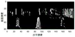
但是,现有视觉相机系统在准确区别路面标记和物体方面存在很大的麻烦。以交通锥和路面点线为例,两者在视觉上呈现出肉眼可见的不同,但采用车辆上的视觉相机系统拍摄的相机图像却几乎相同。举例而言,图1(a)和图1(b)是分别示出路面点线的原始图像及经视觉相机系统处理后的差分图像的示图,图1(c)和图1(d)是分别示出交通锥的原始图像及经视觉相机系统处理后的差分图像的示图,对应于图1(a)和图1(b)的,易知点线标记和交通锥在视觉上明显不同,而在差分图像中却是相似的。这是使用单目摄像头的视觉相机系统的固有问题,使得单目摄像头识别路面标记变得困难。However, existing vision camera systems have significant trouble accurately distinguishing between pavement markings and objects. Take the example of traffic cones and pavement point lines, which appear visually different to the naked eye, but the camera image captured by the vision camera system on the vehicle is almost the same. For example, Fig. 1(a) and Fig. 1(b) are diagrams respectively showing the original image of road surface points and lines and the difference image processed by the visual camera system, and Fig. 1(c) and Fig. 1(d) is a diagram showing the original image of traffic cones and the difference image processed by the visual camera system, corresponding to Figure 1(a) and Figure 1(b), it is easy to know that the dotted line marks and traffic cones are visually obvious different, but similar in the difference image. This is an inherent problem with vision camera systems using monocular cameras, making it difficult for monocular cameras to recognize pavement markings.
对此,现有技术中提出了多种方法来提升视觉相机系统区分路面标记和立方体物体的能力,而主要包括以下两种方法:In this regard, a variety of methods have been proposed in the prior art to improve the ability of the visual camera system to distinguish between road markings and cubic objects, and mainly include the following two methods:
1)采用至少具有两个相机的立体相机来区分路面标记和物体。该方案一方面需要至少两个相机,另一方面还对两个相机的距离设置有严格要求,例如在两个相机之间的距离设置为小于350mm时能勉强区分开前方的路面标记的物体,但此时该立体相机的测距范围限制在于小于70m的范围。1) A stereo camera with at least two cameras is employed to distinguish between pavement markings and objects. On the one hand, this solution requires at least two cameras, and on the other hand, it also has strict requirements on the distance between the two cameras. For example, when the distance between the two cameras is set to less than 350mm, it can barely distinguish the objects marked on the road ahead. But at this time, the ranging range of the stereo camera is limited to a range less than 70m.
2)使用获取多个图像的时间序列来区分路面标记和物体,但这需要不同距离的多个图像。2) Differentiate between pavement markings and objects using a time series of acquired multiple images, but this requires multiple images at different distances.
因此,目前没有有效的方法来通过使用单目摄像头的视觉相机系统中准确识别路面标记。Therefore, there is currently no effective way to accurately recognize pavement markings in a vision camera system using a monocular camera.
发明内容Contents of the invention
有鉴于此,本发明旨在提出一种用于识别路面标记的方法,以实现基于单目摄像头的图像准确识别路面目标。In view of this, the present invention aims to propose a method for recognizing road markings, so as to realize accurate recognition of road targets based on images of a monocular camera.
为达到上述目的,本发明的技术方案是这样实现的:In order to achieve the above object, technical solution of the present invention is achieved in that way:
一种用于识别路面标记的方法,包括:获取车辆上的单目摄像头所拍摄的原始图像;在所述原始图像中确定物体所在的中间区域以及位于该中间区域两侧的左区域和右区域;获取所述原始图像在所述左区域、所述右区域及所述中间区域的沿垂直方向的图像强度分布;以及通过比较所述左区域或所述右区域相对于所述中间区域的图像强度来确定所述物体是否为路面标记。A method for identifying road markings, comprising: acquiring an original image taken by a monocular camera on a vehicle; determining a middle area where an object is located and left and right areas located on both sides of the middle area in the original image ; Obtain the image intensity distribution of the original image in the left area, the right area and the middle area along the vertical direction; and by comparing the images of the left area or the right area with respect to the middle area Intensity to determine if the object is a pavement marking.
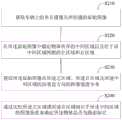
进一步的,在所述获取车辆上的单目摄像头所拍摄的原始图像之后,所述方法还包括:对所述原始图像进行图像预处理以获得对应的差分图像;获取所述差分图像中的边缘点;根据边缘点连续性对所述边缘点进行分组,并根据得到的各个边缘点组来估计所述物体的边缘线;在所述边缘线包括的组的数量大于预设的组阈值且其中的每一组中的边缘点数量小于预设的点阈值时,确定所述物体为路面标记。Further, after the acquisition of the original image captured by the monocular camera on the vehicle, the method further includes: performing image preprocessing on the original image to obtain a corresponding differential image; acquiring the edge in the differential image point; group the edge points according to the edge point continuity, and estimate the edge line of the object according to the obtained edge point groups; the number of groups included in the edge line is greater than the preset group threshold and wherein When the number of edge points in each group is less than a preset point threshold, it is determined that the object is a road marker.
进一步的,在所述原始图像中确定物体所在的中间区域以及位于该中间区域两侧的左区域和右区域包括:对所述原始图像进行图像预处理以获得对应的差分图像;获取所述差分图像中的边缘点;根据边缘点连续性对所述边缘点进行分组,以得到若干边缘点组;设置所述中间区域包括所述差分图像中的边缘点组;以及在所述中间区域的左侧和右侧分别设置所述左区域和所述右区域。Further, determining the middle area where the object is located and the left area and the right area located on both sides of the middle area in the original image includes: performing image preprocessing on the original image to obtain a corresponding difference image; obtaining the difference edge points in the image; group the edge points according to the edge point continuity to obtain several edge point groups; set the middle area to include the edge point groups in the difference image; and on the left side of the middle area The left area and the right area are respectively set on the side and the right side.
进一步的,所述通过比较所述左区域或所述右区域相对于所述中间区域的图像强度来确定所述物体是否为路面标记包括:计算第一强度平均值,其中所述第一强度平均值为所述左区域或所述右区域中的图像强度平均值;计算第二强度平均值,其中所述第二强度平均值为所述中间区域中的图像强度分布的峰值或谷值的图像强度平均值;以及若所述第一强度平均值和所述第二强度平均值的差值小于预设平均值阈值,则确定所述物体为路面标记;其中,所述预设平均值阈值被配置为小于所述峰值的图像强度平均值和所述谷值的图像强度平均值之间的差值。Further, the determining whether the object is a pavement marking by comparing the image intensity of the left region or the right region with respect to the middle region includes: calculating a first intensity average value, wherein the first intensity average value is the image intensity average value in the left region or the right region; calculate a second intensity average value, wherein the second intensity average value is an image of the peak or valley value of the image intensity distribution in the middle region an intensity average value; and if the difference between the first intensity average value and the second intensity average value is less than a preset average value threshold, then it is determined that the object is a pavement marking; wherein the preset average value threshold is determined by configured to be less than the difference between the image intensity average value of the peak and the image intensity average value of the valley value.
进一步的,在所述通过比较所述左区域或所述右区域相对于所述中间区域的图像强度来确定所述物体是否为路面标记之后,所述方法还包括:计算第一强度标准差,其中所述第一强度标准差为所述左区域或所述右区域中的图像强度标准差;计算第二强度标准差,其中所述第二强度标准差为所述中间区域中的图像强度分布的峰值或谷值的图像强度标准差;以及若所述第一强度标准差和所述第二强度标准差的差值小于预设标准差阈值且所述峰值和所述谷值的平均图像强度之间的差值大于所述第一强度标准差,则确定所述物体为路面标记。Further, after determining whether the object is a pavement marking by comparing the image intensity of the left region or the right region with respect to the middle region, the method further includes: calculating a first intensity standard deviation, Wherein the first intensity standard deviation is the image intensity standard deviation in the left region or the right region; calculate the second intensity standard deviation, wherein the second intensity standard deviation is the image intensity distribution in the middle region The image intensity standard deviation of the peak or valley; and if the difference between the first intensity standard deviation and the second intensity standard deviation is less than a preset standard deviation threshold and the average image intensity of the peak and the valley If the difference between them is greater than the first intensity standard deviation, then it is determined that the object is a pavement marking.
进一步的,在所述获取所述原始图像在所述左区域、所述右区域及所述中间区域的沿垂直方向的图像强度分布之后,以及在所述通过比较所述左区域或所述右区域相对于所述中间区域的图像强度来确定所述物体是否为路面标记之前,所述方法还包括:对所述左区域和所述右区域进行线性回归处理,以得到各自对应的线性回归线;根据所述左区域和所述右区域各自对应的线性回归线,计算所述左区域和所述右区域的平均线性回归线;以及根据所述平均线性回归线补偿所述原始图像在所述左区域、所述右区域及所述中间区域的沿垂直方向的图像强度分布。Further, after acquiring the image intensity distribution of the original image along the vertical direction in the left region, the right region and the middle region, and after comparing the left region or the right Before determining whether the object is a pavement marking with respect to the image intensity of the middle region, the method further includes: performing linear regression processing on the left region and the right region to obtain respective corresponding linear regression lines; According to the respective linear regression lines corresponding to the left region and the right region, calculate the average linear regression line of the left region and the right region; and compensate the original image in the left region, the right region according to the average linear regression line Image intensity distribution along the vertical direction of the right region and the middle region.
相对于现有技术,本发明所述的用于识别路面标记的方法可以基于单目相机的单帧图像区分出路面标记和立方体物体,从而达到准确识别路面标记的目的。Compared with the prior art, the method for recognizing road markings described in the present invention can distinguish road markings and cubic objects based on a single frame image of a monocular camera, thereby achieving the purpose of accurately recognizing road markings.
本发明的另一目的在于提出一种用于识别路面标记的装置,以实现基于单目摄像头的图像准确识别路面目标。Another object of the present invention is to provide a device for recognizing road markings, so as to realize accurate recognition of road targets based on images from a monocular camera.
为达到上述目的,本发明的技术方案是这样实现的:In order to achieve the above object, technical solution of the present invention is achieved in that way:
一种用于识别路面标记的装置,包括:图像获取模块,用于获取车辆上的单目摄像头所拍摄的原始图像;区域确定模块,用于在所述原始图像中确定物体所在的中间区域以及位于该中间区域两侧的左区域和右区域;强度获取模块,用于获取所述原始图像在所述左区域、所述右区域及所述中间区域的沿垂直方向的图像强度分布;以及第一识别模块,用于通过比较所述左区域或所述右区域相对于所述中间区域的图像强度来确定所述物体是否为路面标记。A device for identifying road markings, comprising: an image acquisition module, configured to acquire an original image taken by a monocular camera on a vehicle; an area determination module, configured to determine the middle area where an object is located in the original image and The left area and the right area located on both sides of the middle area; an intensity acquisition module, configured to acquire the image intensity distribution of the original image along the vertical direction in the left area, the right area, and the middle area; and the first A recognition module for determining whether the object is a pavement marking by comparing the image intensity of the left area or the right area with respect to the middle area.
进一步的,所述装置还包括第二识别模块,被配置为执行:对所述原始图像进行图像预处理以获得对应的差分图像;获取所述差分图像中的边缘点;根据边缘点连续性对所述边缘点进行分组,并根据得到的各个边缘点组来估计所述物体的边缘线;以及在所述边缘线包括的组的数量大于预设的组阈值且其中的每一组中的边缘点数量小于预设的点阈值时,确定所述物体为路面标记。Further, the device further includes a second recognition module configured to execute: performing image preprocessing on the original image to obtain a corresponding difference image; acquiring edge points in the difference image; The edge points are grouped, and the edge line of the object is estimated according to each obtained edge point group; and the number of groups included in the edge line is greater than a preset group threshold and the edge in each group wherein When the number of points is less than the preset point threshold, it is determined that the object is a road surface mark.
进一步的,所述区域确定模块包括:图像处理子模块,用于对所述原始图像进行图像预处理以获得对应的差分图像,并获取所述差分图像中的边缘点,以及根据边缘点连续性对所述边缘点进行分组,以得到若干边缘点组;区域确定子模块,用于设置所述中间区域包括所述差分图像中的边缘点组,并在所述中间区域的左侧和右侧分别设置所述左区域和所述右区域。进一步的,所述第一识别模块包括:第一计算子模块,用于计算第一强度平均值,其中所述第一强度平均值为所述左区域或所述右区域中的图像强度平均值;第二计算子模块,用于计算第二强度平均值,其中所述第二强度平均值为所述中间区域中的图像强度分布的峰值或谷值的图像强度平均值;以及第一确定子模块,用于在所述第一强度平均值和所述第二强度平均值的差值小于预设平均值阈值时,确定所述物体为路面标记,其中,所述预设平均值阈值被配置为小于所述峰值的图像强度平均值和所述谷值的图像强度平均值之间的差值。Further, the area determination module includes: an image processing sub-module, configured to perform image preprocessing on the original image to obtain a corresponding difference image, obtain edge points in the difference image, and The edge points are grouped to obtain several edge point groups; the area determination submodule is used to set the middle area to include the edge point groups in the difference image, and on the left and right sides of the middle area The left area and the right area are respectively set. Further, the first identification module includes: a first calculation submodule, configured to calculate a first average intensity value, wherein the first average intensity value is the average image intensity value in the left region or the right region ; The second calculation submodule is used to calculate the second intensity average value, wherein the second intensity average value is the image intensity average value of the peak or valley value of the image intensity distribution in the middle region; and the first determiner A module configured to determine that the object is a pavement mark when the difference between the first average intensity value and the second intensity average value is less than a preset average value threshold, wherein the preset average value threshold is configured is the difference between the image intensity average value less than the peak and the image intensity average value of the valley value.
进一步的,所述第一识别模块还包括:第三计算子模块,用于计算第一强度标准差,其中所述第一强度标准差为所述左区域或所述右区域中的图像强度标准差;第四计算子模块,用于计算第二强度标准差,其中所述第二强度标准差为所述中间区域中的图像强度分布的峰值或谷值的图像强度标准差;以及第二确定子模块,用于在所述第一强度标准差和所述第二强度标准差的差值小于预设标准差阈值且所述峰值和所述谷值的平均图像强度之间的差值大于所述第一强度标准差时,确定所述物体为路面标记。Further, the first identification module further includes: a third calculation submodule, configured to calculate a first intensity standard deviation, wherein the first intensity standard deviation is an image intensity standard in the left region or the right region difference; the fourth calculation submodule is used to calculate the second intensity standard deviation, wherein the second intensity standard deviation is the image intensity standard deviation of the peak or valley of the image intensity distribution in the middle region; and the second determination A submodule, configured to be configured when the difference between the first intensity standard deviation and the second intensity standard deviation is less than a preset standard deviation threshold and the difference between the average image intensities of the peak value and the valley value is greater than the specified When the first intensity standard deviation is determined, the object is determined to be a pavement marking.
进一步的,所述装置还包括强度补偿模块,被配置为执行:对所述左区域和所述右区域进行线性回归处理,以得到各自对应的线性回归线;根据所述左区域和所述右区域各自对应的线性回归线,计算所述左区域和所述右区域的平均线性回归线;以及根据所述平均线性回归线补偿所述原始图像在所述左区域、所述右区域及所述中间区域的沿垂直方向的图像强度分布。Further, the device further includes an intensity compensation module configured to: perform linear regression processing on the left area and the right area to obtain respective corresponding linear regression lines; calculating the average linear regression line of the left region and the right region for each corresponding linear regression line; and compensating the edge of the original image in the left region, the right region and the middle region according to the average linear regression line Image intensity distribution in the vertical direction.
所述用于识别路面标记的装置与上述用于识别路面标记的方法相对于现有技术所具有的优势相同,在此不再赘述。The device for identifying road markings has the same advantages as the above-mentioned method for identifying road markings over the prior art, and will not be repeated here.
本发明的另一目的在于提出一种单目摄像头,以实现基于单目摄像头的图像准确识别路面目标。Another object of the present invention is to provide a monocular camera to realize accurate recognition of road targets based on images of the monocular camera.
为达到上述目的,本发明的技术方案是这样实现的:In order to achieve the above object, technical solution of the present invention is achieved in that way:
一种单目摄像头,设置有上述的用于识别路面标记的装置。A monocular camera is provided with the above-mentioned device for recognizing road markings.
所述单目摄像头与上述用于识别路面标记的方法相对于现有技术所具有的优势相同,在此不再赘述。The advantages of the monocular camera and the above-mentioned method for identifying road markings are the same as those of the prior art, and will not be repeated here.
本发明的另一目的在于提出一种机器可读存储介质,以实现基于单目摄像头的图像准确识别路面目标。Another object of the present invention is to provide a machine-readable storage medium to realize accurate recognition of road targets based on images from a monocular camera.
为达到上述目的,本发明的技术方案是这样实现的:In order to achieve the above object, technical solution of the present invention is achieved in that way:
一种机器可读存储介质,该机器可读存储介质上存储有指令,该指令用于使得机器执行上述的用于识别路面标记的方法。A machine-readable storage medium, where instructions are stored on the machine-readable storage medium, and the instructions are used to make a machine execute the above-mentioned method for identifying road markings.
所述机器可读存储介质与上述用于识别路面标记的方法相对于现有技术所具有的优势相同,在此不再赘述。The machine-readable storage medium has the same advantages as the above-mentioned method for identifying road markings over the prior art, and will not be repeated here.
本发明的其它特征和优点将在随后的具体实施方式部分予以详细说明。Other features and advantages of the present invention will be described in detail in the detailed description that follows.
附图说明Description of drawings
构成本发明的一部分的附图用来提供对本发明的进一步理解,本发明的示意性实施方式及其说明用于解释本发明,并不构成对本发明的不当限定。The drawings constituting a part of the present invention are used to provide a further understanding of the present invention, and the schematic implementations and descriptions of the present invention are used to explain the present invention, and do not constitute an improper limitation of the present invention.
在附图中:In the attached picture:
图1(a)和图1(b)是分别示出路面点线的原始图像及经视觉相机系统处理的差分图像的示图;Fig. 1 (a) and Fig. 1 (b) are the diagrams showing respectively the original image of the road point line and the differential image processed by the visual camera system;
图1(c)和图1(d)是分别示出交通锥的原始图像及经视觉相机系统处理的差分图像的示图;Figure 1(c) and Figure 1(d) are diagrams showing the original image of the traffic cone and the difference image processed by the visual camera system, respectively;
图2是本发明实施例一的用于识别路面标记的方法的流程示意图;FIG. 2 is a schematic flowchart of a method for identifying road markings according to Embodiment 1 of the present invention;
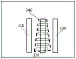
图3(a)是本发明实施例中示出针对图1(a)的点线标记定义的区域的示意图;Fig. 3(a) is a schematic diagram showing the area defined by the dotted line mark in Fig. 1(a) in an embodiment of the present invention;
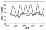
图3(b)是本发明实施例中初始获得的左区域、所述右区域及所述中间区域对应的图像强度分布示意图;Fig. 3(b) is a schematic diagram of the image intensity distribution corresponding to the left region, the right region and the middle region initially obtained in the embodiment of the present invention;
图3(c)是采用图4的方法对图3(b)的图像强度分布进行补偿后的新的图像强度分布的示意图;Fig. 3 (c) is a schematic diagram of a new image intensity distribution after compensating the image intensity distribution of Fig. 3 (b) by using the method of Fig. 4;
图3(d)是从图3(c)的图像强度分布图像中拾取峰值和谷值的示意图;Figure 3(d) is a schematic diagram of picking peaks and valleys from the image intensity distribution image of Figure 3(c);
图3(e)是对图3(a)的场景进行目标检测的结果示意图;Figure 3(e) is a schematic diagram of the result of target detection for the scene in Figure 3(a);
图4是本发明实施例中利用线性回归补偿中间区域的图像强度的线性偏移的方法的流程示意图;Fig. 4 is a schematic flowchart of a method for compensating linear offset of image intensity in the middle region by using linear regression in an embodiment of the present invention;
图5是示出基于三个区域的图像强度来确定对应物体是否为路面标记的流程示意图;Fig. 5 is a schematic flow diagram illustrating determining whether a corresponding object is a pavement marking based on image intensities of three regions;
图6是本发明实施例二的用于识别路面标记的方法的流程示意图;6 is a schematic flowchart of a method for identifying road markings according to Embodiment 2 of the present invention;
图7是结合实施例一与实施例二的方法的示例的执行步骤示意图;Fig. 7 is a schematic diagram of execution steps of an example of combining the methods of Embodiment 1 and Embodiment 2;
图8是本发明实施例三的路面标记识别方法的流程示意图;FIG. 8 is a schematic flow chart of a road marking recognition method according to Embodiment 3 of the present invention;
图9是本发明实施例中进行边缘点分组的示意图;以及Fig. 9 is a schematic diagram of grouping edge points in an embodiment of the present invention; and
图10是本发明实施例四的用于识别路面标记的装置的结构示意图。Fig. 10 is a schematic structural diagram of a device for recognizing road markings according to Embodiment 4 of the present invention.
附图标记说明:Explanation of reference signs:
310、左区域;320、中间区域;330、右区域;340、待估计物体;310, the left area; 320, the middle area; 330, the right area; 340, the object to be estimated;
1010、图像获取模块;1020、强度获取模块;1030、第一识别模块。1010. An image acquisition module; 1020. An intensity acquisition module; 1030. A first identification module.
具体实施方式Detailed ways
需要说明的是,在不冲突的情况下,本发明中的实施方式及实施方式中的特征可以相互组合。It should be noted that, in the case of no conflict, the embodiments and features in the embodiments of the present invention can be combined with each other.
需说明的是,在本发明实施例中,涉及识别物体时所针对的物体既包括路面标记,也包括立方体物体,即对应于某一物体,在应用本发明实施例的方案进行识别之前,无法确定其为路面标记还是立方体物体。其中,所述路面标记包括点线等,所述立方体物体包括交通锥等。It should be noted that, in the embodiment of the present invention, when it comes to identifying objects, the objects targeted include both road markings and cubic objects, that is, corresponding to a certain object, before the solution of the embodiment of the present invention is applied for recognition, it cannot Determine if it is a pavement marker or a cube object. Wherein, the road surface markings include dotted lines and the like, and the cubic objects include traffic cones and the like.
下面将参考附图并结合实施方式来详细说明本发明。The present invention will be described in detail below with reference to the drawings and in combination with embodiments.
实施例一Embodiment one
图2是本发明实施例一的用于识别路面标记的方法的流程示意图。如图2所示,该用于识别路面标记的方法可以包括以下步骤:Fig. 2 is a schematic flowchart of a method for identifying road markings according to Embodiment 1 of the present invention. As shown in Figure 2, the method for identifying pavement markings may include the following steps:
步骤S210,获取车辆上的单目摄像头所拍摄的原始图像。Step S210, acquiring the original image captured by the monocular camera on the vehicle.
步骤S220,在所述原始图像中确定物体所在的中间区域以及位于该中间区域两侧的左区域和右区域。Step S220, determining the middle area where the object is located and the left and right areas located on both sides of the middle area in the original image.
在优选的实施例中,该步骤S220进一步包括:对所述原始图像进行图像预处理以获得对应的差分图像;获取所述差分图像中的边缘点;根据边缘点连续性对所述边缘点进行分组,以得到若干边缘点组;设置所述中间区域包括所述差分图像中的边缘点组;以及在所述中间区域的左侧和右侧分别设置所述左区域和所述右区域。In a preferred embodiment, the step S220 further includes: performing image preprocessing on the original image to obtain a corresponding difference image; obtaining edge points in the difference image; grouping to obtain several edge point groups; setting the middle area to include edge point groups in the difference image; and setting the left area and the right area on the left and right sides of the middle area, respectively.
其中将单目摄像头的原始图像转变为差分图像的方法在本领域是常规的,故不再对其细节进行描述。本发明实施例中,所述差分图像可以为二值化差分图像或三元差分图像。另外,对差分图像应用常规边缘处理技术,从而获得相应的边缘点,并进而分组成为边缘点组。The method of converting the original image of the monocular camera into the differential image is conventional in the art, so its details will not be described. In the embodiment of the present invention, the difference image may be a binary difference image or a ternary difference image. In addition, conventional edge processing techniques are applied to the differential image to obtain corresponding edge points, which are then grouped into edge point groups.
据此,使得所述原始图像设置有物体所在的中间区域以及位于该中间区域两侧的左区域和右区域,以图1(a)所示的点线标记为例,图3(a)是示出针对图1(a)的点线定义的区域的示意图,其中,中间区域320位于待估计物体340处,而左区域310和右区域330位于待估计物体340的两侧。Accordingly, the original image is provided with the middle area where the object is located and the left area and the right area located on both sides of the middle area, taking the dotted line mark shown in Figure 1 (a) as an example, Figure 3 (a) is A schematic diagram showing regions defined by dotted lines in FIG. 1( a ), wherein the
步骤S230,获取所述原始图像在所述左区域、所述右区域及所述中间区域的沿垂直方向的图像强度分布。Step S230, acquiring the image intensity distribution along the vertical direction of the original image in the left region, the right region and the middle region.
其中,图像强度是指每一像素的强度,对应的图像强度分布可从单目摄像头直接获得。在此,图3(b)是初始获得的所述左区域、所述右区域及所述中间区域对应的图像强度分布示意图,如该图3(b)所示,中间区域320因包含物体,故而呈现的图像强度变化很大,而左区域310和右区域320则呈现相对较为平缓的图像强度。Wherein, the image intensity refers to the intensity of each pixel, and the corresponding image intensity distribution can be obtained directly from the monocular camera. Here, FIG. 3(b) is a schematic diagram of the initially obtained image intensity distribution corresponding to the left region, the right region, and the middle region. As shown in FIG. 3(b), the
另外,如图3(b)所示,中间区域320的图像强度曲线存在线性偏移的问题,其所有图像强度值都沿水平轴线性减小。对此,为保证后续识别路面标记的准确度,应考虑消除中间区域320的图像强度的线性偏移。如此,在本发明优选的实施例中,提出了利用线性回归补偿中间区域320的图像强度的线性偏移的方法。图4是该利用线性回归补偿中间区域320的图像强度的线性偏移的方法的流程示意图,如图4所示,该方法包括以下步骤:In addition, as shown in FIG. 3( b ), the image intensity curve of the
步骤S410,对所述左区域和所述右区域进行线性回归处理,以得到各自对应的线性回归线。Step S410, performing linear regression processing on the left area and the right area to obtain respective linear regression lines.
步骤S420,根据所述左区域和所述右区域各自对应的线性回归线,计算所述左区域和所述右区域的平均线性回归线。Step S420, calculating an average linear regression line of the left region and the right region according to the respective linear regression lines of the left region and the right region.
步骤S430,根据所述平均线性回归线补偿所述原始图像在所述左区域、所述右区域及所述中间区域的沿垂直方向的图像强度分布。Step S430 , compensating the image intensity distribution along the vertical direction of the original image in the left region, the right region and the middle region according to the average linear regression line.
图3(c)是采用图4的方法对图3(b)的图像强度分布进行补偿后的新的图像强度分布的示意图,如图3(c)所示,补偿后的中间区域320的图像强度不再存在线性偏差。Fig. 3(c) is a schematic diagram of a new image intensity distribution after compensating the image intensity distribution of Fig. 3(b) by using the method of Fig. 4, as shown in Fig. 3(c), the image of the
步骤S240,通过比较所述左区域或所述右区域相对于所述中间区域的图像强度来确定所述物体是否为路面标记。Step S240, by comparing the image intensity of the left area or the right area with that of the middle area to determine whether the object is a pavement marking.
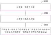
其中,对于路面标记,其相对于立方体物体(如交通锥),图像强度的峰值或谷值会更为接近于两侧的图像部分的图像强度,故而可通过比较所述左区域或所述右区域相对于所述中间区域的图像强度来确定原始图像中的物体是否为路面标记。在优选的实施例中,图5是示出基于三个区域的图像强度来确定对应物体是否为路面标记的流程示意图,如图5所示,可包括以下步骤:Wherein, for road surface markings, compared to cubic objects (such as traffic cones), the peak value or valley value of the image intensity will be closer to the image intensity of the image parts on both sides, so by comparing the left area or the right The image intensity of the area relative to the intermediate area is used to determine whether the object in the original image is a pavement marking. In a preferred embodiment, FIG. 5 is a schematic flow diagram illustrating determining whether the corresponding object is a pavement marking based on image intensities of three regions. As shown in FIG. 5 , the following steps may be included:
步骤S510,计算第一强度平均值,其中所述第一强度平均值为所述左区域或所述右区域中的图像强度平均值。Step S510, calculating a first average intensity, wherein the first average intensity is an average image intensity in the left region or the right region.
举例而言,设左区域和右区域的图像强度平均值分别为ave_1和ave_2,其通过对左区域和右区域的图像像素进行常规的数理统计分析就可以得到。For example, suppose the average values of the image intensities of the left region and the right region are respectively ave_1 and ave_2, which can be obtained by performing conventional mathematical statistical analysis on the image pixels of the left region and the right region.
步骤S520,计算第二强度平均值,其中所述第二强度平均值为所述中间区域中的图像强度分布的峰值或谷值的图像强度平均值。Step S520, calculating a second average intensity value, wherein the second average intensity value is the average image intensity value of the peak or valley of the image intensity distribution in the middle region.
其中,图3(d)是从图3(c)的图像强度分布图像中拾取峰值和谷值的示意图,参考图3(d),进一步对拾取的峰值和谷值进行关于平均值的数理统计分析,得到对应的峰值或谷值的图像强度平均值,举例而言,可分别设置为ave2_h和ave2_b。Among them, Figure 3(d) is a schematic diagram of picking peaks and valleys from the image intensity distribution image in Figure 3(c), referring to Figure 3(d), further performing mathematical statistics on the average value of the picked peaks and valleys Analyze to obtain the average image intensity of the corresponding peak or valley, for example, can be set as ave2_h and ave2_b respectively.
步骤S530,若所述第一强度平均值和所述第二强度平均值的差值小于预设平均值阈值,则确定所述物体为路面标记。Step S530, if the difference between the first average intensity value and the second average intensity value is smaller than a preset average value threshold, then determine that the object is a road surface mark.
在此,预设平均值阈值一般设置为较小的值,以使得所述第一强度平均值和所述第二强度平均值的差值足够小。优选地,预设平均值阈值被配置为远小于所述峰值的图像强度平均值和所述谷值的图像强度平均值之间的差值,据此表明中间区域320的坡峰和坡谷的像素与左区域330或右区域330更为接近,从而物体为路面标记的可能性更高。Here, the preset average value threshold is generally set to a small value, so that the difference between the first average intensity value and the second average intensity value is small enough. Preferably, the preset average value threshold is configured to be much smaller than the difference between the image intensity average value of the peak value and the image intensity average value of the valley value, thereby indicating the difference between the peak and valley of the
在优选的实施例中,预设平均值阈值可以为峰值和谷值的图像强度平均值的差值的四分之一,以此为例,步骤S530的判定过程可表达如下:In a preferred embodiment, the preset average value threshold may be a quarter of the difference between the peak and valley image intensity average values. Taking this as an example, the determination process of step S530 may be expressed as follows:
若abs(ave2_h-ave_1)<abs(ave2_h-ave2_b)/4,则判定为点线,其中波峰在左侧;(1)If abs(ave2_h-ave_1)<abs(ave2_h-ave2_b)/4, it is judged as a dotted line, where the peak is on the left; (1)
若abs(ave2_b-ave_1)<abs(ave2_h-ave2_b)/4,则判定为点线,其中波谷在左侧;(2)If abs(ave2_b-ave_1)<abs(ave2_h-ave2_b)/4, it is judged as a dotted line, where the trough is on the left; (2)
式中,可用ave_3代替ave_1。In the formula, ave_3 can be used instead of ave_1.
参考图3(d),对应数值为[ave_1,ave_3]=[94.5,93.9],[ave2_b]=94.5,[ave2_h]=120.7,可知满足上面的式(2),所识别的物体为波谷在左侧的点线。据此,图3(e)是对图3(a)的场景进行目标检测的结果示意图,可知分析区域内的物体为点线,因此实质上未识别到属于立方体物体的目标。Referring to Figure 3(d), the corresponding values are [ave_1, ave_3] = [94.5, 93.9], [ave2_b] = 94.5, [ave2_h] = 120.7, it can be seen that the above formula (2) is satisfied, and the identified object is a trough in Dotted line on the left. Accordingly, Fig. 3(e) is a schematic diagram of the result of object detection for the scene in Fig. 3(a), and it can be seen that the objects in the analysis area are dotted lines, so substantially no objects belonging to cubic objects are recognized.
返回至图1(a)-图1(d),采用本发明实施例的方法可以基于单目相机的单帧图像准确识别待估计物体是否为路面标记,且通过图3(a)-图3(有)证实了本发明实施例的方法在应用于实际图像数据时,运行良好。Returning to Figure 1(a)-Figure 1(d), the method of the embodiment of the present invention can accurately identify whether the object to be estimated is a road mark based on a single frame image of a monocular camera, and through Figure 3(a)-Figure 3 (Yes) It is verified that the method of the embodiment of the present invention works well when applied to actual image data.
实施例二Embodiment two
本发明实施例一的方法能够在大多数场景中准确识别出路面标记,但在一些非常复杂的场景中,例如涉及多种类型的点线、立方体物体时,本发明实施例一的方法的识别可靠性会有所降低。其中,及重影(ghost)物体是最为典型的一种路面标记,其可以是点线,但不是真实存在的立方体物体,因为其仅仅能在路面进行绘制。对此,本发明实施例二在实施例一的基础上,引入更多的参数来更好识别路面标记。The method of Embodiment 1 of the present invention can accurately identify road markings in most scenes, but in some very complex scenes, for example, when involving multiple types of point lines and cubic objects, the recognition of the method of Embodiment 1 of the present invention Reliability will be reduced. Among them, a ghost object is the most typical road marking, which can be a dotted line, but not a real cube object, because it can only be drawn on the road. In this regard, on the basis of the first embodiment, the second embodiment of the present invention introduces more parameters to better identify road markings.
图6是本发明实施例二的用于识别路面标记的方法的流程示意图,该方法在实施例一的方法的基础上,可进一步包括以下步骤:Fig. 6 is a schematic flow chart of a method for identifying road markings according to Embodiment 2 of the present invention. On the basis of the method in Embodiment 1, the method may further include the following steps:
步骤S610,计算第一强度标准差。Step S610, calculating the first intensity standard deviation.
其中,所述第一强度标准差为所述左区域或所述右区域中的图像强度标准差。Wherein, the first intensity standard deviation is the image intensity standard deviation in the left region or the right region.
举例而言,设左区域和右区域的图像强度标准差分别为std_1和std_3,其中,标准差与平均值都是数理统计中的常用参数,在此可通过对左区域和右区域的图像像素进行常规的数理统计分析得到对应的标准差。For example, let the image intensity standard deviations of the left area and the right area be std_1 and std_3 respectively, where the standard deviation and the average value are commonly used parameters in mathematical statistics. Here, the image pixels of the left area and the right area can be The corresponding standard deviation was obtained by performing conventional mathematical statistical analysis.
步骤S620,计算第二强度标准差。Step S620, calculating the second intensity standard deviation.
其中,所述第二强度标准差为所述中间区域中的图像强度分布的峰值或谷值的图像强度标准差。Wherein, the second intensity standard deviation is the image intensity standard deviation of the peak or valley of the image intensity distribution in the middle region.
参考步骤S520中确定峰值或谷值的图像强度平均值的方案,举例而言,可分别设置峰值或谷值的图像强度标准差为std2_h和std2_b。Referring to the solution of determining the average value of the image intensity of the peak value or the valley value in step S520, for example, the standard deviation of the image intensity of the peak value or the valley value may be respectively set as std2_h and std2_b.
步骤S630,若所述第一强度标准差和所述第二强度标准差的差值小于预设标准差阈值且所述峰值和所述谷值的平均图像强度之间的差值大于所述第一强度标准差,则确定所述物体为路面标记。其中,所述峰值和所述谷值的平均图像强度之间的差值优选为远大于所述第一强度标准差。Step S630, if the difference between the first intensity standard deviation and the second intensity standard deviation is less than a preset standard deviation threshold and the difference between the average image intensities of the peak value and the valley value is greater than the first If the intensity standard deviation is greater than or equal to 1, the object is determined to be a pavement marking. Wherein, the difference between the average image intensities of the peak value and the valley value is preferably much larger than the first intensity standard deviation.
其中,预设标准差阈值可根据需要进行设定,优选设定为较小值,以便基于标准差,使中间区域320的坡峰和坡谷的像素与左区域310或右区域330更为接近,从而判断物体是否为路面标记的可靠性更高。Wherein, the preset standard deviation threshold can be set as required, preferably set to a smaller value, so that based on the standard deviation, the pixels of the peaks and valleys of the
在优选的实施例中,第一强度标准差std_1和std_3还可与中间区域对应的第二强度平均值ave2_h、ave2_b相结合以判断是否结束路面标记的识别,举例而言,对应于上述的式(1)和式(2),判定过程可进一步表达为如下:In a preferred embodiment, the first intensity standard deviations std_1 and std_3 can also be combined with the second intensity average values ave2_h and ave2_b corresponding to the middle region to determine whether to end the identification of road markings, for example, corresponding to the above formula (1) and formula (2), the judgment process can be further expressed as follows:
若abs(ave2_h-ave2_b)/4<std_1或者abs(ave2_h-ave2_b)/4<std_1,则结束识别;(3)If abs(ave2_h-ave2_b)/4<std_1 or abs(ave2_h-ave2_b)/4<std_1, end the recognition; (3)
式中,可使用std_3代替std_1。In the formula, std_3 can be used instead of std_1.
结合实施例一的内容,本发明实施例二在其基础上增加了利用图像强度标准差进一步判断是否识别到路面标记,使得本发明实施例的方法能够适用于更为复杂的道路场景,提高了路面标记识别的准确度。Combining the content of the first embodiment, the second embodiment of the present invention adds the use of the image intensity standard deviation to further judge whether the road surface marking is recognized, so that the method of the embodiment of the present invention can be applied to more complex road scenes, improving the Accuracy of pavement marking recognition.
综合上文,以点线判断为例,下面给出融合了实施例一和实施例二方法的示例的具体执行步骤,如图7所示,具体包括以下步骤:Based on the above, taking the point-line judgment as an example, the specific execution steps of the example that combines the methods of Embodiment 1 and Embodiment 2 are given below, as shown in Figure 7, which specifically includes the following steps:
步骤S710,选中原始图像中预期要进行点线识别的物体。Step S710, selecting an object in the original image that is expected to be recognized by points and lines.
如图1(a)所示,用圆圈确定分析区域,该分析区域中包括了预期进行识别的待估计物体。As shown in FIG. 1( a ), the analysis area is determined by a circle, and the object to be estimated that is expected to be identified is included in the analysis area.
步骤S720,定义三个区域。Step S720, define three areas.
如图3(a)所示,定义左区域310、中间区域320和右区域330。As shown in FIG. 3( a ), a
步骤S730,获得各区域的图像强度分布。Step S730, obtaining the image intensity distribution of each region.
如图3(b)所示,绘制各区域的图像强度分布图。As shown in Figure 3(b), the image intensity distribution map of each region is drawn.
步骤S740,对左区域和右区域进行线性回归处理,并得到的线性回归线补偿三个区域的图像强度分布。Step S740, performing linear regression processing on the left region and the right region, and obtaining the linear regression line to compensate the image intensity distribution of the three regions.
具体地,可参考上述的步骤S410-S430,获得如图3(c)所示的补偿后的图像强度分布图。Specifically, the above-mentioned steps S410-S430 may be referred to to obtain a compensated image intensity distribution diagram as shown in FIG. 3(c).
步骤S750,从补偿后的图像强度分布中拾取中间区域的峰值和谷值。Step S750, picking out peaks and valleys in the middle area from the compensated image intensity distribution.
如图3(d)所示,对中间区域的峰值和谷值进行了拾取。As shown in Fig. 3(d), peaks and valleys in the middle region are picked.
步骤S760,计算所拾取的峰值和谷值的平均值及标准差,即平均值ave2_h、ave2_b以及标准差std2_h和std2_b。Step S760, calculating the average value and standard deviation of the picked peak and valley values, ie the average values ave2_h, ave2_b and standard deviations std2_h and std2_b.
步骤S770,计算左区域和右区域的平均值和标准差,即平均值ave_1、ave_3以及标准差std_1、std_3。Step S770, calculating the average value and standard deviation of the left region and the right region, namely the average values ave_1, ave_3 and standard deviations std_1, std_3.
步骤S780,进行点线判断。Step S780, dot-line judgment.
具体地,判断上述的公式(1)-(3)是否成立,若式(3)成立,表明无法判断是否为点线,故结束判断;若式(1)和式(2)成立,则判定为点线,并结束判断。在通过公式(1)-(3)无法判断是否为点线的情况下,可进一步引入图像强度的标准差进行判断,例如通过以下公式进行判断:Specifically, judge whether the above-mentioned formulas (1)-(3) are true. If the formula (3) is true, it indicates that it is impossible to judge whether it is a dotted line, so the judgment ends; if the formulas (1) and (2) are true, then judge for the dotted line, and end the judgment. In the case where it is impossible to judge whether it is a dotted line through the formulas (1)-(3), the standard deviation of the image intensity can be further introduced for judgment, for example, the following formula can be used for judgment:
若abs(std2_h-std_1)<abs(std2_h-std2_b)/n,则判定为点线,其中波峰在左侧;(4)If abs(std2_h-std_1)<abs(std2_h-std2_b)/n, it is judged as a dotted line, where the peak is on the left; (4)
若abs(std2_b-std_1)<abs(std2_h-std2_b)/n,则判定为点线,其中波谷在左侧;(4)If abs(std2_b-std_1)<abs(std2_h-std2_b)/n, it is judged as a dotted line, where the trough is on the left; (4)
其中,可用std_3代替std_1,且n为正整数,例如n为4,以使得作为预设标准差阈值的abs(std2_h-std2_b)/n的值足够小。Wherein, std_3 can be used instead of std_1, and n is a positive integer, for example, n is 4, so that the value of abs(std2_h-std2_b)/n as the preset standard deviation threshold is small enough.
如此,相比于实施例一,通过增加标准差判断环节,可提高本发明实施例的用于识别路面标记的方法的应用性和可靠性。In this way, compared with the first embodiment, the applicability and reliability of the method for identifying road markings in the embodiment of the present invention can be improved by adding a standard deviation judgment link.
实施例三Embodiment three
在实施例一的基础上,本发明实施例三提供了另一种识别路面标记的方法,其可以单独执行,也可以与实施例一相配合以更全面地识别出路面标记。图8是本发明实施例三的路面标记识别方法的流程示意图,如图8所示,可以包括以下步骤:On the basis of the first embodiment, the third embodiment of the present invention provides another method for identifying road markings, which can be performed alone or in cooperation with the first embodiment to identify road markings more comprehensively. Fig. 8 is a schematic flowchart of a road surface marking recognition method according to Embodiment 3 of the present invention. As shown in Fig. 8, the following steps may be included:
步骤S810,对所述原始图像进行图像预处理以获得对应的差分图像。Step S810, performing image preprocessing on the original image to obtain a corresponding difference image.
步骤S820,获取所述差分图像中的边缘点。Step S820, acquiring edge points in the difference image.
步骤S830,根据边缘点连续性对所述边缘点进行分组,并根据得到的各个组来估计所述物体的边缘线。Step S830, grouping the edge points according to the continuity of the edge points, and estimating the edge line of the object according to each obtained group.
图9是本发明实施例中进行边缘点分组的示意图,其中形成的边缘组定义为连续边缘点的组合,且各些边缘组相互进行关联可估计出对应的边缘线。在此,以点线为例,可知点线的边缘点由许多边缘组组成,且每一边缘组有少量的边缘点。FIG. 9 is a schematic diagram of grouping edge points in an embodiment of the present invention, wherein the formed edge group is defined as a combination of continuous edge points, and the corresponding edge lines can be estimated by associating each edge group with each other. Here, taking the dotted line as an example, it can be seen that the edge points of the dotted line are composed of many edge groups, and each edge group has a small number of edge points.
步骤S840,在所述边缘线包括的组的数量大于预设的组阈值且其中的每一组中的边缘点数量小于预设的点阈值时,确定所述物体为路面标记。Step S840, when the number of groups included in the edge line is greater than a preset group threshold and the number of edge points in each group is smaller than a preset point threshold, determine that the object is a road marker.
举例而言,针对点线的特点,设所述组阈值和点阈值都为6,则对于满足以下两个条件的线段,可判定为不是点线:1)存在少于或等于6个组;2)组中边缘点数量大于或等于6。对应地,与之相反的线段则可判定为点线。需说明的是,每一组中边缘点尺寸可能不相同,优选采用最大边缘点进行判断。For example, for the characteristics of a dotted line, if both the group threshold and the point threshold are set to 6, then a line segment that satisfies the following two conditions can be determined not to be a dotted line: 1) there are less than or equal to 6 groups; 2) The number of edge points in the group is greater than or equal to 6. Correspondingly, the opposite line segment can be determined as a dotted line. It should be noted that the size of the edge points in each group may be different, and it is preferable to use the largest edge point for judgment.
该实施例三的方法在多数场景下运行良好,且相对于实施例一和实施例二的方法更加易于实现,从而在一些场景下可只采用实施例三的方法来进行路面标记识别。但是,当进行边缘组连接或某些边缘组丢弃时,这种方法将无法正常实现,从而本发明实施例进一步提出了实施例一和实施例二的方法,以保证能够在多种场景和工况下实现对路面标记的准确识别。The method of Embodiment 3 works well in most scenarios, and is easier to implement than the methods of Embodiment 1 and Embodiment 2. Therefore, in some scenarios, only the method of Embodiment 3 can be used for pavement marking recognition. However, when performing edge group connection or some edge group discarding, this method will not be able to be implemented normally, so the embodiment of the present invention further proposes the method of embodiment 1 and embodiment 2 to ensure that it can be used in various scenarios and work Accurate recognition of road markings under certain conditions.
实施例四Embodiment four
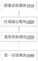
本发明实施例四与实施例一基于相同的发明思路,其提供了一种用于识别路面标记的装置。图10是本发明实施例四的用于识别路面标记的装置的结构示意图。如图10所示,该装置可以包括:图像获取模块1010,用于获取车辆上的单目摄像头所拍摄的原始图像;区域确定模块1020,用于在所述原始图像中确定物体所在的中间区域以及位于该中间区域两侧的左区域和右区域;强度获取模块1030,用于获取所述原始图像在所述左区域、所述右区域及所述中间区域的沿垂直方向的图像强度分布;以及第一识别模块1040,用于通过比较所述左区域或所述右区域相对于所述中间区域的图像强度来确定所述物体是否为路面标记。Embodiment 4 of the present invention is based on the same inventive idea as Embodiment 1, which provides a device for identifying road markings. Fig. 10 is a schematic structural diagram of a device for recognizing road markings according to Embodiment 4 of the present invention. As shown in Figure 10, the device may include: an image acquisition module 1010, configured to acquire the original image captured by the monocular camera on the vehicle; an area determination module 1020, configured to determine the middle area where the object is located in the original image and a left area and a right area located on both sides of the middle area; an intensity acquisition module 1030, configured to acquire the image intensity distribution of the original image along the vertical direction in the left area, the right area, and the middle area; And a first identification module 1040, configured to determine whether the object is a road surface mark by comparing the image intensity of the left area or the right area with that of the middle area.
在优选的实施例中,所述区域确定模块1020可以包括:图像处理子模块,用于对所述原始图像进行图像预处理以获得对应的差分图像,并获取所述差分图像中的边缘点,以及根据边缘点连续性对所述边缘点进行分组,以得到若干边缘点组;区域确定子模块,用于设置所述中间区域包括所述差分图像中的边缘点组,并在所述中间区域的左侧和右侧分别设置所述左区域和所述右区域。In a preferred embodiment, the area determination module 1020 may include: an image processing submodule, configured to perform image preprocessing on the original image to obtain a corresponding difference image, and obtain edge points in the difference image, And grouping the edge points according to the edge point continuity to obtain several edge point groups; an area determination submodule is used to set the intermediate area to include the edge point groups in the difference image, and in the intermediate area The left area and the right area are respectively set on the left side and the right side of .
在优选的实施例中,所述第一识别模块1040可以包括:第一计算子模块,用于计算第一强度平均值,其中所述第一强度平均值为所述左区域或所述右区域中的图像强度平均值;第二计算子模块,用于计算第二强度平均值,其中所述第二强度平均值为所述中间区域中的图像强度分布的峰值或谷值的图像强度平均值;以及第一确定子模块,用于在所述第一强度平均值和所述第二强度平均值的差值小于预设平均值阈值时,确定所述物体为路面标记,其中,所述预设平均值阈值被配置为小于所述峰值的图像强度平均值和所述谷值的图像强度平均值之间的差值。In a preferred embodiment, the first identification module 1040 may include: a first calculation submodule, configured to calculate a first average intensity, wherein the first average intensity is the left region or the right region The image intensity average value in; the second calculation submodule is used to calculate the second intensity average value, wherein the second intensity average value is the image intensity average value of the peak or valley value of the image intensity distribution in the middle region and a first determining submodule, configured to determine that the object is a road surface mark when the difference between the first average intensity value and the second average intensity value is less than a preset average value threshold, wherein the preset Let the average value threshold be configured to be smaller than the difference between the image intensity average value of the peak value and the image intensity average value of the valley value.
其中,为了补偿所述原始图像在所述左区域、所述右区域及所述中间区域的图像强度的线性减少,本发明实施例四的装置还可以包括强度补偿模块,其被配置为执行:对所述左区域和所述右区域进行线性回归处理,以得到各自对应的线性回归线;根据所述左区域和所述右区域各自对应的线性回归线,计算所述左区域和所述右区域的平均线性回归线;以及根据所述平均线性回归线补偿所述原始图像在所述左区域、所述右区域及所述中间区域的沿垂直方向的图像强度分布。Wherein, in order to compensate for the linear reduction of the image intensity of the original image in the left area, the right area, and the middle area, the device according to Embodiment 4 of the present invention may further include an intensity compensation module configured to execute: Perform linear regression processing on the left area and the right area to obtain respective corresponding linear regression lines; calculate the left area and the right area according to the respective linear regression lines corresponding to the left area and the right area an average linear regression line; and compensating the image intensity distribution of the original image along the vertical direction in the left region, the right region and the middle region according to the average linear regression line.
参考本发明实施例二的思路,在更为优选的实施例中,所述第一识别模块1040还可以包括:第三计算子模块,用于计算第一强度标准差,其中所述第一强度标准差为所述左区域或所述右区域中的图像强度标准差;第四计算子模块,用于计算第二强度标准差,其中所述第二强度标准差为所述中间区域中的图像强度分布的峰值或谷值的图像强度标准差;以及第二确定子模块,用于在所述第一强度标准差和所述第二强度标准差的差值小于预设标准差阈值且所述峰值和所述谷值的平均图像强度之间的差值大于所述第一强度标准差时,确定所述物体为路面标记。Referring to the ideas of Embodiment 2 of the present invention, in a more preferred embodiment, the first identification module 1040 may further include: a third calculation submodule, configured to calculate the first intensity standard deviation, wherein the first intensity The standard deviation is the image intensity standard deviation in the left area or the right area; the fourth calculation submodule is used to calculate the second intensity standard deviation, wherein the second intensity standard deviation is the image in the middle area The image intensity standard deviation of the peak value or the valley value of the intensity distribution; and a second determination submodule, for when the difference between the first intensity standard deviation and the second intensity standard deviation is less than a preset standard deviation threshold and the When the difference between the average image intensities of the peak value and the valley value is greater than the first intensity standard deviation, it is determined that the object is a pavement marking.
参考本发明实施例三的发明思路,在更为优选的实施例中,本发明实施例四的装置还可以包括第二识别模块,其被配置为执行:对所述原始图像进行图像预处理以获得对应的差分图像;获取所述差分图像中的边缘点;根据边缘点连续性对所述边缘点进行分组,并根据得到的各个边缘点组来估计所述物体的边缘线;以及在所述边缘线包括的组的数量大于预设的组阈值且其中的每一组中的边缘点数量小于预设的点阈值时,确定所述物体为路面标记。Referring to the inventive idea of Embodiment 3 of the present invention, in a more preferred embodiment, the device in Embodiment 4 of the present invention may further include a second recognition module configured to execute: perform image preprocessing on the original image to Obtaining the corresponding differential image; acquiring edge points in the differential image; grouping the edge points according to the edge point continuity, and estimating the edge line of the object according to the obtained edge point groups; and in the When the number of groups included in the edge line is greater than a preset group threshold and the number of edge points in each group is smaller than a preset point threshold, it is determined that the object is a road surface mark.
本发明实施四的其他实施细节及效果可参考前述的实施例一至实施例三,在此不再进行赘述。For other implementation details and effects of Embodiment 4 of the present invention, reference may be made to Embodiment 1 to Embodiment 3 above, which will not be repeated here.
本发明其他实施例还提供了一种单目摄像头,其设置有上述实施例四的用于识别路面标记的装置。举例而言,可将所述单目摄像头的控制器配置为上述的实施例四的装置。Other embodiments of the present invention also provide a monocular camera, which is provided with the device for recognizing road markings in the fourth embodiment above. For example, the controller of the monocular camera can be configured as the device of the fourth embodiment above.
本发明其他实施例还提供了一种机器可读存储介质,该机器可读存储介质上存储有指令,该指令用于使得机器执行上述的实施例一、实施例二和/或实施例三的用于识别路面标记的方法。其中,所述机器可读存储介质包括但不限于相变内存(PRAM)、静态随机存取存储器(SRAM)、动态随机存取存储器(DRAM)、其他类型的随机存取存储器(RAM)、只读存储器(ROM)、电可擦除可编程只读存储器(EEPROM)、快闪记忆体(Flash Memory)或其他内存技术、只读光盘只读存储器(CD-ROM)、数字多功能光盘(DVD)或其他光学存储、磁盒式磁带,磁带磁盘存储或其他磁性存储设备等各种可以存储程序代码的介质。其中,所述机器可以例如是单目摄像头的控制器。Other embodiments of the present invention also provide a machine-readable storage medium, where instructions are stored on the machine-readable storage medium, and the instructions are used to make the machine execute the above-mentioned embodiment 1, embodiment 2 and/or embodiment 3. Method for recognizing pavement markings. Wherein, the machine-readable storage medium includes but is not limited to phase change memory (PRAM), static random access memory (SRAM), dynamic random access memory (DRAM), other types of random access memory (RAM), only Read memory (ROM), electrically erasable programmable read-only memory (EEPROM), flash memory (Flash Memory) or other memory technologies, compact disc read-only memory (CD-ROM), digital versatile disc (DVD ) or other optical storage, magnetic cassettes, magnetic tape disk storage or other magnetic storage devices and other media that can store program code. Wherein, the machine may be, for example, a controller of a monocular camera.
需说明的是,本发明实施例所述的目标检测装置与上述关于目标检测方法的实施例的实施细节及效果相同或相似,故在此不再赘述。It should be noted that the implementation details and effects of the target detection device described in the embodiment of the present invention are the same as or similar to those of the above-mentioned embodiment of the target detection method, so details are not repeated here.
以上所述仅为本发明的较佳实施方式而已,并不用以限制本发明,凡在本发明的精神和原则之内,所作的任何修改、等同替换、改进等,均应包含在本发明的保护范围之内。The above description is only a preferred embodiment of the present invention, and is not intended to limit the present invention. Any modifications, equivalent replacements, improvements, etc. made within the spirit and principles of the present invention shall be included in the scope of the present invention. within the scope of protection.
Claims (12)
Priority Applications (4)
| Application Number | Priority Date | Filing Date | Title |
|---|---|---|---|
| CN201910847309.7ACN111523360B (en) | 2019-09-09 | 2019-09-09 | Method, device and monocular camera for recognizing road markings |
| EP20863534.2AEP4006774A4 (en) | 2019-09-09 | 2020-09-04 | METHOD, DEVICE AND MONOCULAR CAMERA FOR IDENTIFICATION OF ROAD MARKINGS |
| PCT/CN2020/113499WO2021047452A1 (en) | 2019-09-09 | 2020-09-04 | Method, device, and monocular camera used for identifying road surface markings |
| US17/637,885US12300003B2 (en) | 2019-09-09 | 2020-09-04 | Method for identifying road markings and monocular camera |
Applications Claiming Priority (1)
| Application Number | Priority Date | Filing Date | Title |
|---|---|---|---|
| CN201910847309.7ACN111523360B (en) | 2019-09-09 | 2019-09-09 | Method, device and monocular camera for recognizing road markings |
Publications (2)
| Publication Number | Publication Date |
|---|---|
| CN111523360A CN111523360A (en) | 2020-08-11 |
| CN111523360Btrue CN111523360B (en) | 2023-06-13 |
Family
ID=71900494
Family Applications (1)
| Application Number | Title | Priority Date | Filing Date |
|---|---|---|---|
| CN201910847309.7AActiveCN111523360B (en) | 2019-09-09 | 2019-09-09 | Method, device and monocular camera for recognizing road markings |
Country Status (4)
| Country | Link |
|---|---|
| US (1) | US12300003B2 (en) |
| EP (1) | EP4006774A4 (en) |
| CN (1) | CN111523360B (en) |
| WO (1) | WO2021047452A1 (en) |
Families Citing this family (1)
| Publication number | Priority date | Publication date | Assignee | Title |
|---|---|---|---|---|
| CN111523360B (en)* | 2019-09-09 | 2023-06-13 | 毫末智行科技有限公司 | Method, device and monocular camera for recognizing road markings |
Citations (6)
| Publication number | Priority date | Publication date | Assignee | Title |
|---|---|---|---|---|
| JP2014026608A (en)* | 2012-07-30 | 2014-02-06 | Clarion Co Ltd | On-vehicle environment recognition device |
| CN105809104A (en)* | 2015-01-15 | 2016-07-27 | 丰田自动车株式会社 | Complex marking determining device and complex marking determining method |
| CN106203398A (en)* | 2016-07-26 | 2016-12-07 | 东软集团股份有限公司 | A kind of detect the method for lane boundary, device and equipment |
| CN107066986A (en)* | 2017-04-21 | 2017-08-18 | 哈尔滨工业大学 | A kind of lane line based on monocular vision and preceding object object detecting method |
| CN108280450A (en)* | 2017-12-29 | 2018-07-13 | 安徽农业大学 | A kind of express highway pavement detection method based on lane line |
| CN109389024A (en)* | 2018-01-30 | 2019-02-26 | 长城汽车股份有限公司 | Method, apparatus, storage medium and vehicle based on image identification road cone |
Family Cites Families (13)
| Publication number | Priority date | Publication date | Assignee | Title |
|---|---|---|---|---|
| JP3102478B2 (en) | 1998-08-17 | 2000-10-23 | 日本電気株式会社 | Linear mark detection method and device |
| US7983446B2 (en)* | 2003-07-18 | 2011-07-19 | Lockheed Martin Corporation | Method and apparatus for automatic object identification |
| WO2008091565A1 (en)* | 2007-01-23 | 2008-07-31 | Valeo Schalter & Sensoren Gmbh | Method and system for universal lane boundary detection |
| CN101477629B (en) | 2008-12-29 | 2012-01-11 | 东软集团股份有限公司 | Interested region extraction process and apparatus for traffic lane |
| JP5321497B2 (en)* | 2010-02-22 | 2013-10-23 | 株式会社デンソー | White line recognition device |
| WO2013133086A1 (en) | 2012-03-05 | 2013-09-12 | 日産自動車株式会社 | White line detection device, white line detection filter device, and white line detection method |
| JP6185418B2 (en) | 2014-03-27 | 2017-08-23 | トヨタ自動車株式会社 | Runway boundary line detector |
| JP6141787B2 (en) | 2014-04-01 | 2017-06-07 | 本田技研工業株式会社 | Lane mark recognition device |
| CN112902975B (en)* | 2015-02-10 | 2024-04-30 | 御眼视觉技术有限公司 | Autonomous vehicle navigation method, readable device, server, vehicle and system |
| CN106373134B (en) | 2016-09-18 | 2018-12-07 | 武汉武大卓越科技有限责任公司 | A kind of highway graticule detection method based on line-structured light three-dimensional measurement |
| WO2018225446A1 (en)* | 2017-06-09 | 2018-12-13 | 株式会社デンソー | Map points-of-change detection device |
| CN109635737B (en) | 2018-12-12 | 2021-03-26 | 中国地质大学(武汉) | Auxiliary vehicle navigation and positioning method based on road marking line visual recognition |
| CN111523360B (en) | 2019-09-09 | 2023-06-13 | 毫末智行科技有限公司 | Method, device and monocular camera for recognizing road markings |
- 2019
- 2019-09-09CNCN201910847309.7Apatent/CN111523360B/enactiveActive
- 2020
- 2020-09-04EPEP20863534.2Apatent/EP4006774A4/enactivePending
- 2020-09-04WOPCT/CN2020/113499patent/WO2021047452A1/ennot_activeCeased
- 2020-09-04USUS17/637,885patent/US12300003B2/enactiveActive
Patent Citations (6)
| Publication number | Priority date | Publication date | Assignee | Title |
|---|---|---|---|---|
| JP2014026608A (en)* | 2012-07-30 | 2014-02-06 | Clarion Co Ltd | On-vehicle environment recognition device |
| CN105809104A (en)* | 2015-01-15 | 2016-07-27 | 丰田自动车株式会社 | Complex marking determining device and complex marking determining method |
| CN106203398A (en)* | 2016-07-26 | 2016-12-07 | 东软集团股份有限公司 | A kind of detect the method for lane boundary, device and equipment |
| CN107066986A (en)* | 2017-04-21 | 2017-08-18 | 哈尔滨工业大学 | A kind of lane line based on monocular vision and preceding object object detecting method |
| CN108280450A (en)* | 2017-12-29 | 2018-07-13 | 安徽农业大学 | A kind of express highway pavement detection method based on lane line |
| CN109389024A (en)* | 2018-01-30 | 2019-02-26 | 长城汽车股份有限公司 | Method, apparatus, storage medium and vehicle based on image identification road cone |
Non-Patent Citations (1)
| Title |
|---|
| 孙亮;韩柯;范红武.基于单目视觉的智能车车道线识别方法研究.信息与电脑(理论版).2010,(12),第33-34页.* |
Also Published As
| Publication number | Publication date |
|---|---|
| WO2021047452A1 (en) | 2021-03-18 |
| US20220319195A1 (en) | 2022-10-06 |
| US12300003B2 (en) | 2025-05-13 |
| EP4006774A1 (en) | 2022-06-01 |
| CN111523360A (en) | 2020-08-11 |
| EP4006774A4 (en) | 2022-09-21 |
Similar Documents
| Publication | Publication Date | Title |
|---|---|---|
| CN107463918B (en) | Lane line extraction method based on fusion of laser point cloud and image data | |
| CN104902261B (en) | Apparatus and method for the road surface identification in low definition video flowing | |
| EP2743861B1 (en) | Method and device for detecting continuous object in disparity direction based on disparity map | |
| CN104021368A (en) | Method and system for estimating road height shape | |
| CN110717445B (en) | Front vehicle distance tracking system and method for automatic driving | |
| CN117593454B (en) | Three-dimensional reconstruction and target surface Ping Miandian cloud generation method | |
| KR20220135186A (en) | Electronic device and control method | |
| CN116824516B (en) | Road construction safety monitoring and management system | |
| CN113033253B (en) | Camera calibration method and device | |
| EP4287137A1 (en) | Method, device, equipment, storage media and system for detecting drivable space of road | |
| CN111539907A (en) | Image processing method and device for target detection | |
| US11256929B2 (en) | Image-based road cone recognition method and apparatus, storage medium, and vehicle | |
| US20200193184A1 (en) | Image processing device and image processing method | |
| CN118625339A (en) | Method for estimating vehicle speed | |
| JP2000207693A (en) | In-vehicle obstacle detection device | |
| CN108399360A (en) | A kind of continuous type obstacle detection method, device and terminal | |
| CN115235493A (en) | A method and device for automatic driving positioning based on vector map | |
| JP2005217883A (en) | Method for detecting flat road area and obstacle by using stereo image | |
| CN111523360B (en) | Method, device and monocular camera for recognizing road markings | |
| CN113658252B (en) | Method, medium, device for estimating elevation angle of camera and camera | |
| CN108256510B (en) | Road edge line detection method and device and terminal | |
| Nakashima et al. | Object detection by using interframe difference algorithm | |
| CN116485861B (en) | Monocular camera absolute depth acquisition method, device, electronic device and storage medium | |
| JP2006318060A (en) | Apparatus, method, and program for image processing | |
| CN114279410B (en) | Camera ranging method |
Legal Events
| Date | Code | Title | Description |
|---|---|---|---|
| PB01 | Publication | ||
| PB01 | Publication | ||
| SE01 | Entry into force of request for substantive examination | ||
| SE01 | Entry into force of request for substantive examination | ||
| TA01 | Transfer of patent application right | Effective date of registration:20210518 Address after:100055 1802, 18 / F, building 3, yard 9, Guang'an Road, Fengtai District, Beijing Applicant after:Momo Zhixing Technology Co.,Ltd. Address before:071000 No. 2266 Chaoyang South Street, Hebei, Baoding Applicant before:Great Wall Motor Co.,Ltd. | |
| TA01 | Transfer of patent application right | ||
| GR01 | Patent grant | ||
| GR01 | Patent grant |