CN111519383B - laundry treatment equipment - Google Patents
laundry treatment equipmentDownload PDFInfo
- Publication number
- CN111519383B CN111519383BCN201911346077.3ACN201911346077ACN111519383BCN 111519383 BCN111519383 BCN 111519383BCN 201911346077 ACN201911346077 ACN 201911346077ACN 111519383 BCN111519383 BCN 111519383B
- Authority
- CN
- China
- Prior art keywords
- frame
- lifter
- drum
- frame base
- side wall
- Prior art date
- Legal status (The legal status is an assumption and is not a legal conclusion. Google has not performed a legal analysis and makes no representation as to the accuracy of the status listed.)
- Expired - Fee Related
Links
Images


Classifications
- D—TEXTILES; PAPER
- D06—TREATMENT OF TEXTILES OR THE LIKE; LAUNDERING; FLEXIBLE MATERIALS NOT OTHERWISE PROVIDED FOR
- D06F—LAUNDERING, DRYING, IRONING, PRESSING OR FOLDING TEXTILE ARTICLES
- D06F21/00—Washing machines with receptacles, e.g. perforated, having a rotary movement, e.g. oscillatory movement
- D06F21/10—Washing machines with receptacles, e.g. perforated, having a rotary movement, e.g. oscillatory movement about an inclined axis
- D—TEXTILES; PAPER
- D06—TREATMENT OF TEXTILES OR THE LIKE; LAUNDERING; FLEXIBLE MATERIALS NOT OTHERWISE PROVIDED FOR
- D06F—LAUNDERING, DRYING, IRONING, PRESSING OR FOLDING TEXTILE ARTICLES
- D06F37/00—Details specific to washing machines covered by groups D06F21/00 - D06F25/00
- D06F37/02—Rotary receptacles, e.g. drums
- D06F37/04—Rotary receptacles, e.g. drums adapted for rotation or oscillation about a horizontal or inclined axis
- D06F37/06—Ribs, lifters, or rubbing means forming part of the receptacle
- D—TEXTILES; PAPER
- D06—TREATMENT OF TEXTILES OR THE LIKE; LAUNDERING; FLEXIBLE MATERIALS NOT OTHERWISE PROVIDED FOR
- D06F—LAUNDERING, DRYING, IRONING, PRESSING OR FOLDING TEXTILE ARTICLES
- D06F23/00—Washing machines with receptacles, e.g. perforated, having a rotary movement, e.g. oscillatory movement, the receptacle serving both for washing and for centrifugally separating water from the laundry
- D06F23/02—Washing machines with receptacles, e.g. perforated, having a rotary movement, e.g. oscillatory movement, the receptacle serving both for washing and for centrifugally separating water from the laundry and rotating or oscillating about a horizontal axis
- D06F23/025—Washing machines with receptacles, e.g. perforated, having a rotary movement, e.g. oscillatory movement, the receptacle serving both for washing and for centrifugally separating water from the laundry and rotating or oscillating about a horizontal axis with a rotatable imperforate tub
- D—TEXTILES; PAPER
- D06—TREATMENT OF TEXTILES OR THE LIKE; LAUNDERING; FLEXIBLE MATERIALS NOT OTHERWISE PROVIDED FOR
- D06F—LAUNDERING, DRYING, IRONING, PRESSING OR FOLDING TEXTILE ARTICLES
- D06F37/00—Details specific to washing machines covered by groups D06F21/00 - D06F25/00
- D06F37/02—Rotary receptacles, e.g. drums
- D06F37/04—Rotary receptacles, e.g. drums adapted for rotation or oscillation about a horizontal or inclined axis
- D06F37/06—Ribs, lifters, or rubbing means forming part of the receptacle
- D06F37/065—Ribs, lifters, or rubbing means forming part of the receptacle ribs or lifters having means for circulating the washing liquid
- D—TEXTILES; PAPER
- D06—TREATMENT OF TEXTILES OR THE LIKE; LAUNDERING; FLEXIBLE MATERIALS NOT OTHERWISE PROVIDED FOR
- D06F—LAUNDERING, DRYING, IRONING, PRESSING OR FOLDING TEXTILE ARTICLES
- D06F37/00—Details specific to washing machines covered by groups D06F21/00 - D06F25/00
- D06F37/26—Casings; Tubs
- D06F37/261—Tubs made by a specially selected manufacturing process or characterised by their assembly from elements
- D06F37/262—Tubs made by a specially selected manufacturing process or characterised by their assembly from elements made of plastic material, e.g. by injection moulding
Landscapes
- Engineering & Computer Science (AREA)
- Textile Engineering (AREA)
- Main Body Construction Of Washing Machines And Laundry Dryers (AREA)
Abstract
Translated fromChinese
Description
Translated fromChinese技术领域technical field
本公开涉及一种衣物处理设备,该衣物处理设备具有设置升降器的旋转滚筒。The present disclosure relates to a laundry treatment apparatus having a rotary drum provided with a lifter.
背景技术Background technique
韩国实用新型注册20-0358903公开了一种洗衣机,该洗衣机具有带升降器的滚筒。钩子从升降器的一个表面突出,并且钩子通孔形成在滚筒中,使得钩子被钩子通孔捕获。Korean Utility Model Registration 20-0358903 discloses a washing machine having a drum with a lifter. The hook protrudes from one surface of the lifter, and a hook through hole is formed in the drum so that the hook is caught by the hook through hole.
钩子包括从升降器主体延伸的颈部和从颈部的端部扩张以便具有比颈部更大的宽度的头部。升降器被安装为使得头部在颈部被定位在钩子通孔中的状态下被滚筒的外表面捕获。The hook includes a neck extending from the lifter body and a head expanding from an end of the neck to have a greater width than the neck. The lifter is installed such that the head is caught by the outer surface of the drum in a state where the neck is positioned in the hook through hole.
然而,为了注塑成型如上所述的具有钩子的升降器,模具包括被构造为形成升降器主体的上表面的上模具和被构造为形成升降器主体的下表面的下模具。然而,缺点在于由于头部的一部分与升降器主体竖直重叠,因此发生底切(undercutting)。However, for injection molding the lifter with hooks as described above, the mold includes an upper mold configured to form the upper surface of the lifter body and a lower mold configured to form the lower surface of the lifter body. However, the disadvantage is that undercutting occurs due to the vertical overlap of a portion of the head with the lifter body.
发明内容SUMMARY OF THE INVENTION
本公开的一方面是提供一种衣物处理设备,在该衣物处理设备中,设置在滚筒中的升降器包括联接到滚筒的升降器框架和被构造为覆盖升降器框架的升降器盖,其中,升降器框架可以通过注塑成型容易地形成。An aspect of the present disclosure is to provide a laundry treating apparatus in which a lifter provided in a drum includes a lifter frame coupled to the drum and a lifter cover configured to cover the lifter frame, wherein, The lifter frame can be easily formed by injection molding.
本公开的方面不限于上述方面,并且本领域技术人员从以下描述可以清楚地理解上面未提及的其他方面。Aspects of the present disclosure are not limited to the above-mentioned aspects, and other aspects not mentioned above may be clearly understood by those skilled in the art from the following description.
在根据本公开的衣物处理设备中,已投入衣物的滚筒围绕沿前后方向延伸的预定旋转轴线旋转,并且当滚筒旋转时,设置在滚筒中的升降器将滚筒中的衣物提起。In the laundry treating apparatus according to the present disclosure, the drum into which the laundry has been put rotates around a predetermined rotation axis extending in the front-rear direction, and when the drum rotates, a lifter provided in the drum lifts the laundry in the drum.
升降器包括升降器框架和升降器盖。升降器框架的外部被升降器盖覆盖。The lifter includes a lifter frame and a lifter cover. The outside of the lifter frame is covered by the lifter cover.
升降器框架由合成树脂制成,并且包括:框架基座,该框架基座与滚筒的内表面邻接并且具有开口部;插入突起,该插入突起从框架基座的底表面突出;以及框架侧壁,该框架侧壁从框架基座向上延伸,并且被构造为覆盖开口部的至少一部分。The lifter frame is made of synthetic resin, and includes: a frame base abutting the inner surface of the drum and having an opening; an insertion protrusion protruding from a bottom surface of the frame base; and a frame side wall , the frame side wall extends upwardly from the frame base and is configured to cover at least a portion of the opening.
在滚筒中形成有安装槽缝,并且插入突起插入到安装槽缝中。插入突起包括:竖直部,该竖直部从框架基座的底表面向下延伸;和捕获部,该捕获部在竖直部的下端处朝向开口部的内部弯曲。A mounting slot is formed in the drum, and the insertion protrusion is inserted into the mounting slot. The insertion protrusion includes a vertical portion extending downward from the bottom surface of the frame base, and a catch portion bent toward the inside of the opening portion at a lower end of the vertical portion.
升降器的侧壁具有横向通孔,当从上方竖直向下观察时,捕获部定位在横向通孔中。The side wall of the lifter has a lateral through hole in which the capture portion is positioned when viewed vertically downward from above.
框架侧壁可以包括:侧壁左部,该侧壁左部连接到框架基座的左侧;和侧壁右部,该侧壁右部连接到框架基座的右侧。The frame side wall may include a side wall left portion connected to the left side of the frame base, and a side wall right portion connected to the right side of the frame base.
横向通孔可以形成在侧壁左部和侧壁右部中的至少一者中。A lateral through hole may be formed in at least one of the left and right portions of the sidewall.
侧壁左部和侧壁右部中的至少一者可以相对于框架基座限定一锐角。侧壁左部和侧壁右部可以彼此对称。At least one of the side wall left portion and the side wall right portion may define an acute angle with respect to the frame base. The side wall left portion and the side wall right portion may be symmetrical to each other.
当从上方竖直向下观察升降器框架时,除了连接到竖直部的部分之外,捕获部的外周可以与横向通孔的边缘隔开。When the lifter frame is viewed vertically downward from above, the outer periphery of the capturing portion may be spaced apart from the edge of the lateral through hole except for the portion connected to the vertical portion.
框架盖可以由金属制成。框架基座可以具有安置槽,框架盖的下端安置在该安置槽中。安置槽可以沿着开口部的圆周呈环形延伸,并且捕获部可以布置在被安置槽包围的内部中。The frame cover may be made of metal. The frame base may have a seating groove in which the lower end of the frame cover is seated. The seating groove may extend annularly along the circumference of the opening portion, and the capturing portion may be arranged in an interior surrounded by the seating groove.
可以在框架盖的下端处形成有联接突片,并且可以在安置槽中形成有供联接突片穿过的突片结合端口。A coupling tab may be formed at the lower end of the frame cover, and a tab coupling port through which the coupling tab passes may be formed in the seating groove.
安装槽缝可以包括:插入段S1,该插入段具有供捕获部穿过的宽度W1;和结合段S2,该结合段从插入段向前或向后延伸,并且具有小于捕获部的宽度的宽度W2。The mounting slot may include an insertion section S1 having a width W1 through which the capture portion passes, and a coupling section S2 extending forward or rearward from the insertion section and having a width smaller than the width of the capture portion w2.
升降器框架还可以包括:框架上板,该框架上板布置在沿滚筒的径向与框架基座隔开的位置处,并且借助框架侧壁连接到框架基座;和紧固凸台,该紧固凸台从框架上板的底表面突出。滚筒可以具有借助于预定的紧固构件紧固到紧固凸台的紧固孔。The lifter frame may further include: a frame upper plate disposed at a position spaced apart from the frame base in the radial direction of the drum and connected to the frame base by means of the frame side walls; and a fastening boss, the The fastening bosses protrude from the bottom surface of the upper plate of the frame. The drum may have fastening holes fastened to the fastening bosses by means of predetermined fastening members.
一对升降器可以沿滚筒的前后方向彼此隔开。A pair of lifters may be spaced apart from each other in the front-rear direction of the drum.
框架基座可以包括在前后方向上延伸并且形成为彼此平行的左侧和右侧。突片结合端口可以形成在左侧和右侧中的至少一者中,并且在升降器盖的下端处可以形成有被构造为插入到突片结合端口中的联接突片。The frame base may include left and right sides extending in the front-rear direction and formed parallel to each other. The tab coupling port may be formed in at least one of the left and right sides, and a coupling tab configured to be inserted into the tab coupling port may be formed at the lower end of the lifter cover.
插入突起可以分别形成在左侧和右侧。形成在左侧的插入突起的捕获部可以从竖直部向右弯曲,并且形成在右侧的插入突起的捕获部可以从竖直部向左弯曲。The insertion protrusions may be formed on the left and right sides, respectively. The catch portion of the insertion protrusion formed on the left side may be bent rightward from the vertical portion, and the catch portion of the insertion protrusion formed on the right side may be bent leftward from the vertical portion.
根据本公开的衣物处理设备,其中,升降器包括联接到滚筒的升降器框架和被构造为覆盖升降器框架的升降器盖,可以供用于形成插入突起的上表面的上模具的模具部退出的横向通孔可以形成在插入突起的竖直上方,该插入突起形成在升降器框架上并且被构造为紧固到滚筒。因此,可以平滑地执行打开模具的操作,并且可以防止底切。According to the laundry treating apparatus of the present disclosure, wherein the lifter includes a lifter frame coupled to the drum and a lifter cover configured to cover the lifter frame, from which a mold part of an upper mold for forming an upper surface of the insertion protrusion can be withdrawn A lateral through hole may be formed vertically above an insertion protrusion formed on the lifter frame and configured to be fastened to the drum. Therefore, the operation of opening the mold can be performed smoothly, and undercutting can be prevented.
另外,根据本公开的衣物处理设备,洗涤水可以借助横向通孔在升降器框架的内部与外部之间流动。因此,可以有效地清洁被布置为与横向通孔对应的插入突起。In addition, according to the laundry treating apparatus of the present disclosure, wash water may flow between the inside and the outside of the lifter frame through the lateral through holes. Therefore, the insertion protrusions arranged to correspond to the lateral through holes can be efficiently cleaned.
另外,根据本公开的衣物处理设备,其中,在框架侧壁中形成有水流通孔和横向通孔这两者,水流通孔可以形成为较大,并且横向通孔可以形成为较小。因此,水流通孔和横向通孔可以有效地执行其自身的功能,并且可以减少由于存在多个孔而导致的结构刚度的劣化。In addition, according to the laundry treating apparatus of the present disclosure, wherein both the water flow hole and the lateral through hole are formed in the side wall of the frame, the water flow hole may be formed larger, and the lateral through hole may be formed smaller. Therefore, the water flow holes and the lateral through holes can effectively perform their own functions, and the deterioration of the structural rigidity due to the presence of a plurality of holes can be reduced.
附图说明Description of drawings
本公开的上述和其他方面、特征以及优点将结合附图从以下方面的详细描述来变得显而易见,附图中:The above and other aspects, features, and advantages of the present disclosure will become apparent from the following detailed description, taken in conjunction with the accompanying drawings, in which:
图1根据本公开的示例性实施方式的衣物处理设备的横截面图;1 is a cross-sectional view of a laundry treating apparatus according to an exemplary embodiment of the present disclosure;
图2是图1所例示的升降器的立体图。FIG. 2 is a perspective view of the lifter illustrated in FIG. 1 .
图3是图2所例示的升降器的分解立体图;3 is an exploded perspective view of the lifter illustrated in FIG. 2;
图4是图2所例示的升降器的平面投影图;4 is a plan projection view of the lifter illustrated in FIG. 2;
图5是例示了被切割来制造大容量滚筒的原料(a)以及被切割来制造小容量滚筒的原料(b)的视图;5 is a view illustrating a raw material (a) cut to make a large-capacity drum and a raw material (b) cut to make a small-capacity drum;
图6是与图5所例示的部分A对应的滚筒的部分的放大图(a)和与图5所例示的部分B对应的滚筒的部分的放大图(b);Fig. 6 is an enlarged view (a) of a portion of the drum corresponding to the portion A illustrated in Fig. 5 and an enlarged view (b) of the portion of the drum corresponding to the portion B illustrated in Fig. 5;
图7是图5的(a)所例示的滚筒的部分B的放大图(a)和图5的(b)所例示的滚筒的部分C的放大图(b);Fig. 7 is an enlarged view (a) of a portion B of the drum illustrated in Fig. 5(a) and an enlarged view (b) of a portion C of the drum illustrated in Fig. 5(b);
图8是升降器框架的俯视平面图,并且图9是升降器框架的仰视平面图;Figure 8 is a top plan view of the lifter frame, and Figure 9 is a bottom plan view of the lifter frame;
图10是沿着图2所例示的线A-A截取的横截面图;Figure 10 is a cross-sectional view taken along the line A-A illustrated in Figure 2;
图11是升降器框架的前视图,并且图12是升降器框架的侧视图;Figure 11 is a front view of the lifter frame, and Figure 12 is a side view of the lifter frame;
图13是框架盖的俯视平面图,图14是框架盖的前视图,并且图15是框架盖的侧视图;Figure 13 is a top plan view of the frame cover, Figure 14 is a front view of the frame cover, and Figure 15 is a side view of the frame cover;
图16是例示了图1所例示的一对前后升降器的视图;16 is a view illustrating a pair of front and rear lifters illustrated in FIG. 1;
图17是例示了从前侧观察时的图16所例示的升降器的视图;FIG. 17 is a view illustrating the lifter illustrated in FIG. 16 when viewed from the front side;
图18是例示了图1所例示的滚筒展开的状态的视图(a)和布置有根据本公开的另一个示例性实施方式的升降器的滚筒的展开图(b);18 is a view (a) illustrating a state in which the drum illustrated in FIG. 1 is deployed and a development view (b) of the drum in which the lifter according to another exemplary embodiment of the present disclosure is arranged;
图19是例示了根据滚筒的旋转角度由后升降器引起的第一织物的高度变化的视图(a)和例示了由与后升降器一起构成一组的前升降器引起的第二织物的高度变化的视图(b);19 is a view (a) illustrating a height change of the first fabric caused by the rear lifter according to the rotation angle of the drum and illustrating the height of the second fabric caused by the front lifter constituting a group with the rear lifter changing view (b);
图20是例示了根据修改例的具有安装槽缝的滚筒的内周面的视图,其中,(a)例示了小容量的滚筒,并且(b)例示了大容量的滚筒;以及20 is a view illustrating an inner peripheral surface of a drum having a mounting slot according to a modification, wherein (a) a small-capacity drum is illustrated, and (b) a large-capacity drum is illustrated; and
图21是例示了升降器的另一个示例性实施方式的视图。FIG. 21 is a view illustrating another exemplary embodiment of the lifter.
具体实施方式Detailed ways
本公开的优点和特征以及用于实现它们的方法将从下面参照附图描述的示例性实施方式变得显而易见。然而,本公开不限于这里公开的示例性实施方式,而可以以各种不同的形式实现。提供示例性实施方式以使本公开的描述透彻,并且向本领域技术人员全面传达本公开的范围。要注意的是,本公开的范围仅由权利要求限定。Advantages and features of the present disclosure and methods for achieving them will become apparent from the exemplary embodiments described below with reference to the accompanying drawings. However, the present disclosure is not limited to the exemplary embodiments disclosed herein, but may be implemented in various forms. Example embodiments are provided so that the description of the present disclosure will be thorough, and will fully convey the scope of the present disclosure to those skilled in the art. It is to be noted that the scope of the present disclosure is limited only by the claims.
附图中给出的元件的形状、尺寸、比率、角度、数量仅是示例性的,由此,本公开不限于所例示的细节。相同的附图标记贯穿说明书指定相同的元件。The shapes, sizes, ratios, angles, numbers of elements shown in the drawings are exemplary only, and thus, the disclosure is not limited to the illustrated details. The same reference numbers designate the same elements throughout the specification.
关于描述本公开,在确定相关已知技术的详细描述使本公开的主旨不必要地模糊时,可以省略详细描述。Regarding describing the present disclosure, when it is determined that the detailed description of the related known art unnecessarily obscure the gist of the present disclosure, the detailed description may be omitted.
这里所用的术语仅是为了描述特定示例实施方式的目的且不旨在限制。如这里所用的,单数形式“一”、“一个”和“该”可以旨在也包括复数形式,除非上下文另外清楚指示。术语“包括”和“具有”是包括的,因此指定所叙述特征、整数、步骤、操作、元件和/或部件的存在,但不排除一个或更多个其他特征、整数、步骤、操作、元件、部件和/或其组的存在或增加。这里所描述的方法步骤、过程以及操作不被解释为必须需要以所讨论或例示的特定顺序进行它们的执行,除非被特别识别为执行顺序。还要理解,可以采用另外或另选步骤。The terminology used herein is for the purpose of describing particular example embodiments only and is not intended to be limiting. As used herein, the singular forms "a," "an," and "the" may be intended to include the plural forms as well, unless the context clearly dictates otherwise. The terms "comprising" and "having" are inclusive, thereby specifying the presence of a recited feature, integer, step, operation, element and/or component, but not excluding one or more other features, integers, steps, operations, elements , the presence or addition of components and/or groups thereof. Method steps, procedures, and operations described herein are not to be construed as necessarily requiring their performance in the particular order discussed or illustrated, unless specifically identified as an order of performance. It is also to be understood that additional or alternative steps may be employed.
当一个元件或层被称为在另一个元件或层“上”、“接合到”、“连接到”或“联接到”另一个元件或层时,该一个元件或层可以直接在另一个元件或层上、直接接合、连接或联接到另一个元件或层,或者介入元件或层可以存在。相反,当一个元件被称为“直接在”另一个元件或层上、“直接接合到”、“直接连接到”或“直接联接到”另一个元件或层时,可以不存在介入元件或层。用于描述元件之间的关系的其他词应以同样的样式来解释(例如,“在……之间”对“直接在……之间”、“相邻”对“直接相邻”等)。如这里所用的,术语“和/或”包括关联所列项中的一个或多个的任意和所有组合。When an element or layer is referred to as being "on," "bonded to," "connected to," or "coupled to" another element or layer, the one element or layer can be directly on the other element or layer or layer, directly bonded, connected or coupled to another element or layer, or intervening elements or layers may be present. In contrast, when an element is referred to as being "directly on," "directly joined to," "directly connected to," or "directly coupled to" another element or layer, there may be no intervening elements or layers present. . Other words used to describe the relationship between elements should be interpreted in a like fashion (eg, "between" versus "directly between," "adjacent" versus "directly adjacent," etc.) . As used herein, the term "and/or" includes any and all combinations of one or more of the associated listed items.
术语“连接”和“联接”不限于物理或机械连接或联接,并且可以包括电连接或联接,不管是直接的还是间接的。连接可以使得对象被永久地连接或可释放地连接。术语“通信地联接”被定义为直接或借助介入部件间接地连接,并且连接不必限于物理连接,而是适应在这样描述的部件之间进行的数据、流体或其他物质的转移的连接。The terms "connected" and "coupled" are not limited to physical or mechanical connections or couplings, and may include electrical connections or couplings, whether direct or indirect. A connection can cause an object to be permanently connected or releasably connected. The term "communicatively coupled" is defined as being connected directly or indirectly through intervening components, and a connection is not necessarily limited to a physical connection, but rather a connection that accommodates the transfer of data, fluids or other substances between the components so described.
虽然术语第一、第二、第三等在这里可以用于描述各种元件、部件、区域、层和/或部分,但这些元件、部件、区域、层和/或部分不应受这些术语限制。这些术语仅可以用于区分一个元件、部件、区域、层或部分与另一个区域、层或部分。诸如“第一”、“第二”的术语以及其他数字术语在用于这里时不暗示顺序,除非上下文清楚指示。由此,下面讨论的第一元件、部件、区域、层或部分可以在不偏离示例实施方式的教导的情况下被称为第二元件、部件、区域、层或部分。Although the terms first, second, third, etc. may be used herein to describe various elements, components, regions, layers and/or sections, these elements, components, regions, layers and/or sections should not be limited by these terms . These terms are only used to distinguish one element, component, region, layer or section from another region, layer or section. Terms such as "first," "second," and other numerical terms when used herein do not imply an order unless clearly indicated by the context. Thus, a first element, component, region, layer or section discussed below could be termed a second element, component, region, layer or section without departing from the teachings of example embodiments.
空间相对术语(诸如“内”、“外”、“之下”、“下方”、“下”、“上方”、“上”等)在这里为了描述方便而可以用于描述如附图例示的一个元件或特征到另一个/一些元件或特征的关系。空间相对术语可以旨在除了包含附图中描绘的方位之外还包含使用或操作中装置的不同方位。例如,如果翻转附图中的装置,那么被描述为在其他元件或特征“下方”或“之下”的元件然后将被定向为在其他元件或特征“上方”。由此,示例术语“下方”可以包含上方和下方方位这两者。装置可以以其他方式来定向(旋转90度或处于其他方位),相应地解释这里所用的空间相对描述语。Spatially relative terms (such as "inner", "outer", "below", "below", "under", "above", "over", etc., may be used herein for convenience of description to describe the The relationship of one element or feature to another/some elements or features. Spatially relative terms may be intended to encompass different orientations of the device in use or operation in addition to the orientation depicted in the figures. For example, if the device in the figures is turned over, elements described as "below" or "beneath" other elements or features would then be oriented "above" the other elements or features. Thus, the example term "below" can encompass both an orientation of above and below. The device may be otherwise oriented (rotated 90 degrees or at other orientations) and the spatially relative descriptors used herein interpreted accordingly.
如这里所用的术语“或”将被解释为包括的或意指任意一个或任意组合。因此,“A、B或C”意指以下内容中的任意一个:“A;B;C;A和B;A和C;B和C;A、B和C”。仅当元件、功能、步骤或动作的组合以某种方式固有地相互排斥时,才将出现该定义的例外。The term "or" as used herein will be construed to be inclusive or to mean any one or any combination. Thus, "A, B or C" means any of the following: "A; B; C; A and B; A and C; B and C; A, B and C". Exceptions to this definition will arise only if a combination of elements, functions, steps, or actions are in some way inherently mutually exclusive.
在下文中,将描述洗衣机,作为衣物处理设备的示例,但衣物处理设备不限于洗衣机。衣物处理设备是用于处理衣物(或待干燥的对象)(诸如投入到滚筒51中的衣服)的设备,并且可以是干燥机或洗涤干燥机。Hereinafter, a washing machine will be described as an example of the clothes treating apparatus, but the clothes treating apparatus is not limited to the washing machine. The clothes treating apparatus is an apparatus for treating clothes (or objects to be dried) such as clothes thrown into the
参照图1,根据本公开的示例性实施方式的衣物处理设备可以包括:外壳13,该外壳被构造为限定外部;储水桶31,该储水桶布置在外壳13中,并且被构造为存储洗涤水;洗涤桶50,该洗涤桶可旋转地安装在储水桶31中,并且被构造为接收投入的衣物;以及马达25,该马达被构造为使洗涤桶50旋转。可以在外壳13中设置阻尼器16,该阻尼器被构造为吸收储水桶31的振动。1 , the laundry treating apparatus according to the exemplary embodiment of the present disclosure may include: a casing 13 configured to define an exterior; a
滚筒51可以围绕在前后方向上延伸的旋转轴线O旋转,并且滚筒51可以构成洗涤桶50。旋转轴线近似水平。然而,术语“水平”不在严格意义上意指“几何水平”。在与竖直轴线相比倾斜更靠近水平轴线的情况下(即使倾斜如图1例示相对于水平轴线以一定角度形成),将认为滚筒51或洗涤桶50绕水平轴线旋转。The
衣物投入端口形成在外壳13的前表面中,并且被构造为打开或关闭衣物投入端口的门21可以可旋转地设置在外壳13上。管状垫圈22被设置成使得衣物投入端口和储水桶31的入口彼此连通。垫圈22由软材料(例如橡胶)制成。垫圈22的前端可以连接到外壳13的衣物投入端口的圆周,并且垫圈22的后端可以连接到储水桶31的入口的圆周。A clothes input port is formed in the front surface of the
供水阀33、供水管34以及供水软管37可以安装在外壳13中。当供水阀33打开并供应洗涤水时,已经穿过供水管34的洗涤水可以与存储洗涤剂的分配器35中的洗涤剂混合,然后可以借助供水软管37将洗涤水供应到储水桶31。A
泵24的输入端口借助排水软管17连接到储水桶31,并且泵24的排出端口连接到排水管19。借助排水软管17从储水桶31排出的水被泵24泵送,流经排水管19,然后排出到衣物处理设备的外部。The input port of the
洗涤桶50可以包括滚筒51、联接到滚筒51的前端的前盖52以及联接到滚筒51的后端的后盖53。滚筒51可以形成为管状(或圆柱)体的形式,该管状体通过将具有多个通孔51h的金属板(例如由不锈钢制成)卷起(参见图5)然后接合金属板的两端制成。在储水桶31中存储的水可以借助通孔51h引入到洗涤桶50中。可以在滚筒51的内周面上形成通过塑性加工凸出形成的多个凸纹部51a(参见图5),并且通孔51h可以形成在凸纹部51a之间。The
开口部可以形成在前盖52中,使得衣物可以投入滚筒51中。储水桶31的入口与开口部连通。前盖52可以由与滚筒51相同类型的材料制成。An opening portion may be formed in the
后盖53封闭滚筒51的敞开的后侧,并且连接到马达25的驱动轴25a的星形轮(spider)26可以联接到后盖53的后表面。星形轮26被构造为向洗涤桶50传递驱动轴25a的旋转力,并且马达25的驱动轴25a可以联接到星形轮26的中心。The
滚筒51中设置多个升降器61a、61b、62a、62b、63a以及63b。当滚筒51旋转时,衣物通过升降器61a、61b、62a、62b、63a以及63b提起。In the
多个升降器61a、62a以及63a包括在滚筒51的前后方向上布置的第一升降器和第二升降器。在下文中,将描述第一升降器是前升降器61a、62a以及63a且第二升降器是与前升降器向后隔开的后升降器61b、62b以及63b的示例。然而,根据实施方式,第一升降器可以是后升降器,并且第二升降器可以是前升降器。The plurality of
参照图1和图18,多个前升降器61a、62a以及63a连同多个后升降器61b、62b以及63b一起分别限定组(或对)。三组升降器61(61a和61b)、62(62a和62b)以及63(63a和63b)可以围绕旋转轴线O以相等的角度布置,但是本公开不必限于此。例如,围绕旋转轴线O,四组升降器可以以90度的间隔布置,或者五组升降器可以以72度的间隔布置。1 and 18, the plurality of
在下文中,将描述前升降器61a、62a和63a以及后升降器61b、62b和63b具有相同结构的示例,但是本公开不必限于此。Hereinafter, an example in which the
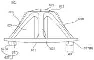
参照图2至图4,每个升降器61a、61b、62a、62b、63a以及63b包括固定到滚筒51的升降器框架620和被构造为覆盖升降器框架620的框架盖640。框架盖640从滚筒51的内周面径向向内(朝向滚筒51的内部)突出,并且与衣物接触。框架盖640借助于升降器框架620固定到滚筒51,而不是直接固定到滚筒51。2 to 4 , each
升降器框架620可以由合成树脂制成。升降器框架620优选地通过注塑成型形成,但本公开不限于此。The
由金属制成的升降器不仅强度优异,而且豪华卫生。为了将升降器直接联接到由金属制成的滚筒,必须将升降器焊接到以展开的滚筒形状切出的原料,将原料卷成圆柱形,然后在原料的两端彼此相遇的位置将其焊接在一起。然而,扁平的原料在卷起原料的过程期间变弯曲,因此,担心应力可能施加于升降器与滚筒之间的焊接部分并使焊接部分分离。Lifters made of metal are not only strong but also luxurious and hygienic. In order to couple the lifter directly to the drum made of metal, the lifter must be welded to the stock cut out in the shape of the unrolled drum, rolled into a cylindrical shape, and then welded where the ends of the stock meet each other together. However, the flat stock material becomes bent during the process of rolling up the stock material, and therefore, there is a concern that stress may be applied to the welded portion between the lifter and the drum and separate the welded portion.
为了解决这种担心,本公开提出一种构造,在该构造中,由金属制成的框架盖640借助于由合成树脂制成的升降器框架620固定到滚筒51。In order to address this concern, the present disclosure proposes a configuration in which the
同时,参照图3和图8至图12,升降器框架620的整个外表面620a(参见图8)具有凸形,并且升降器框架620的内表面620b(参见图9)具有凹形。具体地,升降器框架620可以包括框架基座621、框架上板623以及框架侧壁622。Meanwhile, referring to FIGS. 3 and 8 to 12 , the entire
框架基座621固定到滚筒51的内周面。框架基座621可以具有在其中心部分处开口的环形状(或由单线形成的闭合形状)。The
框架上板623在朝向滚筒51的内部的方向上与框架基座621隔开,并且借助于框架侧壁622连接到框架基座621。框架侧壁622可以形成为管状(或圆柱)体的形式,使得框架侧壁622的下端连接到框架基座621,并且框架侧壁622的上端连接到框架上板623。The frame
框架侧壁622被成形为使得其横截面的轮廓从连接到框架基座621的下端向上(或者沿滚筒51的径向)逐渐减小(或者沿远离滚筒51的内周面的方向逐渐减小),并且横截面的轮廓在与框架上板623相遇的部分处最小。The
可以在滚筒51中形成一个或多个水流入口孔,以便允许存储在储水桶31中的洗涤水引入到框架盖640的内部。在由框架盖640覆盖的区域中形成的任意开口部可以是水流入口孔。例如,被定位在框架盖640内部的一些通孔51h可以是水流入口孔。此外,下面将描述的安装槽缝511a和511b、紧固孔513a和513b以及开口部512a和512b可以是水流入口孔。One or more water inflow inlet holes may be formed in the
可以在升降器框架620中形成一个或多个水流通孔624和624a。任意开口都可以是水流通孔624,只要该开口形成在升降器框架620中并且允许升降器框架620的内部和外部彼此连通即可。One or more water flow holes 624 and 624a may be formed in the
水流通孔624可以形成在框架侧壁622和/或框架上板623中。存储在升降器框架620的凹空间中的洗涤水可以借助水流通孔624排出。The water flow holes 624 may be formed in the
可以在框架盖640中形成一个或多个水流排出孔646h,以将升降器61a、61b、62a、62b、63a以及63b中的洗涤水排出到滚筒51中。在升降器框架620内部的凹空间中的洗涤水可以穿过水流通孔624,然后可以借助水流排出孔646h排出到滚筒51中。One or more water
框架盖640的暴露于滚筒51的内部并与衣物接触的外表面640a具有凸形,并且框架盖640的内表面具有凹形,该凹形对应于升降器框架620的凸外表面620a。框架盖640可以由金属制成,优选地由不锈钢制成,但本公开不限于此。框架盖640可以通过对具有预定厚度的金属板进行塑性加工(例如压制)来形成。The
框架盖640可以包括:盖侧壁645,该盖侧壁从与框架基座621邻接的下端向上延伸;和盖上板646,该盖上板被构造为覆盖盖侧壁645的上侧。盖上板646近似平行于框架上板623。多个水流排出孔646h可以形成在盖上板646中。The
盖侧壁645被成形为使得其横截面的轮廓从下端向上(或者沿滚筒51的径向)逐渐减小(或者沿远离滚筒51的内周面的方向逐渐减小),并且横截面的轮廓在与盖上板646相遇的部分处最小。The
升降器框架620包括间隔件625,这些间隔件从框架上板623突出,以便允许框架盖640与框架上板623隔开。间隔件625从框架上板623突出到框架盖640的内表面。The
框架盖640的内表面可以与框架上板623隔开一定程度,该程度等于或大于从框架上板623突出的间隔件625的长度(或高度)。间隔件625可以与框架盖640的内表面隔开预定距离。在这种情况下,框架盖640的内表面与框架上板623隔开的距离等于间隔件625的高度和间隔件625与框架盖640的内表面之间的间隔之和。当框架盖640受到外力挤压时,框架盖640与框架上板623接触,使得防止框架盖640产生进一步任何变形。The inner surface of the
另选地,根据实施方式,间隔件625可以被构造为与框架盖640接触。在这种情况下,间隔件625从升降器框架620的外表面620a突出并且邻接框架盖640的内表面。因为间隔件625在框架上板623与框架盖640隔开的状态下支撑框架盖640的内表面,所以即使框架盖640被外力压向升降器框架620,也可以维持框架盖640与框架上板623隔开的状态。Alternatively, according to an embodiment, the
间隔件625可以具有十字形的肋结构。具体地,间隔件625可以包括:垂直肋625a,该垂直肋在升降器框架620的纵向(或前后方向)上在框架上板623上延伸;和水平肋625b,该水平肋在与垂直肋625a交叉的同时延伸。垂直肋625a和水平肋625b可以彼此正交。The
参照图10,盖上板646的内表面可以与框架上板623的外表面隔开。即,可以在盖上板646的内表面与框架上板623的外表面之间形成预定的分离空间(或间隙g1),并且分离空间g1可以充当将洗涤水引导至水流排出孔646h的流路。Referring to FIG. 10 , the inner surface of the cover
还可以在框架侧壁622与盖侧壁645之间形成分离空间g2。下面要描述的安置槽621r(参见图8和图9)形成在框架基座621中,并且布置在朝向框架基座621的外部与框架侧壁622隔开预定距离的位置处。因此,盖侧壁645的被定位在安置槽621r中的下端与框架侧壁622隔开。因为框架盖640的下端通过安置槽621r与框架侧壁622隔开,并且盖上板646通过间隔件625与框架上板623隔开,所以框架盖640的下端和框架盖640的由间隔件625支撑的部分的框架盖640这两个点与升降器框架620强制隔开,因此,维持被定位在这两点之间的盖侧壁645与升降器框架620隔开的状态。A separation space g2 may also be formed between the
被引入到每个升降器61a、61b、62a、62b、63a以及63b中的洗涤水被引入到分离空间g1和g2中,并且在洗涤桶50旋转期间在分离空间g1和g2中形成的水流清洁升降器框架620的外表面和框架盖640的内表面。在清洁过程期间产生的异物可以借助形成在框架盖640中的水流排出孔646h或借助形成在滚筒51中的水流入口孔排出。通过分离空间g1和g2在升降器框架620与框架盖640之间形成流路,因此,该构造在将升降器61a、62a、63a、61b、62b以及63b维持在清洁状态方面可以是有利的。The wash water introduced into each
框架盖640可以具有形成在与间隔件625对应的位置处的拱顶641、642、643以及644。即,间隔件625可以布置在拱顶641、642、643以及644下方。在示例性实施方式中形成有多个间隔件625的情况下,可以在与多个间隔件625对应的位置处分别形成多个拱顶641、642、643以及644。The
拱顶641、642、643以及644可以形成在盖上板646上。每个拱顶641、642、643以及644的面向间隔件625的内表面可以凹陷地形成,并且每个拱顶641、642、643以及644的外表面可以凸出地形成。每个拱顶641、642、643以及644的凹陷内表面可以接触间隔件625。
拱顶641、642、643以及644通过挤压由金属制成的盖上板646来凸出地形成。多个拱顶641、642、643以及644可以沿盖上板646的纵向(或升降器61a、61b、62a、62b、63a以及63b的纵向)布置。一个或多个水流排出孔646h可以形成在相邻的拱顶641、642、643以及644之间。The
拱顶641、642、643以及644可以包括两个或更多个拱顶,这些拱顶的内表面的凹部的深度彼此不同。更详细地,拱顶641、642、643以及644可以包括:大拱顶641和644,每个大拱顶均具有第一深度的凹部;和小拱顶642和643,每个小拱顶均具有第二深度的凹部,第二深度小于第一深度。对应于大拱顶641和644的间隔件625a和625d的高度可以大于对应于小拱顶642和643的间隔件625b和625c的高度。The
拱顶641、642、643以及644可以包括具有不同尺寸的两个或更多个拱顶。每个拱顶641、642、643以及644均可以具有圆形形状,但本公开不必限于此。这里,可以基于当从上方观察每个拱顶641、642、643以及644的内表面的凹部时的形状来确定“尺寸”,例如,“尺寸”可以被定义为凹部的直径。然而,由于每个拱顶641、642、643以及644的内径与外径之间的差仅是由于材料的厚度所致,因此尺寸可以基于每个拱顶641、642、643以及644的外径来定义。
间隔件625的尺寸也可以根据每个拱顶641、642、643以及644的尺寸变化。即,在如图13例示存在大拱顶641和644以及小拱顶642和643的情况下,对应于大拱顶641和644的间隔件625可以大于对应于小拱顶642和643的间隔件625。The dimensions of the
两个小拱顶643和644可以定位在一对大拱顶641与642之间,并且水流排出孔646h可以形成在拱顶641、642、643以及644之间。多个水流排出孔646h可以沿与升降器61a、61b、62a、62b、63a以及63b交叉的方向(或与每个升降器61a、61b、62a、62b、63a以及63b的长度正交的方向)设置。Two
在储水桶31中存储的水借助开口部引入到升降器61a、61b、62a、62b、63a以及63b中。升降器框架620是具有一个或多个水流通孔624的结构,并且引入到升降器61a、61b、62a、62b、63a以及63b中的水可以借助水流通孔624到达水流排出孔646h。The water stored in the
在洗涤水处于升降器61a、61b、62a、62b、63a以及63b中的状态下,被引入到升降器61a、61b、62a、62b、63a以及63b中的洗涤水通过洗涤桶50的旋转而升高,并且在该过程中,借助水流排出孔646h排出(或喷射)洗涤水。The wash water introduced into the
参照图2、图3、图10以及图13至图15,框架盖640可以包括具有环形的一个或多个洗涤突起603和604、或从盖侧壁645的外表面突出的一个或多个洗涤环。多个洗涤突起603和604可以彼此平行地布置。在示例性实施方式中,设置了两个洗涤突起603和604,但本公开不必限于此。在框架盖640由金属制成的情况下,洗涤突起603和604可以通过挤压形成。2, 3, 10, and 13-15, the
每个洗涤突起603和604均具有与盖侧壁645的轮廓对应(或类似)的形状,并且优选地,洗涤突起可以从盖侧壁645突出到预定高度。由于盖侧壁645的轮廓在洗涤突起603和604之间向上减小,因此被定位在上侧的洗涤突起小于另一个洗涤突起。Each of the
施加在衣物与洗涤突起603和604之间的摩擦力生成摩擦衣物的效果,从而提高洗涤能力。另外,因为洗涤突起603和604有助于提起衣物的操作,所以即使在每个升降器61a、61b、62a、62b、63a以及63b的高度被减小至小于相关技术中的高度时,也可以向衣物施加与相关技术水平相同的物理力(例如用于提起或撞击衣物的力)。The frictional force applied between the laundry and the
框架盖640可以联接到升降器框架620。参照图2和图3,可以在框架盖640的下端处形成一个或多个联接突片648。如图14例示,当从前侧观察框架盖640时,联接突片648可以形成在下端的左侧645L或右侧645R。左侧645L和右侧645R可以是在前后方向上延伸的笔直段。The
参照图8和图9,可以在升降器框架620中形成供联接突片648从上方穿过的突片结合端口621h。突片结合端口621h可以分别形成在与联接突片648对应的位置处。联接突片648穿过突片结合端口621h,并且联接突片648的穿过部分弯曲并被突片结合端口621h的边缘(或框架基座621的底表面)捕获,使得升降器框架620和框架盖640可以联接到彼此。8 and 9 , a
同时,对应于框架盖640的下端的安置槽621r可以形成在升降器框架620的框架基座621中。框架盖640的下端可以插入并安置在安置槽621r中。在这种情况下,突片结合端口621h可以形成在安置槽621r中。Meanwhile, a
在下文中,将描述升降器框架620和滚筒51联接到彼此的结构。Hereinafter, a structure in which the
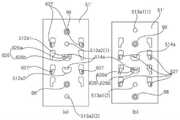
参照图8、图9、图11以及图12,一个或多个插入突起627可以形成在前升降器61a、62a以及63a和/或后升降器61b、62b以及63b中的每一个上。进一步地,参照图5至图7,滚筒51可以具有第一组G1中的安装槽缝511a1和第二组G2中的安装槽缝511a2。组G1和G2中的每一个均可以包括一个或多个安装槽缝511a1(1)至511a1(4)。在此,“组”是一组安装槽缝,并且可以包括一个或多个安装槽缝。8, 9, 11 and 12, one or
第一组G1中的安装槽缝511a1和第二组G2中的安装槽缝511a2可以包括与一个或多个插入突起627的数量对应的若干安装槽缝511a1(1)至511a1(4)以及511a2(1)至511a2(4)。即,在第一组G1和第二组G2中的安装槽缝用于安装前升降器61a、62a以及63a的情况下,第一组G1中的安装槽缝511a1的数量和第二组G2中的安装槽缝511a2的数量可以对应于设置在每个前升降器61a、62a以及63a上的插入突起627的数量。The mounting slots 511a1 in the first group G1 and the mounting slots 511a2 in the second group G2 may include several mounting slots 511a1(1) to 511a1(4) and 511a2 corresponding to the number of the one or more insertion protrusions 627 (1) to 511a2(4). That is, in the case where the mounting slots in the first group G1 and the second group G2 are used for mounting the
同样,根据实施方式,在第一组G1和第二组G2中的安装槽缝用于安装后升降器61b、62b以及63b的情况下,第一组G1中的安装槽缝511a1的数量和第二组G2中的安装槽缝511a2的数量可以对应于设置在每个后升降器61b、62b以及63b上的插入突起627的数量。Also, according to the embodiment, in the case where the mounting slots in the first group G1 and the second group G2 are used for mounting the
形成在前升降器61a、62a以及63a或后升降器61b、62b以及63b中的每一个上的一个或多个插入突起627可以选择性地紧固到第一组G1或第二组G2中的安装槽缝511a2。升降器的安装位置可以根据是否将形成在每个升降器61a、62a、63a、61b、62b以及63b上的一个或多个插入突起627插入到构成第一组G1或第二组G2中的任意一个的安装槽缝中来确定。One or
在下文中,将描述使用构成第一组G1和第二组G2的安装槽缝511a来安装前升降器61a、62a以及63a的示例,但安装槽缝可以为了安装后升降器61b、62b以及63b而以相同的方式来形成。Hereinafter, an example in which the
在第二组G2中的安装槽缝511a2与第一组G1中的安装槽缝511a1重叠的范围内,第二组G2中的安装槽缝511a2形成在向后移位的区域中。作为参考,在图6中,第一区域M1指示形成第一组G1中的安装槽缝511a1的区域,并且第二区域M2指示形成第二组G2中的安装槽缝511a2的区域。在下文中,如图6例示,第二组G2中的安装槽缝511a2从第一组G1中的安装槽缝511a1向后布置。The mounting slits 511a2 in the second group G2 are formed in a rearwardly displaced region within a range where the mounting slits 511a2 in the second group G2 overlap with the mounting slits 511a1 in the first group G1. For reference, in FIG. 6 , the first region M1 indicates a region where the mounting slots 511a1 in the first group G1 are formed, and the second region M2 indicates a region where the mounting slots 511a2 in the second group G2 are formed. Hereinafter, as illustrated in FIG. 6, the mounting slots 511a2 in the second group G2 are arranged rearward from the mounting slots 511a1 in the first group G1.
参照图5至图7,第二组G2中的安装槽缝511a2与第一组G1中的安装槽缝511a1在向后方向上以预定距离D隔开。因此,当将插入突起627安装在第一组G1中的安装槽缝511a1中时,与将插入突起627安装在第二组G2中的安装槽缝511a2中的情况相比,每个前升降器61a、62a以及63a均进一步向前定位距离D。如图5例示,与滚筒是小容量滚筒的情况相比,大容量滚筒51的金属板进一步向前延伸距离E。在大容量滚筒的情况下(图5的(a)),前升降器61a、62a以及63a通过使用第一组G1中的安装槽缝511a1来安装,使得与滚筒是小容量滚筒的情况(图5的(b))相比,前升降器61a、62a以及63a可以相对进一步向前地安装。因此,在滚筒51旋转的同时,定位在与距离E对应的区域中的衣物可以容易地与前升降器61a、62a以及63a接触。5 to 7 , the mounting slots 511a2 in the second group G2 are spaced apart from the mounting slots 511a1 in the first group G1 by a predetermined distance D in the rearward direction. Therefore, when the
各个组G1和G2中的安装槽缝511a可以在前后方向上成排布置。特别地,每个组G1和G2中的安装槽缝511a布置成两排。进一步地,当在不区分组的情况下观察整体构造时,安装槽缝511a可以沿着在前后方向上延伸的公共基准线设置。优选地,在本实施方式中,安装槽缝布置在彼此平行的两条直线上。The mounting
更详细地,第一组G1中的安装槽缝511a1可以包括两个或更多个第一安装槽缝511a1(1)和511a1(2),它们以第一间隔T设置成沿前后方向延伸的第一排P1。此外,第一组G1中的安装槽缝511a1还可以包括两个或更多个第一安装槽缝511a1(3)和511a1(4),它们以第一间隔T设置成与第一排P1平行的第二排P2。In more detail, the mounting slots 511a1 in the first group G1 may include two or more first mounting slots 511a1(1) and 511a1(2) arranged at a first interval T to extend in the front-rear direction First row P1. In addition, the mounting slots 511a1 in the first group G1 may also include two or more first mounting slots 511a1(3) and 511a1(4) arranged at a first interval T parallel to the first row P1 The second row of P2.
第二组G2中的安装槽缝511a2可以包括两个或更多个第二安装槽缝511a2(1)和511a2(2),它们在从第一组G1中的安装槽缝511a1向后移位第二间隔D的位置处设置成第一排P1,第二间隔D小于第一间隔T。The mounting slots 511a2 in the second group G2 may include two or more second mounting slots 511a2(1) and 511a2(2) that are displaced rearwardly from the mounting slots 511a1 in the first group G1 The positions of the second interval D are arranged in the first row P1, and the second interval D is smaller than the first interval T. As shown in FIG.
此外,第二组G2中的安装槽缝511a2还可以包括两个或更多个第二安装槽缝511a2(3)和511a2(4),它们在从第一组G1中的安装槽缝511a1向后移位第一间隔T的位置处设置成第二排P2。In addition, the mounting slots 511a2 in the second group G2 may further include two or more second mounting slots 511a2(3) and 511a2(4), which are located in the direction from the mounting slots 511a1 in the first group G1 to the The position displaced by the first interval T afterward is set as the second row P2.
在下文中,可以用于安装前升降器61a、62a以及63a的安装槽缝511a1和511a2被定义为在前升降器安装组中,并且可以用于安装后升降器61b、62b以及63b的安装槽缝511b(参见图6的(a))被定义为在后升降器安装组中。Hereinafter, the mounting slots 511a1 and 511a2 that can be used to mount the
多个前升降器或后升降器61a、62a、63a、61b、62b以及63b可沿滚筒51的周向布置,使得多个前升降器安装组可以沿周向布置,并且同样地,多个后升降器安装组也可以沿周向布置。A plurality of front or
在下文中,属于前升降器安装组的安装槽缝被称为前安装槽缝511a,并且属于后升降器安装组的安装槽缝被称为后安装槽缝511b。Hereinafter, a mounting slot belonging to the front lifter mounting group is referred to as a
参照图8至图12,插入突起627可以从框架基座621突出。插入突起627可以包括从框架基座621的底表面向下突出的竖直部627a(参见图11)以及从竖直部627a沿水平方向弯曲的捕获部627b。当从上方观察时,捕获部627b可以朝向环形框架基座621的内部突出。Referring to FIGS. 8 to 12 , the
如图11例示,当从前侧观察升降器框架620时,插入突起627可以分别形成在框架基座621的左侧和右侧。两个或更多个插入突起627可以沿着框架基座621的一侧(或在前后方向上)形成。As illustrated in FIG. 11 , when the
具体地,形成在框架基座621的左侧的插入突起627(L)可以包括向右弯曲的捕获部627b。相反,形成在框架基座621的右侧的插入突起627(R)可以包括向左弯曲的捕获部627b。Specifically, the insertion protrusion 627(L) formed on the left side of the
参照图6,每个安装槽缝511a和511b均可以被成形为在滚筒51的近似前后方向上具有长度L1。每个安装槽缝511a和511b均可以包括:插入段S1,该插入段具有预定宽度W1;和结合段S2,该结合段从插入段S1向后或向前延伸,并且宽度小于插入段S1(W2<W1)。在示例性实施方式中,结合段S2从插入段S1的后端向后延伸,但本公开不必限于此。相反,结合段S2可以从插入段S1的前端向前延伸。Referring to FIG. 6 , each of the mounting
此外,如下面要描述的图20例示,在示例性实施方式中,前安装槽缝511a的结合段S2可以从插入段S1的前端向前延伸,并且后安装槽缝511b的结合段S2可以从插入段S1的后端向后延伸。Furthermore, as illustrated in FIG. 20 to be described below, in an exemplary embodiment, the coupling section S2 of the
同时,参照图5至图7,当将升降器框架620安装在滚筒51中时,升降器框架620的插入突起627穿过插入段S1,并且升降器框架620被向后推动,使得竖直部627a沿着结合段S2向前移动,由此,捕获部627b被定位在结合段S2的下方。在这种情况下,由于框架基座621的底表面与滚筒51的内周面紧密接触,并且捕获部627b的宽度W3(参见图11)大于结合段S2的宽度W2,因此捕获部627b不能从下侧向上侧穿过结合段S2。Meanwhile, referring to FIGS. 5 to 7 , when the
参照图8至图11,框架侧壁622可以包括下端连接到框架基座621的左侧621a的侧壁左部622L和下端连接到框架基座621的右侧621b的侧壁右部622R。侧壁左部622L或侧壁右部622R中的至少一个可以相对于框架基座621限定锐角。特别地,侧壁左部622L或侧壁右部622R中的至少一个在从前侧观察时可以彼此对称。8 to 11 , the
当从上方竖直向下观看升降器框架620时,框架侧壁622可以具有形成在与插入突起627对应的位置处的横向通孔624a。横向通孔624a可以形成在侧壁左部622L或侧壁右部622R中的至少一个中。When the
升降器框架620可以通过注塑成型形成。在这种情况下,模具可以包括形成升降器框架620的上表面的上模具和形成升降器框架620的下表面的下模具。The
插入突起627的上表面可以由上模具形成。由于插入突起627被定位在框架侧壁622的下侧,因此限定插入突起627的上表面的上模具的一部分在打开模具的过程中可以穿过的开口部需要形成在沿上模具在框架侧壁622上开口的方向(或从框架基座621竖直向上的方向)与插入突起627重叠的区域中,使得在打开模具的过程中,形成插入突起627的上表面(特别是捕获部627b的上表面)的上模具的模具部可以向上移动(或使得上模具可以无底切地退出),并且横向通孔624a是开口部。作为参考,图11中的PL指示由上模具和下模具形成的分型线。The upper surface of the
在这种情况下,因为横向通孔624a是在使用模具的模制过程期间弹出一部分模具所需的构造,所以横向通孔624a可以被称为“模具弹出端口”。In this case, the lateral through-
如图8例示,当从上方竖直向下观察升降器框架620时(在下文中,被称为“升降器框架的平面图”),插入突起627的捕获部627b被定位在横向通孔624a中(或与横向通孔624a重叠)。特别地,整个捕获部627b被定位在横向通孔624a中。进一步地,在升降器框架的平面图中,除了连接到竖直部627a的部分627a以外,捕获部627b的外周与横向通孔624a的边缘隔开。8 , when the
另外,安置槽621r可以沿着框架基座621的圆周以闭合曲线的形式延伸,并且插入突起627的捕获部627b的水平投影平面可以定位在安置槽621r的闭合曲线中。即,插入突起627的捕获部627b可以布置在被安置槽621r包围的内部中。In addition, the
因此,框架基座621的具有由安置槽621r形成的闭合曲线的部分的负载可以在某种程度上减小,从而防止该部分在结构上变弱。Therefore, the load of the portion of the
进一步地,如图11例示,框架侧壁622的下端连接到框架基座621的部分可以具有比其他部分相对更高的刚度。由此,就结构刚度而言,插入突起627的竖直部627a和框架侧壁622的下端在纵向上彼此对应的构造可以是有利的。Further, as illustrated in FIG. 11 , the part where the lower end of the
参照图9和图10,捕获突起626可以形成在前升降器61a、62a以及63a或后升降器61b、62b以及63b中的至少一个上。捕获突起626可以从升降器框架620的凹陷内表面620b向下突出。9 and 10 , a capturing
参照图6,可以在滚筒51中形成插入有捕获突起626的开口部512a和512b。用于安装前升降器61a、62a以及63a的一对开口部512a1和512a2可以在前后方向上彼此隔开间隔D。Referring to FIG. 6 , opening
根据插入突起627是插入到第一组G1中的安装槽缝511a1还是第二组G2中的安装槽缝511a2中,来将捕获突起626选择性地插入到一对开口部512a1和512a2中的任意一个中。The
各与捕获突起626的下端接触(或被捕获突起626的下端捕获)的捕获突片514a和514b可以形成在开口部512a和512b的边缘上。捕获突片514a和514b可以与开口部512a和512b中的捕获突起626的侧表面接触,从而限制捕获突起626的横向移动。Capturing
同时,可以基于安装槽缝511a和511b相对于结合段S2的插入段S1的相对位置来确定捕获突片514a和514b的位置。即,如图6例示,当结合段S2被定位在插入段S1的后面时,捕获突片514a和514b被定位在捕获突起626的前侧的第一凹部626a中。捕获突片514a和514b可以从开口部512的前端向后延伸,以在捕获突起626将要向前移动(即,插入突起627将要从结合段S2向插入段S1移动)时限制捕获突起626的移动。Meanwhile, the positions of the
相反,与如图20例示的安装槽缝511a一样,当结合段S2定位在插入段S1的前面时,捕获突片514a和514b被定位在捕获突起626的后侧的第二凹部626b中。捕获突片514a和514b可以从开口部512的后端向前延伸,以在捕获突起626将要向后移动(即,插入突起627将要从结合段S2向插入段S1移动)时限制捕获突起626的移动。In contrast, like the mounting
捕获突片514a和514b可以基于连接到开口部512a和512b的边缘的部分以相对于滚筒51的外部的预定角度弯曲。The capturing
即使在捕获突起626的下端未插入到开口部512a和512b中的状态下,捕获突起626的侧表面也可以与捕获突片514a和514b接触。当升降器框架620将要移动(即,将要沿与安装升降器框架620的方向相反的方向移动)使得竖直部627a从结合段S2移动到插入段S1时,移动随着捕获突片514a和514b与捕获突起626的下端干扰而受到限制。Even in a state where the lower ends of the capturing
参照图9,在捕获突起626的下端处,第一凹部626a可以形成在面向捕获突片514a和514b的那一侧处。在升降器框架620已经完全安装的状态下,捕获突片514a和514b可以定位在第一凹部626a中。9, at the lower end of the capturing
在捕获突起626的下端处,第二凹部626b可以进一步形成在与第一凹部626a相对的那一侧处。当在升降器框架620的前侧和后侧被改变的状态下安装升降器框架620时,捕获突片514a和514b可以定位在第二凹部626b中。At the lower end of the capturing
参照图9,紧固凸台628可以形成在前升降器61a、62a以及63a或后升降器61b、62b以及63b中的至少一个上。紧固凸台628可以从升降器框架620的内表面620b向下突出。紧固凸台628可以从框架上板623延伸。两个或更多个紧固凸台628可以被设置为沿前后方向彼此隔开。9, a
参照图5和图6,紧固孔513a和513b可以形成在滚筒51中。紧固孔513a和513b可以包括:第一紧固孔513a1,该第一紧固孔513a1形成在当升降器框架620的插入突起627安装在第一组G1中的安装槽缝511a1中时与紧固凸台528对应的位置处;和第一紧固孔513a2,该第一紧固孔513a2形成在当升降器框架620的插入突起627安装在第二组G2中的安装槽缝511a2中时与紧固凸台528对应的位置处。一对第一紧固孔513a1(1)和513a1(2)被设置为对应于一对紧固凸台528,并且可以设置包括一对第二紧固孔513a2(1)和513a2(2)的第二紧固孔513a2。Referring to FIGS. 5 and 6 , fastening holes 513 a and 513 b may be formed in the
参照图7,紧固凸台628可以基于插入突起627是插入第一组G1中的安装槽缝511a1还是第二组G2中的安装槽缝511a2中借助于预定的紧固构件(在下文中,为了示例性目的,为螺钉98)选择性地紧固到第一紧固孔513a1或第二紧固孔513a2。Referring to FIG. 7 , the
在将插入突起627插入到安装槽缝511a中并且临时组装升降器框架620的状态下,螺钉98从滚筒51的外部穿过紧固孔513a,然后被紧固到紧固凸台628,使得升降器框架620可以被完全安装。In a state where the
同时,如上所述,如图7的(a)或(b)例示,升降器框架620的安装位置可以根据插入突起627是插入到安装槽缝511a1还是安装槽缝511a2中而变化。在任意情况下,在升降器完全安装的状态下,安装槽缝511a1和511a2、开口部512a1和512a2以及紧固孔513a1和513a2被框架盖640遮盖。即,安装槽缝511a1和511a2、开口部512a1和512a2以及紧固孔513a1和513a2被定位在框架盖640的内部,由此不暴露于滚筒51的内部。Meanwhile, as described above, as illustrated in (a) or (b) of FIG. 7 , the installation position of the
换句话说,在设置在每个升降器61a、62a、63a、61b、62b以及63b上的至少一个插入突起627被紧固到第一组G1和第二组G2中的安装槽缝511a当中的任意一组(例如G1)的安装槽缝(例如511a1)的状态下,另一组(例如G2)中的安装槽缝(例如511a2)可以被升降器隐藏在滚筒51内。In other words, at least one
更详细地,在设置在每个前升降器61a、62a以及63a上的至少一个插入突起627被插入到第一组G1和第二组G2当中的任意一组(例如G1)中的安装槽缝中的状态下,每个前升降器61a、62a以及63a的前端可以从属于第一组G1和第二组G2的安装槽缝511a1(1)至511a1(4)和511a2(1)至511a2(4)向前定位。In more detail, at least one
另外,每个前升降器61a、62a以及63a的后端可以从属于第一组G1和第二组G2的任意安装槽缝511a1(1)至511a1(4)和511a2(1)至511a2(4)向后定位。In addition, the rear end of each of the
由于用于安装前升降器61a、62a以及63a的所有安装槽缝511a1(1)至511a1(4)以及511a2(1)至511a2(4)被定位在前升降器61a、62a以及63a的前端与后端之间,安装槽缝可以通过被前升降器61a、62a以及63a覆盖来隐藏。Since all the mounting slots 511a1(1) to 511a1(4) and 511a2(1) to 511a2(4) for mounting the
衣物处理设备的制造商有时生产具有不同容量的滚筒的各种类型的产品。在这种情况下,基于预定的标准,切出具有安装槽缝511a和511b、开口部512a和512b、紧固孔513a和513b等的金属板,卷起这样切出的原料51'或51”(参见图5),并且将原料的端部接合在一起,以便制造滚筒51。在这种情况下,基于滚筒的标准将金属板切割至预定的长度。为了制造具有不同长度的两个滚筒,需要根据滚筒的长度来不同地调节前升降器61a、62a以及63a与后升降器61b、62b以及63b之间的间隔。Manufacturers of laundry treatment equipment sometimes produce various types of products with drums of different capacities. In this case, based on a predetermined standard, a metal plate having mounting
例如,如图5例示,在滚筒51'的长度较长时的前升降器61a、62a以及63a与后升降器61b、62b以及63b之间的间隔(参见图5的(a))需要大于在滚筒51”的长度较短时的前升降器61a、62a以及63a与后升降器61b、62b以及63b之间的间隔(参见图5的(b)),使得即使在大容量滚筒51的情况下,衣物也可以通过前后升降器61b、62b以及63b均匀地提起。For example, as illustrated in FIG. 5 , the interval between the
因此,在滚筒51中还形成额外安装槽缝511a,以便在改变滚筒的长度时调节前升降器61a、62a以及63a或后升降器61b、62b以及63b中的至少一个在前后方向上的安装位置。Therefore, an
在本示例性实施方式中,额外安装槽缝511a被设置为调节前升降器51a、52a以及53a的安装位置,但本公开不必限于此。根据示例性实施方式,额外安装槽缝511b可以被设置为调节后升降器61b、62b以及63b的安装位置。In the present exemplary embodiment, the
额外安装槽缝511a可以形成在升降器框架620中,使得额外安装槽缝511a在数量上对应于插入有插入突起627的安装槽缝511a(下文中,称为“安装槽缝”),并且额外安装槽缝511a可以形成在沿向前或向后方向与各安装槽缝隔开预定距离D的点处。通过将插入突起627与安装槽缝(例如511a1)分离,然后将插入突起627插入额外安装槽缝(例如511a2)中,可以将升降器框架620的安装位置改变距离D。The
同时,在示例性实施方式中,额外开口部512a被设置为调节前升降器51a、52a以及53a的安装位置,但本公开不必限于此。根据实施方式,额外开口部512b也可以被设置为调节后升降器61b、62b以及63b的安装位置。Meanwhile, in the exemplary embodiment, the additional opening portion 512a is provided to adjust the installation positions of the
同时,在示例性实施方式中,额外紧固孔513a被设置为调节前升降器51a、52a以及53a的安装位置,但本公开不限于此。根据实施方式,额外紧固孔513b也可以被设置为调节后升降器61b、62b以及63b的安装位置。Meanwhile, in the exemplary embodiment, the
图20例示了本公开的另一个示例性实施方式。为了借助于前安装槽缝511a安装升降器框架620,需要在将插入突起627插入到插入段S1中之后向前推动升降器框架620。为了借助于后安装槽缝511b安装升降器框架620,需要在将插入突起627插入到插入段S1中之后向后推动升降器框架620。FIG. 20 illustrates another exemplary embodiment of the present disclosure. In order to install the
相反,为了将升降器框架620与滚筒51分离,向前或向后推动升降器框架620,以使插入突起627的捕获部627b从结合段S2移动并使捕获部627b与插入段S1对齐,并且提起升降器框架620,使得捕获部627b穿过插入段S1,并且升降器框架620可以与滚筒51分离。Conversely, in order to separate the
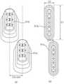
图16是例示了图1所例示的一对前后升降器的视图。图17是例示了从前侧观察时的图16所例示的升降器的视图。图18是例示了图1所例示的滚筒展开的状态的视图(a)和布置有根据本公开的另一个示例性实施方式的升降器的滚筒的展开图(b)。图19是例示了根据滚筒的旋转角度由后升降器引起的第一织物的高度变化的视图(a)和例示了由与后升降器一起构成一组的前升降器引起的第二织物的高度变化的视图(b)。在下文中,将参照图16至图19进行描述。FIG. 16 is a view illustrating a pair of front and rear lifters illustrated in FIG. 1 . FIG. 17 is a view illustrating the lifter illustrated in FIG. 16 when viewed from the front side. 18 is a view (a) illustrating a state where the drum illustrated in FIG. 1 is unfolded and a development view (b) of the drum in which the lifter according to another exemplary embodiment of the present disclosure is arranged. 19 is a view (a) illustrating a height change of the first fabric caused by the rear lifter according to the rotation angle of the drum and illustrating the height of the second fabric caused by the front lifter constituting a group with the rear lifter Changed view (b). Hereinafter, description will be made with reference to FIGS. 16 to 19 .
每个前升降器61a、62a以及63a均布置在滚筒51的内周面上并且在前后方向上延伸。多个前升降器61a、62a以及63a基于旋转轴线O以相等角度布置。Each of the
后升降器61b、62b以及63b布置在滚筒51的内周面上,并且从前升降器61a、62a以及63a向后定位。像前升降器61a、62a以及63a一样,后升降器61b、62b以及63b基于旋转轴线O以相等的角度布置。The
后升降器61b、62b以及63b被布置为相对于旋转轴线O与前升降器61a、62a以及63a形成预定的相位角。这里,“相位角”通过将升降器61a、62a、63a、61b、62b以及63b到达圆周上的点的时间点定义为滚筒51的旋转角来形成。假设在示例性实施方式中滚筒51沿顺时针方向CW旋转,则后升降器61b、62b以及63b先于前升降器61a、62a以及63a对应于相位角Δθ的程度达到相同的高度。The
如图16和图17例示,假设每个升降器61a、62a、63a、61b、62b以及63b具有在前后方向上延伸的长度C1和在左右方向(或与纵向正交的方向)上定义的宽度C2,则对应于相位角的圆周距离(C3=Δθr,参见图19)大于0且等于或小于在每个前升降器61a、62a以及63a的周向上的宽度C2的两倍。16 and 17, it is assumed that each
参照图18,在滚筒51的内周面上的任意一对前/后升降器(例如61a和61b)与另一对前/后升降器(例如62a和62b)之间形成没有前升降器或后升降器的无升降器区域SE。无升降器区域SE可以从滚筒51的前端延伸到后端。Referring to FIG. 18 , between any pair of front/rear lifters (eg, 61 a and 61 b ) on the inner peripheral surface of the
具体地,无升降器区域SE从滚筒51的前端穿过相邻的两组升降器之间,并且延伸到滚筒51的后端。具体地,无升降器区域SE从滚筒51的前端笔直延伸到滚筒的后端,同时穿过多个前升降器61a、62a以及63a中的两个相邻的前升降器(例如61a和62a)之间和在各与两个相邻前升降器61a和62a中的每一个形成相位角Δθ的两个后升降器61b和62b之间。Specifically, the lifter-free area SE passes between the adjacent two sets of lifters from the front end of the
由于无升降器区域SE从滚筒51的前端笔直延伸到后端,因此衣物可以在无升降器区域SE中均匀地分配到滚筒51的前后区域。Since the lifter-free area SE extends straight from the front end to the rear end of the
通常,洗衣机在执行甩干过程之前检测滚筒51的偏心度,并且当检测到的偏心度在基准值内时,滚筒加速,使得滚筒51的旋转速度达到预定的甩干速度(或甩干RPM)。否则,执行织物分配,以改变织物在滚筒51中的位置。如果检测到的偏心度未达到基准值,则重复织物分配。当重复织物分配的次数达到预定次数时,确定织物分配失败,并且停止甩干。Generally, the washing machine detects the eccentricity of the
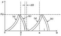
在根据本示例性实施方式的洗衣机中,被定位在滚筒51后侧的第一织物(即,将由后升降器61b、62b以及63b提起的织物)和被定位在滚筒51前侧的第二织物(即,将由前升降器提起的织物)以由前升降器61a、62a和63a以及后升降器61b、62b和63b形成的相位角Δθ的时间差(或相位差)流动,因此,可以更平滑地执行织物分配。In the washing machine according to the present exemplary embodiment, the first fabric positioned on the rear side of the drum 51 (ie, the fabrics to be lifted by the
更具体地,参照图19,当在后升降器61b、62b以及63b被定位在滚筒51的最低点(θ=0)的状态下使滚筒51沿顺时针方向CW旋转时,第一织物开始首先由后升降器61b、62b以及63b提起,然后在与相位角Δθ对应的时间过去之后,第二织物开始由前升降器61a、62a以及63a提起。More specifically, referring to FIG. 19, when the
假设织物滚动(θ<π/2)并且由升降器61a、62a、63a、61b、62b以及63b提起的织物落下的位置P为位置Pd,则由后升降器61b、62b以及63b提起的第一织物到达位置(或高度)Pd并首先落下,然后由前升降器61a、62a以及63a提起的第二织物到达位置Pd并落下。Assuming that the fabric rolls (θ<π/2) and the position P where the fabric lifted by the
第一织物和第二织物以时间差移动而不形成团,由此可以均匀地分配。因此,可以减少重复织物分配的次数,减少不能进入甩干阶段的情况,并且减少包括甩干时间的总洗涤时间。The first fabric and the second fabric move with a time difference without forming a clump, thereby allowing for even distribution. As a result, the number of repeated fabric dispenses can be reduced, the inability to enter the spin phase can be reduced, and the total wash time including spin time can be reduced.
另外,由于织物在织物滚动或翻滚时以相位差流动,因此由相对移动引起的织物之间的摩擦或碰撞更频繁地发生,使得可以通过洗涤操作更有效地去除污染物(即提高洗涤能力)。In addition, since the fabrics flow with a phase difference as the fabrics roll or tumble, friction or collision between the fabrics caused by relative movement occurs more frequently, allowing for more efficient removal of contaminants through the washing operation (ie, improved washing power) .
同时,图20是例示了布置升降器的修改示例的视图,其中,(a)例示了小容量的滚筒,并且(b)例示了大容量的滚筒。参照图20,一组前升降器61a、62a和63a以及后升降器61b、62b和63b可以在前后方向上布置成一排。即,构成一组的前升降器61a、62a和63a以及后升降器61b、62b和63b可以在同一条线上设置,而不在周向上彼此隔开。Meanwhile, FIG. 20 is a view illustrating a modified example of arranging the lifters, in which (a) a small-capacity drum is illustrated, and (b) a large-capacity drum is illustrated. 20, a set of
图21是例示了升降器的另一个示例性实施方式的视图。图21所例示的示例性实施方式提供了一种升降器64,该升降器包括在形状上与上述示例性实施方式略微不同但在详细构造上与上述示例性实施方式类似的升降器框架620'和框架盖640'。因此,与根据上述示例性实施方式的组成元件相同的组成元件将被分配有相同的附图标记,并且将省略其具体描述。FIG. 21 is a view illustrating another exemplary embodiment of the lifter. The exemplary embodiment illustrated in Figure 21 provides a
虽然已经关于本发明的实施方式说明了本发明,但应理解,本发明的各种修改对本领域技术人员而言在阅读说明书时将变得显而易见。因此,应理解,这里公开的本发明旨在覆盖落入所附权利要求范围内的这些修改。While the present invention has been described with respect to its embodiments, it is to be understood that various modifications of this invention will become apparent to those skilled in the art upon reading the specification. Therefore, it is to be understood that the invention disclosed herein is intended to cover such modifications as fall within the scope of the appended claims.
相关申请的交叉引用CROSS-REFERENCE TO RELATED APPLICATIONS
本申请要求韩国知识产权局中的、2019年2月1日提交的标题为“LAUNDRYTREATING APPARATUS”的韩国专利申请10-2019-0013925和2019年10月29日提交的标题为“LAUNDRY TREATING APPARATUS”的韩国专利申请10-2019-0135451的优先权权益,上述申请的整个公开内容通过引用并入本文。This application claims Korean Patent Application No. 10-2019-0013925, filed on Feb. 1, 2019, and entitled "LAUNDRYTREATING APPARATUS" in the Korean Intellectual Property Office, and filed on Oct. 29, 2019, entitled "LAUNDRY TREATING APPARATUS." The benefit of priority to Korean Patent Application No. 10-2019-0135451, the entire disclosure of which is incorporated herein by reference.
Claims (16)
Translated fromChineseApplications Claiming Priority (4)
| Application Number | Priority Date | Filing Date | Title |
|---|---|---|---|
| KR20190013925 | 2019-02-01 | ||
| KR10-2019-0013925 | 2019-02-01 | ||
| KR1020190135451AKR20200096089A (en) | 2019-02-01 | 2019-10-29 | Laundry treating apparatus |
| KR10-2019-0135451 | 2019-10-29 |
Publications (2)
| Publication Number | Publication Date |
|---|---|
| CN111519383A CN111519383A (en) | 2020-08-11 |
| CN111519383Btrue CN111519383B (en) | 2022-09-06 |
Family
ID=68916448
Family Applications (1)
| Application Number | Title | Priority Date | Filing Date |
|---|---|---|---|
| CN201911346077.3AExpired - Fee RelatedCN111519383B (en) | 2019-02-01 | 2019-12-24 | laundry treatment equipment |
Country Status (4)
| Country | Link |
|---|---|
| US (1) | US11408109B2 (en) |
| EP (1) | EP3690106B1 (en) |
| CN (1) | CN111519383B (en) |
| AU (1) | AU2020200662B2 (en) |
Citations (6)
| Publication number | Priority date | Publication date | Assignee | Title |
|---|---|---|---|---|
| FR2656344A1 (en)* | 1989-12-22 | 1991-06-28 | Bosch Siemens Hausgeraete | METHOD FOR MANUFACTURING PLASTIC COACHES FOR A DRUM WASHING MACHINE AND COACHES THUS MANUFACTURED. |
| CN1906349A (en)* | 2004-05-15 | 2007-01-31 | Lg电子株式会社 | Drum assembly for washing machine |
| EP2270272A1 (en)* | 2009-06-29 | 2011-01-05 | Electrolux Home Products Corporation N.V. | Washing machine |
| CN103031694A (en)* | 2011-09-29 | 2013-04-10 | 三星电子株式会社 | Washing machine |
| KR20140120549A (en)* | 2013-04-03 | 2014-10-14 | 엘지전자 주식회사 | A washing machine |
| CN106939490A (en)* | 2016-01-05 | 2017-07-11 | Lg电子株式会社 | Lifter for laundry treatment unit |
Family Cites Families (17)
| Publication number | Priority date | Publication date | Assignee | Title |
|---|---|---|---|---|
| DE2310435A1 (en)* | 1973-02-28 | 1974-12-12 | Bosch Siemens Hausgeraete | Laundry washer or dryer drum - has plastics driver ribs each with floor part and V-shaped rib part |
| DE3803195C2 (en)* | 1988-02-03 | 1994-08-18 | Bosch Siemens Hausgeraete | Driving scoop for a washing drum |
| JP3772821B2 (en) | 2001-10-23 | 2006-05-10 | エルジー電子株式会社 | Washing machine |
| KR100445654B1 (en) | 2002-01-09 | 2004-08-21 | 엘지전자 주식회사 | A lifter's installing structure of the drum type washer |
| DE10227957A1 (en) | 2002-06-22 | 2004-01-08 | Electrolux Home Products Corporation N.V. | Horizontal axis washing machine clothes drum has two part lifters axially separated at slightly different radial positions to increase tumbling effect |
| KR100493287B1 (en) | 2002-09-10 | 2005-06-02 | 엘지전자 주식회사 | lift in drum type washing machine |
| US7299665B2 (en)* | 2004-03-19 | 2007-11-27 | Lg Electronics Inc. | Lift for drum-type washing machine |
| KR20070119321A (en) | 2006-06-15 | 2007-12-20 | 엘지전자 주식회사 | Washing machine with drum lifter and drum forming method |
| KR100808204B1 (en) | 2007-04-10 | 2008-03-03 | 엘지전자 주식회사 | Drum Washing Machine |
| CN101668891A (en) | 2007-05-14 | 2010-03-10 | 大宇电子株式会社 | washing machine having filtering lifters |
| ATE549445T1 (en) | 2009-05-12 | 2012-03-15 | Electrolux Home Prod Corp | WASHING MACHINE |
| EP2385166A1 (en) | 2010-05-04 | 2011-11-09 | Electrolux Home Products Corporation N.V. | Washing machine |
| US9096965B2 (en) | 2010-08-09 | 2015-08-04 | Lg Electronics Inc. | Apparatus for treating laundry having a ring shaped circular guide |
| JP2012055349A (en) | 2010-09-06 | 2012-03-22 | Hitachi Appliances Inc | Drum type washing/drying machine |
| US9512551B2 (en) | 2011-10-24 | 2016-12-06 | Lg Electronics Inc. | Washing machine to produce three-dimensional motion |
| KR102053143B1 (en) | 2013-04-30 | 2019-12-06 | 엘지전자 주식회사 | A washing machine |
| KR102488373B1 (en) | 2015-09-04 | 2023-01-12 | 엘지전자 주식회사 | Laundry treating apparatus |
- 2019
- 2019-12-16EPEP19216473.9Apatent/EP3690106B1/enactiveActive
- 2019-12-24CNCN201911346077.3Apatent/CN111519383B/ennot_activeExpired - Fee Related
- 2020
- 2020-01-30AUAU2020200662Apatent/AU2020200662B2/enactiveActive
- 2020-01-31USUS16/778,264patent/US11408109B2/enactiveActive
Patent Citations (6)
| Publication number | Priority date | Publication date | Assignee | Title |
|---|---|---|---|---|
| FR2656344A1 (en)* | 1989-12-22 | 1991-06-28 | Bosch Siemens Hausgeraete | METHOD FOR MANUFACTURING PLASTIC COACHES FOR A DRUM WASHING MACHINE AND COACHES THUS MANUFACTURED. |
| CN1906349A (en)* | 2004-05-15 | 2007-01-31 | Lg电子株式会社 | Drum assembly for washing machine |
| EP2270272A1 (en)* | 2009-06-29 | 2011-01-05 | Electrolux Home Products Corporation N.V. | Washing machine |
| CN103031694A (en)* | 2011-09-29 | 2013-04-10 | 三星电子株式会社 | Washing machine |
| KR20140120549A (en)* | 2013-04-03 | 2014-10-14 | 엘지전자 주식회사 | A washing machine |
| CN106939490A (en)* | 2016-01-05 | 2017-07-11 | Lg电子株式会社 | Lifter for laundry treatment unit |
Also Published As
| Publication number | Publication date |
|---|---|
| EP3690106A1 (en) | 2020-08-05 |
| US20200248365A1 (en) | 2020-08-06 |
| AU2020200662A1 (en) | 2020-08-20 |
| CN111519383A (en) | 2020-08-11 |
| US11408109B2 (en) | 2022-08-09 |
| EP3690106B1 (en) | 2021-03-31 |
| AU2020200662B2 (en) | 2021-06-03 |
Similar Documents
| Publication | Publication Date | Title |
|---|---|---|
| JP6932178B2 (en) | Laundry processing equipment | |
| JP2022020855A (en) | Laundry processing equipment | |
| CN111519394B (en) | Clothes treating apparatus | |
| CN111519393B (en) | Clothes treating apparatus | |
| CN111519383B (en) | laundry treatment equipment | |
| EP3690104B1 (en) | Laundry treating apparatus | |
| JP6880163B2 (en) | Laundry processing equipment | |
| CN111519380B (en) | laundry treatment equipment | |
| JP6880162B2 (en) | Laundry processing equipment | |
| CN111519382A (en) | Clothes treating apparatus | |
| CN111519379B (en) | Clothes treating apparatus |
Legal Events
| Date | Code | Title | Description |
|---|---|---|---|
| PB01 | Publication | ||
| PB01 | Publication | ||
| SE01 | Entry into force of request for substantive examination | ||
| SE01 | Entry into force of request for substantive examination | ||
| GR01 | Patent grant | ||
| GR01 | Patent grant | ||
| CF01 | Termination of patent right due to non-payment of annual fee | Granted publication date:20220906 | |
| CF01 | Termination of patent right due to non-payment of annual fee |