CN111514445A - Vascular treatment device - Google Patents
Vascular treatment deviceDownload PDFInfo
- Publication number
- CN111514445A CN111514445ACN202010452311.7ACN202010452311ACN111514445ACN 111514445 ACN111514445 ACN 111514445ACN 202010452311 ACN202010452311 ACN 202010452311ACN 111514445 ACN111514445 ACN 111514445A
- Authority
- CN
- China
- Prior art keywords
- handle
- treatment device
- vascular treatment
- connecting piece
- injection
- Prior art date
- Legal status (The legal status is an assumption and is not a legal conclusion. Google has not performed a legal analysis and makes no representation as to the accuracy of the status listed.)
- Granted
Links
- 238000011282treatmentMethods0.000titleclaimsabstractdescription37
- 230000002792vascularEffects0.000titleclaimsabstractdescription32
- 230000007246mechanismEffects0.000claimsabstractdescription85
- 238000002347injectionMethods0.000claimsabstractdescription78
- 239000007924injectionSubstances0.000claimsabstractdescription78
- 230000005540biological transmissionEffects0.000claimsdescription15
- 230000001960triggered effectEffects0.000claimsdescription3
- 210000004204blood vesselAnatomy0.000description21
- 238000005452bendingMethods0.000description6
- 239000003795chemical substances by applicationSubstances0.000description5
- 238000010586diagramMethods0.000description5
- 210000003813thumbAnatomy0.000description5
- 239000004848polyfunctional curativeSubstances0.000description4
- 208000005392SpasmDiseases0.000description3
- 206010046996Varicose veinDiseases0.000description3
- UQMRAFJOBWOFNS-UHFFFAOYSA-Nbutyl 2-(2,4-dichlorophenoxy)acetateChemical compoundCCCCOC(=O)COC1=CC=C(Cl)C=C1ClUQMRAFJOBWOFNS-UHFFFAOYSA-N0.000description3
- 239000010432diamondSubstances0.000description3
- 238000000034methodMethods0.000description3
- 239000003229sclerosing agentSubstances0.000description3
- 208000027185varicose diseaseDiseases0.000description3
- 230000033228biological regulationEffects0.000description2
- 229910003460diamondInorganic materials0.000description2
- 239000003814drugSubstances0.000description2
- 229940079593drugDrugs0.000description2
- 210000003141lower extremityAnatomy0.000description2
- 239000011295pitchSubstances0.000description2
- 238000010079rubber tappingMethods0.000description2
- 238000007789sealingMethods0.000description2
- 206010002482AngiosclerosisDiseases0.000description1
- 208000032544CicatrixDiseases0.000description1
- 201000010099diseaseDiseases0.000description1
- 208000037265diseases, disorders, signs and symptomsDiseases0.000description1
- 230000000694effectsEffects0.000description1
- 230000005611electricityEffects0.000description1
- 230000036541healthEffects0.000description1
- 238000002513implantationMethods0.000description1
- 238000001802infusionMethods0.000description1
- 238000002647laser therapyMethods0.000description1
- 238000012986modificationMethods0.000description1
- 230000004048modificationEffects0.000description1
- 238000011084recoveryMethods0.000description1
- 231100000241scarToxicity0.000description1
- 230000037387scarsEffects0.000description1
- 239000000243solutionSubstances0.000description1
- 238000002560therapeutic procedureMethods0.000description1
- 230000007704transitionEffects0.000description1
Images


Classifications
- A—HUMAN NECESSITIES
- A61—MEDICAL OR VETERINARY SCIENCE; HYGIENE
- A61M—DEVICES FOR INTRODUCING MEDIA INTO, OR ONTO, THE BODY; DEVICES FOR TRANSDUCING BODY MEDIA OR FOR TAKING MEDIA FROM THE BODY; DEVICES FOR PRODUCING OR ENDING SLEEP OR STUPOR
- A61M31/00—Devices for introducing or retaining media, e.g. remedies, in cavities of the body
- A—HUMAN NECESSITIES
- A61—MEDICAL OR VETERINARY SCIENCE; HYGIENE
- A61M—DEVICES FOR INTRODUCING MEDIA INTO, OR ONTO, THE BODY; DEVICES FOR TRANSDUCING BODY MEDIA OR FOR TAKING MEDIA FROM THE BODY; DEVICES FOR PRODUCING OR ENDING SLEEP OR STUPOR
- A61M25/00—Catheters; Hollow probes
- A61M25/01—Introducing, guiding, advancing, emplacing or holding catheters
- A61M25/0105—Steering means as part of the catheter or advancing means; Markers for positioning
- A61M25/0113—Mechanical advancing means, e.g. catheter dispensers
Landscapes
- Health & Medical Sciences (AREA)
- Life Sciences & Earth Sciences (AREA)
- Animal Behavior & Ethology (AREA)
- Engineering & Computer Science (AREA)
- Anesthesiology (AREA)
- Biomedical Technology (AREA)
- Heart & Thoracic Surgery (AREA)
- Hematology (AREA)
- General Health & Medical Sciences (AREA)
- Public Health (AREA)
- Veterinary Medicine (AREA)
- Pulmonology (AREA)
- Biophysics (AREA)
- Infusion, Injection, And Reservoir Apparatuses (AREA)
Abstract
Description
Translated fromChinese技术领域technical field
本发明属于医疗器械领域,具体涉及一种脉管治疗装置。The invention belongs to the field of medical devices, and in particular relates to a vascular treatment device.
背景技术Background technique
下肢静脉曲张是发生在一般人身上一种常见的外科疾病,据近些年的有关流行病学统计的表明,发病率男性约为15%,女性约为25%。而且患病人群逐渐趋于年轻化。严重者将极大的影响其患者的健康和生活,造成家庭和社会的负担。Varicose veins of the lower extremities are a common surgical disease that occurs in ordinary people. According to the relevant epidemiological statistics in recent years, the incidence rate is about 15% in men and 25% in women. And the patient population tends to be younger. Severe cases will greatly affect the health and life of its patients, causing a burden on families and society.
在静脉曲张的治疗方式中,有传统的治疗方式如单纯高位结扎和高位结扎剥脱术;传统的治疗有较高的临床成功率,但是却有较为显著的切口疤痕,并且恢复时间长。新兴治疗有激光疗法、静脉腔内微波射频闭合术、静脉内血管硬化术、经皮静脉生物瓣膜植入术等,新兴疗法具有微创型,容易恢复等特点,据有关研究表明,射频闭合术的治疗效果比较好。In the treatment of varicose veins, there are traditional treatment methods such as simple high ligation and high ligation and stripping; the traditional treatment has a high clinical success rate, but it has relatively significant incision scars and a long recovery time. Emerging treatments include laser therapy, intracavitary microwave radiofrequency closure, venous angiosclerosis, percutaneous venous biovalve implantation, etc. Emerging therapies are minimally invasive and easy to recover. According to relevant studies, radiofrequency closure treatment effect is better.
Covidien公司的脉管治疗装置在针管注射时,使用拇指直接推进可能会导致注射剂的精准度降低;旋钮开关在顶端放置,容易在推进针筒时触碰到旋钮。外壳的样式以及各零件的连接方式有待改进。In Covidien's vascular treatment device, when the needle is injected directly, using the thumb to advance may lead to a decrease in the accuracy of the injection; the knob switch is placed at the top, and it is easy to touch the knob when advancing the syringe. The style of the housing and how the parts are connected could be improved.
专利号为200780033995.X公开了一种脉管治疗装置,其在针管注射时,也是使用拇指直接推进注射器而可能导致注射剂的精准度降低。Patent No. 200780033995.X discloses a vascular treatment device, which also uses the thumb to directly push the syringe during needle injection, which may lead to a decrease in the precision of the injection.
发明内容SUMMARY OF THE INVENTION
本发明的目的是提供一种能够精准控制注射剂的注射量的脉管治疗装置。The purpose of the present invention is to provide a vascular treatment device capable of precisely controlling the injection volume of the injection.
为达到上述目的,本发明采用的技术方案是:To achieve the above object, the technical scheme adopted in the present invention is:
本发明一方面提供一种脉管治疗装置,包括手柄、安装在所述的手柄上的套盒,所述的手柄包括驱动机构,所述的套盒包括能够由所述的驱动机构驱动运动的导丝、套设在所述的导丝上的护套、与所述的护套相连通的注射机构,所述的脉管治疗装置还包括与所述的注射机构相连接且能够控制注射剂量的推进机构。One aspect of the present invention provides a vascular treatment device, which includes a handle and a sleeve mounted on the handle, the handle includes a driving mechanism, and the sleeve includes a drive mechanism that can be driven and moved by the drive mechanism. A guide wire, a sheath sheathed on the guide wire, an injection mechanism communicated with the sheath, and the vascular treatment device further includes a vascular treatment device connected with the injection mechanism and capable of controlling the injection dose propulsion mechanism.
本发明通过采用推进机构来推动注射机构进行注射,可以使得注射剂的注射量可以精准控制,不至于注射剂过多时,不容易操作注射机构的推进,并且推进机构可以控制注射机构缓慢注射,从而可以通过控制注射速度减少事故的发生。In the present invention, by adopting a propulsion mechanism to push the injection mechanism for injection, the injection volume of the injection can be precisely controlled, so that it is not easy to operate the injection mechanism when there are too many injections, and the advancing mechanism can control the injection mechanism to inject slowly, so that the injection mechanism can be injected slowly through the injection mechanism. Control the injection speed to reduce the occurrence of accidents.
优选地,所述的推进机构包括驱动件、与所述的驱动件相连接的传动组件,所述的传动组件与所述的注射机构相连接。本发明通过驱动件带动传动组件运动,传动组件的运动进一步带动注射机构进行注射,而驱动件的运动可以是人施加力使其运动,也可以采用电等提供动力驱动驱动件运动,驱动件的运动方式可以有多种,例如转动、滑动等,传动组件根据驱动件的运动方式进行设置,传动组件的设计原理是使得驱动件的运动经过传动组件传动转换后,可以使注射机构的推杆向远端移动而实现注射剂的注射。Preferably, the propulsion mechanism includes a driving member, a transmission assembly connected with the driving member, and the transmission assembly is connected with the injection mechanism. The present invention drives the transmission assembly to move through the driving member, and the movement of the transmission assembly further drives the injection mechanism to perform injection, and the movement of the driving member can be caused by a human applying force to make it move, or electricity can be used to provide power to drive the driving member to move. There are various movement modes, such as rotation, sliding, etc. The transmission component is set according to the movement mode of the driving member. The design principle of the transmission component is that after the movement of the driving member is converted by the transmission component, the push rod of the injection mechanism can be moved toward the injection mechanism. The distal movement enables the injection of the injectable agent.
根据一种实施方式,所述的传动组件包括与所述的注射机构相可拆卸地连接的第一配合件、与所述的驱动件相固定连接且能够与所述的第一配合件配合运动的第二配合件,所述的第一配合件与所述的手柄相滑动连接,所述的驱动件和/或所述的第二配合件与所述的手柄相转动连接,该实施方式可以通过驱动件的转动来实现注射机构的推杆的移动,从而使得推进机构的体积较小,重量较轻,便于医护人员使用。According to an embodiment, the transmission assembly includes a first matching piece that is detachably connected to the injection mechanism, is fixedly connected to the driving piece and can cooperate with the first matching piece to move. The second matching piece, the first matching piece is slidably connected with the handle, the driving piece and/or the second matching piece is rotatably connected with the handle, this embodiment can be The movement of the push rod of the injection mechanism is realized by the rotation of the driving member, so that the push mechanism is small in volume and light in weight, which is convenient for medical staff to use.
进一步地,所述的第一配合件包括位于近端且与所述的注射机构相可拆卸地连接的支撑件、近端分别与所述的支撑件的左右两端相连接的两个齿条,所述的第二配合件为能够与所述的齿条配合运动的齿轮,所述的两个齿条分别与所述的手柄的左右两侧相滑动连接。通过设置两个齿条,可以使得第一配合件在驱动件驱动下相对手柄滑动时更加稳固,不易发生偏移,从而能够更好的控制注射机构注射的量以及注射速度。Further, the first matching member includes a support member located at the proximal end and detachably connected to the injection mechanism, and two racks at the proximal end respectively connected to the left and right ends of the support member. The second matching piece is a gear that can cooperate with the rack, and the two racks are slidably connected with the left and right sides of the handle. By arranging two racks, the first matching part can be more stable when sliding relative to the handle under the driving of the driving part, and is less likely to be offset, so that the injection amount and injection speed of the injection mechanism can be better controlled.
更进一步地,所述的支撑件包括呈开口朝下的U型的支撑主体、形成在所述的支撑主体的上端的卡扣,所述的齿条与所述的支撑主体的下端部相固定连接,所述的卡扣与所述的注射机构相可拆卸地连接。通过采用U型支撑主体,可以将驱动件设置在两个齿条之间,并且拇指可以通过支撑主体的空隙方便的操作驱动件,实现精准推送注射机构的注射速度。Further, the support member includes a U-shaped support body with an opening facing downward, a buckle formed on the upper end of the support body, and the rack is fixed to the lower end of the support body. connected, and the buckle is detachably connected with the injection mechanism. By adopting the U-shaped supporting body, the driving member can be arranged between the two racks, and the thumb can conveniently operate the driving member through the gap of the supporting body, so as to realize the precise push of the injection speed of the injection mechanism.
进一步地,所述的驱动件包括直径大于所述的第二配合件的直径且表面形成有凹凸结构的滚轮,从而可以方便医护人员操作滚轮。Further, the driving member includes a roller with a diameter larger than that of the second fitting member and a concave-convex structure formed on the surface, so that it is convenient for medical staff to operate the roller.
进一步地,所述的驱动件包括位于左右两侧的连接部,所述的第二配合件包括位于左右两侧的两个,每侧的所述的第二配合件分别与所述的连接部相固定连接,所述的手柄上形成有供所述的连接部穿过且允许所述的连接部绕自身轴心线转动的通孔,通过采用表面光滑的连接部与手柄转动连接,可以使得转动时的摩擦力小,从而便于医护人员使用。Further, the driving member includes connecting parts on the left and right sides, the second matching member includes two on the left and right sides, and the second matching members on each side are respectively connected with the connecting parts. For fixed connection, the handle is formed with a through hole for the connection part to pass through and allows the connection part to rotate around its own axis. The frictional force when turning is small, which is convenient for medical staff to use.
具体地,所述的滚轮位于两个连接部之间且分别与两个连接部相固定连接,从而形成阶梯状结构,以便将拇指推动滚轮提供的动力传递给注射机构。Specifically, the roller is located between and fixedly connected with the two connecting portions respectively, so as to form a stepped structure, so as to transmit the power provided by the thumb pushing the roller to the injection mechanism.
本发明中,齿轮和齿条的配合以精准控制注射剂的注射量,是本领域技术人员可以通过设计或选择所需的齿轮和齿条来进行控制,例如,滚轮转动一圈带动齿轮转动一圈,齿轮转动一圈带动齿条前进10个齿距,对应的注射机构注射2ml硬化剂。In the present invention, the cooperation of the gear and the rack can precisely control the injection volume of the injection, which can be controlled by those skilled in the art by designing or selecting the required gear and rack. For example, one rotation of the roller drives the gear to rotate one circle. , the gear rotates one circle to drive the rack forward 10 pitches, and the corresponding injection mechanism injects 2ml of hardener.
优选地,所述的驱动机构包括设置在所述的手柄内部的近端上方的动力源、与所述的动力源相电连接的控制器、与所述的控制器相电连接的电源、安装在所述的手柄上的按钮、与所述的控制器相电连接且能够由所述的按钮触发的触发件、与所述的控制器相电连接且位于所述的手柄的近端下方的旋钮。在该实施方式中,通过将旋钮设置在手柄近端底部,而推进机构的驱动件位于手柄近端的上方位置,当所述的脉管治疗装置在使用时,驱动件和旋钮分别位于使用者的手的上方和下方,从而可以很好的避免在操作推进机构或进行其他操作时误碰旋钮的风险。Preferably, the drive mechanism includes a power source disposed above the proximal end of the handle, a controller electrically connected to the power source, a power source electrically connected to the controller, and a device to install A button on the handle, a trigger that is electrically connected to the controller and can be triggered by the button, a trigger that is electrically connected to the controller and located below the proximal end of the handle knob. In this embodiment, by arranging the knob on the bottom of the proximal end of the handle, and the driving member of the propulsion mechanism is located above the proximal end of the handle, when the vascular treatment device is in use, the driving member and the knob are respectively located on the user's side. above and below the hand, so that the risk of accidentally touching the knob when operating the propulsion mechanism or other operations can be well avoided.
本实施方式的驱动机构,控制器写有电机控制程序,旋钮可以实现导丝的无极调速,术中导丝和护套一同插入血管,通过调整旋钮来控制导丝旋转的速度,按动按钮触动触发件使动力源启动,从而带动导丝旋转对血管内壁造成机械损伤,从而使血管发生痉挛。In the drive mechanism of this embodiment, the controller has a motor control program written, and the knob can realize the stepless speed regulation of the guide wire. During the operation, the guide wire and the sheath are inserted into the blood vessel together, and the rotation speed of the guide wire is controlled by adjusting the knob, and pressing the button Trigger the trigger to start the power source, thereby driving the guide wire to rotate, causing mechanical damage to the inner wall of the blood vessel, thereby causing the blood vessel to spasm.
进一步优选地,所述的控制器位于所述的手柄内部的近端,所述的电源为干电池,所述的电源位于所述的手柄内部的远端下方,从而使得驱动机构在手柄上的布局较为合理,重量分布均匀,便于脉管治疗装置使用时的稳定性以及使用者使用时较为省力。Further preferably, the controller is located at the proximal end of the handle, the power source is a dry battery, and the power source is located below the distal end of the handle, so that the layout of the drive mechanism on the handle is The utility model has the advantages of reasonable weight distribution and even weight distribution, which is convenient for the stability of the vascular treatment device when it is used, and saves the user's effort when it is used.
进一步优选地,所述的旋钮上形成有刻度线,从而可以控制导丝的速度,并可以实现无极调速。Further preferably, scale lines are formed on the knob, so that the speed of the guide wire can be controlled and stepless speed regulation can be realized.
优选地,所述的注射机构安装在所述的手柄上,且所述的注射机构的轴心线与所述的手柄的轴心线平行,从而便于推进机构带动注射机构进行注射,也可以实现单手操作。Preferably, the injection mechanism is installed on the handle, and the axis line of the injection mechanism is parallel to the axis line of the handle, so that it is convenient for the propulsion mechanism to drive the injection mechanism for injection, and it is also possible to achieve One-handed operation.
优选地,所述的套盒还包括远端与所述的护套的近端过盈配合且能够相配合滑动而使所述的导丝收拢或伸出所述的护套的导管,所述的注射机构与所述的导管相连接,所述的导丝穿设在所述的护套和所述的导管内且近端伸出所述的导管,使用时,通过将导丝和护套一同插入血管,然后向近端移动护套使导丝的远端伸出护套以使导丝旋转能够对血管内壁造成机械损伤,使用完成后,向远端移动护套使导丝收拢于护套中,以免在撤出血管时,导丝对血管造成损伤。Preferably, the sleeve further comprises a catheter whose distal end is in interference fit with the proximal end of the sheath and can be slid together to make the guide wire retract or extend out of the sheath. The injection mechanism is connected with the catheter, the guide wire is threaded through the sheath and the catheter, and the proximal end extends out of the catheter. When in use, the guide wire and the sheath are inserted Insert the blood vessel together, and then move the sheath proximally so that the distal end of the guide wire protrudes out of the sheath so that the rotation of the guide wire can cause mechanical damage to the inner wall of the blood vessel. To avoid damage to the blood vessel caused by the guide wire when the blood vessel is withdrawn.
进一步优选地,所述的护套和所述的导管的连接部呈锥形且直径自远端向近端逐渐变大,从而可以保证护套和导管之间的密封性,从而可以避免注射硬化剂时,硬化剂的泄露。Further preferably, the connecting part of the sheath and the catheter is tapered and the diameter gradually increases from the distal end to the proximal end, so that the sealing between the sheath and the catheter can be ensured, so that injection hardening can be avoided. Leakage of the hardener when the agent is used.
进一步优选地,所述的注射机构包括三通阀、分别与所述的三通阀的一端以及所述的导管相连通的软管、与所述的三通阀相连接的注射器,所述的注射器的推杆与所述的推进机构相可拆卸地连接。Further preferably, the injection mechanism includes a three-way valve, a hose connected with one end of the three-way valve and the conduit respectively, and a syringe connected with the three-way valve. The push rod of the syringe is detachably connected with the push mechanism.
更为优选地,所述的三通阀固定安装在所述的套盒的上方。More preferably, the three-way valve is fixedly installed above the casing.
优选地,所述的脉管治疗装置还包括用于连接所述的驱动机构和所述的导丝的连接机构,所述的连接机构包括与所述的套盒相滑动连接且形成有容纳部的第一连接件、与所述的导丝的近端相固定连接的第二连接件、安装在所述的驱动机构上且能够与所述的第二连接件相可拆卸地连接的第三连接件、设置在所述的套盒和所述的第一连接件之间的弹性件;当所述的套盒与所述的手柄相分离时,所述的第二连接件位于所述的第一连接件的容纳部内;当所述的套盒与所述的手柄相连接时,所述的第二连接件与所述的第一连接件分离,所述的第二连接件与所述的第三连接件相连接。Preferably, the vascular treatment device further includes a connecting mechanism for connecting the driving mechanism and the guide wire, and the connecting mechanism includes a slidable connection with the sleeve and a accommodating portion is formed The first connector, the second connector that is fixedly connected to the proximal end of the guide wire, the third connector that is mounted on the drive mechanism and can be detachably connected to the second connector a connecting piece, an elastic piece arranged between the sleeve and the first connecting part; when the sleeve is separated from the handle, the second connecting part is located in the in the accommodating part of the first connecting piece; when the sleeve is connected with the handle, the second connecting piece is separated from the first connecting piece, and the second connecting piece is connected with the connected to the third connector.
进一步优选地,所述的手柄上形成有能够使所述的第一连接件与所述的第二连接件相分离的凸块。Further preferably, the handle is formed with a protrusion capable of separating the first connecting piece from the second connecting piece.
进一步优选地,所述的第一连接件包括形成有所述的容纳部的连接本体、分别形成在所述的连接本体的上下两端且向近端延伸的顶块,所述的弹性件的两端分别与所述的套盒以及所述的连接本体的远端面相抵设;所述的凸块包括与所述的顶块对应设置的两个,当所述的套盒与所述的手柄相连接时,所述的凸块与所述的顶块相接触。该实施方式可以使将套盒安装在手柄上时,能够很好的带动第二连接件与第一连接件相分离。Further preferably, the first connecting piece includes a connecting body formed with the accommodating portion, top blocks formed at the upper and lower ends of the connecting body and extending toward the proximal end, respectively, and the elastic piece has a The two ends are respectively set against the sleeve box and the distal end surface of the connecting body; the protruding block includes two corresponding to the top block, when the sleeve box and the When the handle is connected, the protruding block is in contact with the top block. This embodiment can well drive the second connecting piece to separate from the first connecting piece when the sleeve is installed on the handle.
优选地,所述的导丝伸出所述的护套的长度为5~20mm。Preferably, the length of the guide wire extending out of the sheath is 5-20 mm.
优选地,所述的导丝的远端具有弯折部,所述的弯折部的弯折角度为30~60°。Preferably, the distal end of the guide wire has a bending portion, and the bending angle of the bending portion is 30-60°.
进一步优选地,所述的弯折部形成在距离所述的导丝远端部4~8mm处。Further preferably, the bending portion is formed at a distance of 4 to 8 mm from the distal end portion of the guide wire.
优选地,所述的护套的表面上沿着长度方向具有30~50个刻度值,相邻两个刻度值之间的距离为1厘米。Preferably, the surface of the sheath has 30-50 scale values along the length direction, and the distance between two adjacent scale values is 1 cm.
优选地,所述的套盒和所述的手柄通过卡接固定。Preferably, the sleeve box and the handle are fixed by snap connection.
优选地,所述的手柄包括能够挡设在用于容纳电池的电池腔的开口处的电池盖,所述的套盒上形成有能够供所述的电池盖的上端插入的卡槽。Preferably, the handle includes a battery cover that can be blocked at the opening of the battery cavity for accommodating the battery, and the sleeve is formed with a card slot into which the upper end of the battery cover can be inserted.
由于上述技术方案运用,本发明与现有技术相比具有下列优点:Due to the application of the above-mentioned technical solutions, the present invention has the following advantages compared with the prior art:
本发明可以通过推进机构提供可控的精准注射剂量,不至于注射剂过多时,不容易操作注射剂的推进,并且该装置可以缓慢注射,控制注射的速度,可减少事故的发生。The present invention can provide controllable and precise injection dose through the propulsion mechanism, so that it is not easy to operate the propelling of the injection agent when the injection agent is too much, and the device can inject slowly, control the injection speed, and reduce the occurrence of accidents.
附图说明Description of drawings
图1示出了一种实施方式的脉管治疗装置的结构示意图(套盒未安装在手柄上);FIG. 1 shows a schematic structural diagram of a vascular treatment device according to an embodiment (the sleeve is not installed on the handle);
图2示出了一种实施方式的脉管治疗装置的纵向截面图;Figure 2 shows a longitudinal cross-sectional view of a vascular treatment device of one embodiment;
图3示出了一种实施方式的手柄的纵向截面图;Figure 3 shows a longitudinal cross-sectional view of the handle of one embodiment;
图4示出了一种实施方式的套盒的纵向截面图(其中,第一连接件和第二连接件处于分离状态);Figure 4 shows a longitudinal cross-sectional view of the kit of an embodiment (wherein the first connector and the second connector are in a separated state);
图5示出了图4所示的套盒与注射机构连接的结构示意图;FIG. 5 shows a schematic structural diagram of the connection between the sleeve shown in FIG. 4 and the injection mechanism;
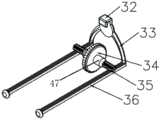
图6示出了一种实施方式的推进机构的结构示意图;FIG. 6 shows a schematic structural diagram of a propulsion mechanism of an embodiment;
图7示出了一种实施方式的手柄外壳的装配实施方案;Figure 7 shows an assembled embodiment of the handle housing of one embodiment;
图8示出了一种实施方式的套盒外壳的装配实施方案;Figure 8 shows an assembled embodiment of the kit housing of one embodiment;
图9示出了一种实施方式的套盒的右视图;Figure 9 shows a right side view of the kit of one embodiment;
图10示出了一种实施方式的手柄的右视图;Figure 10 shows a right side view of the handle of one embodiment;
图11示出了护套管体表面的刻度值;Figure 11 shows scale values on the surface of the sheath body;
图12示出了一种实施方式的护套与导管的结构示意图;Figure 12 shows a schematic structural diagram of a sheath and a catheter according to an embodiment;
图13至30示出了各种实施例的导丝头部的结构示意图;Figures 13 to 30 show structural schematic diagrams of the guide wire head of various embodiments;
以上附图中:In the above picture:
1、套盒;2、注射器;3、推进机构;4、手柄;5、通孔;6、动力源卡槽;7、动力源;8/21、螺孔;9、第三连接件;10、电池盖;11、电源;13、按钮;14、触发件;12/15/16/19、电线;17、控制器;18、旋钮;20、护套;22、软管;23、三通阀;24、顶块;25、第二连接件;26、第一连接件;27、弹性件;28、导丝;30、筒体;31、推杆;32、卡扣;33、支撑主体;34、滚轮;35、齿轮;36、齿条;29/37/38、卡槽;39、导管;40、套盒壳体;41、手柄外壳;42、滑槽;43、容纳部;44、连接本体;45、凸块;46、凸台;47、连接部。1. Set box; 2. Syringe; 3. Propulsion mechanism; 4. Handle; 5. Through hole; 6. Power source slot; 7. Power source; 8/21, screw hole; 9. Third connecting piece; 10 , battery cover; 11, power supply; 13, button; 14, trigger; 12/15/16/19, wire; 17, controller; 18, knob; 20, sheath; 22, hose; 23, tee valve; 24, top block; 25, second connecting piece; 26, first connecting piece; 27, elastic piece; 28, guide wire; 30, cylinder body; 31, push rod; 32, buckle; 33, supporting body ;34, roller; 35, gear; 36, rack; 29/37/38, card slot; 39, conduit; 40, box housing; 41, handle shell; 42, chute; 43, accommodating part; 44 , connecting the body; 45, the bump; 46, the boss; 47, the connecting part.
具体实施方式Detailed ways
下面结合附图所示的实施例对本发明作进一步描述。The present invention will be further described below with reference to the embodiments shown in the accompanying drawings.
如图1至3以及图7所示的脉管治疗装置,包括手柄4,该手柄4包括手柄外壳41、驱动机构等。如图7所示,手柄外壳41为分离的两半采用自攻丝连接固定,例如通过图3所示的螺孔8等实现手柄外壳41的固定连接。如图2和图3所示,驱动机构包括动力源7、控制器17、电源11、按钮13、触发件14、旋钮18等。The vascular treatment device shown in FIGS. 1 to 3 and FIG. 7 includes a
如图3所示,手柄外壳41内的近端上方位置形成有动力源卡槽6,动力源卡槽6可以使动力源7紧配合固定在手柄外壳41内,从而能很好的对动力源7进行固定,进而能使动力源7稳定运行及减少噪音。本实施例中,动力源7为电动机。控制器17安装在手柄外壳41内的近端下方,大概位于手柄4的握持部,控制器17与动力源7通过电线15连接;本实施例中,控制器17包括一个PCB板,该PCB板上装有单片机,单片机内部烧录程序可控制电动机的转速及开机状态的电动机的复位程序。电源11安装在手柄外壳41的远端下方,本实施例中,电源11为干电池,电源11与控制器17通过电线12连接,本实施例需要两节干电池对电动机进行供电。触发件14安装在手柄外壳41内的近端,触发件14与控制器17通过电线16连接。按钮13安装在手柄外壳41上且部分伸出手柄外壳41,按钮13的位置与触发件14的位置相对应,通过按动按钮13可以触发触发件14从而使动力源7在通电和不通电的状态转换,当动力源7通电时,即动力源7与电池相电连接能够由电池为动力源7供电,当动力源7不通电时,即动力源7与电池断开。旋钮18安装在手柄外壳41的近端底部,即握持部的底部且部分伸出手柄外壳41从而便于操作,旋钮18与控制器17通过电线19连接,该旋钮18可以无级调速,用于控制电动机转速,同时还具有开关功能,可以防止误操作。旋钮18上形成有刻度线,从而可以更加精确地控制电动机的转速,进而控制导丝28旋转的速度。As shown in FIG. 3 , a
如图1、2、4、5和8所示,套盒1包括导丝28、护套20、导管39、注射机构等。如图8所示,套盒1包括套盒壳体40,套盒壳体40为分离的两半采用自攻丝连接固定,例如通过图4所示的螺孔21等实现套盒壳体40的固定连接。如图2和图4所示,导丝28和动力源7通过连接机构相可拆卸地连接;连接机构包括第一连接件26、第二连接件25、第三连接件9和弹性件27。套盒壳体40内部近端的上下两侧分别形成有滑槽42,第一连接件26滑动设置在滑槽42内从而与套盒1相滑动连接,第一连接件26包括形成有容纳部43的连接本体44、分别形成在连接本体44的上下两端且向近端延伸的顶块24,顶块24设置在滑槽42内。每个滑槽42内设置一个弹性件27,本实施例中,弹性件27为弹簧,弹性件27的两端分别与套盒1的滑槽42的远端面以及连接本体44的远端面相抵设。手柄外壳41上形成有与两个顶块24对应设置的两个凸块45,当套盒1与手柄4相连接时,凸块45与顶块24相接触从而推动第一连接件26向远端滑动,使得第二连接件25从第一连接件26的容纳部43相脱离。As shown in Figures 1, 2, 4, 5 and 8, the
第二连接件25的远端与导丝28的近端相固定连接,第三连接件9固定安装在电动机的输出轴上,第二连接件25与第三连接件9相可拆卸地连接,当套盒1安装在手柄4上时,第二连接件25与第一连接件26相分离,且与第三连接件9相固定连接,其中,第二连接件25和第三连接件9通过卡合固定连接,从而电动机启动时能够带动导丝28绕自身轴心线旋转;当套盒1与手柄4相分离时,第二连接件25位于第一连接件26的容纳部43内,从而可以对导丝28在与手柄4配合前进行限位和固定,以使导丝28无法进行转动。The distal end of the second connecting
如图4所示,导管39与套盒壳体40相固定连接,护套20的近端与导管39的远端过盈配合且能够相对滑动而使导丝28收拢或伸出护套20;护套20和导管39的连接部47呈锥形且直径自远端向近端逐渐变大,如图12所示,从而可以保证护套20和导管39之间的密封性,术前,导丝28收拢在护套20内,即导丝28的远端不伸出护套20,从而将护套20插入血管时,导丝28不会对血管造成伤害;当护套20插入所需位置时,向近端移动护套20,使导丝28自血管伸出,此时,调整旋钮18至所需转速,按动按钮13以触发触发件14使电池为电动机供电,电动机在控制器17的控制下按照旋钮18所设定的转速转动以带动导丝28旋转,以对血管内壁造成机械损伤,从而使血管发生痉挛。本实施例中,电动机最高转速可达6000r/min。As shown in FIG. 4 , the
当护套20向近端移动至最大距离时,导丝28伸出护套20的长度为5~20mm,优选略长于10mm。When the
为了使导丝28能够更好的对血管内壁造成损伤,导丝28的远端具有弯折部,弯折部的弯折角度为30~60°,弯折部形成在距离导丝28远端部4~8mm处。本实施例中,导丝28头部的形状可以根据需要设计成多种不同的形状,例如,如图13至16所示的导丝28头部为形成有弯折角度的线丝形式;又如图17至19所示的导丝28头部成至少一个半圆形的线丝形式,再如图20至22所示的导丝28头部成至少一个菱形,当有多个菱形时,多个菱形相串联;再如图23至25所示的导丝28头部呈至少一个圆形,当有多个圆形时,多个圆形相串联;或者还可以如图26和27所示的圆弧形的线丝,如图28所示的椭圆形,如图29所示的梭子形,如图30所示的螺旋形等。In order to enable the
为了便于医护人员直观的了解护套20插入血管中的深度,护套20的表面上沿着长度方向具有30~50个刻度值,本实施例共25个刻度,相邻两个刻度值之间的距离为1厘米,如图11所示。In order to facilitate the medical staff to intuitively understand the depth of the
如图5所示,注射机构包括与套盒壳体40的上部相固定连接的三通阀23、分别与三通阀23的远端以及导管39相连通的软管22、与三通阀23的近端相连接的注射器2,软管22为软质管子,注射器2的推杆31与推进机构3相可拆卸地连接,注射器2的筒体30与手柄外壳41相卡接,注射器2的轴心线与手柄4的轴心线平行。导丝28穿设在护套20和导管39内且近端伸出导管39,使用时,通过将导丝28和护套20一同插入血管,然后向近端移动护套20使导丝28的远端伸出护套20以使导丝28旋转能够对血管内壁造成机械损伤,然后向远端移动护套20使导丝28收拢于护套20中,边回撤护套20,边通过推进机构3控制注射器2的推杆31向远端移动,以将硬化剂通过三通阀23、软管22、导管39、护套20流入血管中。As shown in FIG. 5 , the injection mechanism includes a three-
如图1和图6所示,推进机构3包括驱动件、与驱动件相连接的传动组件,传动组件与注射机构相可拆卸地连接。传动组件包括第一配合件和第二配合件,第一配合件包括一体式的支撑件以及两个齿条36;支撑件包括呈开口朝下的U型的支撑主体33、形成在支撑主体33的上端的卡扣32,卡扣32和注射器2的推杆31通过卡合固定;齿条36的近端与支撑主体33左右两端的底部相固定连接;手柄外壳41的左右两侧分别形成有内部通道的凸台46,两个齿条36分别滑动插设在该凸台46内。As shown in FIG. 1 and FIG. 6 , the
第二配合件为能够与齿条36配合运动的齿轮35,齿轮35有两个,一个齿轮35与一个齿条36相啮合从而通过齿轮35的转动带动齿条36相滑动,齿条36的滑动带动注射器2的推杆31移动以实现硬化剂的注射以及注射量和注射速度的控制。The second matching member is a
驱动件包括直径大于第二配合件的直径且表面形成有凹凸结构的滚轮34、分别与滚轮34的左右两端面相固定连接的两个连接部47,连接部47与第二配合件相固定连接,手柄外壳41上形成有通孔5,连接部47转动设置在该通孔5内且连接部47能够绕自身轴心线转动。滚轮34和连接部47形成形成阶梯状结构,以便将拇指推动滚轮34提供的动力传递给注射机构。The driving member includes a
本发明中,齿轮35和齿条36的配合以精准控制注射剂的注射量,是本领域技术人员可以通过设计或选择所需的齿轮35和齿条36来进行控制,例如,滚轮34转动一圈带动齿轮35转动一圈,齿轮35转动一圈带动齿条36前进10个齿距,对应的注射机构注射2ml硬化剂。而注射器2推进注射药物的速率与推杆31前进的速度相关,即通过滚轮34的转动速度、齿轮35和齿条36的传动比及模数多少相关,设置所需的齿轮35齿条36模数,可以精确使转动一圈通过的齿条36的模数来控制注射器2推进多少量,使药物输注更加精确。In the present invention, the cooperation of the
如图1至4、图9和图10所示,套盒1和手柄4通过卡接固定,具体结构如下:手柄外壳41的远端上部形成有用于容纳套盒1的容纳部,手柄外壳41的容纳部的两侧壁以及套盒壳体40的外侧部分别形成有能够相互卡接的卡槽37、38。为了能够使手柄4和套盒1连接的更加稳定,不易脱落,手柄外壳41的远端设置有能够挡设在用于容纳电池的电池腔的开口处的电池盖10,电池盖10的上端伸出至手柄外壳41的容纳部43,当套盒1和手柄4相连接时,电池盖10的上端深入形成在套盒壳体40的下部的卡槽29内。As shown in Figures 1 to 4, Figure 9 and Figure 10, the
本发明的使用方法:Using method of the present invention:
将套盒1安装在手柄4上,将护套20和导丝28一同插入血管,向近端移动护套20使导丝28远端伸出护套20,调节旋钮18,按动按钮13触发触发件14,使电池对电动机供电,电动机转动带动导丝28旋转以使导丝28对血管内壁造成机械损伤,从而使血管发生痉挛,使装置整体向近端移动的同时操作驱动件使注射器2推进硬化剂至血管中以起到对血管壁的固化作用,停止导丝28旋转和注射硬化剂后,向远端移动护套20使导丝28收至护套20内,边回撤护套20。本装置能够对下肢静脉曲张患者起到很好的治理作用。Install the
上述实施例只为说明本发明的技术构思及特点,其目的在于让熟悉此项技术的人士能够了解本发明的内容并据以实施,并不能以此限制本发明的保护范围。凡根据本发明精神实质所作的等效变化或修饰,都应涵盖在本发明的保护范围之内。The above-mentioned embodiments are only intended to illustrate the technical concept and characteristics of the present invention, and the purpose thereof is to enable those who are familiar with the art to understand the content of the present invention and implement them accordingly, and cannot limit the protection scope of the present invention. All equivalent changes or modifications made according to the spirit of the present invention should be included within the protection scope of the present invention.
Claims (15)
Translated fromChinesePriority Applications (1)
| Application Number | Priority Date | Filing Date | Title |
|---|---|---|---|
| CN202010452311.7ACN111514445B (en) | 2020-05-25 | 2020-05-25 | A vascular treatment device |
Applications Claiming Priority (1)
| Application Number | Priority Date | Filing Date | Title |
|---|---|---|---|
| CN202010452311.7ACN111514445B (en) | 2020-05-25 | 2020-05-25 | A vascular treatment device |
Publications (2)
| Publication Number | Publication Date |
|---|---|
| CN111514445Atrue CN111514445A (en) | 2020-08-11 |
| CN111514445B CN111514445B (en) | 2025-04-04 |
Family
ID=71905495
Family Applications (1)
| Application Number | Title | Priority Date | Filing Date |
|---|---|---|---|
| CN202010452311.7AActiveCN111514445B (en) | 2020-05-25 | 2020-05-25 | A vascular treatment device |
Country Status (1)
| Country | Link |
|---|---|
| CN (1) | CN111514445B (en) |
Cited By (3)
| Publication number | Priority date | Publication date | Assignee | Title |
|---|---|---|---|---|
| CN111938719A (en)* | 2020-08-18 | 2020-11-17 | 内蒙古工业大学 | Vessel therapeutic instrument |
| CN115177376A (en)* | 2022-06-07 | 2022-10-14 | 苏州市立普医疗科技有限公司 | Mammary gland pilot pin with roller type seal wire removes structure |
| CN116269602A (en)* | 2023-05-23 | 2023-06-23 | 苏州天鸿盛捷医疗器械有限公司 | Varicose vein intracavity closing device |
Citations (4)
| Publication number | Priority date | Publication date | Assignee | Title |
|---|---|---|---|---|
| CN101987033A (en)* | 2006-09-13 | 2011-03-23 | 瓦斯库勒英赛特有限公司 | Wire used together with device for vascular treatment |
| CN107088248A (en)* | 2017-04-10 | 2017-08-25 | 上海普益医疗器械股份有限公司 | Bivalve link rod handle pulse thrombolysis catheter pusher syringe |
| US20190290314A1 (en)* | 2016-07-03 | 2019-09-26 | Sinusafe Medical Ltd. | Medical device for treatment of a sinus and/or an ear and methods of use thereof |
| CN212214365U (en)* | 2020-05-25 | 2020-12-25 | 苏州天鸿盛捷医疗器械有限公司 | A vascular treatment device |
- 2020
- 2020-05-25CNCN202010452311.7Apatent/CN111514445B/enactiveActive
Patent Citations (4)
| Publication number | Priority date | Publication date | Assignee | Title |
|---|---|---|---|---|
| CN101987033A (en)* | 2006-09-13 | 2011-03-23 | 瓦斯库勒英赛特有限公司 | Wire used together with device for vascular treatment |
| US20190290314A1 (en)* | 2016-07-03 | 2019-09-26 | Sinusafe Medical Ltd. | Medical device for treatment of a sinus and/or an ear and methods of use thereof |
| CN107088248A (en)* | 2017-04-10 | 2017-08-25 | 上海普益医疗器械股份有限公司 | Bivalve link rod handle pulse thrombolysis catheter pusher syringe |
| CN212214365U (en)* | 2020-05-25 | 2020-12-25 | 苏州天鸿盛捷医疗器械有限公司 | A vascular treatment device |
Cited By (5)
| Publication number | Priority date | Publication date | Assignee | Title |
|---|---|---|---|---|
| CN111938719A (en)* | 2020-08-18 | 2020-11-17 | 内蒙古工业大学 | Vessel therapeutic instrument |
| CN111938719B (en)* | 2020-08-18 | 2024-06-11 | 内蒙古工业大学 | Vascular therapeutic apparatus |
| CN115177376A (en)* | 2022-06-07 | 2022-10-14 | 苏州市立普医疗科技有限公司 | Mammary gland pilot pin with roller type seal wire removes structure |
| CN116269602A (en)* | 2023-05-23 | 2023-06-23 | 苏州天鸿盛捷医疗器械有限公司 | Varicose vein intracavity closing device |
| CN116269602B (en)* | 2023-05-23 | 2023-09-01 | 苏州天鸿盛捷医疗器械有限公司 | Varicose vein intracavity closing device |
Also Published As
| Publication number | Publication date |
|---|---|
| CN111514445B (en) | 2025-04-04 |
Similar Documents
| Publication | Publication Date | Title |
|---|---|---|
| CN111514445A (en) | Vascular treatment device | |
| JP5727049B2 (en) | Disposable remote injection needle for endoscope | |
| US6159161A (en) | Microprocessor-controlled fluid dispensing apparatus | |
| EP1177003B1 (en) | A hand-piece for injection device with a retractable and rotating needle | |
| CN212214365U (en) | A vascular treatment device | |
| WO2017185981A1 (en) | Radiofrequency ablation electrode and system with local infiltration anesthesia function | |
| CA2908817C (en) | Needle insertion device | |
| US12420032B2 (en) | Needle insertion device | |
| CN114225196A (en) | Boosting device for oral local anesthesia and using method | |
| CN117224828A (en) | Bone wax applicator | |
| CN204394605U (en) | A kind of absorption injection ligation treatment device being easy to manipulate | |
| KR100687657B1 (en) | Drug injection | |
| CN113288356B (en) | Central venous puncture device | |
| KR100737441B1 (en) | Electric syringe | |
| US11559635B2 (en) | Needle insertion device | |
| KR20010081415A (en) | Apparatus for treating acne | |
| KR20250048315A (en) | segmental vascular resection | |
| CN206183339U (en) | Formula of popping out warm needle sword that to kick -back | |
| CN215309239U (en) | Central venous puncture device | |
| CN210963368U (en) | Remaining needle operated by single hand | |
| CN116271346A (en) | Syringe drive and injection device | |
| CN204698676U (en) | Adjustable radio-frequency ablation electrode needle | |
| CN219539093U (en) | Tumor drug interventional therapy device | |
| CN221845783U (en) | Be used for phimosis sacculus electric injector of dilator | |
| CN221512843U (en) | Needle feeder for acupuncture and moxibustion medical treatment |
Legal Events
| Date | Code | Title | Description |
|---|---|---|---|
| PB01 | Publication | ||
| PB01 | Publication | ||
| SE01 | Entry into force of request for substantive examination | ||
| SE01 | Entry into force of request for substantive examination | ||
| GR01 | Patent grant | ||
| GR01 | Patent grant |