Movatterモバイル変換


[0]ホーム

URL:


CN111513812A - loose body removal device - Google Patents

loose body removal device
Download PDF

Info

Publication number
CN111513812A
CN111513812ACN202010374047.XACN202010374047ACN111513812ACN 111513812 ACN111513812 ACN 111513812ACN 202010374047 ACN202010374047 ACN 202010374047ACN 111513812 ACN111513812 ACN 111513812A
Authority
CN
China
Prior art keywords
mesh
connecting rod
sliding
guide sleeve
mesh surface
Prior art date
Legal status (The legal status is an assumption and is not a legal conclusion. Google has not performed a legal analysis and makes no representation as to the accuracy of the status listed.)
Pending
Application number
CN202010374047.XA
Other languages
Chinese (zh)
Inventor
杨润松
邓毅
姜海东
李涛
Current Assignee (The listed assignees may be inaccurate. Google has not performed a legal analysis and makes no representation or warranty as to the accuracy of the list.)
ORTHOPEDIC HOSPITAL OF CHONGQING TRADITIONAL CHINESE MEDICINE
Original Assignee
ORTHOPEDIC HOSPITAL OF CHONGQING TRADITIONAL CHINESE MEDICINE
Priority date (The priority date is an assumption and is not a legal conclusion. Google has not performed a legal analysis and makes no representation as to the accuracy of the date listed.)
Filing date
Publication date
Application filed by ORTHOPEDIC HOSPITAL OF CHONGQING TRADITIONAL CHINESE MEDICINEfiledCriticalORTHOPEDIC HOSPITAL OF CHONGQING TRADITIONAL CHINESE MEDICINE
Priority to CN202010374047.XApriorityCriticalpatent/CN111513812A/en
Publication of CN111513812ApublicationCriticalpatent/CN111513812A/en
Pendinglegal-statusCriticalCurrent

Links

Images

Classifications

Landscapes

Abstract

Translated fromChinese

本发明公开了一种游离体取出装置,包括网袋、连接装置和调节手柄,所述网袋包括网面和网面骨架,所述网面边缘与网面骨架连接,所述连接装置包括导向套和滑动设置于导向套内部的连接杆,所述连接杆一端连接于网面骨架上,所述调节手柄连接于连接杆上用于驱动连接杆在导向套内滑动,连接杆滑动时带动网面骨架滑进或滑出导向套内进而调节外露于导向套外的网袋网口大小,降低了使用手术夹钳对游离体的捕捉次数,并且降低了游离体捕捉脱落和取出脱落的风险,降低了手术难度。

Figure 202010374047

The invention discloses a device for taking out loose bodies, comprising a mesh bag, a connecting device and an adjusting handle. The mesh bag includes a mesh surface and a mesh surface frame, the edge of the mesh surface is connected with the mesh surface frame, and the connection device includes a guide The sleeve and the connecting rod slidably arranged inside the guide sleeve, one end of the connecting rod is connected to the mesh surface frame, and the adjusting handle is connected to the connecting rod for driving the connecting rod to slide in the guide sleeve, and the connecting rod drives the mesh when sliding. The face frame slides into or out of the guide sleeve to adjust the mesh size of the mesh bag exposed outside the guide sleeve, which reduces the number of times of using surgical clamps to capture loose bodies, and reduces the risk of loose bodies being captured and taken out. Reduce the difficulty of surgery.

Figure 202010374047

Description

Translated fromChinese
游离体取出装置loose body removal device

技术领域technical field

本发明涉及医疗设备领域,具体涉及一种游离体取出装置。The invention relates to the field of medical equipment, in particular to a device for removing loose bodies.

背景技术Background technique

游离体在关节内活动,也称为关节鼠,在膝或肘等关节内,某些压力骨骺的凸面可在外力反复作用下发生缺血性坏死、剥脱,在关节内游离,称为剥脱性骨软骨炎(关节游离体),另外游离体上滑膜化生,可形成软骨细胞或骨细胞继续生长。现有技术中,常采用手术夹钳捕捉游离体,由于游离体表面光滑使用手术夹钳捕捉时需要多次捕捉且手术夹钳在张开和咬合时可能会造成对其他组织的破坏,并且游离体形状不一、尺寸不一和其表面光滑等因素,在手术夹钳夹持游离体取出过程中常造成游离体的脱落,增加了手术难度。Loose bodies move in joints, also known as joint mice. In joints such as knees or elbows, the convex surface of certain pressure epiphysis can undergo ischemic necrosis and exfoliation under repeated external force, and are free in joints, called exfoliation. Osteochondritis (joint loose bodies), in addition, synovial metaplasia on the loose body can form chondrocytes or bone cells to continue to grow. In the prior art, surgical clamps are often used to capture loose bodies. Due to the smooth surface of loose bodies, multiple captures are required when using surgical clamps, and the opening and occlusion of the surgical clamps may cause damage to other tissues and free Factors such as different body shapes, different sizes and smooth surfaces often cause loose bodies to fall off during the process of removing loose bodies with surgical clamps, which increases the difficulty of surgery.

因此,为解决以上问题,需要一种游离体取出装置,能够降低对游离体的捕捉次数,降低游离体脱落的风险,降低手术难度。Therefore, in order to solve the above problems, there is a need for a device for removing loose bodies, which can reduce the number of times of capturing loose bodies, reduce the risk of loose bodies falling off, and reduce the difficulty of surgery.

发明内容SUMMARY OF THE INVENTION

有鉴于此,本发明的目的是克服现有技术中的缺陷,提供游离体取出装置,能够降低对游离体的捕捉次数,降低游离体脱落的风险,降低手术难度。In view of this, the purpose of the present invention is to overcome the defects in the prior art and provide a device for removing loose bodies, which can reduce the number of times of capturing loose bodies, reduce the risk of loose bodies falling off, and reduce the difficulty of surgery.

本发明的游离体取出装置,包括网袋、连接装置和调节手柄,所述网袋包括网面和网面骨架,所述网面边缘与网面骨架连接,所述连接装置包括导向套和滑动设置于导向套内部的连接杆,所述连接杆一端连接于网面骨架上,所述调节手柄连接于连接杆上用于驱动连接杆在导向套内滑动,所述连接杆滑动时带动网面骨架滑进或滑出导向套内进而调节外露于导向套外的网袋网口大小。The loose body removal device of the present invention includes a mesh bag, a connection device and an adjustment handle, the mesh bag includes a mesh surface and a mesh surface frame, the mesh surface edge is connected to the mesh surface frame, and the connection device includes a guide sleeve and a sliding A connecting rod arranged inside the guide sleeve, one end of the connecting rod is connected to the mesh surface frame, the adjusting handle is connected to the connecting rod for driving the connecting rod to slide in the guide sleeve, and the connecting rod drives the mesh surface when sliding The skeleton slides into or out of the guide sleeve to adjust the size of the mesh opening of the mesh bag exposed outside the guide sleeve.

进一步,所述调节手柄包括壳体和滑动设置于壳体上的滑动件,所述导向套连接于壳体上,所述壳体上开设有滑槽,所述滑动件设置于滑槽内,所述连接杆一端连接滑动件,以使得滑动件带动连接杆在导向套内滑动。Further, the adjusting handle comprises a casing and a sliding member slidably arranged on the casing, the guide sleeve is connected to the casing, a sliding groove is opened on the casing, and the sliding member is arranged in the sliding groove, One end of the connecting rod is connected to the sliding piece, so that the sliding piece drives the connecting rod to slide in the guide sleeve.

进一步,所述调节手柄还包括安装于壳体上用于对滑动件进行定位的限位组件,以使得调节网袋网口大小后网口大小维持恒定。Further, the adjustment handle further includes a limit component installed on the housing for positioning the sliding member, so that the size of the mesh opening of the mesh bag is maintained constant after the mesh opening size of the mesh bag is adjusted.

进一步,所述限位组件包括弹性件、定位板和挡板,所述定位板和挡板分别连接于壳体和滑动件上,所述弹性件具有使定位板压于挡板上的弹性力,以对定位板形成定位。Further, the limiting assembly includes an elastic member, a positioning plate and a baffle, the positioning plate and the baffle are respectively connected to the housing and the sliding member, and the elastic member has an elastic force to press the positioning plate on the baffle , to position the positioning plate.

进一步,所述滑槽沿横向方向开设于壳体上,所述滑动件包括设置于滑槽内的滑动底座和驱动件,所述定位板沿纵向设置于驱动件两侧,所述挡板连接于滑槽侧壁,所述挡板位于定位板上方,所述滑动底座和驱动件通过弹性件连接,以使滑动底座下表面抵于滑槽内腔下表面,定位板上表面抵于挡板下表面。Further, the chute is opened on the casing along the lateral direction, the sliding member includes a sliding base and a driving member arranged in the sliding groove, the positioning plates are longitudinally arranged on both sides of the driving member, and the baffles are connected to each other. On the side wall of the chute, the baffle is located above the positioning plate, and the sliding base and the driving member are connected by elastic parts, so that the lower surface of the sliding base abuts against the lower surface of the inner cavity of the chute, and the upper surface of the positioning plate abuts the baffle lower surface.

进一步,所述驱动件下表面开设有放置弹性件的容纳槽,所述滑动底座上设置有与容纳槽相适配的凸台,所述凸台位于容纳槽内,所述弹性件位于容纳槽内并连接凸台和容纳槽。Further, the lower surface of the driving member is provided with a receiving groove for placing the elastic member, the sliding base is provided with a boss adapted to the receiving groove, the boss is located in the receiving groove, and the elastic member is located in the receiving groove inside and connect the boss and the receiving groove.

进一步,所述定位板和挡板结合面处设置有相配合的防滑凸起。Further, the joint surface of the positioning plate and the baffle is provided with a matching anti-slip protrusion.

进一步,所述网面边缘外套于网面骨架,以使得网面骨架张开时网面边缘在网面骨架上分散,网面骨架收拢时网面边缘在网面骨架上聚集,调节网袋网口大小。Further, the edge of the mesh surface is covered on the mesh surface frame, so that the mesh surface edge is dispersed on the mesh surface frame when the mesh surface frame is opened, and the mesh surface edge is gathered on the mesh surface frame when the mesh surface frame is closed, and the size of the mesh opening of the mesh bag is adjusted. .

进一步,所述网面骨架由一根杆体弯折形成,所述杆体两自由端对接后平行向外延伸形成连接杆。Further, the mesh surface frame is formed by bending a rod body, and the two free ends of the rod body are connected to each other and extend outward in parallel to form a connecting rod.

进一步,所述导向套内表面设置有供连接杆滑动的滑轨。Further, the inner surface of the guide sleeve is provided with a slide rail for the connecting rod to slide.

本发明的有益效果是:本发明公开的一种游离体取出装置,通过调节手柄控制连接杆在导向套内部滑动,通过连接杆调节网面骨架张开或收拢调节网袋网口大小,便于对不同尺寸的游离体进行捕捉,使用本装置可以对表面光滑游离性强、形状不一和尺寸不一的游离体进行有效捕捉,降低了使用手术夹钳对游离体的捕捉次数,并且降低了游离体捕捉脱落和取出脱落的风险,降低了手术难度。The beneficial effects of the present invention are as follows: in the device for removing loose bodies disclosed in the present invention, the connecting rod is controlled to slide inside the guide sleeve by adjusting the handle; Different sizes of loose bodies can be captured. Using this device can effectively capture loose bodies with smooth surface and strong freeness, different shapes and sizes, reducing the number of times of using surgical clamps to capture loose bodies, and reducing The risk of body capture detachment and removal detachment reduces the difficulty of surgery.

附图说明Description of drawings

下面结合附图和实施例对本发明作进一步描述:Below in conjunction with accompanying drawing and embodiment, the present invention is further described:

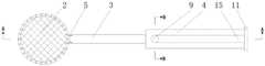
图1为本发明的结构示意图;Fig. 1 is the structural representation of the present invention;

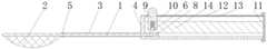
图2为本发明A-A向截面连接杆网袋骨架张开时的结构示意图;Fig. 2 is the structural schematic diagram of the present invention when the cross-section connecting rod mesh bag skeleton is opened to A-A;

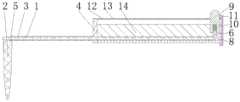
图3为本发明A-A向截面连接杆网袋骨架收拢时的结构示意图;3 is a schematic structural diagram of the present invention when A-A is folded to the cross-section connecting rod mesh bag skeleton;

图4为本发明导向套3的结构示意图;Fig. 4 is the structural representation of theguide sleeve 3 of the present invention;

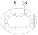
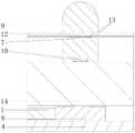
图5为本发明B-B向截面的结构示意图;Fig. 5 is the structural representation of the B-B cross section of the present invention;

图6为本发明B-B向截面的C-C向结构示意图。FIG. 6 is a schematic view of the C-C direction structure of the B-B direction section of the present invention.

具体实施方式Detailed ways

图1为本发明的结构示意图;图2为本发明A-A向截面连接杆网袋骨架张开时的结构示意图;图3为本发明A-A向截面连接杆网袋骨架收拢时的结构示意图;图4为本发明导向套3的结构示意图;图5为本发明B-B向截面的结构示意图;图6为本发明B-B向截面的C-C向结构示意图本实施例中,所述横向为壳体4长度方向,所述纵向为壳体4宽度方向。如图所示,本实施例中的游离体取出装置包括网袋、连接装置和调节手柄,所述网袋包括网面2和网面骨架,所述网面2边缘与网面骨架连接,所述连接装置包括导向套3和滑动设置于导向套3内部的连接杆1,所述连接杆1一端连接于网面骨架上,所述调节手柄连接于连接杆上用于驱动连接杆在导向套内滑动,所述连接杆滑动时带动网面骨架滑进或滑出导向套内进而调节外露于导向套外的网袋网口大小。所述网面2为具有一定形变能力的柔性材料制成,所述网面骨架由具有一定支撑能力的刚性材料制成,所述网面骨架滑出对应网袋网口由小口径调节至大口径,即网面骨架张开,此时网袋呈开口状态便于对游离体的捕捉,所述网面骨架滑进对应网袋网口由大口径调节至小口径,即网面骨架收拢,此时网袋呈封口状态将捕捉到的游离体限制于网袋内,所述网面2边缘与骨架连接减少了多余网面2的存在,提高了网面2利用率,同时也降低了多余网面2对捕捉游离体时的影响。所述网面骨架随着连接杆1在导向套3内的滑动,相对应的调节网袋网口大小,所述网面2边缘可以与网面骨架固定连接,当网面骨架收拢时,连接杆1将网袋拉入至导向套3内,此时网袋呈封口状态,当网面骨架张开时,连接杆1将拉入至导向套3内的网袋推出,此时网袋呈开口状态,但是此种调节会导致位于网面骨架和导向套3之间的网面2在多次张开或收拢时使得网面2受损严重,需要经常更换,网面2利用率低,在网面骨架张开或收拢时还容易将网面2卡于导向套3内导致网面骨架难以张开或收拢,并且在卡于导向套3内时如果用力过大会导致网面2撕裂等情况,影响对游离体的捕捉,严重时还会对病患者造成伤害,或者其他如将网面2,部分固定连接网面骨架,在连接杆1滑动时同样可以起到对网袋网口大小控制的其他手段,在此不再赘述。在进行游离体捕捉时,将封口状态的网袋伸入至病患处,通过调节手柄调节连接杆1在导向套3内滑动,控制网面骨架张开使网袋呈开口状态,对病患者体内尺寸不一的游离体进行捕捉,捕捉后再通过调节手柄调节连接杆1,控制网面骨架收拢使网袋重新处于封口状态,此时捕捉到的游离体被封闭于网袋内,将网袋拉出病患处即可将病患处存在的游离体取出,在此过程中,网袋均以较小口径伸入及拉出病患处,降低对病患处及其它周边组织的破坏,采用本装置便于对不同尺寸的游离体进行捕捉,可以对表面光滑游离性强、形状不一和尺寸不一的游离体进行有效捕捉,降低了使用手术夹钳对游离体的捕捉次数,并且降低了游离体捕捉脱落和取出脱落的风险,降低了手术难度,所述导向套3可以设置成套筒状、也可设置成沿某一方向盘旋的盘旋状、或者设计成折线状等其他结构,所述连接杆1与导向套3适形设置于导向套3内部,以使得连接杆1可在导向套3内滑动带动网面骨架,调节网袋网口大小,在此不再赘述。Fig. 1 is the structural representation of the present invention; Fig. 2 is the structural representation of the present invention when A-A is opened to the cross-section connecting rod mesh bag skeleton; Fig. 3 is the structural representation of the present invention when the cross-sectional connecting rod mesh bag skeleton is folded; Fig. 4 is the Figure 5 is a schematic structural diagram of the B-B section of the present invention; Figure 6 is a C-C structural schematic diagram of the B-B section of the present invention. In this embodiment, the lateral direction is the length direction of thecasing 4, and the The longitudinal direction is the width direction of thecasing 4 . As shown in the figure, the free body removal device in this embodiment includes a mesh bag, a connecting device and an adjustment handle, the mesh bag includes amesh surface 2 and a mesh surface frame, and the edge of themesh surface 2 is connected with the mesh surface frame, so The connecting device includes aguide sleeve 3 and a connectingrod 1 slidably arranged inside theguide sleeve 3. One end of the connectingrod 1 is connected to the mesh frame, and the adjusting handle is connected to the connecting rod for driving the connecting rod to the guide sleeve. When sliding inside, the connecting rod drives the mesh frame to slide into or out of the guide sleeve to adjust the size of the mesh opening of the mesh bag exposed outside the guide sleeve. Themesh surface 2 is made of a flexible material with a certain deformability, and the mesh surface frame is made of a rigid material with a certain support capacity. The caliber, that is, the mesh surface frame is opened. At this time, the mesh bag is in an open state to facilitate the capture of loose bodies. The mesh surface frame is slid into the corresponding mesh bag. When the mesh bag is in a sealed state, the captured loose bodies are confined in the mesh bag. The connection between the edge of themesh surface 2 and the skeleton reduces the existence of theredundant mesh surface 2, improves the utilization rate of themesh surface 2, and reduces the excess mesh. The effect offace 2 on capturing loose bodies. The mesh skeleton follows the sliding of the connectingrod 1 in theguide sleeve 3, and adjusts the mesh size of the mesh bag correspondingly. The edge of themesh 2 can be fixedly connected with the mesh skeleton. When the mesh skeleton is closed, the mesh is connected. Therod 1 pulls the mesh bag into theguide sleeve 3, and the mesh bag is in a sealed state at this time. When the mesh surface frame is opened, the connectingrod 1 will push out the mesh bag pulled into theguide sleeve 3, and the mesh bag is in an open state at this time. However, this adjustment will cause themesh surface 2 located between the mesh surface skeleton and theguide sleeve 3 to be seriously damaged when themesh surface 2 is opened or closed for many times, and needs to be replaced frequently, the utilization rate of themesh surface 2 is low, and themesh surface 2 When the surface frame is opened or folded, it is easy to clamp themesh surface 2 in theguide sleeve 3, which makes the mesh surface frame difficult to open or close, and if the force is too strong when stuck in the guide sleeve 3, themesh surface 2 will be torn, etc. , affecting the capture of loose bodies, and even causing harm to patients in severe cases, or other such as fixing themesh surface 2 to the mesh surface skeleton, when the connectingrod 1 slides, it can also control the mesh size of the mesh bag. other means, which will not be repeated here. When the loose body is captured, the mesh bag in the sealed state is extended to the patient, and the connectingrod 1 is adjusted to slide in theguide sleeve 3 by adjusting the handle, and the mesh surface frame is controlled to open so that the mesh bag is in an open state. The loose bodies of different sizes in the body are captured, and after the capture, the connectingrod 1 is adjusted by adjusting the handle, and the mesh frame is controlled to be retracted so that the mesh bag is in a sealed state again. The loose body existing in the patient can be taken out by pulling the bag out of the patient. During this process, the mesh bag is inserted into and pulled out of the patient with a small diameter to reduce the damage to the patient and other surrounding tissues. , the use of this device is convenient to capture loose bodies of different sizes, and can effectively capture loose bodies with smooth surfaces and strong freeness, different shapes and sizes, reducing the number of times of using surgical clamps to capture loose bodies, and The risk of loose body catching and falling off and taking out and falling off is reduced, and the difficulty of the operation is reduced. Theguide sleeve 3 can be set in a sleeve shape, can also be set in a spiral shape that rotates along a certain steering wheel, or is designed in other structures such as a broken line. , the connectingrod 1 and theguide sleeve 3 are conformally arranged inside theguide sleeve 3, so that the connectingrod 1 can slide in theguide sleeve 3 to drive the mesh frame to adjust the mesh size of the mesh bag, which will not be repeated here.

本实施例中,所述调节手柄包括壳体4和滑动设置于壳体4上的滑动件,所述导向套3连接于壳体4上,所述壳体4上开设有滑槽15,所述滑动件设置于滑槽15内,所述连接杆1一端连接滑动件,以使得滑动件带动连接杆1在导向套3内滑动。所述调节手柄还可设置成带有相适配插拔结构的插销和插座,使得插销与连接杆1一端连接,通过调节插销在插座上的不同位置,调节连接杆1在导向套3内滑动,或者设置电动推杆等其他结构,带动连接杆1在导向套3内滑动,以调节网袋网口大小,在此不再赘述,采用滑动设置于壳体4上的滑动件和壳体4所构成的调节手柄,仅通过调节滑动件即可达到对网袋网口大小的调节,并且其结构简单、操作方便、造价低廉,所述滑槽15可以开设于壳体4表面,也可以开设于壳体4内部,均可达到将连接于连接杆1一端的滑动件设置于滑槽15内,带动连接杆1在导向套3内滑动,当然所述壳体4上有供连接杆1穿过的通孔,所述导向套3与壳体4胶结,当然也可采用螺钉连接、铆接等连接方式,在此不再赘述。In this embodiment, the adjusting handle includes acasing 4 and a sliding member slidably arranged on thecasing 4 , theguide sleeve 3 is connected to thecasing 4 , and thecasing 4 is provided with asliding groove 15 , so The sliding member is arranged in thechute 15 , and one end of the connectingrod 1 is connected to the sliding member, so that the sliding member drives the connectingrod 1 to slide in theguide sleeve 3 . The adjustment handle can also be configured as a plug and a socket with a matching plug-in structure, so that the plug is connected to one end of the connectingrod 1, and the connectingrod 1 can be adjusted to slide in theguide sleeve 3 by adjusting the different positions of the plug on the socket. , or other structures such as electric push rods are provided to drive the connectingrod 1 to slide in theguide sleeve 3 to adjust the size of the mesh opening of the mesh bag. The formed adjustment handle can adjust the size of the mesh opening of the mesh bag only by adjusting the sliding member, and has a simple structure, convenient operation and low cost. Inside thehousing 4 , the sliding piece connected to one end of the connectingrod 1 can be arranged in thechute 15 to drive the connectingrod 1 to slide in theguide sleeve 3 . Theguide sleeve 3 is glued with thehousing 4 through the through hole through, and of course, connection methods such as screw connection and riveting can also be used, which will not be repeated here.

本实施例中,所述调节手柄还包括安装于壳体上用于对滑动件进行定位的限位组件,以使得调节网袋网口大小后网口大小维持恒定。设置限位组件的目的在于在壳体4上调节滑动件时,可以对滑动件所处位置进行定位,从而更好的确定网袋网口大小,降低首次捕捉未成功,频繁操作调节手柄的操作步骤,提高捕捉游离体的效率。In this embodiment, the adjusting handle further includes a limiting component mounted on the housing for positioning the sliding member, so that the size of the mesh opening of the mesh bag is maintained constant after the mesh opening size of the mesh bag is adjusted. The purpose of setting the limit component is to locate the position of the sliding piece when adjusting the sliding piece on thehousing 4, so as to better determine the size of the mesh opening of the mesh bag, and reduce the failure of the first capture and the frequent manipulation of the adjustment handle. step to improve the efficiency of capturing free bodies.

本实施例中,所述限位组件包括弹性件10、定位板7和挡板12,所述定位板7和挡板12分别连接于壳体4和滑动件上,所述弹性件10具有使定位板7压于挡板12上的弹性力,以对定位板7形成定位。所述限位组件还可以设置成定位销与定位槽相适配的结构,所述定位槽为开设于壳体4上若干个通孔和开设于滑动件上的与开设于壳体4上若干个通孔相适配的槽,采用在定位槽内插拔的定位销对滑动件所处位置进行定位,所述定位销和定位槽相适配为现有技术,在此不再赘述,或者通过构件摩擦定位、磁力定位或者其他的定位方式,实现调节网袋网口大小后网口大小维持恒定,在此不再赘述,采用弹性件10、定位板7和挡板12的限位组件,结构简单,操作方便,并且造价低廉,所述定位板7和挡板12相适配即为定位板7与挡板12在结构上相适配,可以设置成在二者结合面处相配合的凸起,也将挡板12和定位板7设置成相互嵌入的结构,均可实现对滑动件进行定位,在此不再赘述。In this embodiment, the limiting assembly includes anelastic member 10, a positioning plate 7 and abaffle 12. The positioning plate 7 and thebaffle 12 are respectively connected to thehousing 4 and the sliding member. Theelastic member 10 has a The elastic force of the positioning plate 7 pressing on thebaffle plate 12 is used to form the positioning of the positioning plate 7 . The position-limiting assembly can also be configured as a structure in which the positioning pins are matched with the positioning grooves. The position of the sliding piece is positioned by using a positioning pin inserted and withdrawn in the positioning slot. The matching of the positioning pin and the positioning slot is the prior art, which will not be repeated here, or through the component Friction positioning, magnetic positioning or other positioning methods can be used to adjust the size of the mesh opening of the mesh bag and maintain a constant mesh size, which will not be repeated here. Theelastic member 10, the positioning plate 7 and thebaffle 12 are used to limit the components, and the structure is simple. , the operation is convenient, and the cost is low. The matching of the positioning plate 7 and thebaffle 12 means that the positioning plate 7 and thebaffle 12 are structurally matched, and can be set as a protrusion that matches at the joint surface of the two. , thebaffle plate 12 and the positioning plate 7 are also arranged to be embedded in each other, so that the sliding member can be positioned, which will not be repeated here.

本实施例中,所述滑槽15沿横向方向开设于壳体4上,所述滑动件包括设置于滑槽15内的滑动底座8和驱动件9,所述定位板7沿纵向设置于驱动件9两侧,所述挡板12连接于滑槽15侧壁,所述挡板12位于定位板7上方,所述滑动底座8和驱动件9通过弹性件10连接,以使滑动底座8下表面抵于滑槽15内腔下表面,定位板7上表面抵于挡板12下表面。所述滑槽15尾部设置堵头11封闭,所述滑槽15尾部即为横向上远离网袋的壳体4一端,所述堵头11和壳体4可拆卸连接,设置成尾部开口的滑槽15和可拆卸封闭滑槽15的堵头11,便于对滑槽15内部构件进行安装,同时也便于对内部构件进行更换,大大提高了装置的使用寿命和零部件的利用率,所述定位板7为两块设置于驱动件9两侧,所述挡板12为两块设置于滑槽15侧壁,与定位板7呈对应关系,使得挡板12和滑槽15合围成容纳滑动件的腔室,驱动件9和滑动底座8通过弹性件10设置于滑槽15内,弹性件10具有使定位板7上表面与挡板12下表面相靠近的弹性力,即对滑动件所处位置进行定位,实现调节网袋网口大小后网口大小维持恒定,在定位板7上表面与挡板12下表面相互远离时,驱动件9可以带动滑动底座8在滑槽15内滑动,以实现滑动件沿横向方向在壳体4上滑动调节网袋网口大小,限位组件的设置实现了定位板7和挡板12相互远离时,滑动件可在壳体4上滑动,使滑动件具有良好的操控性,定位板7和挡板12相互靠近时,滑动件固定于壳体4上,使滑动件具有良好的定位效果,起到提高调节手柄的使用性能,便于对调节手柄的灵活操控,所述连接杆1一端连接于滑动底座8,此处连接为胶结,当然也可螺纹连接或螺钉连接等其他连接方式,在此不再赘述,所述滑动底座8上开设有使连接杆1一端插入至滑动底座8内部的胶结槽,进一步提高连接杆1一端与滑动底座8的稳定连接,降低连接杆1在调节手柄使用时发生脱落、晃动等影响装置操作性的情况,所述定位板7和驱动件9一体成型制作,当然所述定位板7还可以胶结或螺钉连接等方式设置于驱动件9上,在此不再赘述,所述壳体4和挡板12一体成型制作,当然所述挡板12板还可以胶结或螺钉连接等方式设置于壳体4上,在此不再赘述,所述驱动件9位于滑槽15开口处有向滑槽15开口方向延伸的驱动件凸起,所述驱动件凸起凸出壳体4,所述驱动件凸起为顶部带有半球凸起的柱状结构,便于操作人员对驱动件9的操控。In this embodiment, thechute 15 is provided on thecasing 4 in the lateral direction, the sliding member includes a slidingbase 8 and a drivingmember 9 disposed in thechute 15 , and the positioning plate 7 is longitudinally disposed on the drivingmember 9 . 9, thebaffle 12 is connected to the side wall of thechute 15, thebaffle 12 is located above the positioning plate 7, the slidingbase 8 and the drivingmember 9 are connected by theelastic member 10, so that the slidingbase 8 goes down The surface abuts the lower surface of the inner cavity of thechute 15 , and the upper surface of the positioning plate 7 abuts the lower surface of thebaffle 12 . The tail of thechute 15 is provided with aplug 11 to close, and the tail of thechute 15 is the end of thecasing 4 that is laterally away from the mesh bag. Theslot 15 and thedetachable plug 11 that closes thechute 15 facilitate the installation of the internal components of thechute 15 and the replacement of the internal components, which greatly improves the service life of the device and the utilization rate of components. Two plates 7 are arranged on both sides of the drivingmember 9, and twobaffle plates 12 are arranged on the side walls of thechute 15, and are in a corresponding relationship with the positioning plate 7, so that thebaffle plate 12 and thechute 15 are enclosed to accommodate the sliding parts. The drivingmember 9 and the slidingbase 8 are arranged in thechute 15 through theelastic member 10, and theelastic member 10 has the elastic force to make the upper surface of the positioning plate 7 and the lower surface of thebaffle plate 12 close The size of the mesh opening is kept constant after adjusting the mesh size of the mesh bag. When the upper surface of the positioning plate 7 and the lower surface of thebaffle 12 are far away from each other, the drivingmember 9 can drive the slidingbase 8 to slide in thechute 15 to The sliding piece can be slid on thecasing 4 along the lateral direction to adjust the size of the mesh opening of the mesh bag. The setting of the limit component realizes that when the positioning plate 7 and thebaffle 12 are far away from each other, the sliding piece can slide on thecasing 4, so that the sliding piece can slide on thecasing 4. It has good controllability. When the positioning plate 7 and thebaffle 12 are close to each other, the sliding member is fixed on thehousing 4, so that the sliding member has a good positioning effect, which improves the use performance of the adjustment handle and facilitates the flexibility of the adjustment handle. For control, one end of the connectingrod 1 is connected to the slidingbase 8, and the connection is glued here. Of course, other connection methods such as threaded connection or screw connection are also possible, which will not be repeated here. 1 One end is inserted into the glue groove inside the slidingbase 8, which further improves the stable connection between one end of the connectingrod 1 and the slidingbase 8, and reduces the situation that the connectingrod 1 falls off and shakes when the adjustment handle is in use, which affects the operability of the device. The plate 7 and the drivingmember 9 are integrally formed. Of course, the positioning plate 7 can also be set on the drivingmember 9 by means of gluing or screw connection, which will not be repeated here. Thecasing 4 and thebaffle 12 are integrally formed. Of course, thebaffle plate 12 can also be glued or screwed on thecasing 4 , which will not be repeated here. Protrusion, the driving member protrusion protrudes out of thehousing 4 , and the driving member protrusion is a columnar structure with a hemispherical protrusion on the top, which is convenient for the operator to control the drivingmember 9 .

本实施例中,所述驱动件9下表面开设有放置弹性件10的容纳槽,所述滑动底座8上设置有与容纳槽相适配的凸台6,所述凸台6位于容纳槽内,所述弹性件10位于容纳槽内并连接凸台6和容纳槽。所述弹性件10也可直接设置于驱动件9和滑动底座8之间,但此种连接方式容易出现弹性件10脱离驱动件9和滑动底座8,或出现驱动件9在带动滑动底座8时出现弹性件10打滑的现象,影响本装置的造作性,影响对游离体的捕捉,严重时还会影响本装置的正常使用或者对患者病患处带来损伤,带来不必要的麻烦,所述容纳槽起到对弹性件10限位的作用,所述凸台6将弹性件10压于容纳槽内则是进一步将弹性件10稳定设置于驱动件9和滑动底座8之间,提高对本装置的操控性,降低手术时的风险,提高对游离体的捕捉效率,降低滑动件在使用时出现弹性件10失效的情况,所述弹性件10失效包括弹性件10脱离驱动件9和滑动底座8、弹性件10在驱动件9和滑动底座88间位置发生打滑及窜动等情况,在此不再赘述。所述滑动底座8为圆盘状结构,所述凸台6设置于滑动底座8中心位置与容纳槽相适配,所述滑动底座8和凸台6一体成型制作,当然所述凸台6还可以胶结或螺钉连接等方式设置于滑动底座8上,在此不再赘述,所述弹性件10为弹簧,具有一定的形变效果及弹性力,且能实现对滑动件的灵活使用,所述弹性件10还可以为具有一定形变效果和弹性力的橡胶等材料或其他弹性元件,在此不再赘述。In this embodiment, the lower surface of the drivingmember 9 is provided with a receiving groove for placing theelastic member 10 , and the slidingbase 8 is provided with aboss 6 which is adapted to the receiving groove, and theboss 6 is located in the receiving groove. , theelastic member 10 is located in the accommodating groove and connects theboss 6 and the accommodating groove. Theelastic member 10 can also be directly arranged between the drivingmember 9 and the slidingbase 8, but this connection method is prone to theelastic member 10 being separated from the drivingmember 9 and the slidingbase 8, or when the drivingmember 9 drives the slidingbase 8. The slippage of theelastic member 10 occurs, which affects the manufacturability of the device, affects the capture of loose bodies, and even affects the normal use of the device or causes damage to the patient's disease in severe cases, causing unnecessary trouble. The accommodating groove plays a role in limiting the position of theelastic member 10, and theboss 6 presses theelastic member 10 into the accommodating groove to further stably arrange theelastic member 10 between the drivingmember 9 and the slidingbase 8, thereby improving the performance of theelastic member 10. The maneuverability of the device reduces the risk during surgery, improves the capture efficiency of loose bodies, and reduces the failure of theelastic member 10 during use of the sliding member. Theelastic member 10 failure includes theelastic member 10 being separated from the drivingmember 9 and the slidingbase 8. Theelastic member 10 slips and moves between the drivingmember 9 and the sliding base 88, which will not be repeated here. The slidingbase 8 is a disc-shaped structure, and theboss 6 is arranged at the center of the slidingbase 8 to match the accommodating groove. The slidingbase 8 and theboss 6 are integrally formed. Of course, theboss 6 is also Theelastic member 10 can be arranged on the slidingbase 8 by means of cementation or screw connection, which will not be repeated here. Theelastic member 10 is a spring, which has a certain deformation effect and elastic force, and can realize the flexible use of the sliding member. Themember 10 may also be a material such as rubber or other elastic elements with certain deformation effect and elastic force, which will not be repeated here.

本实施例中,所述定位板7和挡板12结合面处设置有相配合的防滑凸起。所述定位板7上表面和挡板12下表面均设置有相互配合的定位齿13,以使得定位板7上表面抵于挡板12下表面时滑动底座8下表面抵于滑槽15底面,对滑动件进行定位,维持网袋网口大小,所述定位齿13为挡板12与定位板7向接触面延伸出的齿状凸出结构,所述齿状突出结构相互啮合,实现对对网袋网口大小的精确控制,同时也进一步提高了滑动件固定时的稳定性,降低出现滑动件操控失灵产生网袋网口大小变化的现象或者不能固定网袋网口大小的现象,便于医护人员对游离体的捕捉和取出,所述防滑凸起还可设置成圆滑的半球状凸起,以相互咬合的方式设置或者设置成其他结构,以起到进一步对滑动设置于壳体4上的滑动件进行精确的定位,在此不再赘述。In this embodiment, matching anti-slip protrusions are provided at the joint surfaces of the positioning plate 7 and thebaffle 12 . The upper surface of the positioning plate 7 and the lower surface of thebaffle plate 12 are provided withpositioning teeth 13 that cooperate with each other, so that when the upper surface of the positioning plate 7 abuts against the lower surface of thebaffle plate 12, the lower surface of the slidingbase 8 abuts on the bottom surface of thechute 15. Position the sliding member to maintain the size of the mesh opening of the mesh bag. The positioningteeth 13 are tooth-like protruding structures extending from thebaffle 12 and the positioning plate 7 to the contact surface. The precise control of the mesh size of the mesh bag also further improves the stability of the sliding member when it is fixed, and reduces the phenomenon that the sliding member fails to control the size of the mesh bag or the mesh bag cannot be fixed, which is convenient for medical care. For the capture and removal of loose bodies by personnel, the anti-skid protrusions can also be arranged as smooth hemispherical protrusions, which are arranged in a mutually engaging manner or are arranged in other structures, so as to further prevent the sliding mechanism provided on thehousing 4. The sliding member performs precise positioning, which is not repeated here.

本实施例中,所述网面2边缘外套于网面骨架,以使得网面骨架张开时网面2边缘在网面骨架上分散,网面骨架收拢时网面2边缘在网面骨架上聚集,调节网袋网口大小。所述网面2边缘与导向套3通过两个套环5连接,当然也可采用胶结、铆接等连接方式,在此不再赘述,所述网面2边缘外套于网面骨架与导向套3一端固定连接,使网面2边缘与网面骨架形成滑动连接,当网面骨架收拢时,连接杆1将网面骨架拉入至导向套3内,外套于网面骨架的网面2边缘在网面骨架上聚拢,此时网袋呈封口状态,当网面骨架张开时,连接杆1将拉入至导向套3内的网面骨架推出,外套于网面骨架的网面2边缘在网面骨架上分散,此时网袋呈开口状态,采用此类设计不仅提高网面2利用率,而且不会产生网面2撕裂、网面2与导向套3相影响等情况,提高了对游离体的捕捉效率。In this embodiment, the edges of themesh surface 2 are covered on the mesh surface skeleton, so that when the mesh surface skeleton is opened, themesh surface 2 edges are scattered on the mesh surface skeleton, and when the mesh surface skeleton is closed, themesh surface 2 edges are gathered on the mesh surface skeleton. Adjust the size of the mesh opening of the mesh bag. The edge of themesh surface 2 and theguide sleeve 3 are connected by twocollars 5, of course, bonding, riveting and other connection methods can also be used, which will not be repeated here, the edge of themesh surface 2 is covered on the mesh surface skeleton and theguide sleeve 3. One end is fixedly connected to form a sliding connection between the edge of themesh surface 2 and the mesh surface skeleton. When the mesh surface skeleton is closed, the connectingrod 1 pulls the mesh surface skeleton into theguide sleeve 3, and the edge of themesh surface 2 that covers the mesh surface skeleton. The mesh frame is gathered on the mesh surface, and the mesh bag is in a sealed state at this time. When the mesh surface frame is opened, the connectingrod 1 will push out the mesh surface frame pulled into theguide sleeve 3. The skeleton is dispersed, and the mesh bag is in an open state at this time. This kind of design not only improves the utilization rate of themesh surface 2, but also does not cause the tearing of themesh surface 2 and the influence of themesh surface 2 and theguide sleeve 3. body capture efficiency.

本实施例中,所述网面骨架由一根杆体弯折形成,所述杆体两自由端对接后平行向外延伸形成连接杆1。所述网面骨架由一根杆体弯折形成轮廓呈封闭的圆环状结构,所述向外延伸即为远离圆环状结构向壳体4方向延伸,也就是说所述连接杆1为两根且两根连接杆1同时对网面骨架进行调节,所述连接杆1在导向套3内部沿纵向方向并列设置,相较于单根连接杆1结构稳定性有所提升,并且单根连接杆1结构在调节网面骨架张开或收拢时,必然会导致网面骨架一侧由于频繁弯折的缘故导致网面骨架的提前失效,影响网面骨架的使用寿命,而两根连接杆1分别连接于一根杆体的两自由端端则解决了此类问题,并且可以使得网面骨架同时张开或收拢,使得网袋网口在调节时呈圆形,便于对游离体的捕捉,所述网面骨架和连接杆1均采用直径不超过0.7cm的钢丝制成,优选为0.5cm,在保证屈服强度的情况下保证连接杆1和网面骨架的使用强度及寿命,所述网面骨架和杆体还可由塑料或其他材料制成,在此不再赘述,所述网面骨架和连接杆1一体成型制造,构成一根由连接滑动底座8处开始延伸贯穿导向套3和网面2边缘并迂回导向套3再次连接至滑动底座8的杆体,当然所述网面骨架还可由胶结、螺钉连接等方式连接,在此不再赘述,所述网面2采用尼龙材料制成,所述网面2上网格口径不超过0.25cm2,优选为0.01cm2,所述网袋网口张开最大直径为2.0cm,优选为2.0cm,所述网面骨架收拢时,由网面骨架到网面2最低点的距离不超过2.0cm,优选为2.0cm,采用此规格设计网袋是为了满足一般情况下对游离体快速和准确的捕捉,当然,所述网袋可根据实际情况选择网面2网格直径大小和网袋网口直径大小,所述连接杆1也可根据实际情况控制网袋网口张开大小及网面骨架到网面2最低点的高度,所述网面2还可由塑料或其他材料制成,在此不再赘述。In this embodiment, the mesh surface frame is formed by bending a rod body, and the two free ends of the rod body are connected to each other and extend parallel to the outside to form a connectingrod 1 . The mesh skeleton is formed by bending a rod to form a closed annular structure. One and two connectingrods 1 adjust the mesh frame at the same time. The connectingrods 1 are arranged side by side in the longitudinal direction inside theguide sleeve 3. Compared with the single connectingrod 1, the structural stability is improved, and the single connectingrod 1 is connected When therod 1 structure adjusts the opening or closing of the mesh frame, it will inevitably lead to the premature failure of the mesh frame due to frequent bending on one side of the mesh frame, affecting the service life of the mesh frame, and the two connectingrods 1 Connecting to the two free ends of a rod body solves such problems, and can make the mesh skeleton open or close at the same time, so that the mesh opening of the mesh bag is round when adjusted, which is convenient for the capture of loose bodies. The mesh surface frame and the connectingrod 1 are all made of steel wires with a diameter of no more than 0.7cm, preferably 0.5cm, to ensure the service strength and life of the connectingrod 1 and the mesh surface frame under the condition of ensuring the yield strength. The skeleton and the rod body can also be made of plastic or other materials, which will not be repeated here. The mesh surface skeleton and the connectingrod 1 are integrally formed, forming a connecting slidingbase 8 that extends through theguide sleeve 3 and the edge of themesh surface 2. And thedetour guide sleeve 3 is connected to the rod body of the slidingbase 8 again. Of course, the mesh surface frame can also be connected by bonding, screw connection, etc., which will not be repeated here. Themesh surface 2 is made of nylon material, and themesh surface 2 is made of nylon material. The mesh diameter on thesurface 2 is not more than 0.25cm2 , preferably 0.01cm2 , and the maximum diameter of the mesh opening of the mesh bag is 2.0cm, preferably 2.0cm. The distance from the lowest point of theface 2 is not more than 2.0cm, preferably 2.0cm. The mesh bag is designed with this specification to meet the fast and accurate capture of loose bodies in general. Of course, the mesh bag can choose the mesh surface according to the actual situation. 2. The diameter of the mesh and the diameter of the mesh opening of the mesh bag. The connectingrod 1 can also control the opening size of the mesh opening of the mesh bag and the height of the mesh surface frame to the lowest point of themesh surface 2 according to the actual situation. It can be made of plastic or other materials, which will not be repeated here.

本实施例中,所述导向套3内表面设置有供连接杆1滑动的滑轨,所述滑轨即为与连接杆1外表面相适配的凸起16,当连接杆1在导向套3内滑动时,连接杆1会在导向套3内部以较小的摩擦力移动,较小的摩擦力会导致连接杆1在导向套3内部产生过快的移动,从而不利于使用者在操控本装置时对网袋网口大小的可控调节,为了提高连接杆1在导向套3内滑动时的良好操控性能,本装置在导向套3内表面增设凸起16增大导向套3内表面与连接杆1外表面的摩擦力,降低出现连接杆1在导向套3内部过快滑动的现象,起到对连接杆1滑动速度可控调节的作用,进一步提高对网袋网口大小的精确控制,所述凸起16在导向套3内表面均匀布置,相邻凸起16间有便于连接杆1滑动的空隙,避免凸起16过多导致连接杆1滑动困难的情况,所述凸起16与导向套3一体成型采用橡胶材料制造,当然也可采用塑料等材料制造,在此不再赘述。In this embodiment, the inner surface of theguide sleeve 3 is provided with a sliding rail for the connectingrod 1 to slide, and the sliding rail is aprotrusion 16 adapted to the outer surface of the connectingrod 1. When sliding inside, the connectingrod 1 will move with a small frictional force inside theguide sleeve 3, and the small frictional force will cause the connectingrod 1 to move too fast inside theguide sleeve 3, which is not conducive to the user's operation of the The controllable adjustment of the mesh size of the mesh bag during the installation, in order to improve the good control performance of the connectingrod 1 when sliding in theguide sleeve 3, the device adds aprotrusion 16 on the inner surface of theguide sleeve 3 to increase the inner surface of theguide sleeve 3. The frictional force on the outer surface of the connectingrod 1 reduces the phenomenon that the connectingrod 1 slides too fast inside theguide sleeve 3, plays the role of controllable adjustment of the sliding speed of the connectingrod 1, and further improves the precise control of the mesh size of the mesh bag , theprotrusions 16 are evenly arranged on the inner surface of theguide sleeve 3, and there are gaps between theadjacent protrusions 16 to facilitate the sliding of the connectingrod 1 to avoid the situation that the connectingrod 1 is difficult to slide due to toomany protrusions 16. Theprotrusions 16 The integral molding with theguide sleeve 3 is made of a rubber material, of course, it can also be made of a material such as plastic, which will not be repeated here.

本实施例中,所述滑槽15侧壁沿纵向方向向槽内相对突出形成导向台14,所述驱动件9和滑动底座8均设置于导向台14之间,所述导向台14靠近驱动件9侧面一面与驱动件9和滑动底座8之间留有一定间隙相适配,以使得导向台14有对驱动件9和滑动底座8沿横向方向导向的作用,同时也沿纵向方向对驱动件9和滑动底座8进行限位,所述导向台14靠近滑动底座8一面与滑动底座8上表面留有一定间隙相适配,对滑动底座8沿高度方向限位,以使得滑动底座8沿既定轨迹运动,进一步提高本装置的安全性能,所述定位板7与挡板12相互远离时,所述导向台14靠近定位板7一面可作为定位板7沿横向运动的承台,所述所述导向台14靠近驱动件9侧面一面还可沿高度方向对驱动件9进行导向,进一步提高滑动件沿横向运动时的稳定性,提高本装置的安全性,导向台14的设置降低了滑动件在使用时出现晃动、滑动不稳等情况影响本装置的使用,在此不再赘述。In this embodiment, the side wall of thechute 15 relatively protrudes into the slot along the longitudinal direction to form a guide table 14 , the drivingmember 9 and the slidingbase 8 are both arranged between the guide tables 14 , and the guide table 14 is close to the drive The side surface of themember 9 is matched with a certain gap between the drivingmember 9 and the slidingbase 8, so that the guide table 14 can guide the drivingmember 9 and the slidingbase 8 in the lateral direction, and also guide the drivingmember 9 and the slidingbase 8 in the longitudinal direction.Part 9 and the slidingbase 8 to limit the position, the guide table 14 is close to the slidingbase 8 and has a certain gap on the upper surface of the slidingbase 8 to match, and the slidingbase 8 is limited in the height direction, so that the slidingbase 8 is along the height direction. The predetermined trajectory movement further improves the safety performance of the device. When the positioning plate 7 and thebaffle plate 12 are far away from each other, the side of the guide table 14 close to the positioning plate 7 can be used as a bearing platform for the positioning plate 7 to move laterally. Said guide table 14 can also guide the drivingelement 9 along the height direction on the side close to the side of the drivingelement 9, which further improves the stability of the sliding element when it moves laterally and improves the safety of the device. The setting of the guiding table 14 reduces the sliding element. Shaking, unstable sliding, etc. during use will affect the use of the device, and will not be repeated here.

最后说明的是,以上实施例仅用以说明本发明的技术方案而非限制,尽管参照较佳实施例对本发明进行了详细说明,本领域的普通技术人员应当理解,可以对本发明的技术方案进行修改或者等同替换,而不脱离本发明技术方案的宗旨和范围,其均应涵盖在本发明的权利要求范围当中。Finally, it should be noted that the above embodiments are only used to illustrate the technical solutions of the present invention and not to limit them. Although the present invention has been described in detail with reference to the preferred embodiments, those of ordinary skill in the art should understand that the technical solutions of the present invention can be Modifications or equivalent substitutions without departing from the spirit and scope of the technical solutions of the present invention should be included in the scope of the claims of the present invention.

Claims (10)

Translated fromChinese
1.一种游离体取出装置,其特征在于:包括网袋、连接装置和调节手柄,所述网袋包括网面和网面骨架,所述网面边缘与网面骨架连接,所述连接装置包括导向套和滑动设置于导向套内部的连接杆,所述连接杆一端连接于网面骨架上,所述调节手柄连接于连接杆上用于驱动连接杆在导向套内滑动,所述连接杆滑动时带动网面骨架滑进或滑出导向套内进而调节外露于导向套外的网袋网口大小。1. A device for taking out loose bodies, characterized in that: comprising a mesh bag, a connecting device and an adjustment handle, the mesh bag comprises a mesh surface and a mesh surface skeleton, and the edge of the mesh surface is connected with the mesh surface skeleton, and the connecting device It includes a guide sleeve and a connecting rod slidably arranged inside the guide sleeve. One end of the connecting rod is connected to the mesh frame, and the adjusting handle is connected to the connecting rod for driving the connecting rod to slide in the guide sleeve. The connecting rod When sliding, it drives the mesh surface frame to slide into or out of the guide sleeve to adjust the mesh size of the mesh bag exposed outside the guide sleeve.2.根据权利要求1所述的游离体取出装置,其特征在于:所述调节手柄包括壳体和滑动设置于壳体上的滑动件,所述导向套连接于壳体上,所述壳体上开设有滑槽,所述滑动件设置于滑槽内,所述连接杆一端连接滑动件,以使得滑动件带动连接杆在导向套内滑动。2 . The device for removing loose bodies according to claim 1 , wherein the adjusting handle comprises a casing and a sliding member slidably arranged on the casing, the guide sleeve is connected to the casing, and the casing A sliding groove is opened on the upper part, the sliding piece is arranged in the sliding groove, and one end of the connecting rod is connected with the sliding piece, so that the sliding piece drives the connecting rod to slide in the guide sleeve.3.根据权利要求2所述的游离体取出装置,其特征在于:所述调节手柄还包括安装于壳体上用于对滑动件进行定位的限位组件,以使得调节网袋网口大小后网口大小维持恒定。3 . The free body removal device according to claim 2 , wherein the adjusting handle further comprises a limit component mounted on the housing for positioning the sliding member, so that after adjusting the size of the mesh opening of the mesh bag, 3 . The size of the network port remains constant.4.根据权利要求3所述的游离体取出装置,其特征在于:所述限位组件包括弹性件、定位板和挡板,所述定位板和挡板分别连接于壳体和滑动件上,所述弹性件具有使定位板压于挡板上的弹性力,以对定位板形成定位。4 . The device for removing loose bodies according to claim 3 , wherein the limiting component comprises an elastic member, a positioning plate and a baffle, and the positioning plate and the baffle are respectively connected to the casing and the sliding member, 4 . The elastic member has an elastic force for pressing the positioning plate on the baffle plate, so as to form a positioning for the positioning plate.5.根据权利要求4所述的游离体取出装置,其特征在于:所述滑槽沿横向方向开设于壳体上,所述滑动件包括设置于滑槽内的滑动底座和驱动件,所述定位板沿纵向设置于驱动件两侧,所述挡板连接于滑槽侧壁,所述挡板位于定位板上方,所述滑动底座和驱动件通过弹性件连接,以使滑动底座下表面抵于滑槽内腔下表面,定位板上表面抵于挡板下表面。5 . The device for removing loose bodies according to claim 4 , wherein the chute is opened on the casing along the lateral direction, the sliding member comprises a sliding base and a driving member arranged in the chute, and the The positioning plates are longitudinally arranged on both sides of the driving member, the baffles are connected to the side walls of the chute, the baffles are located above the positioning plates, and the sliding base and the driving member are connected by elastic members, so that the lower surface of the sliding base On the lower surface of the inner cavity of the chute, the upper surface of the positioning plate abuts the lower surface of the baffle plate.6.根据权利要求5所述的游离体取出装置,其特征在于:所述驱动件下表面开设有放置弹性件的容纳槽,所述滑动底座上设置有与容纳槽相适配的凸台,所述凸台位于容纳槽内,所述弹性件位于容纳槽内并连接凸台和容纳槽。6 . The free body removal device according to claim 5 , wherein the lower surface of the driving member is provided with a receiving groove for placing the elastic member, and the sliding base is provided with a boss adapted to the receiving groove, 7 . The boss is located in the accommodating groove, and the elastic piece is located in the accommodating groove and connects the boss and the accommodating groove.7.根据权利要求5所述的游离体取出装置,其特征在于:所述定位板和挡板结合面处设置有相配合的防滑凸起。7 . The device for removing loose bodies according to claim 5 , wherein a matching anti-slip protrusion is provided on the joint surface of the positioning plate and the baffle. 8 .8.根据权利要求1所述的游离体取出装置,其特征在于:所述网面边缘外套于网面骨架,以使得网面骨架张开时网面边缘在网面骨架上分散,网面骨架收拢时网面边缘在网面骨架上聚集,调节网袋网口大小。8 . The device for removing loose bodies according to claim 1 , wherein the edge of the mesh surface is wrapped around the mesh surface frame, so that the mesh surface edge is dispersed on the mesh surface frame when the mesh surface frame is opened, and when the mesh surface frame is closed. 9 . The edges of the mesh surface are gathered on the mesh surface frame to adjust the size of the mesh opening of the mesh bag.9.根据权利要求8所述的游离体取出装置,其特征在于:所述网面骨架由一根杆体弯折形成,所述杆体两自由端对接后平行向外延伸形成连接杆。9 . The free body removal device according to claim 8 , wherein the mesh frame is formed by bending a rod body, and the two free ends of the rod body are connected to each other and extend parallel to the outside to form a connecting rod. 10 .10.根据权利要求9所述的游离体取出装置,其特征在于:所述导向套内表面设置有供连接杆滑动的滑轨。10 . The loose body removal device according to claim 9 , wherein the inner surface of the guide sleeve is provided with a slide rail for the connecting rod to slide. 11 .
CN202010374047.XA2020-05-062020-05-06 loose body removal devicePendingCN111513812A (en)

Priority Applications (1)

Application NumberPriority DateFiling DateTitle
CN202010374047.XACN111513812A (en)2020-05-062020-05-06 loose body removal device

Applications Claiming Priority (1)

Application NumberPriority DateFiling DateTitle
CN202010374047.XACN111513812A (en)2020-05-062020-05-06 loose body removal device

Publications (1)

Publication NumberPublication Date
CN111513812Atrue CN111513812A (en)2020-08-11

Family

ID=71908486

Family Applications (1)

Application NumberTitlePriority DateFiling Date
CN202010374047.XAPendingCN111513812A (en)2020-05-062020-05-06 loose body removal device

Country Status (1)

CountryLink
CN (1)CN111513812A (en)

Citations (6)

* Cited by examiner, † Cited by third party
Publication numberPriority datePublication dateAssigneeTitle
US5490859A (en)*1992-11-131996-02-13Scimed Life Systems, Inc.Expandable intravascular occlusion material removal devices and methods of use
US5741271A (en)*1991-11-051998-04-21Nakao; Naomi L.Surgical retrieval assembly and associated method
US5782840A (en)*1997-02-141998-07-21Wilk & Nakao Medical Technology, Inc.Snare cauterization surgical instrument assembly and method of manufacture
US20070016225A1 (en)*2005-07-152007-01-18Nakao Naomi LEndoscope retrieval instrument assembly
CN102056554A (en)*2008-06-092011-05-11百乐仕医疗器械有限公司Medical treatment tool for tubular organs
CN209474727U (en)*2018-12-102019-10-11谢慧琴 A portable stone collector

Patent Citations (6)

* Cited by examiner, † Cited by third party
Publication numberPriority datePublication dateAssigneeTitle
US5741271A (en)*1991-11-051998-04-21Nakao; Naomi L.Surgical retrieval assembly and associated method
US5490859A (en)*1992-11-131996-02-13Scimed Life Systems, Inc.Expandable intravascular occlusion material removal devices and methods of use
US5782840A (en)*1997-02-141998-07-21Wilk & Nakao Medical Technology, Inc.Snare cauterization surgical instrument assembly and method of manufacture
US20070016225A1 (en)*2005-07-152007-01-18Nakao Naomi LEndoscope retrieval instrument assembly
CN102056554A (en)*2008-06-092011-05-11百乐仕医疗器械有限公司Medical treatment tool for tubular organs
CN209474727U (en)*2018-12-102019-10-11谢慧琴 A portable stone collector

Similar Documents

PublicationPublication DateTitle
CN111513812A (en) loose body removal device
CN113951974B (en) A Multi-angle Reversing Straw Curette Used in Otolaryngology
CN112098698B (en) A meter loading and unwinding device
CN220833829U (en) A urinary catheter removal syringe
CN219290275U (en)Gastrointestinal fluid pressure reducing device
CN209422329U (en)A kind of Orthopaedic nursing dressing auxiliary device
CN113274030B (en)Anti-interference electrocardiogram examination device
CN213345832U (en)Ear-nose-throat foreign body extractor
CN209826959U (en)Interstitial tumor resection device integrating stripping, resection and recovery
CN211050707U (en) Storage device for suction tube
CN221691083U (en)Eye speculum for ophthalmic clinic
CN219070675U (en)Needle finder for nursing in operating room
CN223452216U (en)Process information recording device
CN209213791U (en) A portable harness device for installing LED street lamps
CN219213303U (en) A two-piece split opener
CN216876991U (en) A medical care cart
CN216934301U (en) An insulin needle separation device
CN209544790U (en)A kind of automatic liquid pressing tongs
CN216702858U (en)Nursing tray with adjustable size
CN221866080U (en)Dental oral water suction tube easy to fix
CN221865596U (en) Adjustable flexible endoscope
CN211862195U (en)Medical science is filing cabinet for chronic disease management
CN210698355U (en)Anorectal surgery incision drainage device
CN218064153U (en)Intelligent card read-write machine
CN222467708U (en)Infusion bag positioning device

Legal Events

DateCodeTitleDescription
PB01Publication
PB01Publication
SE01Entry into force of request for substantive examination
RJ01Rejection of invention patent application after publication

Application publication date:20200811


[8]ページ先頭

©2009-2025 Movatter.jp