CN111511455B - Honeycomb body and particle filter comprising a honeycomb body - Google Patents
Honeycomb body and particle filter comprising a honeycomb bodyDownload PDFInfo
- Publication number
- CN111511455B CN111511455BCN201880084303.2ACN201880084303ACN111511455BCN 111511455 BCN111511455 BCN 111511455BCN 201880084303 ACN201880084303 ACN 201880084303ACN 111511455 BCN111511455 BCN 111511455B
- Authority
- CN
- China
- Prior art keywords
- filter
- equal
- honeycomb
- porous
- layer
- Prior art date
- Legal status (The legal status is an assumption and is not a legal conclusion. Google has not performed a legal analysis and makes no representation as to the accuracy of the status listed.)
- Active
Links
Images


Classifications
- B—PERFORMING OPERATIONS; TRANSPORTING
- B01—PHYSICAL OR CHEMICAL PROCESSES OR APPARATUS IN GENERAL
- B01D—SEPARATION
- B01D46/00—Filters or filtering processes specially modified for separating dispersed particles from gases or vapours
- B01D46/24—Particle separators, e.g. dust precipitators, using rigid hollow filter bodies
- B01D46/2403—Particle separators, e.g. dust precipitators, using rigid hollow filter bodies characterised by the physical shape or structure of the filtering element
- B01D46/2418—Honeycomb filters
- B01D46/2451—Honeycomb filters characterized by the geometrical structure, shape, pattern or configuration or parameters related to the geometry of the structure
- B01D46/2474—Honeycomb filters characterized by the geometrical structure, shape, pattern or configuration or parameters related to the geometry of the structure of the walls along the length of the honeycomb
- B—PERFORMING OPERATIONS; TRANSPORTING
- B01—PHYSICAL OR CHEMICAL PROCESSES OR APPARATUS IN GENERAL
- B01D—SEPARATION
- B01D39/00—Filtering material for liquid or gaseous fluids
- B01D39/14—Other self-supporting filtering material ; Other filtering material
- B01D39/20—Other self-supporting filtering material ; Other filtering material of inorganic material, e.g. asbestos paper, metallic filtering material of non-woven wires
- B01D39/2068—Other inorganic materials, e.g. ceramics
- B—PERFORMING OPERATIONS; TRANSPORTING
- B01—PHYSICAL OR CHEMICAL PROCESSES OR APPARATUS IN GENERAL
- B01D—SEPARATION
- B01D46/00—Filters or filtering processes specially modified for separating dispersed particles from gases or vapours
- B01D46/0001—Making filtering elements
- B—PERFORMING OPERATIONS; TRANSPORTING
- B01—PHYSICAL OR CHEMICAL PROCESSES OR APPARATUS IN GENERAL
- B01D—SEPARATION
- B01D46/00—Filters or filtering processes specially modified for separating dispersed particles from gases or vapours
- B01D46/24—Particle separators, e.g. dust precipitators, using rigid hollow filter bodies
- B01D46/2403—Particle separators, e.g. dust precipitators, using rigid hollow filter bodies characterised by the physical shape or structure of the filtering element
- B01D46/2418—Honeycomb filters
- B01D46/2425—Honeycomb filters characterized by parameters related to the physical properties of the honeycomb structure material
- B01D46/2429—Honeycomb filters characterized by parameters related to the physical properties of the honeycomb structure material of the honeycomb walls or cells
- B—PERFORMING OPERATIONS; TRANSPORTING
- B01—PHYSICAL OR CHEMICAL PROCESSES OR APPARATUS IN GENERAL
- B01D—SEPARATION
- B01D46/00—Filters or filtering processes specially modified for separating dispersed particles from gases or vapours
- B01D46/24—Particle separators, e.g. dust precipitators, using rigid hollow filter bodies
- B01D46/2403—Particle separators, e.g. dust precipitators, using rigid hollow filter bodies characterised by the physical shape or structure of the filtering element
- B01D46/2418—Honeycomb filters
- B01D46/2425—Honeycomb filters characterized by parameters related to the physical properties of the honeycomb structure material
- B01D46/24491—Porosity
- B—PERFORMING OPERATIONS; TRANSPORTING
- B01—PHYSICAL OR CHEMICAL PROCESSES OR APPARATUS IN GENERAL
- B01D—SEPARATION
- B01D46/00—Filters or filtering processes specially modified for separating dispersed particles from gases or vapours
- B01D46/24—Particle separators, e.g. dust precipitators, using rigid hollow filter bodies
- B01D46/2403—Particle separators, e.g. dust precipitators, using rigid hollow filter bodies characterised by the physical shape or structure of the filtering element
- B01D46/2418—Honeycomb filters
- B01D46/2425—Honeycomb filters characterized by parameters related to the physical properties of the honeycomb structure material
- B01D46/24492—Pore diameter
- B—PERFORMING OPERATIONS; TRANSPORTING
- B01—PHYSICAL OR CHEMICAL PROCESSES OR APPARATUS IN GENERAL
- B01D—SEPARATION
- B01D46/00—Filters or filtering processes specially modified for separating dispersed particles from gases or vapours
- B01D46/24—Particle separators, e.g. dust precipitators, using rigid hollow filter bodies
- B01D46/2403—Particle separators, e.g. dust precipitators, using rigid hollow filter bodies characterised by the physical shape or structure of the filtering element
- B01D46/2418—Honeycomb filters
- B01D46/2451—Honeycomb filters characterized by the geometrical structure, shape, pattern or configuration or parameters related to the geometry of the structure
- B01D46/2482—Thickness, height, width, length or diameter
- B—PERFORMING OPERATIONS; TRANSPORTING
- B01—PHYSICAL OR CHEMICAL PROCESSES OR APPARATUS IN GENERAL
- B01D—SEPARATION
- B01D53/00—Separation of gases or vapours; Recovering vapours of volatile solvents from gases; Chemical or biological purification of waste gases, e.g. engine exhaust gases, smoke, fumes, flue gases, aerosols
- B01D53/34—Chemical or biological purification of waste gases
- B01D53/74—General processes for purification of waste gases; Apparatus or devices specially adapted therefor
- B01D53/86—Catalytic processes
- B01D53/88—Handling or mounting catalysts
- B01D53/885—Devices in general for catalytic purification of waste gases
- C—CHEMISTRY; METALLURGY
- C04—CEMENTS; CONCRETE; ARTIFICIAL STONE; CERAMICS; REFRACTORIES
- C04B—LIME, MAGNESIA; SLAG; CEMENTS; COMPOSITIONS THEREOF, e.g. MORTARS, CONCRETE OR LIKE BUILDING MATERIALS; ARTIFICIAL STONE; CERAMICS; REFRACTORIES; TREATMENT OF NATURAL STONE
- C04B38/00—Porous mortars, concrete, artificial stone or ceramic ware; Preparation thereof
- C04B38/0006—Honeycomb structures
- C04B38/0009—Honeycomb structures characterised by features relating to the cell walls, e.g. wall thickness or distribution of pores in the walls
- F—MECHANICAL ENGINEERING; LIGHTING; HEATING; WEAPONS; BLASTING
- F01—MACHINES OR ENGINES IN GENERAL; ENGINE PLANTS IN GENERAL; STEAM ENGINES
- F01N—GAS-FLOW SILENCERS OR EXHAUST APPARATUS FOR MACHINES OR ENGINES IN GENERAL; GAS-FLOW SILENCERS OR EXHAUST APPARATUS FOR INTERNAL-COMBUSTION ENGINES
- F01N3/00—Exhaust or silencing apparatus having means for purifying, rendering innocuous, or otherwise treating exhaust
- F01N3/02—Exhaust or silencing apparatus having means for purifying, rendering innocuous, or otherwise treating exhaust for cooling, or for removing solid constituents of, exhaust
- F01N3/021—Exhaust or silencing apparatus having means for purifying, rendering innocuous, or otherwise treating exhaust for cooling, or for removing solid constituents of, exhaust by means of filters
- F01N3/022—Exhaust or silencing apparatus having means for purifying, rendering innocuous, or otherwise treating exhaust for cooling, or for removing solid constituents of, exhaust by means of filters characterised by specially adapted filtering structure, e.g. honeycomb, mesh or fibrous
- B—PERFORMING OPERATIONS; TRANSPORTING
- B01—PHYSICAL OR CHEMICAL PROCESSES OR APPARATUS IN GENERAL
- B01D—SEPARATION
- B01D2239/00—Aspects relating to filtering material for liquid or gaseous fluids
- B01D2239/10—Filtering material manufacturing
- B—PERFORMING OPERATIONS; TRANSPORTING
- B01—PHYSICAL OR CHEMICAL PROCESSES OR APPARATUS IN GENERAL
- B01D—SEPARATION
- B01D2255/00—Catalysts
- B01D2255/90—Physical characteristics of catalysts
- B01D2255/92—Dimensions
- B—PERFORMING OPERATIONS; TRANSPORTING
- B01—PHYSICAL OR CHEMICAL PROCESSES OR APPARATUS IN GENERAL
- B01D—SEPARATION
- B01D2273/00—Operation of filters specially adapted for separating dispersed particles from gases or vapours
- B01D2273/18—Testing of filters, filter elements, sealings
- C—CHEMISTRY; METALLURGY
- C04—CEMENTS; CONCRETE; ARTIFICIAL STONE; CERAMICS; REFRACTORIES
- C04B—LIME, MAGNESIA; SLAG; CEMENTS; COMPOSITIONS THEREOF, e.g. MORTARS, CONCRETE OR LIKE BUILDING MATERIALS; ARTIFICIAL STONE; CERAMICS; REFRACTORIES; TREATMENT OF NATURAL STONE
- C04B2111/00—Mortars, concrete or artificial stone or mixtures to prepare them, characterised by specific function, property or use
- C04B2111/00474—Uses not provided for elsewhere in C04B2111/00
- C04B2111/00793—Uses not provided for elsewhere in C04B2111/00 as filters or diaphragms
- F—MECHANICAL ENGINEERING; LIGHTING; HEATING; WEAPONS; BLASTING
- F01—MACHINES OR ENGINES IN GENERAL; ENGINE PLANTS IN GENERAL; STEAM ENGINES
- F01N—GAS-FLOW SILENCERS OR EXHAUST APPARATUS FOR MACHINES OR ENGINES IN GENERAL; GAS-FLOW SILENCERS OR EXHAUST APPARATUS FOR INTERNAL-COMBUSTION ENGINES
- F01N11/00—Monitoring or diagnostic devices for exhaust-gas treatment apparatus
- F—MECHANICAL ENGINEERING; LIGHTING; HEATING; WEAPONS; BLASTING
- F01—MACHINES OR ENGINES IN GENERAL; ENGINE PLANTS IN GENERAL; STEAM ENGINES
- F01N—GAS-FLOW SILENCERS OR EXHAUST APPARATUS FOR MACHINES OR ENGINES IN GENERAL; GAS-FLOW SILENCERS OR EXHAUST APPARATUS FOR INTERNAL-COMBUSTION ENGINES
- F01N2550/00—Monitoring or diagnosing the deterioration of exhaust systems
- F—MECHANICAL ENGINEERING; LIGHTING; HEATING; WEAPONS; BLASTING
- F01—MACHINES OR ENGINES IN GENERAL; ENGINE PLANTS IN GENERAL; STEAM ENGINES
- F01N—GAS-FLOW SILENCERS OR EXHAUST APPARATUS FOR MACHINES OR ENGINES IN GENERAL; GAS-FLOW SILENCERS OR EXHAUST APPARATUS FOR INTERNAL-COMBUSTION ENGINES
- F01N2560/00—Exhaust systems with means for detecting or measuring exhaust gas components or characteristics
- F01N2560/05—Exhaust systems with means for detecting or measuring exhaust gas components or characteristics the means being a particulate sensor
- G—PHYSICS
- G01—MEASURING; TESTING
- G01N—INVESTIGATING OR ANALYSING MATERIALS BY DETERMINING THEIR CHEMICAL OR PHYSICAL PROPERTIES
- G01N15/00—Investigating characteristics of particles; Investigating permeability, pore-volume or surface-area of porous materials
- G01N15/08—Investigating permeability, pore-volume, or surface area of porous materials
- G01N2015/084—Testing filters
Landscapes
- Chemical & Material Sciences (AREA)
- Physics & Mathematics (AREA)
- Geometry (AREA)
- Chemical Kinetics & Catalysis (AREA)
- Engineering & Computer Science (AREA)
- Ceramic Engineering (AREA)
- Environmental & Geological Engineering (AREA)
- Materials Engineering (AREA)
- Structural Engineering (AREA)
- Organic Chemistry (AREA)
- Analytical Chemistry (AREA)
- Biomedical Technology (AREA)
- Health & Medical Sciences (AREA)
- General Chemical & Material Sciences (AREA)
- Oil, Petroleum & Natural Gas (AREA)
- Geology (AREA)
- Life Sciences & Earth Sciences (AREA)
- Inorganic Chemistry (AREA)
- Combustion & Propulsion (AREA)
- Mechanical Engineering (AREA)
- General Engineering & Computer Science (AREA)
- Filtering Materials (AREA)
- Filtering Of Dispersed Particles In Gases (AREA)
- Exhaust Gas After Treatment (AREA)
- Processes For Solid Components From Exhaust (AREA)
Abstract
Description
Translated fromChinese背景技术Background Art
本申请要求2017年10月31日提交的美国临时专利申请序列号62/579,601以及2018年8月31日提交的美国临时专利申请序列号62/725,978的优先权权益,本文以其内容作为基础并将其全文通过引用结合入本文。This application claims the benefit of priority to U.S. Provisional Patent Application Serial No. 62/579,601 filed on October 31, 2017 and U.S. Provisional Patent Application Serial No. 62/725,978 filed on August 31, 2018, the contents of which are relied upon and incorporated herein by reference in their entirety.
技术领域Technical Field
本说明书涉及蜂窝体、包含蜂窝体的颗粒过滤器以及此类蜂窝体和颗粒过滤器的制造方法。The present description relates to a honeycomb body, a particle filter comprising a honeycomb body, and a method for producing such a honeycomb body and a particle filter.
背景技术Background Art
陶瓷壁流式过滤器被用于从流体废气流(例如,从内燃机排气)去除颗粒。例子包括:用于从柴油发动机尾气去除颗粒的陶瓷烟炱过滤器;以及用于从汽油发动机尾气去除颗粒的汽油颗粒过滤器(GPF)。对于壁流式过滤器,待过滤的尾气进入入口孔道并通过孔道壁经由出口通道离开过滤器,当气体发生横穿然后离开过滤器时,颗粒被俘获在入口孔道壁上或者壁中。颗粒可以包括烟炱和/或灰。在长期暴露于发动机尾气之后,通常会在过滤器内部发生灰和/或烟炱的积聚。Ceramic wall-flow filters are used to remove particles from a fluid exhaust stream (e.g., from an internal combustion engine exhaust). Examples include: ceramic soot filters for removing particles from diesel engine exhaust; and gasoline particulate filters (GPF) for removing particles from gasoline engine exhaust. For wall-flow filters, the exhaust gas to be filtered enters the inlet channel and exits the filter through the channel walls via the outlet channel, and particles are captured on or in the inlet channel walls as the gas traverses and then exits the filter. The particles can include soot and/or ash. After long-term exposure to engine exhaust, accumulation of ash and/or soot typically occurs inside the filter.
发明内容Summary of the invention
本公开内容的方面属于陶瓷制品,例如蜂窝体和颗粒过滤器,以及它们的制造和使用方法。在一些实施方式中,颗粒过滤器包括蜂窝体,所述蜂窝体包括多孔壁的多孔陶瓷蜂窝结构,所述多孔壁包括壁表面,所述壁表面包含过滤材料沉积物,该表面限定了多个内部通道(通道)。多孔壁包括多孔底壁(base wall)以及布置在多孔底壁中的一个或多个上的过滤材料沉积物,其中,多孔壁形成了通道。过滤材料沉积物包括一种或多种无机材料,例如一种或多种陶瓷或耐火材料。过滤材料沉积物布置在壁上从而提供了蜂窝体的过滤效率强化。在一些实施方式中,至少在从清洁状态或者从再生状态使用蜂窝体时,强化了过滤效率,例如当蜂窝体在蜂窝体内侧没有积聚或者基本没有积聚灰或烟炱时,例如当蜂窝体是新的或者经过再生去除全部或者基本上全部的灰和/或烟炱时。然后,在长期暴露于发动机尾气之后(例如,在将蜂窝体长期用作过滤器之后),通常会在蜂窝体的通道内侧发生灰和/或烟炱的明显积聚。在一个或多个实施方式中,过滤材料沉积物是耐用的,例如,具有耐用性,例如,耐受高的气体或空气流动通过颗粒过滤器,几乎没有或者没有过滤性能的劣化。Aspects of the present disclosure pertain to ceramic articles, such as honeycombs and particulate filters, and methods of making and using the same. In some embodiments, a particulate filter comprises a honeycomb comprising a porous ceramic honeycomb structure having a porous wall, the porous wall comprising a wall surface, the wall surface comprising a filter material deposit, the surface defining a plurality of internal channels (channels). The porous wall comprises a porous base wall and a filter material deposit disposed on one or more of the porous base walls, wherein the porous wall forms a channel. The filter material deposit comprises one or more inorganic materials, such as one or more ceramic or refractory materials. The filter material deposit is disposed on the wall to provide enhanced filtration efficiency of the honeycomb. In some embodiments, the filtration efficiency is enhanced at least when the honeycomb is used from a clean state or from a regenerated state, such as when the honeycomb has no or substantially no ash or soot accumulated inside the honeycomb, such as when the honeycomb is new or has been regenerated to remove all or substantially all of the ash and/or soot. Then, after long-term exposure to engine exhaust (e.g., after long-term use of the honeycomb as a filter), significant accumulation of ash and/or soot typically occurs inside the channels of the honeycomb. In one or more embodiments, the filter material deposit is durable, e.g., having durability, e.g., withstanding high gas or air flows through the particulate filter with little or no degradation in filtration performance.
在一个或多个实施方式中,在蜂窝结构的一个或多个壁的基本整个表面或者甚至整个表面存在过滤材料沉积物。因此,在一些实施方式中,面朝通道且因此限定了通道的壁的外表面包括沉积物。在一些实施方式中,一些壁的一些表面部分不含沉积物,因而一些壁可以包括不含沉积物的表面部分。在一些实施方式中,一部分的过滤材料沉积物布置在多孔底壁部分中,例如,部分延伸进入底壁部分中的指状物或根状物的形式。在一些实施方式中,在多孔底壁的孔中也存在过滤材料沉积物,但是没有渗透底壁的整个厚度;因此,底壁的至少一些内部部分不含任何沉积物。在一些实施方式中,在壁的表面处存在作为集成膜或层的沉积物,以及在一些实施方式中,是集成连续层,从而使得蜂窝结构的壁的至少一些表面包括膜或层;在这些实施方式的一些中,沉积物存在于限定了一个或多个通道的所有的壁的整个表面上,例如,那些底壁被过滤材料沉积物完全覆盖或者基本上完全覆盖;在这些实施方式的其他一些中,仅在限定了一个或多个通道的壁的底壁的一部分表面上存在过滤材料沉积物。层或膜是多孔的,优选是高度多孔的,从而允许气体流动通过层,以及底壁也是多孔的,从而气体可以流动通过多孔壁。在一些实施方式中,在所述一个或多个壁的至少部分表面上或者整个表面上存在作为连续涂层的层或膜。在一些优选实施方式中,颗粒过滤器的蜂窝体的仅一部分的孔道壁提供有过滤材料沉积物,例如仅对应于堵塞蜂窝体的入口流动通道的孔道。In one or more embodiments, there is a filter material deposit on substantially the entire surface or even the entire surface of one or more walls of the honeycomb structure. Thus, in some embodiments, the outer surface of the wall facing the channel and thus defining the channel includes a deposit. In some embodiments, some surface portions of some walls are free of deposits, and thus some walls may include surface portions free of deposits. In some embodiments, a portion of the filter material deposit is arranged in the porous bottom wall portion, for example, in the form of fingers or roots that partially extend into the bottom wall portion. In some embodiments, there is also a filter material deposit in the pores of the porous bottom wall, but without penetrating the entire thickness of the bottom wall; thus, at least some internal portions of the bottom wall do not contain any deposits. In some embodiments, there is a deposit as an integrated film or layer at the surface of the wall, and in some embodiments, an integrated continuous layer, so that at least some surfaces of the walls of the honeycomb structure include a film or layer; in some of these embodiments, the deposit is present on the entire surface of all walls defining one or more channels, for example, those bottom walls are completely covered or substantially completely covered by the filter material deposit; in some other of these embodiments, there is a filter material deposit only on a portion of the surface of the bottom wall of the wall defining one or more channels. The layer or membrane is porous, preferably highly porous, so as to allow gas to flow through the layer, and the bottom wall is also porous so that gas can flow through the porous wall. In some embodiments, the layer or membrane is present as a continuous coating on at least part of the surface of the one or more walls or on the entire surface. In some preferred embodiments, only a portion of the cell walls of the honeycomb body of the particle filter are provided with filter material deposits, for example only the cells corresponding to the inlet flow channels of the honeycomb body that are blocked.
在一个方面中,过滤材料沉积物包括火焰沉积的过滤材料。在一些实施方式中,蜂窝结构的多孔壁包括作为集成层或膜存在的沉积物,其构成一个或多个通道的壁的至少一部分表面,以及在这些实施方式的一些中,一个或多个壁的至少部分表面或者整个表面包括连续层。In one aspect, the filter material deposit comprises a flame deposited filter material. In some embodiments, the porous wall of the honeycomb structure comprises a deposit present as an integrated layer or film, which constitutes at least a portion of the surface of the wall of one or more channels, and in some of these embodiments, at least a portion of the surface or the entire surface of one or more walls comprises a continuous layer.
在一些实施方式中,蜂窝结构的一个或多个壁的表面包括过滤材料沉积物的多个离散区域。In some embodiments, the surface of one or more walls of the honeycomb structure includes a plurality of discrete areas of filter material deposits.
在一些实施方式中,过滤材料沉积物部分阻挡住了多孔底壁的一些孔的一部分,同时仍然允许气体流动通过壁。In some embodiments, the filter material deposit partially blocks a portion of some of the pores of the porous bottom wall while still allowing gas to flow through the wall.
在本文所揭示的一组实施方式中,蜂窝体包括蜂窝结构,其包括:第一端、第二端以及从第一端延伸到第二端的多个壁。所述多个壁包括多个多孔壁。多孔壁包括多孔底壁。至少一些多孔壁的表面还包括过滤材料沉积物。所述多个壁限定了从第一端延伸到第二端的多个通道。一些通道在第一端处或者靠近第一端处被堵塞住,而余下通道中的一些在第二端处或者靠近第二端处被堵塞住,从而提供了壁流式过滤器流动路径,其构成了如下气体流动:从第一端进入入口通道,穿过一部分的多孔壁,以及通过出口通道离开并离开第二端。在一些实施方式中,过滤材料沉积物存在于限定了入口通道中的一个或多个的壁上;在这些实施方式的一些中,过滤材料沉积物不存在于限定了出口通道的壁上。In one set of embodiments disclosed herein, a honeycomb body comprises a honeycomb structure comprising: a first end, a second end, and a plurality of walls extending from the first end to the second end. The plurality of walls comprises a plurality of porous walls. The porous walls comprise a porous bottom wall. The surfaces of at least some of the porous walls also comprise filter material deposits. The plurality of walls define a plurality of channels extending from the first end to the second end. Some of the channels are blocked at or near the first end, while some of the remaining channels are blocked at or near the second end, thereby providing a wall-flow filter flow path that constitutes a gas flow that enters an inlet channel from the first end, passes through a portion of the porous walls, and exits through an outlet channel and exits the second end. In some embodiments, filter material deposits are present on walls that define one or more of the inlet channels; in some of these embodiments, filter material deposits are not present on walls that define the outlet channels.
在一些实施方式中,过滤材料沉积物以高度多孔薄层的形式存在。在一些实施方式中,多孔壁包括多孔无机层,其具有大于90%的孔隙度以及大于或等于0.5μm且小于或等于10μm的平均厚度。In some embodiments, the filter material deposit is in the form of a highly porous thin layer. In some embodiments, the porous wall comprises a porous inorganic layer having a porosity greater than 90% and an average thickness greater than or equal to 0.5 μm and less than or equal to 10 μm.
在另一个方面中,蜂窝体的制造方法包括:通过使得具有气态载剂流体的过滤材料流向陶瓷蜂窝体,将过滤材料沉积到陶瓷蜂窝体的底壁上;以及使得过滤材料与陶瓷蜂窝体的多孔底壁粘结。在具体实施方式中,通过与底壁部分或先前沉积下来的过滤材料热烧结或者融合,来粘结过滤材料沉积物。例如,沉积物形成多孔无机层,其具有大于90%的孔隙度以及大于或等于0.5μm至小于或等于10μm的平均厚度。In another aspect, a method of making a honeycomb includes: depositing a filter material onto a bottom wall of a ceramic honeycomb by flowing a filter material having a gaseous carrier fluid toward the ceramic honeycomb; and bonding the filter material to the porous bottom wall of the ceramic honeycomb. In a specific embodiment, the filter material deposit is bonded by thermal sintering or fusion with a portion of the bottom wall or previously deposited filter material. For example, the deposit forms a porous inorganic layer having a porosity greater than 90% and an average thickness greater than or equal to 0.5 μm to less than or equal to 10 μm.
在以下的详细描述中给出了附加特征和优点,通过所作的描述,其中的部分特征和优点对于本领域的技术人员而言是显而易见的,或者通过实施包括以下详细描述、权利要求书以及附图在内的本文所描述的实施方式而被认识。Additional features and advantages are set forth in the following detailed description, and in part will be apparent to those skilled in the art from that description, or may be learned by practicing the embodiments described herein, including the following detailed description, claims, and accompanying drawings.
要理解的是,前述的一般性描述和下文的具体实施方式都描述了各个实施方式且都旨在提供用于理解所要求保护的主题的性质和特性的总体评述或框架。包括的附图提供了对各个实施方式的进一步理解,附图并入本说明书中并构成说明书的一部分。附图例示了本文所描述的各个实施方式,并且与说明书一起用于解释所要求保护的主题的原理和操作。It is to be understood that both the foregoing general description and the following detailed description describe various embodiments and are intended to provide an overall review or framework for understanding the nature and characteristics of the claimed subject matter. The included drawings provide a further understanding of the various embodiments, and the drawings are incorporated into and constitute a part of this specification. The drawings illustrate various embodiments described herein and, together with the description, are used to explain the principles and operation of the claimed subject matter.
附图说明BRIEF DESCRIPTION OF THE DRAWINGS
图1示意性显示根据本文公开和描述的实施方式的蜂窝体;FIG. 1 schematically illustrates a honeycomb body according to an embodiment disclosed and described herein;
图2示意性显示根据本文公开和描述的实施方式的具有烟炱负载的蜂窝体;FIG2 schematically illustrates a honeycomb body with soot loading according to embodiments disclosed and described herein;
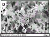
图3A、3B、3C和3D是根据本文公开和描述的实施方式的沉积到蜂窝体上的无定形相分解蒸发层前体的扫描电子显微镜(SEM)图像;3A, 3B, 3C and 3D are scanning electron microscope (SEM) images of an amorphous phase decomposed evaporated layer precursor deposited onto a honeycomb according to embodiments disclosed and described herein;
图4A、4B、4C和4D是根据本文公开和描述的实施方式,以不同的层前体流速沉积到蜂窝体上的无定形相分解蒸发层前体的透射电子显微镜(TEM)图像;4A, 4B, 4C and 4D are transmission electron microscope (TEM) images of amorphous phase decomposed evaporated layer precursors deposited onto a honeycomb at different layer precursor flow rates according to embodiments disclosed and described herein;
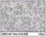
图5A、5B、5C和5D是根据本文公开和描述的实施方式的沉积到蜂窝体上的晶相涂层的扫描电子显微镜(SEM)图像;5A, 5B, 5C and 5D are scanning electron microscope (SEM) images of crystalline coatings deposited onto honeycombs according to embodiments disclosed and described herein;
图6是根据本文公开和描述的实施方式的蜂窝体的过滤效率图示;FIG6 is a graphical representation of the filtration efficiency of a honeycomb body according to embodiments disclosed and described herein;
图7A是根据本文公开和描述的实施方式的蜂窝体的背压与流速关系的图示;7A is a graphical representation of back pressure versus flow rate for a honeycomb according to embodiments disclosed and described herein;
图7B是根据本文公开和描述的实施方式的蜂窝体的背压与烟炱负载关系的图示;7B is a graphical representation of back pressure versus soot loading for a honeycomb according to embodiments disclosed and described herein;
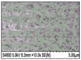
图8A和8B是根据本文公开和描述的实施方式的蜂窝体的SEM照片;8A and 8B are SEM images of honeycombs according to embodiments disclosed and described herein;
图9是根据本文公开和描述的实施方式的蜂窝体的过滤效率图示;FIG. 9 is a graphical representation of the filtration efficiency of a honeycomb body according to embodiments disclosed and described herein;
图10A是根据本文公开和描述的实施方式的蜂窝体的背压与流速关系的图示;FIG. 10A is a graphical representation of back pressure versus flow rate for a honeycomb according to embodiments disclosed and described herein;
图10B是根据本文公开和描述的实施方式的蜂窝体的背压与烟炱负载关系的图示;10B is a graphical representation of back pressure versus soot loading for a honeycomb according to embodiments disclosed and described herein;
图11A和11B是根据本文公开和描述的实施方式的蜂窝体的SEM照片;11A and 11B are SEM images of honeycombs according to embodiments disclosed and described herein;
图12是无定形相分解层前体(烧结之前的刚沉积状态)以及晶相陶瓷层(烧结之后)的XRD分析;FIG12 is an XRD analysis of an amorphous phase decomposition layer precursor (as deposited before sintering) and a crystalline ceramic layer (after sintering);
图13A和13B是根据本文公开和描述的实施方式的沉积到蜂窝体上的无定形相分解层前体的不同放大倍数的扫描电子显微镜图像;13A and 13B are scanning electron microscope images at different magnifications of an amorphous phase decomposed layer precursor deposited onto a honeycomb according to embodiments disclosed and described herein;
图13C和13D是根据本文公开和描述的实施方式的沉积到蜂窝体上的晶相陶瓷层的不同放大倍数的扫描电子显微镜图像;13C and 13D are scanning electron microscope images at different magnifications of a crystalline ceramic layer deposited onto a honeycomb according to embodiments disclosed and described herein;
图14显示处于刚沉积状态、在暴露于850℃持续6小时之后、暴露于850℃持续12小时之后以及暴露于1150℃烧结0.5小时之后的分解层前体的XRD扫描;FIG14 shows XRD scans of the decomposition layer precursor in the as-deposited state, after exposure to 850° C. for 6 hours, after exposure to 850° C. for 12 hours, and after exposure to 1150° C. for 0.5 hours;
图15是根据本文公开和描述的实施方式的蜂窝体的过滤效率图示;FIG. 15 is a graphical representation of the filtration efficiency of a honeycomb body according to embodiments disclosed and described herein;
图16A是根据本文公开和描述的实施方式的蜂窝体的背压与流速关系的图示;FIG. 16A is a graphical representation of back pressure versus flow rate for a honeycomb according to embodiments disclosed and described herein;
图16B是根据本文公开和描述的实施方式的蜂窝体的背压与烟炱负载关系的图示;16B is a graphical representation of back pressure versus soot loading for a honeycomb according to embodiments disclosed and described herein;
图17示意性显示根据本文公开和描述的实施方式的颗粒过滤器;FIG. 17 schematically illustrates a particle filter according to an embodiment disclosed and described herein;
图18是图17所示颗粒过滤器的横截面图;FIG18 is a cross-sectional view of the particulate filter shown in FIG17;
图19是根据实施方式的火焰热解工艺的流程图;FIG. 19 is a flow chart of a flame pyrolysis process according to an embodiment;
图20示意性显示根据一个或多个实施方式用于对颗粒过滤器进行测试的实验设备;FIG. 20 schematically shows an experimental apparatus for testing a particle filter according to one or more embodiments;
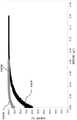
图21是根据本公开内容实施方式制造的两个实施例相比于比较例的过滤效率与时间(秒)的关系图;FIG. 21 is a graph of filtration efficiency versus time (seconds) for two examples made according to embodiments of the present disclosure compared to a comparative example;
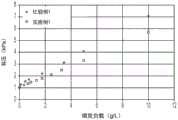
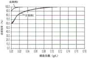
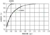
图22是根据本公开内容实施方式制造的两个实施例相比于比较例的过滤效率与烟炱负载(g/L)的关系图;FIG22 is a graph of filtration efficiency versus soot loading (g/L) for two examples made according to an embodiment of the present disclosure compared to a comparative example;
图23是根据本公开内容实施方式制造的两个实施例相比于比较例的压降与体积流量(m3/h)的关系图;FIG. 23 is a graph of pressure drop versus volume flow rate (m3 /h) for two examples made according to embodiments of the present disclosure compared to a comparative example;
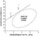
图24是实验室过滤效率/过滤面积(%/m2)与实验室压降(单位,kPa)的关系图;以及FIG24 is a graph showing the relationship between laboratory filtration efficiency/filtration area (%/m2 ) and laboratory pressure drop (unit: kPa); and
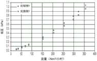
图25显示根据本公开内容实施方式制备的样品的参数NPV与参数NMFV的关系图。FIG. 25 shows a graph showing the relationship between the parameter NPV and the parameter NMFV for samples prepared according to an embodiment of the present disclosure.
具体实施方式DETAILED DESCRIPTION
下面将具体参考蜂窝体的实施方式,所述蜂窝体包括在其上具有高孔隙度的层的多孔蜂窝体,在附图中显示该实施方式。只要可能,在附图中使用相同的附图标记表示相同或相似的部分。在实施方式中,蜂窝体包括多孔陶瓷蜂窝体,其包括:第一端、第二端以及具有限定了多个内部通道的壁表面的多个壁。多孔无机层布置在蜂窝体的壁表面中的一个或多个上。无机层具有大于90%的孔隙度,以及无机层具有大于或等于0.5μm且小于或等于10μm的平均厚度。本文将具体参照附图来描述蜂窝体以及此类蜂窝体的制造方法的各种实施方式。在一些实施方式中,提供了颗粒过滤器,所述颗粒过滤器包括蜂窝体,所述蜂窝体包括堵塞住的多孔陶瓷蜂窝结构,所述堵塞住的多孔陶瓷蜂窝结构包括多个交叉多孔壁,所述多孔壁包括多孔壁表面,所述多孔壁表面限定了从结构的入口端延伸到出口端的多个通道,所述多个通道包括在出口端处或者靠近出口端处密封住且具有表面积的入口通道以及在入口端处或者靠近入口端处密封住且具有表面积的出口通道,所述入口通道和出口通道限定了过滤区域,其中,多孔壁表面中限定了入口通道的一个或多个包括底壁部分和布置在底壁部分上的过滤材料沉积物,其中,过滤材料沉积物布置在底壁部分上,以及其中,在室温下,在暴露于850Nm3/h空气的高流量条件持续1分钟之后,颗粒过滤器展现出小于5%的过滤效率变化,以及其中,通过在暴露于高流量条件之前和之后,测量引入到颗粒过滤器中的烟炱颗粒的数量与离开颗粒过滤器的烟炱颗粒的数量之差来确定过滤效率的变化,其中,烟炱颗粒的中值粒度是300nm,以51Nm3/h的流速、室温和1.7m/s的速度流动通过颗粒过滤器的空气流中的烟炱颗粒浓度是500,000个颗粒/cm3,这是通过颗粒计数器测得的(例如,使用灯塔手持式(Lighthouse Handheld)3016 0.1CFM颗粒计数器,购自灯塔全球解决方案公司(Lighthouse Worldwide Solutions),颗粒过滤器上游30秒,以及颗粒过滤器下游30秒)。在一些实施方式中,在室温下,在暴露于850Nm3/h空气的高流量条件持续1分钟之后,颗粒过滤器展现出的过滤效率变化小于20%、15%、10%、9%、8%、7%、6%、5%、4%、3%、2%或者甚至小于1%。Specific reference will be made below to an embodiment of a honeycomb body, which includes a porous honeycomb body having a layer of high porosity thereon, which embodiment is shown in the accompanying drawings. Whenever possible, the same reference numerals are used in the drawings to represent the same or similar parts. In an embodiment, the honeycomb body includes a porous ceramic honeycomb body, which includes: a first end, a second end, and a plurality of walls having wall surfaces defining a plurality of internal channels. The porous inorganic layer is arranged on one or more of the wall surfaces of the honeycomb body. The inorganic layer has a porosity greater than 90%, and the inorganic layer has an average thickness greater than or equal to 0.5 μm and less than or equal to 10 μm. Various embodiments of honeycombs and methods of making such honeycombs will be described herein with specific reference to the accompanying drawings. In some embodiments, a particle filter is provided, the particle filter comprising a honeycomb body, the honeycomb body comprising a plugged porous ceramic honeycomb structure, the plugged porous ceramic honeycomb structure comprising a plurality of intersecting porous walls, the porous walls comprising a porous wall surface, the porous wall surface defining a plurality of channels extending from an inlet end to an outlet end of the structure, the plurality of channels comprising an inlet channel sealed at or near the outlet end and having a surface area and an outlet channel sealed at or near the inlet end and having a surface area, the inlet channel and the outlet channel defining a filtration region, wherein one or more of the porous wall surfaces defining the inlet channel comprises a bottom wall portion and a filter material deposit disposed on the bottom wall portion, wherein the filter material deposit is disposed on the bottom wall portion, and wherein at room temperature, upon exposure to 850 Nm3 The particle filter exhibits a filtration efficiency change of less than 5% after a high flow condition of 100 Nm 3 /h of air is maintained for 1 minute, and wherein the change in filtration efficiency is determined by measuring the difference between the number of soot particles introduced into the particle filter and the number of soot particles exiting the particle filter before and after exposure to the high flow condition, wherein the median particle size of the soot particles is 300 nm, and the concentration of soot particles in the air flow flowing through the particle filter at a flow rate of 51 Nm3 /h, room temperature and a velocity of 1.7 m/s is 500,000 particles/cm3 , which is measured by a particle counter (e.g., using a Lighthouse Handheld 3016 0.1 CFM particle counter, available from Lighthouse Worldwide Solutions, 30 seconds upstream of the particle filter, and 30 seconds downstream of the particle filter). In some embodiments, the particle filter exhibits a filtration efficiency change of less than 20%, 15%, 10%, 9%, 8%, 7%, 6%, 5%, 4%, 3%, 2% or even less than 1% after exposure to a high flow condition of 850
在一些实施方式中,过滤材料沉积物优选是机械稳定的,例如对于例如由于高气体流量通过颗粒过滤器的堵塞蜂窝结构所导致的和/或例如由于机械振动所导致的移动或重新排布具有抗性。在一个或多个实施方式中,当暴露于水时,过滤材料沉积物是稳定的,从而沉积物维持它们在孔道壁上的方位或位置。换言之,根据一些实施方式,过滤材料沉积物与多孔陶瓷底壁粘结。在一些实施方式中,沉积物是化学粘结的,而不仅仅是通过物理粘结方式进行粘结。例如,在一些实施方式中,火焰热解过滤材料沉积物融合到或者烧结到多孔陶瓷底壁。此外,在一些实施方式中,火焰热解过滤材料沉积物相互融合或烧结以形成多孔无机材料层。In some embodiments, the filter material deposits are preferably mechanically stable, such as being resistant to movement or rearrangement, such as due to a blockage of the honeycomb structure of the particle filter due to high gas flow rates and/or due to mechanical vibrations. In one or more embodiments, the filter material deposits are stable when exposed to water, such that the deposits maintain their orientation or position on the pore walls. In other words, according to some embodiments, the filter material deposits are bonded to the porous ceramic bottom wall. In some embodiments, the deposits are chemically bonded, rather than simply bonded by physical bonding. For example, in some embodiments, flame pyrolysis filter material deposits are fused to or sintered to the porous ceramic bottom wall. Furthermore, in some embodiments, flame pyrolysis filter material deposits are fused or sintered to each other to form a porous inorganic material layer.
如本明书和所附权利要求书中所用,除非上下文中有明显的表示,否则单数形式的“一个”,“一种”和“该”包括具有多个指示物的实施方式。如本明书和所附权利要求书中所用,除非上下文中有明显的表示,否则术语“或”通常采用其包括“和/或”的意义。As used in this specification and the appended claims, the singular forms "a," "an," and "the" include embodiments having plural referents unless the context clearly dictates otherwise. As used in this specification and the appended claims, the term "or" is generally employed in its sense including "and/or" unless the context clearly dictates otherwise.
如本文所用,“具有”、“有”、“包括”、“包括了”、“包含”或者“包含了”等,用于它们的开放表现形式,并且通常表示“包括,但不限于”。As used herein, "having," "including," "comprising," "includes," or "including," are used in their open forms and generally mean "including, but not limited to."
如本文所用,蜂窝体是交叉壁的具有形状的陶瓷蜂窝结构,所述交叉壁形成孔道以限定通道。陶瓷蜂窝结构可以是经过成形的、挤出的或者模制的,并且可以是任意形状或尺寸。例如,可以从堇青石或者其他合适的陶瓷材料形成陶瓷蜂窝结构。As used herein, a honeycomb is a shaped ceramic honeycomb structure of intersecting walls that form channels to define passages. The ceramic honeycomb structure can be formed, extruded or molded and can be of any shape or size. For example, a ceramic honeycomb structure can be formed from cordierite or other suitable ceramic materials.
如本文所用,蜂窝体也可以定义为具有形状的陶瓷蜂窝结构,在蜂窝结构的壁表面施涂了至少一层,其构造成从气流过滤颗粒物质。在蜂窝结构的同一位置上,可能施涂了不止一层。层可以是无机的或者有机的,或者可以是这两种情况。例如,在一个或多个实施方式中,可以从堇青石或者其他陶瓷材料形成蜂窝体,并且可以具有施涂到堇青石蜂窝结构的表面的高孔隙率层。层可以是“过滤材料”,其用于提供增强的过滤效率,是局部穿过壁和位于壁处以及整体穿过蜂窝体这两种情况。不将过滤材料认为是催化活性的,原因在于,其不与尾气流的气态混合物的组分发生反应。As used herein, a honeycomb body may also be defined as a shaped ceramic honeycomb structure having at least one layer applied to the wall surface of the honeycomb structure, which is configured to filter particulate matter from an airflow. More than one layer may be applied to the same location of the honeycomb structure. The layer may be inorganic or organic, or both. For example, in one or more embodiments, a honeycomb body may be formed from cordierite or other ceramic materials, and may have a high porosity layer applied to the surface of the cordierite honeycomb structure. The layer may be a "filter material" that is used to provide enhanced filtration efficiency, both locally through the wall and at the wall and as a whole through the honeycomb body. The filter material is not considered to be catalytically active because it does not react with the components of the gaseous mixture of the exhaust gas stream.
如本文所用,“生坯”或者“生坯陶瓷”可互换使用,并且除非另有说明,否则指的是未烧结的材料。As used herein, "green" or "green ceramic" are used interchangeably and refer to unsintered material unless otherwise specified.
一个或多个实施方式的蜂窝体可以包括蜂窝结构以及布置在蜂窝结构的一个或多个壁上的层。在一些实施方式中,层施涂到存在于蜂窝结构中的壁的表面,在那里,壁具有限定了多个内部通道的表面。当存在时,内部通道可以具有各种横截面形状,例如圆形、椭圆形、三角形、方形、五边形、六边形或棋盘状或这些的任意组合,并且可以以任何合适的几何构造来排布。当存在时,内部通道可以是离散的或交叉的,并且可以延伸穿过蜂窝体从其第一端部到达与第一端相对的第二端。The honeycomb of one or more embodiments may include a honeycomb structure and a layer disposed on one or more walls of the honeycomb structure. In some embodiments, the layer is applied to the surface of the wall present in the honeycomb structure, where the wall has a surface defining a plurality of internal channels. When present, the internal channels may have a variety of cross-sectional shapes, such as circular, elliptical, triangular, square, pentagonal, hexagonal, or chessboard-shaped or any combination of these, and may be arranged in any suitable geometric configuration. When present, the internal channels may be discrete or intersecting and may extend through the honeycomb from its first end to a second end opposite the first end.
现参见图1,显示了根据本文所示和所述一个或多个实施方式的蜂窝体100。在实施方式中,蜂窝体100包括限定了多个内部通道110的多个壁115。所述多个内部通道110和交叉通道壁115在蜂窝体的第一端105与第二端135之间延伸。1, a
在一个或多个实施方式中,可以由堇青石、钛酸铝、顽辉石、多铝红柱石、镁橄榄石、刚玉(SiC)、尖晶石、蓝宝石和方镁石形成蜂窝体。通常来说,堇青石是具有根据化学式(Mg,Fe)2Al3(Si5AlO18)的组成的固溶体。在一些实施方式中,通过改变陶瓷原材料的粒度,可以控制陶瓷材料的孔径,可以控制陶瓷材料的孔隙率,以及可以控制陶瓷材料的粒度分布。此外,可以在用于形成蜂窝体的陶瓷批料中包括成孔剂。In one or more embodiments, a honeycomb may be formed from cordierite, aluminum titanate, enstatite, mullite, forsterite, corundum (SiC), spinel, sapphire, andpericlase . Generally, cordierite is a solid solution having a composition according to the chemical formula (Mg,Fe)2Al3 (Si5AlO18 ). In some embodiments, by changing the particle size of the ceramic raw materials, the pore size of the ceramic material may be controlled, the porosity of the ceramic material may be controlled, andthe particle size distribution of the ceramic material may be controlled. In addition, a pore former may be included in the ceramic batch used to form the honeycomb.
在一些实施方式中,蜂窝体的壁的平均厚度可以是大于或等于25μm至小于或等于250μm,例如:大于或等于45μm至小于或等于230μm、大于或等于65μm至小于或等于210μm、大于或等于65μm至小于或等于190μm或者大于或等于85μm至小于或等于170μm。蜂窝体的壁可以被描述为具有:包含本体部分(本文也称作本体的)底壁部分,以及表面部分(本文也称作表面)。壁的表面部分从蜂窝体的壁的表面朝向蜂窝体的本体部分延伸进入壁中。表面部分可以从0(零)延伸进入蜂窝体的壁的底壁部分中达到约10μm的深度。在一些实施方式中,表面部分可以延伸进入到壁的底壁部分中约5μm、约7μm或者约9μm(即,深度为0(零))。蜂窝体的本体部分构成壁减去表面部分的厚度。因此,可以通过如下等式确定蜂窝体的本体部分:In some embodiments, the average thickness of the wall of the honeycomb body can be greater than or equal to 25 μm and less than or equal to 250 μm, for example: greater than or equal to 45 μm and less than or equal to 230 μm, greater than or equal to 65 μm and less than or equal to 210 μm, greater than or equal to 65 μm and less than or equal to 190 μm, or greater than or equal to 85 μm and less than or equal to 170 μm. The wall of the honeycomb body can be described as having: a bottom wall portion including a body portion (also referred to herein as the body), and a surface portion (also referred to herein as the surface). The surface portion of the wall extends into the wall from the surface of the wall of the honeycomb body toward the body portion of the honeycomb body. The surface portion can extend from 0 (zero) into the bottom wall portion of the wall of the honeycomb body to a depth of about 10 μm. In some embodiments, the surface portion can extend into the bottom wall portion of the wall by about 5 μm, about 7 μm, or about 9 μm (i.e., a depth of 0 (zero)). The body portion of the honeycomb body constitutes the thickness of the wall minus the surface portion. Therefore, the body portion of the honeycomb body can be determined by the following equation:
t总-2t表面ttotal -2tsurface
式中,t总是壁的总厚度,以及t表面是壁表面的厚度。Where ttois the total thickness of the wall, andtsurface is the thickness of the wall surface.
在一个或多个实施方式中,蜂窝体的本体的本体平均孔径(bulk mean poresize)是大于或等于7μm至小于或等于25μm,例如:大于或等于12μm至小于或等于22μm或者大于或等于12μm至小于或等于18μm。例如,在一些实施方式中,蜂窝体的本体的本体平均孔径可以是约10μm、约11μm、约12μm、约13μm、约14μm、约15μm、约16μm、约17μm、约18μm、约19μm或者约20μm。通常来说,任何给定材料的孔径存在统计学分布。因此,术语“中指孔径”或者“D50”指的是基于所有孔的统计学分布,50%的孔位于其和低于其,且余下50%的孔位于其的情况。可以通过以下至少一种方式在陶瓷体中制造孔:(1)无机批料材料粒度和尺寸分布;(2)炉/热处理烧制时间和温度方案;(3)炉气氛(例如,低或高的氧含量和/或水含量);以及(4)成孔剂,例如:聚合物和聚合物颗粒、淀粉、木质面粉、空心无机颗粒和/或石墨/碳颗粒。In one or more embodiments, the bulk mean pore size of the body of the honeycomb is greater than or equal to 7 μm to less than or equal to 25 μm, for example: greater than or equal to 12 μm to less than or equal to 22 μm or greater than or equal to 12 μm to less than or equal to 18 μm. For example, in some embodiments, the bulk mean pore size of the body of the honeycomb can be about 10 μm, about 11 μm, about 12 μm, about 13 μm, about 14 μm, about 15 μm, about 16 μm, about 17 μm, about 18 μm, about 19 μm, or about 20 μm. Generally speaking, there is a statistical distribution of pore sizes for any given material. Therefore, the term "median pore size" or "D50" refers to the situation where 50% of the pores are located at and below it, and the remaining 50% of the pores are located at it, based on the statistical distribution of all pores. Pores can be created in a ceramic body by at least one of the following: (1) inorganic batch material particle size and size distribution; (2) furnace/heat treatment firing time and temperature schedule; (3) furnace atmosphere (e.g., low or high oxygen content and/or water content); and (4) pore formers, such as: polymers and polymer particles, starch, wood flour, hollow inorganic particles, and/or graphite/carbon particles.
在一些实施方式中,在不考虑涂层的情况下,蜂窝体的本体的本体孔隙度可以是大于或等于50%至小于或等于70%,这是通过压汞法测量的。测量表面孔隙度的方法包括扫描电子显微镜(SEM),这个方法对于测量相互独立的表面孔隙度和本体孔隙度是特别有用的。在一个或多个实施方式中,蜂窝体的本体孔隙度可以是例如小于70%、小于65%、60%、小于58%、小于56%、小于54%或者小于52%。In some embodiments, the bulk porosity of the honeycomb body, without taking into account the coating, can be greater than or equal to 50% to less than or equal to 70%, as measured by mercury intrusion. Methods for measuring surface porosity include scanning electron microscopy (SEM), which is particularly useful for measuring surface porosity and bulk porosity independently of each other. In one or more embodiments, the bulk porosity of the honeycomb body can be, for example, less than 70%, less than 65%, 60%, less than 58%, less than 56%, less than 54%, or less than 52%.
在一个或多个实施方式中,蜂窝体的表面部分的表面中值孔径是大于或等于7μm至小于或等于20μm,例如:大于或等于8μm至小于或等于15μm或者大于或等于10μm至小于或等于14μm。例如,在一些实施方式中,蜂窝体的表面的表面中值孔径可以是约8μm、约9μm、约10μm、约11μm、约12μm、约13μm、约14μm或者约15μm。In one or more embodiments, the surface median pore size of the surface portion of the honeycomb body is greater than or equal to 7 μm to less than or equal to 20 μm, for example, greater than or equal to 8 μm to less than or equal to 15 μm or greater than or equal to 10 μm to less than or equal to 14 μm. For example, in some embodiments, the surface median pore size of the surface of the honeycomb body can be about 8 μm, about 9 μm, about 10 μm, about 11 μm, about 12 μm, about 13 μm, about 14 μm, or about 15 μm.
在一些实施方式中,在施涂层之前,蜂窝体的表面的表面孔隙度可以是大于或等于35%至小于或等于50%,这是通过SEM测量的。在一个或多个实施方式中,蜂窝体的表面孔隙度可以小于65%,例如:小于60%、小于55%、小于50%、小于48%、小于46%、小于44%、小于42%、小于40%、小于48%或者小于36%。In some embodiments, the surface porosity of the surface of the honeycomb body prior to application of the coating may be greater than or equal to 35% to less than or equal to 50%, as measured by SEM. In one or more embodiments, the surface porosity of the honeycomb body may be less than 65%, for example, less than 60%, less than 55%, less than 50%, less than 48%, less than 46%, less than 44%, less than 42%, less than 40%, less than 48%, or less than 36%.
现参见图17和18,示意性显示了颗粒过滤器300的形式的蜂窝体。颗粒过滤器300可以用作壁流式过滤器对来自尾气流350(例如,从汽油发动机排放的尾气流,在这种情况下,颗粒过滤器300是汽油颗粒过滤器)的颗粒物质进行过滤。颗粒过滤器300通常包括蜂窝体,所述蜂窝体具有在入口端302与出口端404之间延伸的多个通道301或孔道,限定了整体长度La。通过从入口端302延伸到出口端304的多个交叉通道壁306形成且至少部分限定了颗粒过滤器300的通道301。颗粒过滤器300还可以包括绕着所述多个通道301的表皮层305。所述外皮可以在形成通道壁306的过程中挤出形成这种表皮层305,或者可以在之后的加工中作为后施加的表皮层形成,例如通过将表皮黏结剂施涂于通道的外周边部分。Referring now to FIGS. 17 and 18 , a honeycomb in the form of a
如图18所示是图17的颗粒过滤器300的轴向横截面。在一些实施方式中,将某些通道指定为入口通道308,以及将某些其它通道指定为出口通道310。在颗粒过滤器300的一些实施方式中,至少第一组通道可以被堵塞物312堵塞住。通常来说,堵塞物312布置在靠近通道301的端部(即,入口端或出口端)。堵塞物通常以预定式样排布,例如如图17所示的棋盘式样,每个其他通道在端部被堵塞住。入口通道308可以在出口端304处或附近堵塞住,以及出口通道310可以在不对应于入口通道的通道上的入口端302处或附近堵塞住,如图3所示。因此,每个孔道可以仅在颗粒过滤器的一端处或附近被堵塞住。As shown in FIG. 18, an axial cross-section of the
虽然图17大致显示了棋盘堵塞式样,但是应理解的是,在多孔陶瓷蜂窝制品中可以选择替代的堵塞式样。在本文所述的实施方式中,颗粒过滤器300可以形成为具有最高至约600个通道/平方英寸(cpsi)的通道密度。例如,在一些实施方式中,颗粒过滤器100可以具有约100cpsi至约600cpsi的通道密度。在一些其他实施方式中,颗粒过滤器100可以具有约100cpsi至约400cpsi或者甚至约200cpsi至约300cpsi的通道密度。Although FIG. 17 generally shows a checkerboard plugging pattern, it should be understood that alternative plugging patterns may be selected in porous ceramic honeycomb articles. In the embodiments described herein, the
在本文所述的实施方式中,颗粒过滤器300的通道壁306可以具有大于约4密耳(101.6微米)的厚度。例如,在一些实施方式中,通道壁306的厚度可以是约4密耳至最高至约30密耳(762微米)。在一些其他实施方式中,通道壁306的厚度可以是约7密耳(177.8微米)至约20密耳(508微米)。In the embodiments described herein, the
在各种实施方式中,蜂窝体构造成从气流过滤颗粒物质。因此,对蜂窝体的本体和表面这两者的中值孔径、孔隙度、几何形貌和其他设计方面进行选择,以考虑蜂窝体的这些过滤要求。例如,如图2的实施方式所示,蜂窝体200的壁210具有布置在其上的层220,优选通过热处理烧结或者任意其他方式粘结。层220可以包括颗粒225,所述颗粒225沉积在蜂窝体200的壁210上并且帮助防止颗粒物质随着气流230离开蜂窝体(例如,烟炱和灰),以及帮助防止颗粒物质阻塞住蜂窝体200的壁210的底壁部分。以这种方式,根据实施方式,层220可以作为主要过滤组分,而蜂窝体的底壁部分可以构造成以任意其他方式使得压降最小化,例如相比于没有此类层的常规蜂窝体而言。如本文所用,压降是采用差式压力传感器进行测量,测量的是过滤器的轴向长度上的压力下降。由于层220的孔径小于底壁部分,所以层会过滤掉大部分的较小尺寸的颗粒物质,但是预期蜂窝体过滤器的壁的底壁部分对于过滤一些较大尺寸的颗粒物质是有效的。如本文更详细描述,可以通过合适的方法形成蜂窝体,例如火焰沉积法,其实现了在蜂窝体的壁的至少一些表面上形成高度多孔的薄层。In various embodiments, the honeycomb is configured to filter particulate matter from an airflow. Therefore, the median pore size, porosity, geometry and other design aspects of both the body and the surface of the honeycomb are selected to take into account these filtering requirements of the honeycomb. For example, as shown in the embodiment of FIG. 2, the
在一个或多个实施方式中,通过SEM测得的布置在蜂窝体的壁上的层的孔隙度大于或等于80%,例如大于90%。在其他实施方式中,布置在蜂窝体的壁上的层的孔隙度大于或等于92%,例如大于或等于93%或者大于或等于94%。在其他实施方式中,布置在蜂窝体的壁上的层的孔隙度大于或等于95%,例如大于或等于96%或者大于或等于97%。在各种实施方式中,布置在蜂窝体的壁上的层的孔隙度小于或等于99%,例如小于或等于97%、小于或等于95%、小于或等于94%或者小于或等于93%。相比于在其上不包含层的同样的蜂窝体的压降,蜂窝体的壁上的层的高孔隙度实现在不明显影响蜂窝体的压降的情况下将层施涂到蜂窝体。SEM和X射线断层摄影用于测量相互独立的表面和本体孔隙度。通过密度计算获得孔隙度,其包括:测量无机层的重量及其厚度来得到层密度,以及根据等式层孔隙度=1–层密度/无机材料密度来计算层的孔隙度。例如,对于包含多铝红柱石的层,“无机材料密度”是多铝红柱石的密度。In one or more embodiments, the porosity of the layer disposed on the wall of the honeycomb body is greater than or equal to 80%, such as greater than 90%, as measured by SEM. In other embodiments, the porosity of the layer disposed on the wall of the honeycomb body is greater than or equal to 92%, such as greater than or equal to 93% or greater than or equal to 94%. In other embodiments, the porosity of the layer disposed on the wall of the honeycomb body is greater than or equal to 95%, such as greater than or equal to 96% or greater than or equal to 97%. In various embodiments, the porosity of the layer disposed on the wall of the honeycomb body is less than or equal to 99%, such as less than or equal to 97%, less than or equal to 95%, less than or equal to 94%, or less than or equal to 93%. The high porosity of the layer on the wall of the honeycomb body enables the layer to be applied to the honeycomb body without significantly affecting the pressure drop of the honeycomb body compared to the pressure drop of the same honeycomb body without the layer thereon. SEM and X-ray tomography are used to measure surface and bulk porosity independently of each other. The porosity is obtained by density calculation, which includes: measuring the weight of the inorganic layer and its thickness to obtain the layer density, and calculating the porosity of the layer according to the equation layer porosity = 1 - layer density / inorganic material density. For example, for a layer containing mullite, the "inorganic material density" is the density of mullite.
如上文所述,蜂窝体的壁上的层相对于蜂窝体的壁的底壁部分的厚度是非常薄的,并且层还具有非常高的孔隙度和渗透性。如下文更详细讨论,可以通过能够以非常薄层的方式将层施涂到蜂窝体的壁的表面的方法在蜂窝体上形成层。在实施方式中,蜂窝体的壁的底壁部分上的层的平均厚度是大于或等于0.5μm至小于或等于30μm,例如大于或等于0.5μm至小于或等于20μm,大于或等于0.5μm至小于或等于10μm,例如大于或等于0.5μm至小于或等于5μm,大于或等于1μm至小于或等于4.5μm,大于或等于1.5μm至小于或等于4μm,或者大于或等于2μm至小于或等于3.5μm。As described above, the layer on the wall of the honeycomb is very thin relative to the thickness of the bottom wall portion of the wall of the honeycomb, and the layer also has a very high porosity and permeability. As discussed in more detail below, the layer can be formed on the honeycomb by a method that can apply the layer to the surface of the wall of the honeycomb in a very thin layer. In an embodiment, the average thickness of the layer on the bottom wall portion of the wall of the honeycomb is greater than or equal to 0.5 μm to less than or equal to 30 μm, such as greater than or equal to 0.5 μm to less than or equal to 20 μm, greater than or equal to 0.5 μm to less than or equal to 10 μm, such as greater than or equal to 0.5 μm to less than or equal to 5 μm, greater than or equal to 1 μm to less than or equal to 4.5 μm, greater than or equal to 1.5 μm to less than or equal to 4 μm, or greater than or equal to 2 μm to less than or equal to 3.5 μm.
如上文所讨论的那样,可以通过能够使得无机层具有小的中值孔径的方法将层施涂到蜂窝体的壁。这种小的中值孔径实现了层过滤掉高百分比的颗粒,并且防止颗粒渗透蜂窝体并沉积到蜂窝体的孔中,如上文关于图2所述。根据实施方式的层的小的中值孔径增加了蜂窝体的过滤效率。在一个或多个实施方式中,蜂窝体的壁上的层的中值孔径是大于或等于0.1μm至小于或等于5μm,例如:大于或等于0.5μm至小于或等于4μm或者大于或等于0.6μm至小于或等于3μm。例如,在一些实施方式中,蜂窝体的壁上的层的中值孔径可以是约0.5μm、约0.6μm、约0.7μm、约0.8μm、约0.9μm、约1μm、约2μm、约3μm或者约4μm。As discussed above, the layer can be applied to the wall of the honeycomb by a method that enables the inorganic layer to have a small median pore size. This small median pore size enables the layer to filter out a high percentage of particles and prevents particles from penetrating the honeycomb and depositing into the pores of the honeycomb, as described above with respect to FIG. 2. The small median pore size of the layer according to the embodiment increases the filtration efficiency of the honeycomb. In one or more embodiments, the median pore size of the layer on the wall of the honeycomb is greater than or equal to 0.1 μm to less than or equal to 5 μm, for example: greater than or equal to 0.5 μm to less than or equal to 4 μm or greater than or equal to 0.6 μm to less than or equal to 3 μm. For example, in some embodiments, the median pore size of the layer on the wall of the honeycomb can be about 0.5 μm, about 0.6 μm, about 0.7 μm, about 0.8 μm, about 0.9 μm, about 1 μm, about 2 μm, about 3 μm, or about 4 μm.
虽然在一些实施方式中,蜂窝体的壁上的层可以覆盖基本上100%的限定了蜂窝体的内部通道的壁表面,但是在其他实施方式中,蜂窝体的壁上的层覆盖了少于基本上100%的限定了蜂窝体的内部通道的壁表面。例如,在一个或多个实施方式中,蜂窝体的壁上的层覆盖了至少70%的限定了蜂窝体的内部通道的壁表面,覆盖了至少75%的限定了蜂窝体的内部通道的壁表面,覆盖了至少80%的限定了蜂窝体的内部通道的壁表面,覆盖了至少85%的限定了蜂窝体的内部通道的壁表面,覆盖了至少90%的限定了蜂窝体的内部通道的壁表面,或者覆盖了至少85%的限定了蜂窝体的内部通道的壁表面。While in some embodiments, the layer on the wall of the honeycomb body can cover substantially 100% of the surface of the walls defining the interior channels of the honeycomb body, in other embodiments, the layer on the wall of the honeycomb body covers less than substantially 100% of the surface of the walls defining the interior channels of the honeycomb body. For example, in one or more embodiments, the layer on the wall of the honeycomb body covers at least 70% of the surface of the walls defining the interior channels of the honeycomb body, covers at least 75% of the surface of the walls defining the interior channels of the honeycomb body, covers at least 80% of the surface of the walls defining the interior channels of the honeycomb body, covers at least 85% of the surface of the walls defining the interior channels of the honeycomb body, covers at least 90% of the surface of the walls defining the interior channels of the honeycomb body, or covers at least 85% of the surface of the walls defining the interior channels of the honeycomb body.
如上文参见图1所述,蜂窝体可以具有第一端和第二端。第一端和第二端间隔轴向长度。在一些实施方式中,蜂窝体的壁上的层可以延伸蜂窝体的整个轴向长度(即,沿着100%的轴向长度延伸)。但是,在其他实施方式中,蜂窝体的壁上的层沿着至少60%的轴向长度延伸,例如:沿着至少65%的轴向长度延伸,沿着至少70%的轴向长度延伸,沿着至少75%的轴向长度延伸,沿着至少80%的轴向长度延伸,沿着至少85%的轴向长度延伸,沿着至少90%的轴向长度延伸,或者沿着至少95%的轴向长度延伸。As described above with reference to FIG. 1 , the honeycomb body can have a first end and a second end. The first end and the second end are separated by an axial length. In some embodiments, the layer on the wall of the honeycomb body can extend the entire axial length of the honeycomb body (i.e., extend along 100% of the axial length). However, in other embodiments, the layer on the wall of the honeycomb body extends along at least 60% of the axial length, for example: extends along at least 65% of the axial length, extends along at least 70% of the axial length, extends along at least 75% of the axial length, extends along at least 80% of the axial length, extends along at least 85% of the axial length, extends along at least 90% of the axial length, or extends along at least 95% of the axial length.
在实施方式中,蜂窝体的壁上的层从蜂窝体的第一端延伸到蜂窝体的第二端。在一些实施方式中,蜂窝体的壁上的层延伸从蜂窝体的第一表面到蜂窝体的第二表面的整个距离(即,沿着从蜂窝体的第一表面到蜂窝体的第二表面的100%的距离延伸)。但是,在一个或多个实施方式中,蜂窝体的壁上的层沿着蜂窝体的第一表面与蜂窝体的第二表面之间的距离的60%延伸,例如沿着蜂窝体的第一表面与蜂窝体的第二表面之间的距离的65%延伸,沿着蜂窝体的第一表面与蜂窝体的第二表面之间的距离的70%延伸,沿着蜂窝体的第一表面与蜂窝体的第二表面之间的距离的75%延伸,沿着蜂窝体的第一表面与蜂窝体的第二表面之间的距离的80%延伸,沿着蜂窝体的第一表面与蜂窝体的第二表面之间的距离的85%延伸,沿着蜂窝体的第一表面与蜂窝体的第二表面之间的距离的90%延伸,或者沿着蜂窝体的第一表面与蜂窝体的第二表面之间的距离的95%延伸。In an embodiment, the layer on the wall of the honeycomb body extends from the first end of the honeycomb body to the second end of the honeycomb body. In some embodiments, the layer on the wall of the honeycomb body extends the entire distance from the first surface of the honeycomb body to the second surface of the honeycomb body (i.e., extends along 100% of the distance from the first surface of the honeycomb body to the second surface of the honeycomb body). However, in one or more embodiments, the layer on the wall of the honeycomb body extends along 60% of the distance between the first surface of the honeycomb body and the second surface of the honeycomb body, for example, along 65% of the distance between the first surface of the honeycomb body and the second surface of the honeycomb body, along 70% of the distance between the first surface of the honeycomb body and the second surface of the honeycomb body, along 75% of the distance between the first surface of the honeycomb body and the second surface of the honeycomb body, along 80% of the distance between the first surface of the honeycomb body and the second surface of the honeycomb body, along 85% of the distance between the first surface of the honeycomb body and the second surface of the honeycomb body, along 90% of the distance between the first surface of the honeycomb body and the second surface of the honeycomb body, or along 95% of the distance between the first surface of the honeycomb body and the second surface of the honeycomb body.
在一个或多个实施方式中,蜂窝体的壁上的层作为连续涂层布置在壁表面上。如本文所用,“连续涂层”是这样一种区域,其中,该区域的任何部分都基本上没有裸露或者没有层材料。在一个或多个实施方式中,至少50%的层作为连续层布置在蜂窝体的壁表面上,例如:至少60%的层作为连续层布置在蜂窝体的壁表面上,至少70%的层作为连续层布置在蜂窝体的壁表面上,至少80%的层作为连续层布置在蜂窝体的壁表面上,至少90%的层作为连续层布置在蜂窝体的壁表面上,至少92%的层作为连续层布置在蜂窝体的壁表面上,至少94%的层作为连续层布置在蜂窝体的壁表面上,至少96%的层作为连续层布置在蜂窝体的壁表面上,或者至少98%的层作为连续层布置在蜂窝体的壁表面上。在其他实施方式中,100%的层作为连续层布置在蜂窝体的壁表面上。In one or more embodiments, the layer on the wall of the honeycomb is arranged as a continuous coating on the wall surface. As used herein, a "continuous coating" is a region in which any portion of the region is substantially free of exposed or layer material. In one or more embodiments, at least 50% of the layer is arranged as a continuous layer on the wall surface of the honeycomb, for example: at least 60% of the layer is arranged as a continuous layer on the wall surface of the honeycomb, at least 70% of the layer is arranged as a continuous layer on the wall surface of the honeycomb, at least 80% of the layer is arranged as a continuous layer on the wall surface of the honeycomb, at least 90% of the layer is arranged as a continuous layer on the wall surface of the honeycomb, at least 92% of the layer is arranged as a continuous layer on the wall surface of the honeycomb, at least 94% of the layer is arranged as a continuous layer on the wall surface of the honeycomb, at least 96% of the layer is arranged as a continuous layer on the wall surface of the honeycomb, or at least 98% of the layer is arranged as a continuous layer on the wall surface of the honeycomb. In other embodiments, 100% of the layer is arranged as a continuous layer on the wall surface of the honeycomb.
如上文所述,并且不受限于任何特定理论,相信通过实施方式的蜂窝体实现低压降的原因在于,蜂窝体上的层是蜂窝体的主要过滤组分,这实现了更灵活的蜂窝体设计。根据实施方式选择具有低压降的蜂窝体结合蜂窝体上的低厚度和高孔隙度的层,这实现了实施方式的蜂窝体具有相比于常规蜂窝体更低的压降。在实施方式中,蜂窝体上的层是0.1至30g/L。在实施方式中,存在的层可以是:0.2至20g/L、0.3至25g/L、0.4至20g/L、1至10g/L。在一些实施方式中,相比于没有薄的高孔隙度无机层的蜂窝体,所述蜂窝体上的压降(即,没有烟炱或灰的清洁压降)小于或等于10%,例如小于或等于9%或者小于或等于8%。在其他实施方式中,蜂窝体上的压降小于或等于7%,例如小于或等于6%。在其他实施方式中,蜂窝体上的压降小于或等于5%,例如小于或等于4%或者小于或等于3%。As described above, and without being limited to any particular theory, it is believed that the reason for the low pressure drop achieved by the honeycomb of the embodiment is that the layer on the honeycomb is the main filtering component of the honeycomb, which enables a more flexible honeycomb design. The honeycomb with low pressure drop is selected according to the embodiment in combination with the low thickness and high porosity layer on the honeycomb, which enables the honeycomb of the embodiment to have a lower pressure drop than a conventional honeycomb. In an embodiment, the layer on the honeycomb is 0.1 to 30 g/L. In an embodiment, the layer present can be: 0.2 to 20 g/L, 0.3 to 25 g/L, 0.4 to 20 g/L, 1 to 10 g/L. In some embodiments, the pressure drop on the honeycomb (i.e., the clean pressure drop without soot or ash) is less than or equal to 10%, such as less than or equal to 9% or less than or equal to 8%, compared to a honeycomb without a thin high porosity inorganic layer. In other embodiments, the pressure drop on the honeycomb is less than or equal to 7%, such as less than or equal to 6%. In other embodiments, the pressure drop across the honeycomb body is less than or equal to 5%, such as less than or equal to 4% or less than or equal to 3%.
如上文所述,并且不受限于任何特定理论,蜂窝体的壁上的层中的小的孔尺寸实现了蜂窝体具有良好的过滤效率,即使是在蜂窝体中发生灰或烟炱积累之前也是如此。本文采用Tandon等人提出的方案(65化学工程科学4751-60(2010))来测量蜂窝体的过滤效率。如本文所用,蜂窝体的初始过滤效率指的是处于清洁状态的蜂窝体(例如,新的或者经过再生的蜂窝体),其不包含任何可测得的烟炱或灰负载。在实施方式中,蜂窝体的初始过滤效率(即,清洁过滤效率)大于或等于70%,例如大于或等于80%或者大于或等于85%。在其他实施方式中,蜂窝体的初始过滤效率大于90%,例如大于或等于93%,或者大于或等于95%,或者大于或等于98%。As described above, and without being limited to any particular theory, the small pore size in the layer on the wall of the honeycomb enables the honeycomb to have good filtration efficiency, even before ash or soot accumulation occurs in the honeycomb. The protocol proposed by Tandon et al. (65 Chemical Engineering Science 4751-60 (2010)) is used herein to measure the filtration efficiency of the honeycomb. As used herein, the initial filtration efficiency of the honeycomb refers to a honeycomb in a clean state (e.g., a new or regenerated honeycomb) that does not contain any measurable soot or ash load. In an embodiment, the initial filtration efficiency (i.e., clean filtration efficiency) of the honeycomb is greater than or equal to 70%, for example, greater than or equal to 80% or greater than or equal to 85%. In other embodiments, the initial filtration efficiency of the honeycomb is greater than 90%, for example, greater than or equal to 93%, or greater than or equal to 95%, or greater than or equal to 98%.
根据实施方式,蜂窝体的壁上的层是薄的且具有高孔隙度,以及在一些实施方式中,蜂窝体的壁上的层还具有良好的化学耐久性和物理稳定性。特别是如果在层材料施涂到蜂窝体的壁之后与蜂窝体的表面固结、烧结或者任意其他方式粘结的话,如下文更详细讨论。在实施方式中,可以通过如下方式确定蜂窝体上的层的化学耐久性和物理稳定性:使得蜂窝体经受包括烧尽循环和老化测试的测试循环,以及在测试循环之前和之后测量初始过滤效率。例如,测量蜂窝体的化学耐久性和物理稳定性的一种示例性方法包括:测量蜂窝体的初始过滤效率;在模拟运行条件下,将烟炱负载到蜂窝体上;在约650℃的温度烧掉积累的烟炱;使得蜂窝体在1050℃和10%湿度经受12小时的老化测试;以及测量蜂窝体的过滤效率。可以进行多次烟炱积累和烧尽循环。在测试循环之前和测试循环之后的小的过滤效率变化(ΔFE)表明了蜂窝体上的层的较好的化学耐久性和物理稳定性。在一些实施方式中,ΔFE小于或等于5%,例如小于或等于4%或者小于或等于3%。在其他实施方式中,ΔFE小于或等于2%或者小于或等于1%。According to an embodiment, the layer on the wall of the honeycomb is thin and has a high porosity, and in some embodiments, the layer on the wall of the honeycomb also has good chemical durability and physical stability. Especially if the layer material is consolidated, sintered or otherwise bonded to the surface of the honeycomb after being applied to the wall of the honeycomb, as discussed in more detail below. In an embodiment, the chemical durability and physical stability of the layer on the honeycomb can be determined by subjecting the honeycomb to a test cycle including a burnout cycle and an aging test, and measuring the initial filtration efficiency before and after the test cycle. For example, an exemplary method for measuring the chemical durability and physical stability of the honeycomb includes: measuring the initial filtration efficiency of the honeycomb; loading soot onto the honeycomb under simulated operating conditions; burning off the accumulated soot at a temperature of about 650°C; subjecting the honeycomb to an aging test for 12 hours at 1050°C and 10% humidity; and measuring the filtration efficiency of the honeycomb. Multiple soot accumulation and burnout cycles can be performed. The small change in filtration efficiency (ΔFE) before and after the test cycle indicates good chemical durability and physical stability of the layer on the honeycomb. In some embodiments, ΔFE is less than or equal to 5%, such as less than or equal to 4% or less than or equal to 3%. In other embodiments, ΔFE is less than or equal to 2% or less than or equal to 1%.
在一些实施方式中,蜂窝体的壁上的层可以包括如下陶瓷组分中的一种或混合物,例如,陶瓷组分选自下组:SiO2、Al2O3、MgO、ZrO2、CaO、TiO2、CeO2、Na2O、Pt、Pd、Ag、Cu、Fe、Ni,及其混合物。因此,蜂窝体的壁上的层可以包括氧化物陶瓷或者硅酸铝。如下文更详细所述,根据实施方式在蜂窝体上制造层的方法可以实现给定应用的层组成的定制。这可能是有利的,因为可以组合陶瓷组分来匹配例如蜂窝体的物理性质,例如热膨胀系数(CTE)和杨氏模量等,这可以改善蜂窝体的物理稳定性。在一些实施方式中,蜂窝体的壁上的层可以包括堇青石、钛酸铝、顽辉石、多铝红柱石、镁橄榄石、刚玉(SiC)、尖晶石、蓝宝石和方镁石。在一些实施方式中,堇青石、钛酸铝、顽辉石、多铝红柱石、镁橄榄石、刚玉(SiC)、尖晶石、蓝宝石和/或方镁石是合成的。在一个或多个实施方式中,无机层包括合成的多铝红柱石。多铝红柱石是稀有的硅酸盐矿物,并且根据通式结构xAl2O3·ySiO2可以形成两种化学计量比形式,3Al2O3·2SiO2或2Al2O3·SiO2。合成多铝红柱石的制备包括工艺控制目标1.5≤x/y≤2或者控制目标Al/Si质量比是2.9至3.8。In some embodiments, the layer on the wall of the honeycomb may include one or a mixture of the following ceramic components, for example, the ceramic component is selected from the group consisting of SiO2 , Al2 O3 , MgO, ZrO2 , CaO, TiO2 , CeO2 , Na2 O, Pt, Pd, Ag, Cu, Fe, Ni, and mixtures thereof. Thus, the layer on the wall of the honeycomb may include an oxide ceramic or an aluminum silicate. As described in more detail below, the method of manufacturing a layer on a honeycomb according to an embodiment may enable customization of the layer composition for a given application. This may be advantageous because the ceramic components may be combined to match, for example, the physical properties of the honeycomb, such as the coefficient of thermal expansion (CTE) and Young's modulus, which may improve the physical stability of the honeycomb. In some embodiments, the layer on the wall of the honeycomb may include cordierite, aluminum titanate, enstatite, mullite, forsterite, corundum (SiC), spinel, sapphire, and periclase. In some embodiments, cordierite, aluminum titanate, enstatite, mullite, forsterite, corundum (SiC), spinel, sapphire and/or periclase are synthetic. In one or more embodiments, the inorganic layer includes synthetic mullite. Mullite is a rare silicate mineral and can form two stoichiometric forms, 3Al2 O3 ·2SiO2 or 2Al2 O3 ·SiO2 , according to the general structure xAl2 O3 ·ySiO2. The preparation of synthetic mullite includes a process control target of 1.5≤x/y≤2 or a control target Al/Si mass ratio of 2.9 to 3.8.
在一些实施方式中,蜂窝体的壁上的层的组成与蜂窝体的组成是相同的。但是,在其他实施方式中,层的组成不同于蜂窝体的组成。In some embodiments, the composition of the layer on the wall of the honeycomb is the same as the composition of the honeycomb. However, in other embodiments, the composition of the layer is different from the composition of the honeycomb.
根据一个或多个实施方式,层的渗透率是≥10-15m2。在一些实施方式中,层的渗透率是≥10-14m2,例如≥10-13m2,或者≥10-12m2。According to one or more embodiments, the permeability of the layer is ≥ 10−15 m2 . In some embodiments, the permeability of the layer is ≥ 10−14 m2 , such as ≥ 10−13 m2 , or ≥ 10−12 m2 .
在一些实施方式中,层包括多铝红柱石并且具有大于或等于5nm至小于或等于3μm的平均粒度。在此类实施方式中,层的厚度和孔隙度可以是取决于所希望的蜂窝体性质的厚度。In some embodiments, the layer comprises mullite and has an average particle size of greater than or equal to 5 nm to less than or equal to 3 μm. In such embodiments, the thickness and porosity of the layer can be a thickness dependent on the desired properties of the honeycomb.
在一些实施方式中,层包括氧化铝并且具有大于或等于10nm至小于或等于3μm的平均粒度。在一些实施方式中,平均粒度是大于或等于100nm至小于或等于3μm,例如大于或等于500nm至小于或等于3μm,或者大于或等于500μm至小于或等于2μm。在此类实施方式中,蜂窝体上的层的厚度和孔隙度可以是取决于所希望的蜂窝体性质的厚度。In some embodiments, the layer comprises aluminum oxide and has an average particle size of greater than or equal to 10 nm to less than or equal to 3 μm. In some embodiments, the average particle size is greater than or equal to 100 nm to less than or equal to 3 μm, such as greater than or equal to 500 nm to less than or equal to 3 μm, or greater than or equal to 500 μm to less than or equal to 2 μm. In such embodiments, the thickness and porosity of the layer on the honeycomb can be a thickness that depends on the desired properties of the honeycomb.
层的性质,进而蜂窝体整体的性质对向蜂窝体施涂具有小的中值孔径的高孔隙度薄层的能力具有影响。The properties of the layer, and thus the properties of the honeycomb as a whole, have an impact on the ability to apply a thin, high porosity layer having a small median pore size to the honeycomb.
根据本文公开和描述的一些实施方式,蜂窝体的制造方法包括:对层前体进行雾化、汽化或薄雾化,从而可以通过气态载剂流体承载层前体;将经过雾化、汽化或薄雾化的层前体沉积到陶瓷蜂窝结构上;以及使得经过雾化、汽化或薄雾化的层前体与陶瓷蜂窝结构粘结从而在陶瓷蜂窝结构上形成层。在实施方式中,气态载剂流体可以是例如空气、氧气或氮气。在一些实施方式中,在层前体进行雾化、汽化或薄雾化之前,层前体可以与溶剂结合,例如选自下组的溶剂:甲氧基乙醇、乙醇、水及其混合物。在一个或多个实施方式中,层前体被吹入陶瓷蜂窝结构的内部通道中。可以通过合适的方法使得层前体颗粒与陶瓷蜂窝结构粘结,包括在层前体沉积到陶瓷蜂窝结构之后,向层前体施加水分,例如,蒸汽或湿度,加热,或者辐射,例如微波。According to some embodiments disclosed and described herein, a method for manufacturing a honeycomb body includes: atomizing, vaporizing or misting a layer precursor so that the layer precursor can be carried by a gaseous carrier fluid; depositing the atomized, vaporized or misted layer precursor on a ceramic honeycomb structure; and bonding the atomized, vaporized or misted layer precursor to the ceramic honeycomb structure to form a layer on the ceramic honeycomb structure. In an embodiment, the gaseous carrier fluid can be, for example, air, oxygen or nitrogen. In some embodiments, before the layer precursor is atomized, vaporized or misted, the layer precursor can be combined with a solvent, such as a solvent selected from the group consisting of methoxyethanol, ethanol, water and mixtures thereof. In one or more embodiments, the layer precursor is blown into the internal channel of the ceramic honeycomb structure. The layer precursor particles can be bonded to the ceramic honeycomb structure by a suitable method, including applying moisture, such as steam or humidity, heating, or radiation, such as microwaves, to the layer precursor after the layer precursor is deposited on the ceramic honeycomb structure.
根据本文公开和描述的一些实施方式,蜂窝体的制造方法包括:对陶瓷蜂窝结构提供层的火焰热解沉积,这提供了具有高孔隙度和小的中值孔径的非常薄的层的沉积。在实施方式中,蜂窝体的制造方法包括:通过层前体与汽化气体接触,使得层前体汽化以形成经汽化的层前体(层前体可以包含前体材料和溶剂);通过经汽化的层前体与火焰接触使得经汽化的层前体发生分解;将经汽化的层前体沉积到陶瓷蜂窝结构上;以及烧结经汽化的层前体以形成蜂窝体,其中,蜂窝体包括层,所述层涂覆了陶瓷蜂窝结构的至少一部分的壁。在一个或多个实施方式中,层前体选自下组:CaO、Ca(OH)2、CaCO3、MgO、Mg(OH)2、MgCO3、SiO2、Al2O3、Al(OH)3、铝酸钙、铝酸镁,及其混合物。According to some embodiments disclosed and described herein, a method for manufacturing a honeycomb includes: flame pyrolytic deposition of a layer provided to a ceramic honeycomb structure, which provides deposition of very thin layers having high porosity and a small median pore size. In an embodiment, the method for manufacturing a honeycomb includes: vaporizing the layer precursor by contacting the layer precursor with a vaporizing gas to form a vaporized layer precursor (the layer precursor may include a precursor material and a solvent); decomposing the vaporized layer precursor by contacting the vaporized layer precursor with a flame; depositing the vaporized layer precursor onto a ceramic honeycomb structure; and sintering the vaporized layer precursor to form a honeycomb, wherein the honeycomb includes a layer that coats at least a portion of the wall of the ceramic honeycomb structure. In one or more embodiments, the layer precursor is selected from the group consisting of CaO, Ca(OH)2 , CaCO3 , MgO, Mg(OH)2 , MgCO3 , SiO2 , Al2 O3 , Al(OH)3 , calcium aluminate, magnesium aluminate, and mixtures thereof.
在一些实施方式中,形成蜂窝体的方法包括形成或获得层前体,所述层前体包括陶瓷前体材料和溶剂。层前体的陶瓷前体材料包括常规原陶瓷材料,其作为例如:SiO2、Al2O3、TiO2、MgO、ZrO2、CaO、CeO2、Na2O、Pt、Pd、Ag、Cu、Fe和Ni等的来源。例如,在一些实施方式中,陶瓷前体材料选自下组:原硅酸四乙酯、乙氧基合镁和三仲丁氧基合铝(III)、三甲基铝、AlCl3、SiCl4、Al(NO3)3,异丙氧基合铝、八甲基环四硅氧烷,及其混合物。用于层前体中的溶剂没有特别限制,只要其能够维持陶瓷前体材料悬浮在溶剂中,并且溶剂能够在低于200℃的温度汽化即可。在实施方式中,溶剂选自下组:甲氧基乙醇、乙醇、水、二甲苯、甲醇、乙酸乙酯、苯,及其混合物。In some embodiments, a method of forming a honeycomb body includes forming or obtaining a layer precursor, the layer precursor including a ceramic precursor material and a solvent. The ceramic precursor material of the layer precursor includes conventional raw ceramic materials, which serve as sources of, for example, SiO2 , Al2 O3 , TiO2 , MgO, ZrO2 , CaO, CeO2 , Na2 O, Pt, Pd, Ag, Cu, Fe, and Ni, etc. For example, in some embodiments, the ceramic precursor material is selected from the group consisting of tetraethyl orthosilicate, ethoxymagnesium and tri-sec-butoxyaluminum (III), trimethylaluminum, AlCl3 , SiCl4 , Al(NO3 )3 , isopropoxyaluminum, octamethylcyclotetrasiloxane, and mixtures thereof. The solvent used in the layer precursor is not particularly limited as long as it can maintain the ceramic precursor material suspended in the solvent and the solvent can be vaporized at a temperature below 200° C. In an embodiment, the solvent is selected from the group consisting of methoxyethanol, ethanol, water, xylene, methanol, ethyl acetate, benzene, and mixtures thereof.
在一些实施方式中,通过层前体与汽化流体接触,使得层前体汽化以形成经汽化的层前体。在一个或多个实施方式中,汽化流体选自下组:氧气(O2)、水(蒸汽、H2O)、氮气(N2),及其混合物。相对于层前体的流速而言,汽化流体以高流速流动,从而当汽化流体接触层前体时,通过汽化流体使得层前体被汽化成分子水平。例如,在实施方式中,汽化流体是以如下流速流动的气体:大于或等于3L/分钟至小于或等于100L/分钟,例如大于或等于4L/分钟至小于或等于6.5L/分钟,或者大于或等于25L/分钟至小于或等于35L/分钟。在其他实施方式中,汽化气体以大于或等于60L/分钟至小于或等于70L/分钟的流速流动。In some embodiments, the layer precursor is contacted with the vaporized fluid so that the layer precursor is vaporized to form a vaporized layer precursor. In one or more embodiments, the vaporized fluid is selected from the group consisting of oxygen (O2 ), water (steam, H2 O), nitrogen (N2 ), and mixtures thereof. Relative to the flow rate of the layer precursor, the vaporized fluid flows at a high flow rate so that when the vaporized fluid contacts the layer precursor, the layer precursor is vaporized to a molecular level by the vaporized fluid. For example, in an embodiment, the vaporized fluid is a gas flowing at a flow rate of greater than or equal to 3 L/min to less than or equal to 100 L/min, such as greater than or equal to 4 L/min to less than or equal to 6.5 L/min, or greater than or equal to 25 L/min to less than or equal to 35 L/min. In other embodiments, the vaporized gas flows at a flow rate of greater than or equal to 60 L/min to less than or equal to 70 L/min.
在实施方式中,气态汽化流体的流速大于层前体的流速。因此,在一个或多个实施方式中,层前体以如下流速流动:大于或等于1.0L/分钟至小于或等于50L/分钟,例如大于或等于3L/分钟至小于或等于5L/分钟,或者大于或等于25L/分钟至小于或等于35L/分钟。可以控制汽化流体的流速和层前体的流速从而使得当与汽化流体接触时,层前体被汽化。In an embodiment, the flow rate of the gaseous vaporized fluid is greater than the flow rate of the layer precursor. Therefore, in one or more embodiments, the layer precursor flows at a flow rate of greater than or equal to 1.0 L/min to less than or equal to 50 L/min, such as greater than or equal to 3 L/min to less than or equal to 5 L/min, or greater than or equal to 25 L/min to less than or equal to 35 L/min. The flow rate of the vaporized fluid and the flow rate of the layer precursor can be controlled so that the layer precursor is vaporized when in contact with the vaporized fluid.
根据一些实施方式,一旦层前体与汽化流体接触形成经汽化的层前体,通过使得经汽化的层前体与火焰接触使得经汽化的层前体分解。可以通过燃烧合适的燃烧气体(例如,氧气、甲烷、乙烷、丙烷、丁烷、天然气,或其混合物)来形成火焰。一旦经汽化的层前体与火焰接触,来自火焰的能量导致经汽化的层前体分解成原子水平组分,以及溶剂被燃烧成气体,例如,氢气(H2)、二氧化碳(CO2)和一氧化碳(CO)。这种燃烧提供了良好分散在气体中的陶瓷前体材料的元素组分。在一个或多个实施方式中,火焰温度是大于或等于800K至小于或等于2500K。这实现了容易地将经汽化的层前体引导到并沉积到蜂窝体上。应理解的是,在实施方式中,可以使用一种火焰来分解层前体;但是,在其他实施方式中,可以使用两种或更多种火焰来分解层前体。在其他实施方式中,没有通过火焰使得经汽化的层前体分解。According to some embodiments, once the layer precursor is contacted with the vaporizing fluid to form a vaporized layer precursor, the vaporized layer precursor is decomposed by contacting the vaporized layer precursor with a flame. The flame can be formed by burning a suitable combustion gas (e.g., oxygen, methane, ethane, propane, butane, natural gas, or a mixture thereof). Once the vaporized layer precursor is in contact with the flame, the energy from the flame causes the vaporized layer precursor to decompose into atomic level components, and the solvent is burned into gas, such as hydrogen (H2 ), carbon dioxide (CO2 ) and carbon monoxide (CO). This combustion provides elemental components of the ceramic precursor material that are well dispersed in the gas. In one or more embodiments, the flame temperature is greater than or equal to 800K to less than or equal to 2500K. This allows the vaporized layer precursor to be easily directed to and deposited on the honeycomb. It should be understood that in embodiments, one flame can be used to decompose the layer precursor; however, in other embodiments, two or more flames can be used to decompose the layer precursor. In other embodiments, the vaporized layer precursor is not decomposed by a flame.
在一个或多个实施方式中,将良好地分散在流体中的经汽化的层前体引导到蜂窝体,例如通过使用风洞或压差向蜂窝体引导经汽化的层前体。由此,经汽化的层前体沉积到蜂窝体上。在一些实施方式中,在向蜂窝体沉积经汽化的层前体的过程中,蜂窝体可以具有在一端(例如,蜂窝体的第一端105)堵塞住的一个或多个通道。在一些实施方式中,可以在沉积了层前体之后去除堵塞的通道。但是,在其他实施方式中,通道可以甚至在沉积了层前体之后仍然是堵塞住的。蜂窝体的堵塞通道的式样没有限制,并且在一些实施方式中,蜂窝体可以在一端堵塞住所有的通道。在其他实施方式中,可以在一端仅堵塞住蜂窝体的一部分的通道。在此类实施方式中,在蜂窝体的一端被堵塞住和未被堵塞住的通道的式样没有限制,并且可以是例如棋盘图案,其中,堵塞住了蜂窝体的一端的交替通道。通过在经汽化的层前体的沉积过程中在蜂窝体的一端堵塞住全部或者一部分的通道,经汽化的层前体可以均匀地分布在蜂窝体100的通道110中。In one or more embodiments, a vaporized layer precursor well dispersed in a fluid is directed to a honeycomb, for example, by using a wind tunnel or a pressure difference to direct the vaporized layer precursor to the honeycomb. Thus, the vaporized layer precursor is deposited on the honeycomb. In some embodiments, during the deposition of the vaporized layer precursor to the honeycomb, the honeycomb may have one or more channels blocked at one end (e.g., the
在一些实施方式中,经汽化的层前体作为无定形相沉积到蜂窝体上。例如,如上文所述,在分解的层前体中,陶瓷前体材料会被分解成元素水平。当沉积到蜂窝体时,元素组分会以元素水平混合到一起。例如,图3A是沉积到蜂窝体的表面上的5SiO2·2Al2O3·2MgO分解层前体的无定形相的扫描电子显微镜(SEM)图像;图3B是沉积到蜂窝体的表面上的2SiO2·3Al2O3分解层前体的无定形相的SEM图像;图3C是沉积到蜂窝体的表面上的2SiO2·5Al2O3·4MgO分解层前体的无定形相的SEM图像;以及图3D是沉积到蜂窝体的表面上的Al2O3·MgO分解层前体的无定形相的SEM图像。从图3A至3D分别可以看出,在蜂窝体上,元素水平的颗粒分布在无定形相中。在这个无定形相中,已经沉积到蜂窝体上的分解的层前体通过计算(例如,根据层密度与层的无机材料的密度)具有大于或等于95%、例如大于或等于96%、或者大于或等于97%的孔隙度。在其他实施方式中,无定形相分解的层前体具有大于或等于98%或者大于或等于99%的孔隙度。In some embodiments, the vaporized layer precursor is deposited onto the honeycomb as an amorphous phase. For example, as described above, in the decomposed layer precursor, the ceramic precursor material is decomposed to the elemental level. When deposited onto the honeycomb, the elemental components are mixed together at the elemental level. For example, FIG. 3A is a scanning electron microscope (SEM) image of an amorphous phase of a 5SiO2 ·2Al2 O3 ·2MgO decomposed layer precursor deposited onto the surface of a honeycomb; FIG. 3B is an SEM image of an amorphous phase of a 2SiO2 ·3Al2 O3 decomposed layer precursor deposited onto the surface of a honeycomb; FIG. 3C is an SEM image of an amorphous phase of a 2SiO2 ·5Al2 O3 ·4MgO decomposed layer precursor deposited onto the surface of a honeycomb; and FIG. 3D is an SEM image of an amorphous phase of an Al2 O3 ·MgO decomposed layer precursor deposited onto the surface of a honeycomb. As can be seen from FIGS. 3A to 3D , respectively, on the honeycomb, the particles at the elemental level are distributed in an amorphous phase. In this amorphous phase, the decomposed layer precursor that has been deposited on the honeycomb has a porosity greater than or equal to 95%, such as greater than or equal to 96%, or greater than or equal to 97%, calculated (e.g., based on the layer density and the density of the inorganic material of the layer). In other embodiments, the decomposed layer precursor in the amorphous phase has a porosity greater than or equal to 98% or greater than or equal to 99%.
在一些实施方式中,无定形的经汽化的层前体的孔隙度和孔径,以及最终的蜂窝体上的层的孔隙度和孔径可以通过经汽化的层的平均粒度进行改变。可以通过层前体的流速来控制经汽化的层的平均粒度。例如,如图4A至4D所示,随着层前体的流速增加,汽化的层前体的平均粒度增加。FIG.4A是以3mL/分钟的层前体流速沉积的无定形5SiO2·2Al2O3·2MgO分解的层前体的透射电子显微镜(TEM)图像;图4B是以1mL/分钟的层前体流速沉积的无定形5SiO2·2Al2O3·2MgO分解的层前体的TEM图像;图4C是以1mL/分钟的层前体流速沉积的无定形2SiO2·3Al2O3分解的层前体的TEM图像;以及图4D是采用具有1mL/分钟的层前体流速的两个火焰的双火焰工艺沉积的无定形5SiO2·2Al2O3·2MgO分解的层前体和无定形2SiO2·3Al2O3分解的层前体的TEM图像。如图4A至4D所示,分解的层前体的元素以原子水平混合,形成具有取决于层前体的流速变化的粒度的均质相。但是,在实施方式中,经汽化的层前体的平均粒度是大于或等于5nm至小于或等于3μm,例如大于或等于100nm至小于或等于3μm,或者大于或等于200μm至小于或等于1μm。在其他实施方式中,经汽化的层前体的平均粒度是大于或等于15nm至小于或等于500nm,例如大于或等于20nm至小于或等于200nm,或者大于或等于25μm至小于或等于100nm。In some embodiments, the porosity and pore size of the amorphous vaporized layer precursor, and the porosity and pore size of the layer on the final honeycomb body can be changed by the average particle size of the vaporized layer. The average particle size of the vaporized layer can be controlled by the flow rate of the layer precursor. For example, as shown in Figures 4A to 4D, as the flow rate of the layer precursor increases, the average particle size of the vaporized layer precursor increases. FIG. 4A is a transmission electron microscope (TEM) image of a decomposed layer precursor of amorphous 5SiO2 ·2Al2 O3 ·2MgO deposited at a layer precursor flow rate of 3 mL/min; FIG. 4B is a TEM image of a decomposed layer precursor of amorphous 5SiO2 ·2Al2 O3 ·2MgO deposited at a layer precursor flow rate of 1 mL/min; FIG. 4C is a TEM image of a decomposed layer precursor of amorphous 2SiO2 ·3Al2 O3 deposited at a layer precursor flow rate of 1 mL/min; and FIG. 4D is a TEM image of a decomposed layer precursor of amorphous 5SiO2 ·2Al2 O3 ·2MgO and a decomposed layer precursor of amorphous 2SiO2 ·3Al2 O3 deposited by a dual flame process with two flames having a layer precursor flow rate of 1 mL/min. As shown in Figures 4A to 4D, the elements of the decomposed layer precursor are mixed at the atomic level to form a homogeneous phase with a particle size that varies depending on the flow rate of the layer precursor. However, in an embodiment, the average particle size of the vaporized layer precursor is greater than or equal to 5nm to less than or equal to 3μm, for example, greater than or equal to 100nm to less than or equal to 3μm, or greater than or equal to 200μm to less than or equal to 1μm. In other embodiments, the average particle size of the vaporized layer precursor is greater than or equal to 15nm to less than or equal to 500nm, for example, greater than or equal to 20nm to less than or equal to 200nm, or greater than or equal to 25μm to less than or equal to 100nm.
如上文所述,可以根据本文公开和描述的一些实施方式,向蜂窝体的壁上的层赋予化学耐久性和物理稳定性。为了改善这些性质,在一个或多个实施方式中,在其沉积到蜂窝体上之后,可以使得经汽化的层前体烧结到或者任意其他方式粘结到蜂窝体,从而形成作为晶相的层,其涂覆了至少一部分的蜂窝体。根据实施方式,经汽化的层前体的烧结包括在其沉积到蜂窝体上之后,将经汽化的层前体加热到大于或等于950℃至小于或等于1150℃的温度,例如大于或等于1000℃至小于或等于1100℃,大于或等于1025℃至小于或等于1075℃,或者约1050℃。在一些实施方式中,烧结的持续时间是大于或等于20分钟至小于或等于2.0小时,例如,大于或等于30分钟至小于或等于1.5小时,或者大于或等于45分钟至小于或等于1.0小时。在经汽化的层前体烧结以形成蜂窝体之后,层是晶相。例如,图5A是沉积到蜂窝体上的经烧结的晶相5SiO2·2Al2O3·2MgO陶瓷层的SEM图像;图5B是沉积到蜂窝体上的经烧结的晶相2SiO2·3Al2O3陶瓷层的SEM图像;图5C是沉积到蜂窝体上的经烧结的晶相2SiO2·5Al2O3·4MgO陶瓷层的SEM图像;以及图5D是沉积到蜂窝体上的经烧结的晶相Al2O3·MgO陶瓷层的SEM图像。根据实施方式,通过SEM测得,经烧结的晶相层具有大于90%的孔隙度,例如大于或等于91%或者大于或等于92%。在其他实施方式中,经烧结的晶相层的孔隙度大于或等于93%,例如大于或等于94%或者大于或等于95%。在其他实施方式中,经烧结的晶相层的孔隙度大于或等于96%,例如大于或等于97%或者大于或等于98%。As described above, chemical durability and physical stability can be imparted to the layer on the wall of the honeycomb according to some embodiments disclosed and described herein. In order to improve these properties, in one or more embodiments, after it is deposited on the honeycomb, the vaporized layer precursor can be sintered or otherwise bonded to the honeycomb to form a layer as a crystalline phase that coats at least a portion of the honeycomb. According to an embodiment, the sintering of the vaporized layer precursor includes heating the vaporized layer precursor to a temperature of greater than or equal to 950°C to less than or equal to 1150°C, for example, greater than or equal to 1000°C to less than or equal to 1100°C, greater than or equal to 1025°C to less than or equal to 1075°C, or about 1050°C after it is deposited on the honeycomb. In some embodiments, the duration of sintering is greater than or equal to 20 minutes to less than or equal to 2.0 hours, for example, greater than or equal to 30 minutes to less than or equal to 1.5 hours, or greater than or equal to 45 minutes to less than or equal to 1.0 hours. After the vaporized layer precursor is sintered to form a honeycomb, the layer is a crystalline phase. For example, FIG. 5A is a SEM image of a sintered crystalline phase 5SiO2 ·2Al2 O3 ·2MgO ceramic layer deposited on a honeycomb; FIG. 5B is a SEM image of a sintered crystalline phase 2SiO2 ·3Al2 O3 ceramic layer deposited on a honeycomb; FIG. 5C is a SEM image of a sintered crystalline phase 2SiO2 ·5Al2 O3 ·4MgO ceramic layer deposited on a honeycomb; and FIG. 5D is a SEM image of a sintered crystalline phase Al2 O3 ·MgO ceramic layer deposited on a honeycomb. According to an embodiment, the sintered crystalline phase layer has a porosity greater than 90%, such as greater than or equal to 91% or greater than or equal to 92%, as measured by SEM. In other embodiments, the porosity of the sintered crystalline phase layer is greater than or equal to 93%, such as greater than or equal to 94% or greater than or equal to 95%. In other embodiments, the porosity of the sintered crystalline phase layer is greater than or equal to 96%, such as greater than or equal to 97% or greater than or equal to 98%.
根据本公开内容的一个或多个实施方式,颗粒过滤器通过过滤效率进行表征,代表的是它们从进入的气流去除某些颗粒部分的能力。颗粒可以通过它们的质量浓度或者数量浓度进行表征。这两个值通常是紧密相关联的。使用通用浓度C颗粒(单位是每单位体积颗粒质量或者数量),通常从如下等式得到过滤效率FE:According to one or more embodiments of the present disclosure, particle filters are characterized by filtration efficiency, which represents their ability to remove certain particle fractions from an incoming airflow. Particles can be characterized by their mass concentration or number concentration. These two values are usually closely related. Using a common concentrationCparticles (in units of mass or number of particles per unit volume), the filtration efficiency FE is usually obtained from the following equation:
等式(1):Equation (1):

过滤效率的实验测量具有不同方式。如图20所示是通用的实验室设备方案。通用的实验室设备包括:气体供给(例如,空气;经过调节以限定流速),颗粒产生器(例如,以某一速率和浓度产生烟炱颗粒的那种),待测试的过滤器样品,以及在过滤器样品的入口和出口的两个颗粒分析仪。There are different ways to experimentally measure filtration efficiency. A common laboratory equipment scheme is shown in Figure 20. The common laboratory equipment includes: a gas supply (e.g., air; regulated to define the flow rate), a particle generator (e.g., the kind that generates soot particles at a certain rate and concentration), a filter sample to be tested, and two particle analyzers at the inlet and outlet of the filter sample.
在受控的温度(例如,室温)下进行实验。如本文所用,“室温”指的是20℃的温度。在实验过程中,将气流调节至恒定流速。然后,向气体加入颗粒。在过滤器样品上,通过过滤去除了某些颗粒部分,这作为入口与出口颗粒浓度之差进行测量。此类实验的例子如图21所示,对于根据本文所述实施方式制造的两个实验样品A和B,相对于常规样品(比较例)进行绘图。在所示的例子中,颗粒是在烟炱产生器上产生的烟炱颗粒,体积流速为21m3/h。在室温和大气压下进行测试。绘制的是根据等式(1)从入口和出口浓度计算得到的过滤效率与实验时间的关系图。在时间t=0s时,开始加入颗粒剂量,以及记录过滤效率。对于不同的过滤器样品,观察到不同的过滤效率值。The experiment is conducted at a controlled temperature (e.g., room temperature). As used herein, "room temperature" refers to a temperature of 20°C. During the experiment, the gas flow is adjusted to a constant flow rate. Then, particles are added to the gas. On the filter sample, a certain portion of the particles are removed by filtration, which is measured as the difference between the inlet and outlet particle concentrations. An example of such an experiment is shown in Figure 21, where two experimental samples A and B manufactured according to the embodiments described herein are plotted relative to a conventional sample (comparative example). In the example shown, the particles are soot particles generated on a soot generator at a volume flow rate of21m3 /h. The test is conducted at room temperature and atmospheric pressure. Plotted is a graph of the relationship between the filtration efficiency calculated from the inlet and outlet concentrations according to equation (1) and the experimental time. At time t=0s, the particle dosage is started and the filtration efficiency is recorded. Different filtration efficiency values are observed for different filter samples.
如图21所示,在所有情况下,过滤效率都随着时间而增加。这种情况的原因是积累的颗粒自身(在此处情况下是烟炱)作为过滤介质,增强了整体效率。为了更有效地对这种情况进行阐述,绘制过滤与积累的烟炱质量(而不是时间)的函数关系是有帮助的。作为进入过滤器的烟炱与离开过滤器的烟炱质量之差在时间上进行积分得到烟炱质量。在图22中,提供了这种形式的来自图21的数据。As shown in FIG. 21 , in all cases, the filtration efficiency increases with time. The reason for this is that the accumulated particles themselves (in this case, soot) act as a filter medium, enhancing the overall efficiency. To more effectively illustrate this, it is helpful to plot the filtration as a function of the mass of soot accumulated (rather than time). The soot mass is obtained as the difference between the mass of soot entering the filter and the mass of soot leaving the filter, integrated over time. In FIG. 22 , the data from FIG. 21 is provided in this form.
在开始时(时间等于t=0s或者0g/L烟炱负载)的过滤效率通常被称作“清洁”或“新鲜”过滤效率,并且仅由过滤器样品的特性所决定。基于过滤理论,基于不同的机制(主要取决于颗粒尺寸)进行过滤过程。描述过滤介质的常用模型是单位收集器的集合概念。对于通过上文所述实验的烟炱产生器所产生的烟炱,主导过滤机制是基于小的烟炱颗粒的布朗运动。基于布朗运动机制的单元收集器的收集效率ηBM可以描述为:The filtration efficiency at the beginning (time equal to t=0s or 0g/L soot load) is usually called the "clean" or "fresh" filtration efficiency and is determined only by the characteristics of the filter sample. Based on filtration theory, the filtration process is based on different mechanisms (mainly depending on the particle size). A common model to describe filter media is the concept of a collection of unit collectors. For the soot generated by the soot generator of the experiment described above, the dominant filtration mechanism is based on the Brownian motion of small soot particles. The collection efficiency ηBM of a unit collector based on the Brownian motion mechanism can be described as:
等式(2)Equation (2)

AS是主要取决于孔隙度ε的参数,以及Pei是佩克莱特数。佩克莱特数与孔空间内的流体速度uw/ε以及收集器直径dc与布朗运动的扩散系数DBM之比成正比。AS is a parameter that depends mainly on the porosity ε, and Pei is the Peclet number. The Peclet number is proportional to the fluid velocity uw /ε in the pore space and the ratio of the collector diameter dc to the diffusion coefficient of the Brownian motionDBM .
等式(3)Equation (3)

通过布朗扩散系数引入这种收集机制的粒度ds与温度T依赖性,DBM~(T/ds2)。将依赖于过滤介质的微结构的所有参数组合成单个变量K微结构,等式(2)可以重新写成等式(4):The particle sizeds dependence of this collection mechanism on temperature T is introduced by the Brownian diffusion coefficient,DBM ~ (T/ds2 ). Combining all parameters that depend on the microstructure of the filter medium into a single variableKmicrostructure , equation (2 ) can be rewritten as equation (4):
等式(4)Equation (4)

通过体积流速除以横截面面积或者过滤面积确定得到流体速度uw。因此,除了微结构特性之外,在给定流速和粒度情况下,过滤性能与过滤器的过滤面积成正比。因此,为了比较具有不同微结构的材料,过滤效率相对于过滤面积标准化。对于具有交替堵塞住的通道的蜂窝壁流式过滤器,可以从等式(5)得到过滤表面积FSA(单位m2):The fluid velocity uw is determined by dividing the volume flow rate by the cross-sectional area or filtration area. Therefore, in addition to the microstructural properties, the filtration performance is proportional to the filtration area of the filter at a given flow rate and particle size. Therefore, in order to compare materials with different microstructures, the filtration efficiency is normalized to the filtration area. For a honeycomb wall flow filter with alternating blocked channels, the filtration surface area FSA (in m2 ) can be obtained from equation (5):
等式(5):Equation (5):

在等式(5)中,GSA是每单位过滤器体积的几何表面积,以及V过滤器是过滤器样品的体积。因子1/2源自如下事实:仅一半的通道代表了入口通道,气体通过所述入口通道进入然后流过多孔过滤器壁。过滤面积(或者总过滤)会是总入口孔道面积+总出口孔道面积=总面积。换言之,在等式(5)中,如果总入口孔道面积=总出口孔道面积的话,则可以通过总面积除以2计算得到总入口孔道面积。但是,如果总入口孔道面积不等于总出口孔道面积,则会需要修改等式中的分母来反映这个情况。In equation (5), GSA is the geometric surface area per unit filter volume, andVfilter is the volume of the filter sample. The
除了过滤性能之外,过滤器通常通过它们的抗流动性进行表征,通常指的是给定气体体积流速情况下的样品上的压降。通常来说,更高的过滤性能与增加的压降或抗流动性相符。出于应用考虑,通常希望尽可能低的压降,因为压降通常意味着泵送损耗。在机动车应用中,这导致可用于推动车辆的功率下降或者燃料效率下降。In addition to filtration performance, filters are often characterized by their resistance to flow, usually referring to the pressure drop across a sample at a given gas volume flow rate. Generally speaking, higher filtration performance corresponds to increased pressure drop or resistance to flow. For application considerations, it is usually desirable to have the lowest possible pressure drop, as pressure drop generally means pumping losses. In automotive applications, this results in a decrease in power available to propel the vehicle or a decrease in fuel efficiency.
通常通过测量给定体积流速下过滤器样品的上游与下游的压力差来评估过滤器样品的压降行为。在实验室测量中,这可以在室温和不同流速下完成。在图24中,显示了压降测量的例子。绘制的是根据本公开内容所述的实施例制备的数个实验例子在不同体积流速下的过滤器样品上的压差相对于市售可得壁流式蜂窝颗粒过滤器的情况,裸的和含有催化涂层这两种情况。在室温下进行测试。作为特性值,在这些测试中确定的压降用作最高探索流速,标准条件下357m3/h。The pressure drop behavior of a filter sample is usually evaluated by measuring the pressure difference upstream and downstream of the filter sample at a given volume flow rate. In laboratory measurements, this can be done at room temperature and at different flow rates. In Figure 24, an example of a pressure drop measurement is shown. Plotted are the pressure differences on filter samples at different volume flow rates for several experimental examples prepared according to the embodiments described in the present disclosure relative to commercially available wall-flow honeycomb particulate filters, both bare and with a catalytic coating. The tests were carried out at room temperature. As characteristic values, the pressure drops determined in these tests were used as the highest exploratory flow rate,357m3 /h under standard conditions.
对于购自现有技术的宽范围的过滤器样品以及具有复合微结构的数种本发明样品测试了上文所述的过滤效率以及压降性能。对于过滤,考虑的是初始或清洁过滤效率(单位是%),以及通过每个样品的过滤表面积进行了标准化。以357m3/h的最高流速对压降进行评估。The filtration efficiency and pressure drop performance described above were tested for a wide range of filter samples purchased from the prior art and several samples of the present invention having a composite microstructure. For filtration, the initial or clean filtration efficiency (in %) was considered and normalized by the filtration surface area of each sample. The pressure drop was evaluated at a maximum flow rate of 357m3 /h.
在图24中,总结了从市售可得壁流式蜂窝颗粒过滤器(比较例)以及根据本文所述实施例制造的样品所得到的数据。市售可得壁流式蜂窝颗粒过滤器(比较例)包括数个未经涂覆的过滤器样品(具有不同微结构和组成)以及涂覆了不同催化修补基面涂层(washcoat)的过滤器。如图24所示,根据本公开内容制备的实施例位于图的过滤-压降性能空间的不同区域中,即高于图24所示的虚线。通过等式(6)描述的虚线可以定义为:In FIG. 24 , data obtained from commercially available wall-flow honeycomb particulate filters (comparative examples) and samples made according to the embodiments described herein are summarized. The commercially available wall-flow honeycomb particulate filters (comparative examples) include several uncoated filter samples (having different microstructures and compositions) and filters coated with different catalytic repair substrate coatings (washcoats). As shown in FIG. 24 , the embodiments prepared according to the present disclosure are located in different regions of the filtration-pressure drop performance space of the figure, i.e., above the dotted line shown in FIG. 24 . The dotted line described by equation (6) can be defined as:
等式(6):(过滤效率/过滤面积)≥A+B x(清洁压降)Equation (6): (filtration efficiency/filtration area) ≥ A + B x (clean pressure drop)
过滤效率表示清洁或初始过滤效率(单位是%,21m3/h和室温),过滤面积的单位是m2,以及在室温357m3/h测量清洁压降。常数A和B定义如下:Filtration efficiency represents the clean or initial filtration efficiency (in %, 21 m3 /h and room temperature), the filter area is in m2 , and the clean pressure drop is measured at room temperature 357 m3 /h. Constants A and B are defined as follows:
A=35%/m2;B=9%/(m2 kPa)。A=35%/m2 ; B=9%/(m2 kPa).
根据一个或多个实施方式,根据本文所述实施方式制备的颗粒过滤器有利地展现出高的过滤效率(相对于入口通道的过滤面积进行了标准化)。因此,根据一个或多个实施方式,在轿车制造工厂中安装到车辆中之后,本文所述的颗粒过滤器立即提供了新鲜(新)状态下的高过滤效率。在一些实施方式中,这个高的过滤效率提供有低的压降。According to one or more embodiments, the particle filters prepared according to the embodiments described herein advantageously exhibit high filtration efficiency (normalized relative to the filtration area of the inlet channel). Thus, according to one or more embodiments, the particle filters described herein provide high filtration efficiency in a fresh (new) state immediately after installation in a vehicle at a car manufacturing plant. In some embodiments, this high filtration efficiency is provided with a low pressure drop.
虽然本公开内容的权利要求不限于特定理论,但是相信颗粒过滤器的压降包括5个主要因素。这些因素包括在过滤器的入口和出口流动的气体的压缩和膨胀,沿着入口和出口通道流动的气体的摩擦损耗,以及流过多孔通道壁的气流的压降。Although the claims of this disclosure are not limited to a particular theory, it is believed that the pressure drop of a particulate filter includes five main factors. These factors include compression and expansion of the gas flowing at the inlet and outlet of the filter, friction losses of the gas flowing along the inlet and outlet channels, and the pressure drop of the gas flow through the porous channel walls.
总的来说,过滤器上的压降受到宏观几何参数的影响,例如:部件直径、长度、通道的水力直径和开放正面区域,以及受到多孔过滤器壁的渗透性的影响。后者是唯一的材料特性,并且由微结构所限定,例如:孔隙度、有效孔径和孔连通性。由于流动通过孔的气体是层状的,所以壁上的摩擦损耗由穿过多孔壁的整个路径所决定。In general, the pressure drop across the filter is influenced by macroscopic geometrical parameters, such as component diameter, length, hydraulic diameter of the channels and open frontal area, and by the permeability of the porous filter wall. The latter is a unique material property and is defined by the microstructure, such as porosity, effective pore size and pore connectivity. Since the gas flowing through the pores is laminar, the friction losses on the wall are determined by the entire path through the porous wall.
压降的入口贡献和出口贡献可以通过如下描述:The inlet and outlet contributions to the pressure drop can be described as follows:
等式(7):Equation (7):

Δp是压降,ρg是气体密度,Q是体积流速,V过滤器是过滤器体积,L是过滤器长度,OFA是过滤器的开放正面面积,以及ζ进和ζ出分别是经验压缩系数和膨胀系数。Δp is the pressure drop,ρg is the gas density, Q is the volumetric flow rate,Vfilter is the filter volume, L is the filter length, OFA is the open frontal area of the filter, andζin andζout are the empirical compressibility and expansion coefficients, respectively.
对于过滤器内的压降,可以使用SAE技术论文2003-01-0842中的等式(26)所提供的等式,在本文中作为等式(8)呈现。For the pressure drop across the filter, the equation provided by equation (26) in SAE Technical Paper 2003-01-0842, presented herein as equation (8), may be used.
等式(8):Equation (8):

新的变量μ是动态粘度,Qeff是有效体积流速,dh是水力通道直径,tw是壁厚,F是摩擦因子(对于方形通道,F=28.45),以及κ有效是壁的有效渗透性。有效体积流速与总流速相差的因子考虑了沿着入口和出口通道分布的流速。经验发现,Qeff=1.32*Q提供了对于实验结果更好的描述。The new variable μ is the dynamic viscosity, Qeff is the effective volume flow rate, dh is the hydraulic channel diameter, tw is the wall thickness, F is the friction factor (F = 28.45 for a square channel), and κeffective is the effective permeability of the wall. The factor by which the effective volume flow rate differs from the total flow rate takes into account the flow rate distributed along the inlet and outlet channels. It was empirically found that Qeff = 1.32*Q provides a better description of the experimental results.
实验中测得的总压降会是等式(7)和等式(8)描述的贡献之和。在等式(7)和(8)中,所有的参数都是已知的,并且除了壁材料的有效渗透性之外都可以容易地确定。The total pressure drop measured in the experiment will be the sum of the contributions described by equations (7) and (8). In equations (7) and (8), all parameters are known and can be easily determined except for the effective permeability of the wall material.
可以采用等式(7)和(8),从实验数据提取有效渗透性κ有效。出于这个目的,从实验压降值减去由于入口压缩和出口膨胀所导致的压降(等式7),提供了等式(9)。The effective permeability κeffective can be extracted from the experimental data using equations (7) and (8). For this purpose, the pressure drop due to inlet compression and outlet expansion (Equation 7) is subtracted from the experimental pressure drop value, providing equation (9).
等式(9):Δp(2,3,4)=Δp实验–Δp(1,5)Equation (9): Δp(2,3,4) =Δpexperimental – Δp(1,5)
结合等式(9)和等式(8),并求解有效壁渗透性κ有效,得到:Combining equation (9) with equation (8) and solving for theeffective wall permeability κeffective yields:
等式(10):Equation (10):

通常可以通过孔隙度ε与有效中值孔径D50的平方的乘积除以66.7,以相当不错的方式描述挤出蜂窝体的多孔壁的渗透性κ0,所述孔隙度ε和有效中值孔径D50都通过汞孔隙率法确定:The permeability κ0 of the porous wall of an extruded honeycomb can generally be described in a fairly good manner by the product of the porosity ε and the effective median pore size D50 squared, both determined by mercury porosimetry, divided by 66.7:
等式(11):Equation (11):

如果向渗透性为κ0的多孔壁的“刚挤出”的底壁部分施涂涂层或者其他改性,渗透性变化为新的有效渗透性值(κ有效),这可以例如采用来自实验压降值的等式(10)确定。这种相对于刚挤出的蜂窝壁的底壁部分的渗透性的渗透性变化也可以通过“标准化渗透性值(NPV)”来描述,其描述了有效渗透性相对于未经改性的原始微结构的渗透性之比:If a coating or other modification is applied to the "as-extruded" bottom wall portion of a porous wall having a permeability of κ0 , the permeability changes to a new effective permeability value (κeffective ), which can be determined, for example, using equation (10) from experimental pressure drop values. This change in permeability relative to the permeability of the bottom wall portion of the as-extruded honeycomb wall can also be described by a "normalized permeability value (NPV)", which describes the ratio of the effective permeability to the permeability of the original, unmodified microstructure:
等式(12):NPV=κ有效/(εD502/66.7)裸Equation (12): NPV = κeffective / (ε D502 / 66.7)bare
可以通过测量给定体积流速下过滤器样品的上游与下游的压力差来评估用于确定过滤器样品的Δp实验的实验压降测量。在实验室测量中,这可以通过室温和不同流速下完成。在图23中,显示了压降测量的例子。绘制了不同体积流速下的过滤器样品上的压差。在室温下进行测试。作为特性值,在这些测试中确定的压降用作最高探索流速,标准条件下357m3/h。The experimental pressure drop measurements for the determination of the Δpexperiment for the filter sample can be evaluated by measuring the pressure difference upstream and downstream of the filter sample at a given volume flow rate. In laboratory measurements, this can be done at room temperature and at different flow rates. In Figure 23, an example of a pressure drop measurement is shown. The pressure difference over the filter sample is plotted at different volume flow rates. The tests were performed at room temperature. As characteristic values, the pressure drops determined in these tests were used as the highest exploratory flow rate, 357m3 /h under standard conditions.
如上文所讨论的那样,颗粒过滤器通过过滤效率进行表征,代表的是它们从进入的气流去除某些颗粒部分的能力。颗粒可以通过它们的质量浓度或者数量浓度进行表征。这两个值通常是紧密相关联的。使用通用浓度C颗粒(单位是每单位体积颗粒质量或者数量),通常听过上文的等式(1)得到过滤效率FE。As discussed above, particle filters are characterized by filtration efficiency, which represents their ability to remove certain particle fractions from an incoming airflow. Particles can be characterized by their mass concentration or number concentration. These two values are usually closely related. Using a common concentrationCparticles (in units of mass or number of particles per unit volume), the filtration efficiency FE is usually obtained by following equation (1) above.
用于通用实验室设备的方案如图20示意性所示,在室温、恒定流速下对颗粒过滤器进行测试,以及然后向气体加入颗粒。在过滤器样品上,通过过滤去除了某些颗粒部分,这作为入口与出口颗粒浓度之差进行测量。此类实验的例子如图21所示,对于根据本文所述实施方式制造的两个实验样品A和B,相对于常规样品(比较例)进行绘图。在所示的例子中,颗粒是在烟炱产生器上的烟炱颗粒,体积流速为标准条件下21m3/h。在室温下完成测试。绘制的是根据等式(1)从入口和出口浓度计算得到的过滤效率与实验时间的关系图。在时间t=0s时,开始加入颗粒剂量,以及记录过滤效率。对于不同的过滤器样品,观察到不同的过滤效率值。A scheme for a general laboratory apparatus is schematically shown in FIG20 , where a particle filter is tested at room temperature, at a constant flow rate, and then particles are added to the gas. On the filter sample, a certain portion of the particles is removed by filtration, which is measured as the difference between the inlet and outlet particle concentrations. An example of such an experiment is shown in FIG21 , where two experimental samples A and B manufactured according to the embodiments described herein are plotted relative to a conventional sample (comparative example). In the example shown, the particles are soot particles on a soot generator with a volume flow rate of 21 m3 /h under standard conditions. The test was carried out at room temperature. Plotted is a graph of the filtration efficiency calculated from the inlet and outlet concentrations according to equation (1) versus the experimental time. At time t=0 s, the particle dosage is started and the filtration efficiency is recorded. Different filtration efficiency values are observed for different filter samples.
如图21所示,在所有情况下,过滤效率都随着时间而增加。这种情况的原因是积累的颗粒自身(在此处情况下是烟炱)作为过滤介质,增强了整体效率。为了更有效地对这种情况进行阐述,绘制过滤与积累的烟炱质量(而不是时间)的函数关系是有帮助的。作为进入过滤器的烟炱与离开过滤器的烟炱质量之差在时间上进行积分得到烟炱质量。在图22中,提供了这种形式的来自图21的数据。As shown in FIG. 21 , in all cases, the filtration efficiency increases with time. The reason for this is that the accumulated particles themselves (in this case, soot) act as a filter medium, enhancing the overall efficiency. To more effectively illustrate this, it is helpful to plot the filtration as a function of the mass of soot accumulated (rather than time). The soot mass is obtained as the difference between the mass of soot entering the filter and the mass of soot leaving the filter, integrated over time. In FIG. 22 , the data from FIG. 21 is provided in this form.
如上文所述,在开始时(时间等于t=0s或者0g/L烟炱负载)的过滤效率通常被称作“清洁”或“新鲜”过滤效率,并且仅由过滤器样品的特性所决定。基于过滤理论,基于不同的机制(主要取决于颗粒尺寸)进行过滤过程。描述过滤介质的常用模型是单位收集器的集合的概念。对于通过上文所述实验的烟炱产生器所产生的烟炱,主导过滤机制是基于小的烟炱颗粒的布朗运动。基于布朗运动机制的单元收集器的收集效率ηBM可以通过等式(2)描述。如上文所述,佩克莱特数与孔空间内的流体速度uw/ε以及收集器直径dc与布朗运动的扩散系数DBM之比成正比,如上文等式(3)所示。As mentioned above, the filtration efficiency at the beginning (time equal to t=0s or 0g/L soot load) is usually called the "clean" or "fresh" filtration efficiency and is determined only by the characteristics of the filter sample. Based on filtration theory, the filtration process is based on different mechanisms (mainly depending on the particle size). A common model to describe the filter medium is the concept of a collection of unit collectors. For the soot generated by the soot generator of the experiment described above, the dominant filtration mechanism is based on the Brownian motion of small soot particles. The collection efficiency ηBM of the unit collector based on the Brownian motion mechanism can be described by equation (2). As mentioned above, the Péclet number is proportional to the fluid velocity uw /ε in the pore space and the ratio of the collector diameter dc to the diffusion coefficient DBM of the Brownian motion, as shown in equation (3) above.
SAE技术论文2012-01-0363解释了对于具有“无规”多孔微结构的未经涂覆的挤出过滤器,清洁的过滤效率会与过滤特性参数A过滤相关,这与微结构以及宏观过滤器性质成正比,等式(13):SAE Technical Paper 2012-01-0363 explains that for uncoated extruded filters with a “random” porous microstructure, the clean filtration efficiency is related to the filtration characteristic parameterAfilter , which is proportional to the microstructure and macro filter properties, equation (13):
等式(13)Equation (13)

作为新的变量,等式(13)具有CPSI作为过滤器结构的孔道密度。可以绘制清洁过滤效率与这个过滤特性参数(A过滤)之间的相关性,清洁过滤效率在Y轴上,而过滤特性参数(A过滤)在X轴上。As a new variable, equation (13) has CPSI as the pore density of the filter structure. The correlation between the clean filter efficiency and this filter characteristic parameter (Afilter ) can be plotted, with the clean filter efficiency on the Y axis and the filter characteristic parameter (Afilter ) on the X axis.
可以将来自微结构参数、孔隙度和中值孔径的贡献结合为有效微结构因子,EMF。对于有效孔隙度和中值孔径未知的材料,这种新的参数可以用于表征微结构的有效性质。这个变量还实现了对实际微结构进行考虑,即,过滤不必然沿着过滤器壁上的孔的整个长度发生,而是在较大程度上在存在有利于收集和沉积颗粒的条件的位置处局部发生,例如,具有窄开口的通道(“孔颈”)。一旦收集了一些颗粒,它们使得这种孔颈进一步变窄,进一步加速了过滤过程。因此,该新的参数实现了对非均质且不具有无规孔设计的微结构进行考虑。The contributions from microstructural parameters, porosity and median pore size can be combined into an effective microstructure factor, EMF. For materials where the effective porosity and median pore size are unknown, this new parameter can be used to characterize the effective properties of the microstructure. This variable also allows the actual microstructure to be taken into account, i.e., filtration does not necessarily occur along the entire length of the pores in the filter wall, but rather occurs locally to a greater extent at locations where conditions are favorable for collecting and depositing particles, such as channels with narrow openings ("pore necks"). Once some particles are collected, they further narrow this pore neck, further accelerating the filtration process. Therefore, this new parameter allows the microstructure to be taken into account that is not homogeneous and does not have a random pore design.
类似于压降所完成的情况,不仅考虑新的微结构参数EMF,并且还对其进行标准化处理,这对于具有无规微结构的刚挤出的过滤器体的底壁部分的基底微结构的性质也是有用的。对于后者,得到的EMF是孔隙度ε0.43除以5/3次幂的中值孔径D50之比。通过这个标准化,得到新的经过标准化的微结构过滤值(NMFV),用于描述微结构的过滤特性,作为等式(14):NMFV=EMF/(ε0.43/D505/3)底壁性质。Similar to what was done for the pressure drop, it is also useful to not only consider the new microstructure parameter EMF, but also to normalize it, for the properties of the base microstructure of the bottom wall portion of the freshly extruded filter body with a random microstructure. For the latter, the EMF obtained is the ratio of the porosity ε0.43 divided by the median pore diameter D50 raised to the 5/3 power. By this normalization, a new normalized microstructure filtration value (NMFV) is obtained for describing the filtration characteristics of the microstructure, as equation (14): NMFV = EMF / (ε0.43 / D505/3 )bottom wall properties .
根据一个或多个实施方式,提供的颗粒过滤器得到了有利的(例如,高的)经过标准化的渗透值(NPV),与此同时,还提供了经过标准化的微结构过滤值(NMFV)的增加,例如,材料提供了低的压降(变化)结合了增加的清洁过滤。According to one or more embodiments, a particulate filter is provided that achieves a favorable (e.g., high) normalized permeability value (NPV) while also providing an increase in normalized microstructure filtration value (NMFV), e.g., the material provides a low pressure drop (variation) combined with increased clean filtration.
对于购自现有技术的宽范围的过滤器样品以及数个根据本公开内容制造的样品,如上文所述测试过滤效率和压降性能,所述根据本公开内容制造的多个样品具有限定了入口通道的多孔壁表面的复合微结构,即,入口通道包括根据本文所述一个或多个实施方式的过滤材料沉积物。对于过滤,考虑21m3/h情况下的初始或清洁过滤效率(单位是%)。以357m3/h的最高流速和室温对压降进行评估。Filtration efficiency and pressure drop performance were tested as described above for a wide range of filter samples purchased from the prior art and several samples manufactured in accordance with the present disclosure having a composite microstructure of porous wall surfaces defining inlet channels, i.e., the inlet channels comprising a filter material deposit according to one or more embodiments described herein. For filtration, the initial or clean filtration efficiency (in %) at 21m3 /h was considered. Pressure drop was evaluated at a maximum flow rate of 357m3 /h and room temperature.
可以对参比例子(例如,商业上存在的过滤器)以及根据本公开内容实施方式制备的例子的性能特性进行绘制。可以在Y轴上绘制标准化的微结构过滤值(NMFV),以及在X轴上绘制清洁过滤,从而对数据进行检查。对于市售可得的汽油颗粒过滤器和根据本公开内容的实施例制备的颗粒过滤器(黑色菱形),如图25显示Y轴上的标准化的渗透值(NPV)和X轴上的标准化的微结构过滤值(NMFV)的更有用的图。图25显示根据本公开内容制备的颗粒过滤器例子,同时展现出:(1)NPV大于0.2,和(2)NMFV大于2。测试的市售可得的汽油颗粒过滤器中没有同时符合这些标准的。标准化的微结构过滤值NMFV=EMF/(ε0.43/D505/3)底壁性质是2或更大,以及标准化的渗透值NPV=κ有效/(εD502/66.7)底壁性质是0.2或更大的范围对于本发明的颗粒过滤器显然是新颖且独特的。占据了这个范围(其中,同时具有(1)NPV值大于0.2,和(2)NMFV值大于2)的颗粒过滤器有利地展现出高的过滤效率。因此,根据一个或多个实施方式,在轿车制造工厂中安装到车辆中之后,本文所述的颗粒过滤器立即提供了新鲜(新)状态下的高过滤效率。在一些实施方式中,这个高的过滤效率提供有低的压降。The performance characteristics of reference examples (e.g., commercially available filters) and examples prepared according to embodiments of the present disclosure can be plotted. The data can be examined by plotting the Normalized Microstructure Filtration Value (NMFV) on the Y-axis and the Clean Filtration on the X-axis. A more useful graph of the Normalized Permeability Value (NPV) on the Y-axis and the Normalized Microstructure Filtration Value (NMFV) on the X-axis is shown in FIG25 for commercially available gasoline particulate filters and particulate filters prepared according to embodiments of the present disclosure (black diamonds). FIG25 shows an example of a particulate filter prepared according to the present disclosure that simultaneously exhibits: (1) an NPV greater than 0.2, and (2) an NMFV greater than 2. None of the commercially available gasoline particulate filters tested met both of these criteria. The range in which the normalized microstructure filtration value NMFV=EMF/(ε0.43 /D505/3 )bottom wall property is 2 or greater, and the normalized permeability value NPV=κeffective /(ε D502 /66.7)bottom wall property is 0.2 or greater is clearly novel and unique to the particle filter of the present invention. Particle filters occupying this range (wherein, simultaneously having (1) an NPV value greater than 0.2, and (2) an NMFV value greater than 2) advantageously exhibit high filtration efficiency. Therefore, according to one or more embodiments, the particle filter described herein provides high filtration efficiency in a fresh (new) state immediately after being installed in a vehicle at a car manufacturing plant. In some embodiments, this high filtration efficiency is provided with a low pressure drop.
本文描述了蜂窝体和蜂窝体的制造方法。在实施方式中,蜂窝体包括在蜂窝体的至少一个表面上的层。在实施方式中,该层具有晶体结构、高孔隙度(例如,大于90%),以及层作为薄层施涂,例如厚度大于或等于0.5μm至小于或等于10μm。应理解的是,在上文所述的各种实施方式中,“蜂窝体”可以是陶瓷“蜂窝体”,以及“层”可以是陶瓷“层”。Honeycombs and methods of making honeycombs are described herein. In an embodiment, the honeycomb includes a layer on at least one surface of the honeycomb. In an embodiment, the layer has a crystalline structure, a high porosity (e.g., greater than 90%), and the layer is applied as a thin layer, such as a thickness greater than or equal to 0.5 μm to less than or equal to 10 μm. It should be understood that in the various embodiments described above, the "honeycomb" can be a ceramic "honeycomb", and the "layer" can be a ceramic "layer".
现提供了本文公开和描述的数个实施方式。Several embodiments disclosed and described herein are now provided.
1.一种蜂窝体,其包括:1. A honeycomb body comprising:
多孔陶瓷蜂窝结构,其包括:第一端、第二端以及具有限定了多个内部通道的壁表面的多个壁;和A porous ceramic honeycomb structure comprising: a first end, a second end, and a plurality of walls having a wall surface defining a plurality of internal channels; and
布置在壁表面中的一个或多个上的多孔无机层,其中a porous inorganic layer disposed on one or more of the wall surfaces, wherein
多孔无机层的孔隙度大于90%,以及The porous inorganic layer has a porosity greater than 90%, and
多孔无机层的平均厚度大于或等于0.5μm且小于或等于30μm。The average thickness of the porous inorganic layer is greater than or equal to 0.5 μm and less than or equal to 30 μm.
2.如实施方式1所述的蜂窝体,其中,多孔无机层的平均厚度小于或等于20μm。2. The honeycomb body of
3.如实施方式1或2所述的蜂窝体,其中,多孔无机层的平均厚度小于或等于10μm。3. The honeycomb body of
4.如实施方式1-3中任一项所述的蜂窝体,其中,多孔无机层包括氧化物陶瓷或硅酸铝。4. The honeycomb body of any one of embodiments 1-3, wherein the porous inorganic layer comprises an oxide ceramic or an aluminum silicate.
5.如实施方式1-4中任一项所述的蜂窝体,其中,多孔无机层覆盖了至少70%的壁表面。5. The honeycomb body of any one of embodiments 1-4, wherein the porous inorganic layer covers at least 70% of the wall surface.
6.如实施方式1-5中任一项所述的蜂窝体,其中,多孔无机层覆盖了至少90%的壁表面。6. The honeycomb body of any one of embodiments 1-5, wherein the porous inorganic layer covers at least 90% of the wall surface.
7.如实施方式1所述的蜂窝体,其中,第一端和第二端间隔轴向长度,以及多孔无机层沿着轴向长度延伸了至少60%。7. The honeycomb body of
8.如实施方式1-7中任一项所述的蜂窝体,其中,多孔无机层延伸了第一端与第二端之间的距离的至少60%。8. The honeycomb body of any of embodiments 1-7, wherein the porous inorganic layer extends at least 60% of the distance between the first end and the second end.
9.如实施方式1-8中任一项所述的蜂窝体,其中,大于90%的多孔无机层作为连续涂层布置在壁表面上。9. The honeycomb body of any one of embodiments 1-8, wherein greater than 90% of the porous inorganic layer is disposed as a continuous coating on the wall surfaces.
10.如实施方式1-9中任一项所述的蜂窝体,其中,多孔陶瓷蜂窝结构具有大于或等于50%的孔隙度。10. The honeycomb body of any one of embodiments 1-9, wherein the porous ceramic honeycomb structure has a porosity greater than or equal to 50%.
11.如实施方式1-10中任一项所述的蜂窝体,其中,多孔陶瓷蜂窝结构具有大于或等于55%的孔隙度。11. The honeycomb body of any one of embodiments 1-10, wherein the porous ceramic honeycomb structure has a porosity greater than or equal to 55%.
12.如实施方式1-11中任一项所述的蜂窝体,其中,多孔陶瓷蜂窝结构具有大于或等于50%至小于或等于70%的孔隙度。12. The honeycomb body of any one of embodiments 1-11, wherein the porous ceramic honeycomb structure has a porosity of greater than or equal to 50% to less than or equal to 70%.
13.如实施方式1-12中任一项所述的蜂窝体,其中,多孔陶瓷蜂窝结构具有大于或等于10μm的本体中值孔径。13. The honeycomb body of any one of embodiments 1-12, wherein the porous ceramic honeycomb structure has a bulk median pore size greater than or equal to 10 μm.
14.如实施方式1-13中任一项所述的蜂窝体,其中,多孔陶瓷蜂窝结构具有大于或等于15μm的本体中值孔径。14. The honeycomb body of any one of embodiments 1-13, wherein the porous ceramic honeycomb structure has a bulk median pore size greater than or equal to 15 μm.
15.如实施方式1-14中任一项所述的蜂窝体,其中,多孔陶瓷蜂窝结构具有大于或等于8μm至小于或等于25μm的本体中值孔径。15. The honeycomb body of any one of embodiments 1-14, wherein the porous ceramic honeycomb structure has a bulk median pore size of greater than or equal to 8 μm to less than or equal to 25 μm.
16.如实施方式1-15中任一项所述的蜂窝体,其中,多孔陶瓷蜂窝结构具有大于或等于35%的孔隙度。16. The honeycomb body of any one of embodiments 1-15, wherein the porous ceramic honeycomb structure has a porosity greater than or equal to 35%.
17.如实施方式1-16中任一项所述的蜂窝体,其中,多孔陶瓷蜂窝结构具有大于或等于40%的孔隙度。17. The honeycomb body of any one of embodiments 1-16, wherein the porous ceramic honeycomb structure has a porosity greater than or equal to 40%.
18.如实施方式1-15中任一项所述的蜂窝体,其中,多孔陶瓷蜂窝结构具有大于或等于35%至小于或等于60%的孔隙度。18. The honeycomb body of any one of embodiments 1-15, wherein the porous ceramic honeycomb structure has a porosity of greater than or equal to 35% to less than or equal to 60%.
19.如实施方式1-18中任一项所述的蜂窝体,其中,多孔陶瓷蜂窝结构具有大于或等于8μm的表面中值孔径。19. The honeycomb body of any one of embodiments 1-18, wherein the porous ceramic honeycomb structure has a surface median pore size greater than or equal to 8 μm.
20.如实施方式1-19中任一项所述的蜂窝体,其中,多孔陶瓷蜂窝结构具有大于或等于10μm的表面中值孔径。20. The honeycomb body of any one of embodiments 1-19, wherein the porous ceramic honeycomb structure has a surface median pore size greater than or equal to 10 μm.
21.如实施方式1-19中任一项所述的蜂窝体,其中,多孔陶瓷蜂窝结构具有大于或等于8μm至小于或等于20μm的表面中值孔径。21. The honeycomb body of any one of embodiments 1-19, wherein the porous ceramic honeycomb structure has a surface median pore size of greater than or equal to 8 μm and less than or equal to 20 μm.
22.如实施方式1-21中任一项所述的蜂窝体,其中,多孔无机层的孔隙度大于95%。22. The honeycomb body of any one of embodiments 1-21, wherein the porous inorganic layer has a porosity greater than 95%.
23.如实施方式1-22中任一项所述的蜂窝体,其中,多孔无机层的孔隙度小于或等于98%。23. The honeycomb body of any one of embodiments 1-22, wherein the porous inorganic layer has a porosity of less than or equal to 98%.
24.如实施方式1-23中任一项所述的蜂窝体,其中,多孔无机层的平均厚度大于或等于1μm至小于或等于20μm。24. The honeycomb body of any one of embodiments 1-23, wherein the porous inorganic layer has an average thickness of greater than or equal to 1 μm and less than or equal to 20 μm.
25.如实施方式1-24中任一项所述的蜂窝体,其中,多孔无机层的平均厚度大于或等于1μm至小于或等于10μm。25. The honeycomb body of any one of embodiments 1-24, wherein the porous inorganic layer has an average thickness of greater than or equal to 1 μm to less than or equal to 10 μm.
26.如实施方式1-25中任一项所述的蜂窝体,其中,多孔无机层的中值孔径大于或等于0.1μm至小于或等于5μm。26. The honeycomb body of any one of embodiments 1-25, wherein the porous inorganic layer has a median pore size of greater than or equal to 0.1 μm to less than or equal to 5 μm.
27.如实施方式1-26中任一项所述的蜂窝体,其中,多孔无机层的中值孔径大于或等于0.1μm至小于或等于4μm。27. The honeycomb body of any one of embodiments 1-26, wherein the median pore size of the porous inorganic layer is greater than or equal to 0.1 μm and less than or equal to 4 μm.
28.如实施方式1-27中任一项所述的蜂窝体,其中,多孔无机层包括平均粒度大于或等于5nm至小于或等于3μm的颗粒。28. The honeycomb body of any one of embodiments 1-27, wherein the porous inorganic layer comprises particles having an average particle size of greater than or equal to 5 nm and less than or equal to 3 μm.
29.如实施方式1-27中任一项所述的蜂窝体,其中,多孔无机层包括平均粒度大于或等于100nm至小于或等于3μm的颗粒。29. The honeycomb body of any one of embodiments 1-27, wherein the porous inorganic layer comprises particles having an average particle size of greater than or equal to 100 nm and less than or equal to 3 μm.
30.如实施方式1-27中任一项所述的蜂窝体,其中,多孔无机层包括平均粒度大于或等于200nm至小于或等于1μm的颗粒。30. The honeycomb body of any one of embodiments 1-27, wherein the porous inorganic layer comprises particles having an average particle size of greater than or equal to 200 nm and less than or equal to 1 μm.
31.如实施方式1-29中任一项所述的蜂窝体,其中,多孔无机层包括以下至少一种:氧化铝、多铝红柱石或者Al2O3)x(SiO2)y,式中,x等于2或3,以及y等于1或2,其平均粒度是大于或等于5nm至小于或等于3μm。31. The honeycomb of any one of embodiments 1-29, wherein the porous inorganic layer comprises at least one of alumina,mullite , orAl2O3 )x (SiO2 )y , wherein x is 2 or 3, and y is 1 or 2, and has an average particle size of greater than or equal to 5 nm to less than or equal to 3 μm.
32.如实施方式31所述的蜂窝体,其中,多孔无机层的平均粒度大于或等于100nm至小于或等于3μm。32. The honeycomb body of embodiment 31, wherein the porous inorganic layer has an average particle size of greater than or equal to 100 nm to less than or equal to 3 μm.
33.如实施方式31所述的蜂窝体,其中,多孔无机层的平均粒度大于或等于200nm至小于或等于1μm。33. The honeycomb body of embodiment 31, wherein the porous inorganic layer has an average particle size of greater than or equal to 200 nm to less than or equal to 1 μm.
34.如实施方式1-27中任一项所述的蜂窝体,其中,多孔无机层包括平均粒度大于或等于5nm至小于或等于3μm的氧化铝。34. The honeycomb body of any one of embodiments 1-27, wherein the porous inorganic layer comprises aluminum oxide having an average particle size of greater than or equal to 5 nm and less than or equal to 3 μm.
35.如实施方式34所述的蜂窝体,其中,多孔无机层包括平均粒度大于或等于100nm至小于或等于3μm的氧化铝。35. The honeycomb body of embodiment 34, wherein the porous inorganic layer comprises aluminum oxide having an average particle size of greater than or equal to 100 nm and less than or equal to 3 μm.
36.如实施方式34所述的蜂窝体,其中,多孔无机层包括平均粒度大于或等于200nm至小于或等于3μm的氧化铝。36. The honeycomb body of embodiment 34, wherein the porous inorganic layer comprises aluminum oxide having an average particle size of greater than or equal to 200 nm and less than or equal to 3 μm.
37.如实施方式1-30中任一项所述的蜂窝体,其中,多孔无机层包括选自下组的成员:SiO2、Al2O3、MgO、ZrO2、CaO、TiO2、CeO2、Na2O、Pt、Pd、Ag、Cu、Fe、Ni,及其混合物。37. The honeycomb body of any one of embodiments1-30 , wherein the porous inorganic layer comprises a member selected from the group consisting ofSiO2 ,Al2O3 , MgO,ZrO2 , CaO,TiO2 ,CeO2 ,Na2O , Pt, Pd, Ag, Cu, Fe, Ni, and mixtures thereof.
38.如实施方式37所述的蜂窝体,其中,多孔无机层具有无定形结构。38. The honeycomb body of embodiment 37, wherein the porous inorganic layer has an amorphous structure.
39.如实施方式37所述的蜂窝体,其中,多孔无机层具有晶体结构。39. The honeycomb body of embodiment 37, wherein the porous inorganic layer has a crystalline structure.
40.如实施方式1-39中任一项所述的蜂窝体,其中,多孔无机层的渗透性大于或等于10-15m2。40. The honeycomb body of any of embodiments 1-39, wherein the porous inorganic layer has a permeability greater than or equal to 10−15 m2 .
41.如实施方式1-39中任一项所述的蜂窝体,其中,多孔无机层的渗透性大于或等于10-14m2。41. The honeycomb body of any of embodiments 1-39, wherein the porous inorganic layer has a permeability greater than or equal to 10−14 m2 .
42.如实施方式1-39中任一项所述的蜂窝体,其中,多孔无机层的渗透性大于或等于10-13m2。42. The honeycomb body of any of embodiments 1-39, wherein the porous inorganic layer has a permeability greater than or equal to 10−13 m2 .
43.如实施方式1-39中任一项所述的蜂窝体,其中,多孔无机层的渗透性大于或等于10-12m2。43. The honeycomb body of any of embodiments 1-39, wherein the porous inorganic layer has a permeability greater than or equal to 10−12 m2 .
44.如实施方式1-43中任一项所述的蜂窝体,其中,多孔无机层不含宽度大于5μm和长度大于1mm的裂纹。44. The honeycomb body of any one of embodiments 1-43, wherein the porous inorganic layer is free of cracks having a width greater than 5 μm and a length greater than 1 mm.
45.如实施方式1-44中任一项所述的蜂窝体,其中,在多孔陶瓷蜂窝体的第一端堵住了至少一部分的内部通道。45. The honeycomb body of any one of embodiments 1-44, wherein at least a portion of the interior channels are blocked at the first end of the porous ceramic honeycomb body.
46.如实施方式1-45中任一项所述的蜂窝体,其中,在多孔陶瓷蜂窝体的第二端堵住了至少一部分的内部通道。46. The honeycomb body of any one of embodiments 1-45, wherein at least a portion of the interior channels are blocked at the second end of the porous ceramic honeycomb body.
47.如实施方式1-46中任一项所述的蜂窝体,其中,蜂窝体具有大于或等于75%的初始过滤效率,这是以21Nm3/h的120nm颗粒测得的。47. The honeycomb body of any one of embodiments 1-46, wherein the honeycomb body has an initial filtration efficiency greater than or equal to 75%, measured at 21 Nm3 /h of 120 nm particles.
48.如实施方式1-47中任一项所述的蜂窝体,其中,蜂窝体具有大于或等于90%的初始过滤效率。48. The honeycomb body of any one of embodiments 1-47, wherein the honeycomb body has an initial filtration efficiency greater than or equal to 90%.
49.如实施方式1-45中任一项所述的蜂窝体,其中,蜂窝体的过滤效率大于或等于70%,这是以速度为1.7米/秒的120nm颗粒和等于0.01g/L的烟炱负载测得的。49. The honeycomb body of any one of embodiments 1-45, wherein the filtration efficiency of the honeycomb body is greater than or equal to 70%, measured at a velocity of 1.7 m/s for 120 nm particles and a soot loading equal to 0.01 g/L.
50.如实施方式49所述的蜂窝体,其中,蜂窝体的过滤效率大于或等于80%。50. The honeycomb body of embodiment 49, wherein the filtration efficiency of the honeycomb body is greater than or equal to 80%.
51.如实施方式50所述的蜂窝体,其中,蜂窝体的过滤效率大于或等于90%。51. The honeycomb body of
52.如实施方式51所述的蜂窝体,其中,测得的蜂窝体的过滤效率大于或等于95%。52. The honeycomb body of
53.如实施方式45所述的蜂窝体,其中,蜂窝体上的最大压降小于或等于20%。53. The honeycomb body of embodiment 45, wherein the maximum pressure drop across the honeycomb body is less than or equal to 20%.
54.如实施方式45所述的蜂窝体,其中,蜂窝体上的最大压降小于或等于10%。54. The honeycomb body of embodiment 45, wherein the maximum pressure drop across the honeycomb body is less than or equal to 10%.
55.如实施方式1-54中任一项所述的蜂窝体,其中,多孔无机层包括合成多铝红柱石。55. The honeycomb of any of embodiments 1-54, wherein the porous inorganic layer comprises synthetic mullite.
56.如实施方式1-55中任一项所述的蜂窝体,其中,多孔无机层烧结到壁表面中的一个或多个。56. The honeycomb body of any of embodiments 1-55, wherein the porous inorganic layer is sintered to one or more of the wall surfaces.
57.一种陶瓷过滤器制品,其包括:57. A ceramic filter article comprising:
多孔陶瓷体,所述多孔陶瓷体包括蜂窝结构,所述蜂窝结构包含多个壁,每个壁包括多孔陶瓷底壁部分,其中,存在第一组壁,以及其中,所述第一组壁中的每一个还包括形成了最外壁层的替代保留物层(surrogate retentate layer),所述最外壁层限定了第一组通道,其中,所述替代保留物层具有大于90%的孔隙度和大于或等于0.5μm且小于或等于30μm的平均厚度。A porous ceramic body comprising a honeycomb structure comprising a plurality of walls, each wall comprising a porous ceramic bottom wall portion, wherein there is a first set of walls, and wherein each of the first set of walls further comprises a surrogate retentate layer forming an outermost wall layer, the outermost wall layer defining a first set of channels, wherein the surrogate retentate layer has a porosity greater than 90% and an average thickness greater than or equal to 0.5 μm and less than or equal to 30 μm.
58.如实施方式57所述的陶瓷过滤器制品,其中,替代保留物层包括第一多孔无机层。58. The ceramic filter article of embodiment 57, wherein the replacement retentate layer comprises a first porous inorganic layer.
59.如实施方式57所述的陶瓷过滤器制品,其中,替代保留物层包括第一多孔有机层。59. The ceramic filter article of embodiment 57, wherein the replacement retentate layer comprises a first porous organic layer.
60.如实施方式57所述的陶瓷过滤器制品,其中,多孔陶瓷底壁部分包括基底陶瓷主相(predominant base ceramic phase),以及所述第一多孔无机层包括不同于该基底陶瓷相的第一陶瓷主相。60. The ceramic filter product of embodiment 57, wherein the porous ceramic bottom wall portion comprises a predominant base ceramic phase, and the first porous inorganic layer comprises a first ceramic predominant phase different from the predominant base ceramic phase.
61.如实施方式60所述的陶瓷过滤器制品,其中,基底陶瓷相包括堇青石。61. The ceramic filter article of
62.如实施方式60所述的陶瓷过滤器制品,其中,所述第一陶瓷相包括氧化铝或者氧化硅,或其组合。62. The ceramic filter article of
63.如实施方式60所述的陶瓷过滤器制品,其中,所述第一陶瓷相选自下组:CaO、Ca(OH)2、CaCO3、MgO、Mg(OH)2、MgCO3、SiO2、Al2O3、Al(OH)3、铝酸钙、铝酸镁,及其混合物。63. The ceramic filter article of
64.如实施方式58-63中任一项所述的陶瓷过滤器,其中,所述第一多孔无机层包括合成多铝红柱石。64. The ceramic filter of any one of embodiments 58-63, wherein the first porous inorganic layer comprises synthetic mullite.
65.如实施方式58-63中任一项所述的陶瓷过滤器,其中,所述第一多孔无机层烧结到多孔陶瓷底壁部分。65. The ceramic filter of any one of embodiments 58-63, wherein the first porous inorganic layer is sintered to the porous ceramic bottom wall portion.
66.一种陶瓷过滤器制品,其包括:66. A ceramic filter article comprising:
多孔陶瓷体,所述多孔陶瓷体包括蜂窝结构,所述蜂窝结构包括限定了多个通道的多个壁,每个壁包括多孔陶瓷底壁部分,其中,至少一些壁包括布置在多孔陶瓷底壁部分上的第一多孔无机外层,所述第一多孔无机外层提供了第一最外壁表面,其中,所述多个壁相交以限定被所述第一最外壁表面围绕的第一通道,A porous ceramic body comprising a honeycomb structure comprising a plurality of walls defining a plurality of channels, each wall comprising a porous ceramic bottom wall portion, wherein at least some of the walls comprise a first porous inorganic outer layer disposed on the porous ceramic bottom wall portion, the first porous inorganic outer layer providing a first outermost wall surface, wherein the plurality of walls intersect to define a first channel surrounded by the first outermost wall surface,
其中,所述第一多孔无机层具有大于90%的孔隙度,以及大于或等于0.5μm且小于或等于30μm的平均厚度。The first porous inorganic layer has a porosity greater than 90% and an average thickness greater than or equal to 0.5 μm and less than or equal to 30 μm.
67.如实施方式66所述的陶瓷过滤器制品,其中,壁还包括由多孔陶瓷底壁部分提供的第二最外壁表面,以及所述第二最外壁表面限定了被第二最外壁表面围绕的多个第二通道。67. A ceramic filter article as described in embodiment 66, wherein the wall further includes a second outermost wall surface provided by the porous ceramic bottom wall portion, and the second outermost wall surface defines a plurality of second channels surrounded by the second outermost wall surface.
68.如实施方式66所述的陶瓷过滤器制品,其中,至少大部分的所述第一通道在多孔陶瓷体的第一端是开放的以及在多孔陶瓷体的第二端是密封的,以及其中,至少大部分的所述第二通道在多孔陶瓷体的第二端是开放的以及在多孔陶瓷体的第一端是密封的。68. A ceramic filter product as described in embodiment 66, wherein at least a majority of the first channels are open at the first end of the porous ceramic body and are sealed at the second end of the porous ceramic body, and wherein at least a majority of the second channels are open at the second end of the porous ceramic body and are sealed at the first end of the porous ceramic body.
69.如实施方式66所述的陶瓷过滤器制品,其中,至少一些壁包括布置在多孔陶瓷底壁部分上的第二多孔无机外层,所述第二多孔无机外层提供了第二最外壁表面,其中,所述多个壁相交以限定了被第二最外壁表面围绕的第二通道。69. A ceramic filter product as described in embodiment 66, wherein at least some of the walls include a second porous inorganic outer layer arranged on a porous ceramic bottom wall portion, the second porous inorganic outer layer providing a second outermost wall surface, wherein the multiple walls intersect to define a second channel surrounded by the second outermost wall surface.
70.如实施方式66所述的陶瓷过滤器制品,其中,至少大部分的所述第一通道在多孔陶瓷体的第一端是开放的以及在多孔陶瓷体的第二端是密封的,以及其中,至少大部分的所述第二通道在多孔陶瓷体的第二端是开放的以及在多孔陶瓷体的第一端是密封的。70. A ceramic filter product as described in embodiment 66, wherein at least a majority of the first channels are open at the first end of the porous ceramic body and are sealed at the second end of the porous ceramic body, and wherein at least a majority of the second channels are open at the second end of the porous ceramic body and are sealed at the first end of the porous ceramic body.
71.如实施方式66所述的陶瓷过滤器制品,其中,多孔陶瓷底壁部分的孔隙度是30%至70%。71. The ceramic filter product of embodiment 66, wherein the porosity of the porous ceramic bottom wall portion is 30% to 70%.
72.如实施方式66所述的陶瓷过滤器制品,其中,多孔陶瓷底壁部分的孔隙度是30%至70%。72. The ceramic filter product of embodiment 66, wherein the porosity of the porous ceramic bottom wall portion is 30% to 70%.
73.如实施方式66所述的陶瓷过滤器制品,其中,所述第一多孔无机外层包括火焰沉积颗粒。73. The ceramic filter article of embodiment 66, wherein the first porous inorganic outer layer comprises flame-deposited particles.
74.如实施方式62所述的陶瓷过滤器制品,其中,所述第一多孔无机外层包括CVD颗粒。74. The ceramic filter article of embodiment 62, wherein the first porous inorganic outer layer comprises CVD particles.
75.如实施方式66-74中任一项所述的陶瓷过滤器,其中,所述第一多孔无机层包括合成多铝红柱石。75. The ceramic filter of any one of embodiments 66-74, wherein the first porous inorganic layer comprises synthetic mullite.
76.如实施方式66-75中任一项所述的陶瓷过滤器,其中,所述第一多孔无机层烧结到多孔陶瓷底壁部分。76. The ceramic filter of any one of embodiments 66-75, wherein the first porous inorganic layer is sintered to the porous ceramic bottom wall portion.
77.一种陶瓷过滤器制品,其包括:77. A ceramic filter article comprising:
多孔陶瓷体,所述多孔陶瓷体包括蜂窝结构,所述蜂窝结构包括多个壁,其中,至少一些壁包括相对的第一和第二表面以及布置在第一与第二表面之间的底壁部分,以及所述多个壁相交从而通过所述第一表面限定第一通道和通过所述第二表面限定第二通道,其中,至少所述第一表面或所述第二表面至少部分由布置在底壁部分上的多孔无机层提供,其中,所述多孔无机层的孔隙度大于90%,以及所述多孔无机层的平均厚度大于或等于0.5μm且小于或等于30μm。A porous ceramic body, the porous ceramic body comprising a honeycomb structure, the honeycomb structure comprising a plurality of walls, wherein at least some of the walls comprise opposite first and second surfaces and a bottom wall portion arranged between the first and second surfaces, and the plurality of walls intersect to define a first channel through the first surface and a second channel through the second surface, wherein at least the first surface or the second surface is at least partially provided by a porous inorganic layer arranged on the bottom wall portion, wherein the porosity of the porous inorganic layer is greater than 90%, and the average thickness of the porous inorganic layer is greater than or equal to 0.5 μm and less than or equal to 30 μm.
78.如实施方式77所述的陶瓷过滤器制品,其中,第一和第二表面这两者都至少部分由布置在底壁部分上的多孔无机层提供。78. The ceramic filter article of embodiment 77, wherein both the first and second surfaces are provided at least in part by a porous inorganic layer disposed on the bottom wall portion.
79.如实施方式77所述的陶瓷过滤器制品,其中,多孔无机层布置在至少一些壁的入口表面上。79. The ceramic filter article of embodiment 77, wherein the porous inorganic layer is disposed on the inlet surface of at least some of the walls.
80.如实施方式77所述的陶瓷过滤器制品,其中,多孔无机层仅布置在至少一些壁的入口表面上。80. The ceramic filter article of embodiment 77, wherein the porous inorganic layer is disposed only on the inlet surface of at least some of the walls.
81.如实施方式77所述的陶瓷过滤器制品,其中,出口表面不含任何多孔无机层。81. The ceramic filter article of embodiment 77, wherein the outlet surface is free of any porous inorganic layer.
82.如实施方式77-81中任一项所述的陶瓷过滤器,其中,多孔无机层包括合成多铝红柱石。82. A ceramic filter as described in any of embodiments 77-81, wherein the porous inorganic layer comprises synthetic mullite.
83.如实施方式77-82中任一项所述的陶瓷过滤器,其中,多孔无机层烧结到底壁部分。83. A ceramic filter as described in any one of embodiments 77-82, wherein the porous inorganic layer is sintered to the bottom wall portion.
84.一种颗粒过滤器,其包括:84. A particle filter comprising:
蜂窝体,所述蜂窝体包括堵塞住的多孔陶瓷蜂窝结构,所述堵塞住的多孔陶瓷蜂窝结构包括布置成孔道矩阵的多个交叉多孔壁,所述多孔壁包括多孔壁表面,所述多孔壁表面限定了从结构的入口端延伸到出口端的多个通道,所述多个通道包括在出口端处或者靠近出口端处密封且具有表面积的入口通道以及在入口端处或者靠近入口端处密封且具有表面积的出口通道;A honeycomb body comprising a plugged porous ceramic honeycomb structure comprising a plurality of intersecting porous walls arranged in a cell matrix, the porous walls comprising a porous wall surface defining a plurality of channels extending from an inlet end to an outlet end of the structure, the plurality of channels comprising an inlet channel sealed at or near the outlet end and having a surface area and an outlet channel sealed at or near the inlet end and having a surface area;
其中,限定了入口通道的多孔壁表面中的一个或多个包括底壁部分和布置在底壁部分上的过滤材料沉积物,从而致使限定了入口通道的至少一部分的多孔壁表面包括过滤材料沉积物,形成孔隙度大于90%的多孔无机层;wherein one or more of the porous wall surfaces defining the inlet passage comprises a bottom wall portion and a filter material deposit disposed on the bottom wall portion, such that the porous wall surface defining at least a portion of the inlet passage comprises the filter material deposit, forming a porous inorganic layer having a porosity greater than 90%;
其中,蜂窝体包括总入口表面积(SATOT),其是限定了入口通道的所有多孔壁的表面积之和;wherein the honeycomb body comprises a total inlet surface area (SATOT) which is the sum of the surface areas of all porous walls defining the inlet channels;
其中,对于以空气温度(AIRTEMP)通过颗粒过滤器的空气流(AIRSCFM),颗粒过滤器诱发了压降(DP),所述空气流含有平均尺寸为100nm的颗粒;wherein the pressure drop (DP) induced by the particle filter for an air flow (AIRSCFM) through the particle filter at an air temperature (AIRTEMP), the air flow containing particles having an average size of 100 nm;
其中,当颗粒过滤器含有小于0.01克颗粒每体积蜂窝结构,体积单位是升(g/L),颗粒过滤器俘获通过空气流承载进入颗粒过滤器中的颗粒,具有在AIRTEMP=室温和流速为21m3/h测得的过滤效率(FE),从而使得FE/SATOT大于(9*DP+35),其单位是%/m2,DP的单位是kPa,以357m3/h流速测量和以AIRTEMP=室温测量;以及wherein when the particle filter contains less than 0.01 grams of particles per volume of honeycomb structure, the volume is in liters (g/L), the particle filter captures particles carried into the particle filter by the air flow, and has a filtration efficiency (FE) measured at AIRTEMP = room temperature and a flow rate of 21m3 /h, such that FE/SATOT is greater than (9*DP+35), the unit is %/m2 , the unit of DP is kPa, measured at a flow rate of 357m3 /h and measured at AIRTEMP = room temperature; and
其中,底壁部分包括第一陶瓷组成,以及过滤材料沉积物包括第二陶瓷组成,并且第一和第二陶瓷组成是不同的。Wherein, the bottom wall portion comprises a first ceramic composition, and the filter material deposit comprises a second ceramic composition, and the first and second ceramic compositions are different.
85.如实施方式84所述的颗粒过滤器,其中,多孔无机层的平均厚度大于或等于0.5μm且小于或等于30μm。85. The particulate filter of embodiment 84, wherein the average thickness of the porous inorganic layer is greater than or equal to 0.5 μm and less than or equal to 30 μm.
86.如实施方式84或85所述的颗粒过滤器,其中,所述第二陶瓷组成包括氧化铝或者氧化硅,或其组合。86. A particulate filter as described in embodiment 84 or 85, wherein the second ceramic composition includes aluminum oxide or silicon oxide, or a combination thereof.
87.如实施方式84或85所述的颗粒过滤器,其中,所述第二陶瓷组成选自下组:CaO、Ca(OH)2、CaCO3、MgO、Mg(OH)2、MgCO3、SiO2、Al2O3、Al(OH)3、铝酸钙、铝酸镁,及其混合物。87. The particulate filter of embodiment 84 or 85, wherein the second ceramic composition is selected from the group consisting of CaO, Ca(OH)2 ,CaCO3 , MgO, Mg(OH)2 , MgCO3,SiO2 ,Al2O3 , Al(OH )3 , calcium aluminate, magnesium aluminate, and mixtures thereof.
88.如实施方式84或85所述的颗粒过滤器,其中,所述第二陶瓷组成是堇青石,以及所述第二陶瓷组成是氧化铝。88. The particulate filter of embodiment 84 or 85, wherein the second ceramic composition is cordierite and the second ceramic composition is alumina.
89.如实施方式76或77所述的颗粒过滤器,其中,多孔无机层包括氧化物陶瓷或硅酸铝。89. A particulate filter as described in embodiment 76 or 77, wherein the porous inorganic layer comprises oxide ceramic or aluminum silicate.
90.如实施方式84-89中任一项所述的颗粒过滤器,其中,多孔无机层覆盖了至少70%的多孔壁表面。90. The particulate filter of any one of embodiments 84-89, wherein the porous inorganic layer covers at least 70% of the porous wall surface.
91.如实施方式76-81中任一项所述的颗粒过滤器,其中,多孔无机层覆盖了至少90%的多孔壁表面。91. The particulate filter of any one of embodiments 76-81, wherein the porous inorganic layer covers at least 90% of the porous wall surface.
92.如实施方式84-89中任一项所述的颗粒过滤器,其中,入口端和出口端间隔轴向长度,以及多孔无机层沿着轴向长度延伸了至少60%。92. The particulate filter of any one of embodiments 84-89, wherein the inlet end and the outlet end are separated by an axial length, and the porous inorganic layer extends at least 60% along the axial length.
93.如实施方式84-89中任一项所述的颗粒过滤器,其中,多孔无机层延伸了入口端与出口端之间的距离的至少60%。93. The particulate filter of any one of embodiments 84-89, wherein the porous inorganic layer extends at least 60% of the distance between the inlet end and the outlet end.
94.如实施方式84-89中任一项所述的颗粒过滤器,其中,大于90%的多孔无机层作为连续涂层布置在多孔壁表面上。94. A particulate filter as described in any of embodiments 84-89, wherein greater than 90% of the porous inorganic layer is arranged as a continuous coating on the porous wall surface.
95.如实施方式84-94中任一项所述的颗粒过滤器,其中,多孔陶瓷蜂窝结构具有大于或等于50%至小于或等于70%的孔隙度。95. A particulate filter as described in any of embodiments 84-94, wherein the porous ceramic honeycomb structure has a porosity of greater than or equal to 50% and less than or equal to 70%.
96.如实施方式84-95中任一项所述的颗粒过滤器,其中,多孔陶瓷蜂窝结构具有大于或等于10μm的本体中值孔径。96. A particulate filter as described in any of embodiments 84-95, wherein the porous ceramic honeycomb structure has a bulk median pore size greater than or equal to 10 μm.
97.如实施方式84-95中任一项所述的颗粒过滤器,其中,多孔陶瓷蜂窝结构具有大于或等于15μm的本体中值孔径。97. A particulate filter as described in any of embodiments 84-95, wherein the porous ceramic honeycomb structure has a bulk median pore size greater than or equal to 15 μm.
98.如实施方式84-95中任一项所述的颗粒过滤器,其中,多孔陶瓷蜂窝结构具有大于或等于8μm至小于或等于25μm的本体中值孔径。98. A particulate filter as described in any of embodiments 84-95, wherein the porous ceramic honeycomb structure has a bulk median pore size greater than or equal to 8 μm and less than or equal to 25 μm.
99.如实施方式84所述的颗粒过滤器,其中,过滤材料沉积物包括合成多铝红柱石。99. The particulate filter of embodiment 84, wherein the filter material deposit comprises synthetic mullite.
100.如实施方式84所述的陶瓷过滤器,其中,过滤材料沉积物烧结到多孔陶瓷底壁部分。100. A ceramic filter as described in embodiment 84, wherein the filter material deposit is sintered to the porous ceramic bottom wall portion.
101.一种颗粒过滤器,其包括:101. A particle filter comprising:
蜂窝体,所述蜂窝体包括堵塞住的多孔陶瓷蜂窝结构,所述堵塞住的多孔陶瓷蜂窝结构包括多个交叉多孔壁,所述交叉多孔壁包括多孔壁表面,所述多孔壁表面限定了从结构的入口端延伸到出口端的多个通道,所述多个通道包括在出口端处或者靠近出口端处密封且具有表面积的入口通道以及在入口端处或者靠近入口端处密封且具有表面积的出口通道,所述入口通道和所述出口通道限定了过滤区域;A honeycomb body comprising a plugged porous ceramic honeycomb structure comprising a plurality of intersecting porous walls, the intersecting porous walls comprising porous wall surfaces defining a plurality of channels extending from an inlet end to an outlet end of the structure, the plurality of channels comprising an inlet channel sealed at or near the outlet end and having a surface area and an outlet channel sealed at or near the inlet end and having a surface area, the inlet channel and the outlet channel defining a filtration area;
其中,限定了入口通道的多孔壁表面中的一个或多个包括底壁部分和布置在底壁部分上的过滤材料沉积物,从而致使限定了入口通道的至少一部分的多孔壁表面包括过滤材料沉积物,形成孔隙度大于90%的多孔无机层;以及wherein one or more of the porous wall surfaces defining the inlet passage comprises a bottom wall portion and a filter material deposit disposed on the bottom wall portion, such that the porous wall surface defining at least a portion of the inlet passage comprises the filter material deposit, forming a porous inorganic layer having a porosity greater than 90%; and
其中,颗粒过滤器展现出的每单位过滤面积(单位m2)的清洁过滤效率(单位%)等于或大于(A+B*清洁压降)的值,A和B定义为A=35%/m2以及B=9%/(m2 kPa),在具有小于0.01g/L烟炱负载的颗粒过滤器上,以室温和21m3/h的流速测量清洁过滤效率,以及在不含烟炱的过滤器上,以357m3/h的流速测量清洁压降。Wherein the particle filter exhibits a clean filtration efficiency (in %) per unit filtration area (in m2 ) equal to or greater than a value of (A+B*clean pressure drop), A and B are defined as A=35%/m2 and B=9%/(m2 kPa), the clean filtration efficiency being measured at room temperature and a flow rate of 21 m3 /h on a particle filter with a soot loading of less than 0.01 g/L, and the clean pressure drop being measured at a flow rate of 357 m3 /h on a filter without soot.
102.如实施方式101所述的颗粒过滤器,其中,多孔壁表面中限定了入口通道的一个或多个包括底壁部分,所述底壁部分包括第一陶瓷组成,以及布置在底壁部分上的过滤材料沉积物包括第二陶瓷组成,并且第一和第二陶瓷组成是不同的。102. A particulate filter as described in embodiment 101, wherein one or more of the inlet channels defined in the porous wall surface includes a bottom wall portion, the bottom wall portion includes a first ceramic composition, and the filter material deposit arranged on the bottom wall portion includes a second ceramic composition, and the first and second ceramic compositions are different.
103.如实施方式101所述的颗粒过滤器,其中,多孔无机层的平均厚度大于或等于0.5μm且小于或等于30μm。103. The particulate filter of embodiment 101, wherein the average thickness of the porous inorganic layer is greater than or equal to 0.5 μm and less than or equal to 30 μm.
104.如实施方式101所述的颗粒过滤器,其中,所述第二陶瓷组成包括氧化铝或者氧化硅,或其组合。104. The particulate filter of embodiment 101, wherein the second ceramic composition comprises aluminum oxide or silicon oxide, or a combination thereof.
105.如实施方式101所述的颗粒过滤器,其中,所述第二陶瓷组成选自下组:CaO、Ca(OH)2、CaCO3、MgO、Mg(OH)2、MgCO3、SiO2、Al2O3、Al(OH)3、铝酸钙、铝酸镁,及其混合物。105. The particulate filter of embodiment 101, wherein the second ceramic composition is selected from the group consisting of CaO, Ca(OH)2 ,CaCO3 , MgO, Mg(OH)2 , MgCO3,SiO2 ,Al2O3 , Al(OH )3 , calcium aluminate, magnesium aluminate, and mixtures thereof.
106.如实施方式101所述的颗粒过滤器,其中,所述第一陶瓷组成是堇青石,以及所述第二陶瓷组成是氧化铝。106. The particulate filter of embodiment 101, wherein the first ceramic composition is cordierite and the second ceramic composition is alumina.
107.如实施方式101所述的颗粒过滤器,其中,多孔无机层包括氧化物陶瓷或硅酸铝。107. The particulate filter of embodiment 101, wherein the porous inorganic layer comprises oxide ceramic or aluminum silicate.
108.如实施方式101所述的颗粒过滤器,其中,多孔无机层覆盖了至少70%的多孔壁表面。108. The particulate filter of embodiment 101, wherein the porous inorganic layer covers at least 70% of the porous wall surface.
109.如实施方式101所述的颗粒过滤器,其中,多孔无机层覆盖了至少90%的多孔壁表面。109. The particulate filter of embodiment 101, wherein the porous inorganic layer covers at least 90% of the porous wall surface.
110.如实施方式101所述的颗粒过滤器,其中,入口端和出口端间隔轴向长度,以及多孔无机层沿着轴向长度延伸了至少60%。110. The particulate filter of embodiment 101, wherein the inlet end and the outlet end are separated by an axial length, and the porous inorganic layer extends at least 60% along the axial length.
111.如实施方式106所述的颗粒过滤器,其中,多孔无机层延伸了入口端与出口端之间的距离的至少60%。111. The particulate filter of embodiment 106, wherein the porous inorganic layer extends at least 60% of the distance between the inlet end and the outlet end.
112.如实施方式101所述的颗粒过滤器,其中,大于90%的多孔无机层作为连续涂层布置在多孔壁表面上。112. The particulate filter of embodiment 101, wherein greater than 90% of the porous inorganic layer is disposed as a continuous coating on the porous wall surfaces.
113.如实施方式101所述的颗粒过滤器,其中,多孔陶瓷蜂窝结构具有大于或等于50%至小于或等于70%的孔隙度。113. The particulate filter of embodiment 101, wherein the porous ceramic honeycomb structure has a porosity of greater than or equal to 50% to less than or equal to 70%.
114.如实施方式106所述的颗粒过滤器,其中,多孔陶瓷蜂窝结构具有大于或等于10μm的本体中值孔径。114. The particulate filter of embodiment 106, wherein the porous ceramic honeycomb structure has a bulk median pore size greater than or equal to 10 μm.
115.如实施方式101所述的颗粒过滤器,其中,多孔陶瓷蜂窝结构具有大于或等于15μm的本体中值孔径。115. The particulate filter of embodiment 101, wherein the porous ceramic honeycomb structure has a bulk median pore size greater than or equal to 15 μm.
116.如实施方式101所述的颗粒过滤器,其中,多孔陶瓷蜂窝结构具有大于或等于8μm至小于或等于25μm的本体中值孔径。116. The particulate filter of embodiment 101, wherein the porous ceramic honeycomb structure has a bulk median pore size of greater than or equal to 8 μm to less than or equal to 25 μm.
117.如实施方式101所述的颗粒过滤器,其中,过滤材料沉积物包括合成多铝红柱石。117. The particulate filter of embodiment 101, wherein the filter material deposit comprises synthetic mullite.
118.如实施方式84所述的陶瓷过滤器,其中,过滤材料沉积物烧结到多孔陶瓷底壁部分。118. A ceramic filter as described in embodiment 84, wherein the filter material deposit is sintered to the porous ceramic bottom wall portion.
119.一种颗粒过滤器,其包括:119. A particle filter comprising:
蜂窝体,所述蜂窝体包括堵塞住的多孔陶瓷蜂窝结构,所述堵塞住的多孔陶瓷蜂窝结构包括多个交叉多孔壁,所述交叉多孔壁包括多孔壁表面,所述多孔壁表面限定了从多孔陶瓷蜂窝结构的入口端延伸到出口端的多个通道,所述多个通道包括在出口端处或者靠近出口端处密封且具有表面积的入口通道以及在入口端处或者靠近入口端处密封且具有表面积的出口通道,所述入口通道和所述出口通道限定了过滤区域;A honeycomb body comprising a plugged porous ceramic honeycomb structure comprising a plurality of intersecting porous walls, the intersecting porous walls comprising a porous wall surface, the porous wall surface defining a plurality of channels extending from an inlet end to an outlet end of the porous ceramic honeycomb structure, the plurality of channels comprising an inlet channel sealed at or near the outlet end and having a surface area and an outlet channel sealed at or near the inlet end and having a surface area, the inlet channel and the outlet channel defining a filtration area;
其中,多孔壁表面中限定了入口通道的一个或多个包括底壁部分和布置在底壁部分上的过滤材料沉积物以提供复合微结构,从而使得限定了入口通道的至少一部分的多孔壁表面包括过滤材料沉积物,形成具有大于90%的孔隙度的多孔无机层,以及所述复合微结构具有通过汞孔隙率法测得的孔隙度(ε)、通过汞孔隙率法测得的中值孔直径(D50)、渗透性因子(κ)和测得的有效微结构因子(EMF),wherein one or more of the porous wall surfaces defining the inlet channels include a bottom wall portion and a filter material deposit disposed on the bottom wall portion to provide a composite microstructure, such that the porous wall surface defining at least a portion of the inlet channels includes the filter material deposit, forming a porous inorganic layer having a porosity greater than 90%, and the composite microstructure has a porosity (ε) measured by mercury porosimetry, a median pore diameter (D50 ) measured by mercury porosimetry, a permeability factor (κ), and a measured effective microstructure factor (EMF),
其中,所述复合微结构表征为标准化的微结构过滤值NMFV=EMF/(ε0.43/D505/3)底壁性质是2或更大,以及标准化的渗透值NPV=κ有效/(εD502/66.7)底壁性质是0.2或更大。The composite microstructure is characterized by a normalized microstructure filtration value NMFV=EMF/(ε0.43 /D505/3 )bottom wall property of 2 or greater, and a normalized permeability value NPV=κeffective /(ε D502 /66.7)bottom wall property of 0.2 or greater.
120.如实施方式119所述的颗粒过滤器,其中,多孔壁表面中限定了入口通道的一个或多个包括底壁部分,所述底壁部分包括第一陶瓷组成,以及布置在底壁部分上的过滤材料沉积物包括第二陶瓷组成,并且第一和第二陶瓷组成是不同的。120. A particulate filter as described in embodiment 119, wherein one or more of the inlet channels defined in the porous wall surface includes a bottom wall portion, the bottom wall portion includes a first ceramic composition, and the filter material deposit arranged on the bottom wall portion includes a second ceramic composition, and the first and second ceramic compositions are different.
121.如实施方式119所述的颗粒过滤器,其中,多孔无机层的平均厚度大于或等于0.5μm且小于或等于30μm。121. The particulate filter of embodiment 119, wherein the average thickness of the porous inorganic layer is greater than or equal to 0.5 μm and less than or equal to 30 μm.
122.如实施方式119所述的颗粒过滤器,其中,所述第二陶瓷组成包括氧化铝或者氧化硅,或其组合。122. The particulate filter of embodiment 119, wherein the second ceramic composition comprises aluminum oxide or silicon oxide, or a combination thereof.
123.如实施方式119所述的颗粒过滤器,其中,所述第二陶瓷组成选自下组:CaO、Ca(OH)2、CaCO3、MgO、Mg(OH)2、MgCO3、SiO2、Al2O3、Al(OH)3、铝酸钙、铝酸镁,及其混合物。123. The particulate filter of embodiment 119, wherein the second ceramic composition is selected from the group consisting of CaO, Ca(OH)2 ,CaCO3 , MgO, Mg(OH)2 , MgCO3,SiO2 ,Al2O3 , Al(OH )3 , calcium aluminate, magnesium aluminate, and mixtures thereof.
124.如实施方式119所述的颗粒过滤器,其中,所述第一陶瓷组成是堇青石,以及所述第二陶瓷组成是氧化铝。124. The particulate filter of embodiment 119, wherein the first ceramic composition is cordierite and the second ceramic composition is alumina.
125.如实施方式119所述的颗粒过滤器,其中,多孔无机层包括氧化物陶瓷或硅酸铝。125. The particulate filter of embodiment 119, wherein the porous inorganic layer comprises oxide ceramic or aluminum silicate.
126.如实施方式119所述的颗粒过滤器,其中,多孔无机层覆盖了至少70%的多孔壁表面。126. The particulate filter of embodiment 119, wherein the porous inorganic layer covers at least 70% of the porous wall surface.
127.如实施方式119所述的颗粒过滤器,其中,多孔无机层覆盖了至少90%的多孔壁表面。127. The particulate filter of embodiment 119, wherein the porous inorganic layer covers at least 90% of the porous wall surface.
128.如实施方式119所述的颗粒过滤器,其中,入口端和出口端间隔轴向长度,以及多孔无机层沿着轴向长度延伸了至少60%。128. The particulate filter of embodiment 119, wherein the inlet end and the outlet end are separated by an axial length, and the porous inorganic layer extends at least 60% along the axial length.
129.如实施方式119所述的颗粒过滤器,其中,多孔无机层延伸了入口端与出口端之间的距离的至少60%。129. The particulate filter of embodiment 119, wherein the porous inorganic layer extends at least 60% of the distance between the inlet end and the outlet end.
130.如实施方式122所述的颗粒过滤器,其中,大于90%的多孔无机层作为连续涂层布置在多孔壁表面上。130. The particulate filter of embodiment 122, wherein greater than 90% of the porous inorganic layer is disposed as a continuous coating on the porous wall surfaces.
131.如实施方式119所述的颗粒过滤器,其中,多孔陶瓷蜂窝结构具有大于或等于50%至小于或等于70%的孔隙度。131. A particulate filter as described in embodiment 119, wherein the porous ceramic honeycomb structure has a porosity of greater than or equal to 50% and less than or equal to 70%.
132.如实施方式119所述的颗粒过滤器,其中,多孔陶瓷蜂窝结构具有大于或等于10μm的本体中值孔径。132. A particulate filter as described in embodiment 119, wherein the porous ceramic honeycomb structure has a bulk median pore size greater than or equal to 10 μm.
133.如实施方式119所述的颗粒过滤器,其中,多孔陶瓷蜂窝结构具有大于或等于15μm的本体中值孔径。133. A particulate filter as described in embodiment 119, wherein the porous ceramic honeycomb structure has a bulk median pore size greater than or equal to 15 μm.
134.如实施方式119所述的颗粒过滤器,其中,多孔陶瓷蜂窝结构具有大于或等于8μm至小于或等于25μm的本体中值孔径。134. A particulate filter as described in embodiment 119, wherein the porous ceramic honeycomb structure has a body median pore size greater than or equal to 8 μm and less than or equal to 25 μm.
135.如实施方式119所述的颗粒过滤器,其中,在暴露于室温下的850Nm3/h空气的高流动条件持续1分钟之后,颗粒过滤器展现出小于5%的过滤效率变化,以及其中,通过在暴露于高流动条件之前和之后测量引入到颗粒过滤器中的烟炱颗粒数量与离开颗粒过滤器的烟炱颗粒的数量之差来确定过滤效率变化,其中,烟炱颗粒具有300nm的中值粒度,在以室温和1.7m/s的速度流动通过颗粒过滤器的空气流中通过颗粒计数器测得的烟炱颗粒浓度是500,000个颗粒/cm3。135. The particle filter of embodiment 119, wherein the particle filter exhibits a filtration efficiency change of less than 5% after exposure to a high flow condition of 850 Nm3 /h of air at room temperature for 1 minute, and wherein the filtration efficiency change is determined by measuring the difference between the number of soot particles introduced into the particle filter and the number of soot particles leaving the particle filter before and after exposure to the high flow condition, wherein the soot particles have a median particle size of 300 nm, and the soot particle concentration measured by a particle counter in an air flow flowing through the particle filter at room temperature and a velocity of 1.7 m/s is 500,000 particles/cm3 .
136.如实施方式119所述的颗粒过滤器,其中,过滤材料沉积物包括合成多铝红柱石。136. The particulate filter of embodiment 119, wherein the filter material deposit comprises synthetic mullite.
137.如实施方式119所述的陶瓷过滤器,其中,过滤材料沉积物烧结到多孔陶瓷底壁部分。137. A ceramic filter as described in embodiment 119, wherein the filter material deposit is sintered to the porous ceramic bottom wall portion.
138.一种颗粒过滤器,其包括:138. A particle filter comprising:
蜂窝体,所述蜂窝体包括堵塞住的多孔陶瓷蜂窝结构,所述堵塞住的多孔陶瓷蜂窝结构包括多个交叉多孔壁,所述交叉多孔壁包括多孔壁表面,所述多孔壁表面限定了从结构的入口端延伸到出口端的多个通道,所述多个通道包括在出口端处或者靠近出口端处密封且具有表面积的入口通道以及在入口端处或者靠近入口端处密封且具有表面积的出口通道,所述入口通道和所述出口通道限定了过滤区域;A honeycomb body comprising a plugged porous ceramic honeycomb structure comprising a plurality of intersecting porous walls, the intersecting porous walls comprising porous wall surfaces defining a plurality of channels extending from an inlet end to an outlet end of the structure, the plurality of channels comprising an inlet channel sealed at or near the outlet end and having a surface area and an outlet channel sealed at or near the inlet end and having a surface area, the inlet channel and the outlet channel defining a filtration area;
其中,多孔壁表面中限定了入口通道的一个或多个包括底壁部分和布置在底壁部分上的过滤材料沉积物,wherein one or more of the porous wall surfaces defining the inlet passages comprises a bottom wall portion and a filter material deposit arranged on the bottom wall portion,
其中,过滤材料沉积物布置在底壁部分上以提供孔隙度大于90%的多孔无机层,wherein the filter material deposit is arranged on the bottom wall portion to provide a porous inorganic layer with a porosity greater than 90%,
以及其中,在暴露于室温下的850Nm3/h空气的高流动条件持续1分钟之后,颗粒过滤器展现出小于5%的过滤效率变化,以及其中,通过在暴露于高流动条件之前和之后测量引入到颗粒过滤器中的烟炱颗粒数量与离开颗粒过滤器的烟炱颗粒的数量之差来确定过滤效率变化,其中,烟炱颗粒具有300nm的中值粒度,在以室温和1.7m/s的速度流动通过颗粒过滤器的空气流中通过颗粒计数器测得的烟炱颗粒浓度是500,000个颗粒/cm3。and wherein the particle filter exhibits a filter efficiency variation of less than 5% after exposure to a high flow condition of 850 Nm3 /h of air at room temperature for 1 minute, and wherein the filter efficiency variation is determined by measuring the difference between the number of soot particles introduced into the particle filter and the number of soot particles exiting the particle filter before and after exposure to the high flow condition, wherein the soot particles have a median particle size of 300 nm, and the soot particle concentration measured by a particle counter in an air flow flowing through the particle filter at room temperature and a velocity of 1.7 m/s is 500,000 particles/cm3 .
139.如实施方式138所述的颗粒过滤器,其中,多孔壁表面中限定了入口通道的一个或多个包括底壁部分,所述底壁部分包括第一陶瓷组成,以及布置在底壁部分上的过滤材料沉积物包括第二陶瓷组成,并且第一和第二陶瓷组成是不同的。139. A particulate filter as described in embodiment 138, wherein one or more of the inlet channels defined in the porous wall surface includes a bottom wall portion, the bottom wall portion includes a first ceramic composition, and the filter material deposit arranged on the bottom wall portion includes a second ceramic composition, and the first and second ceramic compositions are different.
140.如实施方式138所述的颗粒过滤器,其中,多孔无机层的平均厚度大于或等于0.5μm且小于或等于30μm。140. The particulate filter of embodiment 138, wherein the average thickness of the porous inorganic layer is greater than or equal to 0.5 μm and less than or equal to 30 μm.
141.如实施方式138所述的颗粒过滤器,其中,所述第二陶瓷组成包括氧化铝或者氧化硅,或其组合。141. The particulate filter of embodiment 138, wherein the second ceramic composition comprises aluminum oxide or silicon oxide, or a combination thereof.
142.如实施方式138所述的颗粒过滤器,其中,所述第二陶瓷组成选自下组:CaO、Ca(OH)2、CaCO3、MgO、Mg(OH)2、MgCO3、SiO2、Al2O3、Al(OH)3、铝酸钙、铝酸镁,及其混合物。142. The particulate filter of embodiment 138, wherein the second ceramic composition is selected from the group consisting of CaO, Ca(OH)2 ,CaCO3 , MgO, Mg(OH)2 , MgCO3,SiO2 ,Al2O3 , Al(OH )3 , calcium aluminate, magnesium aluminate, and mixtures thereof.
143.如实施方式138所述的颗粒过滤器,其中,所述第一陶瓷组成是堇青石,以及所述第二陶瓷组成是氧化铝。143. The particulate filter of embodiment 138, wherein the first ceramic composition is cordierite and the second ceramic composition is alumina.
144.如实施方式138所述的颗粒过滤器,其中,多孔无机层包括氧化物陶瓷或硅酸铝。144. A particulate filter as described in embodiment 138, wherein the porous inorganic layer comprises oxide ceramic or aluminum silicate.
145.如实施方式138所述的颗粒过滤器,其中,多孔无机层覆盖了至少70%的多孔壁表面。145. The particulate filter of embodiment 138, wherein the porous inorganic layer covers at least 70% of the porous wall surface.
146.如实施方式138所述的颗粒过滤器,其中,多孔无机层覆盖了至少90%的多孔壁表面。146. The particulate filter of embodiment 138, wherein the porous inorganic layer covers at least 90% of the porous wall surface.
147.如实施方式119所述的颗粒过滤器,其中,入口端和出口端间隔轴向长度,以及多孔无机层沿着轴向长度延伸了至少60%。147. The particulate filter of embodiment 119, wherein the inlet end and the outlet end are separated by an axial length, and the porous inorganic layer extends at least 60% along the axial length.
148.如实施方式138所述的颗粒过滤器,其中,多孔无机层延伸了入口端与出口端之间的距离的至少60%。148. The particulate filter of embodiment 138, wherein the porous inorganic layer extends at least 60% of the distance between the inlet end and the outlet end.
149.如实施方式122所述的颗粒过滤器,其中,大于90%的多孔无机层作为连续涂层布置在多孔壁表面上。149. A particulate filter as described in embodiment 122, wherein greater than 90% of the porous inorganic layer is arranged as a continuous coating on the porous wall surface.
150.如实施方式138所述的颗粒过滤器,其中,多孔陶瓷蜂窝结构具有大于或等于50%至小于或等于70%的孔隙度。150. The particulate filter of embodiment 138, wherein the porous ceramic honeycomb structure has a porosity of greater than or equal to 50% to less than or equal to 70%.
151.如实施方式138所述的颗粒过滤器,其中,多孔陶瓷蜂窝结构具有大于或等于10μm的本体中值孔径。151. A particulate filter as described in embodiment 138, wherein the porous ceramic honeycomb structure has a bulk median pore size greater than or equal to 10 μm.
152.如实施方式138所述的颗粒过滤器,其中,多孔陶瓷蜂窝结构具有大于或等于15μm的本体中值孔径。152. A particulate filter as described in embodiment 138, wherein the porous ceramic honeycomb structure has a bulk median pore size greater than or equal to 15 μm.
153.如实施方式138所述的颗粒过滤器,其中,多孔陶瓷蜂窝结构具有大于或等于8μm至小于或等于25μm的本体中值孔径。153. A particulate filter as described in embodiment 138, wherein the porous ceramic honeycomb structure has a body median pore size greater than or equal to 8 μm and less than or equal to 25 μm.
154.如实施方式138所述的颗粒过滤器,其中,在暴露于室温下的850Nm3/h空气的高流动条件持续1分钟之后,颗粒过滤器展现出小于5%的过滤效率变化,以及其中,通过在暴露于高流动条件之前和之后测量引入到颗粒过滤器中的烟炱颗粒数量与离开颗粒过滤器的烟炱颗粒的数量之差来确定过滤效率变化,其中,烟炱颗粒具有300nm的中值粒度,在以室温和1.7m/s的速度流动通过颗粒过滤器的空气流中通过颗粒计数器测得的烟炱颗粒浓度是500,000个颗粒/cm3。154. The particle filter of embodiment 138, wherein the particle filter exhibits a filtration efficiency change of less than 5% after exposure to a high flow condition of 850 Nm3 /h of air at room temperature for 1 minute, and wherein the filtration efficiency change is determined by measuring the difference between the number of soot particles introduced into the particle filter and the number of soot particles leaving the particle filter before and after exposure to the high flow condition, wherein the soot particles have a median particle size of 300 nm, and the soot particle concentration measured by a particle counter in an air flow flowing through the particle filter at room temperature and a velocity of 1.7 m/s is 500,000 particles/cm3 .
155.如实施方式138所述的颗粒过滤器,其中,过滤材料沉积物包括合成多铝红柱石。155. The particulate filter of embodiment 138, wherein the filter material deposit comprises synthetic mullite.
156.如实施方式119所述的陶瓷过滤器,其中,过滤材料沉积物烧结到多孔壁表面。156. A ceramic filter as described in embodiment 119, wherein the filter material deposit is sintered to the porous wall surface.
157.一种制造蜂窝体的方法,所述方法包括:157. A method of making a honeycomb body, the method comprising:
使得无机层前体与气态载剂流体接触;contacting an inorganic layer precursor with a gaseous carrier fluid;
通过使得气态载剂流体流到多孔陶瓷蜂窝结构在多孔陶瓷蜂窝结构上沉积无机层前体,所述多孔陶瓷蜂窝结构包括排列成孔道矩阵的多个交叉多孔壁,所述多孔壁包括多孔壁表面,所述多孔壁表面限定了从结构的入口端延伸到出口端的多个通道,所述多个通道包括在出口端处或者靠近出口端处密封且具有表面积的入口通道以及在入口端处或者靠近入口端处密封且具有表面积的出口通道;以及depositing an inorganic layer precursor on a porous ceramic honeycomb structure by flowing a gaseous carrier fluid to the porous ceramic honeycomb structure, the porous ceramic honeycomb structure comprising a plurality of intersecting porous walls arranged in a cell matrix, the porous walls comprising a porous wall surface defining a plurality of channels extending from an inlet end to an outlet end of the structure, the plurality of channels comprising an inlet channel sealed at or near the outlet end and having a surface area and an outlet channel sealed at or near the inlet end and having a surface area; and
使得无机层前体与多孔陶瓷蜂窝结构粘结以形成多孔无机层,其中The inorganic layer precursor is bonded to the porous ceramic honeycomb structure to form a porous inorganic layer, wherein
多孔无机层的孔隙度大于90%,以及The porous inorganic layer has a porosity greater than 90%, and
多孔无机层的平均厚度大于或等于0.5μm至小于或等于30μm。The average thickness of the porous inorganic layer is greater than or equal to 0.5 μm and less than or equal to 30 μm.
158.如实施方式157项所述的制造蜂窝体的方法,其中,多孔无机层的平均厚度大于或等于1μm至小于或等于20μm。158. The method for manufacturing a honeycomb body according to embodiment 157, wherein the porous inorganic layer has an average thickness of greater than or equal to 1 μm and less than or equal to 20 μm.
159.如实施方式157项所述的制造蜂窝体的方法,其中,多孔无机层的平均厚度大于或等于1μm至小于或等于10μm。159. The method for manufacturing a honeycomb body according to embodiment 157, wherein the porous inorganic layer has an average thickness of greater than or equal to 1 μm and less than or equal to 10 μm.
160.如实施方式157-159中任一项所述的制造蜂窝体的方法,其中,无机层前体包括陶瓷前体材料。160. The method of manufacturing a honeycomb body of any one of embodiments 157-159, wherein the inorganic layer precursor comprises a ceramic precursor material.
161.如实施方式160所述的制造蜂窝体的方法,其中,无机层前体包含溶剂。161. The method of manufacturing a honeycomb body of embodiment 160, wherein the inorganic layer precursor comprises a solvent.
162.如实施方式161所述的制造蜂窝体的方法,其中,溶剂选自下组:甲氧基乙醇、乙醇、水、二甲苯、甲醇、乙酸乙酯、苯,及其混合物。162. A method for manufacturing a honeycomb body as described in embodiment 161, wherein the solvent is selected from the group consisting of methoxyethanol, ethanol, water, xylene, methanol, ethyl acetate, benzene, and mixtures thereof.
163.如实施方式160所述的制造蜂窝体的方法,其还包括通过使得无机层前体与火焰接触来分解无机层前体。163. The method of making a honeycomb body of embodiment 160, further comprising decomposing the inorganic layer precursor by contacting the inorganic layer precursor with a flame.
164.如实施方式157-163中任一项所述的制造蜂窝体的方法,其中,使得无机层前体与陶瓷蜂窝体粘结包括对无机层前体进行烧结。164. The method of manufacturing a honeycomb body as described in any of embodiments 157-163, wherein bonding the inorganic layer precursor to the ceramic honeycomb body includes sintering the inorganic layer precursor.
165.如实施方式164所述的制造蜂窝体的方法,其中,在大于或等于450℃至小于或等于1150℃的温度进行无机层前体的烧结,持续大于或等于20分钟至小于或等于12小时的持续时间。165. A method for manufacturing a honeycomb body as described in embodiment 164, wherein the sintering of the inorganic layer precursor is performed at a temperature greater than or equal to 450°C and less than or equal to 1150°C for a duration greater than or equal to 20 minutes and less than or equal to 12 hours.
166.如实施方式165所述的制造蜂窝体的方法,其中,无机层前体作为具有大于或等于98%的孔隙度的无定形相沉积到陶瓷蜂窝体上,以及166. A method of making a honeycomb body as described in embodiment 165, wherein the inorganic layer precursor is deposited onto the ceramic honeycomb body as an amorphous phase having a porosity greater than or equal to 98%, and
在无机层前体烧结之后,在陶瓷蜂窝体上存在具有晶相且孔隙度大于或等于95%的无机层。After the inorganic layer precursor is sintered, an inorganic layer having a crystalline phase and a porosity greater than or equal to 95% exists on the ceramic honeycomb body.
167.如实施方式157-163中任一项所述的制造蜂窝体的方法,其中,使得无机层前体与陶瓷蜂窝体粘结包括向陶瓷层前体施加水分。167. The method of manufacturing a honeycomb body of any one of embodiments 157-163, wherein bonding the inorganic layer precursor to the ceramic honeycomb body comprises applying moisture to the ceramic layer precursor.
168.如实施方式157-163中任一项所述的制造蜂窝体的方法,其中,陶瓷层前体包括选自下组的成员:原硅酸四乙酯、乙氧基合镁和三仲丁氧基合铝(III)、三甲基铝、AlCl3、SiCl4、Al(NO3)3,异丙氧基合铝、八甲基环四硅氧烷,及其混合物。168. The method for manufacturing a honeycomb body according to any one of embodiments 157 to 163, wherein the ceramic layer precursor comprises a member selected from the group consisting of tetraethyl orthosilicate, magnesium ethoxide and aluminum (III) tri-sec-butoxide, trimethylaluminum, AlCl3 , SiCl4 , Al(NO3 )3 , aluminum isopropoxide, octamethylcyclotetrasiloxane, and mixtures thereof.
169.一种制造蜂窝体的方法,所述方法包括:169. A method of making a honeycomb body, the method comprising:
使得无机层前体与气态载剂流体接触;contacting an inorganic layer precursor with a gaseous carrier fluid;
使得无机层前体汽化以形成气态无机层前体;vaporizing the inorganic layer precursor to form a gaseous inorganic layer precursor;
将气态无机层前体暴露于火焰以产生层前体颗粒;exposing a gaseous inorganic layer precursor to a flame to produce layer precursor particles;
通过使得气态载剂流体流动到陶瓷蜂窝结构,将层前体颗粒沉积到陶瓷蜂窝结构上;以及depositing layer precursor particles onto the ceramic honeycomb structure by flowing a gaseous carrier fluid to the ceramic honeycomb structure; and
将无机层前体颗粒烧结到陶瓷蜂窝体以形成多孔无机层,其中The inorganic layer precursor particles are sintered to a ceramic honeycomb to form a porous inorganic layer, wherein
多孔无机层的孔隙度大于90%,以及The porous inorganic layer has a porosity greater than 90%, and
多孔无机层的平均厚度大于或等于0.5μm至小于或等于30μm。The average thickness of the porous inorganic layer is greater than or equal to 0.5 μm and less than or equal to 30 μm.
170.如实施方式169所述的制造蜂窝体的方法,其中,多孔无机层包括氧化物陶瓷或硅酸铝。170. A method for manufacturing a honeycomb body as described in embodiment 169, wherein the porous inorganic layer comprises an oxide ceramic or an aluminum silicate.
171.如实施方式170所述的制造蜂窝体的方法,其中,氧化物陶瓷包括合成多铝红柱石。171. A method of manufacturing a honeycomb body as described in embodiment 170, wherein the oxide ceramic comprises synthetic mullite.
实施例Example
通过以下的实施例对实施方式做进一步澄清。The embodiments are further clarified by the following examples.
实施例1Example 1
液体前体的火焰热解。这个实施例测试了沉积在堇青石蜂窝体上的陶瓷层的化学耐久性和物理稳定性。从甲氧基乙醇/乙醇(1:1体积比)溶剂中的2份原硅酸四乙酯和3份三仲丁氧基合铝(III)形成层前体。层前体以1mL/分钟的流速进料并与以5L/分钟的流速进料的氧汽化气体接触,所述氧汽化气体使得层前体汽化。经汽化的层前体在火焰中分解,之后作为无定形相层沉积。下表1列出了堇青石蜂窝体的性质:Flame Pyrolysis of Liquid Precursors. This example tests the chemical durability and physical stability of ceramic layers deposited on cordierite honeycombs. A layer precursor is formed from 2 parts of tetraethyl orthosilicate and 3 parts of tri-sec-butoxyaluminum(III) in a methoxyethanol/ethanol (1:1 volume ratio) solvent. The layer precursor is fed at a flow rate of 1 mL/min and contacted with an oxygen vaporizing gas fed at a flow rate of 5 L/min, which vaporizes the layer precursor. The vaporized layer precursor decomposes in the flame and is then deposited as an amorphous phase layer. Table 1 below lists the properties of the cordierite honeycomb:
表1Table 1

之后,通过加热到1150℃持续30分钟对经分解的层前体进行烧结,从而在堇青石蜂窝体(即,蜂窝体)上形成晶相陶瓷层。出于测试目的,使用烟炱产生装置(CAST2),在存在350L/分钟(21Nm3/h)的空气流速的情况下,产生平均颗粒直径为120nm的颗粒。下表2提供了没有无机涂层的蜂窝体的比较例1以及具有无机涂层的蜂窝体的实施例1的过滤效率。Afterwards, the decomposed layer precursor was sintered by heating to 1150° C. for 30 minutes to form a crystalline ceramic layer on the cordierite honeycomb (i.e., honeycomb). For testing purposes, a soot generation device (CAST2) was used to generate particles with an average particle diameter of 120 nm in the presence of an air flow rate of 350 L/min (21 Nm3 /h). Table 2 below provides the filtration efficiency of Comparative Example 1 of a honeycomb without an inorganic coating and Example 1 of a honeycomb with an inorganic coating.
表2:过滤效率(FE)比较Table 2: Comparison of Filtration Efficiency (FE)

如表2所示,在低烟炱负载时,实施例1的过滤效率远高于比较例1的过滤效率。因此,根据本文公开和描述的实施方式的具有无机涂层的DPF或GPF在过滤器能够实现高过滤效率(例如,过滤效率大于90%)之前不会需要经过耗时的烟炱层积累过程。图6是过滤效率与烟炱负载的代表图,并且显示了根据本文公开和描述的实施方式,通过向蜂窝体添加无机层增加了过滤效率。As shown in Table 2, at low soot loading, the filtration efficiency of Example 1 is much higher than that of Comparative Example 1. Therefore, a DPF or GPF with an inorganic coating according to embodiments disclosed and described herein does not need to go through a time-consuming soot layer accumulation process before the filter can achieve high filtration efficiency (e.g., filtration efficiency greater than 90%). FIG. 6 is a representative graph of filtration efficiency versus soot loading, and shows that filtration efficiency is increased by adding an inorganic layer to a honeycomb according to embodiments disclosed and described herein.
图7A和7B图示性显示实施例1和比较例1的背压。图7A是实施例1和比较例1的背压(kPa)与流速(Nm3/h)的关系图。如图7A所示,对于实施例1和比较例1这两者,背压与流速的关系是非常相似的。因此,如图7A所示,当向蜂窝体施涂根据本文公开和描述的实施方式的无机层时,没有明显的与流速相关的背压受损。图7B是实施例1和比较例1的背压(kPa)与烟炱负载水平(g/L)的关系图。如图7B所示,在每处测量的烟炱负载处的背压显示实施例1的背压小于比较例1。因此,对于以各种烟炱负载使用根据本文公开和描述的实施方式的无机层,没有明显的背压受损。Figures 7A and 7B graphically show the back pressure of Example 1 and Comparative Example 1. Figure 7A is a graph of back pressure (kPa) versus flow rate (Nm3 /h) for Example 1 and Comparative Example 1. As shown in Figure 7A, the relationship between back pressure and flow rate is very similar for both Example 1 and Comparative Example 1. Therefore, as shown in Figure 7A, when the inorganic layer according to the embodiments disclosed and described herein is applied to the honeycomb, there is no obvious flow rate-related back pressure loss. Figure 7B is a graph of back pressure (kPa) versus soot loading level (g/L) for Example 1 and Comparative Example 1. As shown in Figure 7B, the back pressure at each soot loading measured shows that the back pressure of Example 1 is less than that of Comparative Example 1. Therefore, there is no obvious back pressure loss for using the inorganic layer according to the embodiments disclosed and described herein at various soot loadings.
下表3显示实施例1的无机层的各种性质,以及图8A和8B分别是实施例1以5μm和1μm放大倍数拍摄的无机层的SEM照片。Table 3 below shows various properties of the inorganic layer of Example 1, and FIGS. 8A and 8B are SEM photographs of the inorganic layer of Example 1 taken at magnifications of 5 μm and 1 μm, respectively.
表3Table 3


实施例2Example 2
蒸汽前体的火焰热解。将异丙氧基合铝和八甲基环四硅氧烷用作xAl2O3·ySiO2的前体。前体进行加热并且产生的蒸汽用N2运载。刚沉积的层的组成控制在1.5≤x/y≤2的窗口中。汽化的层前体在火焰中分解,之后在具有表4所列出的性质的堇青石蜂窝体上沉积作为无定形相分解层前体。Flame pyrolysis of vapor precursors. Aluminum isopropoxide and octamethylcyclotetrasiloxane were used as precursors for xAl2 O3 ·ySiO2. The precursors were heated and the resulting vapors were carried with N2. The composition of the as-deposited layer was controlled in the window of 1.5 ≤ x/y ≤ 2. The vaporized layer precursor was decomposed in the flame and then deposited as an amorphous phase decomposed layer precursor on a cordierite honeycomb having the properties listed in Table 4.
表4Table 4

在表4中,CPSI是每平方英寸孔道数,通过压汞法测量孔隙度。In Table 4, CPSI is pores per square inch, and the porosity is measured by mercury intrusion porosimetry.
之后,通过加热到1150℃持续30分钟对经分解的层前体进行烧结,从而在堇青石蜂窝体(即,蜂窝体)上形成晶相陶瓷层。根据实施例1进行烟炱生成。下表5提供了没有无机涂层的蜂窝体的比较例2以及具有无机涂层的蜂窝体的实施例2的过滤效率(FE)。Thereafter, the decomposed layer precursor was sintered by heating to 1150° C. for 30 minutes to form a crystalline ceramic layer on the cordierite honeycomb body (i.e., honeycomb body). Soot generation was performed according to Example 1. Table 5 below provides the filtration efficiency (FE) of Comparative Example 2 of a honeycomb body without an inorganic coating and Example 2 of a honeycomb body with an inorganic coating.
表5Table 5

如表5所示,在低烟炱负载时,实施例2的过滤效率远高于比较例2的过滤效率。因此,根据本文公开和描述的实施方式的具有无机涂层的DPF或GPF在过滤器能够实现高过滤效率(例如,过滤效率大于90%)之前不会需要经过耗时的烟炱层积累过程。图9是过滤效率与烟炱负载的代表图,并且显示了根据本文公开和描述的实施方式,通过向蜂窝体添加无机层增加了过滤效率。As shown in Table 5, at low soot loading, the filtration efficiency of Example 2 is much higher than that of Comparative Example 2. Therefore, a DPF or GPF with an inorganic coating according to embodiments disclosed and described herein does not need to go through a time-consuming soot layer accumulation process before the filter can achieve high filtration efficiency (e.g., filtration efficiency greater than 90%). FIG. 9 is a representative graph of filtration efficiency versus soot loading, and shows that filtration efficiency is increased by adding an inorganic layer to a honeycomb according to embodiments disclosed and described herein.
图10A和10B图示性显示实施例2和比较例2的背压。图10A是实施例2和比较例2的背压(kPa)与流速(Nm3/h)的关系图。如图10A所示,对于实施例2和比较例2这两者,背压与流速的关系是非常相似的。因此,如图10A所示,当向蜂窝体施涂根据本文公开和描述的实施方式的无机层时,没有明显的与流速相关的背压受损。图10B是实施例2和比较例2的背压(kPa)与烟炱负载水平(g/L)的关系图。如图10B所示,在每处测量的烟炱负载处的背压显示实施例2的背压小于比较例2。因此,对于以各种烟炱负载使用根据本文公开和描述的实施方式的无机层,没有明显的背压受损。Figures 10A and 10B graphically show the back pressure of Example 2 and Comparative Example 2. Figure 10A is a graph of back pressure (kPa) versus flow rate (Nm3 /h) for Example 2 and Comparative Example 2. As shown in Figure 10A, the relationship between back pressure and flow rate is very similar for both Example 2 and Comparative Example 2. Therefore, as shown in Figure 10A, when the inorganic layer according to the embodiments disclosed and described herein is applied to the honeycomb, there is no obvious flow rate-related back pressure loss. Figure 10B is a graph of back pressure (kPa) versus soot loading level (g/L) for Example 2 and Comparative Example 2. As shown in Figure 10B, the back pressure at each soot loading measured shows that the back pressure of Example 2 is less than that of Comparative Example 2. Therefore, there is no obvious back pressure loss for using the inorganic layer according to the embodiments disclosed and described herein at various soot loadings.
下表6显示实施例2的无机层的各种性质,以及图11A和11B分别是实施例2以5μm和1μm放大倍数拍摄的无机层的SEM照片。Table 6 below shows various properties of the inorganic layer of Example 2, and FIGS. 11A and 11B are SEM photographs of the inorganic layer of Example 2 taken at magnifications of 5 μm and 1 μm, respectively.
表6Table 6


图12显示刚沉积状态的无机层(分解的层前体)的XRD扫描,其显示了无定形相;以及烧结之后的无机层的XRD扫描,其显示了峰与多铝红柱石标准图案一致的晶相陶瓷层。FIG. 12 shows an XRD scan of the inorganic layer in the as-deposited state (decomposed layer precursor), which shows an amorphous phase, and an XRD scan of the inorganic layer after sintering, which shows a crystalline ceramic layer with peaks consistent with the mullite standard pattern.
实施例3Example 3
蒸汽前体的火焰热解。这个实施例测试了沉积在堇青石蜂窝体上的陶瓷层的化学耐久性和物理稳定性。图19是用于这个实施例的火焰热解工艺流程图。合成多铝红柱石的陶瓷前体是:固体形式的氯化铝(AlCl3),以及液体形式的四氯化硅(SiCl4)。氮气(N2)用作AlCl3的载气(2.0L/分钟),以及SiCl4的载气(0.3L/分钟)。固体AlCl3及其载气通过经过加热的升华器(165℃)用于形成气态AlCl3。液体SiCl4及其载气通过经过加热的起泡器(35℃)用于形成气态SiCl4。目标Al/Si质量比的范围是2.9至3.8。所有加热容器和管道都通过T型热电偶进行监测和隔热。T型热电偶在-270至400℃的温度范围内是准确的,具有高灵敏度。所有的气流通过经校准的质量流控制器(MFC)管理流动精确性。在长期运行过程中(14-21.5小时),实现了2.9至3.8A范围的Al/Si质量比工艺控制,以及稳定的多铝红柱石组合物生成。Flame pyrolysis of vapor precursors. This example tests the chemical durability and physical stability of the ceramic layer deposited on the cordierite honeycomb. FIG. 19 is a flame pyrolysis process flow chart for this example. The ceramic precursors for synthesizing mullite are: aluminum chloride (AlCl3 ) in solid form, and silicon tetrachloride (SiCl4 ) in liquid form. Nitrogen (N2 ) is used as a carrier gas for AlCl3 (2.0 L/min), and a carrier gas for SiCl4 (0.3 L/min). Solid AlCl3 and its carrier gas are used to form gaseous AlCl3 through a heated sublimator (165° C.). Liquid SiCl4 and its carrier gas are used to form gaseous SiCl4 through a heated bubbler (35° C.). The target Al/Si mass ratio range is 2.9 to 3.8. All heating vessels and pipes are monitored and insulated by T-type thermocouples. T-type thermocouples are accurate with high sensitivity over a temperature range of -270 to 400°C. All gas flows are managed for flow accuracy by calibrated mass flow controllers (MFCs). Process control of Al/Si mass ratios in the range of 2.9 to 3.8A was achieved during long-term operation (14-21.5 hours), as well as stable mullite composition generation.
将承载在经加热的氮气中的包含气态AlCl3和SiCl4的层前体运输到燃烧器中。燃烧器内部具有4个功能气体线。具有1.25最优比的甲烷/氧气预混火焰提供了用于层前体燃烧的反应区。使用内屏蔽O2气体(190℃和2.0L/分钟)来提升燃烧区域,并迫使刚形成的颗粒离开火焰以保持反应区干净。补充O2气体(1.5L/分钟)提供过量氧气以完成燃烧反应和辅助使得火焰稳定化。如果需要的话,可以供给额外O2气体(最高至8L/分钟)。中心管道允许层前体通过并进入到火焰中以产生颗粒。4个不同的通道可以相互协同以控制火焰具有好的灵活性。通常来说,陶瓷前体汽化设备(例如,容器和管道)以及燃烧器的所有组件都隔热,并且预热到高于120℃-190℃以避免蒸汽冷凝和通道阻塞。通过控制加热温度和载气流速,控制了最终产物的组成。燃烧器可运行在约175℃至190℃的范围,以帮助避免中心管道的冷凝和/或由于过热导致的密封破损。The layer precursor containing gaseous AlCl3 and SiCl4 carried in heated nitrogen is transported to the burner. There are 4 functional gas lines inside the burner. The methane/oxygen premixed flame with an optimal ratio of 1.25 provides a reaction zone for the combustion of the layer precursor. An inner shield O2 gas (190°C and 2.0L/min) is used to enhance the combustion zone and force the newly formed particles to leave the flame to keep the reaction zone clean. Supplementary O2 gas (1.5L/min) provides excess oxygen to complete the combustion reaction and assist in stabilizing the flame. If necessary, additional O2 gas (up to 8L/min) can be supplied. The central pipeline allows the layer precursor to pass through and enter the flame to produce particles. 4 different channels can cooperate with each other to control the flame with good flexibility. Generally speaking, all components of the ceramic precursor vaporization equipment (e.g., container and pipeline) and the burner are insulated and preheated to above 120°C-190°C to avoid steam condensation and channel blocking. By controlling the heating temperature and carrier gas flow rate, the composition of the final product is controlled.The burner can be operated in the range of about 175°C to 190°C to help avoid condensation in the center tube and/or seal failure due to overheating.
在燃烧器中,层前体暴露于通过甲烷(CH4)(5.0L/分钟)和氧气(O2)(4.0L/分钟)的混合物形成的火焰,由于CH4的燃烧,这提供了高温反应区和潮湿环境。一旦层前体与H2O在火焰中接触,氯水解以及氧化物颗粒形成导致分解的层前体。初级颗粒之间的强烈碰撞导致高温下的凝结和聚结。它们中的一部分生长为大颗粒,它们中的许多部分烧结到一起形成集合体(aggregate),以及余下颗粒依赖于物理粘结变成团聚体(agglomerate)。由于陡峭的温度梯度和火焰的高气体流速,所有的颗粒和颗粒组在数毫秒内从火焰逃离。要注意到的是,产物形貌(特别是粒度)可以通过另一经加热的N2气体的存在来进一步稀释进入火焰之前的陶瓷前体蒸汽进行调节。In the burner, the layer precursor is exposed to a flame formed by a mixture of methane (CH4 ) (5.0 L/min) and oxygen (O2 ) (4.0 L/min), which provides a high temperature reaction zone and a humid environment due to the combustion of CH4. Once the layer precursor contacts H2 O in the flame, chlorine hydrolysis and oxide particle formation lead to decomposed layer precursor. Strong collisions between primary particles lead to condensation and agglomeration at high temperatures. Some of them grow into large particles, many of them sinter together to form aggregates, and the remaining particles become agglomerates relying on physical bonding. Due to the steep temperature gradient and the high gas flow rate of the flame, all particles and particle groups escape from the flame within a few milliseconds. It is noted that the product morphology (especially particle size) can be adjusted by the presence of another heated N2 gas to further dilute the ceramic precursor vapor before entering the flame.
分解的层前体的刚形成的颗粒沉积到不锈钢网(316L,2000DPSI)和陶瓷试样(从GPF蜂窝上切下)上,其放置在安装到火焰上方的圆柱体上。对于过滤效率和压降分析,刚形成的颗粒在风洞中沉积到全尺寸陶瓷蜂窝体上(GC4.055”-200/8),所述风洞用于增强沉积均匀性和收集效率。通过使用真空泵对所有的沉积过程进行辅助。Freshly formed particles of decomposed layer precursors were deposited onto stainless steel mesh (316L, 2000 DPSI) and ceramic coupons (cut from GPF honeycombs) placed on a cylinder mounted above the flame. For filtration efficiency and pressure drop analysis, freshly formed particles were deposited onto full-size ceramic honeycombs (GC4.055"-200/8) in a wind tunnel used to enhance deposition uniformity and collection efficiency. All deposition processes were assisted by using a vacuum pump.
一旦完成了分解的层前体的颗粒沉积到结构上(例如,不锈钢网、陶瓷试样或者全尺寸陶瓷蜂窝体),结构在设定为1150℃的烘箱中烧结30分钟。在烧结之后,形成晶相陶瓷层。Once the deposition of the decomposed layer precursor particles onto a structure (eg, stainless steel mesh, ceramic coupon, or full-size ceramic honeycomb) is complete, the structure is sintered for 30 minutes in an oven set at 1150° C. After sintering, a crystalline ceramic layer is formed.
图13A和13B是沉积到蜂窝体上的无定形相分解的层前体的不同放大倍数的扫描电子显微镜图像。刚沉积状态的分解的层前体是多孔的,并且所有的颗粒都疏松填装以形成连续结构。图13C和13D是在无定形相分解的层前体烧结之后形成的晶相陶瓷层的不同放大倍数下的扫描电子显微镜图像。热处理使得层形貌发生变化,这演变成良好连接的结构,同时颗粒从约20-40nm(图13A-B)生长到约60-80nm(图13C-D)。Figures 13A and 13B are scanning electron microscope images at different magnifications of a layer precursor of amorphous phase decomposition deposited on a honeycomb. The decomposed layer precursor in the as-deposited state is porous and all particles are loosely packed to form a continuous structure. Figures 13C and 13D are scanning electron microscope images at different magnifications of a crystalline ceramic layer formed after sintering of the layer precursor of amorphous phase decomposition. The heat treatment causes a change in the layer morphology, which evolves into a well-connected structure, while the particles grow from about 20-40nm (Figures 13A-B) to about 60-80nm (Figures 13C-D).
图14显示处于刚沉积状态、在暴露于850℃持续6小时之后、暴露于850℃持续12小时之后以及于1150℃烧结持续0.5小时之后的分解的层前体的XRD扫描。刚沉积状态的层是无定形的,而1150℃烧结层的主峰对应于多铝红柱石标准图案。刚沉积状态的颗粒无法在低温(例如,850℃)结晶,即使持续最高至12小时也是如此。基于蒸汽前体的颗粒在结晶时的行为类似于使用液体前体的情况,尽管它们的初始粒度存在明显差异。FIG. 14 shows XRD scans of the decomposed layer precursor in the as-deposited state, after exposure to 850° C. for 6 hours, after exposure to 850° C. for 12 hours, and after sintering at 1150° C. for 0.5 hours. The as-deposited layer is amorphous, while the main peak of the 1150° C. sintered layer corresponds to the mullite standard pattern. The as-deposited particles cannot be crystallized at low temperatures (e.g., 850° C.), even for up to 12 hours. The behavior of the particles based on vapor precursors during crystallization is similar to that using liquid precursors, although there is a significant difference in their initial particle size.
使用BET技术来研究粒度。结果见表7所示。The particle size was studied using the BET technique. The results are shown in Table 7.
表7Table 7

在表7中,刚沉积的颗粒的表面积是61.1m2/g,其在1150℃烧结之后下降到47.6m2/g。当以850℃烧结时,粒度略微变化。结果与XRD扫描一致。烧结过程对于引入结晶相、改善结构完整性是有效的,没有明显牺牲多铝红柱石层的孔隙度。上述结果表明,对于多铝红柱石的制备,蒸汽前体工艺可以实现与液体前体相同结果,包括组成、烧结的粒度以及甚至是烧结的无机层形貌。In Table 7, the surface area of the as-deposited particles is 61.1m2 /g, which decreases to 47.6m2 /g after sintering at 1150°C. The particle size changes slightly when sintered at 850°C. The results are consistent with the XRD scans. The sintering process is effective in introducing crystalline phases, improving structural integrity, without significantly sacrificing the porosity of the mullite layer. The above results indicate that for the preparation of mullite, the vapor precursor process can achieve the same results as the liquid precursor, including composition, sintered particle size, and even sintered inorganic layer morphology.
通过将这个实施例的合成多铝红柱石沉积到全尺寸GPF(GC 4.055”-200/8)上,来分析汽油颗粒过滤器(GPF)的过滤效率。使用模拟发动机颗粒过滤测试(120nm粒度,21Nm3/h流速)来评估过滤效率,同时使用清洁背压测试来确定压降损耗。The filtration efficiency of a gasoline particulate filter (GPF) was analyzed by depositing the synthetic mullite of this example onto a full-size GPF (GC 4.055"-200/8). A simulated engine particulate filtration test (120 nm particle size, 21Nm3 /h flow rate) was used to evaluate filtration efficiency, while a clean backpressure test was used to determine pressure drop losses.
图15是过滤效率(FE)与烟炱负载的代表图,并且显示了根据本文公开和描述的实施方式,通过向蜂窝体添加无机层增加了过滤效率。在图15中,比较例3是没有无机层的蜂窝体,而实施例3是这个实施例的多铝红柱石层。实施例3的初始FE是增加的。对于0.01g/L的烟炱负载,比较例3达到97.4%的FE。相反地,实施例3以明显更低的烟炱积累可以达到100%FE。FIG. 15 is a representative graph of filtration efficiency (FE) versus soot loading and shows that filtration efficiency is increased by adding an inorganic layer to a honeycomb according to embodiments disclosed and described herein. In FIG. 15 , Comparative Example 3 is a honeycomb without an inorganic layer, and Example 3 is the mullite layer of this example. The initial FE of Example 3 is increased. For a soot loading of 0.01 g/L, Comparative Example 3 achieves a FE of 97.4%. In contrast, Example 3 can achieve 100% FE at significantly lower soot accumulation.
表8是实施例3的样品评估。Table 8 is the sample evaluation of Example 3.
表8Table 8

根据表8,多铝红柱石的无机层提供了高过滤效率(大于97%)和低压降损耗(仅约为5.7%)。通过层的颗粒数是5*1010#/Km,以及烟炱负载dP@2g/L是-5.4%。除了性能之外,无机层的强度和耐用性也与汽油颗粒过滤器(GPF)应用相关。通过热冲击、运行窗口和水热测试证实了层的热稳定性,而机械完整性测试包括表8中的振动和高流量。因此,在添加了层的情况下,起始蜂窝体的已有性质保持不变(或者变化可忽略不计)。在热和机械可靠性测试之后,对于复合蜂窝体和无机层,过滤效率(FE)几乎没有劣化至没有劣化。According to Table 8, the inorganic layer of mullite provides high filtration efficiency (greater than 97%) and low pressure drop loss (only about 5.7%). The number of particles passing through the layer is 5*1010 #/Km, and the soot loading dP@2g/L is -5.4%. In addition to performance, the strength and durability of the inorganic layer are also relevant to gasoline particulate filter (GPF) applications. The thermal stability of the layer was confirmed by thermal shock, operating window and hydrothermal tests, while the mechanical integrity tests included vibration and high flow in Table 8. Therefore, with the addition of the layer, the existing properties of the starting honeycomb remain unchanged (or the changes are negligible). After thermal and mechanical reliability testing, there is little to no degradation in filtration efficiency (FE) for the composite honeycomb and inorganic layer.
图16A和16B图示性显示实施例3和比较例3的背压。图16A是实施例3和比较例3的背压(kPa)与流速(Nm3/h)的关系图。对于实施例3,膜样品的初始FE最高至90.1%(图15),以及根据图16A的DP受损仅为5.7%,这远低于常规浸涂过滤器。在图16B中,随着烟炱负载量增加,背压上升。当烟炱负载高于0.5g/L时,实施例3展现出低于比较例3的压降受损。这可以解释为层为过滤器提供了“壁上”涂层模式而不是常见部件中存在的“壁中”情况。Figures 16A and 16B graphically show the back pressure of Example 3 and Comparative Example 3. Figure 16A is a graph of back pressure (kPa) versus flow rate (Nm3 /h) for Example 3 and Comparative Example 3. For Example 3, the initial FE of the membrane sample was up to 90.1% (Figure 15), and the DP loss according to Figure 16A was only 5.7%, which is much lower than the conventional dip-coated filter. In Figure 16B, as the soot loading increased, the back pressure increased. When the soot loading was above 0.5 g/L, Example 3 exhibited a lower pressure drop loss than Comparative Example 3. This can be explained as the layer provides an "on-wall" coating mode for the filter instead of the "in-wall" situation present in common components.
根据如下测试根据实施例3制造的颗粒过滤器的过滤效率变化。实施例3的颗粒过滤器在室温下暴露于850Nm3/h空气的高流动条件持续1分钟。通过在暴露于高流动条件之前和之后,测量引入到颗粒过滤器中的烟炱颗粒量与离开颗粒过滤器的烟炱颗粒量来确定过滤效率变化。烟炱颗粒是来自香烟烟气的颗粒,中值粒度为300nm,位于空气流中,烟炱颗粒浓度是500,000个颗粒/cm3,以51Nm3/h的流量、室温和1.7m/s的流速流动通过实施例3的颗粒过滤器持续1分钟。通过采用购自灯塔全球解决方案公司的0.1CFM灯塔手持式3016颗粒计数器测量颗粒计数,来确定过滤效率。在刚制造的实施例3的颗粒过滤器上进行测量,然后暴露于室温下850Nm3/h的高流动条件持续1分钟之后进行测量。在室温下暴露于850Nm3/h空气的高流动条件持续1分钟之后,实施例3的颗粒过滤器展现出小于1%的过滤效率变化。这个结果表明过滤材料沉积物展现出优异的耐久性,因为过滤材料沉积物保留在原位并且继续有效地为颗粒过滤器提供强化的过滤效率。The change in filtration efficiency of the particle filter manufactured according to Example 3 was tested as follows. The particle filter of Example 3 was exposed to a high flow condition of 850 Nm3 /h of air for 1 minute at room temperature. The change in filtration efficiency was determined by measuring the amount of soot particles introduced into the particle filter and the amount of soot particles leaving the particle filter before and after exposure to the high flow condition. Soot particles are particles from cigarette smoke with a median particle size of 300 nm, located in an air stream with a soot particle concentration of 500,000 particles/cm3 flowing through the particle filter of Example 3 at a flow rate of 51 Nm3 /h, room temperature and a flow rate of 1.7 m/s for 1 minute. The filtration efficiency was determined by measuring the particle count using a 0.1 CFM Lighthouse Handheld 3016 Particle Counter purchased from Lighthouse Global Solutions. The measurements were performed on the particle filter of Example 3 as it was manufactured and then after exposure to a high flow condition of 850 Nm3 /h at room temperature for 1 minute. After exposure to high flow conditions of 850Nm3 /h air at room temperature for 1 minute, the particle filter of Example 3 exhibited less than 1% change in filtration efficiency. This result indicates that the filter material deposit exhibits excellent durability, as the filter material deposit remains in place and continues to effectively provide enhanced filtration efficiency to the particle filter.
对本领域的技术人员显而易见的是,可以对本文所述的实施方式进行各种修改和变动而不偏离要求保护的主题的精神和范围。因此,本说明书旨在涵盖本文所述的各种实施方式的修改和变化形式,只要这些修改和变化形式落在所附权利要求及其等同内容的范围之内。It is obvious to those skilled in the art that various modifications and changes can be made to the embodiments described herein without departing from the spirit and scope of the subject matter claimed for protection. Therefore, this specification is intended to cover modifications and variations of the various embodiments described herein, as long as these modifications and variations fall within the scope of the attached claims and their equivalents.
Claims (17)
Translated fromChinesePriority Applications (1)
| Application Number | Priority Date | Filing Date | Title |
|---|---|---|---|
| CN202310287185.8ACN116078052A (en) | 2017-10-31 | 2018-10-31 | Honeycomb body and particle filter comprising a honeycomb body |
Applications Claiming Priority (5)
| Application Number | Priority Date | Filing Date | Title |
|---|---|---|---|
| US201762579601P | 2017-10-31 | 2017-10-31 | |
| US62/579,601 | 2017-10-31 | ||
| US201862725978P | 2018-08-31 | 2018-08-31 | |
| US62/725,978 | 2018-08-31 | ||
| PCT/US2018/058525WO2019089806A1 (en) | 2017-10-31 | 2018-10-31 | Honeycomb body and particulate filter comprising a honeycomb body |
Related Child Applications (1)
| Application Number | Title | Priority Date | Filing Date |
|---|---|---|---|
| CN202310287185.8ADivisionCN116078052A (en) | 2017-10-31 | 2018-10-31 | Honeycomb body and particle filter comprising a honeycomb body |
Publications (2)
| Publication Number | Publication Date |
|---|---|
| CN111511455A CN111511455A (en) | 2020-08-07 |
| CN111511455Btrue CN111511455B (en) | 2023-03-31 |
Family
ID=64332199
Family Applications (2)
| Application Number | Title | Priority Date | Filing Date |
|---|---|---|---|
| CN202310287185.8APendingCN116078052A (en) | 2017-10-31 | 2018-10-31 | Honeycomb body and particle filter comprising a honeycomb body |
| CN201880084303.2AActiveCN111511455B (en) | 2017-10-31 | 2018-10-31 | Honeycomb body and particle filter comprising a honeycomb body |
Family Applications Before (1)
| Application Number | Title | Priority Date | Filing Date |
|---|---|---|---|
| CN202310287185.8APendingCN116078052A (en) | 2017-10-31 | 2018-10-31 | Honeycomb body and particle filter comprising a honeycomb body |
Country Status (6)
| Country | Link |
|---|---|
| US (3) | US11117124B2 (en) |
| EP (1) | EP3694625A1 (en) |
| JP (1) | JP7187109B2 (en) |
| CN (2) | CN116078052A (en) |
| MX (1) | MX2020004605A (en) |
| WO (1) | WO2019089806A1 (en) |
Families Citing this family (21)
| Publication number | Priority date | Publication date | Assignee | Title |
|---|---|---|---|---|
| CN108290102A (en) | 2015-10-30 | 2018-07-17 | 康宁股份有限公司 | Porous ceramic filter and its manufacturing method |
| JP7608327B2 (en) | 2018-08-31 | 2025-01-06 | コーニング インコーポレイテッド | Method for manufacturing a honeycomb body having an inorganic filtration deposit - Patents.com |
| JP2021536422A (en) | 2018-08-31 | 2021-12-27 | コーニング インコーポレイテッド | Method for manufacturing a honeycomb body having an inorganic filtration deposit |
| US20230001401A1 (en)* | 2018-08-31 | 2023-01-05 | Corning Incorporated | Honeycomb body and particulate filter comprising a honeycomb |
| EP3847142A4 (en)* | 2018-09-03 | 2022-04-20 | Corning Incorporated | Honeycomb body with porous material |
| DE102018127953B4 (en) | 2018-11-08 | 2025-03-20 | Umicore Ag & Co. Kg | Wall-flow filter with high filtration efficiency |
| DE102018127955A1 (en) | 2018-11-08 | 2020-05-14 | Umicore Ag & Co. Kg | Catalytically active particle filter with high filtration efficiency |
| DE102018127957A1 (en) | 2018-11-08 | 2020-05-14 | Umicore Ag & Co. Kg | Particle filter with multiple coatings |
| EP3965918A1 (en)* | 2019-05-08 | 2022-03-16 | Corning Incorporated | Honeycomb filter bodies and particulate filters comprising honeycomb filter bodies |
| GB201911702D0 (en) | 2019-08-15 | 2019-10-02 | Johnson Matthey Plc | Particulate filters |
| JP6902153B1 (en) | 2020-03-26 | 2021-07-14 | 日本碍子株式会社 | Columnar honeycomb structure filter and its manufacturing method |
| US11761361B2 (en) | 2020-03-26 | 2023-09-19 | Ngk Insulators, Ltd. | Method for manufacturing pillar-shaped honeycomb structure filter |
| US11898475B2 (en)* | 2020-07-08 | 2024-02-13 | Corning Incorporated | Increasing and measuring filtration efficiency of a honeycomb body |
| WO2022006767A1 (en)* | 2020-07-08 | 2022-01-13 | Corning Incorporated | Offline measurement of honeycomb body filtration efficiency |
| DE102020210629A1 (en) | 2020-08-20 | 2022-02-24 | B. Braun Melsungen Aktiengesellschaft | Filter system for a closed fluid transfer system with pressure equalization |
| WO2022110119A1 (en)* | 2020-11-30 | 2022-06-02 | Corning Incorporated | Air filter bodies having deposits of mineral particles and methods for producing |
| CN116847918A (en)* | 2020-12-01 | 2023-10-03 | 康宁股份有限公司 | Cleanable filter body and method of manufacture |
| JP7399901B2 (en)* | 2021-02-22 | 2023-12-18 | 日本碍子株式会社 | Honeycomb filter and its manufacturing method |
| DE112021000093T5 (en) | 2021-06-18 | 2023-03-02 | Ngk Insulators, Ltd. | Testing device and test method for a columnar honeycomb filter |
| JP2024107979A (en) | 2023-01-30 | 2024-08-09 | 日本碍子株式会社 | Inspection device and method for columnar honeycomb filters |
| WO2024187514A1 (en)* | 2023-03-15 | 2024-09-19 | 十维(广东)科技有限公司 | 3d printed ceramic filter having porous covered edge and flow guide structure |
Citations (4)
| Publication number | Priority date | Publication date | Assignee | Title |
|---|---|---|---|---|
| JPH02213123A (en)* | 1989-02-14 | 1990-08-24 | Seiko Epson Corp | Manufacture of semiconductor device |
| CN101471436A (en)* | 2007-12-28 | 2009-07-01 | 索尼株式会社 | Negative electrode and method for producing same, secondary battery and method for producing same, and sulfone compound |
| JP2015167916A (en)* | 2014-03-07 | 2015-09-28 | 住友電気工業株式会社 | Method for producing porous photocatalyst and porous photocatalyst |
| CN107001146A (en)* | 2015-09-16 | 2017-08-01 | 住友电气工业株式会社 | Oxidesintering material, the manufacture method of oxidesintering material, the manufacture method of sputtering target and semiconductor device |
Family Cites Families (48)
| Publication number | Priority date | Publication date | Assignee | Title |
|---|---|---|---|---|
| US5258164A (en)* | 1991-04-05 | 1993-11-02 | Minnesota Mining And Manufacturing Company | Electrically regenerable diesel particulate trap |
| FR2693921B1 (en) | 1992-07-24 | 1994-09-30 | Tech Sep | Monolithic ceramic support for tangential filtration membrane. |
| US5298046A (en)* | 1993-01-06 | 1994-03-29 | Minnesota Mining And Manufacturing Company | Diesel particulate filter element and filter |
| DE19959870A1 (en)* | 1999-12-10 | 2001-06-21 | Heraeus Electro Nite Int | Measuring arrangement and method for monitoring the functionality of a soot filter |
| DE19959871A1 (en)* | 1999-12-10 | 2001-06-28 | Heraeus Electro Nite Int | Sensor and method for determining soot concentrations |
| WO2003104534A2 (en) | 2002-02-25 | 2003-12-18 | Gentex Corporation | Cross-reference to related applications |
| JP4409959B2 (en)* | 2002-03-29 | 2010-02-03 | イビデン株式会社 | Ceramic filter and exhaust gas purification device |
| WO2004024295A1 (en)* | 2002-09-13 | 2004-03-25 | Ibiden Co., Ltd. | Honeycomb structure |
| JP4222599B2 (en)* | 2002-10-10 | 2009-02-12 | 日本碍子株式会社 | Honeycomb structure, manufacturing method thereof, and exhaust gas purification system using the honeycomb structure |
| US7574796B2 (en)* | 2002-10-28 | 2009-08-18 | Geo2 Technologies, Inc. | Nonwoven composites and related products and methods |
| JP2005296935A (en) | 2004-03-17 | 2005-10-27 | Toyota Central Res & Dev Lab Inc | Exhaust gas filter, manufacturing method thereof, and exhaust gas treatment apparatus |
| WO2006034717A1 (en) | 2004-09-29 | 2006-04-06 | Danmarks Tekniske Universitet | A process for the preparation of an asymmetric membrane comprising a meso- or macro-porous substrate and a micro/meso-porous layer deposited thereon and an asymmetric membrane |
| CN101080261B (en)* | 2004-12-22 | 2010-11-03 | 日立金属株式会社 | Method for manufacturing honeycomb filter and honeycomb filter |
| CN101120055B (en) | 2005-02-18 | 2014-07-23 | 日本曹达株式会社 | Organic-inorganic composite body |
| DE102005009585A1 (en)* | 2005-02-28 | 2006-08-31 | Emitec Gesellschaft Für Emissionstechnologie Mbh | Looped or coated honeycomb body is made of sheet steel and one part of sheet metal layers on inlet front side or outlet front side comprise recesses which are arranged on edges thereof |
| FR2908822A1 (en)* | 2006-11-17 | 2008-05-23 | Saint Gobain Ct Recherches | METHOD OF CALIBRATING AND MANAGING AN EXHAUST LINE COMPRISING A PARTICLE FILTER |
| US8393478B2 (en) | 2007-02-27 | 2013-03-12 | Corning Incorporated | Inorganic membranes and method of making |
| US7767256B2 (en) | 2007-05-31 | 2010-08-03 | Corning Incorporated | Method for preparing a porous inorganic coating on a porous support using certain pore fillers |
| US7767257B2 (en) | 2007-05-31 | 2010-08-03 | Corning Incorporated | Method for preparing a porous inorganic coating on a porous support using certain pore formers |
| CN101827638B (en)* | 2007-08-03 | 2016-07-13 | 埃尔西韦公司 | Porous bodies and methods |
| US8481110B2 (en)* | 2008-08-29 | 2013-07-09 | Corning Incorporated | Methods of making inorganic membranes |
| JP5017230B2 (en) | 2008-10-15 | 2012-09-05 | 住友大阪セメント株式会社 | Porous film forming paint for automobile exhaust gas purification filter, porous membrane for automobile exhaust gas purification filter, automobile exhaust gas purification filter, and automobile exhaust gas purification filter manufacturing method. |
| JP2010156206A (en) | 2008-12-26 | 2010-07-15 | Sumitomo Osaka Cement Co Ltd | Exhaust gas purifying filter |
| JP2010202731A (en) | 2009-03-02 | 2010-09-16 | Shin-Etsu Chemical Co Ltd | Uv-shielding silicone coating composition and coated article |
| US20100266461A1 (en) | 2009-04-16 | 2010-10-21 | Massachusetts Institute Of Technology | Method For Reducing Pressure Drop Through Filters, And Filter Exhibiting Reduced Pressure Drop |
| DE102009058260A1 (en)* | 2009-12-14 | 2011-06-16 | Continental Automotive Gmbh | soot sensor |
| CN103080046B (en)* | 2010-09-01 | 2016-02-17 | 陶氏环球技术有限责任公司 | For discriminating layer being applied to the method on porous ceramic filter |
| US8999483B2 (en)* | 2010-11-29 | 2015-04-07 | Corning Incorporated | Honeycomb structure comprising an outer cement skin and a cement therefor |
| US10629900B2 (en)* | 2011-05-04 | 2020-04-21 | Corning Incorporated | Porous silicon compositions and devices and methods thereof |
| US8980187B2 (en) | 2011-11-29 | 2015-03-17 | Deere & Company | Diesel particulate filters having a washcoat that improves filter performance |
| US10155674B1 (en) | 2011-12-19 | 2018-12-18 | National Technology & Engineering Solutions Of Sandia, Llc | Functionalized surfaces for the destruction of pathogens and organics |
| FR2996149B1 (en) | 2012-09-28 | 2014-10-31 | Commissariat Energie Atomique | SUPPORTED HEXA- AND OCTACYANOMETALLATE MEMBRANE-SUPPORTED MEMBRANE, PROCESS FOR PREPARING THE SAME, AND SEPARATION METHOD USING THE SAME |
| JPWO2014069643A1 (en) | 2012-11-01 | 2016-09-08 | 京セラ株式会社 | Honeycomb structure and gas processing apparatus using the same |
| US9376347B2 (en)* | 2013-05-20 | 2016-06-28 | Corning Incorporated | Porous ceramic article and method of manufacturing the same |
| KR101592633B1 (en) | 2013-08-12 | 2016-02-11 | 나노폴리(주) | Water purifier |
| KR102204007B1 (en) | 2014-05-29 | 2021-01-18 | 엘지전자 주식회사 | Membranes Having Antibiotic and Hydrophilic Properties and Preparing Method Thereof |
| US9486747B2 (en) | 2014-08-12 | 2016-11-08 | The Curators Of The University Of Missouri | Nanocomposite membranes with advanced antifouling properties under visible light irradiation |
| DE102014016347A1 (en)* | 2014-11-05 | 2016-05-12 | Daimler Ag | A method of determining soot loading of a particulate filter provided with a selectively catalytic coating |
| PT108665B (en) | 2015-07-05 | 2020-11-02 | Universidade Do Minho | MICRO OR NANOCAPSULES WITH PHOTOCATALYTIC PROPERTIES FOR CONTROLLED RELEASE OF DIFFUSING AGENTS AND THEIR METHOD OF OBTAINING |
| US11033860B2 (en)* | 2015-08-21 | 2021-06-15 | University Of South Carolina | TiO2 nanofiltration membranes prepared by molecular layer deposition for water purification |
| US11260368B2 (en) | 2015-09-30 | 2022-03-01 | Daegu Gyeongbuk Institute Of Science & Technology | Method for reducing metal oxide and method for producing photocatalyst using same |
| CN108290102A (en)* | 2015-10-30 | 2018-07-17 | 康宁股份有限公司 | Porous ceramic filter and its manufacturing method |
| US11148089B2 (en) | 2016-04-22 | 2021-10-19 | Corning Incorporated | Rectangular outlet honeycomb structures, particulate filters, extrusion dies, and method of manufacture thereof |
| US10393640B2 (en)* | 2016-08-22 | 2019-08-27 | Ford Global Technologies, Llc | Method and system for exhaust particulate matter sensing |
| MX2019009034A (en) | 2017-01-31 | 2019-11-21 | Corning Inc | Pattern-plugged honeycomb bodies, particulate filters, and extrusion dies therefor. |
| DE102018125730A1 (en)* | 2018-10-17 | 2020-04-23 | Robert Bosch Gmbh | Method for determining the loading of a soot filter |
| DE102018218695A1 (en)* | 2018-10-31 | 2020-04-30 | Robert Bosch Gmbh | Method and control device for monitoring the function of a particle filter |
| EP3880337A1 (en) | 2018-11-16 | 2021-09-22 | Corning Incorporated | Plugged honeycomb bodies, extrusion dies and method of manufacturing thereof |
- 2018
- 2018-10-31WOPCT/US2018/058525patent/WO2019089806A1/ennot_activeCeased
- 2018-10-31CNCN202310287185.8Apatent/CN116078052A/enactivePending
- 2018-10-31USUS16/760,248patent/US11117124B2/enactiveActive
- 2018-10-31EPEP18804204.8Apatent/EP3694625A1/ennot_activeWithdrawn
- 2018-10-31JPJP2020544354Apatent/JP7187109B2/enactiveActive
- 2018-10-31MXMX2020004605Apatent/MX2020004605A/enunknown
- 2018-10-31CNCN201880084303.2Apatent/CN111511455B/enactiveActive
- 2020
- 2020-04-29USUS16/861,783patent/US11504705B2/enactiveActive
- 2021
- 2021-09-07USUS17/468,088patent/US11458464B2/enactiveActive
Patent Citations (4)
| Publication number | Priority date | Publication date | Assignee | Title |
|---|---|---|---|---|
| JPH02213123A (en)* | 1989-02-14 | 1990-08-24 | Seiko Epson Corp | Manufacture of semiconductor device |
| CN101471436A (en)* | 2007-12-28 | 2009-07-01 | 索尼株式会社 | Negative electrode and method for producing same, secondary battery and method for producing same, and sulfone compound |
| JP2015167916A (en)* | 2014-03-07 | 2015-09-28 | 住友電気工業株式会社 | Method for producing porous photocatalyst and porous photocatalyst |
| CN107001146A (en)* | 2015-09-16 | 2017-08-01 | 住友电气工业株式会社 | Oxidesintering material, the manufacture method of oxidesintering material, the manufacture method of sputtering target and semiconductor device |
Non-Patent Citations (1)
| Title |
|---|
| 介孔氧化钛晶须的合成及机理研究;何明;《无机材料学报》;20081130;第1236-1240页* |
Also Published As
| Publication number | Publication date |
|---|---|
| CN111511455A (en) | 2020-08-07 |
| US11504705B2 (en) | 2022-11-22 |
| WO2019089806A1 (en) | 2019-05-09 |
| US20200353401A1 (en) | 2020-11-12 |
| EP3694625A1 (en) | 2020-08-19 |
| JP7187109B2 (en) | 2022-12-12 |
| JP2021502897A (en) | 2021-02-04 |
| US20210394168A1 (en) | 2021-12-23 |
| US20200254435A1 (en) | 2020-08-13 |
| CN116078052A (en) | 2023-05-09 |
| US11117124B2 (en) | 2021-09-14 |
| MX2020004605A (en) | 2020-10-19 |
| US11458464B2 (en) | 2022-10-04 |
Similar Documents
| Publication | Publication Date | Title |
|---|---|---|
| CN111511455B (en) | Honeycomb body and particle filter comprising a honeycomb body | |
| US20240400465A1 (en) | Methods of making honeycomb bodies having inorganic filtration deposits | |
| CN113348156B (en) | Honeycomb body with porous material | |
| JP2005296935A (en) | Exhaust gas filter, manufacturing method thereof, and exhaust gas treatment apparatus | |
| US20250018323A1 (en) | Honeycomb filter bodies and particulate filters comprising honeycomb filter bodies | |
| WO2020047499A1 (en) | Methods of making honeycomb bodies having inorganic filtration deposits | |
| CN101820976A (en) | Introducing the structured purification structure of the electrochemical catalyst system | |
| WO2024113256A1 (en) | Filtration articles having filtration material deposits with multimodal size distribution | |
| US20230001401A1 (en) | Honeycomb body and particulate filter comprising a honeycomb | |
| CN120225262A (en) | Method for producing a filter article having a filter material deposit | |
| CN118265566A (en) | Emission treatment article having inorganic filter deposits and catalytic materials | |
| CN116940406A (en) | Catalytically activated particulate filter body and method of manufacture | |
| CN118338966A (en) | Emission treatment article having inorganic filter deposits and catalytic materials | |
| CN118234558A (en) | Emission treatment article having inorganic filter deposits and catalytic materials | |
| CN120476012A (en) | Method for producing a filter article having a filter material deposit |
Legal Events
| Date | Code | Title | Description |
|---|---|---|---|
| PB01 | Publication | ||
| PB01 | Publication | ||
| SE01 | Entry into force of request for substantive examination | ||
| SE01 | Entry into force of request for substantive examination | ||
| GR01 | Patent grant | ||
| GR01 | Patent grant |