CN111505614A - Photoelectric integrated satellite-borne deployable detection device - Google Patents
Photoelectric integrated satellite-borne deployable detection deviceDownload PDFInfo
- Publication number
- CN111505614A CN111505614ACN202010316024.3ACN202010316024ACN111505614ACN 111505614 ACN111505614 ACN 111505614ACN 202010316024 ACN202010316024 ACN 202010316024ACN 111505614 ACN111505614 ACN 111505614A
- Authority
- CN
- China
- Prior art keywords
- quadrilateral
- cable
- truss
- detection
- telescopic truss
- Prior art date
- Legal status (The legal status is an assumption and is not a legal conclusion. Google has not performed a legal analysis and makes no representation as to the accuracy of the status listed.)
- Granted
Links
- 238000001514detection methodMethods0.000titleclaimsabstractdescription55
- 230000003287optical effectEffects0.000claimsabstractdescription53
- 239000010409thin filmSubstances0.000claimsabstractdescription18
- 230000005693optoelectronicsEffects0.000claimsabstractdescription4
- 229920000049Carbon (fiber)Polymers0.000claimsdescription9
- 239000004917carbon fiberSubstances0.000claimsdescription9
- VNWKTOKETHGBQD-UHFFFAOYSA-NmethaneChemical compoundCVNWKTOKETHGBQD-UHFFFAOYSA-N0.000claimsdescription9
- 239000012788optical filmSubstances0.000claimsdescription9
- 239000010408filmSubstances0.000claimsdescription3
- 210000000245forearmAnatomy0.000claimsdescription3
- 238000010586diagramMethods0.000description7
- 238000000034methodMethods0.000description5
- 238000005516engineering processMethods0.000description4
- 230000008569processEffects0.000description4
- 238000011161developmentMethods0.000description3
- 230000000694effectsEffects0.000description3
- 230000005622photoelectricityEffects0.000description3
- 238000013461designMethods0.000description2
- 230000005855radiationEffects0.000description2
- 230000003595spectral effectEffects0.000description2
- 230000000295complement effectEffects0.000description1
- 230000007547defectEffects0.000description1
- 230000009977dual effectEffects0.000description1
- 210000005069earsAnatomy0.000description1
- 230000006870functionEffects0.000description1
- 238000012986modificationMethods0.000description1
- 230000004048modificationEffects0.000description1
- 238000012544monitoring processMethods0.000description1
- 230000000149penetrating effectEffects0.000description1
- 230000008447perceptionEffects0.000description1
- 238000011084recoveryMethods0.000description1
- 230000009467reductionEffects0.000description1
Images


Classifications
- G—PHYSICS
- G01—MEASURING; TESTING
- G01S—RADIO DIRECTION-FINDING; RADIO NAVIGATION; DETERMINING DISTANCE OR VELOCITY BY USE OF RADIO WAVES; LOCATING OR PRESENCE-DETECTING BY USE OF THE REFLECTION OR RERADIATION OF RADIO WAVES; ANALOGOUS ARRANGEMENTS USING OTHER WAVES
- G01S13/00—Systems using the reflection or reradiation of radio waves, e.g. radar systems; Analogous systems using reflection or reradiation of waves whose nature or wavelength is irrelevant or unspecified
- G01S13/02—Systems using reflection of radio waves, e.g. primary radar systems; Analogous systems
- B—PERFORMING OPERATIONS; TRANSPORTING
- B64—AIRCRAFT; AVIATION; COSMONAUTICS
- B64G—COSMONAUTICS; VEHICLES OR EQUIPMENT THEREFOR
- B64G1/00—Cosmonautic vehicles
- B64G1/22—Parts of, or equipment specially adapted for fitting in or to, cosmonautic vehicles
- B—PERFORMING OPERATIONS; TRANSPORTING
- B64—AIRCRAFT; AVIATION; COSMONAUTICS
- B64G—COSMONAUTICS; VEHICLES OR EQUIPMENT THEREFOR
- B64G1/00—Cosmonautic vehicles
- B64G1/22—Parts of, or equipment specially adapted for fitting in or to, cosmonautic vehicles
- B64G1/222—Parts of, or equipment specially adapted for fitting in or to, cosmonautic vehicles for deploying structures between a stowed and deployed state
- G—PHYSICS
- G01—MEASURING; TESTING
- G01S—RADIO DIRECTION-FINDING; RADIO NAVIGATION; DETERMINING DISTANCE OR VELOCITY BY USE OF RADIO WAVES; LOCATING OR PRESENCE-DETECTING BY USE OF THE REFLECTION OR RERADIATION OF RADIO WAVES; ANALOGOUS ARRANGEMENTS USING OTHER WAVES
- G01S7/00—Details of systems according to groups G01S13/00, G01S15/00, G01S17/00
- G01S7/02—Details of systems according to groups G01S13/00, G01S15/00, G01S17/00 of systems according to group G01S13/00
- G—PHYSICS
- G01—MEASURING; TESTING
- G01V—GEOPHYSICS; GRAVITATIONAL MEASUREMENTS; DETECTING MASSES OR OBJECTS; TAGS
- G01V8/00—Prospecting or detecting by optical means
- G01V8/10—Detecting, e.g. by using light barriers
- H—ELECTRICITY
- H01—ELECTRIC ELEMENTS
- H01Q—ANTENNAS, i.e. RADIO AERIALS
- H01Q1/00—Details of, or arrangements associated with, antennas
- H01Q1/08—Means for collapsing antennas or parts thereof
- H01Q1/084—Pivotable antennas
- H—ELECTRICITY
- H01—ELECTRIC ELEMENTS
- H01Q—ANTENNAS, i.e. RADIO AERIALS
- H01Q1/00—Details of, or arrangements associated with, antennas
- H01Q1/08—Means for collapsing antennas or parts thereof
- H01Q1/10—Telescopic elements
- H—ELECTRICITY
- H01—ELECTRIC ELEMENTS
- H01Q—ANTENNAS, i.e. RADIO AERIALS
- H01Q1/00—Details of, or arrangements associated with, antennas
- H01Q1/12—Supports; Mounting means
- H01Q1/22—Supports; Mounting means by structural association with other equipment or articles
- H—ELECTRICITY
- H01—ELECTRIC ELEMENTS
- H01Q—ANTENNAS, i.e. RADIO AERIALS
- H01Q1/00—Details of, or arrangements associated with, antennas
- H01Q1/27—Adaptation for use in or on movable bodies
- H01Q1/28—Adaptation for use in or on aircraft, missiles, satellites, or balloons
- H01Q1/288—Satellite antennas
- H—ELECTRICITY
- H01—ELECTRIC ELEMENTS
- H01Q—ANTENNAS, i.e. RADIO AERIALS
- H01Q15/00—Devices for reflection, refraction, diffraction or polarisation of waves radiated from an antenna, e.g. quasi-optical devices
- H01Q15/14—Reflecting surfaces; Equivalent structures
- Y—GENERAL TAGGING OF NEW TECHNOLOGICAL DEVELOPMENTS; GENERAL TAGGING OF CROSS-SECTIONAL TECHNOLOGIES SPANNING OVER SEVERAL SECTIONS OF THE IPC; TECHNICAL SUBJECTS COVERED BY FORMER USPC CROSS-REFERENCE ART COLLECTIONS [XRACs] AND DIGESTS
- Y02—TECHNOLOGIES OR APPLICATIONS FOR MITIGATION OR ADAPTATION AGAINST CLIMATE CHANGE
- Y02A—TECHNOLOGIES FOR ADAPTATION TO CLIMATE CHANGE
- Y02A90/00—Technologies having an indirect contribution to adaptation to climate change
- Y02A90/10—Information and communication technologies [ICT] supporting adaptation to climate change, e.g. for weather forecasting or climate simulation
Landscapes
- Engineering & Computer Science (AREA)
- Remote Sensing (AREA)
- Physics & Mathematics (AREA)
- General Physics & Mathematics (AREA)
- Radar, Positioning & Navigation (AREA)
- Aviation & Aerospace Engineering (AREA)
- Computer Networks & Wireless Communication (AREA)
- Astronomy & Astrophysics (AREA)
- Geophysics (AREA)
- General Life Sciences & Earth Sciences (AREA)
- Life Sciences & Earth Sciences (AREA)
- Electromagnetism (AREA)
- Aerials With Secondary Devices (AREA)
Abstract
Translated fromChinese
Description
Translated fromChinese技术领域technical field
本发明属于天线技术领域,具体涉及一种星载可展开探测装置,可用于空间探测识别系统,对空间目标进行探测、特征描述与识别。The invention belongs to the technical field of antennas, and in particular relates to a spaceborne deployable detection device, which can be used in a space detection and identification system to detect, characterize and identify space targets.
背景技术Background technique
近些年,空间资源的重要性已日益突显,全球空间优势竞争激烈,而空间态势感知作为开展各种空间活动的基本能力,引起了人们高度关注。In recent years, the importance of space resources has become increasingly prominent, the competition for global space advantages is fierce, and space situational awareness, as the basic ability to carry out various space activities, has attracted great attention.
空间目标探测与识别是指搜索、发现、跟踪,对空间目标和事件进行监视,辨别空间目标,识别空间目标的类别等。其主要作用是支持飞行安全并支持空间控制任务,为作战中心构建通用作战图提供数据支持。因此,空间目标探测与识别是空间态势感知的数据来源,是获取未来空间优势的重要保证,已成为优先发展领域。Space target detection and recognition refers to searching, finding, tracking, monitoring space targets and events, identifying space targets, and identifying the types of space targets. Its main role is to support flight safety and space control tasks, and to provide data support for the operation center to build a common operational map. Therefore, space target detection and recognition is the data source of space situational awareness and an important guarantee for obtaining future space advantages, and has become a priority development area.
空间目标探测一般利用物体能辐射、反射电磁波的特性,通过可见光、红外、多光谱、微波和声波等遥感器,从高空或远距离感受来自目标物的电磁波信息,经光学、电子技术处理成为图像或数据,以揭示目标的性质和状态,从中获取信息。光学系统作为一种重要的空间探测手段,被喻于太空中的“眼睛”,它是利用目标的光谱辐射特征进行探测,获取信息。而雷达系统是一种主动探测设备,通过主动发射电磁波,接收目标回波信号进行监测和识别。Space target detection generally uses the characteristics of objects to radiate and reflect electromagnetic waves. Through remote sensors such as visible light, infrared, multi-spectral, microwave and acoustic waves, the electromagnetic wave information from the target object is felt from high altitude or long distance, and processed into an image by optical and electronic technology. Or data to reveal the nature and state of the target, from which to obtain information. As an important space detection method, the optical system is likened to the "eye" in space. It uses the spectral radiation characteristics of the target to detect and obtain information. The radar system is an active detection device, which monitors and identifies by actively transmitting electromagnetic waves and receiving target echo signals.
由于光学系统通常存在观测视场小、不能全天候工作的缺陷,需要通过雷达探测的配合,提高探测识别能力。雷达系统可以弥补光学系统的不足,其独特的穿透侦察能力,对于夜间和全天候监视非常有用。雷达系统可以全天时、全天候工作。雷达系统提供光学系统跟踪所需的指向数据,而光学系统主要完成对空间目标的跟踪、精确定位与识别。但传统的卫星通常只配备一种探测系统,无法在时空约束下同时实现信息的“视听”能力,缺乏对于隐蔽目标、隐身目标的识别能力。随着空间目标探测尺寸的要求不断缩小,国外越来越重视空间目标探测识别的高分辨率与实时性,通过发展高频雷达探测、大面阵CCD探测等关键技术来提升探测性能。同时,国外空间目标探测与识别系统也充分结合光学探测、雷达探测与激光探测的优势,提供更准确多样的跟踪、精确定位与识别信息,提高观测时长与观测实时性。此外,美国还建立了高低轨互补的天基设备,充分发挥独特的轨道优势,实现抵近侦察观测、增加跟踪凝视时间,在最佳位置获取目标的高清图像,进一步提高空间目标的分辨率,根据不同的需求调整天基设备的轨道位置对特定目标进行探测与识别。单一的雷达系统或光学系统通常难以实现全域目标多维感知和实时跟踪,国外在系统空间分辨率进一步提升的基础上,还在继续发展不间断连续观测与实时观测能力,提升空间目标识别能力,以满足保障空间安全的更高要求。目前俄罗斯已经具有雷达光学结合探测识别的树冠系统,其他国家也都在发展高频雷达和大口径大面阵光学探测识别设备,研究雷达与激光、光学相结合的探测识别技术等。Because the optical system usually has the defects of small observation field and cannot work all-weather, it is necessary to improve the detection and identification ability through the cooperation of radar detection. The radar system can make up for the lack of the optical system, and its unique penetrating reconnaissance capability is very useful for night and all-weather surveillance. Radar systems can work 24/7. The radar system provides the pointing data required for the tracking of the optical system, and the optical system mainly completes the tracking, precise positioning and identification of the space target. However, traditional satellites are usually equipped with only one detection system, which cannot simultaneously realize the "audio-visual" ability of information under the constraints of time and space, and lack the ability to identify hidden targets and stealth targets. With the continuous reduction of the size of space target detection, foreign countries pay more and more attention to the high resolution and real-time performance of space target detection and identification, and improve the detection performance by developing key technologies such as high-frequency radar detection and large area array CCD detection. At the same time, foreign space target detection and recognition systems also fully combine the advantages of optical detection, radar detection and laser detection to provide more accurate and diverse tracking, precise positioning and identification information, and improve the observation time and real-time observation. In addition, the United States has also established space-based equipment that complements high and low orbits, giving full play to its unique orbital advantages to achieve close reconnaissance and observation, increase tracking and staring time, obtain high-definition images of targets at the best location, and further improve the resolution of space targets. Adjust the orbital position of space-based equipment to detect and identify specific targets according to different needs. A single radar system or optical system is usually difficult to achieve multi-dimensional perception and real-time tracking of global targets. On the basis of further improving the spatial resolution of the system, foreign countries continue to develop uninterrupted continuous observation and real-time observation capabilities, and improve space target recognition capabilities. Meet the higher requirements for space security. At present, Russia already has a tree canopy system that combines radar-optical detection and identification. Other countries are also developing high-frequency radar and large-diameter large-area array optical detection and identification equipment, and researching radar, laser, and optical detection and identification technology.
目前,我国的地基、空基和天基探测系统都得到了快速发展,但是,地基系统受制于时空约束,探测距离、视角有限;空基预警系统依赖于空中优势,探测能力和范围受到制约;尽管我国天基系统卫星资源已达170余颗,但仍存在观测波段单一和机动能力的不足。At present, my country's ground-based, space-based and space-based detection systems have all developed rapidly. However, the ground-based systems are subject to time and space constraints, and the detection distance and viewing angle are limited; the space-based early warning system relies on air superiority, and the detection capability and range are restricted; Although my country's space-based system satellite resources have reached more than 170, there are still shortcomings in single observation band and maneuverability.
借鉴国外空间目标探测与识别系统的发展趋势,结合雷达系统和光学系统的优势,利用有限的探测识别资源,最大化探测识别系统的能力,建立我国雷达和光学相配合的空间目标探测与识别系统是发展空间探测技术的可行性方案之一。Learn from the development trend of foreign space target detection and recognition systems, combine the advantages of radar systems and optical systems, use limited detection and recognition resources, maximize the capabilities of the detection and recognition systems, and establish a space target detection and recognition system that combines radar and optics in my country It is one of the feasible schemes for the development of space exploration technology.
发明内容SUMMARY OF THE INVENTION
本发明的目的在于针对我国目前在地基、空基和天基探测技术方面的不足,提供一种一种光电一体的星载可展开探测装置,以充分结合光电探测的优势,利用有限的探测识别资源,最大化探测识别系统的能力,提高对空间目标进行探测、特征描述与识别的效果。The purpose of the present invention is to provide a kind of space-borne deployable detection device integrating photoelectricity and photoelectricity to fully combine the advantages of photoelectricity detection and utilize the limited detection and identification resources, maximize the ability of the detection and identification system, and improve the effect of detection, feature description and identification of space targets.
为实现上述目的,本发明的光电一体的星载可展开探测装置,包括一对展开天线、卫星本体、宽频带馈源和伸缩桁架,其特征在于:In order to achieve the above purpose, the optoelectronic integrated spaceborne deployable detection device of the present invention includes a pair of deployable antennas, a satellite body, a broadband feed source and a telescopic truss, and is characterized in that:
所述卫星本体,其内部装有后置焦面光学组件和二镜透镜组件;The satellite body is internally equipped with a rear focal plane optical assembly and a two-mirror lens assembly;
所述伸缩桁架,其采用四边形拉索驱动结构,该四边形拉索驱动伸缩桁架的顶端与卫星本体刚性连接,底端设有薄膜二元光学反射镜组件,用于配合卫星本体内部后置焦面光学组件和二镜透镜组件工作;The telescopic truss adopts a quadrilateral cable-driven structure. The top of the quadrilateral cable-driven telescopic truss is rigidly connected to the satellite body, and the bottom end is provided with a thin-film binary optical mirror assembly for matching the rear focal plane inside the satellite body. Optical components and two-mirror lens components work;
所述宽频带馈源,对称分布在四边形拉索驱动伸缩桁架的两侧;The broadband feed source is symmetrically distributed on both sides of the quadrilateral cable-driven telescopic truss;
所述一对展开天线,对称分布在卫星本体的两端,其方向与宽频带馈源相对;The pair of unfolded antennas are symmetrically distributed at both ends of the satellite body, and their directions are opposite to the broadband feed source;
所述薄膜二元光学反射镜组件与宽频带馈源共口径。The thin-film binary optical mirror assembly and the broadband feed have a common aperture.
进一步,所述薄膜二元光学反射镜组件包括二元光学薄膜与一镜碳纤维支撑架,该一镜碳纤维支撑架与四边形拉索驱动伸缩桁架底端刚性连接,二元光学薄膜与其周围的一镜碳纤维支撑架挠性连接。Further, the thin-film binary optical mirror assembly includes a binary optical film and a mirror carbon fiber support frame, the one-mirror carbon fiber support frame is rigidly connected to the bottom end of the quadrilateral cable-driven telescopic truss, and the binary optical film is surrounded by a mirror. Flexible connection of carbon fiber support frame.
进一步,所述每个展开天线主要由反射薄膜和可展桁架构成,该可展桁架包括n根竖杆,2n根横杆及n对可伸缩杆,这些竖杆中有一根装有驱动电机,且这根竖杆刚性连接有旋转小臂,该旋转小臂铰接旋转大臂,该旋转大臂与卫星本体铰接,其中n根据可展桁架的边数进行取值。Further, each deployment antenna is mainly composed of a reflective film and a deployable truss, the deployable truss includes n vertical rods, 2n horizontal rods and n pairs of telescopic rods, one of these vertical rods is equipped with a drive motor, And this vertical rod is rigidly connected with a rotating arm, the rotating arm is hinged with the rotating arm, and the rotating arm is hinged with the satellite body, where n is valued according to the number of sides of the expandable truss.
进一步,所述四边形拉索驱动伸缩桁架是由若干个四边形基本桁架串联形成,且每个四边形桁架同侧滑块采用线缆副连接,通过驱动最低端两个滑块即可驱动整个四边形拉索驱动伸缩桁架进行伸长。Further, the quadrilateral cable-driven telescopic truss is formed by a series of several quadrilateral basic trusses, and the sliders on the same side of each quadrilateral truss are connected by cable pairs, and the entire quadrilateral cable can be driven by driving the two sliders at the lowest end. Drive the telescopic truss for elongation.
进一步,所述一对展开天线和四边形拉索驱动伸缩桁架在工作前呈收拢态,待卫星进入预定轨道后,四边形拉索驱动伸缩桁架通过驱动滑块伸长,再使这对展开天线先由大臂和小臂旋转到达工作位置,进而通过装有驱动电机的竖杆旁边那根横杆驱动完全展开,呈对称分布的展开态。Further, the pair of unfolded antennas and the quadrilateral cable-driven telescopic truss are in a retracted state before operation. After the satellite enters the predetermined orbit, the quadrilateral cable-driven telescopic truss is extended by driving the slider, and then the pair of unfolded antennas are first driven by The big arm and the small arm rotate to reach the working position, and then are driven to fully unfold by the horizontal bar next to the vertical bar equipped with the drive motor, which is in a symmetrically distributed unfolding state.
本发明与现有技术相比,具有如下优点:Compared with the prior art, the present invention has the following advantages:
第一,本发明由于馈源和薄膜二元光学反射镜组件共口径设计,结构紧凑;First, the present invention has a compact structure due to the common aperture design of the feed source and the thin-film binary optical mirror assembly;
第二,本发明由于将一对展开天线对称分布,增加了其覆盖范围;Second, the present invention increases its coverage by symmetrically distributing a pair of deployed antennas;
第三,本发明由于在四边形拉索驱动伸缩桁架的底端底端设有薄膜二元光学反射镜组件,使得光学系统和天线优势互补,实现了“眼耳并用”的功能。Third, in the present invention, a thin-film binary optical mirror assembly is arranged at the bottom end of the quadrilateral cable-driven telescopic truss, so that the advantages of the optical system and the antenna are complementary, and the function of "eyes and ears" is realized.
附图说明Description of drawings
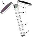
图1为本发明装置的整体结构示意图;Fig. 1 is the overall structure schematic diagram of the device of the present invention;
图2为本发明中薄膜二元光学反射镜组件连接示意图;2 is a schematic diagram of the connection of the thin-film binary optical mirror assembly in the present invention;
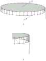
图3为本发明中天线结构示意图;3 is a schematic diagram of an antenna structure in the present invention;
图4为本发明中单个四边形基本桁架示意图;4 is a schematic diagram of a single quadrilateral basic truss in the present invention;
图5为图1收拢结构图;Fig. 5 is the folding structure diagram of Fig. 1;
图6为本发明中薄膜二元光学反射镜组件和馈源位置示意图;6 is a schematic diagram of the position of the thin-film binary optical mirror assembly and the feed source in the present invention;
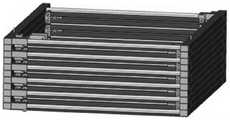
图7为本发明中四边形拉索驱动伸缩桁架收缩态;Fig. 7 is the retracted state of the quadrilateral cable-driven telescopic truss in the present invention;
图8为本发明天线展开过程示意图。FIG. 8 is a schematic diagram of an antenna deployment process of the present invention.
具体实施方式Detailed ways
为了使本发明的用途,技术方案,侧重点及优点表达得更加清楚,下面将结合附图,对本发明实施例中的技术方案进行清楚地描述,显然,所描述的实施例是本发明的一部分实施例,而不是全部的实施例。基于本发明中的实施例,本领域普通技术人员在没有做出创造性劳动的前提下所获得的所有其他实施例,都属于本发明保护的范围。In order to make the use, technical solution, focus and advantages of the present invention more clearly expressed, the technical solutions in the embodiments of the present invention will be clearly described below with reference to the accompanying drawings. Obviously, the described embodiments are part of the present invention. examples, but not all examples. Based on the embodiments of the present invention, all other embodiments obtained by those of ordinary skill in the art without creative work fall within the protection scope of the present invention.
参照图1,本实例设计的光电一体的星载可展开探测装置,包括一对展开天线1、卫星本体2、宽频带馈源3、伸缩桁架4和薄膜二元光学反射镜组件5。其中,卫星本体2的其内部装有后置焦面光学组件和二镜透镜组件;伸缩桁架4采用四边形拉索驱动结构,该四边形拉索驱动伸缩桁架4的顶端与卫星本体2刚性连接,宽频带馈源3,对称分布在四边形拉索驱动伸缩桁架4的两侧;一对展开天线1,对称分布在卫星本体2的两端,其方向与宽频带馈源3相对;薄膜二元光学反射镜组件5安装在四边形拉索驱动伸缩桁架4的底端,用于配合卫星本体内部后置焦面光学组件和二镜透镜组件工作。1 , the optoelectronic integrated spaceborne deployable detection device designed in this example includes a pair of
参照如图2,所述薄膜二元光学反射镜组件5包括二元光学薄膜51与一镜碳纤维支撑架52,该一镜碳纤维支撑架52与四边形拉索驱动伸缩桁架4底端刚性连接,二元光学薄膜51与其周围的一镜碳纤维支撑架52挠性连接,且薄膜二元光学反射镜组件5与宽频带馈源3共口径,共用四边形拉索驱动伸缩桁架基架。Referring to FIG. 2, the thin-film binary
所述一对展开天线1的结构形状可任意选择,如径向肋天线,环柱形天线,张力背架式天线,弹性复原型天线,刚性反射面可展开天线,充气式天线等几种常用可展开天线的结构。本实例采用但不限于最经典的美国ASTROMESH展开结构,每个展开天线1主要由反射薄膜11和可展桁架12构成,如图3a所示,该可展桁架12包括n根竖杆,2n根横杆及n对可伸缩杆,其中n根据可展桁架的边数进行取值,本实例取但不限于取36,即采用三十六边周边可展桁架结构,这些竖杆中有一根装有驱动电机,且这根竖杆刚性连接有旋转小臂,该旋转小臂铰接旋转大臂,如图3b所示,该旋转大臂与卫星本体铰接。本实例之所以采用这种可展开结构是因为天线大都是放置在卫星整流罩内,随卫星一起发射,而展开态要求的空间太大,所以需要天线可收缩。本实例采用的ASTROMESH结构,其在展开态直径为5m左右,而收拢态只需0.5m左右。The structure and shape of the pair of unfolded
参照图4,所述四边形拉索驱动伸缩桁架4是由若干个四边形基本桁架串联形成,每个四边形基本桁架主要由四块横板,四根竖杆,四个滑块以及四个导滑杆组成,且每个四边形桁架同侧滑块采用线缆副连接,图4中两个A滑块同侧,两个B滑块同侧,最后只驱动最低端两个滑块即可驱动整个四边形拉索驱动伸缩桁架进行伸长。Referring to FIG. 4 , the quadrilateral cable-driven
参照图5,本实例在收拢态下,一对展开天线1对称收拢在卫星2顶端,四边形拉索驱动伸缩桁架4则收拢在卫星2底端,而馈源3则收在四边形拉索驱动伸缩桁架内侧,如图6所示。其中所有四边形基本桁架收缩为一个方盒,如图7所示。Referring to FIG. 5 , in the retracted state of this example, a pair of unfolded
参照图8,本实例的展开结构及过程如下:Referring to Figure 8, the deployment structure and process of this example are as follows:
展开天线和四边形拉索驱动伸缩桁架在卫星发射前呈收拢态,如图8a所示。The unfolded antenna and the quadrilateral cable-driven telescopic truss are in a retracted state before satellite launch, as shown in Figure 8a.
待卫星入轨后,四边形拉索驱动伸缩桁架通过驱动最低端两个滑块伸长,由图6可以看出伸缩桁架四个竖杆在收缩态与导滑杆间隔分布在同一水平面,这也就意味着其在伸长时不会被干涉,在四边形拉索驱动伸缩桁架伸长的同时,馈源转到指定位置,天线展开。天线展开过程为:天线旋转大臂先转到指定位置如图8b所示,然后进行小臂旋转After the satellite is in orbit, the quadrilateral cable drives the telescopic truss to extend by driving the two sliders at the lowest end. It can be seen from Figure 6 that the four vertical rods of the telescopic truss are distributed in the same horizontal plane as the guide rods in the retracted state, which is also It means that it will not be interfered when it is stretched. When the quadrilateral cable drives the telescopic truss to stretch, the feed source turns to the designated position and the antenna expands. The antenna deployment process is as follows: the antenna rotates the big arm to the designated position first, as shown in Figure 8b, and then rotates the small arm
小臂旋转一定角度后的状态如图8c所示,待这对展开天线大臂和小臂旋转到达工作位置后,再通过装有驱动电机的竖杆旁边那根横杆驱动使天线完全展开,呈对称分布的展开态,如图8d所示。The state of the forearm after rotating a certain angle is shown in Figure 8c. After the large arm and forearm of the unfolded antenna are rotated to reach the working position, the antenna is fully unfolded by driving the horizontal rod next to the vertical rod equipped with the driving motor. The unfolded state is symmetrically distributed, as shown in Fig. 8d.
这对天线展开后,对称分布在卫星本体的两端,其方向与宽频带馈源相对,而安装在四边形拉索驱动伸缩桁架底端的薄膜二元光学反射镜组件随着伸缩桁架的伸长和卫星本体底端也产生了10m的高度差,而这个高度差是由二元光学薄膜焦距确定的,该高度差可通过更改串联四边形基本桁架的数量来改变。四边形拉索驱动伸缩桁架4在伸长后的工作台状态高度和收缩态高度比值为20:1。本实例设计的四边形拉索驱动伸缩桁架伸长态的高度为10m,但不限于10,收缩态高度为0.5m。After the pair of antennas are unfolded, they are symmetrically distributed at both ends of the satellite body, and their directions are opposite to the broadband feed. A height difference of 10m is also generated at the bottom of the satellite body, and this height difference is determined by the focal length of the binary optical film. The height difference can be changed by changing the number of the basic trusses of the series quadrilateral. The ratio of the height of the worktable state after the extension of the quadrilateral cable-driven
本实例的工作原理为光学系统和天线系统协同探测,且两者探测互不干扰,光学系统利用物体的光谱辐射特性,而天线利用物体具有发射和反射电磁波的能力。但因光学系统受天气和气候因素影响较大,只能在夜晚和没有云雨雾的气候条件下进行探测。某些类型的空间目标,因为天光地影的影响有较长时间的光学不可见期,这也限制了光学系统的应用。而射电天线是一种主动探测设备,通过主动发射电磁波,接收目标回波信号进行探测测和识别,射电天线可以全天时、全天候工作。通过光学系统和天线系统两者协同探测就能更好发挥各自优势,提高探测效果,即在探测过程中天线系统提供光学系统跟踪所需的指向数据,而光学系统主要完成对空间目标的跟踪、精确定位与识别。在满足光学系统工作的条件下,两系统数据互通。在不满足光学系统探测的条件下,天线系统也能独立完成探测工作,且此次设计展开天线呈对称分布,覆盖范围广。值得注意的是,本实例经过薄膜二元光学反射镜透射到地球表面的光和天线反射的电磁波平行,天线系统和光学系统通过对同一目标进行探测,然后信息互通,可提高探测识别能力。通过天线系统和光学系统的结合,充分发挥了天基平台的优势,将光学系统和天线优势互补,可获取目标光学、红外、射电等多波段信息。The working principle of this example is that the optical system and the antenna system cooperate in detection, and the two detections do not interfere with each other. The optical system uses the spectral radiation characteristics of the object, and the antenna uses the object's ability to emit and reflect electromagnetic waves. However, because the optical system is greatly affected by weather and climate factors, it can only be detected at night and in climatic conditions without clouds, rain and fog. Some types of space targets have a long optical invisible period due to the influence of sky, light and earth, which also limits the application of optical systems. The radio antenna is an active detection device. By actively transmitting electromagnetic waves and receiving target echo signals for detection, detection and identification, the radio antenna can work all day and all day. Through the coordinated detection of the optical system and the antenna system, they can better exert their respective advantages and improve the detection effect, that is, the antenna system provides the pointing data required for the tracking of the optical system during the detection process, and the optical system mainly completes the tracking of space targets, Precise location and identification. Under the condition that the optical system works, the data of the two systems can communicate with each other. Under the condition that the detection of the optical system is not satisfied, the antenna system can also complete the detection work independently, and the designed and deployed antennas are symmetrically distributed and have a wide coverage. It is worth noting that in this example, the light transmitted to the earth's surface through the thin-film binary optical mirror is parallel to the electromagnetic wave reflected by the antenna. The antenna system and the optical system can detect the same target and then exchange information, which can improve the detection and identification ability. Through the combination of the antenna system and the optical system, the advantages of the space-based platform are fully utilized, and the advantages of the optical system and the antenna are complemented to obtain the target optical, infrared, radio and other multi-band information.
本实例的单个天线设计口径为5m,形面精度优于2mm,工作频段为从UHF到L频段,假设天线在500km近地轨道,工作频率0.2GHz,则其单个天线覆盖区域直径为188.75km,增益为18dB,若工作频率2.7GHz,则单个天线覆盖区域直径13.75km,增益为42dB,双5m口径射电天线的覆盖面积翻倍,光学薄膜主镜口径1m,光学空间分辨率优于0.15m。The design diameter of a single antenna in this example is 5m, the shape and surface accuracy is better than 2mm, and the working frequency band is from UHF to L frequency band. Assuming that the antenna is in a 500km low-Earth orbit and the working frequency is 0.2GHz, the diameter of the single antenna coverage area is 188.75km. The gain is 18dB. If the operating frequency is 2.7GHz, the diameter of the coverage area of a single antenna is 13.75km, the gain is 42dB, the coverage area of the dual 5m-diameter radio antenna is doubled, the diameter of the optical film primary mirror is 1m, and the optical spatial resolution is better than 0.15m.
以上描述仅是本发明的实施例,不构成对本发明的任何限制,显然对于本领域来说可以对前述实施例所记载的技术方案进行修改,或者对其中部分技术特征进行等同替换,而这些修改或者替换,并不使相应技术方案的本质脱离本发明实施例技术方案精神和范围。The above description is only an embodiment of the present invention, and does not constitute any limitation to the present invention. Obviously, for the art, the technical solutions described in the foregoing embodiments can be modified, or some technical features thereof can be equivalently replaced, and these modifications can be made. Or alternatively, the essence of the corresponding technical solution does not deviate from the spirit and scope of the technical solution of the embodiment of the present invention.
Claims (7)
Translated fromChinesePriority Applications (1)
| Application Number | Priority Date | Filing Date | Title |
|---|---|---|---|
| CN202010316024.3ACN111505614B (en) | 2020-04-21 | 2020-04-21 | Photoelectric integrated satellite-borne deployable detection device |
Applications Claiming Priority (1)
| Application Number | Priority Date | Filing Date | Title |
|---|---|---|---|
| CN202010316024.3ACN111505614B (en) | 2020-04-21 | 2020-04-21 | Photoelectric integrated satellite-borne deployable detection device |
Publications (2)
| Publication Number | Publication Date |
|---|---|
| CN111505614Atrue CN111505614A (en) | 2020-08-07 |
| CN111505614B CN111505614B (en) | 2023-03-24 |
Family
ID=71864234
Family Applications (1)
| Application Number | Title | Priority Date | Filing Date |
|---|---|---|---|
| CN202010316024.3AActiveCN111505614B (en) | 2020-04-21 | 2020-04-21 | Photoelectric integrated satellite-borne deployable detection device |
Country Status (1)
| Country | Link |
|---|---|
| CN (1) | CN111505614B (en) |
Cited By (1)
| Publication number | Priority date | Publication date | Assignee | Title |
|---|---|---|---|---|
| CN114019559A (en)* | 2021-11-10 | 2022-02-08 | 北京微纳星空科技有限公司 | X-ray telescope mechanism and satellite |
Citations (4)
| Publication number | Priority date | Publication date | Assignee | Title |
|---|---|---|---|---|
| US20120154585A1 (en)* | 2010-12-15 | 2012-06-21 | Skybox Imaging, Inc. | Integrated antenna system for imaging microsatellites |
| CN110015444A (en)* | 2019-03-29 | 2019-07-16 | 上海卫星工程研究所 | Middle zero dip composition aperture radar satellite configuration of high orbit |
| CN110108303A (en)* | 2019-05-24 | 2019-08-09 | 山东航天电子技术研究所 | A kind of in-orbit Space Object Detection identification analogue system and method |
| CN110749973A (en)* | 2019-11-30 | 2020-02-04 | 中国人民解放军战略支援部队航天工程大学 | Conformal structure of optical imaging satellite |
- 2020
- 2020-04-21CNCN202010316024.3Apatent/CN111505614B/enactiveActive
Patent Citations (4)
| Publication number | Priority date | Publication date | Assignee | Title |
|---|---|---|---|---|
| US20120154585A1 (en)* | 2010-12-15 | 2012-06-21 | Skybox Imaging, Inc. | Integrated antenna system for imaging microsatellites |
| CN110015444A (en)* | 2019-03-29 | 2019-07-16 | 上海卫星工程研究所 | Middle zero dip composition aperture radar satellite configuration of high orbit |
| CN110108303A (en)* | 2019-05-24 | 2019-08-09 | 山东航天电子技术研究所 | A kind of in-orbit Space Object Detection identification analogue system and method |
| CN110749973A (en)* | 2019-11-30 | 2020-02-04 | 中国人民解放军战略支援部队航天工程大学 | Conformal structure of optical imaging satellite |
Non-Patent Citations (1)
| Title |
|---|
| 王雪瑶: "国外空间目标探测与识别系统发展现状研究", 《航天器工程》* |
Cited By (1)
| Publication number | Priority date | Publication date | Assignee | Title |
|---|---|---|---|---|
| CN114019559A (en)* | 2021-11-10 | 2022-02-08 | 北京微纳星空科技有限公司 | X-ray telescope mechanism and satellite |
Also Published As
| Publication number | Publication date |
|---|---|
| CN111505614B (en) | 2023-03-24 |
Similar Documents
| Publication | Publication Date | Title |
|---|---|---|
| Yujiri et al. | Passive millimeter wave imaging | |
| JP2783522B2 (en) | Satellite focal plane array imager | |
| Appleby | Passive millimetre–wave imaging and how it differs from terahertz imaging | |
| JP6550073B2 (en) | Radar satellite and radar satellite system using the same | |
| US9573702B1 (en) | Deployed radar panel for space situational awareness | |
| CN110275140B (en) | Satellite-borne SAR beam scanning method based on parabolic antenna | |
| KR20200031095A (en) | Phased array antennas and devices that combine these phased array antennas | |
| CN118921105A (en) | Space-based space target super-resolution imaging and ranging communication integrated system | |
| Rahmat-Samii et al. | A history of reflector antenna development: past, present and future | |
| US9559427B2 (en) | Hybrid image gathering systems, satellite system, and related methods | |
| CN111505614B (en) | Photoelectric integrated satellite-borne deployable detection device | |
| Futatsumori et al. | Design and measurement of W-band offset stepped parabolic reflector antennas for airport surface foreign object debris detection radar systems | |
| Yujiri et al. | Passive millimeter-wave video camera | |
| Ishiguro | Japanese large millimeter and submillimeter array | |
| CN102519596A (en) | High-resolution interference spectrum imaging system of geostationary orbit | |
| KR20200105060A (en) | Multi band aperture synthetic aperture radar system | |
| Yeap | Performance analysis of paraboloidal reflector antennas in radio telescopes | |
| US12006070B2 (en) | Method and apparatus for space-based collection and use of photonic power | |
| Suzuki et al. | Overview of ALOS-2 and ALOS-3 | |
| Werth et al. | Ground-based optical imaging of geo satellites with a rotating structure in a sparse aperture array | |
| CN119996836B (en) | Spaceborne omnidirectional staring imaging system and method | |
| Gleed et al. | Operational issues for passive millimeter-wave imaging systems | |
| KR20200061018A (en) | Synthetic aperture radar system | |
| WO2022245772A1 (en) | Method and apparatus for space-based collection and use of photonic power | |
| You et al. | Microwave Remote Sensing Satellite Payload Antenna |
Legal Events
| Date | Code | Title | Description |
|---|---|---|---|
| PB01 | Publication | ||
| PB01 | Publication | ||
| SE01 | Entry into force of request for substantive examination | ||
| SE01 | Entry into force of request for substantive examination | ||
| GR01 | Patent grant | ||
| GR01 | Patent grant |