CN111505553B - Magnetic resonance imaging system and method - Google Patents
Magnetic resonance imaging system and methodDownload PDFInfo
- Publication number
- CN111505553B CN111505553BCN202010327688.XACN202010327688ACN111505553BCN 111505553 BCN111505553 BCN 111505553BCN 202010327688 ACN202010327688 ACN 202010327688ACN 111505553 BCN111505553 BCN 111505553B
- Authority
- CN
- China
- Prior art keywords
- echo signals
- subject
- signal
- echo
- repetition
- Prior art date
- Legal status (The legal status is an assumption and is not a legal conclusion. Google has not performed a legal analysis and makes no representation as to the accuracy of the status listed.)
- Active
Links
Images


Classifications
- G—PHYSICS
- G01—MEASURING; TESTING
- G01R—MEASURING ELECTRIC VARIABLES; MEASURING MAGNETIC VARIABLES
- G01R33/00—Arrangements or instruments for measuring magnetic variables
- G01R33/20—Arrangements or instruments for measuring magnetic variables involving magnetic resonance
- G01R33/44—Arrangements or instruments for measuring magnetic variables involving magnetic resonance using nuclear magnetic resonance [NMR]
- G01R33/48—NMR imaging systems
- G01R33/4808—Multimodal MR, e.g. MR combined with positron emission tomography [PET], MR combined with ultrasound or MR combined with computed tomography [CT]
- G01R33/4812—MR combined with X-ray or computed tomography [CT]
- G—PHYSICS
- G01—MEASURING; TESTING
- G01R—MEASURING ELECTRIC VARIABLES; MEASURING MAGNETIC VARIABLES
- G01R33/00—Arrangements or instruments for measuring magnetic variables
- G01R33/20—Arrangements or instruments for measuring magnetic variables involving magnetic resonance
- G01R33/44—Arrangements or instruments for measuring magnetic variables involving magnetic resonance using nuclear magnetic resonance [NMR]
- G01R33/48—NMR imaging systems
- G01R33/54—Signal processing systems, e.g. using pulse sequences ; Generation or control of pulse sequences; Operator console
- G01R33/56—Image enhancement or correction, e.g. subtraction or averaging techniques, e.g. improvement of signal-to-noise ratio and resolution
- G01R33/563—Image enhancement or correction, e.g. subtraction or averaging techniques, e.g. improvement of signal-to-noise ratio and resolution of moving material, e.g. flow contrast angiography
- A—HUMAN NECESSITIES
- A61—MEDICAL OR VETERINARY SCIENCE; HYGIENE
- A61B—DIAGNOSIS; SURGERY; IDENTIFICATION
- A61B5/00—Measuring for diagnostic purposes; Identification of persons
- A61B5/05—Detecting, measuring or recording for diagnosis by means of electric currents or magnetic fields; Measuring using microwaves or radio waves
- A61B5/055—Detecting, measuring or recording for diagnosis by means of electric currents or magnetic fields; Measuring using microwaves or radio waves involving electronic [EMR] or nuclear [NMR] magnetic resonance, e.g. magnetic resonance imaging
- A—HUMAN NECESSITIES
- A61—MEDICAL OR VETERINARY SCIENCE; HYGIENE
- A61B—DIAGNOSIS; SURGERY; IDENTIFICATION
- A61B5/00—Measuring for diagnostic purposes; Identification of persons
- A61B5/02—Detecting, measuring or recording for evaluating the cardiovascular system, e.g. pulse, heart rate, blood pressure or blood flow
- A61B5/026—Measuring blood flow
- A61B5/0263—Measuring blood flow using NMR
- A—HUMAN NECESSITIES
- A61—MEDICAL OR VETERINARY SCIENCE; HYGIENE
- A61B—DIAGNOSIS; SURGERY; IDENTIFICATION
- A61B5/00—Measuring for diagnostic purposes; Identification of persons
- A61B5/48—Other medical applications
- A61B5/4869—Determining body composition
- A61B5/4872—Body fat
- G—PHYSICS
- G01—MEASURING; TESTING
- G01R—MEASURING ELECTRIC VARIABLES; MEASURING MAGNETIC VARIABLES
- G01R33/00—Arrangements or instruments for measuring magnetic variables
- G01R33/20—Arrangements or instruments for measuring magnetic variables involving magnetic resonance
- G01R33/44—Arrangements or instruments for measuring magnetic variables involving magnetic resonance using nuclear magnetic resonance [NMR]
- G01R33/48—NMR imaging systems
- G01R33/4808—Multimodal MR, e.g. MR combined with positron emission tomography [PET], MR combined with ultrasound or MR combined with computed tomography [CT]
- G01R33/481—MR combined with positron emission tomography [PET] or single photon emission computed tomography [SPECT]
- G—PHYSICS
- G01—MEASURING; TESTING
- G01R—MEASURING ELECTRIC VARIABLES; MEASURING MAGNETIC VARIABLES
- G01R33/00—Arrangements or instruments for measuring magnetic variables
- G01R33/20—Arrangements or instruments for measuring magnetic variables involving magnetic resonance
- G01R33/44—Arrangements or instruments for measuring magnetic variables involving magnetic resonance using nuclear magnetic resonance [NMR]
- G01R33/48—NMR imaging systems
- G01R33/54—Signal processing systems, e.g. using pulse sequences ; Generation or control of pulse sequences; Operator console
- G01R33/56—Image enhancement or correction, e.g. subtraction or averaging techniques, e.g. improvement of signal-to-noise ratio and resolution
- G01R33/5608—Data processing and visualization specially adapted for MR, e.g. for feature analysis and pattern recognition on the basis of measured MR data, segmentation of measured MR data, edge contour detection on the basis of measured MR data, for enhancing measured MR data in terms of signal-to-noise ratio by means of noise filtering or apodization, for enhancing measured MR data in terms of resolution by means for deblurring, windowing, zero filling, or generation of gray-scaled images, colour-coded images or images displaying vectors instead of pixels
- G—PHYSICS
- G01—MEASURING; TESTING
- G01R—MEASURING ELECTRIC VARIABLES; MEASURING MAGNETIC VARIABLES
- G01R33/00—Arrangements or instruments for measuring magnetic variables
- G01R33/20—Arrangements or instruments for measuring magnetic variables involving magnetic resonance
- G01R33/44—Arrangements or instruments for measuring magnetic variables involving magnetic resonance using nuclear magnetic resonance [NMR]
- G01R33/48—NMR imaging systems
- G01R33/54—Signal processing systems, e.g. using pulse sequences ; Generation or control of pulse sequences; Operator console
- G01R33/56—Image enhancement or correction, e.g. subtraction or averaging techniques, e.g. improvement of signal-to-noise ratio and resolution
- G01R33/561—Image enhancement or correction, e.g. subtraction or averaging techniques, e.g. improvement of signal-to-noise ratio and resolution by reduction of the scanning time, i.e. fast acquiring systems, e.g. using echo-planar pulse sequences
- G01R33/5615—Echo train techniques involving acquiring plural, differently encoded, echo signals after one RF excitation, e.g. using gradient refocusing in echo planar imaging [EPI], RF refocusing in rapid acquisition with relaxation enhancement [RARE] or using both RF and gradient refocusing in gradient and spin echo imaging [GRASE]
- G01R33/5616—Echo train techniques involving acquiring plural, differently encoded, echo signals after one RF excitation, e.g. using gradient refocusing in echo planar imaging [EPI], RF refocusing in rapid acquisition with relaxation enhancement [RARE] or using both RF and gradient refocusing in gradient and spin echo imaging [GRASE] using gradient refocusing, e.g. EPI
- G—PHYSICS
- G16—INFORMATION AND COMMUNICATION TECHNOLOGY [ICT] SPECIALLY ADAPTED FOR SPECIFIC APPLICATION FIELDS
- G16H—HEALTHCARE INFORMATICS, i.e. INFORMATION AND COMMUNICATION TECHNOLOGY [ICT] SPECIALLY ADAPTED FOR THE HANDLING OR PROCESSING OF MEDICAL OR HEALTHCARE DATA
- G16H30/00—ICT specially adapted for the handling or processing of medical images
- G16H30/20—ICT specially adapted for the handling or processing of medical images for handling medical images, e.g. DICOM, HL7 or PACS
- G—PHYSICS
- G16—INFORMATION AND COMMUNICATION TECHNOLOGY [ICT] SPECIALLY ADAPTED FOR SPECIFIC APPLICATION FIELDS
- G16H—HEALTHCARE INFORMATICS, i.e. INFORMATION AND COMMUNICATION TECHNOLOGY [ICT] SPECIALLY ADAPTED FOR THE HANDLING OR PROCESSING OF MEDICAL OR HEALTHCARE DATA
- G16H30/00—ICT specially adapted for the handling or processing of medical images
- G16H30/40—ICT specially adapted for the handling or processing of medical images for processing medical images, e.g. editing
- A—HUMAN NECESSITIES
- A61—MEDICAL OR VETERINARY SCIENCE; HYGIENE
- A61B—DIAGNOSIS; SURGERY; IDENTIFICATION
- A61B2576/00—Medical imaging apparatus involving image processing or analysis
- A61B2576/02—Medical imaging apparatus involving image processing or analysis specially adapted for a particular organ or body part
- A61B2576/023—Medical imaging apparatus involving image processing or analysis specially adapted for a particular organ or body part for the heart
- A—HUMAN NECESSITIES
- A61—MEDICAL OR VETERINARY SCIENCE; HYGIENE
- A61B—DIAGNOSIS; SURGERY; IDENTIFICATION
- A61B5/00—Measuring for diagnostic purposes; Identification of persons
- A61B5/48—Other medical applications
- A61B5/4869—Determining body composition
- A61B5/4875—Hydration status, fluid retention of the body
- G—PHYSICS
- G01—MEASURING; TESTING
- G01R—MEASURING ELECTRIC VARIABLES; MEASURING MAGNETIC VARIABLES
- G01R33/00—Arrangements or instruments for measuring magnetic variables
- G01R33/20—Arrangements or instruments for measuring magnetic variables involving magnetic resonance
- G01R33/44—Arrangements or instruments for measuring magnetic variables involving magnetic resonance using nuclear magnetic resonance [NMR]
- G01R33/48—NMR imaging systems
- G01R33/4828—Resolving the MR signals of different chemical species, e.g. water-fat imaging
- G—PHYSICS
- G01—MEASURING; TESTING
- G01R—MEASURING ELECTRIC VARIABLES; MEASURING MAGNETIC VARIABLES
- G01R33/00—Arrangements or instruments for measuring magnetic variables
- G01R33/20—Arrangements or instruments for measuring magnetic variables involving magnetic resonance
- G01R33/44—Arrangements or instruments for measuring magnetic variables involving magnetic resonance using nuclear magnetic resonance [NMR]
- G01R33/48—NMR imaging systems
- G01R33/50—NMR imaging systems based on the determination of relaxation times, e.g. T1 measurement by IR sequences; T2 measurement by multiple-echo sequences
- G—PHYSICS
- G01—MEASURING; TESTING
- G01R—MEASURING ELECTRIC VARIABLES; MEASURING MAGNETIC VARIABLES
- G01R33/00—Arrangements or instruments for measuring magnetic variables
- G01R33/20—Arrangements or instruments for measuring magnetic variables involving magnetic resonance
- G01R33/44—Arrangements or instruments for measuring magnetic variables involving magnetic resonance using nuclear magnetic resonance [NMR]
- G01R33/48—NMR imaging systems
- G01R33/54—Signal processing systems, e.g. using pulse sequences ; Generation or control of pulse sequences; Operator console
- G01R33/56—Image enhancement or correction, e.g. subtraction or averaging techniques, e.g. improvement of signal-to-noise ratio and resolution
- G01R33/5602—Image enhancement or correction, e.g. subtraction or averaging techniques, e.g. improvement of signal-to-noise ratio and resolution by filtering or weighting based on different relaxation times within the sample, e.g. T1 weighting using an inversion pulse
- G—PHYSICS
- G01—MEASURING; TESTING
- G01R—MEASURING ELECTRIC VARIABLES; MEASURING MAGNETIC VARIABLES
- G01R33/00—Arrangements or instruments for measuring magnetic variables
- G01R33/20—Arrangements or instruments for measuring magnetic variables involving magnetic resonance
- G01R33/44—Arrangements or instruments for measuring magnetic variables involving magnetic resonance using nuclear magnetic resonance [NMR]
- G01R33/48—NMR imaging systems
- G01R33/54—Signal processing systems, e.g. using pulse sequences ; Generation or control of pulse sequences; Operator console
- G01R33/56—Image enhancement or correction, e.g. subtraction or averaging techniques, e.g. improvement of signal-to-noise ratio and resolution
- G01R33/561—Image enhancement or correction, e.g. subtraction or averaging techniques, e.g. improvement of signal-to-noise ratio and resolution by reduction of the scanning time, i.e. fast acquiring systems, e.g. using echo-planar pulse sequences
- G01R33/5611—Parallel magnetic resonance imaging, e.g. sensitivity encoding [SENSE], simultaneous acquisition of spatial harmonics [SMASH], unaliasing by Fourier encoding of the overlaps using the temporal dimension [UNFOLD], k-t-broad-use linear acquisition speed-up technique [k-t-BLAST], k-t-SENSE
- G—PHYSICS
- G01—MEASURING; TESTING
- G01R—MEASURING ELECTRIC VARIABLES; MEASURING MAGNETIC VARIABLES
- G01R33/00—Arrangements or instruments for measuring magnetic variables
- G01R33/20—Arrangements or instruments for measuring magnetic variables involving magnetic resonance
- G01R33/44—Arrangements or instruments for measuring magnetic variables involving magnetic resonance using nuclear magnetic resonance [NMR]
- G01R33/48—NMR imaging systems
- G01R33/54—Signal processing systems, e.g. using pulse sequences ; Generation or control of pulse sequences; Operator console
- G01R33/56—Image enhancement or correction, e.g. subtraction or averaging techniques, e.g. improvement of signal-to-noise ratio and resolution
- G01R33/561—Image enhancement or correction, e.g. subtraction or averaging techniques, e.g. improvement of signal-to-noise ratio and resolution by reduction of the scanning time, i.e. fast acquiring systems, e.g. using echo-planar pulse sequences
- G01R33/5615—Echo train techniques involving acquiring plural, differently encoded, echo signals after one RF excitation, e.g. using gradient refocusing in echo planar imaging [EPI], RF refocusing in rapid acquisition with relaxation enhancement [RARE] or using both RF and gradient refocusing in gradient and spin echo imaging [GRASE]
- G01R33/5617—Echo train techniques involving acquiring plural, differently encoded, echo signals after one RF excitation, e.g. using gradient refocusing in echo planar imaging [EPI], RF refocusing in rapid acquisition with relaxation enhancement [RARE] or using both RF and gradient refocusing in gradient and spin echo imaging [GRASE] using RF refocusing, e.g. RARE
- G—PHYSICS
- G01—MEASURING; TESTING
- G01R—MEASURING ELECTRIC VARIABLES; MEASURING MAGNETIC VARIABLES
- G01R33/00—Arrangements or instruments for measuring magnetic variables
- G01R33/20—Arrangements or instruments for measuring magnetic variables involving magnetic resonance
- G01R33/44—Arrangements or instruments for measuring magnetic variables involving magnetic resonance using nuclear magnetic resonance [NMR]
- G01R33/48—NMR imaging systems
- G01R33/54—Signal processing systems, e.g. using pulse sequences ; Generation or control of pulse sequences; Operator console
- G01R33/56—Image enhancement or correction, e.g. subtraction or averaging techniques, e.g. improvement of signal-to-noise ratio and resolution
- G01R33/563—Image enhancement or correction, e.g. subtraction or averaging techniques, e.g. improvement of signal-to-noise ratio and resolution of moving material, e.g. flow contrast angiography
- G01R33/5635—Angiography, e.g. contrast-enhanced angiography [CE-MRA] or time-of-flight angiography [TOF-MRA]
Landscapes
- Health & Medical Sciences (AREA)
- Physics & Mathematics (AREA)
- Nuclear Medicine, Radiotherapy & Molecular Imaging (AREA)
- Engineering & Computer Science (AREA)
- General Health & Medical Sciences (AREA)
- Life Sciences & Earth Sciences (AREA)
- Radiology & Medical Imaging (AREA)
- High Energy & Nuclear Physics (AREA)
- Condensed Matter Physics & Semiconductors (AREA)
- General Physics & Mathematics (AREA)
- Public Health (AREA)
- Medical Informatics (AREA)
- Pathology (AREA)
- Animal Behavior & Ethology (AREA)
- Biophysics (AREA)
- Veterinary Medicine (AREA)
- Biomedical Technology (AREA)
- Heart & Thoracic Surgery (AREA)
- Molecular Biology (AREA)
- Surgery (AREA)
- Theoretical Computer Science (AREA)
- Signal Processing (AREA)
- Pulmonology (AREA)
- Primary Health Care (AREA)
- Epidemiology (AREA)
- Vascular Medicine (AREA)
- Artificial Intelligence (AREA)
- Computer Vision & Pattern Recognition (AREA)
- Physiology (AREA)
- Cardiology (AREA)
- Hematology (AREA)
- Magnetic Resonance Imaging Apparatus (AREA)
Abstract
Translated fromChinese
Description
Translated fromChinese技术领域technical field
本发明涉及磁共振成像技术领域,特别是涉及在磁共振成像中对受试者执行检测的系统和方法。The present invention relates to the technical field of magnetic resonance imaging, in particular to a system and method for performing detection on a subject in magnetic resonance imaging.
背景技术Background technique
磁共振成像系统利用强大的磁场和射频技术而被广泛应用于医学诊断和/或治疗中。在对受试者进行医疗诊断和/或治疗期间,需要对所述受试者进行多种检测,为疾病诊断和/或治疗提供依据,例如纵向弛豫时间(T1)检测、横向弛豫时间(T2)检测、质子密度(PD)检测、B0场检测等。通常地,将多个MR脉冲序列应用于所述受试者以获取不同检测方式的不同MR数据集,然而此种方法效率低,而且会对所述受试者造成不必要的辐射。因此,亟需提供一种有效的系统和方法来收集适用于各种检测的MR数据和/或基于所收集的MR数据对受试者执行检测。Magnetic resonance imaging systems are widely used in medical diagnosis and/or treatment utilizing powerful magnetic fields and radio frequency technology. During the medical diagnosis and/or treatment of the subject, it is necessary to perform various tests on the subject to provide a basis for disease diagnosis and/or treatment, such as longitudinal relaxation time (T1) detection, transverse relaxation time (T2) detection, proton density (PD) detection, B0 field detection, etc. Usually, multiple MR pulse sequences are applied to the subject to obtain different MR data sets with different detection modalities, however, this method is inefficient and causes unnecessary radiation to the subject. Therefore, there is an urgent need to provide an effective system and method for collecting MR data suitable for various tests and/or performing tests on a subject based on the collected MR data.
发明内容Contents of the invention
根据本发明的一个方面,提供了一种系统。该系统可以包括至少一个存储设备,其存储用于MRI的一组指令;以及至少一个处理器,用于与所述至少一个存储设备通信,其中,当执行所述指令时,所述至少一个处理器可以用于指示所述系统执行以下操作。所述至少一个处理器可以用于指示所述系统获取与受试者相关的第一组回波信号和第二组回波信号。所述第一组回波信号是通过采用MR扫描仪对所述受试者进行第一采集生成,所述第二组回波信号是通过采用所述MR扫描仪对所述受试者进行第二采集生成。所述第一采集可以包括具有不同重复时间的至少第一重复过程和第二重复过程。每一个所述第一重复过程和所述第二重复过程可以均具有第一翻转角度。所述第二采集可以包括具有不同重复时间的至少第三重复过程和第四重复过程。每一个所述第三重复过程和所述第四重复过程可以均具有与所述第一翻转角度不同的第二翻转角度。所述至少一个处理器还可用于指示所述系统基于所述第一组回波信号或所述第二组回波信号中的至少一个回波信号对所述受试者执行检测。According to one aspect of the invention, a system is provided. The system may include at least one storage device storing a set of instructions for MRI; and at least one processor configured to communicate with the at least one storage device, wherein, when executing the instructions, the at least one processing can be used to instruct the system to perform the following operations. The at least one processor may be operable to instruct the system to acquire a first set of echo signals and a second set of echo signals associated with a subject. The first group of echo signals is generated by using the MR scanner to perform the first acquisition on the subject, and the second group of echo signals is generated by using the MR scanner to perform the first acquisition on the subject. Two acquisition generation. The first acquisition may comprise at least a first repetition and a second repetition having different repetition times. Each of the first repetition process and the second repetition process may have a first flip angle. The second acquisition may include at least a third and a fourth repetition with different repetition times. Each of the third and fourth iterations may have a second flip angle different from the first flip angle. The at least one processor is further operable to instruct the system to perform detection on the subject based on at least one echo signal of the first set of echo signals or the second set of echo signals.
根据本发明的另一方面,提供了一种在具备至少一个处理器和至少一个存储设备的计算机设备上实现MRI的方法。所述方法可以包括获取与受试者相关的第一组回波信号和第二组回波信号,以及基于所述第一组回波信号或所述第二组回波信号中的至少一个对所述受试者执行检测,其中通过采用MR扫描仪对所述受试者进行第一采集,以生成所述第一组回波信号,通过采用所述MR扫描仪对所述受试者进行第二采集,以生成所述第二组回波信号,所述第一采集可以至少包括具有不同重复时间的第一重复过程和第二重复过程,每一个所述第一重复过程和每一个所述第二重复过程可以均具有第一翻转角;所述第二采集可以至少包括具有不同重复时间的第三重复过程和第四重复过程,每一个所述第三重复过程和每一个所述第四重复过程可以均具有与所述第一翻转角不同的第二翻转角。According to another aspect of the present invention, there is provided a method of implementing MRI on a computer device having at least one processor and at least one storage device. The method may include obtaining a first set of echo signals and a second set of echo signals associated with the subject, and matching a first set of echo signals based on at least one of the first set of echo signals The subject performs a test, wherein a first acquisition is performed on the subject by using an MR scanner to generate the first set of echo signals, and the test is performed on the subject by using the MR scanner second acquisition, to generate the second group of echo signals, the first acquisition may at least include a first repetition process and a second repetition process with different repetition times, each of the first repetition process and each of the The second repeating process may both have a first flip angle; the second acquisition may at least include a third repeating process and a fourth repeating process with different repeating times, each of the third repeating process and each of the first The four iterations may each have a second flip angle different from the first flip angle.
根据本发明的另一方面,提供了存储用于MRI的指令的非暂时性计算机可读介质。当由系统的至少一个处理器访问时,所述指令可以使系统执行方法。所述方法可以包括获取与受试者相关的第一组回波信号和第二组回波信号;以及基于所述第一组回波信号或所述第二组回波信号中的至少一个对所述受试者执行检测,其中,通过采用MR扫描仪对所述受试者进行第一采集,以生成所述第一组回波信号,通过采用所述MR扫描仪对所述受试者进行第二采集,以生成所述第二组回波信号,所述第一采集可以至少包括具有不同重复时间的第一重复过程和第二重复过程,每一个所述第一重复过程和每一个所述第二重复过程可以均具有第一翻转角;所述第二采集可以至少包括具有不同重复时间的第三重复过程和第四重复过程,每一个所述第三重复过程和每一个所述第四重复过程可以均具有与所述第一翻转角不同的第二翻转角。According to another aspect of the invention, a non-transitory computer readable medium storing instructions for MRI is provided. The instructions, when accessed by at least one processor of the system, cause the system to perform the method. The method may include acquiring a first set of echo signals and a second set of echo signals associated with a subject; and matching based on at least one of the first set of echo signals or the second set of echo signals The subject performs a test, wherein a first acquisition is performed on the subject by using an MR scanner to generate the first set of echo signals, and the test is performed on the subject by using the MR scanner performing a second acquisition to generate the second set of echo signals, the first acquisition may at least include a first repetition process and a second repetition process with different repetition times, each of the first repetition process and each The second repetition process may each have a first flip angle; the second collection may at least include a third repetition process and a fourth repetition process with different repetition times, each of the third repetition process and each of the The fourth iterations may each have a second flip angle different from the first flip angle.
本发明的附加特征将在下面的描述中部分阐述,并且本领域技术人员在查阅下述内容和附图,或者通过示例进行实际操作或验证后,可以容易理解附加特征。本发明的特征可以通过实践或使用下面讨论的详细示例中阐述的方法、工具和其组合来实现。The additional features of the present invention will be partly explained in the following descriptions, and those skilled in the art can easily understand the additional features after referring to the following content and drawings, or performing actual operation or verification through examples. The features of the invention can be realized by practice or use of the methods, means and combinations thereof set forth in the detailed examples discussed below.
附图说明Description of drawings
本发明还通过多个示例性实施例进一步描述本发明,参考附图详细描述这些示例性实施例。这些实施例是非限制性的示例性实施例,其中类似的附图标记在附图的多个视图中表示类似的结构,其中:The present invention is further described by a number of exemplary embodiments, which are described in detail with reference to the accompanying drawings. These embodiments are non-limiting exemplary embodiments, wherein like reference numerals indicate like structures throughout the several views of the drawings, wherein:
图1为根据本发明的一些实施例的示例性MRI系统的示意图;Figure 1 is a schematic diagram of an exemplary MRI system according to some embodiments of the invention;
图2为根据本发明的一些实施例的示例性MR扫描仪的框图;Figure 2 is a block diagram of an exemplary MR scanner according to some embodiments of the invention;
图3为根据本发明的一些实施例的计算设备的示例性硬件和/或软件组件的示意图;3 is a schematic diagram of exemplary hardware and/or software components of a computing device according to some embodiments of the invention;
图4为根据本发明的一些实施例的移动设备的示例性硬件和/或软件组件的示意图;Figure 4 is a schematic diagram of exemplary hardware and/or software components of a mobile device according to some embodiments of the invention;
图5为根据本发明的一些实施例的示例性处理设备的框图;Figure 5 is a block diagram of an exemplary processing device according to some embodiments of the invention;
图6为根据本发明的一些实施例的用于对受试者执行检测的示例性过程的流程图;6 is a flowchart of an exemplary process for performing a test on a subject, according to some embodiments of the invention;
图7至图11为根据本发明的一些实施例的示例性MR脉冲序列;7-11 are exemplary MR pulse sequences according to some embodiments of the present invention;
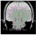
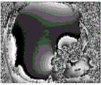
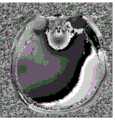
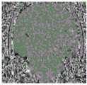
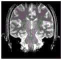
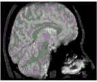
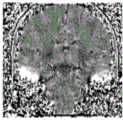
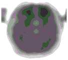
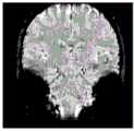
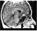
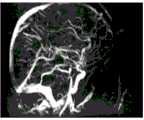
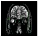
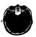
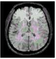
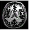
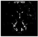
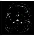
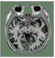
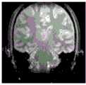
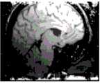
图12A至图41C为根据本发明的一些实施例的患者大脑的示例性检测结果。12A-41C are exemplary detection results of a patient's brain according to some embodiments of the present invention.
具体实施方式Detailed ways
在下面的详细描述中,通过示例阐述了许多具体细节,以便于对相关公开内容进行深入理解。然而,本领域技术人员应当清楚,本发明可以在没有这些细节的情况下实施。在一般情况下,为了避免不必要地混淆,本发明以相对较高的水平描述了众所周知的方法、过程、系统、组件和/或电路,而没有对其详细说明。对于本领域技术人员来说,对所公开的实施例的各种修改将是显而易见的,并且在不脱离本发明的构思和范围的情况下,本发明定义的一般原则可以应用于其他实施例和应用。因此,本发明不限于所列举的实施例,而是涵盖了与权利要求一致的最宽范围。In the following detailed description, many specific details are set forth by way of examples, so as to facilitate an in-depth understanding of the relevant disclosure. It will be apparent, however, to one skilled in the art that the present invention may be practiced without these details. In general, well-known methods, procedures, systems, components and/or circuits have been described herein at a relatively high level rather than in detail in order to avoid unnecessarily obscuring them. Various modifications to the disclosed embodiments will be readily apparent to those skilled in the art, and the generic principles defined herein may be applied to other embodiments and embodiments without departing from the spirit and scope of the invention. application. Accordingly, the present invention is not limited to the exemplified embodiments, but covers the widest scope consistent with the claims.
本发明中使用的术语仅用于描述特定示例实施例,并不旨在限制本发明。如本发明所用,“一”、“一个”以及“一种”可为单数形式,也可以指复数形式,除非上下文另有明确指示。可以进一步理解,术语“包括”和“包含”在本发明中使用时,规定了包括所述特征、整数、步骤、操作、元素和/或组件,但不排除存在或添加一个或多个其他特征、整体、步骤、操作、元件、组件和/或其组合。The terms used in the present invention are for describing specific example embodiments only, and are not intended to limit the present invention. As used in the present invention, "a", "an" and "an" may refer to the singular form or the plural form, unless the context clearly indicates otherwise. It can be further understood that when the terms "comprising" and "comprises" are used in the present invention, they stipulate that the features, integers, steps, operations, elements and/or components are included, but do not exclude the existence or addition of one or more other features. , as a whole, steps, operations, elements, components and/or combinations thereof.
应当理解,本发明中使用的术语“系统”、“单元”、“模块”和/或“块”是一种按升序区分不同级别的不同组件、元件、部件、部分或组件的方式。但是,如果另一种表达方式的其他术语也可达到相同的目的,则这些术语可能会被其取代。It should be understood that the terms "system", "unit", "module" and/or "block" used in the present invention are a way of distinguishing different components, elements, parts, parts or components of different levels in ascending order. However, these terms may be superseded by other terms of another expression if they serve the same purpose.
通常,这里使用的“模块”、“单元”或“块”词语是指硬件或固件中包含的逻辑组件,或指软件指令的集合。本发明描述的模块、单元或块可以用软件和/或硬件来实现,并且可以存储在任何类型的非暂时性计算机可读介质或另一存储设备中。在一些实施例中,软件模块/单元/块可以被编译并链接到可执行程序中。应当理解,软件模块可以从其他模块/单元/块或其自身调用,和/或可以响应检测到的事件或中断而调用。用于在计算设备(例如,如图3所示的处理器310)上执行的软件模块/单元/块可以设置在计算机可读介质上,例如光盘、数字视频光盘、闪存驱动器、磁盘或任何其他有形介质上,或者作为数字下载(并且最初以压缩或可安装的格式存储,在执行之前需要安装、解压缩或解密)。这些软件代码可以部分或全部存储在计算设备的存储设备上,以供计算设备执行。软件指令可以嵌入固件中,例如EPROM(可擦除可编程只读存储器)。进一步可理解,硬件模块/单元/块可以包括所连接的逻辑组件,例如门和触发器,和/或可包括可编程单元,例如可编程门阵列或处理器。本发明描述的模块/单元/块或计算设备功能可以用软件模块/单元/块来实现,但也可以用硬件或固件表示。一般来说,本发明所描述的模块/单元/块是指逻辑模块/单元/块,它们可以与其他模块/单元/块组合,或者尽管它们的物理组织或存储方式不同,但也可以划分为子模块/子单元/子块。其中,该描述可适用于系统、装置或其一部分。In general, the words "module", "unit" or "block" as used herein refer to a logical component contained in hardware or firmware, or to a collection of software instructions. The modules, units or blocks described in the present invention may be implemented in software and/or hardware, and may be stored in any type of non-transitory computer readable medium or another storage device. In some embodiments, a software module/unit/block may be compiled and linked into an executable program. It should be understood that software modules may be called from other modules/units/blocks or themselves and/or may be called in response to detected events or interrupts. A software module/unit/block for execution on a computing device (e.g.,
可以理解,当一个单元、设备、模块或块被称为“开启”、“连接到”或“耦合到”另一个单元、设备、模块或块时,它可以直接开启、连接到、耦合到或通信到另一个单元、设备、模块或块,也可以是可能存在的中间单元、装置、模块或块,除非上下文另有明确说明。如本发明所使用的,术语“和/或”包括一个或多个相关的所列特征的任何和所有组合。本发明中的术语“像素”和“体素”可交替用于指代图像中的元素。本发明中的术语“图像”用于指各种形式的图像,包括二维图像、三维图像、四维图像等。It will be understood that when a unit, device, module or block is referred to as being "on", "connected to" or "coupled to" another unit, device, module or block, it can be directly on, connected to, coupled to or Communicating to another unit, device, module or block, and possibly intervening units, devices, modules or blocks, unless the context clearly dictates otherwise. As used herein, the term "and/or" includes any and all combinations of one or more of the associated listed features. The terms "pixel" and "voxel" in this disclosure are used interchangeably to refer to elements in an image. The term "image" in the present invention is used to refer to various forms of images, including two-dimensional images, three-dimensional images, four-dimensional images, and the like.
此外,虽然本发明中公开的系统和方法主要是描述关于在MRI系统中对受试者(例如,患者,患者的物理点)执行检测。应该理解,这只是为了说明。本发明的系统和方法可应用于任何其他类型的医学成像系统。在一些实施例中,成像系统可以包括单模态成像系统和/或多模态成像系统。单模态成像系统可以包括例如MRI系统。多模态成像系统可以包括,例如,计算机断层-磁共振成像(MRI-CT)系统、正电子发射断层-磁共振成像(PET-MRI)系统、单光子发射计算机断层-磁共振成像(SPECT-MRI)系统,数字减影血管造影-磁共振成像(DSA-MRI)系统等。Furthermore, although the systems and methods disclosed in the present invention are primarily described with respect to performing inspections on a subject (eg, a patient, a physical point of a patient) in an MRI system. It should be understood that this is for illustration only. The systems and methods of the present invention are applicable to any other type of medical imaging system. In some embodiments, the imaging system may include a single modality imaging system and/or a multi-modality imaging system. Single modality imaging systems may include, for example, MRI systems. Multimodal imaging systems may include, for example, computed tomography-magnetic resonance imaging (MRI-CT) systems, positron emission tomography-magnetic resonance imaging (PET-MRI) systems, single-photon emission computed tomography-magnetic resonance imaging (SPECT- MRI) system, digital subtraction angiography-magnetic resonance imaging (DSA-MRI) system, etc.
本发明的一个方面涉及对受试者进行检测的系统和方法。所述系统和方法可以获取与受试者相关的第一组回波信号和第二组回波信号;以及基于所述第一组回波信号或所述第二组回波信号中的至少一个对所述受试者执行检测,其中通过采用MR扫描仪对所述受试者进行第一采集,以生成所述第一组回波信号,通过采用所述MR扫描仪对所述受试者进行第二采集,以生成所述第二组回波信号,所述第一采集可以包括具有不同重复时间的至少第一重复过程和第二重复过程,每一个所述第一重复过程和所述第二重复过程可以均具有第一翻转角;所述第二采集可以包括具有不同重复时间的至少第三重复过程和第四重复过程,每一个所述第三重复过程和所述第四重复过程可以均具有与所述第一翻转角不同的第二翻转角。One aspect of the invention relates to systems and methods for testing a subject. The systems and methods may acquire a first set of echo signals and a second set of echo signals associated with a subject; and based on at least one of the first set of echo signals or the second set of echo signals performing a test on the subject, wherein a first acquisition is performed on the subject by using an MR scanner to generate the first set of echo signals, by using the MR scanner on the subject performing a second acquisition to generate the second set of echo signals, the first acquisition may include at least a first iteration and a second iteration having different repetition times, each of the first iteration and the The second repetition process may each have a first flip angle; the second acquisition may include at least a third repetition process and a fourth repetition process having different repetition times, each of the third repetition process and the fourth repetition process may each have a second flip angle different from the first flip angle.
根据本发明的一些实施例,在至少一次所述第一、第二、第三和第四重复过程期间,可以在多个回波时间中获取多个回波信号。可选地,至少一次所述第一、第二、第三和第四重复过程可以包括流动调制FM模块。如此,在所述受试者的扫描期间,可以获取更多与所述受试者相关的数据,包括对应于不同TE的数据、对应于不同翻转角的数据、对应于FM模块的数据、对应于不同TR的数据,这可以在不延长扫描时间的情况下提高采集效率。此种方式可以允许基于单次扫描同时执行所述受试者的不同检测,减少所述受试者的扫描次数(或计数)以收集用于不同检测的数据,从而减少扫描时间。According to some embodiments of the invention, during at least one of said first, second, third and fourth repetitions, a plurality of echo signals may be acquired in a plurality of echo times. Optionally, at least one of said first, second, third and fourth iterations may include a flow modulation FM module. In this way, during the scanning of the subject, more data related to the subject can be acquired, including data corresponding to different TEs, data corresponding to different flip angles, data corresponding to FM modules, data corresponding to For data with different TRs, this can improve acquisition efficiency without prolonging the scan time. This approach may allow different tests of the subject to be performed simultaneously based on a single scan, reducing the number of scans (or counts) of the subject to collect data for different tests, thereby reducing scan time.
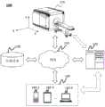
图1是根据本发明的一些实施例的示例性MRI系统100的示意图。如图1所示,所述MRI系统100可以包括MR扫描仪110、处理设备120、存储设备130、一个或多个终端140和网络150。在一些实施例中,所述MR扫描仪110、所述处理设备120、所述存储设备130和/或所述终端140可以通过无线连接、有线连接或其组合彼此连接和/或通信。所述MRI系统100中的组件之间的连接是可变的。例如,所述MR扫描仪110可以通过所述网络150连接到所述处理设备120。在另一实施例中,所述MR扫描仪110可以直接连接到所述处理设备120。FIG. 1 is a schematic diagram of an
所述MR扫描仪110可用于扫描受试者(或所述受试者的一部分)以获取图像数据,例如与所述受试者相关联的回波信号(或MR信号)。例如,所述MR扫描仪110可以通过对所述受试者施加MR脉冲序列来检测多个回波信号。在一些实施例中,所述MR扫描仪110可以包括如图2所示的部件,例如磁性体、梯度线圈、RF线圈等。在一些实施例中,根据磁性体的类型,所述MR扫描仪110可以是永磁MR扫描仪、超导电磁铁MR扫描仪或电阻电磁铁MR扫描仪等。在一些实施例中,根据磁场强度,所述MR扫描仪110可以是高场MR扫描仪、中场MR扫描仪和低场MR扫描仪等。The
所述受试者可以是生物性的或非生物性的。例如,所述受试者可以包括患者、人造物体等。在另一实施例中,所述受试者可以包括患者的特定部分、器官、组织和/或物理点。例如,所述受试者可以包括头部、大脑、颈部、身体、肩部、手臂、胸部、心脏、胃、血管、软组织、膝盖、脚或其他部位等,或其组合。The subject can be biological or abiotic. For example, the subject can include a patient, an artificial object, and the like. In another embodiment, the subject may include a specific part, organ, tissue and/or physical point of a patient. For example, the subject can include the head, brain, neck, body, shoulders, arms, chest, heart, stomach, blood vessels, soft tissue, knees, feet, or other parts, etc., or combinations thereof.
为了便于说明,在图1中提供了包括X轴、Y轴和Z轴的坐标系。图1所示的X轴和Z轴可以是水平的,Y轴可以是垂直的。如图1所示,从面对所述MRI扫描仪110的方向看,沿X轴的正方向可以从所述MRI扫描仪110的右侧到左侧;沿Y轴的正方向可以从所述MRI扫描仪110的下部到上部;沿着Z轴的正方向可以是指所述受试者从所述MRI扫描仪110的扫描通道(或称为管道)中移出的方向。可以在本发明的其它位置找到对所述MRI扫描仪110的更多描述。例如,参见图2及其说明。For convenience of description, a coordinate system including an X axis, a Y axis and a Z axis is provided in FIG. 1 . The X and Z axes shown in FIG. 1 may be horizontal, and the Y axis may be vertical. As shown in Figure 1, viewed from the direction facing the
所述处理设备120可以处理从所述MR扫描仪110、所述存储设备130和/或所述终端140获取的数据和/或信息。例如,所述处理设备120可以通过处理所述MR扫描仪110采集的图像数据(例如,回波信号)生成MR图像。在另一实施例中,所述处理设备120可以基于所述图像数据对所述受试者执行检测。在一些实施例中,所述处理设备120可以是单个服务器或服务器组。所述服务器组可以是集中式或分布式的。在一些实施例中,所述处理设备120可以是本地的或远程的。例如,所述处理设备120可以经由所述网络150访问所述MR扫描仪110、所述存储设备130和/或所述终端140中的信息和/或数据。在另一实施例中,所述处理设备120可以直接连接到所述MR扫描仪110、所述终端140和/或所述存储设备130以访问信息和/或数据。在一些实施例中,所述处理设备120可以在云平台上实现。例如,所述云平台可以包括私有云、公共云、混合云、社区云、分布式云、中间云、多云等,或者其组合。在一些实施例中,所述处理设备120可以通过包括图3所描述的一个或多个组件的计算设备300来实现。The
所述存储设备130可以存储数据、指令和/或任何其他信息。在一些实施例中,所述存储设备130可以存储从所述MR扫描仪110、所述处理设备120和/或所述终端140获得的数据。在一些实施例中,所述存储设备130可以存储数据和/或指令,所述处理设备120可以执行或使用所述数据和/或指令,来执行本发明中描述的示例性方法。在一些实施例中,所述存储设备130可以包括大容量存储设备、可移动存储设备、易失性读写存储器、只读存储器(ROM)等或其组合。举例来说,大容量存储设备可以包括磁盘、光盘、固态驱动器等。举例来说,可移动存储设备可以包括闪存驱动器、软盘、光盘、存储卡、压缩磁盘、磁带等。举例来说,易失性读写存储器可以包括随机存取存储器(RAM)。举例来说,RAM可以包括动态RAM(DRAM)、双倍数据速率同步动态RAM(DDR SDRAM)、静态RAM(SRAM)、晶闸管RAM(T-RAM)、零电容RAM(Z-RAM)等。举例来说,ROM可以包括掩模ROM(MROM)、可编程ROM(PROM)、可擦除可编程ROM(EPROM)、电可擦除可编程ROM(EEPROM)、可擦除可编程ROM(EPROM)、光盘ROM(CD-ROM)、数字多功能磁盘ROM等。在一些实施例中,所述存储设备130可以在如本发明其他部分所述的云平台上实现。The
在一些实施例中,所述存储设备130可以连接到所述网络150以与所述MRI系统100中的一个或多个其他组件(例如所述MR扫描仪110、所述处理设备120和/或所述终端140)通信。所述MRI系统100的一个或多个组件可以经由所述网络150访问所述存储设备130中存储的数据或指令。在一些实施例中,所述存储设备130可以是所述处理设备120或所述终端140的一部分。In some embodiments, the
所述终端140可以允许用户与所述MRI系统100之间的用户交互。例如,所述终端140可以从所述用户接收指令,所述指令使所述MR扫描仪110扫描所述受试者。在另一实施例中,所述终端140可以从所述处理设备120接收处理结果(例如,检测结果,如与所述受试者相关的定量参数值或定量映射),并将所述处理结果显示给用户。在一些实施例中,所述终端140可以与所述MR扫描仪110、所述处理设备120和/或所述存储设备130连接和/或通信。在一些实施例中,所述终端140可以包括移动设备140-1、平板电脑140-2、笔记本电脑140-3等或其组合。例如,移动设备140-1可以包括移动电话、个人数字助理(PDA)、游戏设备、导航设备、销售点(POS)设备、笔记本电脑、平板电脑、台式机电脑等或其组合。在一些实施例中,所述终端140可以包括输入设备、输出设备等。所述输入设备可以包括字母数字键和其他键,这些键可以通过键盘、触摸屏(例如,具备触觉或触觉反馈)、语音输入、眼睛跟踪输入、脑监控系统输入或任何其他类似的输入机制方式进行输入。通过所述输入设备接收的输入信息可以经由例如总线发送到所述处理设备120,以进行进一步处理。其他类型的输入设备可包括光标控制设备,例如鼠标、轨迹球或光标方向键等。所述输出设备可以包括显示器、扬声器、打印机等或其组合。在一些实施例中,所述终端140可以是所述处理设备120或所述MR扫描仪110的一部分。The terminal 140 may allow user interaction with the
所述网络150可以包括能够促进所述MRI系统100的信息和/或数据交换的任何合适网络。在一些实施例中,所述MRI系统100的一个或多个组件(例如所述MR扫描仪110、所述处理设备120、所述存储设备130、所述终端140等)可以经由所述网络150与所述MRI系统100的一个或多个其他组件通信信息和/或数据。例如,所述处理设备120可以经由所述网络150从所述MR扫描仪110获取图像数据(例如,回波信号)。在另一实施例中,所述处理设备120可以经由所述网络150从所述终端140获取用户指令。所述网络150可以包括公共网络(例如因特网)、专用网络(例如局域网(LAN)、广域网(WAN)等)、有线网络(例如以太网)、无线网络(例如802.11网络、Wi-Fi网络等)、蜂窝网络(例如长期演进(LTE)网络),帧中继网络、虚拟专用网络(“VPN”)、卫星网络、电话网络、路由器、集线器、交换机、服务器计算机或其组合。例如,所述网络150可以包括有线电视网络、有线网络、光纤网络、电信网络、内联网、无线局域网(WLAN)、城域网(MAN)、公用电话交换网络(PSTN)、蓝牙TM网络、ZigBeeTM网络、近场通信(NFC)网络等,或其组合。在一些实施例中,所述网络150可以包括一个或多个网络接入点。例如,所述网络150可以包括有线和/或无线网络接入点,例如基站和/或因特网交换点,通过这些接入点,所述MRI系统100的一个或多个组件可以连接到所述网络150以交换数据和/或信息。The
上述描述仅仅是为了解释说明本发明,并不限制本发明的范围。对本领域技术人员来说,许多替代、修改和变化方案都是显而易见的。此处描述的示例性实施例的特征、结构、方法和特性可以以各种方式组合,以获得附加和/或替代的示例性实施例。在一些实施例中,所述MRI系统100可以包括一个或多个附加组件和/或省略上述一个或多个组件。另外可选择地,所述MRI系统100的两个以上组件可以集成到单个组件中。例如,所述处理设备120可以集成到所述MR扫描仪110中。在另一实施例中,所述MRI系统100的组件可以被能够实现该组件的功能的另一组件替换。在一些实施例中,所述存储设备130可以是包括云计算平台的数据存储,例如公共云、私有云、社区和混合云等。然而,这些变化和修改不脱离本发明的范围。The above description is only for explaining the present invention, and does not limit the scope of the present invention. Numerous alternatives, modifications and variations will be apparent to those skilled in the art. The features, structures, methods, and characteristics of the example embodiments described herein can be combined in various ways to obtain additional and/or alternative example embodiments. In some embodiments, the
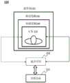
图2是根据本发明的一些实施例的示例性MR扫描仪110的框图。如图2所示,所述MR扫描仪110可以包括磁性体220、梯度线圈230、RF线圈240和脉冲序列模块250。FIG. 2 is a block diagram of an
在扫描受试者210的至少一部分的过程中,所述磁性体220可以产生静态磁场。所述磁性体220可以是各种类型,包括例如永磁体、超导电磁铁、电阻性电磁铁等。During scanning at least a portion of the subject 210, the magnetic body 220 may generate a static magnetic field. The magnetic body 220 can be of various types, including, for example, permanent magnets, superconducting electromagnets, resistive electromagnets, and the like.
所述梯度线圈230可以在X方向、Y方向和/或Z方向上向主磁场提供磁场梯度。如此处所用的,X方向、Y方向和Z方向可以表示坐标系中的X轴、Y轴和Z轴(例如,与图1中所描述的相同或类似的坐标系)。例如,Z轴可以沿着所述磁性体220的轴,X轴和Z轴可以形成水平面,X轴和Y轴可以形成垂直面。在一些实施例中,所述梯度线圈230可以包括用于向X方向的主磁场提供磁场梯度的X方向线圈、用于向Y方向的主磁场提供磁场梯度的Y方向线圈,和/或用于向Z方向的主磁场提供磁场梯度的Z方向线圈。在一些实施例中,所述X方向线圈、所述Y方向线圈和/或所述Z方向线圈可以具备各种形状或配置。例如,所述Z方向线圈可以基于圆形(Maxwell)线圈设计。在另一实施例中,可以根据鞍形(Golay)线圈配置来设计所述X方向线圈和所述Y方向线圈。The gradient coil 230 may provide a magnetic field gradient to the main magnetic field in the X direction, the Y direction and/or the Z direction. As used herein, the X-direction, Y-direction, and Z-direction may refer to the X-axis, Y-axis, and Z-axis in a coordinate system (eg, the same or similar coordinate system as described in FIG. 1 ). For example, the Z axis may be along the axis of the magnetic body 220 , the X axis and the Z axis may form a horizontal plane, and the X and Y axes may form a vertical plane. In some embodiments, the gradient coil 230 may include an X direction coil for providing a magnetic field gradient to the main magnetic field in the X direction, a Y direction coil for providing a magnetic field gradient to the main magnetic field in the Y direction, and/or a coil for A Z-direction coil that provides a magnetic field gradient to the main magnetic field in the Z-direction. In some embodiments, the X-direction coil, the Y-direction coil and/or the Z-direction coil may have various shapes or configurations. For example, the Z-direction coil may be based on a circular (Maxwell) coil design. In another embodiment, the X-direction coil and the Y-direction coil may be designed according to a saddle (Golay) coil configuration.
所述RF线圈240可以向所述受试者210发射RF脉冲信号和/或接收来自所述受试者210的回波信号。在一些实施例中,所述RF线圈240可以包括发射线圈和接收线圈。发射线圈可以发射信号(例如RF脉冲),该信号可以激励所述受试者210中的原子核以产生共振。接收线圈可以接收从所述受试者210发射的回波信号。在一些实施例中,所述RF发射线圈和所述RF接收线圈可以集成到同一个线圈中。在一些实施例中,所述RF线圈240可以是各种类型,包括例如正交检测(简写为QD)线圈、相位阵列线圈、特定元件频谱线圈等。在一些实施例中,所述RF线圈240可以是包括多个线圈单元的相位阵列线圈,每个线圈单元可以独立地检测回波信号。The RF coil 240 can transmit RF pulse signals to the subject 210 and/or receive echo signals from the subject 210 . In some embodiments, the RF coil 240 may include a transmit coil and a receive coil. The transmit coil may emit signals (eg, RF pulses) that may excite atomic nuclei in the subject 210 to resonate. A receiving coil may receive echo signals emitted from the subject 210 . In some embodiments, the RF transmit coil and the RF receive coil may be integrated into the same coil. In some embodiments, the RF coil 240 may be of various types including, for example, quadrature detection (abbreviated as QD) coils, phased array coils, specific element spectral coils, and the like. In some embodiments, the RF coil 240 may be a phase array coil including a plurality of coil units, and each coil unit may independently detect echo signals.
在一些实施例中,所述RF线圈240可用于检测由MR脉冲序列生成的信号。所述MR脉冲序列可以是多种类型,例如自旋回波(简写为SE)脉冲序列、梯度重聚焦回波(简写为GRE)脉冲序列、反转恢复(简写为IR)脉冲序列、多回波MR脉冲序列、T1ρ准备脉冲序列、T2准备脉冲序列、扩散加权成像(简写为DWI)脉冲序列、饱和恢复(简写为SR)脉冲序列、稳态脉冲序列等。如此处所用的,所述多回波MR脉冲序列可以指在每个激励脉冲之后产生(或检测)多个回波的多个信号的脉冲序列。T1ρ准备脉冲序列可以指包括T1ρ加权磁化准备脉冲(也称为自旋锁定脉冲)的脉冲序列。T2准备脉冲序列可以指包括T2准备脉冲的脉冲序列。DWI脉冲序列可以指在脉冲序列前后有一对扩散敏感梯度的脉冲序列(通常为自旋回波序列),例如脉冲序列中的180度脉冲。SR脉冲序列可以指部分饱和脉冲序列,其中前一个脉冲使自旋处于饱和状态,以便在下一个脉冲时从没有磁化的初始条件中恢复。稳态脉冲序列可以指在每次重复中保持纵向磁化和/或横向磁化恒定以达到平衡或稳态的脉冲序列。In some embodiments, the RF coil 240 may be used to detect signals generated by MR pulse sequences. The MR pulse sequence can be of various types, such as spin echo (abbreviated as SE) pulse sequence, gradient refocusing echo (abbreviated as GRE) pulse sequence, inversion recovery (abbreviated as IR) pulse sequence, multi-echo MR pulse sequence, T1ρ preparation pulse sequence, T2 preparation pulse sequence, diffusion weighted imaging (abbreviated as DWI) pulse sequence, saturation recovery (abbreviated as SR) pulse sequence, steady-state pulse sequence, etc. As used herein, the multi-echo MR pulse sequence may refer to a pulse sequence that generates (or detects) multiple signals of multiple echoes after each excitation pulse. A T1p preparation pulse sequence may refer to a pulse sequence including a T1p weighted magnetization preparation pulse (also referred to as a spin-locking pulse). A T2 preparation pulse sequence may refer to a pulse sequence including a T2 preparation pulse. The DWI pulse sequence can refer to a pulse sequence (usually a spin-echo sequence) with a pair of diffusion-sensitive gradients before and after the pulse sequence, such as a 180-degree pulse in the pulse sequence. An SR pulse sequence can refer to a partially saturated pulse sequence, where a previous pulse saturates the spins in order to recover from an initial condition of no magnetization at the next pulse. A steady state pulse sequence may refer to a pulse sequence that keeps the longitudinal magnetization and/or transverse magnetization constant in each repetition to achieve equilibrium or steady state.
在一些实施例中,所述MR脉冲序列可以由一个或多个参数定义,包括例如所述MR脉冲序列的类型、应用所述MR脉冲序列的次数、所述MR脉冲序列的持续时间、所述MR脉冲序列中激励脉冲的翻转角、所述MR脉冲序列中RF脉冲的计数(或数量)、重复时间(简写为TR)、重复计数、反转时间(简写为TI)、所述MR脉冲序列中的采集计数(或次数)、b值、T1ρ-准备持续时间、T2准备持续时间、回波序列长度、回波间隔、速度编码(简写为VENC)值等。此时,激励脉冲的翻转角(简写为FA)可以指所述激励脉冲相对于所述主磁场的净磁化矢量的旋转。所述TR可以指在所述MR脉冲序列中两个重复且连续的RF脉冲之间的时间跨度(例如,在SE脉冲序列中两个连续激励RF脉冲之间的时间跨度,在IR脉冲序列中两个连续180°反转脉冲之间的时间跨度)。所述重复计数可以指在MR脉冲序列中的重复时间。所述TI可以指在IR脉冲序列中180°反转脉冲与后续90°激发脉冲之间的时间跨度。所述b值可以指反映在DWI脉冲序列中扩散敏感梯度的强度和时间的因子。所述T1ρ-准备持续时间可以指在T1ρ-准备脉冲序列中自旋锁定脉冲的持续时间。所述T2准备持续时间可以指T2准备脉冲序列中的T2准备脉冲的持续时间。In some embodiments, the MR pulse sequence may be defined by one or more parameters including, for example, the type of the MR pulse sequence, the number of times the MR pulse sequence is applied, the duration of the MR pulse sequence, the The flip angle of the excitation pulse in the MR pulse sequence, the count (or number) of RF pulses in the MR pulse sequence, the repetition time (abbreviated as TR), the repetition count, the inversion time (abbreviated as TI), the MR pulse sequence Acquisition count (or number of times), b value, T1ρ-preparation duration, T2 preparation duration, echo sequence length, echo interval, velocity code (abbreviated as VENC) value, etc. At this time, the flip angle of the excitation pulse (abbreviated as FA) may refer to the rotation of the excitation pulse relative to the net magnetization vector of the main magnetic field. The TR may refer to the time span between two repeated and consecutive RF pulses in the MR pulse sequence (e.g., the time span between two consecutive excitation RF pulses in an SE pulse sequence, and the time span between two consecutive excitation RF pulses in an IR pulse sequence time span between two consecutive 180° inversion pulses). The repetition count may refer to the repetition time in the MR pulse sequence. The TI may refer to the time span between the 180° inversion pulse and the subsequent 90° excitation pulse in the IR pulse train. The b-value may refer to a factor reflecting the strength and timing of diffusion-sensitive gradients in a DWI pulse sequence. The T1p-preparation duration may refer to the duration of a spin-lock pulse in the T1p-preparation pulse sequence. The T2 preparation duration may refer to the duration of a T2 preparation pulse in a sequence of T2 preparation pulses.
在一些实施例中,所述RF线圈240可以检测(或接收)与被所述MR脉冲序列所激发的一个或多个回波相对应的一个或多个回波信号。在一些实施例中,回波信号(或回波)可由一个或多个参数定义,例如,回波信号类型(自旋回波、快速自旋回波(简写为FSE)、快速恢复FSE、单次激发FSE、梯度回波、具有稳态进动的快速成像)、回波时间(简写为TE)、回波信号强度、检测回波信号的线圈单元(例如,用ID或所述线圈单元的序列号标识)、检测回波信号的重复(例如,用重复序列号标识)、检测回波信号的采集(例如,用采集序列号表示)等。所述TE可以指施加激励RF脉冲和由激励RF脉冲激发的回波波峰之间的时间。In some embodiments, the RF coil 240 may detect (or receive) one or more echo signals corresponding to one or more echoes excited by the MR pulse sequence. In some embodiments, an echo signal (or echo) may be defined by one or more parameters, for example, echo signal type (spin echo, fast spin echo (FSE for short), fast recovery FSE, single shot FSE, gradient echo, fast imaging with steady-state precession), echo time (abbreviated as TE), echo signal strength, coil unit detecting the echo signal (e.g. by ID or serial number of said coil unit identification), detection of repetition of echo signals (for example, identified by a repeated sequence number), detection of acquisition of echo signals (for example, indicated by an acquisition sequence number), etc. The TE may refer to the time between application of an excitation RF pulse and an echo peak excited by the excitation RF pulse.
所述脉冲序列模块250可以用于在所述受试者210扫描之前和/或期间,定义与所述MR扫描仪110相关的参数和配置。在一些实施例中,与所述MR扫描仪110相关的参数可以包括与所述MR扫描仪110应用的MR脉冲序列相关的一个或多个参数(例如,MR脉冲序列的类型、TR、重复计数、TI等)、与所述梯度线圈230产生的梯度场或射频场(例如RF中心频率、翻转角)相关的一个或多个参数、与本发明其他部分所述RF线圈240检测到的回波信号(例如TE、自旋回波类型)有关的一个或多个参数,或其组合。在一些实施例中,与所述MR扫描仪110相关的参数可以包括一个或多个其他成像参数,例如,RF信道的计数(或数量)、图像对比度和/或比率、片厚度、成像类型(例如,T1加权成像、T2加权成像、质子密度加权成像等)、所述MR扫描仪110的视场角(简写为FOV)、所述MR扫描仪110的偏心频移等,或其组合。The
在一些实施例中,所述脉冲序列模块250可以与所述处理设备120连接和/或通信。例如,在MRI扫描处理之前,与MR扫描仪110相关的参数和配置的至少一部分可以由所述处理设备120根据临床需求或扫描协议来设计和/或确定,并发送到所述脉冲序列模块250。在MR扫描处理过程中,所述MR扫描仪110可以基于由所述脉冲序列模块250定义的参数和配置来扫描受试者210。例如,所述MR扫描仪110可以应用具备特定参数的MR脉冲序列,该特征参数是由所述脉冲序列模块250定义的与MR脉冲序列相关的参数,所述RF线圈240可以根据与回波信号相关的特定参数接收回波信号,该特征参数由所述脉冲序列模块250定义。In some embodiments, the
在一些实施例中,基于所述回波信号(例如,图像数据或K空间数据)所生成的回波信号和数据可以由与所述MR扫描仪110相关的参数定义,其中在该参数下通过MR扫描仪110获取所述回波信号。例如,与获取所述回波信号的MR扫描仪110相关的参数,可以被视为基于所述回波信号生成的所述回波信号和数据的多个信号维度。在一些实施例中,可以基于所述回波信号生成所述受试者210的图像。所述图像中所述受试者210的特定物理点的图像数据可以被视为所述特定物理点的信号。所述特定物理点的信号可以具有多个信号维度。所述信号的信号维度可参考采用MRI扫描仪110确定或获取所述信号的示例的参数。所述信号的信号维度可以包括,例如,在所述受试者210的扫描期间与所述MRI扫描仪110相关的一个或多个参数、与基于相应图像的信号的确定有关的一个或多个参数(例如,图像中相应像素的坐标)等。举例来说,在所述扫描期间,所述MR扫描仪110相关的参数可以包括在所述扫描期间应用的,与所述MR脉冲序列相关的一个或多个参数(例如,TE、TR、TI、b值、T1ρ-准备持续时间、T2准备持续时间、速度编码值、重复、获取),与梯度场或射频场相关的一个或多个参数(例如RF中心频率、翻转角)、所述MR扫描仪110的一个或多个其它成像参数(例如RF信道的计数(或数量)、线圈单元),或其组合。关于信号维度的更多描述在本发明的其他位置。例如,参见图6及其相关说明。In some embodiments, the echo signals and data generated based on the echo signals (eg, image data or K-space data) may be defined by parameters related to the
关于上述MR扫描仪110的描述旨在说明,而并非旨在限制本发明的范围。对于本领域技术人员来说,许多替代、修改和变化方案是显而易见的。此处描述的示例性实施例的特征、结构、方法和特性可以以各种方式组合,以获得附加和/或替代示例性实施例。例如,所述脉冲序列模块250可以集成到所述处理设备120中。然而,这些变化和修改不脱离本发明的范围。The above description of the
图3是根据本发明的一些实施例的计算设备300的示例性硬件和/或软件组件的示意图。在一些实施例中,可以在所述计算设备300的一个或多个组件上实现所述MRI系统100的一个或多个组件。仅作为示例,可以在计算设备300的一个或多个组件上分别实现所述处理设备120和/或终端140。FIG. 3 is a schematic diagram of exemplary hardware and/or software components of a
如图3所示,所述计算设备300可以包括处理器310、存储器320、输入/输出(I/O)330和通信端口340。所述处理器310可以根据此处描述的技术来执行计算机指令(例如,程序代码)和执行所述处理设备120的功能。所述计算机指令可以包括例如执行所描述的执行特定功能的例程、程序、受试者、组件、数据结构、过程、模块和功能。例如,所述处理器310可以处理从所述MR扫描仪110、所述存储设备130、所述终端140和/或所述MRI系统100的任何其他组件获得的受试者的图像数据。在一些实施例中,所述处理器310可以基于所述MR扫描仪110获取的所述受试者的图像数据生成所述受试者的量化图或图像。As shown in FIG. 3 , the
在一些实施例中,所述处理器310可以包括一个或多个硬件处理器,例如微控制器、微处理器、精简指令集计算机(RISC)、专用集成电路(ASICs)、专用指令集处理器(ASIP)、中央处理单元(CPU),图形处理单元(GPU)、物理处理单元(PPU)、微控制器单元、数字信号处理器(DSP)、现场可编程门阵列(FPGA)、高级RISC机(ARM)、可编程逻辑器件(PLD)、能够执行一个或多个功能的任何电路或处理器等,或其组合。In some embodiments, the
仅为了说明,所述计算设备300中仅描述了一个处理器。然而,应当注意,本发明中的所述计算设备300还可以包括多个处理器。因此,如本发明所述,由一个处理器执行的操作和/或方法步骤也可以由多个处理器组合或单独执行。例如,如果在本发明中,所述计算设备300的处理器执行操作A和操作B,则应理解,操作A和操作B也可以由所述计算设备300中的两个以上不同的处理器共同或分别执行(例如,第一处理器执行操作A,第二处理器执行操作B,或者第一和第二处理器共同执行操作A和B)。For illustration only, only one processor is depicted in the
所述存储装置320可以存储从所述MR扫描仪110,所述存储装置130,所述终端140和/或所述MRI系统100的任何其他组件获得的数据/信息。在一些实施例中,所述存储装置320可以包括大容量存储设备、可移动存储设备、易失性读写存储器、只读存储器(ROM)等或其组合。例如,大容量存储设备可以包括磁盘,光盘,固态驱动器等。可移动存储设备可以包括闪存驱动器、软盘、光盘、存储卡、压缩盘、磁带等。易失性读写存储器可以包括随机存取存储器(RAM)。RAM可以包括动态RAM(DRAM)、双倍数据速率同步动态RAM(DDR SDRAM)、静态RAM(SRAM)、晶闸管RAM(T-RAM)和零电容器RAM(Z-RAM)等。ROM可以包括掩码ROM(MROM),可编程ROM(PROM),可擦可编程ROM(EPROM),电可擦可编程ROM(EEPROM),光盘ROM(CD-ROM)和数字多功能磁盘ROM等。在一些实施例中,所述存储器320可以存储一个或多个程序和/或指令,以执行本发明中描述的示例性方法。例如,所述存储器320可以存储用于所述处理设备120确定信号表征的程序。The
所述输入/输出(I/O)端口330可以输入和/或输出信号、数据、信息等。在一些实施例中,所述输入/输出(I/O)端口330可以允许用户与所述计算设备300(例如,所述处理设备120)交互。在一些实施例中,输入/输出(I/O)端口330可以包括输入设备和输出设备。举例来说,输入设备可以包括键盘、鼠标、触摸屏、麦克风等,或其组合。举例来说,输出设备可以包括显示设备、扬声器、打印机、投影仪等,或其组合。举例来说,显示设备可以包括液晶显示器(LCD)、基于发光二极管(LED)的显示器、平板显示器、曲面屏幕、电视设备、阴极射线管(CRT)、触摸屏屏幕等,或其组合。The input/output (I/O)
所述通信端口340可以与网络(例如所述网络150)连接,以便于数据通信。所述通信端口340可以在所述计算设备300(例如所述处理设备120)与所述MRI系统100的一个或多个组件(例如所述MR扫描仪110、所述存储设备130和/或所述终端140)之间建立连接。所述连接可以是有线连接、无线连接,可以实现数据传输和/或接收的任何其他通信连接,和/或这些连接的组合。所述有线连接可以包括例如电缆、光缆、电话线等,或其组合。所述无线连接可以包括例如蓝牙TM链接、Wi-FiTM链接、WiMaxTM链接、WLAN链接、ZigBee链接、移动网络链接(例如3G、4G、5G等)等,或其组合。在一些实施例中,所述通信端口340可以包括标准化通信端口,例如RS232、RS485等。在一些实施例中,所述通信端口340可以是专门设计的通信端口,例如,所述通信端口340可以根据数字成像和医学通信(DICOM)协议来设计。The
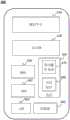
图4是根据本发明的一些实施例可以实现的移动设备400的示例性硬件和/或软件组件的示意图。在一些实施例中,所述MRI系统100的一个或多个组件可以在所述移动设备400的一个或多个组件上实现。仅作为示例,终端140可以在所述移动设备400的一个或多个组件上实现。FIG. 4 is a schematic diagram of exemplary hardware and/or software components of a
如图4所示,所述移动设备400可以包括通信平台410、显示器420、图形处理单元(GPU)430、中央处理单元(CPU)440、I/O 450、内存460和存储器490。在一些实施例中,所述移动设备400还可以包括但不限于系统总线或控制器(图中未示出)的任何其他合适组件。在一些实施例中,移动操作系统470(例如iOSTM、AndroidTM、Windows PhoneTM等)和一个或多个应用程序480可以从所述存储器490加载到所述内存460中,以便由所述CPU 440执行。所述应用程序480可以包括浏览器或任何其他合适的移动应用,用于接收和呈现与所述MRI系统100相关的信息。信息流的用户交互可以通过所述I/O 450来实现,并且经由所述网络150提供给所述处理设备120和/或所述MRI系统100的其他组件。As shown in FIG. 4 , the
为了实现本发明中描述的各种模块、单元及其功能,可以将计算机硬件平台用作此处描述的一个或多个元件的硬件平台。具有用户界面元素的计算机可用于实现个人计算机(PC)或其他类型的工作站或终端设备,经过适当编程,计算机也可充当服务器。To implement the various modules, units and functions described in the present invention, a computer hardware platform may be used as the hardware platform for one or more elements described herein. A computer with user interface elements can be used to implement a personal computer (PC) or other type of workstation or terminal device, and when properly programmed, the computer can also act as a server.
图5是根据本发明的一些实施例的示例性处理设备120的框图。如图5所示,所述处理设备120可以包括采集模块502和检测模块504。FIG. 5 is a block diagram of an
所述采集模块502可以用于获取与所述MRI系统100有关的信息。例如,所述采集模块502可以获取由MR扫描仪获取的受试者的扫描数据。可以指示所述MR扫描仪在所述受试者上施加MR脉冲序列,并检测由所述MR脉冲序列激发的多个回波信号。所述采集模块502可以从所述MR扫描仪和/或存储所述回波信号的存储设备中获取所述回波信号,以用于进一步分析。在一些实施例中,所述MR脉冲序列可以包括与图7所示的MR脉冲序列相同或相似的配置。例如,所述MR脉冲序列可以包括第一采集和第二采集。所述采集模块502可以采集在第一采集中检测到的第一回波信号和在第二采集中检测到的第二回波信号。关于所述MR脉冲序列,第一组回波信号和第二组回波信号的更多描述可以在本发明的其他位置找到。参见操作步骤601及其相关描述。The
所述检测模块504可以用于基于所述受试者的扫描数据对所述受试者执行检测。对所述受试者执行的检测可以包括确定所述受试者的物理点的定量参数,生成所述受试者的定量图(其包括所述受试者的每个物理点的定量参数值),生成反映所述受试者的生理特征的特定图像,和/或可以评估所述受试者的特征的任何其他度量。在一些实施例中,可以基于多维度融合(MDI)算法来执行检测。关于检测的更多描述可以在本发明的其他位置找到。参见操作步骤602和实施例1至4及其相关描述。The
在一些实施例中,所述模块可以是所述处理设备120的全部或一部分的硬件电路。所述模块还可以被实现为由所述处理设备120读取和执行的应用或指令集。此外,所述模块可以是硬件电路和应用程序/指令的任意组合。例如,当所述处理设备120正在执行应用/指令集时,所述模块可以是所述处理设备120的一部分。In some embodiments, the modules may be hardware circuits of all or part of the
应当注意,对所述处理设备120的上述描述仅仅是为了解释说明的目的,并不打算限制本发明的范围。对于本领域的普通技术人员来说,可以在本发明的教导下进行多种变化和修改。然而,那些变化和修改并不脱离本发明的范围。在一些实施例中,所述处理设备120还可以包括一个或多个附加模块,例如存储模块。另外可选择地,可以省略上述模块中的一个或多个模块。此外,以上提及的任何模块可以通过两个以上独立的单元来实现。例如,所述检测模块504可以被划分为多个子单元,每个子单元用于对所述受试者执行一个或多个特定检测。It should be noted that the above description of the
图6是根据本发明的一些实施例的用于对受试者执行检测的示例性过程的流程图。在一些实施例中,步骤600的一个或多个操作可以在图1所示的所述MRI系统100中实现。例如,所述步骤600可以以指令的形式存储在所述MRI系统100的存储设备(例如,所述存储设备130,所述存储器320和/或所述存储器490)中,并被调用,和/或由所述处理设备120(例如,如图3所示的所述计算设备300的处理器310,如图4所示的所述移动设备400的所述CPU440,如图5所示的一个或多个模块)执行。6 is a flowchart of an exemplary process for performing detection on a subject, according to some embodiments of the invention. In some embodiments, one or more operations of
在步骤601中,所述处理设备120(例如,所述采集模块502,所述处理器310的所述接口电路)可以获取与所述受试者相关的第一组回波信号和第二组回波信号。如此处所用的,所述受试者可以指任何生物性或非生物性的受试者,例如患者(或患者的一部分),人造物体(例如仿真体)。In
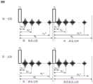
在一些实施例中,可以通过采用MR扫描仪(例如,所述MR扫描仪110)来获取所述第一组回波信号和所述第二组回波信号,以对所述受试者执行扫描。在扫描期间,所述MR扫描仪可以在所述受试者上施加MR脉冲序列。为了说明的目的,在图7中提供了示例性的MR脉冲序列700。如图7所示,所述MR脉冲序列700对应于第一采集和第二采集。在所述第一采集中可以激励所述第一组回波信号,并且在所述第二采集中可以激励所述第二组回波信号。所述第一采集和所述第二采集中的每一个可以包括多个重复过程。例如,所述第一采集可以至少包括第一重复过程和第二重复过程。所述第二采集可以至少包括第三重复过程和第四重复过程。所述第一,第二,第三和第四重复过程分别可以具有重复时间TR1、TR2、TR3和TR4。In some embodiments, the first set of echo signals and the second set of echo signals may be acquired by using an MR scanner (eg, the MR scanner 110 ) to perform the scanning. During scanning, the MR scanner may apply a sequence of MR pulses on the subject. An exemplary
单个采集中的重复过程可以具有相同的重复时间或不同的重复时间,即TR1可以等于或不同于TR2,TR3可以等于或不同于TR4。所述第一和第三重复过程可以具有相同的重复时间或不同的重复时间,即TR3可以等于或不同于TR1。所述第二和第四重复过程可以具有相同的重复时间或不同的重复时间,即TR4可以等于或不同于TR2。The repetitions in a single acquisition can have the same repetition time or different repetition times, ie TR1 can be equal to or different from TR2 and TR3 can be equal to or different from TR4. The first and third repetitions may have the same repetition time or different repetition times, ie TR3 may be equal to or different from TR1. The second and fourth repetitions may have the same repetition time or different repetition times, ie TR4 may be equal to or different from TR2.
所述MR脉冲序列700的采集中的每个重复过程可以包括具有特定翻转角的激励脉冲。在一些实施例中,同一采集中的不同重复过程的翻转角可以相同或不同。例如,如图7所示,在所述第一采集的所述第一和第二重复过程中的激励脉冲都具有翻转角α1。在所述第二次采集的所述第三和第四重复过程中的激励脉冲都具有翻转角α2。所述翻转角α2可以等于或不同于所述翻转角α1。在一些实施例中,所述翻转角α2可以不同于所述翻转角α1,以获取具有不同翻转角的数据集。在一些实施例中,步骤600可以被实施来实现对所述受试者的T1检测。T1检测的准确性会受到射频脉冲不均匀性(即射频脉冲场的空间分布不均匀)的影响。所述射频脉冲不均匀性可以导致在所述受试者的物理点处的实际翻转角和预设翻转角之间的差异(例如,α1或α2)。具有不同重复时间的数据集可用于确定所述物理点上的实际翻转角或所述受试者中的实际翻转角分布,从而提高T1检测的准确性。关于T1检测的更多描述可以在本发明的其他位置找到。参见实施例1及其相关描述。Each repetition in the acquisition of the
在一些实施例中,在所述第一采集和所述第二采集的至少一个重复过程期间,可以在多个回波时间中产生(或检测)多个回波信号。例如,在每个所述第一、第二、第三和第四重复过程期间,可以在多个回波时间中获取多个回波信号。如图7所示,在所述第一采集的所述第一重复过程的回波时间TE11、TE12...TE1N1顺序检测到N1个回波信号。在所述第一采集的所述第二重复过程的回波时间TE21、TE22、...TE2N2顺序检测到N2个回波信号。N1可以等于或不同于N2。例如,N1可以等于或小于N2。所述第一重复过程中的第i个(i是等于或小于N1的正整数)回波信号的回波时间可以与所述第二重复过程中前N1个回波信号的第i个回波信号的回波时间相同。即TE11=TE21,TE12=TE22,...,TE1N1=TE2N1。在另一实施例中,N1可以小于N2,并且所述第一重复过程中的第i个回波信号的回波时间可以不同于所述第二重复过程中前N1个回声信号的第i回波信号的回波时间,即TE11≠TE21,TE12≠TE22,...,TE1N1≠TE2N1。In some embodiments, during at least one repetition of said first acquisition and said second acquisition, a plurality of echo signals may be generated (or detected) in a plurality of echo times. For example, during each of said first, second, third and fourth repetitions a plurality of echo signals may be acquired in a plurality of echo times. As shown in FIG. 7 , N1 echo signals are sequentially detected at the echo times TE11 , TE12 . . . TE1N1 of the first repetition process of the first acquisition. N2 echo signals are sequentially detected at the echo times TE21 , TE22 , . . . TE2N2 of the second repetition process of the first acquisition. N1 may be equal to or different from N2 . For example, N1 may be equal to or smaller than N2 . The echo time of the i-th (i is a positive integer equal to or less thanN1 ) echo signal in the first repetition process may be the same as that of the i-th echo signal of the firstN1 echo signals in the second repetition process The echo times of the echo signals are the same. That is, TE11 =TE21 , TE12 =TE22 , . . . , TE1N1 =TE2N1 . In another embodiment, N1 may be smaller than N2 , and the echo time of the i-th echo signal in the first repetition process may be different from that of the first N1 echo signals in the second repetition process. The echo time of the i-th echo signal, that is, TE11 ≠TE21 , TE12 ≠TE22 , . . . , TE1N1 ≠TE2N1 .
类似地,在所述第二采集的所述第三重复过程的回波时间TE31、TE32...TE3N3顺序检测到N3个回波信号。在所述第二采集的所述第四重复过程的回波时间TE41、TE42、...TE4N4顺序检测到N4个回波信号。N3可以等于或不同于N4。所述第三重复过程中的第j个(j是等于或小于N3和N4的正整数)回波信号的回波时间可以与所述第四重复过程中第j个回波信号的回波时间相同或不同。Similarly, N3 echo signals are sequentially detected at echo times TE31 , TE32 . . . TE3N3 of the third repetition process of the second acquisition. N4 echo signals are sequentially detected at the echo times TE41 , TE42 , . . . TE4N4 of the fourth repetition process of the second acquisition. N3 may be equal to or different from N4 . The echo time of the jth (j is a positive integer equal to or less thanN3 andN4 ) echo signal in the third repetition process may be the same as the echo time of the jth echo signal in the fourth repetition process The wave times are the same or different.
N1,N2,N3和N4中的每一个可以是大于0的正整数。N1和N2的总和可以等于或不同于N3和N4的总和。所述第一重复过程的N1可以等于或不同于所述第三重复过程的N3。例如,N1可以小于或等于N3。所述第一重复过程中的第i个回波信号的回波时间可以与所述第三重复过程中前N1个回波信号的第i回波信号的回波时间相同或不同。类似地,所述第二重复过程的N2可以等于或不同于所述第四重复过程的N4。例如,N2可以小于或等于N4。所述第二重复过程中的第j个回波信号的回波时间可以与所述第四重复过程中前N2个回波信号中的第j个回波信号的回波时间相同或不同。Each of N1 , N2 , N3 and N4 may be a positive integer greater than 0. The sum ofN1 andN2 may be equal to or different from the sum ofN3 andN4 . N1 of the first iteration may be equal to or different from N3 of the third iteration. For example, N1 may be less than or equal to N3 . The echo time of the i-th echo signal in the first repetition process may be the same as or different from the echo time of the i-th echo signal of the first N1 echo signals in the third repetition process. Similarly,N2 of the second iteration may be equal to or different fromN4 of the fourth iteration. For example, N2 may be less than or equal to N4 . The echo time of the jth echo signal in the second repetition process may be the same as or different from the echo time of the jth echo signal in the firstN2 echo signals in the fourth repetition process.
在一些实施例中,所述第一采集和所述第二采集中的至少一个重复过程可以包括流动调制(FM)模块。流动调制模块的流动调制方式包括无流动调制、流动补偿、流动散相和流动编码中的至少一种,举例来说,FM模块可以包括流动补偿(FC)模块、流动散相(FD)模块、流动编码(FE)模块等。FM模块在MR扫描中会对体液(例如血液)产生影响,但对非流体组织(例如骨骼)则没有影响或影响很小。例如,在应用FC模块的重复过程中,在某个回波时间的体液的信号强度可以高于在应用FD模块的重复过程中的体液的信号强度。在另一实施例中,在应用正FE模块的重复过程中体液可以具有正相,在应用负FE模块的重复过程中体液可以具有负相。In some embodiments, at least one of the iterative process of the first acquisition and the second acquisition may comprise a flow modulation (FM) module. The flow modulation mode of the flow modulation module includes at least one of no-flow modulation, flow compensation, flow bulk and flow encoding. For example, the FM module can include a flow compensation (FC) module, a flow bulk (FD) module, Flow Encoding (FE) modules, etc. The FM module has an effect on bodily fluids (such as blood) in MR scans, but has little or no effect on non-fluid tissues (such as bone). For example, the signal intensity of the bodily fluid at a certain echo time may be higher during repetitions using the FC module than during repetitions using the FD module. In another embodiment, the bodily fluid may have a positive phase during repetitions using the positive FE module and may have a negative phase during repetitions using the negative FE module.
如图7所示,所述MR脉冲序列700中的每个重复过程可以包括FM模块。所述第一、第二、第三和第四重复中的FM模块分别表示为FM1、FM2、FM3和FM4。FM1、FM2、FM3和FM4可以是相同类型或不同类型。例如,FM1、FM2、FM3和FM4都可以是FC模块。在一些实施例中,FM1、FM2、FM3和FM4中的至少两个可以是不同类型的。例如,所述第一采集中的FM1和FM2可以是某种类型(例如,FC模块),而FM3和FM4可以是另一种类型(例如,FD模块)。作为另一个示例,FM1和FM3可以是某种类型的(例如,正FE模块),而FM2和FM4可以是另一种类型的(例如,负FM模块)。在一些实施例中,结合一个或多个FM模块的MR脉冲序列可以用于获取体液表现的特定特征图像,从而为磁共振血管造影(MRA)成像提供基础。关于MRA成像的更多描述可以在本发明的其他位置找到。参见实施例2及其相关描述。As shown in FIG. 7 , each repetition process in the
在一些实施例中,在执行所述第一和第二采集期间,所述MR脉冲序列700的一个或多个其他参数,例如VENC值,与梯度场有关的参数等,可以具有固定值。可选地,在施加所述MR脉冲序列700的过程中,可以利用一种以上成像技术来加快扫描进度,例如但不限于K空间采集技术、并行成像技术、压缩感测技术、K空间数据共享技术等。In some embodiments, one or more other parameters of the
应当注意,提供所述MR脉冲序列700仅仅是为了解释说明的目的,并不打算限制本发明的范围。在一些实施例中,所述MR脉冲序列700可以具有与图7所示的示例性配置不同的配置。例如,所述MR脉冲序列700可以具有两个以上的采集,例如3、4或5个采集。在另一实施例中,N1,N2,N3和N4中的一个或多个可以等于1,即,在所述第一、第二、第三和第四重复过程中的一个或多个仅可以获取一个回波信号。在另一实施例中,所述MR脉冲序列700的采集可以仅包括一个重复。另外可选地,所述MR脉冲序列700可以包括上述一个或多个附加组件,和/或,省略上述一个或多个组件(例如,FM1、FM2、FM3和FM4中的一个或多个)。It should be noted that the
在一些实施例中,可以根据实际需要来设计所述MR脉冲序列700的配置,如要对所述受试者执行的检测。例如,如果要执行T1检测,则翻转角α2可能需要与翻转角α1不同。在一些实施例中,翻转角α2可以不同于翻转角α1。在每个采集的每个重复过程中可以检测到多个回波信号。所述第二重复过程的TR2可以不同于所述第一重复过程的TR1,和/或所述第四重复过程的TR4可以不同于所述第三重复过程的TR3。FM1,FM2,FM3和FM4中的至少两个可以是不同类型的FM模块。如此,可以在所述受试者的扫描过程中获取更多与所述受试者有关的数据,包括对应于不同TE的数据、对应于不同翻转角的数据、对应于不同FM模块的数据、对应于不同TR的数据;从而在不延长扫描时间的情况下提高采集效率。实现基于单次扫描同时执行所述受试者的不同检测,从而避免了对所述受试者的不必要和重复的扫描。In some embodiments, the configuration of the
在一些实施例中,所述MR扫描仪可以包括多个线圈单元,每个线圈单元可以用于在所述受试者的扫描期间独立地检测回波信号。所述第一组回波信号和所述第二组回波信号可以包括由线圈单元之一检测到的回波信号。例如,所述第一组回波信号可以包括在所述第一采集中通过特定线圈单元检测到的回波信号,所述第二组回波信号可以包括在所述第二采集中通过所述特定线圈单元检测到的回波信号。可选地,所述第一组回波信号和所述第二组回波信号可以包括由两个以上线圈单元检测到的回波信号。例如,所述第一组回波信号可以包括在所述第一采集中通过每个线圈单元检测到的回波信号,所述第二组回波信号可以包括在所述第二采集中通过每个线圈单元检测到的回波信号。In some embodiments, the MR scanner may comprise a plurality of coil units, each coil unit may be used to independently detect echo signals during scanning of the subject. The first group of echo signals and the second group of echo signals may include an echo signal detected by one of the coil units. For example, the first set of echo signals may include echo signals detected by a specific coil unit in the first acquisition, and the second set of echo signals may include echo signals detected in the second acquisition by the Echo signal detected by a specific coil unit. Optionally, the first group of echo signals and the second group of echo signals may include echo signals detected by more than two coil units. For example, the first set of echo signals may include echo signals detected by each coil unit in the first acquisition, and the second set of echo signals may include echo signals detected by each coil unit in the second acquisition. The echo signal detected by each coil unit.
在步骤602中,所述处理设备120(例如,所述检测模块504,所述处理器310的处理电路)可以基于所述第一组回波信号或所述第二组回波信号中的至少一个对所述受试者执行检测。In
如此处所用的,“基于所述第一组回波信号或所述第二组回波信号中的至少一个”的过程(例如,检测过程)可以指基于所述第一组回波信号(或所述第一组回波信号的一部分)和/或所述第二组回波信号(或所述第二组回波信号的一部分)。对所述受试者执行的检测可以包括确定所述受试者的物理点的定量参数,生成所述受试者的定量图(其包括所述受试者的每个物理点的定量参数值),生成反映所述受试者的生理特性的特定图像,和/或可以评估所述受试者的特征的任何其他度量。物理点的示例性定量参数可以包括T1、T2、横向弛豫衰减(T2*)、信号衰减率(R2)、横向弛豫率(R2*)、B0场、射频脉冲场、实际翻转角、质子密度(PD)、含水量、含脂量等,或其组合。所述受试者的示例性定量图可以包括T1定量图、T2定量图、T2*定量图、R2定量图、R2*定量图、B0场分布图、射频脉冲场分布图、PD分布图、含水量分布图、含脂量分布图、磁敏感定量(QSM)图等,或其组合。所述受试者的示例性图像可以包括虚拟图像、MRA图像、磁化率加权图像(SWI)、T1加权图像、PD加权图像、T1加权增强图像、T2加权图像、T2*加权图像、水脂分离图像等,或其组合。As used herein, a process (eg, a detection process) based on "at least one of the first set of echo signals or the second set of echo signals" may refer to a process based on the first set of echo signals (or part of the first set of echo signals) and/or the second set of echo signals (or part of the second set of echo signals). The detection performed on the subject may comprise determining quantitative parameters of physical points of the subject, generating a quantitative map of the subject comprising quantitative parameter values for each physical point of the subject ), generate specific images reflecting physiological characteristics of the subject, and/or any other measure by which characteristics of the subject can be assessed. Exemplary quantitative parameters of a physical point may include T1, T2, transverse relaxation decay (T2*), signal decay rate (R2), transverse relaxation rate (R2*), Bo field, RF pulse field, actual flip angle, proton Density (PD), water content, fat content, etc., or a combination thereof. Exemplary quantitative maps of the subject may include T1 quantitative maps, T2 quantitative maps, T2* quantitative maps, R2 quantitative maps, R2* quantitative maps, B0 field distribution maps, radio frequency pulsed field distribution maps, PD distribution maps, containing Water distribution diagram, lipid content distribution diagram, quantitative susceptibility (QSM) diagram, etc., or a combination thereof. Exemplary images of the subject may include virtual images, MRA images, susceptibility-weighted images (SWI), T1-weighted images, PD-weighted images, T1-weighted enhanced images, T2-weighted images, T2*-weighted images, hydrolipid separation images, etc., or a combination thereof.
在一些实施例中,所述受试者的检测结果可以包括所述受试者的基本图像、初步图像或高级图像中的至少一个。如此处所用的,基本图像可以指基于所述第一组回波信号和/或所述第二组回波信号的一个或多个回波信号直接重建的图像。初步图像可以指基于一个或多个基本图像生成的图像。高级图像可以指基于一个或多个基本图像和一个或多个初步图像生成的图像。In some embodiments, the detection result of the subject may include at least one of a basic image, a preliminary image or an advanced image of the subject. As used herein, a base image may refer to an image directly reconstructed based on one or more echo signals of said first set of echo signals and/or said second set of echo signals. A preliminary image may refer to an image generated based on one or more basic images. A high-level image may refer to an image generated based on one or more base images and one or more preliminary images.
示例性基本图像可以包括T1加权图像、PD加权图像、T2加权图像、T2*加权图像、相位图像、亮血图像、黑血图像、相衬MRA图像等,或其组合。在一些实施例中,可以基于结合FC模块的MR脉冲序列生成亮血图像。可以基于结合FD模块的MR脉冲序列生成黑血图像。可以基于结合FE模块(例如,正FE模块或负FE模块)的MR脉冲序列生成相衬MRA图像。示例性初步图像可以包括T1定量图、T2定量图、T2*定量图、R2定量图、R2*定量图、B0场分布图、射频脉冲场分布图、PD分布图、水脂分离图像(例如,水图像,脂肪图像)、含水量分布图、含脂量分布图、QSM图、SWI图像、T1加权增强图像、MRA图像(例如相衬MRA图像、飞行时间(TOF)MRA图像)等,或其组合。示例性高级图像可以包括虚拟图像,如虚拟饱和度恢复图像(例如,虚拟饱和度恢复T1加权图像)、虚拟反转恢复(IR)图像(例如,虚拟IR T1加权图像、虚拟IR白质(WM)无效图像、虚拟IR灰质(GM)无效图像、虚拟IR脑脊液(CSF)无效图像)、虚拟双IR图像(例如,虚拟双IR WM图像、虚拟双IR GM图像、虚拟双IRCSF图像)、虚拟相敏反转恢复(PSIR)图像、虚拟稳态图像(例如,虚拟PD加权图像、虚拟T1加权图像、虚拟T2*加权图像)等,或其组合。Exemplary base images may include T1 weighted images, PD weighted images, T2 weighted images, T2* weighted images, phase images, bright blood images, dark blood images, phase contrast MRA images, etc., or combinations thereof. In some embodiments, bright blood images can be generated based on the MR pulse sequence in combination with the FC module. Black blood images can be generated based on MR pulse sequences combined with the FD module. Phase-contrast MRA images can be generated based on MR pulse sequences incorporating FE modules (eg, positive FE modules or negative FE modules). Exemplary preliminary images may include T1 quantitative maps, T2 quantitative maps, T2* quantitative maps, R2 quantitative maps, R2* quantitative maps, B0 field profiles, RF pulsed field profiles, PD profiles, water-fat separation images (e.g., water image, fat image), water content distribution map, fat content distribution map, QSM map, SWI image, T1-weighted enhanced image, MRA image (such as phase contrast MRA image, time-of-flight (TOF) MRA image), etc., or combination. Exemplary advanced images may include virtual images such as virtual saturation restored images (e.g., virtual saturation restored T1-weighted images), virtual inversion restoration (IR) images (e.g., virtual IR T1-weighted images, virtual IR white matter (WM) Null images, virtual IR gray matter (GM) null images, virtual IR cerebrospinal fluid (CSF) null images), virtual dual IR images (e.g., virtual dual IR WM images, virtual dual IR GM images, virtual dual IRCSF images), virtual phase sensitive Inversion recovery (PSIR) images, virtual steady-state images (eg, virtual PD-weighted images, virtual T1-weighted images, virtual T2*-weighted images), etc., or combinations thereof.
为了说明的目的,此处采用与特定定量参数有关的检测信号来共同地确定物理点的特定定量参数的值,和/或生成与该特定定量参数有关的定量图或图像。例如,可以采用对应不同翻转角所检测得到的信号来共同地确定物理点的T1值,生成所述受试者的T1定量图、T1加权图像、T1加权增强图像等,或其组合。For purposes of illustration, detection signals associated with a particular quantitative parameter are employed herein to collectively determine the value of a particular quantitative parameter of a physical point and/or generate a quantitative map or image associated with that particular quantitative parameter. For example, the detected signals corresponding to different flip angles can be used to jointly determine the T1 value of the physical point, and generate the subject's T1 quantitative map, T1 weighted image, T1 weighted enhanced image, etc., or a combination thereof.
在一些实施例中,所述处理设备120可以通过执行以下描述的示例公开的方法来对所述受试者执行检测。在一些实施例中,所述处理设备120可以基于多维度融合(MDI)算法对所述受试者执行测量。所述MDI算法可以在所述检测中集成不同信号维度的数据。例如,所述检测可以涉及所述受试者的物理点的参数。所述处理设备120可以基于所述第一组和/或第二组回波信号来确定所述物理点的信号表征,并且可以基于所述物理点的信号表征来确定检测。信号表征可以与所述参数相关联。如此处所用的,信号表征可以指所述第一组(或所述第一组的一部分)和/或所述第二组(或所述第二组的一部分)中的回波信号的代表值或属性值。所述受试者的信号表征可以反映所述受试者的一种以上生理特征或物理特征,这可以为医学诊断和/或治疗提供基础。In some embodiments, the
在一些实施例中,所述处理设备120可以基于所述第一组和/或所述第二组回波信号来确定所述物理点的多个信号。此时,所述物理点的信号可以传达关于所述物理点的一个或多个属性或特性的信息。例如,所述物理点的信号可以包括与所述物理点有关的图像数据或K空间数据。在一些实施例中,所述处理设备120可以重建多个图像。可以基于所述第一组或所述第二组回波信号来重建每个图像,并且每个图像包括所述物理点的图像数据(例如,具有特定像素值的像素,具有特定体素值的体素)。然后,所述处理设备120可以将所述图像中的所述物理点的所述图像数据指定为所述物理点的信号。所述物理点的每个信号可以对应于采用MR扫描仪采集信号的多个信号维度中的一组值。信号的信号维度可以为实施例中描述的参数,比如如图2所述的,采用MR扫描仪来确定或获取信号。举例来说,信号维度可以包括TE、TR、线圈单元、重复过程、翻转角、采集等,或其组合。In some embodiments, the
所述处理设备120还可以确定所述多个信号维度中的主信号维度和至少一个辅信号维度。主信号维度可以指与信号表征相关联的信号的信号维度。如果所述信号维度和所述信号表征具有一定的数学相关性(例如,指数相关性、线性相关性或任何其他数学相关性),则可以认为所述信号维度与所述信号表征相关联。所述至少一个辅信号维度可以包括除主信号维度以外的信号的任何信号维度。所述至少一个辅信号维度可以包括除主信号维度以外的任何信号维度。在一些实施例中,每个辅信号维度可以不与信号表示相关联。在一些实施例中,所述至少一个辅信号维度可以包括除主信号维度以外的信号的全部或部分信号维度。The
所述处理设备120还可以基于多个信号,所述主信号维度和所述至少一个辅信号维度来确定物理点的信号的数值表征。例如,对于所述至少一个辅信号维度中的至少一个值,所述处理设备120可以基于对应于所述至少一个辅信号维度的值的多个信号的一部分,来确定与所述主信号维度相关联的所述物理点的至少一个初步信号表征,并基于所述受试者的所述至少一个初步信号表征的至少一部分来确定所述受试者的所述信号表示。在另一实施例中,所述处理设备120可以通过将所述多个信号输入到信号表征的优化函数中来确定所述物理点的信号的数值表征,该优化函数结合了所述主信号维度和所述至少一个辅信号维度。有关MDI算法的更多描述可以在如2019年3月18日提交的美国申请(申请为16/357,313,发明名称为“磁共振成像中确定信号表征的系统和方法”)中找到,在此引用其全部内容。The
应当注意,关于步骤600的上述描述仅仅出于说明的目的,并不打算限制本发明的范围。对于本领域技术人员而言,可以在本发明的教导下进行多种变化和修改。然而,那些变化和修改不脱离本发明的范围。在一些实施例中,步骤600可以利用一个或多个未描述的附加操作和/或不具有上述讨论的一个或多个操作来完成。例如,步骤600可以包括将检测结果发送到终端设备(例如,医生的设备终端140)以进行显示的附加操作。It should be noted that the above description about
提供以下实施例是出于说明的目的,而并非旨在限制本发明的范围。The following examples are provided for the purpose of illustration and are not intended to limit the scope of the invention.
实施例1Example 1
图8是根据本发明的一些实施例的示例性MR脉冲序列800的示意图。所述MR脉冲序列800可以是如上所述的MR脉冲序列700的示例性实施例。FIG. 8 is a schematic diagram of an exemplary
如图8所示,所述MR脉冲序列800包括第一采集和第二采集。所述第一采集包括第一重复过程和第二重复过程,在每次重复过程期间应用具有翻转角α1的激励脉冲。所述第二采集包括第三重复过程和第四重复过程,在每次重复过程期间应用具有翻转角α2的激励脉冲。所述翻转角α2可不同于所述翻转角α1。所述第一重复过程和所述第三重复过程的重复时间均等于TR1,所述第二重复过程和所述第四重复过程的重复时间均等于TR2。TR2可多于TR1。在所述第一重复过程和所述第三重复过程的每次重复期间,在回波时间分别为TE11、TE12...TE1N1时采集N1回波信号,在所述第二重复过程和所述第四重复过程的每次重复期间,在回波时间分别为TE21、TE22、...TE2N2时采集N2回波信号。N2可以大于N1。TE11、TE12...TE1N1可以分别与TE21、TE22、...TE2N2相等。As shown in FIG. 8, the
在一些实施例中,MR扫描仪(例如MR扫描仪110)可被指示对受试者施加所述MR脉冲序列800,以在第一采集中获取第一组回波信号,在第二采集中获取第二组回波信号。所述第一组回波信号和所述第二组回波信号都可以包括(N1+N2)*NC个回波信号,其中NC可以是指所述MR扫描仪的线圈单元的数量,所述MR扫描仪的线圈单元用于获取要进行本发明所述的进一步处理的回波信号。NC可以是任何等于或小于所述MR扫描仪的线圈单元的总数。为了说明的目的,假设NC等于1,并且所述第一组回波信号和所述第二组回波信号都包括由所述MR扫描仪的特定线圈单元检测到的(N1+N2)个回波信号。In some embodiments, an MR scanner (eg, MR scanner 110) may be instructed to apply the
所述处理设备120可以基于所述第一组回波信号和所述第二组回波信号中的每个回波信号重构图像,从而生成2×(N1+N2)个图像。在一些实施例中,每个重建图像可以包括多个像素,每个像素具有像素值。重建图像中像素的像素值可以是包括相位分量和振幅分量的实数值或复数值。为了便于描述,与所述第一重复过程相对应的N1图像、与所述第二重复过程相对应的N2图像、与所述第三重复过程相对应的N1图像和与所述第四重复过程相对应的N2图像分别被称为第一图像集、第二图像集、第三图像集和第四图像集。


式中,M0(r)是指Pr的PD,


在一些实施例中,所述处理设备120可以对所述受试者执行T2检测和/或R2检测,例如,可以确定Pr处的T2值(记为T2(r))和/或Pr处的T2*值(记为


为了举例说明,提供


作为又一示例,所述处理设备120可以基于MDI算法来确定

在一些实施例中,所述处理设备120可以对所述受试者执行B0场检测。例如,可以确定Pr处的局部场分布ΔB0(r),和/或生成所述受试者的ΔB分布图。以ΔB0(r)为例,可以用类似于
可选地,所述处理设备120还可以基于B0场检测的结果,执行与所述受试者的组织磁化率有关的检测。例如,所述处理设备120可以确定Pr的磁敏感定量图像(QSM)参数(例如,局部磁化率场、背景磁化率场、在先信息和/或与局部磁化率场相关的伪影信息),和/或基于所述受试者的ΔB0(r)和/或ΔB0分布图生成所述受试者的磁敏感定量图像。在一些实施例中,可根据QSM算法执行与组织磁化率有关的检测。典型的QSM算法可以包括敏感定量和残差成像(QUASAR)算法、基于贝叶斯统计的优化算法。有关QSM算法的更多说明,可参见,例如于2019年1月14日提交的美国申请(申请号为16/247,098,发明名称为“确定磁化率分布的方法和系统”),以及于2018年12月28日提交的美国申请(申请号为16/235,117,发明名称为“衰减校正系统和方法”),其全部内容一并引用。Optionally, the
在一些实施例中,所述处理设备120可以执行关于受试者的实际翻转角(AFA)的检测。例如,可以确定在Pr处确定AFA,和/或生成所述受试者的AFA分布图。在某些情况下,射频脉冲的不均匀性可能导致Pr处的AFA和Pr处的预设翻转角度之间的差异,这会进一步影响T1定量图像的精度。因此,有必要为AFA的测定提供一种有效的方法。In some embodiments, the
为了举例说明,提供了在所述第一采集中的Pr处确定AFA的示例,其记为α’1(r)。在一些实施例中,所述处理设备120可以基于


可根据与所述第一重复过程中的第i个回波信号相对应的图像中Pr处的图像数据来确定


可将TR2与TR1的比记为n,从而可根据式(6)对式(3)进行如下变换:The ratio of TR2 and TR1 can be recorded as n, so that formula (3) can be transformed as follows according to formula (6):

然后,可根据式(7)确定α’1(r),如下所示:Then, α'1 (r) can be determined according to formula (7), as follows:

在所述第二采集中的Pr处的AFA的测定(记为α’2(r))可以用类似于α’1(r)的方式,基于

在一些实施例中,所述处理设备120可以基于所述MDI算法来确定Pr处的α’1(r)。仅作为一个示例,所述处理设备120可以基于Pr处的多个信号、与R(r)相关联的主信号维度(如,实际翻转角),和/或除所述主信号维度以外的至少一个辅信号维度(例如所述TE、所述线圈单元、所述采集、所述TR)来确定R(r),R(r)可以被视为如等式(7)中所示的与α’1(r)相关联的第二信号表征。例如,R(r)可以根据优化函数(8)确定,如下所示:In some embodiments, the

其中,Nacq是指MR脉冲序列800(即,在图8所示示例中的2个)的采集的总计数。所述处理设备120可以通过求解所述优化函数(8)来确定R(r),并且基于R(r)和等式(7)进一步确定α’1(r)。where Nacq refers to the total count of acquisitions of MR pulse sequences 800 (ie, 2 in the example shown in FIG. 8 ). The
在一些实施例中,可以确定α’1(r)与α1的比值来检测MR扫描仪的系统误差,例如,比值与1的差越大,系统误差越大。另外可选地,所述处理设备120还可以基于与AFA有关的检测结果对所述受试者执行射频脉冲传输场检测。例如,所述处理设备120可以基于实际翻转角度和射频脉冲传输场之间的线性相关来确定Pr处的射频脉冲传输场(记为B1(r))和/或生成所述受试者的射频脉冲传输场分布图。In some embodiments, the ratio of α'1 (r) to α1 may be determined to detect systematic errors of the MR scanner, for example, the greater the difference between the ratio and 1, the greater the systematic error. Optionally, the
在一些实施例中,所述处理设备120可以对所述受试者执行T1检测。例如,可以确定Pr处的T1值(记为T1(r))。另外可选地,可以生成所述受试者的T1定量图和/或T1加权图像。在一些实施例中,所述处理设备120可以基于所述第一组回波信号和/或所述第二组回波信号来确定与所述受试者相关的AFA或射频脉冲传输场中的至少一个。所述处理设备120还可以基于所述第一组回波信号、所述第二组回波信号和所述与所述受试者相关的AFA或射频脉冲传输场中的至少一个执行T1检测。In some embodiments, the
以T1(r)为例,所述处理设备120可以基于如上所述的第一组回波信号和/或第二组回波信号来确定α’1(r)和α’2(r)。所述处理设备120可以基于所述第一组回波信号、所述第二组回波信号、以及α’1(r)和α’2(r)来确定T1(r)。例如,可以基于


可将TR1与T1(r)的比值记为K,并可根据式(10)并基于式(4)和式(5)对式(9)进行变换,如下所示:The ratio of TR1 to T1 (r) can be recorded as K, and formula (9) can be transformed according to formula (10) and based on formula (4) and formula (5), as follows:

可以基于


aK2+bK+c=0, (11)aK2 +bK+c=0, (11)
其中,a、b和c可根据等式(12)-(14)确定,如下所示:where a, b and c can be determined according to equations (12)-(14) as follows:
a=n(n+1)cosα′1(r)cosα′2(r)(R′(r)cosα′1(r)-cosα′2(r)), (12)a=n(n+1)cosα′1 (r)cosα′2 (r)(R′(r)cosα′1 (r)-cosα′2 (r)), (12)
b=(n+1)(ncos2α′2(r)-nR′(r)cos2α′1(r)+cosα′1(r)cos2α′2(r)-R′(r)cos2α′1(r)cosα′2(r))+n(R′(r)sin2α′1(r)cosα′2(r)-cosα′1(r)sin2α′2(r)), (13)b=(n+1)(ncos2 α′2 (r)-nR′(r)cos2 α′1 (r)+cosα′1 (r)cos2 α′2 (r)-R′(r )cos2 α′1 (r)cos α′2 (r))+n(R′(r)sin2 α′1 (r)cos α′2 (r)-cos α′1 (r)sin2 α′2 (r)), (13)
c=sin2α′2(r)(n+cosα′1(r))-R′(r)sin2α′1(r)(n+cosα′2(r)), (14)c=sin2 α′2 (r)(n+cosα′1 (r))-R′(r)sin2 α′1 (r)(n+cosα′2 (r)), (14)
可以分别根据等式(15)和(16)确定K和T1(r)的值,如下所示:The values of K and T1 (r) can be determined according to equations (15) and (16), respectively, as follows:


在一些实施例中,K可以等于

在另一实施例中,可以基于


a′K2+b′K+c′=0. (17)a'K2 +b'K+c'=0. (17)
其中,a′、b′和c′可根据等式(18)-(20)确定,如下所示:where a', b' and c' can be determined according to equations (18)-(20) as follows:
a′=n(n+1)cosα′1(r)cos′2(r)(R′(r)cosα′1(r)-cosα′2(r)), (18)a′=n(n+1)cosα′1 (r)cos′2 (r)(R′(r)cosα′1 (r)-cosα′2 (r)), (18)
b′=(n+1)(cos2α′2(r)-R′(r)cos2α′1(r)+ncosα′1(r)cos2α′2(r)-nR′(r)cos2α′1(r)cosα′2(r))-n(R′(r)sin2α′1(r)cosα′2(r)-cosα′1(r)sin2α′2(r)), (19)b′=(n+1)(cos2 α′2 (r)-R′(r)cos2 α′1 (r)+ncosα′1 (r)cos2 α′2 (r)-nR′( r)cos2 α′1 (r)cos α′2 (r))-n(R′(r)sin2 α′1 (r)cos α′2 (r)-cos α′1 (r)sin2 α′2 (r)), (19)
c′=-sin2α′2(r)(1+ncosα′1(r))+R′(r)sin2α′1(r)(1+ncosα′2(r)), (20)c′=-sin2 α′2 (r)(1+ncosα′1 (r))+R′(r)sin2 α′1 (r)(1+ncosα′2 (r)), (20)
可以分别根据等式(21)确定T1(r)的值,如下所示:The value of T1 (r) can be determined according to equation (21), respectively, as follows:

在一些实施例中,T1(r)可以等于
理论上,根据等式(16)确定的T1(r)的值可以等于或基本等于根据式(21)确定的T1(r)的值。所述处理设备120可根据等式(16)或(21)确定T1(r)的值。或者,所述处理设备120可以分别根据等式(16)和(21)确定T1(r)的两个值,并且进一步确定所述两个值的平均值作为T1(r)的最终值。Theoretically, the value of T1 (r) determined according to equation (16) may be equal or substantially equal to the value of T1 (r) determined according to equation (21). The
在一些实施例中,所述处理设备120可以基于MDI算法来确定T1(r)。仅作为示例,所述处理设备120可基于Pr处的多个信号、与R′(r)相关联的主信号维度(即翻转角)、和/或除所述主信号维度之外的至少一个辅信号维度(例如所述TE、所述线圈单元、所述采集、所述TR)来确定R′(r)。在一些实施例中,R′(r)可根据如下的优化函数(22)确定:In some embodiments, the

所述处理设备120可以通过求解所述优化函数(22)来确定R′(r),并且基于R′(r)和方程(11)-(21)中的一个或多个来进一步确定T1(r)。The
在一些实施例中,所述处理设备120可以对所述受试者执行PD检测。例如,可以确定在Pr处的PD值(记为M0(r)),和/或生成所述受试者的PD分布图。为了说明的目的,作为示例描述M0(r)的确定。M0(r)可通过根据等式(23)转换等式(1)或根据等式(24)转换等式(2)确定,如下所示:In some embodiments, the


其中,m可以等于1或2.where m can be equal to 1 or 2.
理论上,根据等式(23)确定的M0(r)的值可以等于或基本上等于根据等式(24)确定的M0(r)的值。所述处理设备120可将所确定的K(即,TR1/T1(r))和
在一些实施例中,所述处理设备120可以对所述受试者执行含水检测和/或含脂检测。例如,在Pr处测定含水量和/或含脂量。另外可选地,可以生成所述受试者的水脂分离图像,例如水图像(也称为脂肪抑制图像)和/或脂肪图像。In some embodiments, the
为了说明的目的,作为示例描述所述水脂分离图像的生成。在一些实施例中,所述处理设备120可以在一次重复过程中获得的回波信号上生成所述水脂分离图像。或者,所述处理设备120可以生成多个水脂分离图像,每个水脂分离图像基于一次重复过程的回波信号生成。所述处理设备120可以将多个水脂分离图像的平均图像确定为最终水脂分离图像。For the purpose of illustration, the generation of the water-fat separation image is described as an example. In some embodiments, the
在一些实施例中,所述处理设备120可以根据水脂成像算法生成水脂分离图像,例如Dixon算法、具有回声不对称和最小二乘估计(理想)的水和脂肪的迭代分解算法、Flex算法、多点Dixon(mDixon)算法、FatSep算法、水-脂肪反相(WFOP)算法等,或其组合。例如,可以基于根据Dixon算法在所述第一重复过程中获得的回波信号生成所述水脂分离图像。所述第一重复过程中的激励脉冲可以在特定的TE激发回波信号,以实现与水和/或脂肪有关的检测。具有特定TE的回波信号可以包括第一TE处的第一回波信号(水和脂肪信号同相)和第二TE处的第二回波信号(水和脂肪信号180°异相)。所述处理设备120可以基于所述第一回波信号生成水和脂肪信号同相的图像I1,以及基于所述第二回波信号生成水和脂肪信号180°异相的图像I2。所述处理设备120可进一步确定0.5*(I1+I2)为水图像,和/或0.5*(I1-I2)为脂肪图像。在一些实施例中,可以基于MDI算法来执行水检测和/或脂肪检测。In some embodiments, the
在一些实施例中,所述处理设备120可以执行与所述受试者的一个或多个虚拟图像相关的检测。所述受试者的每个虚拟图像可以对应于特定MR脉冲序列,并且参考从对所述受试者执行的一个或多个其他检测的结果导出的图像,而不实际对所述受试者应用特定MR脉冲序列。例如,第一虚拟图像可对应于具有虚拟翻转角vα、虚拟回波时间vTE和虚拟重复时间vTR的GRE脉冲序列。可根据如下等式(25)确定所述第一虚拟图像中记为vS1(r)的Pr处的像素值:In some embodiments, the

其中,M0(r)和

在另一实施例中,第二虚拟图像可对应于具有虚拟回波时间vTE和虚拟反转时间vTI的IR脉冲序列。可根据如下等式(26)确定所述第二虚拟图像中记为vS2(r)的Pr处的像素值:In another embodiment, the second virtual image may correspond to an IR pulse sequence with a virtual echo time vTE and a virtual inversion time vTI. The pixel value at the Pr place denoted as vS2(r) in the second virtual image can be determined according to the following equation (26):

在另一实施例中,第三虚拟图像可对应于具有虚拟回波时间vTE和虚拟反转时间vTI的饱和恢复脉冲序列。可根据如下等式(27)确定所述第三虚拟图像中记为vS3(r)的Pr处的像素值:In another embodiment, the third virtual image may correspond to a saturation recovery pulse sequence with a virtual echo time vTE and a virtual inversion time vTI. The pixel value at the Pr place denoted as vS3(r) in the third virtual image can be determined according to the following equation (27):

在另一实施例中,第四虚拟图像可对应于具有虚拟回波时间vTE和虚拟反转时间vTI的相敏反转恢复脉冲序列。可根据如下等式(28)确定所述第四虚拟图像中记为vS4(r)的Pr处的像素值:In another embodiment, the fourth virtual image may correspond to a phase-sensitive inversion recovery pulse sequence with a virtual echo time vTE and a virtual inversion time vTI. The pixel value at the Pr place denoted as vS4(r) in the fourth virtual image can be determined according to the following equation (28):

其中,sign表示提取实数符号的数学函数。where sign represents a mathematical function that extracts the sign of a real number.
在另一实施例中,第五虚拟图像可对应于具有虚拟翻转角vα、虚拟回波时间vTE、虚拟反转时间vTI和虚拟重复时间vTR的稳态脉冲序列。可根据如下等式(29)确定所述第五虚拟图像中记为vS5(r)的Pr处的像素值:In another embodiment, the fifth virtual image may correspond to a steady state pulse sequence with a virtual flip angle vα, a virtual echo time vTE, a virtual inversion time vTI and a virtual repetition time vTR. The pixel value at the Pr place denoted as vS5(r) in the fifth virtual image can be determined according to the following equation (29):

在一些实施例中,所述处理设备120可以生成与上述GRE脉冲序列的vTE相对应的所述受试者的虚拟相位图。例如,所述虚拟相位图中Pr处的虚拟相位(记为为

可选地,所述处理设备120可以基于所述虚拟相位图和在一次以上重复过程中获得的回波信号进一步生成所述受试者的磁化率加权成像(SWI)图像。例如,相位掩模可以基于虚拟相位图,并且可以基于在一次以上重复过程中获得的回波信号生成所述受试者的幅度图像。可以基于所述相位图和所述幅度图生成所述受试者的SWI图像。在一些实施例中,所述SWI图像可以根据SWI算法生成,例如敏感度加权血管造影(SWAN)算法、SWI相位(SWIp)算法、血液敏感成像(BSI)算法、血流敏感黑血(FSBB)算法等。有关SWI技术的更多说明,可在如2017年5月13日提交美国申请(公开号为2018/0017652A1)和2016年7月14日提交的美国申请(公开号为2018/0231631A1)中找到,其发明名称均为“磁共振成像系统和方法”,其全部内容在此一并引用。Optionally, the
在一些实施例中,所述处理设备120可以进一步生成所述受试者的T1加权增强图像。例如,所述处理设备120可以根据由特定线圈单元检测到的第一重复过程中第i次回波信号生成所述受试者的T1加权增强图像。假设α2大于α1,则可根据如下等式(30)确定所述T1加权增强图像中Pr处的像素值:In some embodiments, the

其中,SaT1W(r)是指在所述T1加权增强图像中Pr处的像素值。Wherein, SaT1W (r) refers to the pixel value at Pr in the T1 weighted enhanced image.
在一些实施例中,可以基于根据MDI算法中如下所示的优化函数(31)来确定SaT1W(r):In some embodiments, SaT1W (r) may be determined based on the optimization function (31) as follows in the MDI algorithm:

在另一实施例中,所述处理设备120可以生成与每个线圈单元检测到的每次重复过程中的每个回波信号相对应的T1加权增强图像。所述处理设备120可以进一步生成T1加权增强图像的平均图像,作为与整个扫描相对应的所述受试者的T1加权增强图像。作为又一示例,所述处理设备120可以根据MDI算法生成与整个扫描相对应的所述受试者的T1加权增强图像。例如,所述处理设备120可以基于Pr处的多个信号、与SaT1W(r)相关联的主信号维度(即,翻转角)和/或除所述主信号维度以外的至少一个辅信号维度(例如,所述TE、所述线圈单元、所述采集、所述TR)确定SaT1W(r),其可被视为与所述翻转角相关联的第四信号表征。In another embodiment, the
实施例2Example 2
图9是根据本发明的一些实施例的示例性MR脉冲序列900的示意图。所述MR脉冲序列900可以是如上所述的MR脉冲序列700的示例性实施例。FIG. 9 is a schematic diagram of an exemplary
所述MR脉冲序列900可以具有与所述MR脉冲序列800相似的结构,除了某些组件或特征之外。如图9所示,所述第一采集和所述第二采集中的每个重复过程的激发脉冲的翻转角都可以等于α。所述第一重复过程和所述第三重复过程中的每一个可以包括FM模块FM1。所述第二重复过程和所述第四重复过程中的每一个可以包括与FM1不同的FM模块FM2。例如,FM1可以是FC模块,FM2可以是FD模块。在所述第一重复过程(或所述第三重复过程)的某一回波时间的体液信号强度会高于所述第二重复过程(或所述第四重复过程)的某一回波时间的体液信号信号强度。在另一实施例中,FM1可以是正FE模块,FM2可以是负FE模块。所述第一重复过程和所述第三重复过程的体液可以为正相位,所述第二重复过程和所述第四重复过程的体液可以为负相位。The
与所述MR脉冲序列800类似,所述MR脉冲序列900可应用于受试者以获取第一采集中的第一组回波信号和第二采集中的第二组回波信号。为了说明的目的,假设所述第一组回波信号和所述第二组回波信号都包括由所述MR扫描仪的特定线圈单元获取的(N1+N2)个回波信号。在一些实施例中,所述处理设备120基于所述第一组回波信号或所述第二组回波信号中的至少一个来执行与所述受试者的MR血管造影(MRA)图像有关的检测。例如,所述处理设备120可以基于所述第一组回波信号和/或所述第二组回波信号中的回波信号集合的第一部分生成所述受试者的至少一个第一图像。所述回波信号集合的第一部分可以包括在所述第一重复过程和/或所述第三重复过程中获取的一个或多个回波信号。所述处理设备120可以基于第一组回波信号和/或所述第二组回波信号中的回波信号集合的第二部分生成所述受试者的至少一个第二图像。所述回波信号集合的第二部分可以包括在第二重复过程和/或第四重复过程中获取的一个或多个回波信号。所述处理设备120可以基于所述至少一个第一图像和所述至少一个第二图像生成所述受试者的一个或多个MRA图像。Similar to the
为了说明的目的,假设所述至少一个第一图像包括2N1个图像,并且所述至少一个第二图像包括2N2个图像。所述2N1个图像包括与所述第一重复过程相对应的N1个图像(记为


所述处理设备120可以基于与特定TE相对应的所述第一图像和所述第二图像生成与所述特定TE相对应的MRA图像。仅作为示例,可以通过采用例如可以减去静态组织的减法技术(例如,线性减法技术或非线性减法技术),基于Ii和I′i(或I2i和I′2i)生成对应于
在一些实施例中,所述处理设备120可以基于所述第一组回波信号和/或所述第二组回波信号对所述受试者执行一个或多个其他检测。例如,与T2、T2*、R2、R2*、B0场、射频脉冲场、实际翻转角、水、脂肪、QSM等或其组合有关的检测可以采用与实施例1中描述的类似方式在所述受试者上执行。但是,与T1和PD相关的测量可能无法执行,因为根据实施例1中的相关描述,可能需要基于对应于不同翻转角的回波信号来执行与T1和PD相关的检测。In some embodiments, the
实施例3Example 3
图10是根据本发明的一些实施例的示例性MR脉冲序列1000的示意图。所述MR脉冲序列1000可以是如上所述的MR脉冲序列700的示例性实施例。Figure 10 is a schematic diagram of an exemplary
所述MR脉冲序列1000可以具有与所述MR脉冲序列900相似的结构,除了某些成分或特征外。如图10所示,所述第一采集中的所述第一重复过程和所述第二重复过程的激发脉冲都可以具有翻转角α1,并且所述第二采集中的所述第三重复过程和所述第四重复过程的激发脉冲都可以具有与α1不同的翻转角α2。The
在一些实施例中,所述MR脉冲序列1000可应用于受试者,以获取第一采集中的第一组回波信号和第二采集中的第二组回波信号。所述处理设备120可基于所述第一组回波信号和/或所述第二组回波信号,以与实施例1中所述的类似方式,执行与T2、T2*、R2、R2*、B0场、射频脉冲场、实际翻转角、T1、PD、水、脂肪、QSM等中的一个或多个有关的检测。另外可选地,所述处理设备120以与实施例2中描述的类似方式对所述受试者执行与MRA图像有关的检测。In some embodiments, the
实施例4Example 4
图11是根据本发明的一些实施例的示例性MR脉冲序列1100的示意图。所述MR脉冲序列1100可以是如上所述的MR脉冲序列700的示例性实施例。FIG. 11 is a schematic diagram of an exemplary
所述MR脉冲序列1100包括第一采集和第二采集。所述MR脉冲序列1100的第一采集具有与所述MR脉冲序列800的第一采集相同的配置。所述MR脉冲序列1100的第二采集具有与所述MR脉冲序列800的第二采集相似的配置,除了某些组件或特征之外。如图11所示,所述MR脉冲序列1100的第二采集包括第三重复过程和第四重复过程。在所述第三重复过程中,N1个回波信号在回波时间TE31、TE32...TE3N3依次获取。


在一些实施例中,所述MR脉冲序列1100可应用于受试者,以获取第一采集中的第一组回波信号和第二采集中的第二组回波信号。所述处理设备120可以通过与实施例1中描述的类似方式,对所述受试者执行与T2、T2*、R2、R2*、B0场、射频脉冲场、实际翻转角、T1、PD、水、脂肪、QSM等中的一个或多个有关的检测。另外可选地,所述处理设备120以与实施例2中描述的类似方式对所述受试者执行与MRA图像有关的检测。In some embodiments, the
在一些实施例中,与所述MR脉冲序列800相比,在所述第一重复过程和所述第三重复过程中使用不同的TE以及在所述第二重复过程和第四重复过程中使用不同的TE的MR脉冲序列1100可以为与水和/或脂肪有关的检测提供更合适的数据。例如,如结合实施例1所述,可激发特定TE处的回波信号以实现与水和/或脂肪有关的检测。具有特定TE的回波信号可以包括第一TE处的第一回波信号(水和脂肪信号同相)和第二TE处的第二回波信号(水和脂肪信号180°异相)。第一TE和第二TE之间的时差可能很短(例如,短于一个时间段),使得在一次信号采集中难以获取所述第一回波信号和所述第二回波信号。所述MR脉冲序列1100可用于在一次采集中在第一TE处获取所述第一回波信号,在另一次采集中在第二TE处获取所述第二回波信号,从而实现与水和/或脂肪有关的检测。In some embodiments, a different TE is used during the first and third iterations and a different TE is used during the second and fourth iterations compared to the
应当注意的是,如图7至图11所示的上述示例及其描述仅为说明的目的,并不旨在限制本发明的范围。对于本领域技术人员而言,可以在本发明的教导下进行多种变化和修改。然而,那些变化和修改不脱离本发明的范围。在一些实施例中,MR脉冲序列(700到1100中的任意一个)包括一个或多个附加组件和/或上述MR脉冲序列的一个或多个组件可以省略。此外,本发明提供的等式和优化函数是示例,并且可以以各种方式进行修改。例如,等式或优化函数可以包括一个或多个其他参数,和/或可以省略上面所示的一个或多个参数或者用其他参数替换。在一些实施例中,信号表征的优化函数可以包括一个或多个其他第二信号维度。It should be noted that the above examples shown in FIGS. 7 to 11 and their descriptions are for illustrative purposes only, and are not intended to limit the scope of the present invention. For those skilled in the art, various changes and modifications can be made under the teaching of the present invention. However, those changes and modifications do not depart from the scope of the present invention. In some embodiments, the MR pulse sequence (any of 700 to 1100 ) includes one or more additional components and/or one or more components of the MR pulse sequence described above may be omitted. In addition, the equations and optimization functions provided by the present invention are examples and can be modified in various ways. For example, an equation or optimization function may include one or more other parameters, and/or one or more parameters shown above may be omitted or replaced with other parameters. In some embodiments, the optimization function for signal characterization may include one or more other second signal dimensions.
图12A至图41C是根据本发明的一些实施例的患者大脑的示例性检测结果。所述检测结果是基于具有与本发明公开的MR脉冲序列1000相似配置的MR脉冲序列和此处描述的示例性方法生成的。12A-41C are exemplary examination results of a patient's brain according to some embodiments of the present invention. The detection results are generated based on an MR pulse sequence having a configuration similar to the
图12A到图17C是大脑的基本图像。图12A至图12C分别是大脑冠状面、矢状面和横切面的T1加权图像。图13A至图13C分别是大脑冠状面、矢状面和横切面的局部放电加权图像。图14A至图14C分别是大脑冠状面、矢状面和横切面的T2*加权图像。图15A至图15C分别是大脑冠状面、矢状面和横切面的相位图像。图16A至图16C分别是大脑冠状面、矢状面和横切面的相位对比MRA图像,其中图16A至图16C中的相位对比MRA图像是采用包括正FE模块的MR脉冲序列产生的。图17A至图17C分别是大脑冠状面、矢状面和横切面的相位对比MRA图像,其中图17A至图17C中的相位对比MRA图像是采用包括负FE模块的MR脉冲序列生成的。图16A至图17C中的每个图像可以是包括相位信息的相位图像,并且其对应于包括相位信息和幅度信息的复合图像。Figures 12A to 17C are basic images of the brain. 12A to 12C are T1-weighted images of the brain in coronal, sagittal and transverse planes, respectively. Figures 13A to 13C are partial discharge weighted images of the brain in coronal, sagittal and transverse planes, respectively. Figures 14A-14C are T2*-weighted images of the brain in coronal, sagittal and transverse planes, respectively. Figures 15A to 15C are phase images of the brain in coronal, sagittal and transverse planes, respectively. Figures 16A to 16C are phase contrast MRA images of the brain in coronal, sagittal and transverse planes, respectively, wherein the phase contrast MRA images in Figures 16A to 16C were generated using an MR pulse sequence including a positive FE module. Figures 17A to 17C are phase-contrast MRA images of the brain in the coronal, sagittal and transverse planes, respectively, wherein the phase-contrast MRA images in Figures 17A to 17C were generated using an MR pulse sequence including a negative FE module. Each image in FIGS. 16A to 17C may be a phase image including phase information, and it corresponds to a composite image including phase information and magnitude information.
图18A至图30C是大脑的初步图像。图18A至图18C分别是大脑冠状面、矢状面和横切面的T1定量图。图19A至图19C分别是大脑冠状面、矢状面和横切面的局部放电分布图。图20A至图20C分别是大脑冠状面、矢状面和横切面的T2*定量图。图21A至图21C分别是大脑冠状面、矢状面和横切面的局部B0场分布图。图22A至图22C分别是大脑的冠状面、矢状面和横切面的QSM图。图23A至图23C分别是大脑冠状面、矢状面和横切面的射频脉冲场分布图。图24A至图24C分别是大脑冠状面、矢状面和横切面的SWI图像。图25A至图25C分别是大脑冠状面、矢状面和横切面的T1加权增强图像。图26A至图26C分别是大脑冠状面、矢状面和横切面的相位对比MRA图像,其中图26A至图26C中的相位对比MRA图像是基于与图16A至图17C中所述相位对比MRA图像相对应的复合图像生成的。例如,图26A中的相位对比MRA图像是通过从与图16A中的相位对比MRA图像相对应的复合图像中减去与图17A中的相位对比MRA图像相对应的复合图像而生成的。图27A至图27C分别是大脑冠状面、矢状面和横切面的TOF-MRA图像。图28A至图28C分别是大脑冠状面、矢状面和横切面的脂肪图像。图29A至图29C分别是大脑的冠状面、矢状面和横切面的水图像。图30A至图30C分别是大脑冠状面、矢状面和横切面的含脂量分布图。Figures 18A-30C are preliminary images of the brain. Figures 18A to 18C are T1 quantitative maps of the brain in coronal, sagittal and transverse planes, respectively. 19A to 19C are the distribution diagrams of partial discharges in the coronal, sagittal and transverse planes of the brain, respectively. Figures 20A to 20C are T2* quantitative maps of the brain in coronal, sagittal and transverse planes, respectively. Figures 21A to 21C are local B0 field distribution diagrams of the brain in the coronal plane, sagittal plane and transverse plane, respectively. 22A-22C are QSM maps of the coronal, sagittal and transverse planes of the brain, respectively. 23A to 23C are respectively the radio frequency pulse field distribution diagrams of the brain coronal plane, sagittal plane and transverse plane. Figures 24A to 24C are SWI images of the brain in coronal, sagittal and transverse planes, respectively. Figures 25A-25C are Tl-weighted enhanced images of the brain in coronal, sagittal and transverse planes, respectively. Figures 26A to 26C are phase contrast MRA images of the brain in coronal, sagittal, and transverse planes, respectively, wherein the phase contrast MRA images in Figures 26A to 26C are based on the phase contrast MRA images described in Figures 16A to 17C The corresponding composite image is generated. For example, the phase contrast MRA image in FIG. 26A was generated by subtracting the composite image corresponding to the phase contrast MRA image in FIG. 17A from the composite image corresponding to the phase contrast MRA image in FIG. 16A . 27A to 27C are TOF-MRA images of the brain in coronal plane, sagittal plane and transverse plane, respectively. Figures 28A to 28C are fat images of the brain in coronal, sagittal and transverse planes, respectively. 29A-29C are coronal, sagittal and transverse water images of the brain, respectively. Figure 30A to Figure 30C are the lipid content distribution diagrams of the brain coronal plane, sagittal plane and transverse plane, respectively.
图31A至图41C是大脑的高级图像。图31A至图31C分别是大脑冠状面、矢状面和横切面的虚拟饱和度恢复T1加权图像。图32A至图32C分别是大脑冠状面、矢状面和横切面的虚拟IR-WM压制图像。图33A至图33C分别是大脑冠状面、矢状面和横切面的虚拟红外GM压制图像。图34A至图34C分别是大脑冠状面、矢状面和横切面的虚拟IR-CSF压制图像。图35A至图35C分别是大脑冠状面、矢状面和横切面的虚拟双IRGM图像。图36A至图36C分别是大脑冠状面、矢状面和横切面的虚拟双IRWM图像。图37A至图37C分别是大脑冠状面、矢状面和横切面的虚拟双IRCSF图像。图38A至图38C分别是大脑冠状面、矢状面和横切面的虚拟PSIR图像。图39A至图39C分别是大脑冠状面、矢状面和横切面的虚拟局部放电加权图像。图40A至图40C分别是大脑冠状面、矢状面和横切面的虚拟T1加权图像。图41A至图41C分别是大脑冠状面、矢状面和横切面的虚拟T2*加权图像。31A-41C are high-level images of the brain. Figures 31A to 31C are virtual saturation-restored T1-weighted images of the brain in the coronal, sagittal, and transverse planes, respectively. Figures 32A to 32C are virtual IR-WM compressed images of the brain in coronal, sagittal and transverse planes, respectively. Figures 33A to 33C are virtual infrared GM compressed images of the brain in coronal, sagittal and transverse planes, respectively. Figures 34A to 34C are virtual IR-CSF compressed images of the brain in coronal, sagittal and transverse planes, respectively. Figures 35A-35C are virtual dual IRGM images of the brain in coronal, sagittal and transverse planes, respectively. Figures 36A to 36C are virtual dual IRWM images of the brain in coronal, sagittal and transverse planes, respectively. Figures 37A to 37C are virtual dual IRCSF images of the brain in coronal, sagittal and transverse planes, respectively. Figures 38A to 38C are virtual PSIR images of the brain in coronal, sagittal and transverse planes, respectively. Figures 39A-39C are virtual partial discharge weighted images of the brain in coronal, sagittal and transverse planes, respectively. Figures 40A-40C are virtual Tl-weighted images of the brain in coronal, sagittal and transverse planes, respectively. Figures 41A-41C are virtual T2* weighted images of the brain in coronal, sagittal and transverse planes, respectively.
应当注意的是,如图12A至图41C所示的上述示例仅为说明的目的,并不旨在限制本发明的范围。对于本领域技术人员而言,可以在本发明的教导下进行多种变化和修改。然而,这些变化和修改并不脱离本发明的范围。It should be noted that the above examples shown in FIGS. 12A to 41C are for illustrative purposes only and are not intended to limit the scope of the present invention. For those skilled in the art, various changes and modifications can be made under the teaching of the present invention. However, these changes and modifications do not depart from the scope of the present invention.
本领域技术人员将清楚地看到,在不脱离本发明的精神和范围的情况下,可以在本发明中进行各种改变和修改。以这种方式,如果本发明的修改和变更在所附权利要求及其等效权利要求的范围内,则本发明可以包括此类修改和变更。It will be apparent to those skilled in the art that various changes and modifications can be made in the present invention without departing from the spirit and scope of the invention. In this way, the present invention may include modifications and alterations of the present invention if they come within the scope of the appended claims and their equivalents.
在一些实施例中,用于描述和声明应用的某些实施例的数量或特性的数字应被理解为在某些情况下被修改为术语“大约”、“近似”或“基本上”。例如,“大约”、“近似”或“基本上”可以表示其描述值的某些变化(例如,±1%、±5%、±10%或±20%),除非另有说明。因此,在一些实施例中,在书面描述和所附权利要求中阐述的数值参数是近似值,其可根据特定实施例寻求获得的期望特性而变化。在一些实施例中,应根据报告的有效数字的数量并通过应用普通舍入技术来解释数值参数。尽管列出应用的一些实施例的广泛范围的数值范围和参数是近似值,但是在具体示例中列出的数值被尽可能精确地报告。在一些实施例中,提供用于分类的分类条件以供说明,并根据不同的情况进行修改。例如,“概率值大于阈值”的分类条件可以进一步包括或排除“概率值等于阈值”的条件。In some embodiments, numbers used to describe and claim quantities or characteristics of certain embodiments for applications should be understood as modified in some instances by the terms "about", "approximately" or "substantially". For example, "about," "approximately," or "substantially" may indicate some variation (eg, ±1%, ±5%, ±10% or ±20%) of its described value unless otherwise stated. Accordingly, in some embodiments, the numerical parameters set forth in the written description and appended claims are approximations that may vary depending upon the desired properties sought to be obtained by particular embodiments. In some embodiments, numerical parameters should be interpreted in light of the number of reported significant digits and by applying ordinary rounding techniques. Notwithstanding that the numerical ranges and parameters setting forth the broad scope of some embodiments applying are approximations, the numerical values set forth in the specific examples are reported as precisely as possible. In some embodiments, classification conditions for classification are provided for illustration, and are modified according to different situations. For example, the classification condition of "the probability value is greater than the threshold value" may further include or exclude the condition of "the probability value is equal to the threshold value".
Claims (11)
Priority Applications (1)
| Application Number | Priority Date | Filing Date | Title |
|---|---|---|---|
| CN202310755437.5ACN116774121A (en) | 2019-07-12 | 2020-04-23 | Magnetic resonance imaging system and method |
Applications Claiming Priority (2)
| Application Number | Priority Date | Filing Date | Title |
|---|---|---|---|
| US16/510,285 | 2019-07-12 | ||
| US16/510,285US11796618B2 (en) | 2019-07-12 | 2019-07-12 | Systems and methods for magnetic resonance imaging |
Related Child Applications (1)
| Application Number | Title | Priority Date | Filing Date |
|---|---|---|---|
| CN202310755437.5ADivisionCN116774121A (en) | 2019-07-12 | 2020-04-23 | Magnetic resonance imaging system and method |
Publications (2)
| Publication Number | Publication Date |
|---|---|
| CN111505553A CN111505553A (en) | 2020-08-07 |
| CN111505553Btrue CN111505553B (en) | 2023-07-11 |
Family
ID=71871219
Family Applications (2)
| Application Number | Title | Priority Date | Filing Date |
|---|---|---|---|
| CN202010327688.XAActiveCN111505553B (en) | 2019-07-12 | 2020-04-23 | Magnetic resonance imaging system and method |
| CN202310755437.5APendingCN116774121A (en) | 2019-07-12 | 2020-04-23 | Magnetic resonance imaging system and method |
Family Applications After (1)
| Application Number | Title | Priority Date | Filing Date |
|---|---|---|---|
| CN202310755437.5APendingCN116774121A (en) | 2019-07-12 | 2020-04-23 | Magnetic resonance imaging system and method |
Country Status (2)
| Country | Link |
|---|---|
| US (1) | US11796618B2 (en) |
| CN (2) | CN111505553B (en) |
Families Citing this family (8)
| Publication number | Priority date | Publication date | Assignee | Title |
|---|---|---|---|---|
| US11119170B1 (en)* | 2020-06-11 | 2021-09-14 | Spintech, Inc. | Systems and methods for enhancement of resolution for strategically acquired gradient echo (STAGE) imaging |
| US11287504B2 (en)* | 2020-08-11 | 2022-03-29 | Uih America, Inc. | Systems and methods for magnetic resonance imaging |
| WO2022120740A1 (en)* | 2020-12-10 | 2022-06-16 | 中国科学院深圳先进技术研究院 | Magnetic resonance chemical exchange saturation transfer imaging method and related device |
| CN114137462B (en)* | 2021-11-19 | 2023-10-20 | 中国科学院深圳先进技术研究院 | Multi-contrast imaging method and device for low-field magnetic resonance |
| WO2023087246A1 (en)* | 2021-11-19 | 2023-05-25 | 中国科学院深圳先进技术研究院 | Multi-contrast imaging method and device for low-field magnetic resonance |
| US11965947B2 (en) | 2021-11-23 | 2024-04-23 | Shanghai United Imaging Intelligence Co., Ltd. | Multiplex MRI image reconstruction |
| CN114186584B (en)* | 2021-12-06 | 2022-08-30 | 无锡鸣石峻致医疗科技有限公司 | Method and equipment for denoising magnetic resonance signal based on extended exponential model |
| CN114167331B (en)* | 2021-12-07 | 2022-10-18 | 无锡鸣石峻致医疗科技有限公司 | Method and equipment for measuring longitudinal relaxation time under non-uniform magnetic field |
Citations (6)
| Publication number | Priority date | Publication date | Assignee | Title |
|---|---|---|---|---|
| US5287854A (en)* | 1989-04-24 | 1994-02-22 | Nycomed Innovation Ab | Electron spin resonance enhanced MRI using an echo planar imaging technique |
| FR2764411A1 (en)* | 1997-06-09 | 1998-12-11 | Eastman Kodak Co | PROCESS FOR OPTIMIZING THE FILLING OF AN EDITING MEDIA WITH DIGITAL IMAGES OF VARIABLE SIZES, AND WITH CONSERVATION OF SIZE RELATIONSHIPS |
| WO2001040827A1 (en)* | 1999-12-03 | 2001-06-07 | Johns Hopkins University | Apparatus and methods for spatial encoded mri |
| WO2010018542A2 (en)* | 2008-08-12 | 2010-02-18 | Cardio Dynamics Ltd | System and method for dynamic cardiac analysis, detection, monitoring, prediction, and response using cardio-physiological mathematical modeling |
| WO2014124250A2 (en)* | 2013-02-11 | 2014-08-14 | The Board Of Trustees Of The University Of Illinois | Selective spectral displacement projection magnetic resonance elastography |
| CN106405459A (en)* | 2016-08-24 | 2017-02-15 | 沈阳东软医疗系统有限公司 | Time correction method, apparatus and device |
Family Cites Families (28)
| Publication number | Priority date | Publication date | Assignee | Title |
|---|---|---|---|---|
| US5998996A (en)* | 1997-03-27 | 1999-12-07 | General Electric Company | Correction of artifacts caused by Maxwell terms in phase contrast angiography |
| US6388441B1 (en) | 2000-10-18 | 2002-05-14 | Baker Hughes Incorporated | Method for processing NMR data without phase-alternating-pair (PAP) averaging |
| US6914428B2 (en) | 2002-08-15 | 2005-07-05 | General Electric Company | Magnetic resonance imaging systems and methods for acquiring multi-slice gradient echo images |
| WO2008075362A2 (en)* | 2006-12-20 | 2008-06-26 | Spectrum Dynamics Llc | A method, a system, and an apparatus for using and processing multidimensional data |
| EP2183612A2 (en) | 2007-08-24 | 2010-05-12 | Koninklijke Philips Electronics N.V. | Mri involving dynamic profile sharing such as keyhole and motion correction |
| EP2169415A1 (en) | 2008-09-30 | 2010-03-31 | Siemens Schweiz AG | Method for automatic quality control of in-vivo human brain MRI images |
| JP2014508023A (en)* | 2011-03-17 | 2014-04-03 | コーニンクレッカ フィリップス エヌ ヴェ | Faster per-channel reconstruction MRI method without image degradation |
| US10168405B2 (en)* | 2014-11-11 | 2019-01-01 | Samsung Electronics Co., Ltd. | Method and apparatus for quantifying properties of an object through magnetic resonance imaging (MRI) |
| JP6337214B2 (en) | 2015-02-02 | 2018-06-06 | コーニンクレッカ フィリップス エヌ ヴェKoninklijke Philips N.V. | Magnetic resonance system fingerprinting |
| DE102015207352B4 (en)* | 2015-04-22 | 2018-08-16 | Siemens Healthcare Gmbh | Quantitative T1 determination in MR imaging |
| US10514431B2 (en) | 2015-04-30 | 2019-12-24 | Koninklijke Philips N.V. | Method and apparatus for magnetic resonance imaging with RF noise |
| US10973434B2 (en)* | 2016-02-29 | 2021-04-13 | The Regents Of The University Of California | System and method for phase-contrast MRI with hybrid one-and two-sided flow encoding and velocity spectrum separation (HOTSPA) |
| CN109310361B (en)* | 2016-04-07 | 2022-04-26 | 上海联影医疗科技股份有限公司 | System and method for rapid magnetic resonance imaging |
| GB2555890B (en) | 2016-07-14 | 2018-11-21 | Shanghai United Imaging Healthcare Co Ltd | System and method for magnetic resonance imaging |
| US10591560B2 (en) | 2016-09-21 | 2020-03-17 | Quality Electrodynamics, Llc | Radio frequency (RF) transmit system for digital RF current source |
| JP6721489B2 (en)* | 2016-11-14 | 2020-07-15 | 株式会社日立製作所 | Magnetic resonance imaging apparatus and calculation image generation method |
| CN106597337B (en) | 2016-12-09 | 2019-05-07 | 深圳先进技术研究院 | Magnetic resonance T2* weighted rapid imaging method and device |
| CN108403117B (en)* | 2017-02-10 | 2021-10-29 | 西门子(深圳)磁共振有限公司 | Method and device for previewing and establishing MR (magnetic resonance) model in magnetic resonance imaging |
| US10261152B2 (en) | 2017-03-22 | 2019-04-16 | Wisconsin Alumni Research Foundation | System and method for confounder-corrected T1 measures using MRI |
| US10802097B2 (en) | 2017-04-06 | 2020-10-13 | GE Precision Healthcare LLC | System and method for magnetic resonance imaging an object utilizing a plurality of flip angles |
| JP6979151B2 (en) | 2017-05-26 | 2021-12-08 | 富士フイルムヘルスケア株式会社 | Magnetic resonance imaging device and magnetic resonance image processing method |
| CN107638179B (en) | 2017-08-28 | 2020-09-04 | 上海联影医疗科技有限公司 | Method, system and computer readable storage medium for calculating magnetic resonance flip angle |
| KR102028126B1 (en) | 2017-09-27 | 2019-10-02 | 삼성전자주식회사 | Magnetic resonance image apparatus and method of generating magnetic resonance image |
| CN108294753B (en) | 2018-01-03 | 2021-03-05 | 上海东软医疗科技有限公司 | Method and device for acquiring magnetic resonance quantitative information map |
| CN108714028B (en) | 2018-04-11 | 2022-02-25 | 上海联影医疗科技股份有限公司 | Magnetic resonance imaging method and device and medical imaging system |
| CN109325985B (en) | 2018-09-18 | 2020-07-21 | 上海联影智能医疗科技有限公司 | Magnetic resonance image reconstruction method, device and computer readable storage medium |
| WO2020082207A1 (en) | 2018-10-22 | 2020-04-30 | Shanghai United Imaging Healthcare Co., Ltd. | Systems and methods for attenuation correction |
| US10890640B2 (en) | 2019-03-18 | 2021-01-12 | Uih America, Inc. | Systems and methods for signal representation determination in magnetic resonance imaging |
- 2019
- 2019-07-12USUS16/510,285patent/US11796618B2/enactiveActive
- 2020
- 2020-04-23CNCN202010327688.XApatent/CN111505553B/enactiveActive
- 2020-04-23CNCN202310755437.5Apatent/CN116774121A/enactivePending
Patent Citations (6)
| Publication number | Priority date | Publication date | Assignee | Title |
|---|---|---|---|---|
| US5287854A (en)* | 1989-04-24 | 1994-02-22 | Nycomed Innovation Ab | Electron spin resonance enhanced MRI using an echo planar imaging technique |
| FR2764411A1 (en)* | 1997-06-09 | 1998-12-11 | Eastman Kodak Co | PROCESS FOR OPTIMIZING THE FILLING OF AN EDITING MEDIA WITH DIGITAL IMAGES OF VARIABLE SIZES, AND WITH CONSERVATION OF SIZE RELATIONSHIPS |
| WO2001040827A1 (en)* | 1999-12-03 | 2001-06-07 | Johns Hopkins University | Apparatus and methods for spatial encoded mri |
| WO2010018542A2 (en)* | 2008-08-12 | 2010-02-18 | Cardio Dynamics Ltd | System and method for dynamic cardiac analysis, detection, monitoring, prediction, and response using cardio-physiological mathematical modeling |
| WO2014124250A2 (en)* | 2013-02-11 | 2014-08-14 | The Board Of Trustees Of The University Of Illinois | Selective spectral displacement projection magnetic resonance elastography |
| CN106405459A (en)* | 2016-08-24 | 2017-02-15 | 沈阳东软医疗系统有限公司 | Time correction method, apparatus and device |
Non-Patent Citations (2)
| Title |
|---|
| Basic principles of magnetic resonance imaging;Robert-Jan M. van Geuns 等;《Progress in Cardiovascular Diseases》;第42卷(第2期);149-156* |
| 基于磁共振影像脑疾病分类的模式识别方法研究;毕文伟;《中国优秀硕士学位论文全文数据库医药卫生科技辑》;E060-83* |
Also Published As
| Publication number | Publication date |
|---|---|
| US11796618B2 (en) | 2023-10-24 |
| CN116774121A (en) | 2023-09-19 |
| US20210011104A1 (en) | 2021-01-14 |
| CN111505553A (en) | 2020-08-07 |
Similar Documents
| Publication | Publication Date | Title |
|---|---|---|
| CN111505553B (en) | Magnetic resonance imaging system and method | |
| US10317498B2 (en) | Methods and apparatus for modeling diffusion-weighted MR data acquired at multiple non-zero B-values | |
| Yang et al. | Optimizing abdominal MR imaging: approaches to common problems | |
| US11977140B2 (en) | Systems and methods for magnetic resonance imaging | |
| Mills et al. | Principles of quantitative MR imaging with illustrated review of applicable modular pulse diagrams | |
| US20170176563A1 (en) | Methods for simultaneous multi-angular relaxometry and rf mapping of tissue using magnetic resonance imaging | |
| CN111012349B (en) | System and method for signal characterization determination in magnetic resonance imaging | |
| Kose | Physical and technical aspects of human magnetic resonance imaging: present status and 50 years historical review | |
| CN114076911B (en) | Method and system for magnetic resonance imaging | |
| US7319328B1 (en) | System, method, and computer-readable medium for magnetic resonance diffusion anisotropy image processing | |
| CN111685766A (en) | Imaging system and method | |
| Simegn et al. | Motion and magnetic field inhomogeneity correction techniques for chemical exchange saturation transfer (CEST) MRI: A contemporary review | |
| CN113050010B (en) | System and method for noise analysis | |
| US11069063B2 (en) | Systems and methods for noise analysis | |
| Parker | Robust processing of diffusion weighted image data | |
| US20240053419A1 (en) | Systems and methods for magnetic resonance imaging | |
| CN115524649A (en) | Systems and methods for magnetic resonance imaging | |
| US12241954B2 (en) | Systems and methods for quantitative measurement in magnetic resonance imaging | |
| Shetty et al. | Spatial mapping of translational diffusion coefficients using diffusion tensor imaging: a mathematical description | |
| Berg | Effect of Free Water Elimination on Diffusion Indices in Healthy Volunteers and Patients with Multiple Sclerosis | |
| van der Weijden et al. | DSC Perfusion MRI Artefact Reduction Strategies: A Short Overview for Clinicians and Scientific Applications | |
| Shang | Design and Implementation of Magnetic Field Control in Magnetic Resonance Imaging and B0 Shimming | |
| Gichohi | Wavelet Based Denoising Methods For Magnetic Resonance Images | |
| Mendes | Correction of Spatial Distortion in Magnetic Resonance Imaging | |
| Nguyen | Exploring configuration-based relaxometry and imaging with balanced steady-state free precession |
Legal Events
| Date | Code | Title | Description |
|---|---|---|---|
| PB01 | Publication | ||
| PB01 | Publication | ||
| SE01 | Entry into force of request for substantive examination | ||
| SE01 | Entry into force of request for substantive examination | ||
| CB02 | Change of applicant information | ||
| CB02 | Change of applicant information | Address after:201807 Shanghai City, north of the city of Jiading District Road No. 2258 Applicant after:Shanghai Lianying Medical Technology Co.,Ltd. Address before:201807 Shanghai City, north of the city of Jiading District Road No. 2258 Applicant before:SHANGHAI UNITED IMAGING HEALTHCARE Co.,Ltd. | |
| GR01 | Patent grant | ||
| GR01 | Patent grant |