CN111504301A - Positioning method, device and system based on magnetic field characteristic vector - Google Patents
Positioning method, device and system based on magnetic field characteristic vectorDownload PDFInfo
- Publication number
- CN111504301A CN111504301ACN202010380081.8ACN202010380081ACN111504301ACN 111504301 ACN111504301 ACN 111504301ACN 202010380081 ACN202010380081 ACN 202010380081ACN 111504301 ACN111504301 ACN 111504301A
- Authority
- CN
- China
- Prior art keywords
- magnetic
- beacon
- magnetic beacon
- magnetic field
- magnetometer
- Prior art date
- Legal status (The legal status is an assumption and is not a legal conclusion. Google has not performed a legal analysis and makes no representation as to the accuracy of the status listed.)
- Granted
Links
- 239000013598vectorSubstances0.000titleclaimsabstractdescription125
- 238000000034methodMethods0.000titleclaimsabstractdescription37
- 239000011159matrix materialSubstances0.000claimsdescription21
- 238000012545processingMethods0.000claimsdescription5
- 238000010586diagramMethods0.000description2
- 238000009434installationMethods0.000description2
- 238000005259measurementMethods0.000description2
- 238000012986modificationMethods0.000description2
- 230000004048modificationEffects0.000description2
- 238000011161developmentMethods0.000description1
- 239000000463materialSubstances0.000description1
- 238000004088simulationMethods0.000description1
- 238000012795verificationMethods0.000description1
Images

Classifications
- G—PHYSICS
- G01—MEASURING; TESTING
- G01C—MEASURING DISTANCES, LEVELS OR BEARINGS; SURVEYING; NAVIGATION; GYROSCOPIC INSTRUMENTS; PHOTOGRAMMETRY OR VIDEOGRAMMETRY
- G01C21/00—Navigation; Navigational instruments not provided for in groups G01C1/00 - G01C19/00
Landscapes
- Engineering & Computer Science (AREA)
- Radar, Positioning & Navigation (AREA)
- Remote Sensing (AREA)
- Automation & Control Theory (AREA)
- Physics & Mathematics (AREA)
- General Physics & Mathematics (AREA)
- Navigation (AREA)
Abstract
Translated fromChinese
Description
Translated fromChinese技术领域technical field
本发明涉及信号定位技术领域,具体而言,涉及一种基于磁场特征矢量的定位方法、装置及系统。The present invention relates to the technical field of signal positioning, and in particular, to a positioning method, device and system based on magnetic field feature vectors.
背景技术Background technique
随着科技的发展,人们对定位服务的需求也日益强烈。磁信标的旋转姿态角的标定结果是基于磁信标产生的磁场与磁信标的中心位置标定结果,同样仅与磁信标实际产生的磁场相关,而利用螺线管轴线的方向近似磁信标坐标轴方向的方式由于螺线管工艺、材料等因素,可能导致这种近似存在一定误差。With the development of science and technology, people's demand for location services is also increasing. The calibration result of the rotation attitude angle of the magnetic beacon is based on the magnetic field generated by the magnetic beacon and the calibration result of the center position of the magnetic beacon. It is also only related to the magnetic field actually generated by the magnetic beacon, and the direction of the solenoid axis is used to approximate the magnetic beacon. The method of the coordinate axis direction may cause certain errors in this approximation due to factors such as solenoid technology and materials.
发明内容SUMMARY OF THE INVENTION
本发明解决的问题是现有技术中磁信标坐标轴方向存在误差。The problem solved by the present invention is that there is an error in the coordinate axis direction of the magnetic beacon in the prior art.
为解决上述问题,本发明提供一种基于磁场特征矢量的定位方法,包括:获取三个及以上磁强计分别在磁信标处的特征矢量;根据所述特征矢量确定所述磁信标的位置;根据所述磁信标的位置确定磁信标坐标系的相对姿态角以标定所述磁信标。In order to solve the above problems, the present invention provides a positioning method based on magnetic field feature vectors, including: acquiring the feature vectors of three or more magnetometers at magnetic beacons respectively; determining the position of the magnetic beacon according to the feature vectors ; Determine the relative attitude angle of the magnetic beacon coordinate system according to the position of the magnetic beacon to calibrate the magnetic beacon.
本发明所述的基于磁场特征矢量的定位方法,通过设置磁强计测量磁信标的特征矢量,实现实际环境中对磁信标实际磁场中心与坐标系轴线旋转姿态角的高精度估计与标定,从而有效提高导航的定位精度。The positioning method based on the magnetic field characteristic vector of the present invention realizes the high-precision estimation and calibration of the actual magnetic field center of the magnetic beacon and the rotation attitude angle of the coordinate system axis in the actual environment by setting the magnetometer to measure the characteristic vector of the magnetic beacon, Thereby, the positioning accuracy of navigation can be effectively improved.
进一步地,所述获取多个磁强计在磁信标处的特征矢量包括:获取磁信标模型,其中,所述磁信标在所述磁信标模型中工作于预设频率;根据所述磁信标的所述预设频率确定磁场矢量;根据所述磁场矢量确定各所述磁强计在所述磁信标处的所述特征矢量。Further, the acquiring the feature vectors of the plurality of magnetometers at the magnetic beacon includes: acquiring a magnetic beacon model, wherein the magnetic beacon operates at a preset frequency in the magnetic beacon model; The preset frequency of the magnetic beacon determines a magnetic field vector; and the characteristic vector of each magnetometer at the magnetic beacon is determined according to the magnetic field vector.
本发明所述的基于磁场特征矢量的定位方法,通过设置磁强计测量磁信标的特征矢量,实现实际环境中对磁信标实际磁场中心与坐标系轴线旋转姿态角的高精度估计与标定,从而有效提高导航的定位精度。The positioning method based on the magnetic field characteristic vector of the present invention realizes the high-precision estimation and calibration of the actual magnetic field center of the magnetic beacon and the rotation attitude angle of the coordinate system axis in the actual environment by setting the magnetometer to measure the characteristic vector of the magnetic beacon, Thereby, the positioning accuracy of navigation can be effectively improved.
进一步地,所述磁信标模型的建立过程包括:基于磁偶极子模型,在设定应用环境中设置所述磁信标;将所述磁信标的工作频率设置为所述预设频率,建立所述磁信标模型。Further, the process of establishing the magnetic beacon model includes: setting the magnetic beacon in a setting application environment based on a magnetic dipole model; setting the operating frequency of the magnetic beacon to the preset frequency, Build the magnetic beacon model.
本发明所述的基于磁场特征矢量的定位方法,通过设置磁强计测量磁信标的特征矢量,实现实际环境中对磁信标实际磁场中心与坐标系轴线旋转姿态角的高精度估计与标定,从而有效提高导航的定位精度。The positioning method based on the magnetic field characteristic vector of the present invention realizes the high-precision estimation and calibration of the actual magnetic field center of the magnetic beacon and the rotation attitude angle of the coordinate system axis in the actual environment by setting the magnetometer to measure the characteristic vector of the magnetic beacon, Thereby, the positioning accuracy of navigation can be effectively improved.
进一步地,所述根据所述磁场矢量确定磁强计在磁信标处的特征矢量包括:根据所述磁场矢量确定磁场的三轴分量;根据所述三轴分量确定所述磁强计在所述磁信标处的所述特征矢量。Further, the determining the characteristic vector of the magnetometer at the magnetic beacon according to the magnetic field vector includes: determining the triaxial component of the magnetic field according to the magnetic field vector; the feature vector at the magnetic beacon.
本发明所述的基于磁场特征矢量的定位方法,通过磁场三轴分量确定磁强计在磁信标处的特征矢量,由于受磁场衰减的影响较弱,具有更强的鲁棒性,从而有效提高导航的定位精度。The positioning method based on the magnetic field characteristic vector of the present invention determines the characteristic vector of the magnetometer at the magnetic beacon by using the three-axis components of the magnetic field. Since it is weakly affected by the attenuation of the magnetic field, it has stronger robustness, and thus effectively Improve the positioning accuracy of navigation.
进一步地,所述根据所述特征矢量确定所述磁信标的位置包括:根据第一公式确定所述特征矢量与所述磁信标的位置的关系,所述第一公式包括:
本发明所述的基于磁场特征矢量的定位方法,通过第一公式确定特征矢量与磁信标的位置的关系,从而有效提高导航的定位精度。The positioning method based on the magnetic field feature vector of the present invention determines the relationship between the feature vector and the position of the magnetic beacon through the first formula, thereby effectively improving the positioning accuracy of navigation.
进一步地,所述根据所述特征矢量确定所述磁信标的位置还包括:根据第二公式确定所述磁信标的位置,其中,所述第二公式包括:li=||M-Pi||,lij=||Pi-Pj||,


本发明所述的基于磁场特征矢量的定位方法,通过第二公式确定磁强计的位置,从而有效提高导航的定位精度。The positioning method based on the magnetic field characteristic vector of the present invention determines the position of the magnetometer through the second formula, thereby effectively improving the positioning accuracy of navigation.
进一步地,所述根据所述磁信标的位置确定磁信标坐标系的相对姿态角包括:根据所述磁信标的位置确定估计特征矢量;根据所述估计特征矢量确定所述磁信标坐标系的旋转矩阵;根据所述旋转矩阵确定所述磁信标坐标系的所述相对姿态角。Further, the determining the relative attitude angle of the magnetic beacon coordinate system according to the position of the magnetic beacon includes: determining an estimated feature vector according to the position of the magnetic beacon; determining the magnetic beacon coordinate system according to the estimated feature vector and determining the relative attitude angle of the magnetic beacon coordinate system according to the rotation matrix.
本发明所述的基于磁场特征矢量的定位方法,根据磁信标的位置确定估计特征矢量,根据估计特征矢量确定磁信标坐标系的旋转矩阵,根据旋转矩阵确定磁信标坐标系的相对姿态角,从而有效提高导航的定位精度。In the positioning method based on the magnetic field feature vector of the present invention, the estimated feature vector is determined according to the position of the magnetic beacon, the rotation matrix of the magnetic beacon coordinate system is determined according to the estimated feature vector, and the relative attitude angle of the magnetic beacon coordinate system is determined according to the rotation matrix. , so as to effectively improve the positioning accuracy of navigation.
进一步地,所述根据所述旋转矩阵确定所述磁信标坐标系的所述相对姿态角包括:根据所述旋转矩阵确定所述磁信标坐标系的相对姿态角λ、ψ和γ,其中,λ为所述磁信标坐标系关于X轴的旋转姿态角,ψ为所述磁信标坐标系关于Y轴的旋转姿态角,ψ为所述磁信标坐标系关于Z轴的旋转姿态角。Further, the determining the relative attitude angle of the magnetic beacon coordinate system according to the rotation matrix includes: determining the relative attitude angles λ, ψ and γ of the magnetic beacon coordinate system according to the rotation matrix, wherein , λ is the rotational attitude angle of the magnetic beacon coordinate system about the X axis, ψ is the rotational attitude angle of the magnetic beacon coordinate system about the Y axis, ψ is the rotational attitude of the magnetic beacon coordinate system about the Z axis horn.
本发明所述的基于磁场特征矢量的定位方法,根据旋转矩阵确定磁信标坐标系的相对姿态角λ、ψ和γ,根据相对姿态角λ、ψ和γ能够有效实现实际环境中对磁信标实际磁场中心与坐标系轴线旋转姿态角的高精度估计与标定,从而有效提高导航的定位精度。The positioning method based on the magnetic field characteristic vector of the present invention determines the relative attitude angles λ, ψ and γ of the magnetic beacon coordinate system according to the rotation matrix. The high-precision estimation and calibration of the actual magnetic field center and the rotation attitude angle of the coordinate system axis can effectively improve the positioning accuracy of navigation.
本发明还提供一种基于磁场特征矢量的定位装置,包括:获取单元,所述获取单元用于获取三个及以上磁强计在磁信标处的特征矢量;处理单元,所述处理单元用于根据所述特征矢量确定所述磁信标的位置,以及根据所述磁信标的位置确定磁信标坐标系的相对姿态角以标定所述磁信标。所述基于磁场特征矢量的定位装置与上述基于磁场特征矢量的定位方法相对于现有技术所具有的优势相同,在此不再赘述。The present invention also provides a positioning device based on magnetic field characteristic vectors, comprising: an acquisition unit, which is used to acquire the characteristic vectors of three or more magnetometers at the magnetic beacon; a processing unit, which uses The position of the magnetic beacon is determined according to the feature vector, and the relative attitude angle of the magnetic beacon coordinate system is determined according to the position of the magnetic beacon to calibrate the magnetic beacon. The magnetic field feature vector-based positioning device has the same advantages as the above-mentioned magnetic field feature vector-based positioning method relative to the prior art, and details are not described herein again.
本发明还提供一种基于磁场特征矢量的定位系统,包括至少三个工作频率互不相同的磁信标以及上述所述的基于磁场特征矢量的定位装置。所述基于磁场特征矢量的定位系统与上述基于磁场特征矢量的定位装置相对于现有技术所具有的优势相同,在此不再赘述。The present invention also provides a positioning system based on magnetic field characteristic vectors, comprising at least three magnetic beacons with different operating frequencies and the above-mentioned positioning device based on magnetic field characteristic vectors. The magnetic field eigenvector-based positioning system has the same advantages as the above-mentioned magnetic field eigenvector-based positioning device relative to the prior art, and details are not described herein again.
附图说明Description of drawings
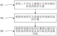
图1为本发明实施例所述的基于磁场特征矢量的定位方法流程图;1 is a flowchart of a method for positioning based on magnetic field feature vectors according to an embodiment of the present invention;
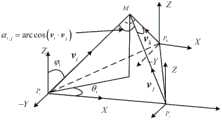
图2为本发明实施例所述的测量磁场与目标关系原理图;2 is a schematic diagram of the relationship between the measurement magnetic field and the target according to an embodiment of the present invention;
图3为本发明实施例所述的基于磁场特征矢量的定位装置的示意图。FIG. 3 is a schematic diagram of a positioning device based on a magnetic field feature vector according to an embodiment of the present invention.
具体实施方式Detailed ways
为使本发明的上述目的、特征和优点能够更为明显易懂,下面结合附图对本发明的具体实施例做详细的说明。In order to make the above objects, features and advantages of the present invention more clearly understood, the specific embodiments of the present invention will be described in detail below with reference to the accompanying drawings.
如图1所示,本发明实施例提供一种基于磁场特征矢量的定位方法,包括:As shown in FIG. 1 , an embodiment of the present invention provides a positioning method based on a magnetic field feature vector, including:
S1,获取三个及以上磁强计分别在磁信标处的特征矢量;S1, obtain the characteristic vectors of three or more magnetometers at the magnetic beacons respectively;
S2,根据所述特征矢量确定所述磁信标的位置;S2, determining the position of the magnetic beacon according to the feature vector;
S3,根据所述磁信标的位置确定磁信标坐标系的相对姿态角以标定所述磁信标。S3: Determine the relative attitude angle of the magnetic beacon coordinate system according to the position of the magnetic beacon to calibrate the magnetic beacon.
具体地,在本实施例中,结合图1和图2所示,基于磁场特征矢量的定位方法,包括:获取多个磁强计在磁信标处的特征矢量;根据特征矢量确定磁信标的位置;根据磁信标的位置确定磁信标坐标系的相对姿态角以标定磁信标,经过先验布置的磁强计测量磁信标的特征矢量,实现实际环境中对磁信标实际磁场中心与坐标系轴线旋转姿态角的高精度估计与标定,从而有效提高导航的定位精度。Specifically, in this embodiment, as shown in FIG. 1 and FIG. 2 , the positioning method based on the magnetic field feature vector includes: acquiring the feature vectors of multiple magnetometers at the magnetic beacon; determining the magnetic beacon according to the feature vector. Position; according to the position of the magnetic beacon, determine the relative attitude angle of the magnetic beacon coordinate system to calibrate the magnetic beacon, and measure the characteristic vector of the magnetic beacon by the magnetometer arranged a priori, so as to realize the comparison between the actual magnetic field center of the magnetic beacon and the actual magnetic field center of the magnetic beacon in the actual environment. The high-precision estimation and calibration of the rotation attitude angle of the coordinate system axis can effectively improve the positioning accuracy of navigation.
在本实施例中,通过设置磁强计测量磁信标的特征矢量,实现实际环境中对磁信标实际磁场中心与坐标系轴线旋转姿态角的高精度估计与标定,从而有效提高导航的定位精度。In this embodiment, by setting the magnetometer to measure the characteristic vector of the magnetic beacon, high-precision estimation and calibration of the actual magnetic field center of the magnetic beacon and the rotational attitude angle of the coordinate system axis in the actual environment are realized, thereby effectively improving the positioning accuracy of navigation .
优选地,所述获取多个磁强计在磁信标处的特征矢量包括:获取磁信标模型,其中,所述磁信标在所述磁信标模型中工作于预设频率;根据所述磁信标的所述预设工作频率确定磁场矢量;根据所述磁场矢量确定各所述磁强计在所述磁信标处的所述特征矢量。Preferably, the acquiring feature vectors of multiple magnetometers at the magnetic beacon includes: acquiring a magnetic beacon model, wherein the magnetic beacon operates at a preset frequency in the magnetic beacon model; The preset operating frequency of the magnetic beacon determines a magnetic field vector; and the characteristic vector of each magnetometer at the magnetic beacon is determined according to the magnetic field vector.
具体地,在本实施例中,获取多个磁强计在磁信标处的特征矢量包括:获取磁信标模型,其中,磁信标在磁信标模型中工作于预设频率,即磁信标模型中的磁信标的工作频率已知;根据磁信标的工作频率确定磁场矢量;根据磁场矢量确定磁强计在磁信标处的特征矢量。Specifically, in this embodiment, acquiring the feature vectors of multiple magnetometers at the magnetic beacon includes: acquiring a magnetic beacon model, wherein the magnetic beacon operates at a preset frequency in the magnetic beacon model, that is, the magnetic beacon model. The working frequency of the magnetic beacon in the beacon model is known; the magnetic field vector is determined according to the working frequency of the magnetic beacon; the characteristic vector of the magnetometer at the magnetic beacon is determined according to the magnetic field vector.
在本实施例中,通过设置磁强计测量磁信标的特征矢量,实现实际环境中对磁信标实际磁场中心与坐标系轴线旋转姿态角的高精度估计与标定,从而有效提高导航的定位精度。In this embodiment, by setting the magnetometer to measure the characteristic vector of the magnetic beacon, high-precision estimation and calibration of the actual magnetic field center of the magnetic beacon and the rotational attitude angle of the coordinate system axis in the actual environment are realized, thereby effectively improving the positioning accuracy of navigation .
优选地,所述磁信标模型的建立过程包括:基于磁偶极子模型,在设定应用环境中设置所述磁信标;将所述磁信标的工作频率设置所述预设频率,建立所述磁信标模型。Preferably, the process of establishing the magnetic beacon model includes: setting the magnetic beacon in a set application environment based on a magnetic dipole model; setting the operating frequency of the magnetic beacon to the preset frequency, and establishing The magnetic beacon model.
具体地,在本实施例中,磁信标模型的建立过程包括:基于磁偶极子模型,在已知应用环境即在预设应用环境中设置磁信标;将磁信标设置为已知的工作频率即预设工作频率,建立所述磁信标模型。Specifically, in this embodiment, the process of establishing the magnetic beacon model includes: based on the magnetic dipole model, setting a magnetic beacon in a known application environment, that is, in a preset application environment; setting the magnetic beacon as a known application environment The working frequency is the preset working frequency, and the magnetic beacon model is established.
在本实施例中,通过设置磁强计测量磁信标的特征矢量,实现实际环境中对磁信标实际磁场中心与坐标系轴线旋转姿态角的高精度估计与标定,从而有效提高导航的定位精度。In this embodiment, by setting the magnetometer to measure the characteristic vector of the magnetic beacon, high-precision estimation and calibration of the actual magnetic field center of the magnetic beacon and the rotational attitude angle of the coordinate system axis in the actual environment are realized, thereby effectively improving the positioning accuracy of navigation .
优选地,所述根据所述磁场矢量确定各所述磁强计在所述磁信标处的所述特征矢量包括:根据所述磁场矢量确定磁场的三轴分量;根据所述三轴分量确定所述磁强计在所述磁信标处的所述特征矢量。Preferably, the determining the characteristic vector of each magnetometer at the magnetic beacon according to the magnetic field vector includes: determining a triaxial component of the magnetic field according to the magnetic field vector; determining according to the triaxial component the eigenvector of the magnetometer at the magnetic beacon.
具体地,在本实施例中,根据磁场矢量确定磁强计在磁信标处的特征矢量包括:根据磁场矢量确定磁场的三轴分量;根据三轴分量确定磁强计在磁信标处的特征矢量。Specifically, in this embodiment, determining the characteristic vector of the magnetometer at the magnetic beacon according to the magnetic field vector includes: determining the triaxial component of the magnetic field according to the magnetic field vector; determining the characteristic vector of the magnetometer at the magnetic beacon according to the triaxial component feature vector.
在本实施例中,通过磁场三轴分量确定磁强计在磁信标处的特征矢量,由于受磁场衰减的影响较弱,具有更强的鲁棒性,从而有效提高导航的定位精度。In this embodiment, the characteristic vector of the magnetometer at the magnetic beacon is determined by the three-axis component of the magnetic field, which is weakly affected by the attenuation of the magnetic field and has stronger robustness, thereby effectively improving the positioning accuracy of navigation.
优选地,所述根据所述特征矢量确定所述磁信标的位置包括:根据第一公式确定所述特征矢量与所述磁信标的位置的关系,所述第一公式包括:
具体地,在本实施例中,根据特征矢量确定磁信标的位置包括:根据第一公式确定特征矢量与磁信标的位置的关系,第一公式包括:
在本实施例中,通过第一公式确定特征矢量与磁信标的位置的关系,从而有效提高导航的定位精度。In this embodiment, the relationship between the feature vector and the position of the magnetic beacon is determined by the first formula, thereby effectively improving the positioning accuracy of navigation.
优选地,所述根据所述特征矢量确定所述磁信标的位置还包括:根据第二公式确定所述磁信标的位置,其中,所述第二公式包括:li=||M-Pi||,lij=||Pi-Pj||,


具体地,在本实施例中,根据特征矢量确定磁信标的位置还包括:根据第二公式确定磁信标的位置,其中,第二公式包括:li=||M-Pi||,lij=||Pi-Pj||,


在本实施例中,通过第二公式确定磁强计的位置,从而有效提高导航的定位精度。In this embodiment, the position of the magnetometer is determined by the second formula, thereby effectively improving the positioning accuracy of navigation.
优选地,所述根据所述磁信标的位置确定磁信标坐标系的相对姿态角包括:根据所述磁信标的位置确定估计特征矢量;根据所述估计特征矢量确定所述磁信标坐标系的旋转矩阵;根据所述旋转矩阵确定所述磁信标坐标系的所述相对姿态角。Preferably, the determining the relative attitude angle of the magnetic beacon coordinate system according to the position of the magnetic beacon includes: determining an estimated feature vector according to the position of the magnetic beacon; determining the magnetic beacon coordinate system according to the estimated feature vector and determining the relative attitude angle of the magnetic beacon coordinate system according to the rotation matrix.
具体地,在本实施例中,根据磁信标的位置确定磁信标坐标系的相对姿态角包括:根据磁信标的位置确定估计特征矢量,根据估计特征矢量确定磁信标坐标系的旋转矩阵,根据旋转矩阵确定磁信标坐标系的相对姿态角。Specifically, in this embodiment, determining the relative attitude angle of the magnetic beacon coordinate system according to the position of the magnetic beacon includes: determining an estimated feature vector according to the position of the magnetic beacon, and determining the rotation matrix of the magnetic beacon coordinate system according to the estimated feature vector, The relative attitude angle of the magnetic beacon coordinate system is determined according to the rotation matrix.
在本实施例中,根据磁信标的位置确定估计特征矢量,根据估计特征矢量确定磁信标坐标系的旋转矩阵,根据旋转矩阵确定磁信标坐标系的相对姿态角,从而有效提高导航的定位精度。In this embodiment, the estimated characteristic vector is determined according to the position of the magnetic beacon, the rotation matrix of the magnetic beacon coordinate system is determined according to the estimated characteristic vector, and the relative attitude angle of the magnetic beacon coordinate system is determined according to the rotation matrix, thereby effectively improving the positioning of navigation. precision.
优选地,所述根据所述旋转矩阵确定所述磁信标坐标系的相对姿态角包括:根据所述旋转矩阵确定所述磁信标坐标系的相对姿态角λ、ψ和γ,其中,λ为所述磁信标坐标系关于X轴的旋转姿态角,ψ为所述磁信标坐标系关于Y轴的旋转姿态角,ψ为所述磁信标坐标系关于Z轴的旋转姿态角。Preferably, the determining the relative attitude angle of the magnetic beacon coordinate system according to the rotation matrix includes: determining the relative attitude angles λ, ψ and γ of the magnetic beacon coordinate system according to the rotation matrix, where λ is the rotational attitude angle of the magnetic beacon coordinate system about the X axis, ψ is the rotational attitude angle of the magnetic beacon coordinate system about the Y axis, and ψ is the rotational attitude angle of the magnetic beacon coordinate system about the Z axis.
具体地,在本实施例中,根据旋转矩阵确定磁信标坐标系的相对姿态角包括:根据旋转矩阵确定磁信标坐标系的相对姿态角λ、ψ和γ,其中,相对姿态角λ为磁信标坐标系关于X轴的旋转姿态角,相对姿态角ψ为磁信标坐标系关于Y轴的旋转姿态角,相对姿态角ψ为磁信标坐标系关于Z轴的旋转姿态角。Specifically, in this embodiment, determining the relative attitude angle of the magnetic beacon coordinate system according to the rotation matrix includes: determining the relative attitude angles λ, ψ and γ of the magnetic beacon coordinate system according to the rotation matrix, where the relative attitude angle λ is The rotation attitude angle of the magnetic beacon coordinate system about the X axis, the relative attitude angle ψ is the rotation attitude angle of the magnetic beacon coordinate system about the Y axis, and the relative attitude angle ψ is the rotation attitude angle of the magnetic beacon coordinate system about the Z axis.
在本实施例中,根据旋转矩阵确定磁信标坐标系的相对姿态角λ、ψ和γ,根据相对姿态角λ、ψ和γ能够有效实现实际环境中对磁信标实际磁场中心与坐标系轴线旋转姿态角的高精度估计与标定,从而有效提高导航的定位精度。In this embodiment, the relative attitude angles λ, ψ and γ of the magnetic beacon coordinate system are determined according to the rotation matrix, and according to the relative attitude angles λ, ψ and γ, the actual magnetic field center and coordinate system of the magnetic beacon in the actual environment can be effectively realized. The high-precision estimation and calibration of the axis rotation attitude angle can effectively improve the positioning accuracy of navigation.
以下为本发明基于磁场特征矢量的定位方法的一个仿真验证例。The following is a simulation verification example of the positioning method based on the magnetic field feature vector of the present invention.
(1)将待标定的磁信标安装在待标定位置,安装固定完毕后,设定磁信标工作频率,将其设定在正常工作状态使其产生时变低频磁场,磁信标的实际待标定中心位置记为M=(mx,my,mz)(M在原点(0m,0m,0m)周围),坐标系关于X、Y、Z轴的旋转姿态角记为λ、ψ、γ(λ=88°、ψ=0°、γ=88°)。在实际应用环境中先安装磁信标再进行标定过程可较好的消除安装误差对磁信标先验信息准确性的影响。(1) Install the magnetic beacon to be calibrated in the position to be calibrated. After the installation is completed, set the working frequency of the magnetic beacon, and set it in the normal working state to generate a time-varying low-frequency magnetic field. The calibration center position is denoted as M=(mx , my , mz ) (M is around the origin (0m, 0m, 0m)), and the rotation attitude angles of the coordinate system about the X, Y, and Z axes are denoted as λ, ψ, γ (λ=88°, ψ=0°, γ=88°). In the actual application environment, installing the magnetic beacon first and then performing the calibration process can better eliminate the influence of the installation error on the accuracy of the prior information of the magnetic beacon.
(2)在待标定磁信标周围布置位置已知、坐标系旋转姿态角的三个高精度磁强计,磁强计的坐标系旋转姿态角一致。三个磁强计的位置记为Pi=(2.0m,2.0m.0.5m),Pj=(-2.0m,2.0m.0.5m),Pk=(-2.0m,-2.0m.0.5m)。磁强计的位置应在最优工作区域,即

(3)计算磁强计处的感应磁场特征矢量,三个磁强计i,j,k处的感应磁场特征矢量为,(3) Calculate the characteristic vector of the induced magnetic field at the magnetometer, the characteristic vector of the induced magnetic field at the three magnetometers i, j, k is,


三个磁强计的测量感应磁场为:


其中,

(4)估计磁信标的中心位置,磁信标中心位置M与磁强计位置Pi,Pj,Pk,满足如下关系:

(5)根据解算得到的磁信标中心位置M=(mx,my,mz),可计算出估计特征矢量:(5) According to the obtained magnetic beacon center position M=(mx , my , mz ), the estimated feature vector can be calculated:

而测量特征矢量i与i′满足关于X,Y,Z轴的旋转关系,即
因此可计算得到磁信标坐标系关于X,Y,Z轴旋转λ、ψ、γ后与磁信标坐标系重合的旋转矩阵:
因此可解得旋转角:So the angle of rotation can be solved:

基于本发明的上述实施例,磁强计实验参数及标定结果如下表1所示,磁信标标定前后目标的导航解算结果对比如下表2所示。Based on the above embodiment of the present invention, the experimental parameters and calibration results of the magnetometer are shown in Table 1 below, and the comparison of the navigation solution results of the target before and after the magnetic beacon calibration is shown in Table 2 below.
表1-磁强计实验参数及标定结果Table 1 - Magnetometer experimental parameters and calibration results

表2-磁信标标定前后目标的导航解算结果对比Table 2 - Comparison of navigation solution results of targets before and after magnetic beacon calibration

由此可见,基于本发明的磁场特征矢量的定位方法,通过设置磁强计测量磁信标的特征矢量,实现实际环境中对磁信标实际磁场中心与坐标系轴线旋转姿态角的高精度估计与标定,从而有效提高导航的定位精度。It can be seen that, based on the positioning method of the magnetic field characteristic vector of the present invention, by setting the magnetometer to measure the characteristic vector of the magnetic beacon, the high-precision estimation of the actual magnetic field center of the magnetic beacon and the rotation attitude angle of the coordinate system axis in the actual environment is realized. calibration, so as to effectively improve the positioning accuracy of navigation.
本发明另一实施例提供一种磁场特征矢量的定位装置,结合图3所示,包括:获取单元,所述获取单元用于获取三个及以上磁强计在磁信标处的特征矢量;处理单元,所述处理单元用于根据所述特征矢量确定所述磁信标的位置,以及根据所述磁信标的位置确定磁信标坐标系的相对姿态角以标定所述磁信标。所述基于磁场特征矢量的定位装置与上述基于磁场特征矢量的定位方法相对于现有技术所具有的优势相同,在此不再赘述。Another embodiment of the present invention provides a device for locating magnetic field feature vectors, which, with reference to FIG. 3 , includes: an acquisition unit, where the acquisition unit is configured to acquire the feature vectors of three or more magnetometers at magnetic beacons; and a processing unit, the processing unit is configured to determine the position of the magnetic beacon according to the feature vector, and determine the relative attitude angle of the magnetic beacon coordinate system according to the position of the magnetic beacon to calibrate the magnetic beacon. The magnetic field feature vector-based positioning device has the same advantages as the above-mentioned magnetic field feature vector-based positioning method relative to the prior art, and details are not described herein again.
本发明另一实施例提供一种磁场特征矢量的定位系统,包括至少三个磁强计以及上述任一所述的基于磁场特征矢量的定位装置。所述基于磁场特征矢量的定位系统与上述基于磁场特征矢量的定位装置相对于现有技术所具有的优势相同,在此不再赘述。Another embodiment of the present invention provides a magnetic field characteristic vector positioning system, including at least three magnetometers and any of the magnetic field characteristic vector-based positioning devices described above. The magnetic field eigenvector-based positioning system has the same advantages as the above-mentioned magnetic field eigenvector-based positioning device relative to the prior art, and details are not described herein again.
虽然本发明公开披露如上,但本发明公开的保护范围并非仅限于此。本领域技术人员在不脱离本发明公开的精神和范围的前提下,可进行各种变更与修改,这些变更与修改均将落入本发明的保护范围。Although the disclosure of the present invention is as above, the protection scope of the disclosure of the present invention is not limited thereto. Those skilled in the art can make various changes and modifications without departing from the spirit and scope of the present disclosure, and these changes and modifications will fall within the protection scope of the present invention.
Claims (10)
Translated fromChinese


Priority Applications (1)
| Application Number | Priority Date | Filing Date | Title |
|---|---|---|---|
| CN202010380081.8ACN111504301B (en) | 2020-05-08 | 2020-05-08 | A positioning method, device and system based on magnetic field feature vector |
Applications Claiming Priority (1)
| Application Number | Priority Date | Filing Date | Title |
|---|---|---|---|
| CN202010380081.8ACN111504301B (en) | 2020-05-08 | 2020-05-08 | A positioning method, device and system based on magnetic field feature vector |
Publications (2)
| Publication Number | Publication Date |
|---|---|
| CN111504301Atrue CN111504301A (en) | 2020-08-07 |
| CN111504301B CN111504301B (en) | 2022-02-18 |
Family
ID=71869837
Family Applications (1)
| Application Number | Title | Priority Date | Filing Date |
|---|---|---|---|
| CN202010380081.8AActiveCN111504301B (en) | 2020-05-08 | 2020-05-08 | A positioning method, device and system based on magnetic field feature vector |
Country Status (1)
| Country | Link |
|---|---|
| CN (1) | CN111504301B (en) |
Cited By (2)
| Publication number | Priority date | Publication date | Assignee | Title |
|---|---|---|---|---|
| CN112504267A (en)* | 2020-11-24 | 2021-03-16 | 哈尔滨工业大学(深圳) | Magnetic fingerprint extraction method, device, system and medium based on magnetic dipole field |
| CN112556683A (en)* | 2020-11-24 | 2021-03-26 | 哈尔滨工业大学(深圳) | Positioning method, device and system based on magnetic dipole field and storage medium |
Citations (11)
| Publication number | Priority date | Publication date | Assignee | Title |
|---|---|---|---|---|
| US5347289A (en)* | 1993-06-29 | 1994-09-13 | Honeywell, Inc. | Method and device for measuring the position and orientation of objects in the presence of interfering metals |
| CN101361660A (en)* | 2008-05-16 | 2009-02-11 | 深圳先进技术研究院 | A positioning method and positioning system for multiple magnetic targets |
| US7498797B1 (en)* | 2005-04-15 | 2009-03-03 | Seektech, Inc. | Locator with current-measuring capability |
| RU2439603C1 (en)* | 2010-05-12 | 2012-01-10 | Открытое акционерное общество "СПЕЦИАЛЬНОЕ КОНСТРУКТОРСКОЕ БЮРО РАДИОИЗМЕРИТЕЛЬНОЙ АППАРАТУРЫ"(ОАО "СКБ РИАП") | Method of detecting and recognising source of electromagnetic radiation |
| CN102927981A (en)* | 2012-10-22 | 2013-02-13 | 中国船舶重工集团公司第七一〇研究所 | Method of locating magnetic target based on tri-axial vector magnetic sensor array |
| CN103954286A (en)* | 2014-04-24 | 2014-07-30 | 南京航空航天大学 | On-orbit iterative calibration method for multi-error model of microsatellite magnetic sensor |
| CN107490802A (en)* | 2017-09-04 | 2017-12-19 | 哈尔滨工业大学 | A kind of space-location method, apparatus and system based on more magnetic beacons |
| WO2018027319A1 (en)* | 2016-08-10 | 2018-02-15 | Andra Motion Technologies | System and method for determining position of a receiver relative to a transmitter |
| US20190130683A1 (en)* | 2017-10-30 | 2019-05-02 | Nxp B.V. | Mobile device, base structure, system and method for recovery of 3d parameters of low frequency magnetic field vectors |
| CN109975880A (en)* | 2019-04-04 | 2019-07-05 | 哈尔滨工业大学 | A kind of orientation method based on characteristic vector, apparatus and system |
| CN110207688A (en)* | 2019-06-25 | 2019-09-06 | 哈尔滨工业大学 | A kind of magnetic beacon fast orienting method and system based on characteristic vector |
- 2020
- 2020-05-08CNCN202010380081.8Apatent/CN111504301B/enactiveActive
Patent Citations (11)
| Publication number | Priority date | Publication date | Assignee | Title |
|---|---|---|---|---|
| US5347289A (en)* | 1993-06-29 | 1994-09-13 | Honeywell, Inc. | Method and device for measuring the position and orientation of objects in the presence of interfering metals |
| US7498797B1 (en)* | 2005-04-15 | 2009-03-03 | Seektech, Inc. | Locator with current-measuring capability |
| CN101361660A (en)* | 2008-05-16 | 2009-02-11 | 深圳先进技术研究院 | A positioning method and positioning system for multiple magnetic targets |
| RU2439603C1 (en)* | 2010-05-12 | 2012-01-10 | Открытое акционерное общество "СПЕЦИАЛЬНОЕ КОНСТРУКТОРСКОЕ БЮРО РАДИОИЗМЕРИТЕЛЬНОЙ АППАРАТУРЫ"(ОАО "СКБ РИАП") | Method of detecting and recognising source of electromagnetic radiation |
| CN102927981A (en)* | 2012-10-22 | 2013-02-13 | 中国船舶重工集团公司第七一〇研究所 | Method of locating magnetic target based on tri-axial vector magnetic sensor array |
| CN103954286A (en)* | 2014-04-24 | 2014-07-30 | 南京航空航天大学 | On-orbit iterative calibration method for multi-error model of microsatellite magnetic sensor |
| WO2018027319A1 (en)* | 2016-08-10 | 2018-02-15 | Andra Motion Technologies | System and method for determining position of a receiver relative to a transmitter |
| CN107490802A (en)* | 2017-09-04 | 2017-12-19 | 哈尔滨工业大学 | A kind of space-location method, apparatus and system based on more magnetic beacons |
| US20190130683A1 (en)* | 2017-10-30 | 2019-05-02 | Nxp B.V. | Mobile device, base structure, system and method for recovery of 3d parameters of low frequency magnetic field vectors |
| CN109975880A (en)* | 2019-04-04 | 2019-07-05 | 哈尔滨工业大学 | A kind of orientation method based on characteristic vector, apparatus and system |
| CN110207688A (en)* | 2019-06-25 | 2019-09-06 | 哈尔滨工业大学 | A kind of magnetic beacon fast orienting method and system based on characteristic vector |
Non-Patent Citations (5)
| Title |
|---|
| JUN-ICHI ITOH等: ""A Comparison between V/f Control and Position-SensorlessVector Control for the Permanent Magnet Synchronous Motor"", 《PCC-OSAKA》* |
| LI, QINGHUA等: ""Quick Orientation of Rotary Magnetic Field Based on Feature Vector"", 《PROCEEDINGS OF THE 38TH CHINESE CONTROL CONFERENCE (CCC) 》* |
| 杨志娟等: ""基于信标的多Agent系统的移动位置研究"", 《长春理工大学学报(自然科学版)》* |
| 王煜: ""基于特征矢量的磁信标定位技术"", 《中国优秀硕士学位论文全文数据库基础科学辑》* |
| 谢阳光等: ""基于双磁偶极子的螺线管磁场建模分析"", 《中国惯性技术学报》* |
Cited By (4)
| Publication number | Priority date | Publication date | Assignee | Title |
|---|---|---|---|---|
| CN112504267A (en)* | 2020-11-24 | 2021-03-16 | 哈尔滨工业大学(深圳) | Magnetic fingerprint extraction method, device, system and medium based on magnetic dipole field |
| CN112556683A (en)* | 2020-11-24 | 2021-03-26 | 哈尔滨工业大学(深圳) | Positioning method, device and system based on magnetic dipole field and storage medium |
| CN112556683B (en)* | 2020-11-24 | 2023-02-24 | 哈尔滨工业大学(深圳) | Positioning method, device and system based on magnetic dipole field and storage medium |
| CN112504267B (en)* | 2020-11-24 | 2023-03-14 | 哈尔滨工业大学(深圳) | Magnetic fingerprint extraction method, device, system and medium based on magnetic dipole field |
Also Published As
| Publication number | Publication date |
|---|---|
| CN111504301B (en) | 2022-02-18 |
Similar Documents
| Publication | Publication Date | Title |
|---|---|---|
| CN104776865B (en) | The electromagnetic tracking system and method quickly determined based on maximum magnetic induction Vector Rotation angle | |
| CN109883415A (en) | A Rotating Magnetic Field Positioning Method Based on Trigonometric Function Fitting | |
| CN103575271B (en) | Electromagnetic tracking system based on automatically controlled rotating excitation field and method | |
| CN104976948B (en) | Magnetoresistive angle-sensor configuration and the sensing system for using the sensor | |
| CN106643792B (en) | Inertial measurement unit and geomagnetic sensor integral calibration device and calibration method | |
| CN104535062B (en) | Campaign-styled localization method based on magnetic gradient tensor sum earth magnetism vector measurement | |
| CN111504301B (en) | A positioning method, device and system based on magnetic field feature vector | |
| CN108227005A (en) | A kind of target positioning and recognition methods | |
| CN113514789B (en) | A magnetic sensor array calibration method | |
| CN111664778B (en) | External field robust angle sensing using differential magnetic fields | |
| CN111551996A (en) | A real-time localization method for cooperative magnetic targets based on magnetic tensor | |
| CN102426392A (en) | Electromagnetic tracking method based on quadrature magnetic bar rotation search and system thereof | |
| CN109059960B (en) | A kind of calibration method of three-dimensional electronic compass | |
| CN110736484B (en) | Calibration method of background magnetic field based on fusion of gyroscope and magnetic sensor | |
| CN115096294B (en) | Multi-parameter underwater magnetic target positioning method | |
| CN111504318A (en) | A marine navigation aid method based on multi-magnetic dipole inversion | |
| US20230160929A1 (en) | Coreless auto-calibrating current sensor for measuring current in an adjacent wire | |
| CN109633540B (en) | A real-time positioning system and real-time positioning method of a magnetic source | |
| CN115524762A (en) | Compensation method of geomagnetic vector measurement system based on three-dimensional Helmertz coil | |
| CN109975840A (en) | A kind of Nulling antenna satellite navigation receiver positioning correction method | |
| CN116609839B (en) | A variable structure underwater ferromagnetic anomaly positioning method based on magnetic gradient tensor | |
| JP4452868B2 (en) | Measurement method in magnetic motion capture device | |
| KR20170092356A (en) | System for calibrating azimuth of 3-axis magnetic sensor | |
| Cui et al. | Three-axis magnetometer calibration based on optimal ellipsoidal fitting under constraint condition for pedestrian positioning system using foot-mounted inertial sensor/magnetometer | |
| Li et al. | An efficient method for tri-axis magnetometer calibration |
Legal Events
| Date | Code | Title | Description |
|---|---|---|---|
| PB01 | Publication | ||
| PB01 | Publication | ||
| SE01 | Entry into force of request for substantive examination | ||
| SE01 | Entry into force of request for substantive examination | ||
| GR01 | Patent grant | ||
| GR01 | Patent grant |