CN111498137A - Staying unmanned aerial vehicle controlling means - Google Patents
Staying unmanned aerial vehicle controlling meansDownload PDFInfo
- Publication number
- CN111498137A CN111498137ACN202010533961.4ACN202010533961ACN111498137ACN 111498137 ACN111498137 ACN 111498137ACN 202010533961 ACN202010533961 ACN 202010533961ACN 111498137 ACN111498137 ACN 111498137A
- Authority
- CN
- China
- Prior art keywords
- frame
- power supply
- control circuit
- negative
- inner frame
- Prior art date
- Legal status (The legal status is an assumption and is not a legal conclusion. Google has not performed a legal analysis and makes no representation as to the accuracy of the status listed.)
- Granted
Links
Images
Classifications
- B—PERFORMING OPERATIONS; TRANSPORTING
- B64—AIRCRAFT; AVIATION; COSMONAUTICS
- B64F—GROUND OR AIRCRAFT-CARRIER-DECK INSTALLATIONS SPECIALLY ADAPTED FOR USE IN CONNECTION WITH AIRCRAFT; DESIGNING, MANUFACTURING, ASSEMBLING, CLEANING, MAINTAINING OR REPAIRING AIRCRAFT, NOT OTHERWISE PROVIDED FOR; HANDLING, TRANSPORTING, TESTING OR INSPECTING AIRCRAFT COMPONENTS, NOT OTHERWISE PROVIDED FOR
- B64F3/00—Ground installations specially adapted for captive aircraft
- G—PHYSICS
- G05—CONTROLLING; REGULATING
- G05D—SYSTEMS FOR CONTROLLING OR REGULATING NON-ELECTRIC VARIABLES
- G05D1/00—Control of position, course, altitude or attitude of land, water, air or space vehicles, e.g. using automatic pilots
- G05D1/10—Simultaneous control of position or course in three dimensions
- G05D1/101—Simultaneous control of position or course in three dimensions specially adapted for aircraft
Landscapes
- Engineering & Computer Science (AREA)
- Aviation & Aerospace Engineering (AREA)
- Radar, Positioning & Navigation (AREA)
- Remote Sensing (AREA)
- Physics & Mathematics (AREA)
- General Physics & Mathematics (AREA)
- Automation & Control Theory (AREA)
- Structures Of Non-Positive Displacement Pumps (AREA)
- Forklifts And Lifting Vehicles (AREA)
Abstract
Translated fromChinese
Description
Translated fromChinese技术领域technical field
本发明涉及无人机控制设备技术领域,特别一种系留无人机控制装置。The invention relates to the technical field of unmanned aerial vehicle control equipment, in particular to a tethered unmanned aerial vehicle control device.
背景技术Background technique
系留无人机因有系留绳的存在,地面设备经线缆为无人机供电,能实现无人机24小时全天时续航,完美解决了普通无人机的续航问题,且具有载荷大、成本低的优点,在抗洪救灾应急通信、重大活动安全保障、大型集会长时间定点监控等方面应用越来越多。在GPS或其它卫星导航的模式下,系留机可以精准控制悬停的水平精度,但是,在有特殊需要关掉GPS或者其它卫星导航模式,或者强电磁对抗,或者受到强干扰的情况下,有可能导致无人机偏航,也就是说无法在地面人员设定的空域位置内悬停,进而对其有效应用带来一定制约。Due to the existence of the tethered UAV, the ground equipment supplies power to the UAV through the cable, which can realize the 24-hour battery life of the UAV, which perfectly solves the battery life problem of ordinary UAVs and has a load. The advantages of large size and low cost are used more and more in flood-fighting and disaster-relief emergency communications, safety assurance of major events, and long-term fixed-point monitoring of large-scale gatherings. In GPS or other satellite navigation modes, the tethered aircraft can precisely control the horizontal accuracy of hovering. However, in the case of special needs to turn off GPS or other satellite navigation modes, or strong electromagnetic countermeasures, or strong interference, It may cause the UAV to yaw, that is to say, it cannot hover in the airspace position set by the ground personnel, which will impose certain restrictions on its effective application.
现有技术中,发生系留无人机偏航时,通常是操作人员在地面进行纠偏操作,控制无人机再次飞回到设定的空域,由于需要人为操作,会给操作人员带来不便,且操作人员不能实时发现无人机偏航,因此并不能有效保证无人机时刻处于设定的空域悬停。基于上述,提供一种不需要人为控制,能实时监测无人机是否偏航,且在偏航时能及时纠偏的控制装置显得尤为必要。In the prior art, when a tethered drone yaw occurs, the operator usually performs a yaw correction operation on the ground, and controls the drone to fly back to the set airspace again. Since manual operation is required, it will bring inconvenience to the operator. , and the operator cannot detect the yaw of the drone in real time, so it cannot effectively ensure that the drone is hovering in the set airspace at all times. Based on the above, it is particularly necessary to provide a control device that does not require human control, can monitor whether the drone is yaw in real time, and can correct the deviation in time when the drone is yaw.
发明内容SUMMARY OF THE INVENTION
为了克服现有系留无人机偏航时,由于是人为操作纠偏,会给操作人员带来不便,以及因操作人员不能实时发现无人机偏航,不能有效保证无人机时刻处于设定空域悬停的弊端,本发明提供了是实现多角度实时监测系留无人机是否偏航,且在发生偏航时,在相关机构共同作用下,能及时反方向调整系留无人机的悬停位置,从而达到尽可能保证系留无人机处于设定空域悬停的一种系留无人机控制装置。In order to overcome the yaw of the existing tethered UAV, it will bring inconvenience to the operator due to the manual operation to correct the deviation, and because the operator cannot detect the yaw of the UAV in real time, it cannot effectively ensure that the UAV is always in the setting The disadvantages of hovering in the airspace, the present invention provides the realization of multi-angle real-time monitoring of whether the tethered UAV is yaw, and when the yaw occurs, under the joint action of relevant institutions, the tethered UAV can be adjusted in the opposite direction in time. A tethered UAV control device that ensures that the tethered UAV hovers in the set airspace as much as possible.
本发明解决其技术问题所采用的技术方案是:The technical scheme adopted by the present invention to solve its technical problems is:
一种系留无人机控制装置,包括稳压电源、轴流风扇,其特征在于还具有方位探测设备、控制电路;所述轴流风扇有相同的两套,两套轴流风扇分别安装在系留无人机的机体下两侧;所述方位探测设备包括机架、外框、内框,外框及内框中部均为空心结构;所述内框配套有内滑板,内滑板的前后侧端分别有内滑条,内框的前后内侧端分别有内滑槽,内滑条位于内滑槽的槽内;所述内滑板的左右侧端上各有磁铁;所述内框的内左右侧端各有干簧管;所述内框的外左右侧端各有外滑条;所述外框的左右内侧端分别有外滑槽,外滑条位于外滑槽的槽内;所述内框前后侧端上各有磁铁;所述外框的内前后侧端各有干簧管;所述系留无人机本体的系留绳下端和内滑板安装在一起;所述外框的下端安装在机架的上端;所述稳压电源、控制电路安装在元件盒内;所述稳压电源的输出端正极和四只干簧管一端电性连接,四只干簧管另一端和控制电路的四个信号输入端分别电性连接;所述稳压电源的正极电源输出端和控制电路的正极控制电源输入端电性连接,稳压电源的负极电源输出端和控制电路的负极及负极控制电源输入端电性连接;所述控制电路的第一及第二路电源输出端和系留无人机本体下其中一端的轴流风扇正负两极、负正两极电源输入端分别电性连接,所述控制电路的第三及第四路电源输出端和系留无人机本体下另一端的轴流风扇正负两极、负正两极电源输入端分别电性连接。A tethered unmanned aerial vehicle control device, comprising a regulated power supply and an axial flow fan, and is characterized in that it also has an orientation detection device and a control circuit; the axial flow fan has two identical sets, and the two sets of axial flow fans are respectively installed in The lower two sides of the body of the tethered drone; the orientation detection equipment includes a frame, an outer frame, and an inner frame, and the inner part of the outer frame and the inner frame are hollow structures; the inner frame is equipped with an inner sliding plate, and the front and rear of the inner sliding plate are The side ends are respectively provided with inner sliding bars, the front and rear inner ends of the inner frame are respectively provided with inner sliding grooves, and the inner sliding bars are located in the grooves of the inner sliding grooves; the left and right side ends of the inner slide plate are respectively provided with magnets; The left and right side ends are respectively provided with reed switches; the outer left and right side ends of the inner frame are respectively provided with outer sliding bars; the left and right inner ends of the outer frame are respectively provided with outer sliding grooves, and the outer sliding bars are located in the grooves of the outer sliding grooves; There are magnets on the front and rear side ends of the inner frame; reed switches are arranged on the inner front and rear side ends of the outer frame; the lower end of the mooring rope of the tethered drone body is installed with the inner slide plate; the outer frame The lower end of the regulated power supply and the control circuit are installed in the component box; the positive pole of the output end of the regulated power supply is electrically connected to one end of the four reed switches, and the other end of the four reed switches is electrically connected. and the four signal input terminals of the control circuit are respectively electrically connected; the positive power output terminal of the regulated power supply is electrically connected to the positive control power input terminal of the control circuit, and the negative power output terminal of the regulated power supply is electrically connected to the negative terminal of the control circuit. and the negative control power supply input terminal is electrically connected; the first and second power supply output terminals of the control circuit and the positive and negative poles and the negative and positive poles power supply input terminals of the axial flow fan at one end of the tethered drone body are respectively electrically connected. The third and fourth power output terminals of the control circuit are electrically connected to the positive and negative poles and the negative and positive poles of the power supply input terminals of the axial flow fan at the other end of the tethered drone body, respectively.
进一步地,所述稳压电源是交流转直流开关电源模块。Further, the regulated power supply is an AC-to-DC switching power supply module.
进一步地,所述内框的外侧长宽度小于外框内侧空心部位的长宽度。Further, the outer length and width of the inner frame is smaller than the length and width of the inner hollow portion of the outer frame.
进一步地,所述内滑板的外侧长宽度小于内框内侧空心部位的长宽度。Further, the outer length and width of the inner slide plate are smaller than the length and width of the inner hollow part of the inner frame.
进一步地,所述四只干簧管的内部动触点和静触点为常开式结构。Further, the internal moving contacts and static contacts of the four reed switches are normally open structures.
进一步地,所述控制电路是四只继电器,其间经电路板布线连接,四只继电器正极控制电源输入端连接,四只继电器负极及负极控制电源输入端连接。Further, the control circuit is composed of four relays, which are connected by circuit board wiring, the positive poles of the four relays are connected to the power supply input terminals, and the negative poles and the negative poles of the four relays are connected to the power supply input terminals.
本发明有益效果是:本发明工作时,不需要人为操作,当系留无人机向左或向右发生偏航时,系留绳下端会带动内滑板向左或向右运动,进而内框左右侧的干簧管内部触点分别接通,在控制电路作用下,系留无人机本体左端的轴流风扇正负两极或负正两极电源输入端分别得电,产生向右拉力或向左拉力,尽可能保持系留无人机左右航向处于使用者放飞无人机时设定的空域。当系留无人机向前或向后发生偏航时,系留绳下端会带动内框向前或向后运动,进而外框前后侧的干簧管内部触点分别接通,在控制电路作用下,系留无人机本体前端的轴流风扇正负两极或负正两极电源输入端分别得电,产生向后拉力或向前拉力,尽可能保持系留无人机前后航向处于使用者放飞无人机时设定的空域。通过上述机构及电路共同作用,本发明能实现多角度实时监测系留无人机是否偏航,且在发生偏航时,在相关机构共同作用下,能及时反方向调整系留无人机的悬停位置,从而达到尽可能保证系留无人机处于设定空域悬停。基于上述,所以本发明具有好的应用前景。The beneficial effects of the present invention are: when the present invention works, no human operation is required, and when the mooring drone yaw to the left or right, the lower end of the mooring rope will drive the inner slide plate to move left or right, and then the inner frame The internal contacts of the left and right reed switches are respectively connected. Under the action of the control circuit, the positive and negative poles or the negative and positive poles of the power input terminals of the axial flow fan on the left end of the tethered drone body are respectively powered to generate a rightward pulling force or a downward direction. Pull to the left and try to keep the left and right headings of the tethered drone in the airspace set by the user when the drone is released. When the tethered drone yaw forward or backward, the lower end of the tethered rope will drive the inner frame to move forward or backward, and then the internal contacts of the reed switches on the front and rear sides of the outer frame are respectively connected, and the control circuit Under the action, the positive and negative poles or the power input terminals of the negative and positive poles of the axial flow fan at the front end of the tethered drone body are respectively powered to generate a backward pulling force or a forward pulling force, so as to keep the front and rear heading of the tethered drone as close to the user as possible. The airspace set when the drone is launched. Through the joint action of the above mechanisms and circuits, the present invention can realize multi-angle real-time monitoring of whether the tethered UAV is yaw, and when the yaw occurs, under the joint action of the relevant mechanisms, the tethered UAV can be adjusted in the opposite direction in time. Hover position, so as to ensure that the tethered drone hovers in the set airspace as much as possible. Based on the above, the present invention has a good application prospect.
附图说明Description of drawings
以下结合附图和实施例将本发明做进一步说明。The present invention will be further described below with reference to the accompanying drawings and embodiments.
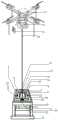
图1是本发明结构示意图。Figure 1 is a schematic structural diagram of the present invention.
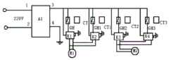
图2是本发明方位探测设备的结构示意图。FIG. 2 is a schematic structural diagram of the azimuth detection device of the present invention.
具体实施方式Detailed ways
图1中所示,一种系留无人机控制装置,包括稳压电源1、轴流风扇21及22,还具有方位探测设备3、控制电路4;所述轴流风扇有相同的两套,两套轴流风扇21及22框架上端分别经螺杆螺母垂直安装在系留无人机13的机体下左端及下前端中部;所述方位探测设备3包括矩形机架31、矩形外框32、矩形内框33,外框32及内框33中部均为空心结构;所述内框33配套有一只内滑板34,内滑板34的前后侧端中部各有一只一体成型的矩形内滑条35,内框33的前后内侧端分别横向具有一道内滑槽36,内滑板34的前后侧端内滑条35分别位于内框前后内侧端的内滑槽36的槽内,内滑板34能经内滑条沿内滑槽36左右滑动;所述内滑板36的左右侧端上中部各纵向用胶粘接有一只条形永久磁铁5及6;所述内框33的内左右侧端中部各纵向用胶粘接有一只干簧管7及8;所述内框33的外左右侧端中部各有一只一体成型的矩形外滑条37;所述外框32的左右内侧端分别纵向具有一道外滑槽38,内框33的外左右侧端中部外滑条37分别位于外框左右内侧端外滑槽38的槽内;所述内框33前后侧端上中部各横向用胶粘接有一只条形永久磁铁9及10;所述外框32的内前后侧端中部各横向用胶粘接有一只干簧管11及12;所述系留无人机本体13的系留绳14下端和内滑板34中部开孔经螺杆螺母固定在一起;所述外框32的下端四周经螺杆螺母安装在机架31的上端四周,机架安装在地面上;所述稳压电源1、控制电路4安装在元件盒15内,元件盒15安装在机架31的前左端。内框33的外侧长宽度小于外框32内侧空心部位的长宽度(前后小于9cm、左右小于1cm)。内滑板36的外侧长宽度小于内框33内侧空心部位的长宽度(左右小于9cm、前后小于1cm)。As shown in FIG. 1, a tethered drone control device includes a regulated
图2所示,稳压电源A1是交流220V转24V直流开关电源模块成品,功率1KW(型号是LRS-1000-24)。轴流风扇M1、M2每套功率50W,工作电压直流24V。四只干簧管GH、GH1、GH2、GH3的内部动触点和静触点为常开式结构,干簧管GH、GH1、GH2、GH3的动触点水平位于内框33及外框32的外侧。控制电路是四只继电器K1、K2、K3、K4,其间经电路板布线连接,四只继电器K1、K2、K3、K4正极控制电源输入端连接,四只继电器K1、K2、K3、K4负极及负极控制电源输入端连接。稳压电源A1电源输入两端1及2脚和交流220V电源两极分别经导线连接,稳压电源A1的输出端正极3脚和四只干簧管GH、GH1、GH2、GH3一端经导线连接,四只干簧管GH、GH1、GH2、GH3另一端和控制电路的四个信号输入端四只继电器K1、K2、K3、K4正极电源输入端分别经导线连接;所述稳压电源A1的正极电源输出端3脚和控制电路的四只继电器K1、K2、K3、K4正极控制电源输入端经导线连接,稳压电源A1的负极电源输出端4脚和控制电路的四只继电器K1、K2、K3、K4负极及负极控制电源输入端经导线连接;所述控制电路的第一及第二路电源输出端继电器K1、K2两个常开触点端和系留无人机本体下左端的轴流风扇M1正负两极、负正两极电源输入端分别经导线连接,所述控制电路的第三及第四路电源输出端继电器K3、K4两个常开触点端和系留无人机本体下前端的轴流风扇M2正负两极、负正两极电源输入端分别经导线连接。As shown in Figure 2, the regulated power supply A1 is a finished product of an
图1、2所示,220V交流电源进入稳压电源A1的1及2脚后,稳压电源A1的3及4脚会输出稳定的24V直流电源进入控制电源电源输入两端以及四只干簧管GH、GH1、GH2、GH3的正极电源输入端。系留无人机本体13没有偏航时和内滑板34之间处于接近垂直状态,那么内滑板34不会发生左右运动,内框33不会发生前后运动,四只干黄管内部触点均处于开路状态,两套轴流风扇均不会得电工作。实际情况下,当因各种原因,系留无人机向左发生偏航时,系留绳下端会带动内滑板34经内滑条35沿内滑槽36向左运动,向左偏航较多时,内滑板34运动的距离较大,于是其左上端的磁铁CT接近干簧管GH,干簧管GH内部触点受到磁性作用力闭合,进而继电器K1得电吸合其两个控制电源输入端和两个常开触点端分别闭合。由于,继电器K1两个常开触点端和系留无人机本体下左端的轴流风扇M1正负两极电源输入端分别经导线连接,所以此刻轴流风扇M1正负两极得电后其叶片会顺时针转动,进而产生朝向右侧的拉力,带动系留无人机本体13整体向右侧端运动;同时无人机本体的系留绳带动内滑板34向右侧运动,当系留无人机本体13向右侧纠偏达到一定位置后,内滑板34向右侧运动到合适位置,那么磁铁CT的磁性作用力不再作用于干簧管GH,干簧管GH内部触点开路,进而,轴流风扇M1不再工作,无人机本体13也不再朝向右端运动,完成无人机本体13左偏后的纠偏全部程序。As shown in Figures 1 and 2, after the 220V AC power enters the 1 and 2 pins of the regulated power supply A1, the 3 and 4 pins of the regulated power supply A1 will output a stable 24V DC power supply to the input terminals of the control power supply and four reeds. Positive power input terminals of tubes GH, GH1, GH2, GH3. When the tethered
图1、2中所示,实际情况下,当因各种原因,系留无人机向右发生偏航时,系留绳下端会带动内滑板34经内滑条35沿内滑槽36向右运动,向右偏航较多时,内滑板34运动的距离较大,于是其右上端的磁铁CT1接近干簧管GH1,干簧管GH1内部触点受到磁性作用力闭合,进而继电器K2得电吸合其两个控制电源输入端和两个常开触点端分别闭合。由于,继电器K2两个常开触点端和系留无人机本体下左端的轴流风扇M1负正两极电源输入端分别经导线连接,所以此刻轴流风扇M1负正两极得电后其叶片会逆时针转动,进而产生朝向左侧的拉力,带动系留无人机本体13整体向左侧端运动;同时无人机本体的系留绳带动内滑板34向左侧运动,当系留无人机本体13向左侧纠偏达到一定位置后,内滑板34向左侧运动到合适位置,那么磁铁CT1的磁性作用力不再作用于干簧管GH1,干簧管GH1内部触点开路,进而,轴流风扇M1不再工作,无人机本体13也不再朝向左端运动,完成无人机本体13右偏后的纠偏全部程序。As shown in Figures 1 and 2, in actual situations, when the tethered drone yaw to the right due to various reasons, the lower end of the tethered rope will drive the
图1、2所示,实际情况下,当因各种原因,系留无人机向前发生偏航时,系留绳下端会经内滑板34带动内框33整体经外滑条37沿外滑槽38向前运动,向前偏航较多时,内框33运动的距离较大,于是其前上端的磁铁CT2接近干簧管GH2,干簧管GH2内部触点受到磁性作用力闭合,进而继电器K3得电吸合其两个控制电源输入端和两个常开触点端分别闭合。由于,继电器K3两个常开触点端和系留无人机本体下前端的轴流风扇M2正负两极电源输入端分别经导线连接,所以此刻轴流风扇M2正负两极得电后其叶片会顺时针转动,进而产生朝向后侧的拉力,带动系留无人机本体13整体向后侧端运动;同时无人机本体的系留绳带动内框33向后侧运动,当系留无人机本体13向后侧纠偏达到一定位置后,内框33向后侧运动到合适位置,那么磁铁CT2的磁性作用力不再作用于干簧管GH2,干簧管GH2内部触点开路,进而,轴流风扇M2不再工作,无人机本体13也不再朝向后端运动,完成无人机本体1前偏后的纠偏全部程序。As shown in Figures 1 and 2, in actual situations, when the mooring drone yaw forward due to various reasons, the lower end of the mooring rope will drive the
图1、2所示,实际情况下,当因各种原因,系留无人机向后发生偏航时,系留绳下端会经内滑板34带动内框33整体经外滑条37沿外滑槽38向后运动,向后偏航较多时,内框33运动的距离较大,于是其后上端的磁铁CT3接近干簧管GH3,干簧管GH3内部触点受到磁性作用力闭合,进而继电器K4得电吸合其两个控制电源输入端和两个常开触点端分别闭合。由于,继电器K4两个常开触点端和系留无人机本体下前端的轴流风扇M2负正两极电源输入端分别经导线连接,所以此刻轴流风扇M2负正两极得电后其叶片会逆时针转动,进而产生朝向前侧的拉力,带动系留无人机本体13整体向前侧端运动;同时无人机本体的系留绳带动内框33向前侧运动,当系留无人机本体13向前侧纠偏达到一定位置后,内框33向前侧运动到合适位置,那么磁铁CT3的磁性作用力不再作用于干簧管GH3,干簧管GH3内部触点开路,进而,轴流风扇M2不再工作,无人机本体13也不再朝向前端运动,完成无人机本体1后偏后的纠偏全部程序。继电器K1、K2、K3、K4是DC24V继电器;干簧管GH、GH1、GH2、GH3是玻璃外壳常闭触点型干簧管(型号MKA14103)。As shown in Figures 1 and 2, in actual circumstances, when the tethered drone yaw backwards due to various reasons, the lower end of the tethered rope will drive the entire
以上显示和描述了本发明的基本原理和主要特征及本发明的优点,对于本领域技术人员而言,显然本发明限于上述示范性实施例的细节,而且在不背离本发明的精神或基本特征的情况下,能够以其他的具体形式实现本发明。因此,无论从哪一点来看,均应将实施例看作是示范性的,而且是非限制性的,本发明的范围由所附权利要求而不是上述说明限定,因此旨在将落在权利要求的等同要件的含义和范围内的所有变化囊括在本发明内。While the basic principles and main features and advantages of the present invention have been shown and described above, it will be apparent to those skilled in the art that the present invention is limited to the details of the above-described exemplary embodiments without departing from the spirit or essential characteristics of the present invention. In this case, the present invention can be implemented in other specific forms. Therefore, the embodiments are to be regarded in all respects as illustrative and not restrictive, and the scope of the invention is to be defined by the appended claims rather than the foregoing description, which are therefore intended to fall within the scope of the claims. All changes within the meaning and scope of the equivalents of , are included in the present invention.
此外,应当理解,虽然本说明书按照实施方式加以描述,但并非实施方式仅包含一个独立的技术方案,说明书的这种叙述方式仅仅是为清楚起见,本领域技术人员应当将说明书作为一个整体,实施例中的技术方案也可以经适当组合,形成本领域技术人员可以理解的其他实施方式。In addition, it should be understood that although this specification is described according to an embodiment, it does not mean that the embodiment only includes an independent technical solution. This description in the specification is only for the sake of clarity. Those skilled in the art should take the specification as a whole and implement the The technical solutions in the examples can also be appropriately combined to form other embodiments that can be understood by those skilled in the art.
Claims (6)
Translated fromChinesePriority Applications (1)
| Application Number | Priority Date | Filing Date | Title |
|---|---|---|---|
| CN202010533961.4ACN111498137B (en) | 2020-06-12 | 2020-06-12 | A tethered drone control device |
Applications Claiming Priority (1)
| Application Number | Priority Date | Filing Date | Title |
|---|---|---|---|
| CN202010533961.4ACN111498137B (en) | 2020-06-12 | 2020-06-12 | A tethered drone control device |
Publications (2)
| Publication Number | Publication Date |
|---|---|
| CN111498137Atrue CN111498137A (en) | 2020-08-07 |
| CN111498137B CN111498137B (en) | 2025-03-21 |
Family
ID=71865668
Family Applications (1)
| Application Number | Title | Priority Date | Filing Date |
|---|---|---|---|
| CN202010533961.4AActiveCN111498137B (en) | 2020-06-12 | 2020-06-12 | A tethered drone control device |
Country Status (1)
| Country | Link |
|---|---|
| CN (1) | CN111498137B (en) |
Cited By (1)
| Publication number | Priority date | Publication date | Assignee | Title |
|---|---|---|---|---|
| CN112947552A (en)* | 2020-12-31 | 2021-06-11 | 西安爱生无人机技术有限公司 | Unmanned aerial vehicle cluster auxiliary control device |
Citations (6)
| Publication number | Priority date | Publication date | Assignee | Title |
|---|---|---|---|---|
| CN107364769A (en)* | 2017-07-18 | 2017-11-21 | 深圳市景宏光电科技有限公司 | A kind of intelligent extension and retraction system for being applied to be tethered at unmanned plane |
| US20180109223A1 (en)* | 2016-10-17 | 2018-04-19 | Aetherix Corporation | Airborne renewable energy generation and storage |
| US20180130017A1 (en)* | 2016-07-27 | 2018-05-10 | Aniruddha Rajendra Gupte | System and method to enable delivery and pick up of packages using pods and unmanned vehicles |
| CN108821036A (en)* | 2018-07-02 | 2018-11-16 | 合肥瀚翔智能科技有限公司 | One kind being tethered at unmanned plane with full-automatic hawser draw off gear |
| WO2019090865A1 (en)* | 2017-11-08 | 2019-05-16 | 珠海市双捷科技有限公司 | Tethered ground station and tethered drone system |
| CN212243879U (en)* | 2020-06-12 | 2020-12-29 | 珠海市双捷科技有限公司 | Staying unmanned aerial vehicle controlling means |
- 2020
- 2020-06-12CNCN202010533961.4Apatent/CN111498137B/enactiveActive
Patent Citations (6)
| Publication number | Priority date | Publication date | Assignee | Title |
|---|---|---|---|---|
| US20180130017A1 (en)* | 2016-07-27 | 2018-05-10 | Aniruddha Rajendra Gupte | System and method to enable delivery and pick up of packages using pods and unmanned vehicles |
| US20180109223A1 (en)* | 2016-10-17 | 2018-04-19 | Aetherix Corporation | Airborne renewable energy generation and storage |
| CN107364769A (en)* | 2017-07-18 | 2017-11-21 | 深圳市景宏光电科技有限公司 | A kind of intelligent extension and retraction system for being applied to be tethered at unmanned plane |
| WO2019090865A1 (en)* | 2017-11-08 | 2019-05-16 | 珠海市双捷科技有限公司 | Tethered ground station and tethered drone system |
| CN108821036A (en)* | 2018-07-02 | 2018-11-16 | 合肥瀚翔智能科技有限公司 | One kind being tethered at unmanned plane with full-automatic hawser draw off gear |
| CN212243879U (en)* | 2020-06-12 | 2020-12-29 | 珠海市双捷科技有限公司 | Staying unmanned aerial vehicle controlling means |
Cited By (2)
| Publication number | Priority date | Publication date | Assignee | Title |
|---|---|---|---|---|
| CN112947552A (en)* | 2020-12-31 | 2021-06-11 | 西安爱生无人机技术有限公司 | Unmanned aerial vehicle cluster auxiliary control device |
| CN112947552B (en)* | 2020-12-31 | 2021-11-12 | 西安爱生无人机技术有限公司 | Unmanned aerial vehicle cluster auxiliary control device |
Also Published As
| Publication number | Publication date |
|---|---|
| CN111498137B (en) | 2025-03-21 |
Similar Documents
| Publication | Publication Date | Title |
|---|---|---|
| CN207354057U (en) | A kind of switch driving circuit, battery control circuit, battery and unmanned plane | |
| CN207433831U (en) | Unmanned plane charging unit and wind power generating set | |
| CN204871616U (en) | Wired unmanned aerial vehicle driving system of high -power high voltage electric drive | |
| CN101627752A (en) | Solar-energy machine eagle | |
| CN106043701B (en) | A kind of new unmanned plane for being used for agricultural and pouring based on Internet of Things | |
| CN103560039A (en) | High-voltage breaker permanent magnet salient pole motor operation mechanism and control method | |
| CN111498137A (en) | Staying unmanned aerial vehicle controlling means | |
| CN212243879U (en) | Staying unmanned aerial vehicle controlling means | |
| CN114475298A (en) | Magnetic chuck charging contact connecting device and unmanned aerial vehicle charging method | |
| CN104477385B (en) | A kind of unmanned flapping wing aircraft | |
| CN104097790B (en) | A kind of spacecraft steering unit adjustment method | |
| CN110700668B (en) | A solar powered smart drone hangar | |
| CN204037899U (en) | Solar power vertically taking off and landing flyer during long boat | |
| CN110687924A (en) | Novel flap control system of large and medium-sized unmanned aerial vehicle | |
| CN110615098A (en) | Aircraft and aircraft control method | |
| CN207311837U (en) | A kind of long endurance solar energy unmanned plane | |
| CN206544600U (en) | A drone that can be used to deliver items remotely | |
| CN209581875U (en) | A kind of combined dual-purpose unmanned plane | |
| CN205212472U (en) | A single power supply system for electronic unmanned aerial vehicle | |
| CN114906336B (en) | Transient energy management device and method for ram air turbine power generation system | |
| CN111516896B (en) | A closed-loop line loss compensation device for a tethered drone system | |
| CN212243881U (en) | Staying unmanned aerial vehicle system's closed loop line loss compensation arrangement | |
| CN107323659A (en) | A kind of Intelligent unattended machine for being easy to store based on Internet of Things | |
| CN217805337U (en) | Flight control test bench and test system | |
| CN215895281U (en) | Control device of spherical robot |
Legal Events
| Date | Code | Title | Description |
|---|---|---|---|
| PB01 | Publication | ||
| PB01 | Publication | ||
| SE01 | Entry into force of request for substantive examination | ||
| SE01 | Entry into force of request for substantive examination | ||
| GR01 | Patent grant | ||
| GR01 | Patent grant |