CN111497243B - Additive manufacturing system and method for build plate clamping assembly and additive printing on workpiece - Google Patents
Additive manufacturing system and method for build plate clamping assembly and additive printing on workpieceDownload PDFInfo
- Publication number
- CN111497243B CN111497243BCN202010078844.3ACN202010078844ACN111497243BCN 111497243 BCN111497243 BCN 111497243BCN 202010078844 ACN202010078844 ACN 202010078844ACN 111497243 BCN111497243 BCN 111497243B
- Authority
- CN
- China
- Prior art keywords
- build plate
- socket
- piston
- flush
- workstation
- Prior art date
- Legal status (The legal status is an assumption and is not a legal conclusion. Google has not performed a legal analysis and makes no representation as to the accuracy of the status listed.)
- Active
Links
Images


Classifications
- B—PERFORMING OPERATIONS; TRANSPORTING
- B29—WORKING OF PLASTICS; WORKING OF SUBSTANCES IN A PLASTIC STATE IN GENERAL
- B29C—SHAPING OR JOINING OF PLASTICS; SHAPING OF MATERIAL IN A PLASTIC STATE, NOT OTHERWISE PROVIDED FOR; AFTER-TREATMENT OF THE SHAPED PRODUCTS, e.g. REPAIRING
- B29C64/00—Additive manufacturing, i.e. manufacturing of three-dimensional [3D] objects by additive deposition, additive agglomeration or additive layering, e.g. by 3D printing, stereolithography or selective laser sintering
- B29C64/20—Apparatus for additive manufacturing; Details thereof or accessories therefor
- B29C64/245—Platforms or substrates
- B—PERFORMING OPERATIONS; TRANSPORTING
- B23—MACHINE TOOLS; METAL-WORKING NOT OTHERWISE PROVIDED FOR
- B23K—SOLDERING OR UNSOLDERING; WELDING; CLADDING OR PLATING BY SOLDERING OR WELDING; CUTTING BY APPLYING HEAT LOCALLY, e.g. FLAME CUTTING; WORKING BY LASER BEAM
- B23K26/00—Working by laser beam, e.g. welding, cutting or boring
- B23K26/14—Working by laser beam, e.g. welding, cutting or boring using a fluid stream, e.g. a jet of gas, in conjunction with the laser beam; Nozzles therefor
- B23K26/142—Working by laser beam, e.g. welding, cutting or boring using a fluid stream, e.g. a jet of gas, in conjunction with the laser beam; Nozzles therefor for the removal of by-products
- B—PERFORMING OPERATIONS; TRANSPORTING
- B22—CASTING; POWDER METALLURGY
- B22F—WORKING METALLIC POWDER; MANUFACTURE OF ARTICLES FROM METALLIC POWDER; MAKING METALLIC POWDER; APPARATUS OR DEVICES SPECIALLY ADAPTED FOR METALLIC POWDER
- B22F10/00—Additive manufacturing of workpieces or articles from metallic powder
- B22F10/20—Direct sintering or melting
- B22F10/28—Powder bed fusion, e.g. selective laser melting [SLM] or electron beam melting [EBM]
- B—PERFORMING OPERATIONS; TRANSPORTING
- B22—CASTING; POWDER METALLURGY
- B22F—WORKING METALLIC POWDER; MANUFACTURE OF ARTICLES FROM METALLIC POWDER; MAKING METALLIC POWDER; APPARATUS OR DEVICES SPECIALLY ADAPTED FOR METALLIC POWDER
- B22F10/00—Additive manufacturing of workpieces or articles from metallic powder
- B22F10/60—Treatment of workpieces or articles after build-up
- B22F10/68—Cleaning or washing
- B—PERFORMING OPERATIONS; TRANSPORTING
- B22—CASTING; POWDER METALLURGY
- B22F—WORKING METALLIC POWDER; MANUFACTURE OF ARTICLES FROM METALLIC POWDER; MAKING METALLIC POWDER; APPARATUS OR DEVICES SPECIALLY ADAPTED FOR METALLIC POWDER
- B22F10/00—Additive manufacturing of workpieces or articles from metallic powder
- B22F10/70—Recycling
- B22F10/73—Recycling of powder
- B—PERFORMING OPERATIONS; TRANSPORTING
- B22—CASTING; POWDER METALLURGY
- B22F—WORKING METALLIC POWDER; MANUFACTURE OF ARTICLES FROM METALLIC POWDER; MAKING METALLIC POWDER; APPARATUS OR DEVICES SPECIALLY ADAPTED FOR METALLIC POWDER
- B22F10/00—Additive manufacturing of workpieces or articles from metallic powder
- B22F10/80—Data acquisition or data processing
- B22F10/85—Data acquisition or data processing for controlling or regulating additive manufacturing processes
- B—PERFORMING OPERATIONS; TRANSPORTING
- B22—CASTING; POWDER METALLURGY
- B22F—WORKING METALLIC POWDER; MANUFACTURE OF ARTICLES FROM METALLIC POWDER; MAKING METALLIC POWDER; APPARATUS OR DEVICES SPECIALLY ADAPTED FOR METALLIC POWDER
- B22F12/00—Apparatus or devices specially adapted for additive manufacturing; Auxiliary means for additive manufacturing; Combinations of additive manufacturing apparatus or devices with other processing apparatus or devices
- B22F12/30—Platforms or substrates
- B—PERFORMING OPERATIONS; TRANSPORTING
- B22—CASTING; POWDER METALLURGY
- B22F—WORKING METALLIC POWDER; MANUFACTURE OF ARTICLES FROM METALLIC POWDER; MAKING METALLIC POWDER; APPARATUS OR DEVICES SPECIALLY ADAPTED FOR METALLIC POWDER
- B22F12/00—Apparatus or devices specially adapted for additive manufacturing; Auxiliary means for additive manufacturing; Combinations of additive manufacturing apparatus or devices with other processing apparatus or devices
- B22F12/80—Plants, production lines or modules
- B22F12/82—Combination of additive manufacturing apparatus or devices with other processing apparatus or devices
- B—PERFORMING OPERATIONS; TRANSPORTING
- B22—CASTING; POWDER METALLURGY
- B22F—WORKING METALLIC POWDER; MANUFACTURE OF ARTICLES FROM METALLIC POWDER; MAKING METALLIC POWDER; APPARATUS OR DEVICES SPECIALLY ADAPTED FOR METALLIC POWDER
- B22F12/00—Apparatus or devices specially adapted for additive manufacturing; Auxiliary means for additive manufacturing; Combinations of additive manufacturing apparatus or devices with other processing apparatus or devices
- B22F12/90—Means for process control, e.g. cameras or sensors
- B—PERFORMING OPERATIONS; TRANSPORTING
- B23—MACHINE TOOLS; METAL-WORKING NOT OTHERWISE PROVIDED FOR
- B23K—SOLDERING OR UNSOLDERING; WELDING; CLADDING OR PLATING BY SOLDERING OR WELDING; CUTTING BY APPLYING HEAT LOCALLY, e.g. FLAME CUTTING; WORKING BY LASER BEAM
- B23K26/00—Working by laser beam, e.g. welding, cutting or boring
- B23K26/0006—Working by laser beam, e.g. welding, cutting or boring taking account of the properties of the material involved
- B—PERFORMING OPERATIONS; TRANSPORTING
- B23—MACHINE TOOLS; METAL-WORKING NOT OTHERWISE PROVIDED FOR
- B23K—SOLDERING OR UNSOLDERING; WELDING; CLADDING OR PLATING BY SOLDERING OR WELDING; CUTTING BY APPLYING HEAT LOCALLY, e.g. FLAME CUTTING; WORKING BY LASER BEAM
- B23K26/00—Working by laser beam, e.g. welding, cutting or boring
- B23K26/02—Positioning or observing the workpiece, e.g. with respect to the point of impact; Aligning, aiming or focusing the laser beam
- B23K26/03—Observing, e.g. monitoring, the workpiece
- B23K26/032—Observing, e.g. monitoring, the workpiece using optical means
- B—PERFORMING OPERATIONS; TRANSPORTING
- B23—MACHINE TOOLS; METAL-WORKING NOT OTHERWISE PROVIDED FOR
- B23K—SOLDERING OR UNSOLDERING; WELDING; CLADDING OR PLATING BY SOLDERING OR WELDING; CUTTING BY APPLYING HEAT LOCALLY, e.g. FLAME CUTTING; WORKING BY LASER BEAM
- B23K26/00—Working by laser beam, e.g. welding, cutting or boring
- B23K26/02—Positioning or observing the workpiece, e.g. with respect to the point of impact; Aligning, aiming or focusing the laser beam
- B23K26/04—Automatically aligning, aiming or focusing the laser beam, e.g. using the back-scattered light
- B23K26/042—Automatically aligning the laser beam
- B—PERFORMING OPERATIONS; TRANSPORTING
- B23—MACHINE TOOLS; METAL-WORKING NOT OTHERWISE PROVIDED FOR
- B23K—SOLDERING OR UNSOLDERING; WELDING; CLADDING OR PLATING BY SOLDERING OR WELDING; CUTTING BY APPLYING HEAT LOCALLY, e.g. FLAME CUTTING; WORKING BY LASER BEAM
- B23K26/00—Working by laser beam, e.g. welding, cutting or boring
- B23K26/08—Devices involving relative movement between laser beam and workpiece
- B23K26/083—Devices involving movement of the workpiece in at least one axial direction
- B23K26/0853—Devices involving movement of the workpiece in at least in two axial directions, e.g. in a plane
- B23K26/0861—Devices involving movement of the workpiece in at least in two axial directions, e.g. in a plane in at least in three axial directions
- B—PERFORMING OPERATIONS; TRANSPORTING
- B23—MACHINE TOOLS; METAL-WORKING NOT OTHERWISE PROVIDED FOR
- B23K—SOLDERING OR UNSOLDERING; WELDING; CLADDING OR PLATING BY SOLDERING OR WELDING; CUTTING BY APPLYING HEAT LOCALLY, e.g. FLAME CUTTING; WORKING BY LASER BEAM
- B23K26/00—Working by laser beam, e.g. welding, cutting or boring
- B23K26/34—Laser welding for purposes other than joining
- B23K26/342—Build-up welding
- B—PERFORMING OPERATIONS; TRANSPORTING
- B23—MACHINE TOOLS; METAL-WORKING NOT OTHERWISE PROVIDED FOR
- B23P—METAL-WORKING NOT OTHERWISE PROVIDED FOR; COMBINED OPERATIONS; UNIVERSAL MACHINE TOOLS
- B23P6/00—Restoring or reconditioning objects
- B23P6/002—Repairing turbine components, e.g. moving or stationary blades, rotors
- B23P6/007—Repairing turbine components, e.g. moving or stationary blades, rotors using only additive methods, e.g. build-up welding
- B—PERFORMING OPERATIONS; TRANSPORTING
- B25—HAND TOOLS; PORTABLE POWER-DRIVEN TOOLS; MANIPULATORS
- B25B—TOOLS OR BENCH DEVICES NOT OTHERWISE PROVIDED FOR, FOR FASTENING, CONNECTING, DISENGAGING OR HOLDING
- B25B5/00—Clamps
- B25B5/003—Combinations of clamps
- B—PERFORMING OPERATIONS; TRANSPORTING
- B29—WORKING OF PLASTICS; WORKING OF SUBSTANCES IN A PLASTIC STATE IN GENERAL
- B29C—SHAPING OR JOINING OF PLASTICS; SHAPING OF MATERIAL IN A PLASTIC STATE, NOT OTHERWISE PROVIDED FOR; AFTER-TREATMENT OF THE SHAPED PRODUCTS, e.g. REPAIRING
- B29C64/00—Additive manufacturing, i.e. manufacturing of three-dimensional [3D] objects by additive deposition, additive agglomeration or additive layering, e.g. by 3D printing, stereolithography or selective laser sintering
- B29C64/10—Processes of additive manufacturing
- B29C64/141—Processes of additive manufacturing using only solid materials
- B29C64/153—Processes of additive manufacturing using only solid materials using layers of powder being selectively joined, e.g. by selective laser sintering or melting
- B—PERFORMING OPERATIONS; TRANSPORTING
- B29—WORKING OF PLASTICS; WORKING OF SUBSTANCES IN A PLASTIC STATE IN GENERAL
- B29C—SHAPING OR JOINING OF PLASTICS; SHAPING OF MATERIAL IN A PLASTIC STATE, NOT OTHERWISE PROVIDED FOR; AFTER-TREATMENT OF THE SHAPED PRODUCTS, e.g. REPAIRING
- B29C64/00—Additive manufacturing, i.e. manufacturing of three-dimensional [3D] objects by additive deposition, additive agglomeration or additive layering, e.g. by 3D printing, stereolithography or selective laser sintering
- B29C64/30—Auxiliary operations or equipment
- B29C64/35—Cleaning
- B—PERFORMING OPERATIONS; TRANSPORTING
- B29—WORKING OF PLASTICS; WORKING OF SUBSTANCES IN A PLASTIC STATE IN GENERAL
- B29C—SHAPING OR JOINING OF PLASTICS; SHAPING OF MATERIAL IN A PLASTIC STATE, NOT OTHERWISE PROVIDED FOR; AFTER-TREATMENT OF THE SHAPED PRODUCTS, e.g. REPAIRING
- B29C64/00—Additive manufacturing, i.e. manufacturing of three-dimensional [3D] objects by additive deposition, additive agglomeration or additive layering, e.g. by 3D printing, stereolithography or selective laser sintering
- B29C64/30—Auxiliary operations or equipment
- B29C64/386—Data acquisition or data processing for additive manufacturing
- B29C64/393—Data acquisition or data processing for additive manufacturing for controlling or regulating additive manufacturing processes
- B—PERFORMING OPERATIONS; TRANSPORTING
- B29—WORKING OF PLASTICS; WORKING OF SUBSTANCES IN A PLASTIC STATE IN GENERAL
- B29C—SHAPING OR JOINING OF PLASTICS; SHAPING OF MATERIAL IN A PLASTIC STATE, NOT OTHERWISE PROVIDED FOR; AFTER-TREATMENT OF THE SHAPED PRODUCTS, e.g. REPAIRING
- B29C73/00—Repairing of articles made from plastics or substances in a plastic state, e.g. of articles shaped or produced by using techniques covered by this subclass or subclass B29D
- B29C73/24—Apparatus or accessories not otherwise provided for
- B—PERFORMING OPERATIONS; TRANSPORTING
- B33—ADDITIVE MANUFACTURING TECHNOLOGY
- B33Y—ADDITIVE MANUFACTURING, i.e. MANUFACTURING OF THREE-DIMENSIONAL [3-D] OBJECTS BY ADDITIVE DEPOSITION, ADDITIVE AGGLOMERATION OR ADDITIVE LAYERING, e.g. BY 3-D PRINTING, STEREOLITHOGRAPHY OR SELECTIVE LASER SINTERING
- B33Y30/00—Apparatus for additive manufacturing; Details thereof or accessories therefor
- B—PERFORMING OPERATIONS; TRANSPORTING
- B33—ADDITIVE MANUFACTURING TECHNOLOGY
- B33Y—ADDITIVE MANUFACTURING, i.e. MANUFACTURING OF THREE-DIMENSIONAL [3-D] OBJECTS BY ADDITIVE DEPOSITION, ADDITIVE AGGLOMERATION OR ADDITIVE LAYERING, e.g. BY 3-D PRINTING, STEREOLITHOGRAPHY OR SELECTIVE LASER SINTERING
- B33Y40/00—Auxiliary operations or equipment, e.g. for material handling
- B—PERFORMING OPERATIONS; TRANSPORTING
- B33—ADDITIVE MANUFACTURING TECHNOLOGY
- B33Y—ADDITIVE MANUFACTURING, i.e. MANUFACTURING OF THREE-DIMENSIONAL [3-D] OBJECTS BY ADDITIVE DEPOSITION, ADDITIVE AGGLOMERATION OR ADDITIVE LAYERING, e.g. BY 3-D PRINTING, STEREOLITHOGRAPHY OR SELECTIVE LASER SINTERING
- B33Y50/00—Data acquisition or data processing for additive manufacturing
- B33Y50/02—Data acquisition or data processing for additive manufacturing for controlling or regulating additive manufacturing processes
- F—MECHANICAL ENGINEERING; LIGHTING; HEATING; WEAPONS; BLASTING
- F16—ENGINEERING ELEMENTS AND UNITS; GENERAL MEASURES FOR PRODUCING AND MAINTAINING EFFECTIVE FUNCTIONING OF MACHINES OR INSTALLATIONS; THERMAL INSULATION IN GENERAL
- F16B—DEVICES FOR FASTENING OR SECURING CONSTRUCTIONAL ELEMENTS OR MACHINE PARTS TOGETHER, e.g. NAILS, BOLTS, CIRCLIPS, CLAMPS, CLIPS OR WEDGES; JOINTS OR JOINTING
- F16B21/00—Means for preventing relative axial movement of a pin, spigot, shaft or the like and a member surrounding it; Stud-and-socket releasable fastenings
- F16B21/10—Means for preventing relative axial movement of a pin, spigot, shaft or the like and a member surrounding it; Stud-and-socket releasable fastenings by separate parts
- F16B21/16—Means for preventing relative axial movement of a pin, spigot, shaft or the like and a member surrounding it; Stud-and-socket releasable fastenings by separate parts with grooves or notches in the pin or shaft
- F16B21/165—Means for preventing relative axial movement of a pin, spigot, shaft or the like and a member surrounding it; Stud-and-socket releasable fastenings by separate parts with grooves or notches in the pin or shaft with balls or rollers
- B—PERFORMING OPERATIONS; TRANSPORTING
- B22—CASTING; POWDER METALLURGY
- B22F—WORKING METALLIC POWDER; MANUFACTURE OF ARTICLES FROM METALLIC POWDER; MAKING METALLIC POWDER; APPARATUS OR DEVICES SPECIALLY ADAPTED FOR METALLIC POWDER
- B22F10/00—Additive manufacturing of workpieces or articles from metallic powder
- B22F10/10—Formation of a green body
- B22F10/12—Formation of a green body by photopolymerisation, e.g. stereolithography [SLA] or digital light processing [DLP]
- B—PERFORMING OPERATIONS; TRANSPORTING
- B22—CASTING; POWDER METALLURGY
- B22F—WORKING METALLIC POWDER; MANUFACTURE OF ARTICLES FROM METALLIC POWDER; MAKING METALLIC POWDER; APPARATUS OR DEVICES SPECIALLY ADAPTED FOR METALLIC POWDER
- B22F10/00—Additive manufacturing of workpieces or articles from metallic powder
- B22F10/10—Formation of a green body
- B22F10/14—Formation of a green body by jetting of binder onto a bed of metal powder
- B—PERFORMING OPERATIONS; TRANSPORTING
- B22—CASTING; POWDER METALLURGY
- B22F—WORKING METALLIC POWDER; MANUFACTURE OF ARTICLES FROM METALLIC POWDER; MAKING METALLIC POWDER; APPARATUS OR DEVICES SPECIALLY ADAPTED FOR METALLIC POWDER
- B22F10/00—Additive manufacturing of workpieces or articles from metallic powder
- B22F10/10—Formation of a green body
- B22F10/18—Formation of a green body by mixing binder with metal in filament form, e.g. fused filament fabrication [FFF]
- B—PERFORMING OPERATIONS; TRANSPORTING
- B22—CASTING; POWDER METALLURGY
- B22F—WORKING METALLIC POWDER; MANUFACTURE OF ARTICLES FROM METALLIC POWDER; MAKING METALLIC POWDER; APPARATUS OR DEVICES SPECIALLY ADAPTED FOR METALLIC POWDER
- B22F10/00—Additive manufacturing of workpieces or articles from metallic powder
- B22F10/20—Direct sintering or melting
- B22F10/25—Direct deposition of metal particles, e.g. direct metal deposition [DMD] or laser engineered net shaping [LENS]
- B—PERFORMING OPERATIONS; TRANSPORTING
- B22—CASTING; POWDER METALLURGY
- B22F—WORKING METALLIC POWDER; MANUFACTURE OF ARTICLES FROM METALLIC POWDER; MAKING METALLIC POWDER; APPARATUS OR DEVICES SPECIALLY ADAPTED FOR METALLIC POWDER
- B22F10/00—Additive manufacturing of workpieces or articles from metallic powder
- B22F10/80—Data acquisition or data processing
- B—PERFORMING OPERATIONS; TRANSPORTING
- B22—CASTING; POWDER METALLURGY
- B22F—WORKING METALLIC POWDER; MANUFACTURE OF ARTICLES FROM METALLIC POWDER; MAKING METALLIC POWDER; APPARATUS OR DEVICES SPECIALLY ADAPTED FOR METALLIC POWDER
- B22F12/00—Apparatus or devices specially adapted for additive manufacturing; Auxiliary means for additive manufacturing; Combinations of additive manufacturing apparatus or devices with other processing apparatus or devices
- B22F12/40—Radiation means
- B22F12/44—Radiation means characterised by the configuration of the radiation means
- B—PERFORMING OPERATIONS; TRANSPORTING
- B22—CASTING; POWDER METALLURGY
- B22F—WORKING METALLIC POWDER; MANUFACTURE OF ARTICLES FROM METALLIC POWDER; MAKING METALLIC POWDER; APPARATUS OR DEVICES SPECIALLY ADAPTED FOR METALLIC POWDER
- B22F12/00—Apparatus or devices specially adapted for additive manufacturing; Auxiliary means for additive manufacturing; Combinations of additive manufacturing apparatus or devices with other processing apparatus or devices
- B22F12/40—Radiation means
- B22F12/49—Scanners
- B—PERFORMING OPERATIONS; TRANSPORTING
- B23—MACHINE TOOLS; METAL-WORKING NOT OTHERWISE PROVIDED FOR
- B23K—SOLDERING OR UNSOLDERING; WELDING; CLADDING OR PLATING BY SOLDERING OR WELDING; CUTTING BY APPLYING HEAT LOCALLY, e.g. FLAME CUTTING; WORKING BY LASER BEAM
- B23K2101/00—Articles made by soldering, welding or cutting
- B23K2101/001—Turbines
- B—PERFORMING OPERATIONS; TRANSPORTING
- B23—MACHINE TOOLS; METAL-WORKING NOT OTHERWISE PROVIDED FOR
- B23K—SOLDERING OR UNSOLDERING; WELDING; CLADDING OR PLATING BY SOLDERING OR WELDING; CUTTING BY APPLYING HEAT LOCALLY, e.g. FLAME CUTTING; WORKING BY LASER BEAM
- B23K26/00—Working by laser beam, e.g. welding, cutting or boring
- B23K26/70—Auxiliary operations or equipment
- B23K26/702—Auxiliary equipment
- B—PERFORMING OPERATIONS; TRANSPORTING
- B29—WORKING OF PLASTICS; WORKING OF SUBSTANCES IN A PLASTIC STATE IN GENERAL
- B29C—SHAPING OR JOINING OF PLASTICS; SHAPING OF MATERIAL IN A PLASTIC STATE, NOT OTHERWISE PROVIDED FOR; AFTER-TREATMENT OF THE SHAPED PRODUCTS, e.g. REPAIRING
- B29C64/00—Additive manufacturing, i.e. manufacturing of three-dimensional [3D] objects by additive deposition, additive agglomeration or additive layering, e.g. by 3D printing, stereolithography or selective laser sintering
- B29C64/30—Auxiliary operations or equipment
- B29C64/386—Data acquisition or data processing for additive manufacturing
- B—PERFORMING OPERATIONS; TRANSPORTING
- B33—ADDITIVE MANUFACTURING TECHNOLOGY
- B33Y—ADDITIVE MANUFACTURING, i.e. MANUFACTURING OF THREE-DIMENSIONAL [3-D] OBJECTS BY ADDITIVE DEPOSITION, ADDITIVE AGGLOMERATION OR ADDITIVE LAYERING, e.g. BY 3-D PRINTING, STEREOLITHOGRAPHY OR SELECTIVE LASER SINTERING
- B33Y50/00—Data acquisition or data processing for additive manufacturing
- Y—GENERAL TAGGING OF NEW TECHNOLOGICAL DEVELOPMENTS; GENERAL TAGGING OF CROSS-SECTIONAL TECHNOLOGIES SPANNING OVER SEVERAL SECTIONS OF THE IPC; TECHNICAL SUBJECTS COVERED BY FORMER USPC CROSS-REFERENCE ART COLLECTIONS [XRACs] AND DIGESTS
- Y02—TECHNOLOGIES OR APPLICATIONS FOR MITIGATION OR ADAPTATION AGAINST CLIMATE CHANGE
- Y02P—CLIMATE CHANGE MITIGATION TECHNOLOGIES IN THE PRODUCTION OR PROCESSING OF GOODS
- Y02P10/00—Technologies related to metal processing
- Y02P10/25—Process efficiency
Landscapes
- Engineering & Computer Science (AREA)
- Chemical & Material Sciences (AREA)
- Materials Engineering (AREA)
- Physics & Mathematics (AREA)
- Manufacturing & Machinery (AREA)
- Optics & Photonics (AREA)
- Mechanical Engineering (AREA)
- Plasma & Fusion (AREA)
- General Engineering & Computer Science (AREA)
- Analytical Chemistry (AREA)
- Automation & Control Theory (AREA)
- Life Sciences & Earth Sciences (AREA)
- Sustainable Development (AREA)
- Powder Metallurgy (AREA)
Abstract
Description
Translated fromChinese技术领域technical field
本公开大体上涉及在工件上增材打印的增材制造系统和方法,且更特别地涉及构造成将构建板与增材制造系统的坐标对准的构建板-夹紧组件以及与其相关的系统和方法。The present disclosure relates generally to additive manufacturing systems and methods for additively printing on workpieces, and more particularly to build plate-clamping assemblies and systems related thereto configured to align the build plate with the coordinates of the additive manufacturing system and method.
背景技术Background technique
根据本公开,将为合乎期望的是,利用增材制造机器或系统来增材打印到预先存在的工件上(包括作为单次构建的部分而增材打印到多个预先存在的工件上)。当增材打印到这样的工件上时,对于增材制造机器、系统以及方法而言将为合乎期望的是,以足够的精度和准确度增材打印到预先存在的工件上,以便提供近净形构件。因此,需要改进的增材制造机器和系统以及在工件上增材打印的方法。In accordance with the present disclosure, it would be desirable to utilize an additive manufacturing machine or system to additively print onto pre-existing workpieces (including additively printing onto multiple pre-existing workpieces as part of a single build). When additively printed onto such workpieces, it would be desirable for additive manufacturing machines, systems, and methods to additively print onto pre-existing workpieces with sufficient precision and accuracy to provide a near clean shape components. Accordingly, there is a need for improved additive manufacturing machines and systems and methods of additive printing on workpieces.
本公开所设想的工件包括原始制备的工件以及旨在修复、再构建、升级等的工件,诸如在其整个服务寿命期间可经历损伤、磨损和/或劣化的机器或装置构件。将为合乎期望的是,在工件(诸如,机器或装置构件)上增材打印,以便对这样的构件进行修复、再构建或升级。还将为合乎期望的是,在工件上增材打印,以便产生新的构件(诸如,可表现出增强的性能或服务寿命的构件)。Workpieces contemplated by the present disclosure include as-prepared workpieces as well as workpieces intended to be repaired, rebuilt, upgraded, etc., such as machine or plant components that may experience damage, wear, and/or degradation throughout their service life. It would be desirable to additively print on workpieces, such as machine or device components, in order to repair, rebuild, or upgrade such components. It would also be desirable to additively print on workpieces in order to create new components (such as components that may exhibit enhanced performance or service life).
机器或装置构件的一个示例包括翼型件(诸如,在涡轮机中使用的压缩机叶片或涡轮叶片)。这些翼型件在其整个服务寿命期间频繁地经历损伤、磨损和/或劣化。例如,提供服务的翼型件(诸如,燃气涡轮发动机的压缩机叶片)在长期使用之后显示出侵蚀、缺陷和/或裂纹。具体地,例如,这样的叶片经受显著地高的应力和温度,显著地高的应力和温度不可避免地使叶片随时间推移而磨损(特别是在叶片的末梢附近)。例如,叶片末梢易受由下者引起的磨损或损伤:叶片末梢与涡轮机护罩之间的摩擦或擦挂(rub)、由热气体引起的化学劣化或氧化、由循环加载和卸载引起的疲劳、晶格的扩散蠕变等。One example of a machine or plant component includes an airfoil, such as a compressor blade or turbine blade used in a turbine. These airfoils frequently experience damage, wear and/or degradation throughout their service life. For example, serviced airfoils, such as compressor blades for gas turbine engines, exhibit erosion, defects, and/or cracks after prolonged use. Specifically, for example, such blades are subjected to significantly high stresses and temperatures that inevitably cause the blades to wear over time (especially near the tips of the blades). For example, blade tips are susceptible to wear or damage caused by: friction or rub between the blade tips and the turbine shroud, chemical degradation or oxidation caused by hot gases, fatigue caused by cyclic loading and unloading , lattice diffusion creep, etc.
值得注意地,磨损或损伤的叶片如果未被校正,则可造成机器故障或性能劣化。具体地,这样的叶片可使涡轮机表现出降低的操作效率,这是因为叶片末梢与涡轮机护罩之间的间隙可允许气体通过涡轮机级而泄漏,而不会转换成机械能。当效率下降到规定水平之下时,涡轮机典型地停止服务以进行大修和修复。此外,削弱的叶片可造成发动机的完全断裂和灾难性故障。Notably, worn or damaged blades, if left uncorrected, can cause machine failure or performance degradation. In particular, such blades may cause the turbine to exhibit reduced operating efficiency because the gap between the blade tip and the turbine shroud may allow gas to leak through the turbine stage without being converted into mechanical energy. When efficiency falls below specified levels, turbines are typically taken out of service for overhaul and repair. Furthermore, weakened blades can cause complete failure and catastrophic failure of the engine.
结果,用于涡轮机的压缩机叶片典型地是频繁检查、修复或更换的目标。完全更换这样的叶片典型地是昂贵的,然而,可以以相对低的成本(与利用全新叶片来更换相比)修复一些叶片以用于延长寿命。尽管如此,传统的修复过程还是倾向于为劳动密集并且耗时的。As a result, compressor blades for turbines are typically the target of frequent inspection, repair or replacement. Complete replacement of such blades is typically expensive, however, some blades can be repaired for extended life at relatively low cost (compared to replacement with brand new blades). Nonetheless, traditional repair processes tend to be labor-intensive and time-consuming.
例如,传统的修复过程使用焊接/包覆技术,通过该技术,可将修复材料以粉末或线的形式供应到修复表面,并且,修复材料可使用聚焦的功率源(诸如,激光、电子束、等离子弧等)来熔融并且结合到修复表面。然而,利用这样的焊接/包覆技术来修复的叶片还经历繁琐的后处理,以实现目标几何形状和表面光洁度。具体地,由于结合到修复表面的焊接/包覆修复材料的庞大的特征尺寸,修复的叶片需要繁重的机加工来移除多余的材料,其随后是抛光,以实现目标表面光洁度。值得注意地,这样的机加工和抛光过程一次在单个叶片上执行,为劳动密集的并且繁琐的,并且造成单次修复的大的总体劳动成本。For example, traditional repair processes use welding/cladding techniques by which repair material can be supplied to the repair surface in powder or wire form and using a focused power source such as a laser, electron beam, plasma arc, etc.) to melt and bond to the repair surface. However, blades repaired using such welding/cladding techniques also undergo tedious post-processing to achieve the target geometry and surface finish. Specifically, due to the bulky feature size of the welded/clad repair material bonded to the repair surface, the repaired blade requires heavy machining to remove excess material, followed by polishing, to achieve the target surface finish. Notably, such machining and polishing processes are performed on a single blade at a time, are labor-intensive and cumbersome, and result in large overall labor costs for a single repair.
备选地,其它直接能量沉积(DED)方法可用于叶片修复,例如,诸如冷喷涂,该方法引导高速金属粉末以轰击目标或基础构件,使得粉末变形并沉积在基础构件上。然而,这些DED方法都不适合于批处理或以省时的方式修复大量的构件,因此几乎不提供商业价值。Alternatively, other direct energy deposition (DED) methods can be used for blade repair, such as, for example, cold spray, which directs high velocity metal powder to bombard the target or base member, causing the powder to deform and deposit on the base member. However, none of these DED methods are suitable for batch processing or repairing a large number of components in a time-saving manner, and thus provide little commercial value.
因此,需要用于增材制造包括增材打印在工件上的延伸节段的近净形构件的改进的设备、系统和方法,包括修复工件(诸如压缩机叶片和涡轮叶片)的设备、系统和方法。Accordingly, there is a need for improved apparatus, systems and methods for additively manufacturing near-net-shape components including extended segments additively printed on a workpiece, including apparatus, systems and methods for repairing workpieces such as compressor blades and turbine blades. method.
发明内容SUMMARY OF THE INVENTION
方面和优点将在以下描述中得到部分阐述,或可根据描述而为显然的,或可通过实践目前公开的主题而了解。Aspects and advantages will be set forth in part in the following description, or may be apparent from the description, or may be learned by practice of the presently disclosed subject matter.
在一个方面,本公开包含构建板-夹紧组件。示例性构建板-夹紧组件可包括具有构建板-接纳表面的工作站和从工作站的构建板-接纳表面伸出的锁销。锁销可包括:中空销主体;活塞,其设置在中空销主体内,其中活塞能够从缩回位置沿轴向移动到促动位置;以及多个止动件(detent),其中多个止动件能够响应于活塞已沿轴向移动到促动位置而通过中空销主体中的多个止动件-孔口中的相应的止动件-孔口沿径向伸出。In one aspect, the present disclosure includes a build plate-clamp assembly. An exemplary build plate-clamp assembly may include a workstation having a build plate-receiving surface and a latch extending from the build plate-receiving surface of the workstation. The locking pin may include: a hollow pin body; a piston disposed within the hollow pin body, wherein the piston is axially movable from a retracted position to an actuated position; and a plurality of detents, wherein the plurality of detents The members are capable of radially projecting through respective ones of the plurality of stopper-orifices in the hollow pin body in response to the piston having moved axially to the actuated position.
在另一方面,本公开包含在多个工作站处在工件上工作的方法。示例性方法可包括:将构建板锁定地接合在第一工作站处;在固定到构建板的多个工件上执行第一工作步骤;从第一工作站释放构建板;将构建板锁定地接合在第二工作站处;以及在固定到构建板的多个工件上执行第二工作步骤。第一工作站可具有从第一构建板-接纳表面伸出的第一锁销,并且构建板可包括构造成与第一锁销锁定地接合的插座。第二工作站可具有从第二构建板-接纳表面伸出的第二锁销,并且构建板的插座还可构造成与第二锁销锁定地接合。In another aspect, the present disclosure includes a method of working on a workpiece at a plurality of workstations. An exemplary method may include: lockingly engaging the build plate at the first workstation; performing a first work step on a plurality of workpieces secured to the build plate; releasing the build plate from the first workstation; lockingly engaging the build plate at the first workstation; at two workstations; and performing a second work step on a plurality of workpieces secured to the build plate. The first workstation can have a first latch extending from the first build plate-receiving surface, and the build plate can include a socket configured to lockingly engage the first latch. The second workstation may have a second latch extending from the second build plate-receiving surface, and the receptacle of the build plate may also be configured to lockingly engage the second latch.
在又一方面,本公开包含增材制造系统。示例性增材制造系统可包括视觉系统和增材制造机器。视觉系统可包括具有第一构建板-接纳表面和从第一构建板-接纳表面伸出的第一锁销的第一工作站,其中第一锁销构造成锁定地接合构建板。第一锁销可具有第一多个能够沿径向伸出的止动件,并且构建板可具有插座,该插座具有限定用于第一多个能够沿径向伸出的止动件的接合表面的内表面。增材制造机器可包括具有第二构建板-接纳表面和从第二构建板-接纳表面伸出的第二锁销的第二工作站。第二锁销可构造成也锁定地接合构建板,并且第二锁销可具有第二多个能够沿径向伸出的止动件。构建板的插座的内表面可限定用于第二多个能够沿径向伸出的止动件的接合表面。In yet another aspect, the present disclosure includes an additive manufacturing system. Exemplary additive manufacturing systems may include vision systems and additive manufacturing machines. The vision system may include a first workstation having a first build plate-receiving surface and a first locking pin extending from the first build plate-receiving surface, wherein the first locking pin is configured to lockingly engage the build plate. The first locking pin may have a first plurality of radially extendable stops, and the build plate may have a socket having engagements defined for the first plurality of radially extendable stops The inner surface of the surface. The additive manufacturing machine may include a second workstation having a second build plate-receiving surface and a second locking pin extending from the second build plate-receiving surface. The second locking pin may be configured to also lockingly engage the build plate, and the second locking pin may have a second plurality of radially extendable stops. The inner surface of the receptacle of the build plate may define an engagement surface for the second plurality of radially projectable stops.
技术方案1. 一种构建板-夹紧组件,包括:Technical solution 1. A build plate-clamping assembly, comprising:
工作站,其具有构建板-接纳表面;以及a workstation having a build plate-receiving surface; and
锁销,其从所述工作站的所述构建板-接纳表面伸出,所述锁销包括:a locking pin extending from the build plate-receiving surface of the workstation, the locking pin comprising:
中空销主体;The main body of the hollow pin;
活塞,其设置在所述中空销主体内,所述活塞能够从缩回位置沿轴向移动到促动位置;以及a piston disposed within the hollow pin body, the piston being axially movable from a retracted position to an actuated position; and
多个止动件,所述多个止动件能够响应于所述活塞已沿轴向移动到所述促动位置而通过所述中空销主体中的多个止动件-孔口中的相应的止动件-孔口沿径向伸出。a plurality of stops passable through respective ones of a plurality of stops in the hollow pin body in response to the piston having moved axially to the actuated position Stopper - The orifice protrudes radially.
技术方案2. 根据任意前述技术方案所述的构建板-夹紧组件,其特征在于,所述构建板-夹紧组件包括:Technical solution 2. The build plate-clamp assembly according to any preceding technical solution, wherein the build plate-clamp assembly comprises:
楔入元件,其在所述活塞与所述多个止动件之间设置在所述中空销主体内,所述楔入元件包括倾斜或弯曲的表面,所述倾斜或弯曲的表面响应于所述活塞已沿轴向移动到所述促动位置而将所述活塞的轴向移动能够滑动地转换成所述多个止动件的径向伸出。a wedging element disposed within the hollow pin body between the piston and the plurality of stops, the wedging element including a sloped or curved surface responsive to the The piston has been moved axially to the actuated position to slidably translate the axial movement of the piston into radial extension of the plurality of stops.
技术方案3. 根据任意前述技术方案所述的构建板-夹紧组件,其特征在于,所述止动件具有球形形状;且/或其中,所述楔入元件具有球形形状。Solution 3. The build plate-clamp assembly of any preceding solution, wherein the stop has a spherical shape; and/or wherein the wedging element has a spherical shape.
技术方案4. 根据任意前述技术方案所述的构建板-夹紧组件,其特征在于,所述活塞包括能够由气动流体促动的气动活塞。Solution 4. The build plate-clamp assembly of any preceding solution, wherein the piston comprises a pneumatic piston actuatable by a pneumatic fluid.
技术方案5. 根据任意前述技术方案所述的构建板-夹紧组件,其特征在于,所述锁销包括冲洗通道,所述冲洗通道限定用于使流体从流体源流动并从所述中空销主体排出以便从所述锁销冲洗碎屑的通路。Solution 5. The build plate-clamp assembly of any preceding solution, wherein the locking pin includes a flush channel defined for flow of fluid from a fluid source and from the hollow pin The main body vents to flush the passage of debris from the locking pin.
技术方案6. 根据任意前述技术方案所述的构建板-夹紧组件,其特征在于,所述多个止动件-孔口与所述冲洗通道成流体连通,以便允许所述流体通过所述多个止动件-孔口而从所述锁销冲洗碎屑。Solution 6. The build plate-clamp assembly of any preceding solution, wherein the plurality of stop-orifices are in fluid communication with the flush channel to allow the fluid to pass through the Multiple stopper-orifices flush debris from the lock pin.
技术方案7. 根据任意前述技术方案所述的构建板-夹紧组件,其特征在于,所述构建板-夹紧组件包括:Technical solution 7. The build plate-clamp assembly according to any preceding technical solution, wherein the build plate-clamp assembly comprises:
一个或多个冲洗孔口,其围绕所述中空销主体而设置,所述一个或多个冲洗孔口与所述冲洗通道成流体连通,以便允许所述流体通过所述一个或多个冲洗孔口而从所述锁销冲洗碎屑。one or more flush orifices disposed around the hollow pin body, the one or more flush orifices in fluid communication with the flush channel to allow the fluid to pass through the one or more flush holes port to flush debris from the locking pin.
技术方案8. 根据任意前述技术方案所述的构建板-夹紧组件,其特征在于,所述构建板-夹紧组件包括:Technical solution 8. The build plate-clamp assembly according to any preceding technical solution, wherein the build plate-clamp assembly comprises:
所述一个或多个冲洗孔口中的至少一个设置在所述中空销主体的轴向端处。At least one of the one or more flush orifices is provided at an axial end of the hollow pin body.
技术方案9. 根据任意前述技术方案所述的构建板-夹紧组件,其特征在于,所述一个或多个冲洗孔口包括围绕所述多个止动件-孔口中的至少一个而设置的多个冲洗孔口。Solution 9. The build plate-clamp assembly of any preceding solution, wherein the one or more flush orifices comprise a Multiple flush ports.
技术方案10. 根据任意前述技术方案所述的构建板-夹紧组件,其特征在于,所述构建板-夹紧组件包括:Technical solution 10. The build plate-clamp assembly according to any preceding technical solution, wherein the build plate-clamp assembly comprises:
构建板,其构造成至少部分地由所述锁销夹紧到所述工作站,所述构建板包括插座,所述插座具有内表面,所述内表面限定用于所述多个止动件的接合表面,以将所述锁销与所述插座锁定地接合。a build plate configured to be clamped at least partially to the workstation by the latch, the build plate including a socket having an inner surface that defines a space for the plurality of stops An engagement surface to lockingly engage the latch with the socket.
技术方案11. 根据任意前述技术方案所述的构建板-夹紧组件,其特征在于,所述构建板包括构造成接纳所述插座的插座-接纳凹部,所述插座包括与所述插座-接纳凹部对应的外表面。Solution 11. The build plate-clamp assembly of any preceding solution, wherein the build plate includes a receptacle-receiving recess configured to receive the receptacle, the receptacle including a connection to the receptacle-receiving recess The outer surface corresponding to the recess.
技术方案12. 根据任意前述技术方案所述的构建板-夹紧组件,其特征在于,所述构建板包括与所述插座-接纳凹部相交的插座螺栓-接纳孔,所述插座螺栓-接纳孔构造成接纳能够插入其中的插座锁定螺栓,其中,所述插座的所述外表面包括与所述相交的插座螺栓-接纳孔对准的插座螺栓-接合通道,所述插座能够至少部分地通过已插入到所述插座螺栓-接纳孔中并与所述插座螺栓-接合通道接合的所述插座锁定螺栓而与所述构建板锁定地接合。Solution 12. The build plate-clamp assembly of any preceding solution, wherein the build plate includes a socket bolt-receiving hole intersecting the socket-receiving recess, the socket bolt-receiving hole is configured to receive a socket locking bolt insertable therein, wherein the outer surface of the socket includes a socket bolt-engaging channel aligned with the intersecting socket bolt-receiving holes, the socket being at least partially passable through the socket The socket locking bolts inserted into the socket bolt-receiving holes and engaged with the socket bolt-engaging channels are in locking engagement with the build plate.
技术方案13. 根据任意前述技术方案所述的构建板-夹紧组件,其特征在于,所述构建板包括与所述插座-接纳凹部的第一侧相交的第一插座螺栓-接纳孔和与所述插座-接纳凹部的第二侧相交的第二插座螺栓-接纳孔,所述第一插座螺栓-接纳孔构造成接纳能够插入其中的第一插座锁定螺栓,并且所述第二插座螺栓-接纳孔构造成接纳能够插入其中的第二插座锁定螺栓,其中,第一插座螺栓-接纳孔和所述第二插座螺栓-接纳孔与所述插座的所述外表面上的插座螺栓-接合通道对准,所述插座能够至少部分地通过已插入到所述第一插座螺栓-接纳孔中并与所述插座螺栓-接合通道接合的所述第一插座锁定螺栓和/或已插入到所述第二插座螺栓-接纳孔中并与所述插座螺栓-接合通道接合的所述第二插座锁定螺栓而与所述构建板锁定地接合。Solution 13. The build plate-clamp assembly of any preceding solution, wherein the build plate includes a first socket bolt-receiving hole intersecting a first side of the socket-receiving recess and a the socket-receiving second socket-bolt-receiving hole intersecting the second side of the recess, the first socket-bolt-receiving hole is configured to receive a first socket-locking bolt insertable therein, and the second socket-bolt- A receiving hole is configured to receive a second socket locking bolt insertable therein, wherein the first socket bolt-receiving hole and the second socket bolt-receiving hole engage a socket bolt-engaging channel on the outer surface of the socket Aligned, the socket is able to pass at least partially through the first socket locking bolt that has been inserted into the first socket bolt-receiving hole and engaged with the socket bolt-engaging channel and/or has been inserted into the first socket bolt-engaging channel. The second socket bolt-receiving hole and the second socket locking bolt in engagement with the socket bolt-engaging channel are in locking engagement with the build plate.
技术方案14. 根据任意前述技术方案所述的构建板-夹紧组件,其特征在于,所述构建板包括分别插入到对应的一个或多个插座螺栓-接纳孔中的一个或多个插座螺栓,所述一个或多个插座螺栓-接纳孔与所述插座-接纳凹部相交,其中,所述插座包括围绕相应的所述插座的所述外表面的至少部分而设置的插座螺栓-接合通道,所述一个或多个插座螺栓与所述插座螺栓-接合通道锁定地接合。Technical solution 14. The build plate-clamp assembly of any preceding technical solution, wherein the build plate includes one or more socket bolts respectively inserted into corresponding one or more socket bolt-receiving holes , the one or more socket bolt-receiving holes intersect the socket-receiving recesses, wherein the sockets include socket bolt-engaging channels disposed around at least a portion of the outer surface of the respective socket, The one or more socket bolts are lockingly engaged with the socket bolt-engagement channel.
技术方案15. 一种在多个工作站处在工件上工作的方法,所述方法包括:Technical scheme 15. A method of working on a workpiece at a plurality of workstations, the method comprising:
将构建板锁定地接合在第一工作站处,所述第一工作站具有从第一构建板-接纳表面伸出的第一锁销,并且所述构建板包括构造成与所述第一锁销锁定地接合的插座;lockingly engaging a build plate at a first workstation having a first latch extending from the first build plate-receiving surface, and the build plate including a structure configured to latch with the first latch ground engaging sockets;
在固定到所述构建板的多个工件上执行第一工作步骤;performing a first work step on a plurality of workpieces secured to the build plate;
从所述第一工作站释放所述构建板;releasing the build plate from the first workstation;
将所述构建板锁定地接合在第二工作站处,所述第二工作站具有从第二构建板-接纳表面伸出的第二锁销,并且所述构建板的所述插座构造成与所述第二锁销锁定地接合;以及The build plate is lockingly engaged at a second workstation having a second detent extending from a second build plate-receiving surface, and the socket of the build plate is configured to mate with the the second locking pin is lockingly engaged; and
在固定到所述构建板的所述多个工件上执行第二工作步骤。A second work step is performed on the plurality of workpieces secured to the build plate.
技术方案16. 根据任意前述技术方案所述的方法,其特征在于:Technical scheme 16. The method according to any preceding technical scheme, characterized in that:
所述第一工作步骤包括利用视觉系统来获得所述多个工件中的各个的工件-界面的一个或多个数字表示;且/或The first working step includes utilizing a vision system to obtain one or more digital representations of a workpiece-interface for each of the plurality of workpieces; and/or
所述第二工作步骤包括在所述多个工件的所述工件-界面上增材打印。The second working step includes additive printing on the workpiece-interface of the plurality of workpieces.
技术方案17. 根据任意前述技术方案所述的方法,其特征在于:Technical scheme 17. The method according to any preceding technical scheme, characterized in that:
所述第一工作步骤包括在所述多个工件上准备工件-界面;且/或the first work step includes preparing a workpiece-interface on the plurality of workpieces; and/or
所述第二工作步骤包括利用视觉系统来获得所述多个工件的所述工件-界面的一个或多个数字表示。The second work step includes utilizing a vision system to obtain one or more digital representations of the workpiece-interfaces of the plurality of workpieces.
技术方案18. 根据任意前述技术方案所述的方法,其特征在于,所述方法包括:Technical solution 18. The method according to any preceding technical solution, wherein the method comprises:
从所述第二工作站释放所述构建板;releasing the build plate from the second workstation;
将所述构建板锁定地接合在第三工作站处,所述第三工作站具有从第三构建板-接纳表面伸出的第三锁销,并且所述构建板的所述插座构造成与所述第三锁销锁定地接合;以及The build plate is lockingly engaged at a third station having a third detent extending from a third build plate-receiving surface, and the socket of the build plate is configured to mate with the the third detent is lockingly engaged; and
在固定到所述构建板的所述多个工件上执行第三工作步骤,其中,所述第三工作步骤包括在所述多个工件的所述工件-界面上增材打印。A third work step is performed on the plurality of workpieces secured to the build plate, wherein the third work step includes additive printing on the workpiece-interfaces of the plurality of workpieces.
技术方案19. 根据任意前述技术方案所述的方法,其特征在于,所述方法包括:Technical solution 19. The method according to any preceding technical solution, wherein the method comprises:
在将所述构建板锁定地接合在所述第一工作站处之前、期间和/或之后,从所述第一锁销冲洗碎屑,所述第一锁销包括构造成从所述第一锁销冲洗碎屑的第一冲洗通道;和/或Before, during, and/or after lockingly engaging the build plate at the first workstation, debris is flushed from the first locking pin, the first locking pin including a first flush channel for flushing debris; and/or
在将所述构建板锁定地接合在所述第二工作站处之前、期间和/或之后,从所述第二锁销冲洗碎屑,所述第二锁销包括构造成从所述第二锁销冲洗碎屑的第二冲洗通道。Before, during and/or after lockingly engaging the build plate at the second workstation, debris is flushed from the second locking pin, the second locking pin including The pin flushes the second flush channel of debris.
技术方案20. 一种增材制造系统,包括:Technical solution 20. An additive manufacturing system, comprising:
视觉系统,所述视觉系统包括具有第一构建板-接纳表面和从所述第一构建板-接纳表面伸出的第一锁销的第一工作站,所述第一锁销构造成锁定地接合构建板,所述第一锁销具有第一多个能够沿径向伸出的止动件,并且所述构建板包括插座,所述插座具有内表面,所述内表面限定用于所述第一多个能够沿径向伸出的止动件的接合表面;以及A vision system including a first workstation having a first build plate-receiving surface and a first latch extending from the first build plate-receiving surface, the first latch configured to lockingly engage a build plate, the first latch has a first plurality of radially extendable stops, and the build plate includes a socket having an inner surface that defines a an engagement surface of a plurality of radially projectable stops; and
增材制造机器,所述增材制造机器包括具有第二构建板-接纳表面和从所述第二构建板-接纳表面伸出的第二锁销的第二工作站,所述第二锁销构造成锁定地接合所述构建板,所述第二锁销具有第二多个能够沿径向伸出的止动件,并且所述构建板的所述插座的所述内表面限定用于所述第二多个能够沿径向伸出的止动件的接合表面。An additive manufacturing machine comprising a second workstation having a second build plate-receiving surface and a second locking pin extending from the second build plate-receiving surface, the second locking pin configured to lockingly engage the build plate, the second detent has a second plurality of radially extendable stops, and the inner surface of the receptacle of the build plate defines for the Engagement surfaces of the second plurality of radially projectable stops.
参考以下描述和所附权利要求书,这些和其它特征、方面和优点将变得更好理解。结合在本说明书中并构成其部分的附图例示了示例性实施例,并与描述一起用来阐释目前公开的主题的某些原理。These and other features, aspects and advantages will become better understood with reference to the following description and appended claims. The accompanying drawings, which are incorporated in and constitute a part of this specification, illustrate exemplary embodiments and, together with the description, serve to explain certain principles of the presently disclosed subject matter.
附图说明Description of drawings
在参考附图的说明书中阐述了针对本领域普通技术人员的完整且充分的公开(包括其最佳模式),在附图中:A complete and full disclosure to those of ordinary skill in the art, including the best mode thereof, is set forth in the specification with reference to the accompanying drawings, in which:
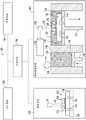
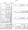
图1示意性地描绘了示例性增材制造系统;Figure 1 schematically depicts an exemplary additive manufacturing system;
图2示意性地描绘了示例性工作站;Figure 2 schematically depicts an exemplary workstation;
图3示意性地描绘了与图2中所描绘的工作站对应的示例性构建板;Figure 3 schematically depicts an exemplary build plate corresponding to the workstation depicted in Figure 2;
图4示意性地描绘了可由图2中所描绘的工作站包括的示例性锁销;FIG. 4 schematically depicts an exemplary locking pin that may be included by the workstation depicted in FIG. 2;
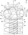
图5A-5C示意性地描绘了构建板-夹紧组件的方面,该构建板-夹紧组件可包括图2中所描绘的工作站和图3中所描绘的构建板;5A-5C schematically depict aspects of a build plate-clamping assembly that may include the workstation depicted in FIG. 2 and the build plate depicted in FIG. 3;
图6A示意性地描绘了包括固定到构建板的多个工件的示例性工件-组件;6A schematically depicts an exemplary workpiece-assembly including a plurality of workpieces secured to a build plate;
图6B示意性地描绘了图6A的示例性工件-组件,其中通过将延伸节段增材打印在固定到构建板的多个工件上而形成多个构件;6B schematically depicts the exemplary workpiece-assembly of FIG. 6A in which a plurality of components are formed by additively printing extension segments on a plurality of workpieces secured to a build plate;
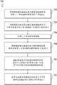
图7A示出了描绘将构建板与增材制造系统的坐标对准的示例性方法的流程图;7A shows a flowchart depicting an exemplary method of aligning a build plate with coordinates of an additive manufacturing system;
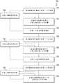
图7B示出了描绘在多个工作站处在工件上工作的示例性方法的流程图;7B shows a flowchart depicting an exemplary method of working on a workpiece at a plurality of workstations;
图7C示出了描绘将延伸节段增材打印在多个工件上的示例性方法的流程图;以及FIG. 7C shows a flowchart depicting an exemplary method of additively printing extended segments on a plurality of workpieces; and
图8示出了描绘增材制造系统的示例性控制系统的框图。8 shows a block diagram depicting an exemplary control system of an additive manufacturing system.
本说明书和附图中的参考字符的重复使用旨在表示本公开的相同或相似的特征或元件。Repeat use of reference characters in the present specification and drawings is intended to represent same or analogous features or elements of the present disclosure.
具体实施方式Detailed ways
现在将详细地参考目前公开的主题的示例性实施例,其一个或多个示例在附图中例示。各个示例通过阐释的方式来提供,并且不应当被解释为限制本公开。实际上,对于本领域技术人员而言将为明显的是,可在不脱离本公开的范围或精神的情况下在本公开中作出多种修改和变型。例如,作为一个实施例的部分而例示或描述的特征可与另一实施例一起使用以产生另外的其它实施例。因此,本公开旨在涵盖如归入所附权利要求书及其等同体的范围内的这样的修改和变型。Reference will now be made in detail to exemplary embodiments of the presently disclosed subject matter, one or more examples of which are illustrated in the accompanying drawings. The various examples are provided by way of illustration and should not be construed as limiting the present disclosure. In fact, it will be apparent to those skilled in the art that various modifications and variations can be made in the present disclosure without departing from the scope or spirit of the disclosure. For example, features illustrated or described as part of one embodiment can be used with another embodiment to yield yet another embodiment. Accordingly, the present disclosure is intended to cover such modifications and variations as come within the scope of the appended claims and their equivalents.
理解到,诸如“顶部”、“底部”、“向外”、“向内”等的用语是方便的词语,并且将不被解释为限制性的用语。如本文中所使用的,用语“第一”、“第二”和“第三”可能够互换地使用,以将一个构件与另一构件区分开,且不旨在表示单独构件的位置或重要性。用语“一”和“一种”不指示对量的限制,而是指示存在所引用的项中的至少一个。It is understood that terms such as "top," "bottom," "outward," "inward," etc. are words of convenience and should not be construed as terms of limitation. As used herein, the terms "first," "second," and "third" may be used interchangeably to distinguish one element from another, and are not intended to denote the position or location of individual elements or importance. The terms "a" and "an" do not denote a limitation of quantity, but rather denote the presence of at least one of the recited items.
在此并且在整个说明书和权利要求书中,范围限制组合且互换,并且,除非上下文或语言另外指示,否则这样的范围被标识,并且包括其中所包含的全部子范围。例如,本文中所公开的全部范围都包括端点,并且,端点能够彼此独立地组合。Here and throughout the specification and claims, range limitations are combined and interchanged, and unless context or language dictates otherwise, such ranges are identified and include all subranges subsumed therein. For example, all ranges disclosed herein are inclusive of the endpoints, and the endpoints are combinable independently of each other.
如本文中在整个说明书和权利要求书中使用的近似语言适用于修饰可容许变化的任何定量表示,而不会造成与其相关的基本功能的改变。因此,由诸如“大约”、“近似地”以及“基本上”的一个或多个用语修饰的值将不限于所规定的精确值。在至少一些情况下,近似语言可对应于用于测量该值的仪器的精度或用于构造或制造构件和/或系统的方法或机器的精度。Approximate language, as used herein throughout the specification and claims, is applied to modify any quantitative representation of permissible variation without causing a change in the basic function with which it is associated. Thus, a value modified by one or more terms such as "about," "approximately," and "substantially" is not to be limited to the precise value specified. In at least some cases, the approximation language may correspond to the precision of the instrument used to measure the value or the precision of the method or machine used to construct or manufacture the component and/or system.
如下文中详细地描述的,本主题的示例性实施例涉及增材制造机器或方法的使用。如本文中所使用的,用语“增材制造的”或“增材制造技术或过程”大体上指代如下的制造过程:其中(一种或多种)材料的连续层彼此上下地设置,以逐层地“建造”三维构件。连续层大体上熔合在一起以形成整体式构件,该整体式构件可具有多种一体的子构件。As described in detail below, exemplary embodiments of the present subject matter relate to the use of an additive manufacturing machine or method. As used herein, the term "additively manufactured" or "additive manufacturing technique or process" generally refers to a manufacturing process in which successive layers of material(s) are placed on top of each other to "Build" 3D components layer by layer. The successive layers are generally fused together to form a unitary member, which may have a variety of integral sub-members.
如本文中所使用的,用语“近净形”指代具有非常接近于最终“净”形的如打印的形状的增材打印的特征。近净形构件可经历表面精加工(诸如,抛光、磨光等),但不需要繁重的机加工以便实现最终“净”形。通过示例的方式,近净形与最终净形的差异可为大约1500微米或更小,诸如大约1000 µm或更小,诸如大约500 µm或更小,或诸如大约100 µm或更小,或诸如大约50 µm或更小,或诸如大约25 µm或更小。As used herein, the term "near net shape" refers to an additively printed feature having an as-printed shape that is very close to the final "net" shape. Near-net shape components can undergo surface finishing (such as polishing, buffing, etc.), but do not require heavy machining in order to achieve a final "net" shape. By way of example, the difference between near net shape and final net shape may be about 1500 microns or less, such as about 1000 μm or less, such as about 500 μm or less, or such as about 100 μm or less, or such as About 50 µm or less, or such as about 25 µm or less.
尽管本文中将增材制造工艺描述为通过典型地沿竖直方向逐点、逐层地构建物体来实现复杂物体的制备,但其它制备方法是可能的且处于本主题的范围内。例如,尽管本文中的论述涉及添加材料以形成连续层,但本领域技术人员将认识到,本文中所公开的方法和结构可与任何增材制造技术或制造工艺一起来实践。例如,本发明的实施例可使用层-增材过程、层-减材过程或混合过程。Although an additive manufacturing process is described herein as enabling the fabrication of complex objects by building the object point by point, layer by layer, typically in a vertical direction, other fabrication methods are possible and within the scope of the present subject matter. For example, although the discussion herein involves adding materials to form continuous layers, those skilled in the art will recognize that the methods and structures disclosed herein may be practiced with any additive manufacturing technique or manufacturing process. For example, embodiments of the present invention may use a layer-additive process, a layer-subtractive process, or a hybrid process.
根据本公开的合适的增材制造技术包括例如熔合沉积成型(FDM)、选择性激光烧结(SLS)、诸如通过喷墨和激光喷射(laserjet)的3D打印、立体光刻(SLA)、直接选择性激光烧结(DSLS)、电子束烧结(EBS)、电子束熔融(EBM)、激光工程化净成形(LENS)、激光净形制造(LNSM)、直接金属沉积(DMD)、数字光处理(DLP)、直接选择性激光熔融(DSLM)、选择性激光熔融(SLM)、直接金属激光熔融(DMLM)和其它已知的过程。Suitable additive manufacturing techniques according to the present disclosure include, for example, fusion deposition modeling (FDM), selective laser sintering (SLS), 3D printing such as by inkjet and laserjet, stereolithography (SLA), direct selection Laser Sintering (DSLS), Electron Beam Sintering (EBS), Electron Beam Melting (EBM), Laser Engineered Net Shaping (LENS), Laser Net Shape Manufacturing (LNSM), Direct Metal Deposition (DMD), Digital Light Processing (DLP) ), Direct Selective Laser Melting (DSLM), Selective Laser Melting (SLM), Direct Metal Laser Melting (DMLM) and other known processes.
除了使用直接金属激光烧结(DMLS)或直接金属激光熔融(DMLM)过程(其中使用能量源来选择性地使粉末层的部分烧结或熔融)之外,应当认识到,根据备选实施例,增材制造过程还可为“粘合剂喷射”过程。在这方面,粘合剂喷射涉及以与上文中所描述的方式类似的方式连续地沉积添加粉末层。然而,代替使用能量源来生成能量束以选择性地使添加粉末熔融或熔合,粘合剂喷射涉及选择性地将液体粘合剂沉积到各个粉末层上。液体粘合剂可为例如能够光固化的聚合物或另一液体结合剂。其它合适的增材制造方法和变体旨在处于本主题的范围内。In addition to using a direct metal laser sintering (DMLS) or direct metal laser melting (DMLM) process in which an energy source is used to selectively sinter or melt portions of the powder layer, it should be appreciated that, according to alternative embodiments, increased The material manufacturing process can also be a "binder jet" process. In this regard, binder jetting involves continuously depositing layers of additive powder in a manner similar to that described above. However, instead of using an energy source to generate an energy beam to selectively melt or fuse the additive powder, binder jetting involves selectively depositing a liquid binder onto individual powder layers. The liquid binder may be, for example, a photocurable polymer or another liquid binder. Other suitable additive manufacturing methods and variations are intended to be within the scope of the present subject matter.
本文中所描述的增材制造过程可用于使用任何合适的材料来形成构件。例如,材料可为塑料、金属、混凝土、陶瓷、聚合物、环氧树脂、光聚合物树脂,或可呈固体、液体、粉末、片材、线或任何其它合适形式的任何其它合适的材料。更具体地,根据本主题的示例性实施例,本文中所描述的增材制造的构件可部分地、完全地或以某一组合由包括但不限于下者的材料形成:纯金属、镍合金、铬合金、钛、钛合金、镁、镁合金、铝、铝合金、铁、铁合金、不锈钢和镍基或钴基超级合金(例如,能够以名称Inconel®(其能够从Special MetalsCorporation获得)获得的超级合金)。这些材料是适合于在本文中所描述的增材制造过程中使用的材料的示例,且大体上可被称为“添加材料”。The additive manufacturing process described herein can be used to form components using any suitable material. For example, the material can be plastic, metal, concrete, ceramic, polymer, epoxy, photopolymer resin, or any other suitable material that can be in solid, liquid, powder, sheet, wire, or any other suitable form. More specifically, according to exemplary embodiments of the present subject matter, the additively manufactured components described herein may be formed partially, completely, or in some combination from materials including, but not limited to: pure metals, nickel alloys , chromium alloys, titanium, titanium alloys, magnesium, magnesium alloys, aluminum, aluminum alloys, iron, iron alloys, stainless steel, and nickel- or cobalt-based superalloys (eg, available under the name Inconel® (available from Special Metals Corporation) super alloy). These materials are examples of materials suitable for use in the additive manufacturing processes described herein, and may generally be referred to as "additive materials."
另外,本领域技术人员将认识到,可使用用于结合那些材料的多种材料和方法且将其设想为处于本公开的范围内。如本文中所使用的,对“熔合”的引用可指代用于产生上文中的任何材料的结合层的任何合适的过程。例如,如果物体由聚合物制成,则熔合可指代在聚合物材料之间产生热固性结合。如果物体为环氧树脂,则结合可通过交联过程形成。如果材料为陶瓷,则结合可通过烧结过程形成。如果材料为粉末状金属,则结合可通过熔融或烧结过程形成。本领域技术人员将认识到,使材料熔合以通过增材制造来制作构件的其它方法是可能的,且目前公开的主题可与那些方法一起来实践。In addition, those skilled in the art will recognize that a variety of materials and methods for combining those materials may be used and are contemplated to be within the scope of the present disclosure. As used herein, reference to "fusion" may refer to any suitable process for producing a bonded layer of any of the materials above. For example, if the object is made of a polymer, fusing may refer to creating a thermoset bond between the polymer materials. If the object is an epoxy, the bond can be formed by a cross-linking process. If the material is ceramic, the bond can be formed by a sintering process. If the material is a powdered metal, the bond can be formed by a melting or sintering process. Those skilled in the art will recognize that other methods of fusing materials to make components by additive manufacturing are possible, and the presently disclosed subject matter can be practiced with those methods.
另外,本文中所公开的增材制造过程允许由多种材料形成单个构件。因此,本文中所描述的构件可由上文中的材料的任何合适的混合物形成。例如,构件可包括使用不同材料、过程和/或在不同增材制造机器上形成的多个层、节段或部分。以此方式,可构造具有不同的材料和材料性质以用于满足任何特定应用的需求的构件。另外,尽管本文中所描述的构件完全通过增材制造过程构造,但应当认识到,在备选实施例中,这些构件中的全部或部分可经由铸造、机加工和/或任何其它合适的制造过程而形成。实际上,可使用材料和制造方法的任何合适的组合来形成这些构件。Additionally, the additive manufacturing process disclosed herein allows for the formation of a single component from multiple materials. Accordingly, the components described herein may be formed from any suitable mixture of the above materials. For example, a component may include multiple layers, segments or sections formed using different materials, processes and/or on different additive manufacturing machines. In this manner, components with different materials and material properties can be constructed for meeting the needs of any particular application. Additionally, although the components described herein are constructed entirely through an additive manufacturing process, it should be appreciated that in alternative embodiments, all or a portion of these components may be fabricated via casting, machining, and/or any other suitable manufacturing process. process formed. In fact, any suitable combination of materials and fabrication methods may be used to form these components.
现在将描述示例性增材制造过程。增材制造过程使用构件的三维(3D)信息(例如,三维计算机模型)来制备构件。因此,可在制造之前限定构件的三维设计模型。在这方面,可扫描构件的模型或原型来确定构件的三维信息。作为另一示例,可使用合适的计算机辅助设计(CAD)程序来构造构件的模型,以限定构件的三维设计模型。An exemplary additive manufacturing process will now be described. The additive manufacturing process uses three-dimensional (3D) information of the component (eg, a three-dimensional computer model) to prepare the component. Thus, a three-dimensional design model of the component can be defined prior to fabrication. In this regard, a model or prototype of the component may be scanned to determine three-dimensional information for the component. As another example, a suitable computer-aided design (CAD) program may be used to construct a model of the component to define a three-dimensional design model of the component.
设计模型可包括构件的整个构造(包括构件的外部表面和内部表面两者)的3D数字坐标。例如,设计模型可限定主体、表面和/或内部通路,诸如开口、支承结构等。在一个示例性实施例中,三维设计模型转换成例如沿着构件的中心(例如,竖直)轴线或任何其它合适的轴线的多个切片或节段。各个切片可针对切片的预先确定的高度而限定构件的薄横截面。多个连续横截面切片一起形成3D构件。然后逐个切片或逐层地“建造”构件,直到完成。The design model may include 3D numerical coordinates of the entire configuration of the component, including both the exterior and interior surfaces of the component. For example, the design model may define bodies, surfaces, and/or internal passages, such as openings, support structures, and the like. In one exemplary embodiment, the three-dimensional design model is converted into a plurality of slices or segments, eg, along a central (eg, vertical) axis of the component or any other suitable axis. Each slice may define a thin cross-section of the member for a predetermined height of the slice. Multiple consecutive cross-sectional slices together form a 3D component. Components are then "built" slice by slice or layer by layer until complete.
以此方式,可使用增材过程来制备本文中所描述的构件,或更具体地,例如通过使用激光能量或热使塑料熔合或聚合或通过使金属粉末烧结或熔融而连续地形成各个层。例如,特定类型的增材制造过程可使用能量束(例如,电子束或电磁辐射,诸如激光束)来使粉末材料烧结或熔融。可使用任何合适的激光和激光参数,包括相对于功率、激光束光点尺寸和扫描速率的考虑。构建材料可由针对增强的强度、耐用性和使用寿命(特别是在高温下)而选择的任何合适的粉末或材料形成。In this way, an additive process can be used to produce the components described herein, or more specifically, the layers are continuously formed, for example, by fusing or polymerizing plastics using laser energy or heat, or by sintering or melting metal powders. For example, certain types of additive manufacturing processes may use energy beams (eg, electron beams or electromagnetic radiation, such as laser beams) to sinter or melt powder materials. Any suitable laser and laser parameters may be used, including considerations relative to power, laser beam spot size, and scan rate. The build material may be formed from any suitable powder or material selected for enhanced strength, durability, and longevity, especially at elevated temperatures.
各个连续层例如可在大约10 µm与200 µm之间,但根据备选实施例,厚度可基于任何数量的参数来选择,且可为任何合适的尺寸。因此,通过利用上文中所描述的增材成形方法,本文中所描述的构件可具有与在增材成形过程期间利用的相关联的粉末层的一个厚度(例如,10 µm)一样薄的横截面。Each successive layer may be, for example, between about 10 μm and 200 μm, but according to alternative embodiments, the thickness may be selected based on any number of parameters, and may be of any suitable size. Thus, by utilizing the additive forming method described above, the components described herein can have a cross-section as thin as one thickness (eg, 10 μm) of the associated powder layer utilized during the additive forming process .
另外,通过利用增材过程,构件的表面光洁度和特征可取决于应用而如需要的那样变化。例如,可通过在增材过程期间选择适当的激光扫描参数(例如,激光功率、扫描速度、激光焦点尺寸等)(尤其是在横截面层的与零件表面对应的外围中)来调整表面光洁度(例如,使其较光滑或较粗糙)。例如,可通过增大激光扫描速度或减小形成的熔融池的尺寸来实现较粗糙的光洁度,且可通过减小激光扫描速度或增大形成的熔融池的尺寸来实现较光滑的光洁度。还可改变扫描图案和/或激光功率以改变所选择的区域中的表面光洁度。Additionally, by utilizing an additive process, the surface finish and characteristics of the component can vary as desired depending on the application. For example, the surface finish can be adjusted by selecting appropriate laser scanning parameters (eg, laser power, scanning speed, laser focus size, etc.) during the additive process (especially in the periphery of the cross-sectional layer corresponding to the part surface). For example, make it smoother or rougher). For example, a rougher finish can be achieved by increasing the laser scanning speed or reducing the size of the molten pool formed, and a smoother finish can be achieved by reducing the laser scanning speed or increasing the size of the molten pool formed. The scan pattern and/or laser power can also be varied to vary the surface finish in selected areas.
在完成构件的制备之后,可将多种后处理程序应用于构件。例如,后处理程序可包括通过例如吹扫或抽真空来移除多余的粉末。其它后处理程序可包括应力解除过程。另外,可使用热、机械和/或化学后处理程序来对零件进行精加工,以实现期望的强度、表面光洁度和其它构件性质或特征。After the preparation of the component is complete, various post-processing procedures can be applied to the component. For example, post-processing procedures may include removal of excess powder by, for example, purging or vacuuming. Other post-processing procedures may include stress relief procedures. Additionally, thermal, mechanical, and/or chemical post-processing procedures may be used to finish the part to achieve desired strength, surface finish, and other component properties or characteristics.
值得注意地,在示例性实施例中,由于制造限制,本主题的若干方面和特征先前是不可能的。然而,本发明人已有利地利用增材制造技术中的当前进展来改进增材制造这样的构件的多种构件和方法。虽然本公开不限于使用增材制造来大体上形成这些构件,但增材制造确实提供了多种制造优点,包括制造的简易性、降低的成本、较高的准确度等。Notably, in exemplary embodiments, several aspects and features of the present subject matter were previously not possible due to manufacturing limitations. However, the present inventors have advantageously taken advantage of current advances in additive manufacturing technology to improve various components and methods of additively manufacturing such components. While the present disclosure is not limited to the use of additive manufacturing to form these components in general, additive manufacturing does provide a variety of manufacturing advantages, including ease of manufacture, reduced cost, higher accuracy, and the like.
并且,上文中所描述的增材制造方法实现以非常高的精度水平形成本文中所描述的构件的复杂得多且错综得多的形状和轮廓。例如,这样的构件可包括薄的增材制造层、横截面特征和构件轮廓。另外,增材制造过程实现具有不同材料的单个构件的制造,使得构件的不同部分可表现出不同的性能特性。制造过程的连续、增材本质实现这些新颖特征的构造。结果,使用本文中所描述的方法来形成的构件可表现出改进的性能和可靠性。Also, the additive manufacturing method described above enables the formation of the much more complex and intricate shapes and contours of the components described herein with a very high level of precision. For example, such components may include thin additively manufactured layers, cross-sectional features, and component profiles. In addition, the additive manufacturing process enables the manufacture of individual components with different materials, so that different parts of the component can exhibit different performance characteristics. The continuous, additive nature of the manufacturing process enables the construction of these novel features. As a result, components formed using the methods described herein can exhibit improved performance and reliability.
本公开大体上提供了构造成在预先存在的工件上增材打印的增材制造机器、系统以及方法。预先存在的工件可包括新的工件以及正在修复、再构建或升级的工件。在一个方面,提供了构建板-夹紧组件,其可构造成以高的精度和准确度等级将构建板与增材制造系统的坐标对准。目前公开的构建板可包括插座,该插座构造成以被选择成允许在增材制造过程期间热膨胀同时仍然提供高度精确并准确的锁定接合的公差配合在插座-接纳凹部内。例如,通过使用目前公开的构建板-夹紧组件,构建板可在从大约10微米至大约50微米(诸如从大约20 µm至大约30 µm,诸如大约50 µm或更小,诸如大约35 µm或更小,诸如大约25 µm或更小,或诸如大约15 µm或更小)的公差内与工作站锁定地接合。The present disclosure generally provides additive manufacturing machines, systems, and methods configured to additively print on pre-existing workpieces. Pre-existing artifacts can include new artifacts as well as artifacts that are being repaired, rebuilt, or upgraded. In one aspect, a build plate-clamping assembly is provided that can be configured to align the build plate with the coordinates of an additive manufacturing system with a high level of precision and accuracy. The presently disclosed build plate may include a socket configured to fit within the socket-receiving recess with a tolerance selected to allow thermal expansion during the additive manufacturing process while still providing a highly precise and accurate locking engagement. For example, by using the presently disclosed build plate-clamp assembly, the build plate can be made at from about 10 microns to about 50 microns (such as from about 20 μm to about 30 μm, such as about 50 μm or less, such as about 35 μm or smaller, such as about 25 μm or less, or such as about 15 μm or less) lockingly engages with the workstation.
示例性构建板-夹紧组件可包括从工作站的构建板-接纳表面伸出的一个或多个锁销。一个或多个锁销可包括诸如止动球的一个或多个止动件,其可为能够沿径向伸出的,以便与构建板的一个或多个插座锁定地接合。锁销可被气动促动,以便允许将构建板与构建板-接纳表面快速地接合和脱离。备选地,可使用任何合乎期望的原动力(包括诸如压电开关的电促动器或诸如固定螺钉的人工促动器)来促动锁销。An exemplary build plate-clamp assembly may include one or more locking pins extending from a build plate-receiving surface of the workstation. The one or more locking pins may include one or more detents, such as detent balls, which may be radially extendable for locking engagement with one or more receptacles of the build plate. The locking pin may be pneumatically actuated to allow rapid engagement and disengagement of the build plate with the build plate-receiving surface. Alternatively, any desired motive force may be used to actuate the locking pin, including an electrical actuator such as a piezoelectric switch or a manual actuator such as a set screw.
锁销可以以足够的准确度和精度与构建板的对应的插座锁定地接合,以便将构建板和/或固定到构建板的一个或多个工件与增材制造系统的坐标(包括视觉系统的坐标和/或增材制造机器的坐标)对准。在构建板和/或一个或多个工件与这样的坐标对准的情况下,视觉系统和增材制造机器可彼此协同地工作,从而使用视觉系统来获得工件的数字表示,并且使用增材制造机器来根据基于从视觉系统获得的工件的数字表示生成的打印命令而将延伸节段增材打印在工件上。例如,数字表示可包括工件的相应的工件-界面,并且打印命令可配置成使增材制造机器将延伸节段增材打印在工件-界面上,以便提供近净形构件。The locking pins may lockingly engage corresponding sockets of the build plate with sufficient accuracy and precision to connect the build plate and/or one or more workpieces secured to the build plate with the coordinates of the additive manufacturing system (including the vision system's coordinates and/or of the additive manufacturing machine) alignment. With the build plate and/or one or more workpieces aligned with such coordinates, the vision system and the additive manufacturing machine can work in conjunction with each other to use the vision system to obtain a digital representation of the workpiece, and use additive manufacturing The machine additively prints the extension segments on the workpiece according to print orders generated based on the digital representation of the workpiece obtained from the vision system. For example, the digital representation may include a corresponding workpiece-interface of the workpiece, and the print command may be configured to cause the additive manufacturing machine to additively print an extension segment on the workpiece-interface to provide a near-net-shape feature.
目前公开的锁销可包括冲洗通道,该冲洗通道构造成允许流体诸如通过一个或多个锁销孔口和/或一个或多个冲洗孔口而从锁销冲洗诸如粉末的碎屑。冲洗通道提供锁销的自清洁,以便避免来自增材制造系统的粉末干涉锁销的操作或使构成构建板-夹紧组件的多种构件过早地磨损或损伤。The presently disclosed latch may include a flush channel configured to allow a fluid to flush debris, such as powder, from the latch, such as through one or more latch apertures and/or one or more flush apertures. The flush channel provides self-cleaning of the locking pin in order to avoid powder from the additive manufacturing system interfering with the operation of the locking pin or causing premature wear or damage to the various components that make up the build plate-clamp assembly.
本文中所描述的目前公开的构建板-夹紧组件、系统和方法允许同时地或并行地在多个工件的工件-界面上增材打印来作为同一次构建的部分。在其它优点中,这样的构建板-夹紧组件可在再构建工件时提供提高的生产率和减少的所消耗的劳动和时间。另外,当将延伸节段增材打印在多个工件上时,构建板和/或一个或多个工件与增材制造系统坐标的对准促进近净形构件的产生。The presently disclosed build plate-clamping assemblies, systems and methods described herein allow for additive printing of workpiece-interfaces of multiple workpieces simultaneously or in parallel as part of the same build. Among other advantages, such a build plate-clamp assembly can provide increased productivity and reduced labor and time consumed when rebuilding workpieces. Additionally, when the extension segments are additively printed on multiple workpieces, the alignment of the build plate and/or one or more workpieces with the coordinates of the additive manufacturing system facilitates the creation of near-net-shape components.
图1中示出了增材制造系统100的示例性实施例。示例性增材制造系统100包括视觉系统102、增材制造机器104以及控制系统106,控制系统106能够操作地配置成控制视觉系统102和/或增材制造机器104。视觉系统102和增材制造机器104可作为单个集成式单元或作为分开的独立式单元来提供。视觉系统102和增材制造机器104可经由通信接口来彼此能够操作地耦合,该通信接口利用可提供视觉系统102与增材制造机器104之间的直接连接的有线或无线通信线路。控制系统106可包括一个或多个控制系统106。例如,单个控制系统106可能够操作地配置成控制视觉系统102和增材制造机器104的操作,或分开的控制系统106可能够操作地配置成分别控制视觉系统102和增材制造机器104。控制系统106可实现为视觉系统102的部分、增材制造机器104的部分和/或与视觉系统102和/或增材制造机器104分开来提供的独立式单元。控制系统106可经由通信接口来与视觉系统102和/或增材制造机器104能够操作地耦合,该通信接口利用可提供控制系统106与视觉系统102之间和/或控制系统106与增材制造机器104之间的直接连接的有线或无线通信线路。示例性增材制造系统100可任选地包括用户界面108和/或管理系统110。An exemplary embodiment of an
在一些实施例中,第一控制系统106可生成一个或多个打印命令,且/或将一个或多个打印命令传送到第二控制系统106,并且,第二控制系统106可使增材制造机器104至少部分地基于打印命令而增材打印延伸节段。第一控制系统106可实现为视觉系统102的部分,且/或第二控制系统106可实现为增材制造机器104的部分。备选地或另外,第一控制系统106和/或第二控制系统106可实现为与视觉系统102和/或增材制造机器104分开的独立式单元。In some embodiments, the
视觉系统102可包括可能够操作地配置成获得包括一个或多个视场114的数字表示的图像数据的任何合适的一个或多个相机112或其它机器视觉装置。这样的数字表示有时可被称为数字图像或被称为图像;然而,将认识到,可在不以人类可见的形式呈现这样的数字表示的情况下实践本公开。尽管如此,在一些实施例中,对应于视场114的人类可见的图像还是可至少部分地基于一个或多个视场114的这样的数字表示而显示于用户界面108上。
视觉系统102允许增材制造系统100获得与一个或多个工件116有关的信息,一个或多个延伸节段可分别被增材打印到一个或多个工件116上。特别地,视觉系统102允许将一个或多个工件116定位并且限定成使得可指示增材制造机器104以适当地高的准确度和精度将一个或多个延伸节段打印在对应的一个或多个工件116上。一个或多个工件116可在相应的工件116的工件-界面(例如,顶表面)120与构建平面122对准的情况下固定到构建板118。构建板118可利用一个或多个视觉系统-锁销126来固定到视觉系统-工作站124。一个或多个视觉系统-锁销126可根据本公开来构造,以便以足够高的准确度和精度将构建板118定位在视觉系统-工作站124上。
视觉系统102的一个或多个相机112可配置成获得二维或三维图像数据(包括视场114的二维数字表示和/或视场114的三维数字表示)。工件-界面120与构建平面122的对准允许一个或多个相机112获得较高质量的图像。例如,一个或多个相机112可具有调整或能够调整到构建平面122的焦距。在一个或多个工件116的工件-界面120与构建平面122对准的情况下,一个或多个相机可容易地获得工件-界面120的数字图像。一个或多个相机112可包括包含固定到构建板118的一个或多个工件116中的全部或部分的视场114。例如,单个视场114可宽到足以包含多个工件116(诸如,固定到构建板118的多个工件中的各个)。备选地,视场114可较窄地聚焦于单独的工件116上,使得分开获得相应的工件116的数字表示。将认识到,可将分开获得的数字图像拼接(stitch)在一起,以获得多个工件116的数字表示。在一些实施例中,相机112可包括准直透镜,准直透镜配置成提供平坦的焦平面,使得朝向视场114的外围定位的工件或其部分未畸变。另外或在备选方案中,视觉系统102可利用畸变校正算法来解决任何这样的畸变。One or
由视觉系统102获得的图像数据(包括一个或多个工件116的数字表示)可被传送到控制系统106。控制系统106可配置成根据已由视觉系统102捕获的一个或多个视场114的一个或多个数字表示来确定多个工件116中的各个的工件-界面120,并且然后确定多个工件116中的相应的工件116的工件-界面120的一个或多个坐标。基于一个或多个数字表示,控制系统106可生成一个或多个打印命令,一个或多个打印命令可被传送到增材制造机器104,使得增材制造机器104可将多个延伸节段增材打印在多个工件116中的相应的工件116上。一个或多个打印命令可配置成增材打印多个延伸节段,其中多个延伸节段中的各个相应的延伸节段定位在对应的工件116的工件-界面120上。Image data (including digital representations of one or more workpieces 116 ) obtained by
增材制造机器104可利用任何期望的增材制造工艺。在示例性实施例中,增材制造机器可利用粉末床熔合(PBF)工艺,诸如直接金属激光熔融(DMLM)、电子束熔融(EBM)、选择性激光熔融(SLM)、定向金属激光烧结(DMLS)或选择性激光烧结(SLS)。增材制造机器104可包括任何这样的增材制造工艺,或还可使用任何其它合适的增材制造工艺。通过示例的方式,可使用粉末床熔合工艺来通过使粉末材料层熔融或熔合到工件-界面120而将多个延伸节段中的相应的延伸节段以逐层的方式增材打印在多个工件116中的对应的相应的工件116上。在一些实施例中,可通过使粉末状材料的单层熔融或熔合到工件-界面120而增材打印构件。另外或在备选方案中,随后的粉末材料层可顺序地彼此熔融或熔合。The
仍然参考图1,示例性增材制造机器104包括构建室132和容纳成批的粉末130的粉末供应室128。具有固定到其的一个或多个工件116的构建板118可定位在构建室132中,在构建室132中,可以以逐层的方式增材打印工件116。粉末供应室128包括粉末活塞134,其在系统100的操作期间提升粉末底面136。当粉末底面136提升时,粉末130的部分被迫离开粉末供应室128。Still referring to FIG. 1 , the example
诸如辊子或刀片的再涂覆器138将粉末130中的一些推过工作表面140并推到增材制造-工作站142上。构建板118可利用一个或多个增材制造机器-锁销144来固定到增材制造-工作站142。一个或多个增材制造机器-锁销144可根据本公开来构造,以便以足够高的准确度和精度将构建板118定位在增材制造-工作站142上和/或构建室132内。工件116可在将构建板118固定到增材制造-工作站142之前固定到构建板118。再涂覆器138利用粉末130来填充构建室132,且然后在工件116的顶部附近顺序地将粉末130的薄层分配在整个构建平面122上,以增材打印工件116的顺序层。例如,粉末130的薄层可为大约10至100微米厚,诸如大约20至80 µm厚,诸如大约40至60 µm厚,或诸如大约20至50 µm厚,或诸如大约10至30 µm厚。构建平面122表示与将由粉末130形成的工件116的下一层对应的平面。A
为了在工件116(例如,界面层或随后的层)上形成延伸节段的层,能量源146将诸如激光或电子束的能量束148沿着构建平面122引导至粉末130的薄层上,以使粉末130熔融或熔合到工件116的顶部(例如,使层熔融或熔合到工件-界面120且/或使随后的层熔融或熔合到该层)。扫描器150控制束的路径,以便仅使粉末130层的将变成熔融或熔合到工件116的部分熔融或熔合。典型地,利用DMLM、EBM或SLM系统来使粉末130完全地熔融,其中相应的层利用能量束148的相应的经过来熔融或再熔融。相反地,利用DMLS或SLS系统来使粉末130的层烧结,从而大体上在未达到粉末130的熔点的情况下使粉末130的颗粒彼此熔合。在粉末130的层熔融或熔合到工件116之后,构建活塞152使增材制造-工作站142以一定的增量逐渐地下降,从而针对粉末130的下一层和再涂覆器138而限定下一个构建平面122,以将粉末130的下一层分配在整个构建平面122上。粉末130的顺序层可以以此方式熔融或熔合到工件116,直到完成增材打印过程。To form a layer of extended segments on workpiece 116 (eg, an interface layer or a subsequent layer),
现在参考图2和图3,将描述示例性构建板-夹紧组件。示例性构建板-夹紧组件包括工作站200,诸如图2中所示出的工作站。示例性构建板-夹紧组件可另外包括诸如图3中所示出的与工作站对应的构建板118。图2中所示出的工作站200可描绘视觉系统-工作站124和/或增材制造-工作站142。如图2中所示出的,示例性工作站200包括构建板-接纳表面202和从工作站200的构建板-接纳表面202伸出的一个或多个锁销204。一个或多个锁销204包括能够从相应的锁销204沿径向伸出的一个或多个止动件206,诸如止动球或其它锁定元件。包括止动件206的一个或多个锁销204的使用有利地允许构建板118固定到构建板-接纳表面202,同时还允许构建板118相对于构建板-接纳表面202侧向地、竖直地且旋转地对准。Referring now to Figures 2 and 3, an exemplary build plate-clamp assembly will be described. An exemplary build plate-clamping assembly includes a
虽然在图2中示出了两个锁销204,但将认识到,所描绘的实施例通过示例的方式来提供,且将并非限制性的。实际上,在不脱离本公开的精神和范围的情况下,可提供任何期望数量的锁销204,诸如,例如至少一个锁销204、至少两个锁销204、至少三个锁销204或至少四个锁销204。另外,虽然图2中所描绘的锁销包括多个止动件206,但将认识到,所描绘的止动件206的数量通过示例的方式来提供,且将并非限制性的。在不脱离本公开的精神和范围的情况下,锁销204的多种实施例可包括任何期望数量的止动件206,包括例如至少一个止动件206、至少两个止动件206、至少三个止动件206或至少四个止动件206。While two locking
例如,锁销204的数量和/或止动件206的数量可被选择成增加构建板118固定到构建板的压紧力(hold-down)或安全性。除了锁销204之外,构建板-接纳表面202还可包括可有助于将构建板118与构建板-接纳表面202对准的其它特征,诸如凹槽、凹口、脊、销、凹部等,其可构造成与构建板118的对应特征匹配。这样的其它特征可构造成提供构建板118与构建板-接纳表面202的竖直、侧向和/或旋转对准。For example, the number of locking
现在参考图3,将描述示例性构建板118的多种方面。构建板118可包括与工作站200的构建板-接纳表面202对应的一个或多个特征,以便允许构建板118至少部分地由一个或多个锁销204夹紧到工作站200。如图3中所示出的,示例性构建板118包括一个或多个插座300,其围绕构建板118而构造并布置,以便与工作站200的一个或多个锁销204对应。插座300可限定构建板118的一体的无缝部分。备选地,如所示出的,插座300可诸如以干涉配合安装在构建板中的插座-接纳凹部302中。干涉配合可定尺寸成以便允许插座300以被选择成允许在增材制造过程期间热膨胀的公差在插座-接纳凹部302内浮动。在备选实施例中,插座300可固定到构建板118,并且可允许锁销204浮动,例如,以便类似地允许在增材制造过程期间热膨胀。Referring now to FIG. 3, various aspects of the
不管插座300是限定构建板118的一体的无缝部分还是安装在插座-接纳凹部302中,插座300都可包括限定接合表面的内表面304,该接合表面构造成允许锁销与插座300锁定地接合。接合表面可延伸跨过插座300的内表面302的全部或部分,并延伸通过构建板118的部分或完全通过构建板118。Regardless of whether the
在一些实施例中,接合表面可包括与止动件206中的相应的止动件206对应的一个或多个凹部,以便提供构建板118与构建板-接纳表面202的旋转对准。以此方式,单个锁销204可提供构建板118与构建板-接纳表面202的侧向对准和旋转对准两者。In some embodiments, the engagement surfaces may include one or more recesses corresponding to corresponding ones of the
在一些实施例中,多种不同构造的插座300可能够互换地安装在插座-接纳凹部302中。例如,可提供不同构造的插座300,以便适应不同构造的锁销204。虽然在图3中示出了两个插座300,但将认识到,所描绘的实施例通过示例的方式来提供,且将并非限制性的。实际上,在不脱离本公开的精神和范围的情况下,可提供任何期望数量的插座300,诸如,例如至少一个插座300、至少两个插座300、至少三个插座300或至少四个插座300。然而,插座300的数量典型地将在数量上至少与在工作站200的构建板-接纳表面202上提供的锁销204的数量对应。然而,在一些实施例中,插座300的数量可超过在工作站200的构建板-接纳表面202上提供的锁销204的数量。在一些实施例中,多个构建板-接纳表面202可限定在工作站200上,使得工作站200可接纳多个构建板118,且/或使得工作站200可接纳多种不同的构建板118,诸如在插座300的数量和/或构造方面不同的构建板118。In some embodiments, a variety of differently configured
仍然参考图3,在一些实施例中,当插座300安装在插座-接纳凹部302中时,构建板118可另外包括与插座-接纳凹部302相交的一个或多个插座螺栓-接纳孔306。一个或多个插座螺栓-接纳孔306可构造成接纳插座锁定螺栓308,并且诸如插座锁定螺栓308可诸如通过螺纹配合和/或干涉配合而能够插入插座螺栓-接纳孔306中。插座300可至少部分地通过已插入到对应的插座螺栓-接纳孔306中的一个或多个插座螺栓308而能够与构建板118(例如,与插座-接纳凹部302)锁定地接合。例如,插座300的外表面可包括围绕插座300的外表面的至少部分而设置的插座螺栓-接合通道310。插座螺栓-接合通道310的位置可被选择成与和插座-接纳凹部302相交的插座螺栓-接纳孔306对准,使得插座锁定螺栓308可与插座螺栓-接合通道310锁定地接合。Still referring to FIG. 3 , in some embodiments, the
在示例性实施例中,构建板118可包括与插座-接纳凹部302的第一侧相交的第一插座螺栓-接纳孔306和与插座-接纳凹部302的第二侧相交的第二插座螺栓-接纳孔306。第一插座螺栓-接纳孔306可构造成接纳能够插入其中的第一插座锁定螺栓308,并且第二插座螺栓-接纳孔306可构造成接纳能够插入其中的第二插座锁定螺栓308。第一插座螺栓-接纳孔306和第二插座螺栓-接纳孔306可与插座300的外表面上的插座螺栓-接合通道310对准。插座300可至少部分地通过第一插座锁定螺栓308和/或第二插座锁定螺栓308而能够与构建板118锁定地接合,第一插座锁定螺栓308已插入到第一插座螺栓-接纳孔306中并与插座螺栓-接合通道310接合,第二插座锁定螺栓308已插入到第二插座螺栓-接纳孔306中并与插座螺栓-接合通道310接合。In an exemplary embodiment, the
现在参考图4,将描述示例性锁销204的另外的方面。如所示出的,示例性锁销204可包括中空销主体400、活塞402,活塞402设置在中空销主体400内,诸如在构造并布置成接纳活塞402的轴向活塞通路404内。活塞402可能够沿轴向移动,以便促动和缩回一个或多个止动件206。活塞402可能够从沿轴向远离一个或多个止动件206而定位的缩回位置沿轴向移动到沿轴向靠近于一个或多个止动件206而定位的促动位置。一个或多个止动件206可能够响应于活塞402已沿轴向移动到促动位置而从相应的锁销204通过中空销主体400中的对应的止动件-孔口406沿径向伸出。活塞402可能够通过任何期望的手段促动,包括能够由机械杠杆等促动的机械活塞402、能够由气动流体促动的气动活塞402、能够由液压流体促动的液压活塞402、能够由诸如电磁体的磁源促动的磁性活塞402等。Referring now to FIG. 4, additional aspects of the
在一些实施例中,锁销204可包括在活塞402与一个或多个止动件206之间设置在中空销主体400内的楔入元件408。一个或多个楔入元件408可具有倾斜或弯曲的表面,该表面将活塞402的轴向移动410能够滑动地转换成一个或多个止动件206的径向移动(例如,径向伸出和/或径向缩回)412。例如,一个或多个楔入元件408可响应于活塞402已沿轴向移动到促动位置而使一个或多个止动件206沿径向伸出。In some embodiments, the locking
一个或多个止动件206可具有适合于响应于楔入元件408的能够滑动地转换的移动而通过径向移动412从止动件-孔口406沿径向伸出的任何期望的形状。一个或多个楔入元件408可具有提供适当地倾斜或弯曲的表面的任何期望的形状,该表面将活塞402的轴向移动410能够滑动地转换成一个或多个止动件206的径向移动412。如图4中所示出的,止动件206和楔入元件408两者都具有球形形状。然而,将认识到,止动件206和/或楔入元件408可根据其它合适的形状(包括截头圆锥形状和多面体形状)来构造。在一些实施例中,楔入元件408可为活塞402的组成部分,或者可省略楔入元件408,并且活塞402可将轴向移动410能够滑动地转换成一个或多个止动件206的径向移动412。然而,球形形状的止动件206和球形形状的楔入元件408可为合乎期望的,以便减小一个或多个止动件206和/或一个或多个楔入元件408之间的摩擦,并允许一个或多个止动件206和/或一个或多个楔入元件408在中空销主体400内、抵靠止动件-孔口406和/或抵靠插座300的接合表面而自由地旋转。One or
止动件-孔口406可提供具有足够尺寸的开口,以允许止动件206部分地通过该开口而沿径向伸出,使得止动件206可与接合表面锁定地接合。止动件-孔口406的横截面宽度可小于止动件206的横截面宽度,以便防止止动件206从止动件-孔口406中掉出。The stopper-
现在参考图5A-5C,将描述构建板-夹紧组件500的另外的方面。如图5A-5C中所示出的,示例性构建板-夹紧组件500可包括具有构建板-接纳表面202的工作站200,以及从工作站200的构建板-接纳表面202伸出的一个或多个锁销204。一个或多个锁销204可包括中空销主体400、设置在中空销主体400内的活塞402。活塞能够从缩回位置502沿轴向移动到促动位置504,使得活塞402可促动一个或多个锁销204中的相应的锁销204的一个或多个止动件206。一个或多个止动件206可能够响应于活塞402已沿轴向移动到促动位置504而通过中空销主体400中的多个止动件-孔口406中的相应的止动件-孔口406沿径向伸出。Referring now to Figures 5A-5C, additional aspects of the build plate-
构建板-夹紧组件500可另外包括构建板118,构建板118构造成至少部分地由一个或多个锁销204夹紧到工作站200。构建板118可包括一个或多个插座300,插座300具有内表面304,内表面304限定用于一个或多个止动件206的接合表面506,以将一个或多个锁销204中的相应的一个锁销204与一个或多个插座300中的对应的一个插座300锁定地接合。在一些实施例中,接合表面506可包括构造成锁定地接合一个或多个止动件206的底切、凹口、凹槽、倒角等。The build plate-
为了将构建板118与工作站200的构建板-接纳表面202锁定地接合,构建板118可定位到构建板-接纳表面202上,其中一个或多个锁销204配合到对应的插座300中。构建板-夹紧组件500可包括流体系统508,流体系统508构造成促动一个或多个锁销204。流体系统可包括流体源510,流体源510可包括流体贮存器、泵和/或压缩机。流体源510可容纳流体512,诸如气动流体或液压流体。锁销204的活塞402可能够由流体512促动,流体512可被供应到活塞402的远端,活塞402的远端可经由一个或多个活塞流体供应管线514而与流体源510成流体连通。在一些实施例中,流体供应阀516可定位在一个或多个流体供应管线处。流体供应阀516可能够移动到打开位置以促动活塞402,从而将活塞移动到促动位置504,并且流体供应阀516可能够移动到关闭位置以缩回活塞,从而将活塞移动到缩回位置502。To lockingly engage the
流体源510还可诸如经由一个或多个冲洗流体供应管线518而向冲洗通道414供应流体512。任选地,冲洗流体供应阀520可定位在一个或多个流体供应管线518处,以便启动和停止流向冲洗通道414的流体512的流。在一些实施例中,一个或多个冲洗流体供应管线518的至少部分可限定通过锁销204的中空销主体400的通路。当活塞402移动到缩回位置502时和/或当活塞402移动到促动位置504时,冲洗通道414和冲洗流体供应管线518的通过中空销主体400的通路可构造成彼此对准并由此流体连通。在一些实施例中,当活塞402移动到缩回位置502时,可建立冲洗通道414与冲洗流体供应管线518之间的流体连通,使得当活塞402移动到缩回位置502时,可从锁销204冲洗碎屑。例如,当从工作站200移除构建板118时,可启动通过冲洗通道414的流体512流。以此方式,当移除构建板118时,流过冲洗通道414的流体512可防止诸如粉末130的碎屑掉入锁销204中,且/或流体512可从锁销204冲洗任何这样的碎屑,否则这些碎屑可积聚在锁销204中和/或锁销204的周围。
图5B示出了与工作站200的构建板-接纳表面202锁定地接合的构建板118。流体供应阀516处于打开位置,从而允许流体512将多个活塞402移动到促动位置504。活塞402移动在活塞与多个止动件206之间设置在锁销204的中空销主体400内的相应的楔入元件408。楔入元件408包括倾斜或弯曲的表面,该表面构造成允许楔入元件408响应于活塞402已沿轴向移动到促动位置504而将活塞402的轴向移动410能够滑动地转换成多个止动件206的径向伸出。多个止动件206从对应的止动件-孔口406沿径向伸出,由此与对应于相应的锁销204的插座300的接合表面506锁定地接合。可利用任何合适的活塞402,包括弹簧作用活塞402、弹簧复位活塞402和/或弹簧伸出活塞402。在示例性实施例中,活塞402可为弹簧伸出活塞402,其有利地防止活塞402在空气压力损失的情况下缩回。FIG. 5B shows the
图5C示出了位于工作站200的构建板-接纳表面202上的构建板118,其中流体供应阀516处于关闭位置,从而允许多个活塞402移动到缩回位置502。在活塞402移动到缩回位置502的情况下,楔入元件408和止动件206可缩回到活塞402的中空主体中,由此使止动件206从对应于相应的锁销204的插座300的接合表面506脱离。在止动件206从接合表面506脱离的情况下,可从构建板-接纳表面202移除构建板118。FIG. 5C shows the
再次参考图4,在一些实施例中,锁销204可包括冲洗通道414,冲洗通道414限定用于使流体512从流体源510流动并从中空销主体400排出以便从锁销204冲洗碎屑的通路。冲洗通道414可形成在活塞402和/或锁销204的中空销主体400内。在一些实施例中,冲洗通道414可沿着活塞402螺旋地横过,且/或冲洗通道414可沿着中空活塞主体400的内表面螺旋地横过。虽然示出了单个冲洗通道414,但将认识到,在不脱离本公开的精神和范围的情况下,可提供任何数量的冲洗通道414,诸如至少一个冲洗通道、至少两个冲洗通道等。Referring again to FIG. 4 , in some embodiments, the locking
一个或多个冲洗通道414可与多个止动件-孔口406成流体连通,以便允许流体512通过多个止动件-孔口406而从锁销204冲洗诸如粉末130的碎屑。另外或在备选方案中,锁销204可包括围绕中空销主体400而设置的一个或多个冲洗孔口416。一个或多个冲洗孔口416可与一个或多个冲洗通道414成流体连通,以便允许流体512从锁销204冲洗诸如粉末130的碎屑。示例性冲洗通路418可通过设置在中空销主体400的近端420处的一个或多个冲洗孔口416排出。另一示例性冲洗通路422可另外或备选地通过围绕多个止动件-孔口406中的至少一个而设置的多个冲洗孔口416排出。可在将构建板118锁定地接合在工作站200处之前、期间和/或之后(例如,在多个止动件206已将锁销204与插座300锁定地接合之前、期间和/或之后)利用冲洗通道414。One or more
现在参考图6A和图6B,示出了示例性工件-组件600,其包括固定到构建板118的多个工件116。构建板118可构造成将工件116与相应的配准点602对准。配准点602可映射到坐标系,并且构建板-夹紧组件500可构造成将构建板118锁定地接合到工作站(诸如视觉系统-工作站124或增材制造-工作站142)的构建板-接纳表面202,以便将构建板118与坐标系对准,使得工件116可与相应的配准点602对准。图6A示出了工件-组件600,其包括固定到构建板118的多个工件116。Referring now to FIGS. 6A and 6B , an example workpiece-
构建板-夹紧组件500可用于促进将延伸节段606增材打印在工件116上,包括将多个延伸节段606中的相应的延伸节段606增材打印在多个工件116中的相应的工件116上来作为单次构建的部分。在一些实施例中,构建板-夹紧组件500可构造成将工件116与相应的配准点602对准,以便促进通过视觉系统102捕获图像,以便促进CAD模型与工件116对准(例如,使得如由CAD模型限定的延伸节段606可被适当地增材打印在工件116上),且/或以便促进增材制造机器104的可操作性。The build plate-
图6A中所描绘的布置反映了在将延伸节段增材打印到工件-界面120上之前的时间点。构建板-夹紧组件500可构造成将视觉系统-工作站124上的构建板118与一个或多个视觉系统-锁销126锁定地接合,以便将构建板118与视觉系统-坐标对准。如图6A中所示出的,多个工件116可在构建板118与视觉系统-工作站124的构建板-接纳表面202锁定地接合之前或之后固定到构建板118。视觉系统102可获得固定到构建板118的多个工件116中的各个的工件-界面120的一个或多个数字表示,其中工件116可与相应的配准点602对准。可使用视觉系统102的一个或多个相机112来获得数字表示。一个或多个相机可配置成提供包括固定到构建板118的多个工件116中的各个的工件-界面120的一个或多个视场114。The arrangement depicted in FIG. 6A reflects the point in time prior to additive printing of the extension segments onto the workpiece-
图6B中所描绘的布置示出了图6A的工件-组件600,但反映了在增材打印过程之后的时间点。构建板-夹紧组件500可构造成将增材制造-工作站142上的构建板118与一个或多个增材制造机器-锁销144锁定地接合,以便将构建板118与制造机器-坐标对准。如图6B中所示出的,增材制造机器104可通过执行增材打印过程来形成多个构件604,该增材打印过程配置成将多个延伸节段606中的相应的延伸节段606增材打印到多个工件116中的相应的工件116上。The arrangement depicted in Figure 6B shows the workpiece-
除了构建板-夹紧组件500之外,图6A和图6B中所示出的构建板118和/或工件-组件600还可包括额外的特征,额外的特征促进将延伸节段606增材打印在工件116上,包括将多个延伸节段606中的相应的延伸节段606增材打印在多个工件116中的相应的工件116上来作为单次构建的部分。在一些实施例中,这样的额外的特征可进一步将工件116与相应的配准点602对准,以便促进通过视觉系统102捕获图像,以便促进CAD模型与工件116对准(例如,使得如由CAD模型限定的延伸节段606可被适当地增材打印在工件116上),且/或以便促进增材制造机器104的可操作性。In addition to build plate-
通过示例的方式,如图6A和图6B中所示出的,示例性工件-组件600和/或构建板118的这样的额外的特征可包括一个或多个工件隔区(bay)608。一个或多个工件隔区608中的各个可包括一个或多个工件对接部(dock)610。一个或多个工件隔区608可另外包括一个或多个夹紧机构612,夹紧机构612操作成将一个或多个工件116固定到构建板118。一个或多个工件对接部610可构造成接纳一个或多个工件底座(shoe)614,并且一个或多个工件底座614可分别构造成接纳工件116。一个或多个夹紧机构612可构造成将工件底座614在对应的工件对接部610内夹紧就位。By way of example, such additional features of the example workpiece-
工件对接部610和/或工件底座614可包括一个或多个偏压部件(未示出),偏压部件构造成在工件底座614与构建板118(诸如工件对接部610的底部)之间施加偏压力(例如,向上或竖直偏压力)。偏压部件可包括能够操作成施加这样的偏压力的一个或多个弹簧、一个或多个磁体对(例如永磁体或电磁体)、一个或多个压电促动器等。由偏压部件施加的偏压力对工件底座614偏压,以便允许工件-界面120(例如,工件116的顶表面)彼此对准。通过示例的方式,对准板(未示出)可放置在工件116的顶部上,以便部分地压缩偏压部件,并使工件-界面120(例如,工件116的顶表面)彼此对准。在一些实施例中,提升块(未示出)可放置在构建板118与对准板(未示出)之间,以辅助将对准板在期望高度处定位在工件116的顶部上。在工件-界面120彼此对准的情况下,可上紧夹紧机构612,以便将工件116固定到构建板118。The
图6A和图6B中所示出的工件-组件600可保持任何数量的工件116。作为一个示例,所示出的工件-组件600可保持最多达20个工件116。作为另一示例,工件-组件600可构造成保持从2至100个工件116或更多,诸如从2至20个工件116,诸如从10至20个工件116,诸如从20至60个工件116,诸如从25至75个工件116,诸如从40至50个工件116,诸如从50至100个工件116,诸如从5至75个工件116,诸如从75至100个工件116,诸如至少2个工件116,诸如至少10个工件116,诸如至少20个工件116,诸如至少40个工件116,诸如至少60个工件116,或诸如至少80个工件116。The workpiece-
在一些实施例中,例如,当工件116是翼型件(诸如,涡轮机的压缩机叶片或涡轮叶片)时,工件-组件600可构造成如能够适用的那样保持与压缩机和/或涡轮的一个或多个级中的叶片的数量对应的数量的叶片。以此方式,可将涡轮和/或压缩机的给定的一个或多个级的叶片中的全部维持在一起,并且,可在一个单次构建中将延伸节段606增材打印在这些叶片上。将认识到,工件-组件600和构建板118反映一个示例性实施例,该实施例通过示例的方式来提供并且将并非限制性的。设想工件-组件600和/或构建板118的多种其它实施例,这些实施例也可允许工件116以合适的定位和对准固定,这些实施例中的全部都处于本公开的精神和范围内。In some embodiments, for example, when
现在转到图7A-7C,将描述将构建板118与增材制造系统100的坐标对准的示例性方法(图7A)、在多个工作站处在工件上工作的示例性方法(图7B)以及将延伸节段606增材打印在多个工件116上的示例性方法(图7C)。Turning now to FIGS. 7A-7C , an exemplary method of aligning the
如图7A中所示出的,将构建板118与增材制造系统100的坐标对准的示例性方法700可包括:在步骤702处,将构建板118放置在具有构建板-接纳表面202和从构建板-接纳表面202伸出的锁销204的工作站200上。锁销204可包括:中空销主体400;活塞402,其设置在中空销主体400内,使得活塞402能够从缩回位置502沿轴向移动到促动位置504;以及多个止动件206,其能够响应于活塞402已沿轴向移动到促动位置504而通过中空销主体400中的多个止动件-孔口406中的相应的止动件-孔口406沿径向伸出。构建板118可包括插座300,插座300具有内表面304,内表面304限定用于多个止动件206的接合表面506,以将锁销204与插座300锁定地接合。示例性方法700可进一步包括:在步骤704处,促动活塞402,以便将锁销204与插座300锁定地接合。在一些实施例中,锁销204可包括冲洗通道414,冲洗通道414构造成从锁销204冲洗碎屑,并且示例性方法700可任选地包括:在步骤706处,从锁销204冲洗碎屑。可在步骤702之前、期间和/或之后执行从锁销204冲洗碎屑的步骤706。另外或备选地,可在步骤704之前、期间和/或之后执行步骤706。As shown in FIG. 7A , an
现在参考图7B,将描述在多个工作站处在工件上工作的示例性方法720。如图7B中所示出的,示例性方法720可包括:在步骤722处,将构建板118锁定地接合在第一工作站200处;在步骤724处,在固定到构建板118的多个工件116上执行第一工作步骤;在步骤726处,从第一工作站200释放构建板118;在步骤728处,将构建板118锁定地接合在第二工作站200处;以及在步骤730处,在固定到构建板118的多个工件116上执行第二工作步骤。第一工作站200可包括从第一构建板-接纳表面202伸出的第一锁销204,并且构建板118可包括构造成与第一锁销204锁定地接合的插座300。第二工作站200可包括从第二构建板-接纳表面202伸出的第二锁销204,并且构建板118的插座300可构造成与第二锁销204锁定地接合。Referring now to FIG. 7B, an
在一些实施例中,在步骤724处,第一工作步骤可包括利用视觉系统102来获得多个工件116中的各个的工件-界面120的一个或多个数字表示。另外或在备选方案中,在步骤730处,第二工作步骤可包括在多个工件116的工件-界面120上增材打印。In some embodiments, at
在其它实施例中,在步骤724处,第一工作步骤可包括在多个工件116上准备工件-界面120。另外或在备选方案中,在步骤730处,第二工作步骤可包括利用视觉系统102来获得多个工件116的工件-界面120的一个或多个数字表示。在多个工件116上准备工件-界面120可包括使工件116经受减材修改,以便在工件116上提供工件-界面120。这可包括对工件116进行切割、磨削、机加工、放电机加工、刷涂、蚀刻、抛光或以其它方式实质性地修改,以便在工件116上提供工件-界面120。减材修改可包括移除减去部分(未示出),以便提供工件-界面120。减材修改可包括移除工件116的表面的已磨损或损伤的至少部分。例如,工件116可包括后生物(artifact)(未示出),诸如微裂纹、凹坑、磨蚀、缺陷、外来物质、沉积物、瑕疵等。这样的后生物可通常出现在压缩机或涡轮叶片的顶表面上,这是这样的叶片所经受的极端条件的结果。可另外或备选地执行减材修改,以便改进工件116与增材打印在其上的延伸节段606之间的结合。In other embodiments, at
在另外的其它实施例中,示例性方法720可任选地包括:在步骤732处,从第二工作站200释放构建板118;在步骤734处,将构建板118锁定地接合在第三工作站200处;以及在步骤736处,在固定到构建板118的多个工件116上执行第三工作步骤。第三工作站200可包括从第三构建板-接纳表面202伸出的第三锁销204,并且构建板118的插座300可构造成与第三锁销204锁定地接合。通过示例的方式,第三工作步骤可包括在多个工件116的工件-界面120上增材打印。In still other embodiments, the
仍然参考图7B,在一些实施例中,第一锁销204可包括第一冲洗通道414,第一冲洗通道414构造成从第一锁销204冲洗碎屑,并且示例性方法720可任选地包括:在步骤738处,在在步骤722处将构建板118锁定地接合在第一工作站200处之前、期间和/或之后,从第一锁销204冲洗碎屑。另外或在备选方案中,第二锁销204可包括第二冲洗通道414,第二冲洗通道414构造成从第二锁销204冲洗碎屑,并且示例性方法720可任选地包括:在步骤740处,在在步骤728处将构建板118锁定地接合在第二工作站200处之前、期间和/或之后,从第二锁销204冲洗碎屑。进一步另外或在备选方案中,第三锁销204可包括第三冲洗通道414,第三冲洗通道414构造成从第三锁销204冲洗碎屑,并且示例性方法720可任选地包括:在步骤742处,在在步骤734处将构建板118锁定地接合在第三工作站200处之前、期间和/或之后,从第三锁销204冲洗碎屑。Still referring to FIG. 7B , in some embodiments, the
现在参考图7C,将描述将延伸节段606增材打印在多个工件116上的示例性方法750。如图7C中所示出的,示例性方法750可包括:在步骤752处,将构建板118锁定地接合在与视觉系统102相关联的第一工作站200(诸如视觉系统-工作站124)上。第一工作站200可具有第一构建板-接纳表面202和从第一构建板-接纳表面202伸出的第一锁销204。第一锁销204可具有第一多个能够沿径向伸出的止动件206。构建板118可具有插座300,插座300具有内表面304,内表面304限定用于第一多个能够沿径向伸出的止动件206的接合表面506,以将第一锁销204与插座300锁定地接合。Referring now to FIG. 7C , an
示例性方法750可进一步包括:在步骤754处,利用视觉系统102来获得固定到构建板118的多个工件116中的各个的工件-界面120的一个或多个数字表示。可使用视觉系统102来获得数字表示,视觉系统102具有提供一个或多个视场114的一个或多个相机112,视场114包括固定到构建板118的多个工件116中的各个的工件-界面120。一个或多个相机112可包括包括工件界面120中的全部的视场114,或一个或多个相机112可移动、被调整、进行关节运动等,以便将多种工件界面120带入视场114。The
仍然参考图7C,示例性方法750可进一步包括:在步骤756处,从第一工作站200释放构建板118;以及在步骤758处,将构建板118锁定地接合在与增材制造机器104相关联的第二工作站200(诸如增材制造-工作站142)上。第二工作站200可具有第二构建板-接纳表面202和从第二构建板-接纳表面202伸出的第二锁销204(诸如增材制造机器-锁销144)。第二锁销204可具有第二多个能够沿径向伸出的止动件206。构建板118的插座300的内表面304可类似地限定用于第二多个能够沿径向伸出的止动件206的接合表面506,以将第二锁销204与插座300锁定地接合。Still referring to FIG. 7C , the
例如,包括一个或多个视觉系统-锁销126的视觉系统-工作站124可与具有一个或多个增材制造机器-锁销144的增材制造-工作站142协调地构造。以此方式,构建板118可与视觉系统-工作站124的构建板-接纳表面202锁定地接合,以用于获得固定到构建板118的多个工件116中的各个的工件-界面120的一个或多个数字表示的目的,且然后构建板118可与增材制造-工作站142的构建板-接纳表面202锁定地接合,以用于将延伸节段606增材打印在多个工件116的工件-界面120上的目的。在一些实施例中,当第一锁销204锁定地接合构建板118的接合表面506时,第一锁销204可将构建板118与视觉系统-坐标对准。另外或在备选方案中,当第二锁销204锁定地接合构建板118的接合表面506时,第二锁销204可将构建板118与增材制造机器-坐标对准。For example, a vision system-
关于将延伸节段606增材打印在多个工件116上的示例性方法750,在步骤760处,方法750可包括将配置成增材打印多个延伸节段606的一个或多个打印命令传送到增材制造机器104,并且在步骤762处,方法750可包括将多个延伸节段606增材打印在多个工件116的工件-界面120上。可至少部分地基于使用视觉系统102获得的一个或多个数字表示来生成一个或多个打印命令,并且可在多个延伸节段606中的各个相应的延伸节段606定位在多个工件116中的对应的相应的一个工件116的工件-界面120上的情况下增材打印多个延伸节段606。Regarding the
现在参考图8,将描述增材制造系统100的另外的特征。如图8中所示出的,示例性增材制造系统100可包括控制系统106。示例性控制系统106包括与视觉系统102和/或增材制造机器104通信地耦合的控制器800。控制器800还可与用户界面108和/或管理系统110通信地耦合。Referring now to FIG. 8, additional features of the
控制器800可包括可相对于增材视觉系统102和/或增材制造机器104而在本地或远程地定位的一个或多个计算装置802。一个或多个计算装置802可包括一个或多个处理器804和一个或多个存储器装置806。一个或多个处理器804可包括任何合适的处理装置,诸如微处理器、微控制器、集成电路、逻辑装置和/或其它合适的处理装置。一个或多个存储器装置806可包括一个或多个计算机可读介质,其包括但不限于非暂时性计算机可读介质、RAM、ROM、硬盘驱动器、闪盘驱动器和/或其它存储器装置。Controller 800 may include one or more computing devices 802 that may be located locally or remotely with respect to
一个或多个存储器装置806可存储能够由一个或多个处理器804存取的信息,其包括可由一个或多个处理器804执行的机器可执行指令808。指令808可包括在由一个或多个处理器804执行时使一个或多个处理器804执行操作的任何指令集。在一些实施例中,指令808可配置成使一个或多个处理器804执行配置控制器800和/或一个或多个计算装置802所针对的操作。这样的操作可包括控制视觉系统102和/或增材制造机器104,包括例如:使视觉系统102捕获包括一个或多个工件116的工件-界面120的视场114的数字表示;至少部分地基于一个或多个视场114的一个或多个数字表示而生成一个或多个打印命令;以及使增材制造机器104将多个延伸节段606中的相应的延伸节段606增材打印在多个工件116中的对应的相应的工件116上。例如,这样的指令808可包括一个或多个打印命令,一个或多个打印命令在由增材制造机器104执行时使增材制造工具相对于包括多个工具路径坐标的工具路径而取向并且增材打印在工具路径的某些部分处,以便增材打印多个延伸节段606的层。多个延伸节段606的层可对应于延伸节段-CAD模型的切片。这样的操作可另外或备选地包括校准增材制造系统100。One or more memory devices 806 may store information accessible by one or more processors 804 , including machine-executable instructions 808 executable by one or more processors 804 . Instructions 808 may include any set of instructions that, when executed by one or more processors 804, cause one or more processors 804 to perform operations. In some embodiments, instructions 808 may be configured to cause one or more processors 804 to perform operations for which controller 800 and/or one or more computing devices 802 are configured. Such operations may include controlling
这样的操作可进一步另外或备选地包括从视觉系统102、增材制造机器104、用户界面108和/或管理系统110接收输入。这样的操作可另外或备选地包括至少部分地基于输入而控制视觉系统102和/或增材制造机器104。这样的操作可根据由控制模型810提供的控制命令而实施。作为示例,示例性控制模型810可包括:配置成根据一个或多个视场114的一个或多个数字表示来确定多个工件116中的各个的工件-界面120的一个或多个控制模型810;配置成至少部分地基于一个或多个视场114的一个或多个数字表示而确定和/或生成延伸节段-CAD模型的一个或多个控制模型810;和/或配置成将延伸节段-CAD模型切成多个切片且/或针对多个切片中的各个而确定或生成工具路径和增材打印区域的一个或多个控制模型810。机器可执行指令808可为以任何合适的编程语言编写的软件或可在硬件中实施。另外和/或备选地,可在处理器804上的在逻辑上和/或实质上分开的线程中执行指令808。Such operations may further additionally or alternatively include receiving input from the
存储器装置806可存储能够由一个或多个处理器804存取的数据812。数据812可包括当前或实时的数据、过去的数据或其组合。数据812可存储在数据库814中。作为示例,数据812可包括与增材制造系统100相关联或由其生成的数据,其包括与控制器800、视觉系统102、增材制造机器104、用户界面108、管理系统110和/或计算装置802相关联或由其生成的数据812。数据812还可包括与增材制造系统100相关联的其它数据集、参数、输出、信息,诸如与视觉系统102、增材制造机器104、用户界面108和/或管理系统110相关联的其它数据集、参数、输出、信息。Memory device 806 may store data 812 that can be accessed by one or more processors 804 . Data 812 may include current or real-time data, past data, or a combination thereof. Data 812 may be stored in database 814 . As an example, data 812 may include data associated with or generated by
一个或多个计算装置802还可包括通信接口816,通信接口816可用于经由有线或无线通信线路820来与通信网络818通信。通信接口816可包括用于与一个或多个网络对接的任何合适的构件,其包括例如传送器、接收器、端口、控制器、天线和/或其它合适的构件。通信接口816可允许计算装置802与视觉系统102、增材制造机器104通信。通信网络818可包括例如用于通过通信线路820而将消息传送到控制器800和/或从控制器800传送消息的局域网(LAN)、广域网(WAN)、SATCOM网络、VHF网络、HF网络、Wi-Fi网络、WiMAX网络、门链路(gatelink)网络和/或任何其它合适的通信网络。通信网络818的通信线路820可包括数据总线或有线和/或无线通信链路的组合。One or more computing devices 802 may also include a communication interface 816 that may be used to communicate with a
通信接口816可另外或备选地允许计算装置802与用户界面108和/或管理系统110通信。管理系统110可包括服务器822和/或数据仓库824。作为示例,数据812的至少部分可存储在数据仓库824中,并且,服务器822可配置成将数据812从数据仓库824传送到计算装置802和/或从计算装置802接收数据812并且将所接收的数据812存储在数据仓库824中以用于另外的目的。服务器822和/或数据仓库824可作为控制系统106的部分而实施。Communication interface 816 may additionally or alternatively allow computing device 802 to communicate with
本书面描述使用示例性实施例来描述目前公开的主题(包括最佳模式),并且还使本领域中的任何技术人员能够实践这样的主题(包括制作和使用任何装置或系统,以及执行任何结合的方法)。目前公开的主题的可专利性范围由权利要求书限定,并且可包括本领域技术人员想到的其它示例。如果这样的其它示例包括不异于权利要求书的字面语言的结构元件,或如果它们包括与权利要求书的字面语言无实质性差异的等同结构元件,则这样的其它示例旨在处于权利要求书的范围内。This written description uses exemplary embodiments to describe the presently disclosed subject matter, including the best mode, and also to enable any person skilled in the art to practice such subject matter (including making and using any devices or systems, and performing any combination of Methods). The patentable scope of the presently disclosed subject matter is defined by the claims, and may include other examples that occur to those skilled in the art. Such other examples are intended to be within the scope of the claims if they include structural elements that do not differ from the literal language of the claims, or if they include equivalent structural elements with insubstantial differences from the literal languages of the claims In the range.
Claims (19)
Translated fromChinesePriority Applications (1)
| Application Number | Priority Date | Filing Date | Title |
|---|---|---|---|
| CN202210568539.1ACN115195116A (en) | 2019-01-30 | 2020-02-03 | Additive manufacturing system and method for build plate clamping assembly and additive printing on workpiece |
Applications Claiming Priority (2)
| Application Number | Priority Date | Filing Date | Title |
|---|---|---|---|
| US16/261,861US11344979B2 (en) | 2019-01-30 | 2019-01-30 | Build plate clamping-assembly and additive manufacturing systems and methods of additively printing on workpieces |
| US16/261861 | 2019-01-30 |
Related Child Applications (1)
| Application Number | Title | Priority Date | Filing Date |
|---|---|---|---|
| CN202210568539.1ADivisionCN115195116A (en) | 2019-01-30 | 2020-02-03 | Additive manufacturing system and method for build plate clamping assembly and additive printing on workpiece |
Publications (2)
| Publication Number | Publication Date |
|---|---|
| CN111497243A CN111497243A (en) | 2020-08-07 |
| CN111497243Btrue CN111497243B (en) | 2022-06-07 |
Family
ID=69172624
Family Applications (2)
| Application Number | Title | Priority Date | Filing Date |
|---|---|---|---|
| CN202210568539.1APendingCN115195116A (en) | 2019-01-30 | 2020-02-03 | Additive manufacturing system and method for build plate clamping assembly and additive printing on workpiece |
| CN202010078844.3AActiveCN111497243B (en) | 2019-01-30 | 2020-02-03 | Additive manufacturing system and method for build plate clamping assembly and additive printing on workpiece |
Family Applications Before (1)
| Application Number | Title | Priority Date | Filing Date |
|---|---|---|---|
| CN202210568539.1APendingCN115195116A (en) | 2019-01-30 | 2020-02-03 | Additive manufacturing system and method for build plate clamping assembly and additive printing on workpiece |
Country Status (4)
| Country | Link |
|---|---|
| US (2) | US11344979B2 (en) |
| EP (2) | EP3702133B1 (en) |
| CN (2) | CN115195116A (en) |
| SG (1) | SG10202000369UA (en) |
Families Citing this family (12)
| Publication number | Priority date | Publication date | Assignee | Title |
|---|---|---|---|---|
| US11298884B2 (en) | 2019-06-07 | 2022-04-12 | General Electric Company | Additive manufacturing systems and methods of pretreating and additively printing on workpieces |
| US11602893B2 (en)* | 2019-10-21 | 2023-03-14 | Warsaw Orthopedic, Inc. | Build-plate used in forming devices and locating features formed on the build-plate to facilitate use of additive and subtractive manufacturing processes and method for use thereof |
| CN111962069B (en)* | 2020-09-02 | 2023-03-14 | 中国航发北京航空材料研究院 | Deformed high-temperature alloy and stainless steel gas compressor rotor blade tip repairing method and tool |
| US12103078B2 (en) | 2021-04-16 | 2024-10-01 | Rtx Corporation | Variable build plate additive manufacturing |
| WO2022225783A1 (en)* | 2021-04-21 | 2022-10-27 | Postprocess Technologies, Inc. | Method and system for additive manufacturing |
| SE546967C2 (en)* | 2021-04-22 | 2025-03-18 | Sandvik Machining Solutions Ab | Method for determining the position of a base device |
| US20220355381A1 (en)* | 2021-05-04 | 2022-11-10 | Desktop Metal, Inc. | Layer Spreading and Compaction in Binder Jet 3D Printing |
| KR102803276B1 (en)* | 2021-10-20 | 2025-05-07 | 주식회사 엘지에너지솔루션 | Apparatus for laser welding |
| JP7541121B2 (en)* | 2022-01-14 | 2024-08-27 | 日銘電脳配件(上海)有限公司 | Welding jig and clamping method |
| CN116275109B (en)* | 2023-03-14 | 2025-02-18 | 江苏中圣压力容器装备制造有限公司 | Method for manufacturing low-temperature pipeline transition joint by using 3D printing technology |
| US20240307969A1 (en)* | 2023-03-17 | 2024-09-19 | Relativity Space, Inc. | Additive Manufacturing Using Multiple Metallic Materials |
| US20250242409A1 (en)* | 2024-01-26 | 2025-07-31 | Rtx Corporation | Use of sacrificial surface during directed energy deposition repair process |
Citations (8)
| Publication number | Priority date | Publication date | Assignee | Title |
|---|---|---|---|---|
| JP2004286086A (en)* | 2003-03-20 | 2004-10-14 | Nabeya Iron & Tool Works Ltd | Fastener |
| CN205950343U (en)* | 2016-08-03 | 2017-02-15 | 昆山冠品优精密机械有限公司 | Pneumatic clamp |
| CN206299658U (en)* | 2016-11-18 | 2017-07-04 | 东莞市三威柔性自动化装备有限公司 | A handle type positioning locking pin |
| CN107399084A (en)* | 2017-07-18 | 2017-11-28 | 优克多维(大连)科技有限公司 | High-precision light-cured resin molding 3D printer |
| CN207415989U (en)* | 2017-07-31 | 2018-05-29 | 四川农业大学 | A kind of 3D printer with Quick Release print platform |
| CN207630519U (en)* | 2017-07-11 | 2018-07-20 | 湖南华曙高科技有限责任公司 | Equipment for manufacturing three-dimension object and its cylinder body driving device |
| CN108381916A (en)* | 2018-02-06 | 2018-08-10 | 西安交通大学 | A kind of compound 3D printing system and method for contactless identification defect pattern |
| DE102017115989A1 (en)* | 2017-07-17 | 2019-01-17 | Fraunhofer-Gesellschaft zur Förderung der angewandten Forschung e.V. | Process for additive manufacturing and substrate unit system |
Family Cites Families (100)
| Publication number | Priority date | Publication date | Assignee | Title |
|---|---|---|---|---|
| US2722867A (en) | 1948-11-06 | 1955-11-08 | Thompson Prod Inc | Method of and apparatus for machining blade airfoil surfaces |
| DE3535809A1 (en) | 1985-10-08 | 1987-04-09 | Hauni Werke Koerber & Co Kg | BRACKET BODY FOR WORKPIECES, ESPECIALLY TURBINE BLADES |
| US4881727A (en)* | 1987-08-06 | 1989-11-21 | Joseph Deutsch | Clamping mechanism |
| DE4307342C2 (en) | 1993-03-09 | 1994-12-08 | Erowa Ag | Device for the position-defined clamping of a workpiece at the workplace of a processing machine |
| GB9326082D0 (en) | 1993-12-21 | 1994-02-23 | Baj Coatings Ltd | Rotor blades |
| JP3569069B2 (en) | 1996-04-23 | 2004-09-22 | 株式会社コスメック | Clamping device |
| DE19642980C1 (en) | 1996-10-18 | 1998-08-13 | Mtu Muenchen Gmbh | Procedure for repairing worn blade tips of compressor and turbine blades |
| US6108586A (en) | 1997-03-31 | 2000-08-22 | Hitachi, Ltd. | Fraction defective estimating method, system for carrying out the same and recording medium |
| EP0922529B1 (en) | 1997-12-11 | 2002-11-06 | Parotec AG | Unit for releasable connection of parts of a palletising device and a palletising device itself |
| US5879753A (en) | 1997-12-19 | 1999-03-09 | United Technologies Corporation | Thermal spray coating process for rotor blade tips using a rotatable holding fixture |
| US6449529B1 (en) | 1999-01-05 | 2002-09-10 | Henryk Oleksy | Process for contour machining of metal blocks |
| DE29907262U1 (en) | 1999-04-23 | 1999-07-15 | Eos Gmbh Electro Optical Systems, 82152 Planegg | Device for producing a three-dimensional object using rapid prototyping |
| KR20020044972A (en) | 2000-12-07 | 2002-06-19 | 이계안 | An automotive double folding tail gate |
| US6492651B2 (en) | 2001-02-08 | 2002-12-10 | 3D Systems, Inc. | Surface scanning system for selective deposition modeling |
| US6513802B2 (en)* | 2001-03-07 | 2003-02-04 | Tooling Technology Llc | Quick change tooling system for a vacuum holding fixture for a thermoformed part |
| JP2002316746A (en)* | 2001-04-20 | 2002-10-31 | Hitachi Ltd | Paper thickness detector |
| US6532656B1 (en) | 2001-10-10 | 2003-03-18 | General Electric Company | Gas turbine engine compressor blade restoration method |
| US6908288B2 (en) | 2001-10-31 | 2005-06-21 | General Electric Company | Repair of advanced gas turbine blades |
| DE10155077B4 (en)* | 2001-11-09 | 2004-07-29 | Lang, Günter | Repeatable clamping device |
| ATE267664T1 (en) | 2002-03-11 | 2004-06-15 | Erowa Ag | CLAMPING DEVICE WITH A CHUCK AND A CLAMPING PIN THAT CAN BE CLAMPED IN IT |
| US6894712B2 (en) | 2002-04-10 | 2005-05-17 | Fuji Photo Film Co., Ltd. | Exposure head, exposure apparatus, and application thereof |
| DE10229952B4 (en) | 2002-07-03 | 2007-08-30 | Cl Schutzrechtsverwaltungs Gmbh | Metallic workpiece and method of making the same |
| US6905645B2 (en) | 2002-07-03 | 2005-06-14 | Therics, Inc. | Apparatus, systems and methods for use in three-dimensional printing |
| US6993818B2 (en) | 2003-03-17 | 2006-02-07 | Memx, Inc. | Multi-fixture assembly of cutting tools |
| US7009137B2 (en) | 2003-03-27 | 2006-03-07 | Honeywell International, Inc. | Laser powder fusion repair of Z-notches with nickel based superalloy powder |
| DE10316966A1 (en) | 2003-04-12 | 2004-10-28 | Rolls-Royce Deutschland Ltd & Co Kg | Procedure for the reconstruction of flat, damaged components |
| DE10317341B4 (en)* | 2003-04-15 | 2014-03-20 | Andreas Maier Gmbh & Co. Kg | Quick release cylinder with guide device |
| EP1646479A1 (en) | 2003-07-11 | 2006-04-19 | Martin John Lenzini | Vacuum hold-down |
| DE202004011571U1 (en)* | 2004-07-16 | 2004-10-07 | Flam, Mirko | tool adapter |
| US7034246B2 (en) | 2004-08-10 | 2006-04-25 | The Boeing Company | Selective laser sintering reduced volume feed mechanism |
| GB0420578D0 (en) | 2004-09-16 | 2004-10-20 | Rolls Royce Plc | Forming structures by laser deposition |
| US7587818B2 (en) | 2004-12-23 | 2009-09-15 | General Electric Company | Repair of gas turbine blade tip without recoating the repaired blade tip |
| US7357629B2 (en) | 2005-03-23 | 2008-04-15 | 3D Systems, Inc. | Apparatus and method for aligning a removable build chamber within a process chamber |
| US7790096B2 (en) | 2005-03-31 | 2010-09-07 | 3D Systems, Inc. | Thermal management system for a removable build chamber for use with a laser sintering system |
| US20070003416A1 (en) | 2005-06-30 | 2007-01-04 | General Electric Company | Niobium silicide-based turbine components, and related methods for laser deposition |
| DE102006049219A1 (en) | 2006-10-18 | 2008-04-30 | Mtu Aero Engines Gmbh | High pressure turbine blade and method of repairing high pressure turbine blades |
| DE102006055076A1 (en) | 2006-11-22 | 2008-05-29 | Eos Gmbh Electro Optical Systems | Construction container for a device for producing a three-dimensional object in layers |
| WO2008070536A2 (en)* | 2006-12-05 | 2008-06-12 | Illinois Tool Works Inc. | Bushing assembly |
| EP2664443B1 (en) | 2007-07-25 | 2021-08-25 | Stratasys Ltd. | Solid freeform fabrication using a plurality of modeling materials |
| GB2453945A (en) | 2007-10-23 | 2009-04-29 | Rolls Royce Plc | Apparatus for Additive Manufacture Welding |
| US20090226248A1 (en) | 2008-03-07 | 2009-09-10 | Tzu-Chien Wang | Quick-Release Coupler |
| US8534658B2 (en) | 2009-04-03 | 2013-09-17 | Jergens, Inc. | Mounting system |
| EP2286956A1 (en) | 2009-08-20 | 2011-02-23 | Siemens Aktiengesellschaft | Automated repair method and system |
| US8056606B2 (en) | 2009-10-26 | 2011-11-15 | General Electric Company | Methods of making and using ceramic metallic interlocked components |
| DE102010001414B4 (en) | 2010-02-01 | 2013-05-08 | Rolls-Royce Deutschland Ltd & Co Kg | Method for repairing labyrinth seal webs |
| JP5572449B2 (en)* | 2010-06-03 | 2014-08-13 | パスカルエンジニアリング株式会社 | Object positioning and fixing device |
| US8708323B2 (en) | 2010-09-07 | 2014-04-29 | Jergens, Inc. | Mounting system |
| US8720874B2 (en)* | 2010-09-08 | 2014-05-13 | Kurt Manufacturing Company, Inc. | Ball actuated lock pin |
| US9283593B2 (en) | 2011-01-13 | 2016-03-15 | Siemens Energy, Inc. | Selective laser melting / sintering using powdered flux |
| GB2490667B (en) | 2011-05-09 | 2013-10-23 | Rolls Royce Plc | A method of supporting a tool and an apparatus for supporting a tool in an assembled apparatus |
| DE102011102543B4 (en) | 2011-05-26 | 2015-07-30 | Lufthansa Technik Ag | Apparatus for recontouring gas turbine blades |
| US8920063B1 (en)* | 2011-10-31 | 2014-12-30 | Mitee-Bite Products, Llc | Blind fastener for securing a workpiece |
| DE102011089701A1 (en) | 2011-12-22 | 2013-06-27 | Lufthansa Technik Ag | Device for recontouring a gas turbine blade |
| US8801502B2 (en) | 2012-02-28 | 2014-08-12 | General Electric Company | In-situ airfoil contouring tool |
| DE102012011217B4 (en) | 2012-06-06 | 2025-08-21 | Concept Laser Gmbh | Device for the production of three-dimensional components |
| JP6342912B2 (en) | 2012-11-08 | 2018-06-13 | ディーディーエム システムズ, インコーポレイテッド | Additive manufacturing and repair of metal components |
| US9555522B2 (en) | 2013-01-25 | 2017-01-31 | Totota Motor Europe Nv/Sa | Systems and methods for welding |
| US9216484B2 (en) | 2013-01-31 | 2015-12-22 | David Allen Bishop | Adjustable work holding system |
| US9868180B2 (en) | 2013-03-14 | 2018-01-16 | Ansaldo Energia Ip Uk Limited | Turbine blade tip repair using dual fusion welding |
| SG11201507650UA (en) | 2013-03-15 | 2015-10-29 | Rolls Royce Corp | Repair of gas turbine engine components |
| EP2789413B1 (en) | 2013-04-08 | 2019-01-16 | MTU Aero Engines AG | Temperature control for a device for the generative production of components and a corresponding manufacturing method |
| WO2014172496A1 (en) | 2013-04-19 | 2014-10-23 | United Technologies Corporation | Build plate and apparatus for additive manufacturing |
| CZ309713B6 (en) | 2013-08-20 | 2023-08-16 | Erowa Ag | Clamping device |
| EP2848335A1 (en) | 2013-09-17 | 2015-03-18 | SLM Solutions GmbH | Method and apparatus for repairing a component |
| US10328685B2 (en) | 2013-12-16 | 2019-06-25 | General Electric Company | Diode laser fiber array for powder bed fabrication or repair |
| GB201322647D0 (en) | 2013-12-20 | 2014-02-05 | Renishaw Plc | Additive manufacturing apparatus and method |
| US20150224607A1 (en) | 2014-02-07 | 2015-08-13 | Siemens Energy, Inc. | Superalloy solid freeform fabrication and repair with preforms of metal and flux |
| DE102014101628A1 (en) | 2014-02-10 | 2015-08-13 | Grasch Gmbh | Clamping device for clamping a turbine blade blank |
| US9435211B2 (en) | 2014-05-09 | 2016-09-06 | United Technologies Corporation | Method for forming components using additive manufacturing and re-melt |
| US9452474B2 (en) | 2014-05-09 | 2016-09-27 | United Technologies Corporation | Method for forming a directionally solidified replacement body for a component using additive manufacturing |
| US20150336271A1 (en) | 2014-05-20 | 2015-11-26 | GM Global Technology Operations LLC | System and method for fixtureless component location in assembling components |
| US10252466B2 (en) | 2014-07-28 | 2019-04-09 | Massachusetts Institute Of Technology | Systems and methods of machine vision assisted additive fabrication |
| US20160167172A1 (en) | 2014-08-26 | 2016-06-16 | Liburdi Engineering Limited | Method of cladding, additive manufacturing and fusion welding of superalloys and materialf or the same |
| US20160069184A1 (en) | 2014-09-09 | 2016-03-10 | Rolls-Royce Corporation | Method of blade tip repair |
| DE102014222159A1 (en) | 2014-10-30 | 2016-05-04 | MTU Aero Engines AG | Repair method and apparatus for generatively repairing a component |
| EP3023177B1 (en) | 2014-11-21 | 2018-07-11 | SLM Solutions Group AG | Carrier arrangement for use in a method for simultaneously repairing a plurality of components by using additive manufacturing |
| US20160159011A1 (en) | 2014-12-04 | 2016-06-09 | Caterpillar Inc. | Vision System for Selective Tridimensional Repair Using Additive Manufacturing |
| DE102015205314A1 (en) | 2015-03-24 | 2016-09-29 | Siemens Aktiengesellschaft | Plant for an additive manufacturing process with a heater for the powder chamber |
| US10545019B2 (en) | 2015-04-14 | 2020-01-28 | Hexagon Metrology, Inc. | CMM probe path controller and method |
| US10315408B2 (en) | 2015-04-28 | 2019-06-11 | General Electric Company | Additive manufacturing apparatus and method |
| US20170009584A1 (en) | 2015-07-09 | 2017-01-12 | General Electric Company | Systems and Methods for Turbine Blade Repair |
| WO2017009831A1 (en) | 2015-07-13 | 2017-01-19 | Stratasys Ltd. | Method and system for 3d printing |
| FR3039436B1 (en) | 2015-07-30 | 2021-09-24 | Michelin & Cie | DEVICE FOR DRY CLEANING OF AN ADDITIVE MANUFACTURING TRAY |
| US10343392B2 (en) | 2015-08-27 | 2019-07-09 | General Electric Company | Powder-bed additive manufacturing devices and methods |
| EP3156152A1 (en) | 2015-10-12 | 2017-04-19 | Siemens Aktiengesellschaft | Adaption mechanism, additive manufacturing apparatus with adaption mechanism and method of additively manufacturing of a component |
| US9884393B2 (en) | 2015-10-20 | 2018-02-06 | General Electric Company | Repair methods utilizing additively manufacturing for rotor blades and components |
| WO2017074373A1 (en) | 2015-10-29 | 2017-05-04 | Siemens Energy, Inc. | Composite metallic and ceramic gas turbine engine blade |
| JP6612122B2 (en) | 2015-12-14 | 2019-11-27 | 株式会社ミマキエンジニアリング | Manufacturing apparatus and control method of shaped object |
| US20170297106A1 (en)* | 2016-04-14 | 2017-10-19 | Desktop Metal, Inc. | System for fabricating an interface layer to separate binder jetted objects from support structures |
| US10029307B2 (en)* | 2016-05-10 | 2018-07-24 | Delavan Inc | Additive manufacturing build plates and handling |
| US10730112B2 (en) | 2016-08-02 | 2020-08-04 | Raytheon Technologies Corporation | Micro lattice hybrid composite fan blade |
| DE102016115846A1 (en) | 2016-08-25 | 2018-03-01 | Cl Schutzrechtsverwaltungs Gmbh | Plant for the additive production of three-dimensional objects |
| US20180111319A1 (en) | 2016-10-21 | 2018-04-26 | Velo3D, Inc. | Operation of three-dimensional printer components |
| FR3062415B1 (en) | 2017-02-02 | 2019-06-07 | Safran Aircraft Engines | ROTOR OF TURBINE TURBINE ENGINE WITH VENTILATION BY LAMINATION |
| DE102017201994A1 (en) | 2017-02-08 | 2018-08-09 | Siemens Aktiengesellschaft | Method and apparatus for the powder bed-based additive construction of a plurality of similar components |
| US20180238173A1 (en) | 2017-02-22 | 2018-08-23 | General Electric Company | Method of manufacturing turbine airfoil and tip component thereof |
| US10610933B2 (en) | 2017-02-22 | 2020-04-07 | General Electric Company | Method of manufacturing turbine airfoil with open tip casting and tip component thereof |
| US20180243866A1 (en) | 2017-02-28 | 2018-08-30 | General Electric Company | Turbine component repair with additive manufacturing |
| US10603750B1 (en)* | 2017-04-04 | 2020-03-31 | Jergens, Inc. | Mounting system with self aligning cam system |
| US10781846B2 (en) | 2017-06-19 | 2020-09-22 | Divergent Technologies, Inc. | 3-D-printed components including fasteners and methods for producing same |
- 2019
- 2019-01-30USUS16/261,861patent/US11344979B2/enactiveActive
- 2020
- 2020-01-14EPEP20151855.2Apatent/EP3702133B1/enactiveActive
- 2020-01-14EPEP24215562.0Apatent/EP4491307A3/enactivePending
- 2020-01-15SGSG10202000369UApatent/SG10202000369UA/enunknown
- 2020-02-03CNCN202210568539.1Apatent/CN115195116A/enactivePending
- 2020-02-03CNCN202010078844.3Apatent/CN111497243B/enactiveActive
- 2022
- 2022-05-13USUS17/743,651patent/US11858067B2/enactiveActive
Patent Citations (8)
| Publication number | Priority date | Publication date | Assignee | Title |
|---|---|---|---|---|
| JP2004286086A (en)* | 2003-03-20 | 2004-10-14 | Nabeya Iron & Tool Works Ltd | Fastener |
| CN205950343U (en)* | 2016-08-03 | 2017-02-15 | 昆山冠品优精密机械有限公司 | Pneumatic clamp |
| CN206299658U (en)* | 2016-11-18 | 2017-07-04 | 东莞市三威柔性自动化装备有限公司 | A handle type positioning locking pin |
| CN207630519U (en)* | 2017-07-11 | 2018-07-20 | 湖南华曙高科技有限责任公司 | Equipment for manufacturing three-dimension object and its cylinder body driving device |
| DE102017115989A1 (en)* | 2017-07-17 | 2019-01-17 | Fraunhofer-Gesellschaft zur Förderung der angewandten Forschung e.V. | Process for additive manufacturing and substrate unit system |
| CN107399084A (en)* | 2017-07-18 | 2017-11-28 | 优克多维(大连)科技有限公司 | High-precision light-cured resin molding 3D printer |
| CN207415989U (en)* | 2017-07-31 | 2018-05-29 | 四川农业大学 | A kind of 3D printer with Quick Release print platform |
| CN108381916A (en)* | 2018-02-06 | 2018-08-10 | 西安交通大学 | A kind of compound 3D printing system and method for contactless identification defect pattern |
Also Published As
| Publication number | Publication date |
|---|---|
| US20200238447A1 (en) | 2020-07-30 |
| SG10202000369UA (en) | 2020-08-28 |
| EP3702133B1 (en) | 2025-01-08 |
| US11858067B2 (en) | 2024-01-02 |
| CN111497243A (en) | 2020-08-07 |
| EP4491307A2 (en) | 2025-01-15 |
| CN115195116A (en) | 2022-10-18 |
| US11344979B2 (en) | 2022-05-31 |
| EP3702133A1 (en) | 2020-09-02 |
| US20230034833A1 (en) | 2023-02-02 |
| EP4491307A3 (en) | 2025-04-30 |
Similar Documents
| Publication | Publication Date | Title |
|---|---|---|
| CN111497243B (en) | Additive manufacturing system and method for build plate clamping assembly and additive printing on workpiece | |
| CN111497237B (en) | Additively printed workpiece-components and additive manufacturing systems and methods on workpieces | |
| CN111531869B (en) | Additive manufacturing system and calibration method for additive printing on a workpiece | |
| CN111496250B (en) | Additive manufacturing system and method for additive printing on workpiece | |
| US11144034B2 (en) | Additive manufacturing systems and methods of generating CAD models for additively printing on workpieces | |
| US11407035B2 (en) | Powder seal assembly for decreasing powder usage in a powder bed additive manufacturing process | |
| US20230311407A1 (en) | Tooling assembly for decreasing powder usage in a powder bed additive manufacturing process | |
| US20220088680A1 (en) | Additive manufacturing system and methods for repairing components | |
| US11813798B2 (en) | Additive manufacturing systems and methods of pretreating and additively printing on workpieces | |
| US20200238383A1 (en) | Powder Seal Assembly for Decreasing Powder Usage in a Powder Bed Additive Manufacturing Process |
Legal Events
| Date | Code | Title | Description |
|---|---|---|---|
| PB01 | Publication | ||
| PB01 | Publication | ||
| SE01 | Entry into force of request for substantive examination | ||
| SE01 | Entry into force of request for substantive examination | ||
| GR01 | Patent grant | ||
| GR01 | Patent grant |