CN111493878A - Optical three-dimensional scanning device for orthopedic surgery and method for measuring bone surface - Google Patents
Optical three-dimensional scanning device for orthopedic surgery and method for measuring bone surfaceDownload PDFInfo
- Publication number
- CN111493878A CN111493878ACN202010187835.8ACN202010187835ACN111493878ACN 111493878 ACN111493878 ACN 111493878ACN 202010187835 ACN202010187835 ACN 202010187835ACN 111493878 ACN111493878 ACN 111493878A
- Authority
- CN
- China
- Prior art keywords
- bone surface
- point cloud
- cloud data
- optical
- image
- Prior art date
- Legal status (The legal status is an assumption and is not a legal conclusion. Google has not performed a legal analysis and makes no representation as to the accuracy of the status listed.)
- Pending
Links
- 210000000988bone and boneAnatomy0.000titleclaimsabstractdescription208
- 230000003287optical effectEffects0.000titleclaimsabstractdescription113
- 238000000034methodMethods0.000titleclaimsabstractdescription77
- 238000001356surgical procedureMethods0.000titleclaimsabstractdescription40
- 230000000399orthopedic effectEffects0.000titleclaimsabstractdescription29
- 238000012829orthopaedic surgeryMethods0.000claimsabstractdescription19
- 230000009466transformationEffects0.000claimsdescription30
- 239000003086colorantSubstances0.000claimsdescription29
- 239000011159matrix materialSubstances0.000claimsdescription21
- 239000007787solidSubstances0.000claimsdescription19
- 238000004422calculation algorithmMethods0.000claimsdescription14
- 238000004590computer programMethods0.000claimsdescription12
- 238000012545processingMethods0.000claimsdescription5
- 238000013461designMethods0.000claimsdescription2
- 239000000523sampleSubstances0.000description20
- 238000007667floatingMethods0.000description11
- 238000010586diagramMethods0.000description10
- 230000008569processEffects0.000description9
- 230000006870functionEffects0.000description7
- 238000004891communicationMethods0.000description5
- 238000007790scrapingMethods0.000description5
- 238000004364calculation methodMethods0.000description3
- 238000005516engineering processMethods0.000description3
- 238000002360preparation methodMethods0.000description3
- 241001270131Agaricus moelleriSpecies0.000description2
- 230000009286beneficial effectEffects0.000description2
- 230000005540biological transmissionEffects0.000description2
- 238000000605extractionMethods0.000description2
- 238000005259measurementMethods0.000description2
- 238000000691measurement methodMethods0.000description2
- 230000000644propagated effectEffects0.000description2
- 239000004065semiconductorSubstances0.000description2
- 238000004659sterilization and disinfectionMethods0.000description2
- 210000001519tissueAnatomy0.000description2
- 230000015572biosynthetic processEffects0.000description1
- 238000007796conventional methodMethods0.000description1
- 238000011161developmentMethods0.000description1
- 239000000835fiberSubstances0.000description1
- 230000010354integrationEffects0.000description1
- 230000001678irradiating effectEffects0.000description1
- 239000004973liquid crystal related substanceSubstances0.000description1
- 239000003550markerSubstances0.000description1
- 238000002324minimally invasive surgeryMethods0.000description1
- 239000013307optical fiberSubstances0.000description1
- 238000005457optimizationMethods0.000description1
- 210000000056organAnatomy0.000description1
- 230000002980postoperative effectEffects0.000description1
- 238000011084recoveryMethods0.000description1
- 238000011160researchMethods0.000description1
- 230000004044responseEffects0.000description1
- 230000000717retained effectEffects0.000description1
- 238000005070samplingMethods0.000description1
- 238000004088simulationMethods0.000description1
- 238000004441surface measurementMethods0.000description1
- 238000003786synthesis reactionMethods0.000description1
- 238000000844transformationMethods0.000description1
- 238000013519translationMethods0.000description1
Images


Classifications
- A—HUMAN NECESSITIES
- A61—MEDICAL OR VETERINARY SCIENCE; HYGIENE
- A61B—DIAGNOSIS; SURGERY; IDENTIFICATION
- A61B5/00—Measuring for diagnostic purposes; Identification of persons
- A61B5/103—Measuring devices for testing the shape, pattern, colour, size or movement of the body or parts thereof, for diagnostic purposes
- A61B5/107—Measuring physical dimensions, e.g. size of the entire body or parts thereof
- A61B5/1075—Measuring physical dimensions, e.g. size of the entire body or parts thereof for measuring dimensions by non-invasive methods, e.g. for determining thickness of tissue layer
- A—HUMAN NECESSITIES
- A61—MEDICAL OR VETERINARY SCIENCE; HYGIENE
- A61B—DIAGNOSIS; SURGERY; IDENTIFICATION
- A61B34/00—Computer-aided surgery; Manipulators or robots specially adapted for use in surgery
- A61B34/10—Computer-aided planning, simulation or modelling of surgical operations
- A—HUMAN NECESSITIES
- A61—MEDICAL OR VETERINARY SCIENCE; HYGIENE
- A61B—DIAGNOSIS; SURGERY; IDENTIFICATION
- A61B34/00—Computer-aided surgery; Manipulators or robots specially adapted for use in surgery
- A61B34/20—Surgical navigation systems; Devices for tracking or guiding surgical instruments, e.g. for frameless stereotaxis
- A—HUMAN NECESSITIES
- A61—MEDICAL OR VETERINARY SCIENCE; HYGIENE
- A61B—DIAGNOSIS; SURGERY; IDENTIFICATION
- A61B34/00—Computer-aided surgery; Manipulators or robots specially adapted for use in surgery
- A61B34/30—Surgical robots
- A—HUMAN NECESSITIES
- A61—MEDICAL OR VETERINARY SCIENCE; HYGIENE
- A61B—DIAGNOSIS; SURGERY; IDENTIFICATION
- A61B5/00—Measuring for diagnostic purposes; Identification of persons
- A61B5/103—Measuring devices for testing the shape, pattern, colour, size or movement of the body or parts thereof, for diagnostic purposes
- A61B5/107—Measuring physical dimensions, e.g. size of the entire body or parts thereof
- A61B5/1079—Measuring physical dimensions, e.g. size of the entire body or parts thereof using optical or photographic means
- A—HUMAN NECESSITIES
- A61—MEDICAL OR VETERINARY SCIENCE; HYGIENE
- A61B—DIAGNOSIS; SURGERY; IDENTIFICATION
- A61B34/00—Computer-aided surgery; Manipulators or robots specially adapted for use in surgery
- A61B34/10—Computer-aided planning, simulation or modelling of surgical operations
- A61B2034/101—Computer-aided simulation of surgical operations
- A61B2034/105—Modelling of the patient, e.g. for ligaments or bones
- A—HUMAN NECESSITIES
- A61—MEDICAL OR VETERINARY SCIENCE; HYGIENE
- A61B—DIAGNOSIS; SURGERY; IDENTIFICATION
- A61B34/00—Computer-aided surgery; Manipulators or robots specially adapted for use in surgery
- A61B34/20—Surgical navigation systems; Devices for tracking or guiding surgical instruments, e.g. for frameless stereotaxis
- A61B2034/2046—Tracking techniques
- A61B2034/2055—Optical tracking systems
- A—HUMAN NECESSITIES
- A61—MEDICAL OR VETERINARY SCIENCE; HYGIENE
- A61B—DIAGNOSIS; SURGERY; IDENTIFICATION
- A61B34/00—Computer-aided surgery; Manipulators or robots specially adapted for use in surgery
- A61B34/20—Surgical navigation systems; Devices for tracking or guiding surgical instruments, e.g. for frameless stereotaxis
- A61B2034/2046—Tracking techniques
- A61B2034/2065—Tracking using image or pattern recognition
Landscapes
- Health & Medical Sciences (AREA)
- Life Sciences & Earth Sciences (AREA)
- Surgery (AREA)
- Engineering & Computer Science (AREA)
- Public Health (AREA)
- Animal Behavior & Ethology (AREA)
- Veterinary Medicine (AREA)
- General Health & Medical Sciences (AREA)
- Biomedical Technology (AREA)
- Heart & Thoracic Surgery (AREA)
- Medical Informatics (AREA)
- Molecular Biology (AREA)
- Nuclear Medicine, Radiotherapy & Molecular Imaging (AREA)
- Robotics (AREA)
- Oral & Maxillofacial Surgery (AREA)
- Biophysics (AREA)
- Physics & Mathematics (AREA)
- Dentistry (AREA)
- Pathology (AREA)
- Dental Tools And Instruments Or Auxiliary Dental Instruments (AREA)
- Length Measuring Devices By Optical Means (AREA)
Abstract
Translated fromChinese
Description
Translated fromChinese技术领域technical field
本申请涉及医疗设备技术领域,具体涉及一种用于骨科手术的光学三维扫描设备、在骨科手术中利用光学三维扫描设备对骨骼表面进行测量的方法、骨科手术中的图像注册方法、手术机器人系统、电子设备以及非瞬时性计算机可读存储介质。The present application relates to the technical field of medical equipment, and in particular to an optical three-dimensional scanning device for orthopedic surgery, a method for measuring bone surface using an optical three-dimensional scanning device in orthopedic surgery, an image registration method in orthopedic surgery, and a surgical robot system , electronic devices, and non-transitory computer-readable storage media.
背景技术Background technique
智能化手术设备是推动微创手术发展和普及的核心装备,医疗机器人作为前沿技术重点研究内容,是先进科技融合的产物。骨科手术机器人是医疗机器人的细分领域,可实现更加个性化的手术方案设计和模拟,提供超越人手极限的手术定位精度,从而极大地方便了医生的操作,有效降低并发症风险,提升手术质量,缩短术后康复周期,并从总体上降低医疗费用。Intelligent surgical equipment is the core equipment to promote the development and popularization of minimally invasive surgery. As the key research content of cutting-edge technology, medical robots are the product of the integration of advanced technology. Orthopedic surgical robots are a subdivision of medical robots, which can realize more personalized surgical plan design and simulation, and provide surgical positioning accuracy beyond the limit of human hands, which greatly facilitates the operation of doctors, effectively reduces the risk of complications, and improves the quality of surgery. , shorten the postoperative recovery period, and reduce medical costs in general.
基于骨科手术机器人系统进行辅助定位、导向,从而完成骨科手术,一直以来都不断朝着精准化、微创化发展。在手术进行过程中,患者术前拍摄的患处医学影像(如CT等)与患者坐标系进行注册的精度非常重要,该环节是基于骨科手术机器人系统的骨科手术的基础和重要环节,其精度直接影响了整台手术的精度。当前基于骨科手术机器人系统的手术中,多采用手持探针的接触式采样方式来采集、测量骨表面的位置信息并与患者的术前图像进行注册。Based on the orthopedic surgical robot system for auxiliary positioning and guidance to complete orthopedic surgery, it has been continuously developing towards precision and minimally invasiveness. During the operation, the accuracy of the registration of the medical images of the affected area (such as CT, etc.) taken by the patient before the operation and the patient coordinate system is very important. It affects the accuracy of the whole operation. In the current surgery based on the orthopaedic surgical robot system, the contact sampling method of the hand-held probe is mostly used to collect and measure the position information of the bone surface and register it with the preoperative image of the patient.
在现有技术中,接触式的骨表面信息采集、测量方法使用的探针都带有光学标志点定位工具,当操作人员手持探针的针尖部位刮取患者骨骼表面时,配合骨科手术机器人系统中的光学定位器,即可获得针尖位置接触到的骨骼表面的三维坐标信息。当探针针尖划过的骨骼表面范围足够大时,即可测量出患者在术中暴露出的整个骨骼表面的形状、位置等信息。此后,可将探针采集到的全部骨骼表面数据信息与患者术前拍摄的患处医学影像进行注册,为后续基于骨科手术机器人系统的手术做好准备。In the prior art, the probes used in the contact-type bone surface information acquisition and measurement methods are equipped with optical marker point positioning tools. The 3D coordinate information of the bone surface touched by the position of the needle tip can be obtained by using the optical locator. When the range of the bone surface that the probe tip has passed through is large enough, the shape, position and other information of the entire bone surface exposed by the patient during the operation can be measured. After that, all the bone surface data information collected by the probe can be registered with the medical image of the affected area taken by the patient before surgery, so as to prepare for the subsequent surgery based on the orthopaedic surgery robot system.
然而,在骨科手术中,使用带光学定位工具的探针刮取骨骼表面的传统方法存在以下问题和缺陷。However, in orthopaedic surgery, the conventional method of scraping the bone surface using a probe with an optical positioning tool has the following problems and drawbacks.
首先,接触式探针由于其工作原理,在术前需要对其进行严格消毒,从而增加了操作流程步骤,导致手术准备过程繁琐、低效。而且,接触式的探针采集获取骨骼表面的信息时,需要使用探针刮过整个患者患处的骨骼表面,由于探针针尖较尖锐,与骨骼表面接触时接触面积很小,因此,刮取患处骨骼表面时效率较低、操作持续时间较长。First, due to its working principle, contact probes need to be strictly sterilized before surgery, which increases the number of steps in the operation process, resulting in a cumbersome and inefficient surgical preparation process. Moreover, when the contact probe collects information on the bone surface, it is necessary to use the probe to scrape the entire bone surface of the affected part of the patient. Because the probe tip is sharp, the contact area is small when it contacts the bone surface. Therefore, scraping the affected part Less efficient and longer operation duration at the bone surface.
其次,探针接触式的采集方式存在对患者的潜在伤害。而且,探针作为手术耗材,增加了医患的手术成本。Secondly, there is potential harm to the patient with the probe-contact acquisition method. Moreover, as a surgical consumable, the probe increases the cost of surgery for doctors and patients.
再次,由于探针采集骨骼表面各点的空间三维位置坐标是通过与骨科手术机器人系统中的光学定位器配合来获取的,因此定位精度相对不高。Thirdly, since the spatial three-dimensional position coordinates of each point on the bone surface collected by the probe are obtained by cooperating with the optical positioner in the orthopaedic surgical robot system, the positioning accuracy is relatively low.
此外,由于接触式探针刮取骨骼表面需要人为操作且操作耗时较长,不同操作者在操作过程中,使用探针接触骨骼表面的力度、刮取骨骼表面时的采集密度等方面均存在个体性差异,以上不确定因素均会对下一步与患者术前拍摄的医学影像注册的精度造成影响。In addition, due to the fact that the contact probe needs to be manually operated and the operation takes a long time to scrape the bone surface, during the operation, different operators have different strengths in using the probe to contact the bone surface and the collection density when scraping the bone surface. Individual differences and the above uncertain factors will all affect the accuracy of the registration of medical images taken in the next step and preoperatively.
发明内容SUMMARY OF THE INVENTION
为了解决现有技术中出现的上述问题,本申请提供了一种用于骨科手术的光学三维扫描设备、在骨科手术中利用光学三维扫描设备对骨骼表面进行测量的方法、骨科手术中的图像注册方法、手术机器人系统、电子设备以及非瞬时性计算机可读存储介质。In order to solve the above-mentioned problems in the prior art, the present application provides an optical three-dimensional scanning device for orthopedic surgery, a method for measuring bone surface by using an optical three-dimensional scanning device in orthopedic surgery, and image registration in orthopedic surgery Methods, surgical robotic systems, electronic devices, and non-transitory computer-readable storage media.
根据本申请的一个方面,提供了一种用于骨科手术的光学三维扫描设备,用于在骨科手术中对骨骼表面进行测量,所述设备包括:According to one aspect of the present application, there is provided an optical three-dimensional scanning device for orthopaedic surgery for measuring bone surfaces in orthopaedic surgery, the device comprising:
投影机,用于向骨骼表面投影预设图案;a projector for projecting a preset pattern onto the bone surface;
工业相机,用于拍摄投影有所述预设图案的骨骼表面的图像;以及an industrial camera for taking an image of the bone surface on which the preset pattern is projected; and
控制器,与所述投影机和所述工业相机通信,并在控制所述投影机向骨骼表面投影所述预设图案的同时,控制所述工业相机拍摄投影有所述预设图案的骨骼表面的图像。a controller, communicating with the projector and the industrial camera, and while controlling the projector to project the preset pattern to the bone surface, controls the industrial camera to photograph the bone surface on which the preset pattern is projected Image.
根据本申请的另一方面,提供了一种在骨科手术中利用光学三维扫描设备对骨骼表面进行测量的方法,所述光学三维扫描设备包括投影机和工业相机,所述方法包括:According to another aspect of the present application, there is provided a method for measuring a bone surface using an optical three-dimensional scanning device in orthopedic surgery, the optical three-dimensional scanning device comprising a projector and an industrial camera, the method comprising:
控制所述投影机向骨骼表面投影预设图案;controlling the projector to project a preset pattern to the bone surface;
控制所述工业相机拍摄投影有所述预设图案的骨骼表面的图像;以及controlling the industrial camera to capture an image of the bone surface projected with the preset pattern; and
对所述图像进行处理,以生成所述骨骼表面的点云数据。The image is processed to generate point cloud data of the bone surface.
根据本申请的另一方面,提供了一种骨科手术中的图像注册方法,用于将术中获取的骨骼表面的图像与术前拍摄的骨骼表面的医学影像进行注册,所述方法包括:According to another aspect of the present application, an image registration method in orthopedic surgery is provided, for registering an image of a bone surface acquired during the operation and a medical image of the bone surface captured before the operation, the method comprising:
在术前获取骨骼表面的术前医学影像;Obtain preoperative medical images of the bone surface before surgery;
利用如上所述的测量方法,在术中获取骨骼表面的术中点云数据;以及intraoperatively acquire intraoperative point cloud data of the bone surface using the measurement method described above; and
将术中获取的骨骼表面的术中点云数据和/或彩色点云数据与术前获取的骨骼表面的术前医学影像进行注册。The intraoperative point cloud data and/or color point cloud data of the bone surface obtained during the operation are registered with the preoperative medical images of the bone surface obtained before the operation.
根据本申请的另一方面,提供了一种手术机器人系统,包括如上所述的光学三维扫描设备。According to another aspect of the present application, there is provided a surgical robot system including the optical three-dimensional scanning device as described above.
根据本申请的另一方面,提供了一种电子设备,包括:According to another aspect of the present application, an electronic device is provided, comprising:
处理器;以及processor; and
存储器,存储有计算机程序,当所述计算机程序被所述处理器执行时,使得所述处理器执行如上所述的方法。A memory storing a computer program which, when executed by the processor, causes the processor to perform the method as described above.
根据本申请的另一方面,提供了一种非瞬时性计算机可读存储介质,其上存储有计算机可读指令,当所述指令被处理器执行时,使得所述处理器执行如上所述的方法。According to another aspect of the present application, there is provided a non-transitory computer-readable storage medium having computer-readable instructions stored thereon which, when executed by a processor, cause the processor to execute the above-described method.
与现有技术中采用接触式探针刮取骨骼表面进行信息采集的方式相比,采用本申请的光学三维扫描设备,提供了一种完全不同的骨骼表面信息采集方式。在本申请的实施方式中,光学三维扫描设备是非接触式的信息采集方式。由于对骨骼表面信息的采集是非接触式的,因此该设备不会与患者患处发生接触,从而既避免了对患者潜在伤害的可能,又免去了术前消毒步骤,提高了手术准备过程的效率。而且,本申请的信息采集过程不需要不断刮取骨骼的整个表面,而仅需通过拍摄即可获取骨骼表面所有点的信息,大大提高了效率,节省了手术时间。Compared with the method of scraping the bone surface with a contact probe to collect information in the prior art, the optical three-dimensional scanning device of the present application provides a completely different method of collecting bone surface information. In the embodiments of the present application, the optical three-dimensional scanning device is a non-contact information collection method. Because the collection of bone surface information is non-contact, the device will not come into contact with the affected part of the patient, thus avoiding the possibility of potential harm to the patient, and eliminating the need for preoperative disinfection steps, improving the efficiency of the surgical preparation process. . Moreover, the information collection process of the present application does not need to continuously scrape the entire surface of the bone, but only needs to acquire the information of all points on the bone surface by shooting, which greatly improves the efficiency and saves the operation time.
附图说明Description of drawings
为了更清楚地说明本申请实施例中的技术方案,下面将对实施例描述中所需要使用的附图作简单地介绍,显而易见地,下面描述中的附图仅仅是本申请的一些实施例,对于本领域普通技术人员来讲,在不付出创造性劳动的前提下,还可以根据这些附图获得其他的附图。In order to illustrate the technical solutions in the embodiments of the present application more clearly, the following briefly introduces the drawings that are used in the description of the embodiments. Obviously, the drawings in the following description are only some embodiments of the present application. For those of ordinary skill in the art, other drawings can also be obtained from these drawings without creative effort.
图1示出了根据本申请一个实施方式用于骨科手术的光学三维扫描设备的示意性框图。FIG. 1 shows a schematic block diagram of an optical three-dimensional scanning device for orthopaedic surgery according to an embodiment of the present application.
图2示出了根据本申请一个实施例的一组具有不同频率的黑白数字光栅图案的示例。FIG. 2 shows an example of a set of black and white digital grating patterns with different frequencies according to one embodiment of the present application.
图3示出了根据本申请一个实施方式安装于光学三维扫描设备的框架上的光学定位工具的示意图。FIG. 3 shows a schematic diagram of an optical positioning tool mounted on a frame of an optical three-dimensional scanning device according to an embodiment of the present application.
图4示出了根据本申请一个实施方式在骨科手术中利用光学三维扫描设备对骨骼表面进行测量的方法的流程图。FIG. 4 shows a flow chart of a method for measuring a bone surface using an optical three-dimensional scanning device in orthopaedic surgery according to an embodiment of the present application.
图5示出了根据本申请另一实施方式在骨科手术中利用光学三维扫描设备对骨骼表面进行测量的方法的流程图。FIG. 5 shows a flowchart of a method for measuring a bone surface using an optical three-dimensional scanning device in orthopedic surgery according to another embodiment of the present application.
图6示出了根据本申请另一实施方式在骨科手术中利用光学三维扫描设备对骨骼表面进行测量的方法的流程图。FIG. 6 shows a flowchart of a method for measuring a bone surface using an optical three-dimensional scanning device in orthopedic surgery according to another embodiment of the present application.
图7示出了根据本申请另一实施方式在骨科手术中利用光学三维扫描设备对骨骼表面进行测量的方法的流程图。FIG. 7 shows a flowchart of a method for measuring a bone surface using an optical three-dimensional scanning device in orthopaedic surgery according to another embodiment of the present application.
图8示出了根据本申请一个实施方式骨科手术中的图像注册方法的流程图。FIG. 8 shows a flowchart of an image registration method in orthopedic surgery according to one embodiment of the present application.
图9示出了根据本申请一个实施方式在术前获取骨骼表面的术前医学影像的流程图。FIG. 9 shows a flow chart of preoperatively acquiring preoperative medical images of the bone surface according to one embodiment of the present application.
图10示出了根据本申请一个实施方式将术中获取的骨骼表面的术中点云数据与术前获取的骨骼表面的术前医学影像进行注册的流程图。FIG. 10 shows a flowchart of registering intraoperative point cloud data of the bone surface acquired during the operation with the preoperative medical image of the bone surface acquired before the operation according to an embodiment of the present application.
图11示出了根据本申请另一实施方式将术中获取的骨骼表面的术中点云数据与术前获取的骨骼表面的术前医学影像进行注册的流程图。FIG. 11 shows a flowchart of registering intraoperative point cloud data of the bone surface acquired during the operation with the preoperative medical image of the bone surface acquired before the operation according to another embodiment of the present application.
图12示出了适于用来实现本申请实施例的服务器的计算机系统的结构示意图。FIG. 12 shows a schematic structural diagram of a computer system suitable for implementing the server of the embodiment of the present application.
具体实施方式Detailed ways
为了更好地理解本申请的技术方案及优点,下面结合附图和具体实施例对本申请的内容做进一步详细说明。但此处所描述的具体实施例仅用以解释本申请,并不用于限定本申请。此外,以下所描述的本申请的各实施方式中所涉及到的技术特征除彼此构成冲突的情况外均可以组合使用,从而构成本申请范围内的其他实施方式。In order to better understand the technical solutions and advantages of the present application, the content of the present application will be further described in detail below with reference to the accompanying drawings and specific embodiments. However, the specific embodiments described herein are only used to explain the present application, and are not intended to limit the present application. In addition, the technical features involved in the various embodiments of the present application described below can be used in combination unless they conflict with each other, thereby constituting other embodiments within the scope of the present application.
下文中描述的内容提供了许多不同的实施方式或例子用来实现本申请的不同结构。为了简化本申请的公开内容,下文中对特定例子的部件和设置进行描述。当然,它们仅仅为示例,并且目的不在于限制本申请。此外,本申请可以在不同例子中重复参考数字和/或参考字母,这种重复是为了简化和清楚的目的,其本身不指示所讨论各种实施方式和/或设置之间的关系。What is described below provides many different implementations or examples for implementing different structures of the present application. To simplify the disclosure of the present application, the components and arrangements of specific examples are described below. Of course, they are only examples and are not intended to limit the application. Furthermore, this application may repeat reference numerals and/or reference letters in different instances for the purpose of simplicity and clarity, and does not in itself indicate a relationship between the various embodiments and/or arrangements discussed.
图1示出了根据本申请一个实施方式用于骨科手术的光学三维扫描设备的示意性框图。如图1所示,光学三维扫描设备100用于在骨科手术中对骨骼表面进行测量,从而获取手术对象(患者)的术中骨骼表面信息,以用于后续与患处骨骼表面的术前医学影像(例如,三维CT影像)的图像注册。FIG. 1 shows a schematic block diagram of an optical three-dimensional scanning device for orthopaedic surgery according to an embodiment of the present application. As shown in FIG. 1 , the optical three-
光学三维扫描设备100可包括投影机110、工业相机120、控制器130,控制器130分别与投影机110和工业相机120通信连接,并控制投影机110和工业相机120。投影机110可在控制器130的控制下向骨骼表面投影预设图案,同时工业相机120可在控制器130的控制下拍摄投影有该预设图案的骨骼表面的图像。在实际操作中,控制器130在控制投影机110向骨骼表面投影预设图案的同时,控制工业相机120开始工作,以拍摄投影有该预设图案的骨骼表面的图像。为了设备的小型化,控制器130可以是嵌入式控制单元,该嵌入式控制单元例如为外观尺寸类似信用卡卡片大小的计算机,其具有计算机所具备的功能,其硬件包含诸如x86架构的CPU、内存、存储器、各类I/O接口(例如USB、网口、HDMI、串口等)等,该嵌入式控制单元可控制投影机110和工业相机120工作,并对扫描过程中产生的数据进行处理计算。The optical three-
在对患者的患处进行骨科手术期间,为了获取术中患者坐标系下患处的骨骼表面信息并与术前的医学图像进行注册,可使用本申请的非接触式光学三维扫描设备来进行采集、测量。在基于骨科手术机器人系统的骨科手术进行过程中,可将该光学三维扫描设备固定在骨科手术机器人的机械臂末端,确保光学三维扫描设备在空间中的位置固定无晃动。移动骨科手术机器人的机械臂位置,将光学三维扫描设备置于患者患处附近,例如距离患者患处骨骼表面约20厘米左右的上方位置,使光学三维扫描设备对准患者患处的骨骼表面,启动光学三维扫描设备,实现对患处骨骼表面的扫描、测量。During orthopedic surgery on the affected part of the patient, in order to obtain the bone surface information of the affected part in the intraoperative patient coordinate system and register it with the preoperative medical image, the non-contact optical three-dimensional scanning device of the present application can be used to collect and measure . During the orthopaedic surgery based on the orthopaedic surgery robot system, the optical 3D scanning device can be fixed at the end of the mechanical arm of the orthopaedic surgery robot to ensure that the position of the optical 3D scanning device in space is fixed without shaking. Move the position of the robotic arm of the orthopaedic surgery robot, and place the optical 3D scanning device near the affected part of the patient, for example, about 20 cm above the bone surface of the affected part of the patient. Scanning equipment to scan and measure the bone surface of the affected area.
在该光学三维扫描设备中,投影机在控制器的控制下向骨骼表面投影预设图案,与此同时,控制器控制工业相机对该骨骼表面进行拍摄,从而能够获取投影有预设图案的骨骼表面的图像。利用该图像,可获知骨骼表面各点的术中空间坐标信息,以用于后续与患处骨骼表面的术前医学影像(例如,三维CT影像)的图像注册。在本申请中,采用了工业相机,它相较于普通相机具有较高的图像稳定性、高传输能力和高抗干扰能力,从而有利于提高所获取的图像质量、精度和传输速度,并有利于提高后续的图像注册精度和效率。In the optical 3D scanning device, the projector projects a preset pattern on the bone surface under the control of the controller, and at the same time, the controller controls the industrial camera to photograph the bone surface, so as to obtain the bone projected with the preset pattern. surface image. Using this image, the intraoperative spatial coordinate information of each point on the bone surface can be obtained, which can be used for subsequent image registration with the preoperative medical image (eg, three-dimensional CT image) of the bone surface of the affected area. In this application, an industrial camera is used, which has higher image stability, higher transmission capability and higher anti-interference capability than ordinary cameras, which is beneficial to improve the quality, precision and transmission speed of the acquired images, and has It is beneficial to improve the accuracy and efficiency of subsequent image registration.
与现有技术中采用接触式探针刮取骨骼表面进行信息采集的方式相比,采用本申请的光学三维扫描设备,提供了一种完全不同的骨骼表面信息采集方式。在本申请的实施方式中,光学三维扫描设备是非接触式的信息采集方式。由于对骨骼表面信息的采集是非接触式的,因此该设备不会与患者患处发生接触,从而既避免了对患者潜在伤害的可能,又免去了术前消毒步骤,提高了手术准备过程的效率。而且,本申请的信息采集过程不需要不断刮取骨骼的整个表面,而仅需通过拍摄即可获取骨骼表面所有点的信息,大大提高了效率,节省了手术时间。Compared with the method of scraping the bone surface with a contact probe to collect information in the prior art, the optical three-dimensional scanning device of the present application provides a completely different method of collecting bone surface information. In the embodiments of the present application, the optical three-dimensional scanning device is a non-contact information collection method. Because the collection of bone surface information is non-contact, the device will not come into contact with the affected part of the patient, thus avoiding the possibility of potential harm to the patient, and eliminating the need for preoperative disinfection steps, improving the efficiency of the surgical preparation process. . Moreover, the information collection process of the present application does not need to continuously scrape the entire surface of the bone, but only needs to acquire the information of all points on the bone surface by shooting, which greatly improves the efficiency and saves the operation time.
根据本申请一个实施方式,上述预设图案可预先设置于控制器130中。当控制器130控制投影机110进行投影时,可将该预设图案发送至投影机110,以用于投影。对于预设图案,其可包括一组具有不同频率的黑白数字光栅图案。According to an embodiment of the present application, the above-mentioned preset pattern may be preset in the
图2示出了根据本申请一个实施例的一组具有不同频率的黑白数字光栅图案的示例。如图2所示,在该组预设图案中,包含了多个黑白数字光栅图案,所谓不同频率的光栅图案是指,在尺寸相同的光栅图案中,黑白光栅条纹的数量不同,也就是说,由于不同的光栅图案中黑白光栅条纹的宽度不同,因此在同一维度上出现的频率不同。例如,1cm出现1个黑白光栅条纹和1cm出现5个黑白光栅条纹,即具有不同的出现频率。由此,控制器130可将该组具有不同频率的黑白数字光栅图案发送至投影机110,以用于向骨骼表面投影。当投影机110分别将该组具有不同频率的黑白数字光栅图案投影至骨骼表面时,工业相机120拍摄这些投影有黑白数字光栅图案的骨骼表面的图像。FIG. 2 shows an example of a set of black and white digital grating patterns with different frequencies according to one embodiment of the present application. As shown in FIG. 2 , the preset pattern includes a plurality of black and white digital grating patterns. The so-called grating patterns with different frequencies means that in the grating patterns of the same size, the number of black and white grating stripes is different, that is to say , due to the different widths of black and white grating fringes in different grating patterns, the frequencies appearing in the same dimension are different. For example, 1 black and white grating fringe appears in 1 cm and 5 black and white grating fringes appear in 1 cm, that is, there are different frequencies of occurrence. Thus, the
根据本申请一个实施方式,控制器130可通过工业相机120拍摄的、投影有黑白数字光栅图案的骨骼表面的图像,计算得到骨骼表面上各点的三维坐标,并生成骨骼表面的点云数据。通过拍摄例如图2所示的一组数字光栅图案,可基于结构光三维扫描技术,叠加计算被测物体表面各点的三维坐标。采用工业相机拍摄数字光栅图像,具有高速率、高分辨率、高精度的特点。因此,可通过投影机110投影在骨骼表面的多张黑白数字光栅图案,再由工业相机120捕捉拍摄到投影有各黑白数字光栅图案的骨骼表面的多幅图像,控制器130可通过这些图像进行叠加计算,得到骨骼表面上各点的三维坐标,确定了各点的三维坐标,即可将其组合生成骨骼表面的点云数据。According to an embodiment of the present application, the
根据本申请一个实施方式,投影机110可以是彩色投影机,工业相机120可以是黑白工业相机,而除了一组具有不同频率的黑白数字光栅图案之外,上述预设图案还可包括一组至少三种颜色的纯色图案。According to an embodiment of the present application, the
由此,除了利用上述一组具有不同频率的黑白数字光栅图案得到骨骼表面的点云数据之外,还可利用该组至少三种颜色的纯色图案,通过计算得到点云数据中各点的色彩信息,从而获得彩色点云数据。Therefore, in addition to using the above-mentioned set of black and white digital raster patterns with different frequencies to obtain the point cloud data of the bone surface, the color of each point in the point cloud data can also be obtained by calculating the solid color pattern of at least three colors of the group. information to obtain color point cloud data.
具体地,在本实施例中,由于投影机110是彩色投影机,因此控制器130可将一组至少三种颜色的纯色图案发送至投影机110,以用于向骨骼表面投影。当投影机110分别将该组至少三种颜色的纯色图案投影至骨骼表面时,控制器130还可控制工业相机120拍摄这些投影有纯色图案的骨骼表面的图像。而由于工业相机120是黑白工业相机,因此,可利用该黑白工业相机通过预设的算法来最终获得合成出的彩色图像,其原理是:人眼能够看见彩色的物体本质上是由于物体能反射该颜色的光进入人眼,而所有的色彩都可以由红绿蓝三原色来进行描述。光学三维扫描设备100中的黑白工业相机120只能捕获灰度图像,当使用红绿蓝三种纯色光投影到被测物体表面时,工业相机120捕获到不同颜色光线照射到物体表面并反射回的光线,由此可以得到3张灰度不同的灰度图像。以上选择红绿蓝光是因为这三种颜色的光是三原色,利用这三种颜色可以描述任意颜色。计算机中一幅彩色图像通常用有3个颜色通道即红(R)绿(G)蓝(B)通道,也就是说图像上的每一个带颜色的像素点均由3个通道的数据构成。灰度图像只有一个颜色通道,通过投影纯色得到的灰度图像直接叠加就可以构建成具有三个通道的彩色图像。Specifically, in this embodiment, since the
因此,根据黑白工业相机120所捕获图像的不同灰度,可识别出任意颜色,并通过预设的算法从灰度图像中获知各个点的色彩信息。Therefore, according to the different grayscales of the image captured by the black and white
基于此,由于预设图案中除了包含一组具有不同频率的黑白数字光栅图案之外,还包含一组至少三种颜色的纯色图案,因此控制器130除了可通过工业相机120拍摄的、投影有黑白数字光栅图案的骨骼表面的图像,计算得到骨骼表面上各点的三维坐标,并生成骨骼表面的点云数据之外,控制器130还可通过工业相机120拍摄的、投影有纯色图案的骨骼表面的图像,计算得到骨骼表面上各点的色彩信息。随后,控制器130可利用该色彩信息将骨骼表面的点云数据转换为彩色点云数据。Based on this, since the preset pattern includes a group of black and white digital grating patterns with different frequencies, it also includes a group of solid color patterns of at least three colors, so the
空间中的三维坐标点可以通过工业相机120的内外参数映射回工业相机120捕获的二维图像中的某一像素位置,由于已通过三张灰度图像生成了彩色图像,而点云数据的每一个三维坐标点都可以在彩色图像中找到所对应的色彩信息。由此,通过点云数据中各点与彩色图像像素间的一一对应关系,可以使骨骼表面的点云数据各点都携带上颜色信息,从而使得由非接触式的光学三维扫描设备100测量出的骨骼表面不仅包含了位置坐标信息,还包含了色彩信息,即通过光学三维扫描设备100获取到骨骼表面的彩色点云数据。包含了色彩信息的点云数据可以更充分地反应出骨骼表面的真实情况,以便于操作人员的手术规划等操作。The three-dimensional coordinate point in the space can be mapped back to a certain pixel position in the two-dimensional image captured by the
至于纯色图案的颜色选择,除了上述红绿蓝三原色之外,还可选择任意其他至少三种颜色作为纯色图案,只要所选择的颜色可以组合成任意颜色即可。例如,可选择黄、品红、青这三种颜色作为纯色图案,其原理基本与红绿蓝三原色一致,这是因为黄、品红、青是红绿蓝三原色的任意两种颜色所叠加产生的颜色。此外,投影机110投影出的色彩也可以是由红绿蓝三个灯泡根据不同的光强产生的颜色,当投影黄、品红、青颜色时,需要红绿蓝三个灯泡中的两个同时工作,这样投射出的光强更强,工业相机120能捕获到的反射光也更强,更利于后期色彩的合成。As for the color selection of the solid color pattern, in addition to the above-mentioned three primary colors of red, green and blue, any other at least three colors can be selected as the solid color pattern, as long as the selected colors can be combined into any color. For example, three colors of yellow, magenta, and cyan can be selected as the solid color pattern, and the principle is basically the same as that of the three primary colors of red, green and blue, because yellow, magenta, and cyan are any two colors of the three primary colors of red, green and blue. s color. In addition, the colors projected by the
如上所述,当投影红绿蓝光时可将通过投影红绿蓝光纯色图案得到的灰度图像直接叠加,而当投影黄、品红、青时,则需要进行一定的运算后再叠加。由于:As mentioned above, when projecting red, green and blue light, the grayscale images obtained by projecting the red, green and blue color patterns can be directly superimposed, while when projecting yellow, magenta, and cyan, certain operations are required before superimposing. because:
黄=红+绿;yellow = red + green;
品红=红+蓝;magenta = red + blue;
青=蓝+绿。Cyan = blue + green.
由于计算机中图像的每一个像素各个通道的灰度值最大为255,最小为0,因此在彩色图像中:Since the gray value of each channel of each pixel of the image in the computer is the maximum value of 255 and the minimum value is 0, in the color image:
红色通道图像=255–青色投影捕获的图像;red channel image = 255 – image captured by cyan projection;
绿色通道图像=255–品红色投影捕获的图像;green channel image = 255 – image captured by magenta projection;
蓝色通道图像=255–黄色投影捕获的图像。Blue channel image = 255 - image captured by yellow projection.
在本实施方式中采用黑白工业相机,而未采用彩色工业相机的原因是黑白工业相机对于捕获光栅图像后进行图像处理、生成点云数据更有利。The reason why a black-and-white industrial camera is used in the present embodiment instead of a color industrial camera is that the black-and-white industrial camera is more advantageous for performing image processing and generating point cloud data after capturing a raster image.
图3示出了根据本申请一个实施方式安装于光学三维扫描设备的框架上的光学定位工具的示意图。如图3所示,光学三维扫描设备100还可包括框架140和光学定位工具150。框架140可根据骨科手术的实际需要设计成任何适当的结构和形状,以利于投影机110的投影、工业相机120的拍摄以及操作人员和其他设备的手术操作。投影机110、工业相机120和控制器130(图3中未示出)均可安装在框架140内。如图3所示,光学定位工具150可安装在框架140的一个侧面上或者顶面或底面上,以便于被骨科手术机器人系统中的光学定位跟踪器(图中未示出)观测并跟踪到当前位置信息。FIG. 3 shows a schematic diagram of an optical positioning tool mounted on a frame of an optical three-dimensional scanning device according to an embodiment of the present application. As shown in FIG. 3 , the optical three-
由于光学三维扫描设备100的控制器130计算得到的骨骼表面上各点的三维坐标以及骨骼表面的点云数据,都是在光学三维扫描设备100自身坐标系下的数据,例如,光学三维扫描设备100采集到的点云所在的坐标系的原点位于光学三维扫描设备100的投影机110镜头的光心位置,因此所扫描到的点云数据各点的空间三维坐标并不是手术进行过程中真实在患者坐标系下的空间三维坐标。因此,需要将光学三维扫描设备100生成的点云数据通过刚体变换,把所有点云坐标转换到术中患者坐标系下。Because the three-dimensional coordinates of each point on the bone surface and the point cloud data on the bone surface calculated by the
在光学三维扫描设备100中设置的光学定位工具150(例如,安装在框架140上)可被骨科手术机器人系统中的光学定位跟踪器识别并跟踪。由于在术前光学定位工具150位于光学三维扫描设备100的具体位置是已知的,光学定位工具150与光学三维扫描设备100中其他各部分之间的位置关系也是已知的,同时在术中,患者患处附近会固定另一光学定位工具,因此可以通过上述光学定位跟踪器分别获得患者坐标系与光学三维扫描设备100坐标系相对于该光学定位跟踪器自身坐标系的空间刚体变换矩阵,从而可以进一步计算出光学三维扫描设备100坐标系到患者坐标系的刚体变换矩阵RT。对于由光学三维扫描设备100测量、采集的点云数据中的每一个点的坐标,均可通过变换矩阵RT将其转换到患者坐标系下。由此,即可获得术中在患者坐标系下,患者患处骨骼表面的点云数据。The
在现有的利用接触式探针对骨骼表面进行测量的方法,需要使用探针工具分两次对患者的骨骼表面进行接触式的点云拾取,第一次是拾取患处骨骼的点(>=3),第二次是使用探针工具来刮骨面,获取一定患处骨骼表面积内的点云数据,而这两次测量获取到的点云数据需要分别进行两次坐标变换,而且由于接触式探针获取骨骼表面点云信息持续时间长,可能存在光学定位跟踪器给出的变换矩阵RT在前后接触的过程中产生一定的误差,使得变换矩阵RT不稳定,一定程度上影响了坐标变换的准确性。而在本申请中采用了非接触式的光学三维扫描设备对骨骼表面信息进行采集,极大地缩短了采集患处骨骼表面点云数据的时间,在很短时间内,光学定位跟踪器获得的变换矩阵RT相对稳定,误差更小,并且扫描采集到的大量点云均使用同一个变换矩阵RT进行坐标变换,一定程度上进一步提升了系统整体的误差精度,使得骨骼表面点云信息在患者坐标系下也更为精确,为后续步骤打下了良好的基础。In the existing method of using a contact probe to measure the bone surface, it is necessary to use the probe tool to pick up the contact point cloud of the patient's bone surface twice. The first time is to pick up the point of the affected bone (>= 3), the second time is to use the probe tool to scrape the bone surface to obtain the point cloud data in the bone surface area of a certain affected area, and the point cloud data obtained by these two measurements need to undergo two coordinate transformations, and due to the contact type It takes a long time for the probe to obtain the point cloud information on the bone surface. There may be some errors in the transformation matrix RT given by the optical positioning tracker in the process of front and rear contact, which makes the transformation matrix RT unstable and affects the coordinate transformation to a certain extent. accuracy. In this application, a non-contact optical 3D scanning device is used to collect bone surface information, which greatly shortens the time for collecting point cloud data on the bone surface of the affected area. In a very short time, the transformation matrix obtained by the optical positioning tracker RT is relatively stable and the error is smaller, and a large number of point clouds collected by scanning use the same transformation matrix RT for coordinate transformation, which further improves the overall error accuracy of the system to a certain extent, so that the point cloud information on the bone surface is in the patient coordinate system. It is also more precise and provides a good basis for subsequent steps.
根据本申请一个实施方式,光学定位工具150可以是安装在框架140上的多个反光球,这些反光球用于反射骨科手术机器人系统中的光学定位跟踪器发出的红外光,从而使得光学定位跟踪器能够识别并跟踪到光学定位工具150的当前位置信息。According to an embodiment of the present application, the
根据本申请一个实施方式,控制器130与骨科手术机器人系统中的上位机(图中未示出)通信,并向上位机发送骨骼表面的点云数据或彩色点云数据。由此,操作人员可在上位机上利用患者患处骨骼表面的点云数据进行手术规划并控制手术机器人系统执行手术。According to an embodiment of the present application, the
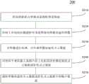
图4示出了根据本申请一个实施方式在骨科手术中利用光学三维扫描设备对骨骼表面进行测量的方法的流程图。如图4所示,该方法200可包括步骤S210、S220、S230。在步骤S210中,控制投影机向骨骼表面投影预设图案。在步骤S220中,控制工业相机拍摄投影有预设图案的骨骼表面的图像。在步骤S230中,对图像进行处理,以生成骨骼表面的点云数据。FIG. 4 shows a flow chart of a method for measuring a bone surface using an optical three-dimensional scanning device in orthopaedic surgery according to an embodiment of the present application. As shown in FIG. 4, the
参照上述针对光学三维扫描设备100的详细描述,可利用投影机向骨骼表面投影预设图案,与此同时,利用工业相机对该骨骼表面进行拍摄,从而能够获取投影有预设图案的骨骼表面的图像。利用该图像,可获知骨骼表面各点的术中空间坐标信息,以用于后续与患处骨骼表面的术前医学影像(例如,三维CT影像)的图像注册。Referring to the above detailed description of the optical three-
图5示出了根据本申请另一实施方式在骨科手术中利用光学三维扫描设备对骨骼表面进行测量的方法的流程图。如图5所示,除了步骤S210至S230之外,该方法200还可包括步骤S240和S250。为了简要起见,以下将仅描述图5所示的实施方式与图4的不同之处,并将略去其相同之处的详细描述。FIG. 5 shows a flowchart of a method for measuring a bone surface using an optical three-dimensional scanning device in orthopedic surgery according to another embodiment of the present application. As shown in FIG. 5, in addition to steps S210 to S230, the
如上所述,光学三维扫描设备100还可包括光学定位工具150,以用于设备自身定位。此外,在手术对象(即,患者)上可固定有另一光学定位工具。在步骤S240中,识别光学三维扫描设备100的光学定位工具150和固定在手术对象上的光学定位工具的空间位置。随后,在步骤S250中,利用光学定位工具150和固定在手术对象上的光学定位工具的空间位置,将骨骼表面的点云数据转换为患者的坐标系中的点云数据。由此,可将光学三维扫描设备100获取到的点云数据变换到患者坐标系中,以便于后续步骤。As mentioned above, the optical three-
根据本申请一个实施方式,上述预设图案可包括一组具有不同频率的黑白数字光栅图案。此时,步骤S230可包括以下子步骤:According to an embodiment of the present application, the above-mentioned preset pattern may include a group of black and white digital grating patterns with different frequencies. At this time, step S230 may include the following sub-steps:
通过工业相机拍摄的、投影有黑白数字光栅图案的骨骼表面的图像,计算得到骨骼表面上各点的三维坐标,并生成骨骼表面的点云数据。Through the image of the bone surface captured by an industrial camera and projected with a black and white digital raster pattern, the three-dimensional coordinates of each point on the bone surface are calculated, and the point cloud data of the bone surface is generated.
如上所述,利用预设图案中的一组具有不同频率的黑白数字光栅图案,可通过工业相机拍摄投影在骨骼表面的投影有该组具有不同频率的黑白数字光栅图案,并通过计算得到骨骼表面的点云数据。As mentioned above, using a set of black and white digital grating patterns with different frequencies in the preset patterns, the projection on the surface of the bone can be photographed by an industrial camera, and the set of black and white digital grating patterns with different frequencies can be projected on the surface of the bone, and the surface of the bone can be obtained by calculation. point cloud data.
进一步地,在方法200中使用的投影机可以是彩色投影机,工业相机可以是黑白工业相机,并且除了一组具有不同频率的黑白数字光栅图案之外,上述预设图案还可包括一组至少三种颜色的纯色图案。此时,除了上述子步骤之外,步骤S230还可包括以下子步骤:Further, the projector used in the
通过工业相机拍摄的、投影有纯色图案的骨骼表面的图像,计算得到骨骼表面上各点的色彩信息;以及The color information of each point on the bone surface is obtained by calculating the image of the bone surface with a solid color pattern projected by an industrial camera; and
利用色彩信息将骨骼表面的点云数据转换为彩色点云数据。Use color information to convert point cloud data on bone surface to color point cloud data.
如上所述,除了预设图案中的一组具有不同频率的黑白数字光栅图案之外,还可利用预设图案中的一组至少三种颜色的纯色图案,可通过工业相机拍摄投影在骨骼表面的投影有该组至少三种颜色的纯色图案,并通过计算得到骨骼表面上各点的色彩信息,从而将点云数据转换为彩色点云数据。As mentioned above, in addition to a group of black and white digital grating patterns with different frequencies in the preset patterns, a group of solid color patterns with at least three colors in the preset patterns can also be used, which can be photographed and projected on the bone surface by an industrial camera. The projection has the solid color pattern of the group of at least three colors, and the color information of each point on the bone surface is obtained by calculation, so as to convert the point cloud data into color point cloud data.
图6示出了根据本申请另一实施方式在骨科手术中利用光学三维扫描设备对骨骼表面进行测量的方法的流程图。如图6所示,除了步骤S210至S230之外,该方法200还可包括步骤S260。为了简要起见,以下将仅描述图6所示的实施方式与图4的不同之处,并将略去其相同之处的详细描述。FIG. 6 shows a flowchart of a method for measuring a bone surface using an optical three-dimensional scanning device in orthopedic surgery according to another embodiment of the present application. As shown in FIG. 6, in addition to steps S210 to S230, the
在步骤S260中,向骨科手术机器人系统中的上位机发送骨骼表面的点云数据或彩色点云数据。由此,操作人员可在上位机上利用患者患处骨骼表面的点云数据进行手术规划并控制手术机器人系统执行手术。In step S260, the point cloud data or color point cloud data of the bone surface is sent to the upper computer in the orthopedic surgery robot system. In this way, the operator can use the point cloud data of the patient's affected bone surface on the host computer for surgical planning and control the surgical robot system to perform surgery.
图7示出了根据本申请另一实施方式在骨科手术中利用光学三维扫描设备对骨骼表面进行测量的方法的流程图。如图7所示,除了步骤S210、S220、S230、S260之外,该方法200还可包括步骤S270。为了简要起见,以下将仅描述图7所示的实施方式与图6的不同之处,并将略去其相同之处的详细描述。FIG. 7 shows a flowchart of a method for measuring a bone surface using an optical three-dimensional scanning device in orthopaedic surgery according to another embodiment of the present application. As shown in FIG. 7, in addition to steps S210, S220, S230, and S260, the
在步骤S270中,去除骨骼表面的点云数据或彩色点云数据中的噪声数据。由于利用光学三维扫描设备所获取的骨骼表面的点云数据中,除了骨骼表面各点的数据,还会包含患者患处其他组织上各点的数据。此时,操作人员可在上位机上手动或自动地将骨骼表面的点云数据保留,而将其余部分的点云数据当作噪声去除。而上位机可以自动地识别噪声数据,或响应于操作人员的指令,去除噪声数据。特别有利的是,如果利用光学三维扫描设备所获取的骨骼表面的点云数据是彩色点云数据,将更加便于操作人员人工识别或上位机自动识别点云数据中术语骨骼表面的部分,从而予以保留,并去除其余部分的噪声数据。In step S270, the point cloud data or the noise data in the color point cloud data on the bone surface is removed. Because the point cloud data on the bone surface obtained by the optical three-dimensional scanning device, in addition to the data of each point on the bone surface, also includes the data of other points on the affected area of the patient. At this time, the operator can manually or automatically retain the point cloud data on the bone surface on the host computer, and remove the rest of the point cloud data as noise. The host computer can automatically identify the noise data, or remove the noise data in response to the operator's instruction. It is particularly advantageous that if the point cloud data of the bone surface obtained by the optical three-dimensional scanning device is color point cloud data, it will be more convenient for the operator to manually identify or the upper computer to automatically identify the part of the point cloud data that is termed as bone surface, so as to give Keep, and remove the rest of the noisy data.
图8示出了根据本申请一个实施方式骨科手术中的图像注册方法的流程图。该方法用于将术中获取的骨骼表面的图像与术前拍摄的骨骼表面的医学影像进行注册。如图8所示,该方法300可包括步骤S310、S320、S330。FIG. 8 shows a flowchart of an image registration method in orthopedic surgery according to one embodiment of the present application. The method is used to register the images of the bone surface acquired during the operation with the medical images of the bone surface captured before the operation. As shown in FIG. 8, the
在步骤S310中,在术前获取骨骼表面的术前医学影像。术前医学影像的获取方式将在下文中进行详细描述。在步骤S320中,利用上述方法200,在术中获取骨骼表面的术中点云数据。随后,在步骤S330中,将术中获取的骨骼表面的术中点云数据与术前获取的骨骼表面的术前医学影像进行注册。由此,可实现术中获取的骨骼表面的图像与术前拍摄的骨骼表面的医学影像的注册。In step S310, a preoperative medical image of the bone surface is acquired before the operation. The acquisition method of preoperative medical images will be described in detail below. In step S320, the above-mentioned
图9示出了根据本申请一个实施方式在术前获取骨骼表面的术前医学影像的流程图。如图9所示,上述步骤S310可包括子步骤S311至S313。FIG. 9 shows a flow chart of preoperatively acquiring preoperative medical images of the bone surface according to one embodiment of the present application. As shown in FIG. 9, the above-mentioned step S310 may include sub-steps S311 to S313.
在子步骤S311中,利用医学影像扫描仪,对人体患处进行扫描。该医学影像扫描仪可以是例如三维CT,在进行手术之前,需要对患者的患处部位拍摄CT影像,通过对CT影像进行分割、裁剪,仅保留手术需要处理的骨骼部位。In sub-step S311, a medical image scanner is used to scan the affected part of the human body. The medical image scanner can be, for example, a three-dimensional CT. Before performing an operation, a CT image of the affected part of the patient needs to be taken. By segmenting and cropping the CT image, only the bone parts that need to be processed in the operation are retained.
在子步骤S312中,根据扫描得到的医学影像,获取骨骼表面的等值面数据。由于诸如CT影像的术前医学影像中每个像素的CT值是局部组织或者器官密度的计量单位,反映了不同组织的密度信息,且理论上骨骼表面的密度趋向于某一固定CT数值,因此可以通过诸如Marching Cubes的三维等值面提取算法,获得CT图中患者的患处骨骼表面的等值面数据。In sub-step S312, the isosurface data of the bone surface is acquired according to the medical image obtained by scanning. Since the CT value of each pixel in preoperative medical images such as CT images is a measurement unit of local tissue or organ density, it reflects the density information of different tissues, and theoretically the density of the bone surface tends to a certain fixed CT value, so The isosurface data of the patient's bone surface in the CT image can be obtained through a three-dimensional isosurface extraction algorithm such as Marching Cubes.
在子步骤S313中,对等值面数据进行采样,得到骨骼表面的术前点云数据。通常情况下,采用诸如Marching Cubes的三维等值面提取算法提取出的骨骼表面的等值面数据是三角面片形式的骨骼表面信息,还需要对这些三角面片信息进行采样来获取点云数据,即获取点云形式的术前患者患处部位骨骼表面信息。由此,可对患者患处的术前骨骼表面医学影像处理完毕,以用于后续的图像注册。In sub-step S313, the isosurface data is sampled to obtain preoperative point cloud data on the bone surface. Usually, the isosurface data of the bone surface extracted by the three-dimensional isosurface extraction algorithm such as Marching Cubes is the bone surface information in the form of triangular patches, and it is also necessary to sample the triangular patch information to obtain point cloud data. , that is, to obtain the preoperative bone surface information of the affected part of the patient in the form of a point cloud. In this way, the preoperative bone surface medical images of the patient's affected area can be processed for subsequent image registration.
图10示出了根据本申请一个实施方式将术中获取的骨骼表面的术中点云数据与术前获取的骨骼表面的术前医学影像进行注册的流程图。如图10所示,上述步骤S330可包括子步骤S331至S333。FIG. 10 shows a flowchart of registering intraoperative point cloud data of the bone surface acquired during the operation with the preoperative medical image of the bone surface acquired before the operation according to an embodiment of the present application. As shown in FIG. 10 , the above-mentioned step S330 may include sub-steps S331 to S333.
在实际的注册操作中,可将术前患者患处骨骼表面的点云数据(即,术前医学影像)作为固定点云,将术中患者患处骨骼表面的点云数据(即,术中点云数据)作为浮动点云,通过在空间中对浮动点云进行空间刚体变换,实现两者之间的注册,且使注册误差尽量小。在子步骤S331中,在术前医学影像和术中点云数据中选取对应点对。在浮动点云与固定点云中选取若干个对应点对,对应点对的个数应大于等于3。同一组对应点对需要选自于两组点云数据对应患者患处骨骼表面的同一位置。在进行对应点对的选择时,算法所需的最少点对的数量是3,但是没有上限要求。根据本申请的一个实施例,可选取4组对应点对,这样既能保证粗略注册阶段的准确性,又避免了选取过多对应点对时操作的复杂性。在选择某一组对应点对时,只要保证这一组点对分别在浮动点云和固定点云上处于大致相同的位置亦可,不一定要求所有点对都能保持对齐,粗略注册阶段只是进行初始粗略的对齐,即多个点对的综合误差最小即可。In the actual registration operation, the point cloud data on the bone surface of the affected part of the patient before surgery (ie, the preoperative medical image) can be used as a fixed point cloud, and the point cloud data on the bone surface of the affected part of the patient during the operation (ie, the intraoperative point cloud) can be used as a fixed point cloud. data) as a floating point cloud, by performing spatial rigid body transformation on the floating point cloud in space, the registration between the two is realized, and the registration error is minimized. In sub-step S331, corresponding point pairs are selected from the preoperative medical image and the intraoperative point cloud data. Select several corresponding point pairs from the floating point cloud and the fixed point cloud, and the number of corresponding point pairs should be greater than or equal to 3. The same set of corresponding point pairs needs to be selected from the two sets of point cloud data corresponding to the same position on the bone surface of the patient's affected area. When selecting the corresponding point pairs, the minimum number of point pairs required by the algorithm is 3, but there is no upper limit requirement. According to an embodiment of the present application, four sets of corresponding point pairs can be selected, which can not only ensure the accuracy of the rough registration stage, but also avoid the complexity of the operation when too many corresponding point pairs are selected. When selecting a certain set of corresponding point pairs, it is only necessary to ensure that the set of point pairs are in roughly the same position on the floating point cloud and the fixed point cloud respectively. It is not necessarily required that all point pairs can be kept aligned. The initial rough alignment is performed, that is, the comprehensive error of multiple point pairs is the smallest.
在子步骤S332中,利用所选取的对应点对,将术中点云数据与术前医学影像进行粗略注册。注册过程可分为两个阶段:(1)粗略注册阶段、(2)精细注册阶段。粗略注册阶段主要是将浮动点云与固定点云进行空间中的粗略、大致对齐;精细注册阶段则是在粗略注册阶段的基础上,再进行两点云之间的精细对齐,使注册精度误差降到最低。在子步骤S332的粗略注册阶段中,根据对应点对选取的特性,浮动点云上选取的对应点与固定点云上选取的对应点具有大致相同的形状位置关系,根据若干对应点对可以计算出一个初始的空间刚体变换矩阵RT1,从而实现浮动点云与固定点云之间的粗略注册。上述变换矩阵RT1是通过人为的选取浮动点云与固定点云的对应点对来计算的,由于是人工在浮动点云与固定点云上选取的“人看来相同位置”的对应点,而实际上这些点对会存在一定位置上的偏差,因此在进行了坐标变换后这些对应点对有可能并不是完全一致或者重合,因此在粗略注册阶段计算出来的变换矩阵RT1只是保证了对应点对之间的距离最为接近。In sub-step S332, using the selected corresponding point pairs, the intraoperative point cloud data and the preoperative medical image are roughly registered. The registration process can be divided into two stages: (1) coarse registration stage, (2) fine registration stage. The rough registration stage mainly aligns the floating point cloud and the fixed point cloud roughly and roughly in space; the fine registration stage is based on the rough registration stage, and then performs fine alignment between the two point clouds to make the registration accuracy error. drop to lowest. In the rough registration stage of sub-step S332, according to the selected characteristics of the corresponding point pairs, the corresponding points selected on the floating point cloud and the corresponding points selected on the fixed point cloud have approximately the same shape and position relationship, and can be calculated according to several corresponding point pairs. An initial space rigid body transformation matrix RT1 is obtained, so as to realize the rough registration between the floating point cloud and the fixed point cloud. The above-mentioned transformation matrix RT1 is calculated by artificially selecting the corresponding point pairs of the floating point cloud and the fixed point cloud, because it is the corresponding point that "people seem to be in the same position" manually selected on the floating point cloud and the fixed point cloud, and In fact, these point pairs will have a certain positional deviation, so after the coordinate transformation, these corresponding point pairs may not be completely consistent or coincident, so the transformation matrix RT1 calculated in the rough registration stage only guarantees the corresponding point pairs The distance between them is the closest.
在子步骤S333中,基于粗略注册的结果,利用预设的迭代算法,将术中点云数据与术前医学影像进行精细注册。在粗略注册阶段完成后,为了进一步提高整体注册精度,降低误差,需要进行精细注册。不同于粗略注册阶段仅针对从浮动点云与固定点云中选取的对应点对进行计算处理,精细注册阶段需要考虑点云数据中的所有点,其得到的空间刚体变换矩阵RT2是在粗略注册阶段的基础上利用预设的迭代算法(例如,迭代最近点(IterativeClosest Point,ICP)算法)不断计算迭代优化得到的,使最终注册误差最小。使用ICP算法的前提是固定点云与浮动点云已经过了粗略注册阶段,使得两点云在空间中距离基本对齐。ICP算法能够使不同的坐标下的点云数据合并到同一个坐标系统中,首先是找到一个可用的变换,配准操作实际是要找到从一个坐标系到另一坐标系的一个刚性变换。ICP算法本质上是基于最小二乘法的最优配准方法。该算法重复进行选择对应关系点对,计算最优刚体变换,直到满足正确配准的收敛精度要求。ICP算法的目的是要找到待配准点云数据与参考云数据之间的旋转参数R和平移参数T,使得两点数据之间满足某种度量准则下的最优匹配。In sub-step S333, based on the result of the rough registration, a preset iterative algorithm is used to finely register the intraoperative point cloud data and the preoperative medical image. After the rough registration phase is completed, in order to further improve the overall registration accuracy and reduce errors, fine registration is required. Unlike the rough registration stage, which only calculates the corresponding point pairs selected from the floating point cloud and the fixed point cloud, the fine registration stage needs to consider all points in the point cloud data, and the obtained spatial rigid body transformation matrix RT2 is in the rough registration stage. On the basis of each stage, a preset iterative algorithm (for example, iterative Closest Point (Iterative Closest Point, ICP) algorithm) is used to continuously calculate the result obtained by iterative optimization, so as to minimize the final registration error. The premise of using the ICP algorithm is that the fixed point cloud and the floating point cloud have passed the rough registration stage, so that the distance between the two point clouds is basically aligned in space. The ICP algorithm can merge point cloud data under different coordinates into the same coordinate system. The first step is to find an available transformation. The registration operation is actually to find a rigid transformation from one coordinate system to another. The ICP algorithm is essentially an optimal registration method based on the least squares method. The algorithm repeatedly selects corresponding relationship point pairs and calculates the optimal rigid body transformation until the convergence accuracy requirements for correct registration are met. The purpose of the ICP algorithm is to find the rotation parameter R and translation parameter T between the point cloud data to be registered and the reference cloud data, so that the two point data meet the optimal matching under a certain metric criterion.
图11示出了根据本申请另一实施方式将术中获取的骨骼表面的术中点云数据与术前获取的骨骼表面的术前医学影像进行注册的流程图。如图11所示,除了子步骤S331至S333之外,该步骤S330还可包括子步骤S334。为了简要起见,以下将仅描述图11所示的实施方式与图10的不同之处,并将略去其相同之处的详细描述。FIG. 11 shows a flowchart of registering intraoperative point cloud data of the bone surface acquired during the operation with the preoperative medical image of the bone surface acquired before the operation according to another embodiment of the present application. As shown in FIG. 11 , in addition to the sub-steps S331 to S333 , this step S330 may further include a sub-step S334 . For the sake of brevity, only the differences between the embodiment shown in FIG. 11 and FIG. 10 will be described below, and the detailed description of the similarities will be omitted.
在子步骤S334中,将粗略注册得到的第一变换矩阵与精细注册得到的第二变换矩阵相叠加,得到最终注册变换矩阵。完成精细注册之后,将粗略注册产生的变换矩阵RT1与精细注册产生的变换矩阵RT2进行叠加,产生一个新的变换矩阵RT3。即,RT3=RT2*RT1。通过变换矩阵RT3即可实现术中患者患处骨骼表面图像与术前患者患处CT影像的注册。完成整体非接触式的表面测量以及与术前患者影像的注册工作。In sub-step S334, the first transformation matrix obtained by the rough registration and the second transformation matrix obtained by the fine registration are superimposed to obtain the final registration transformation matrix. After the fine registration is completed, the transformation matrix RT1 generated by the coarse registration and the transformation matrix RT2 generated by the fine registration are superimposed to generate a new transformation matrix RT3. That is, RT3=RT2*RT1. Through the transformation matrix RT3, the registration of the intraoperative bone surface image of the patient's affected area and the preoperative CT image of the patient's affected area can be realized. Complete overall non-contact surface measurement and registration with preoperative patient images.
根据本申请的一个方面,提供了一种手术机器人系统,其包括如上所述的光学三维扫描设备100。According to one aspect of the present application, there is provided a surgical robot system including the optical three-
根据本申请的另一方面,提供了一种电子设备,其包括处理器和存储器,该存储器存储有计算机程序,当该计算机程序被该处理器执行时,使得该处理器执行如上所述的方法200或300。According to another aspect of the present application, an electronic device is provided, which includes a processor and a memory, the memory stores a computer program, and when the computer program is executed by the processor, causes the processor to execute the method as described above 200 or 300.
根据本申请的另一方面,提供了一种非瞬时性计算机可读存储介质,其上存储有计算机可读指令,当该指令被处理器执行时,使得该处理器执行如上所述的方法200或300。According to another aspect of the present application, there is provided a non-transitory computer-readable storage medium having computer-readable instructions stored thereon which, when executed by a processor, cause the processor to perform the
下面参考图12,其示出了适于用来实现本申请实施例的服务器的计算机系统400的结构示意图。图12示出的服务器仅仅是一个示例,不应对本申请实施例的功能和使用范围带来任何限制。Referring to FIG. 12 below, it shows a schematic structural diagram of a
如图12所示,计算机系统400包括中央处理单元(CPU)401,其可以根据存储在只读存储器(ROM)402中的程序或者从存储部分408加载到随机访问存储器(RAM)403中的程序而执行各种适当的动作和处理。在RAM 403中,还存储有系统400操作所需的各种程序和数据。CPU 401、ROM 402以及RAM 403通过总线404彼此相连。输入/输出(I/O)接口405也连接至总线404。As shown in FIG. 12, a
以下部件连接至I/O接口405:包括键盘、鼠标等的输入部分406;包括诸如阴极射线管(CRT)、液晶显示器(LCD)等以及扬声器等的输出部分407;包括硬盘等的存储部分408;以及包括诸如LAN卡、调制解调器等的网络接口卡的通信部分409。通信部分409经由诸如因特网的网络执行通信处理。驱动器410也根据需要连接至I/O接口405。可拆卸介质411,诸如磁盘、光盘、磁光盘、半导体存储器等等,根据需要安装在驱动器410上,以便于从其上读出的计算机程序根据需要被安装入存储部分408。The following components are connected to the I/O interface 405: an
特别地,根据本公开的实施例,上文参考流程图描述的过程可以被实现为计算机软件程序。例如,本公开的实施例包括一种计算机程序产品,其包括承载在计算机可读介质上的计算机程序,该计算机程序包含用于执行流程图所示的方法的程序代码。在这样的实施例中,该计算机程序可以通过通信部分409从网络上被下载和安装,和/或从可拆卸介质411被安装。在该计算机程序被中央处理单元(CPU)401执行时,执行本申请的方法中限定的上述功能。需要说明的是,本申请的计算机可读介质可以是计算机可读信号介质或者计算机可读存储介质或者是上述两者的任意组合。计算机可读存储介质例如可以是——但不限于——电、磁、光、电磁、红外线、或半导体的系统、装置或器件,或者任意以上的组合。计算机可读存储介质的更具体的例子可以包括但不限于:具有一个或多个导线的电连接、便携式计算机磁盘、硬盘、随机访问存储器(RAM)、只读存储器(ROM)、可擦式可编程只读存储器(EPROM或闪存)、光纤、便携式紧凑磁盘只读存储器(CD-ROM)、光存储器件、磁存储器件、或者上述的任意合适的组合。在本申请中,计算机可读存储介质可以是任何包含或存储程序的有形介质,该程序可以被指令执行系统、装置或者器件使用或者与其结合使用。而在本申请中,计算机可读的信号介质可以包括在基带中或者作为载波一部分传播的数据信号,其中承载了计算机可读的程序代码。这种传播的数据信号可以采用多种形式,包括但不限于电磁信号、光信号或上述的任意合适的组合。计算机可读的信号介质还可以是计算机可读存储介质以外的任何计算机可读介质,该计算机可读介质可以发送、传播或者传输用于由指令执行系统、装置或者器件使用或者与其结合使用的程序。计算机可读介质上包含的程序代码可以用任何适当的介质传输,包括但不限于:无线、电线、光缆、RF等等,或者上述的任意合适的组合。In particular, according to embodiments of the present disclosure, the processes described above with reference to the flowcharts may be implemented as computer software programs. For example, embodiments of the present disclosure include a computer program product comprising a computer program carried on a computer-readable medium, the computer program containing program code for performing the method illustrated in the flowchart. In such an embodiment, the computer program may be downloaded and installed from the network via the
可以以一种或多种程序设计语言或其组合来编写用于执行本申请的操作的计算机程序代码,程序设计语言包括面向对象的程序设计语言—诸如Java、Smalltalk、C++,还包括常规的过程式程序设计语言—诸如”C”语言或类似的程序设计语言。程序代码可以完全地在用户计算机上执行、部分地在用户计算机上执行、作为一个独立的软件包执行、部分在用户计算机上部分在远程计算机上执行、或者完全在远程计算机或服务器上执行。在涉及远程计算机的情形中,远程计算机可以通过任意种类的网络——包括局域网(LAN)或广域网(WAN)—连接到用户计算机,或者,可以连接到外部计算机(例如利用因特网服务提供商来通过因特网连接)。Computer program code for performing the operations of the present application may be written in one or more programming languages, including object-oriented programming languages—such as Java, Smalltalk, C++, and also conventional procedures, or a combination thereof programming language - such as "C" or a similar programming language. The program code may execute entirely on the user's computer, partly on the user's computer, as a stand-alone software package, partly on the user's computer and partly on a remote computer, or entirely on the remote computer or server. In the case of a remote computer, the remote computer may be connected to the user's computer through any kind of network, including a local area network (LAN) or a wide area network (WAN), or may be connected to an external computer (eg, using an Internet service provider through Internet connection).
附图中的流程图和框图,图示了按照本申请各种实施例的系统、方法和计算机程序产品的可能实现的体系架构、功能和操作。在这点上,流程图或框图中的每个方框可以代表一个模块、程序段、或代码的一部分,该模块、程序段、或代码的一部分包含一个或多个用于实现规定的逻辑功能的可执行指令。也应当注意,在有些作为替换的实现中,方框中所标注的功能也可以以不同于附图中所标注的顺序发生。例如,两个接连地表示的方框实际上可以基本并行地执行,它们有时也可以按相反的顺序执行,这依所涉及的功能而定。也要注意的是,框图和/或流程图中的每个方框、以及框图和/或流程图中的方框的组合,可以用执行规定的功能或操作的专用的基于硬件的系统来实现,或者可以用专用硬件与计算机指令的组合来实现。The flowchart and block diagrams in the Figures illustrate the architecture, functionality, and operation of possible implementations of systems, methods and computer program products according to various embodiments of the present application. In this regard, each block in the flowchart or block diagrams may represent a module, segment, or portion of code that contains one or more logical functions for implementing the specified functions executable instructions. It should also be noted that, in some alternative implementations, the functions noted in the blocks may occur out of the order noted in the figures. For example, two blocks shown in succession may, in fact, be executed substantially concurrently, or the blocks may sometimes be executed in the reverse order, depending upon the functionality involved. It is also noted that each block of the block diagrams and/or flowchart illustrations, and combinations of blocks in the block diagrams and/or flowchart illustrations, can be implemented in dedicated hardware-based systems that perform the specified functions or operations , or can be implemented in a combination of dedicated hardware and computer instructions.
描述于本申请实施例中所涉及到的单元可以通过软件的方式实现,也可以通过硬件的方式来实现。所描述的单元也可以设置在处理器中。The units involved in the embodiments of the present application may be implemented in a software manner, and may also be implemented in a hardware manner. The described unit may also be provided in a processor.
作为另一方面,本申请还提供了一种计算机可读介质,该计算机可读介质可以是上述实施例中描述的装置中所包含的;也可以是单独存在,而未装配入该装置中。上述计算机可读介质承载有一个或者多个程序,当上述一个或者多个程序被该装置执行时,使得该装置执行如上所述的方法。As another aspect, the present application also provides a computer-readable medium, which may be included in the apparatus described in the above-mentioned embodiments, or may exist independently without being assembled into the apparatus. The above-mentioned computer-readable medium carries one or more programs, which, when executed by the apparatus, cause the apparatus to perform the above-mentioned method.
在上述实施例中,对各个实施例的描述都各有侧重,某个实施例中没有详述的部分,可以参见其他实施例的相关描述。上述实施例的各技术特征可以进行任意的组合,为使描述简洁,未对上述实施例中的各个技术特征所有可能的组合都进行描述,然而,只要这些技术特征的组合不存在矛盾,都应当认为是本说明书记载的范围。In the above-mentioned embodiments, the description of each embodiment has its own emphasis. For parts that are not described in detail in a certain embodiment, reference may be made to the relevant descriptions of other embodiments. The technical features of the above embodiments can be combined arbitrarily. For the sake of brevity, all possible combinations of the technical features in the above embodiments are not described. However, as long as there is no contradiction in the combination of these technical features, it should be It is considered to be the range described in this specification.
以上对本申请实施例进行了详细介绍,本文中应用了具体个例对本申请的原理及实施方式进行了阐述,以上实施例的说明仅用于帮助理解本申请的方法及其核心思想。同时,本领域技术人员依据本申请的思想,基于本申请的具体实施方式及应用范围上做出的改变或变形之处,都属于本申请保护的范围。综上所述,本说明书内容不应理解为对本申请的限制。The embodiments of the present application are described in detail above, and specific examples are used herein to illustrate the principles and implementations of the present application. The descriptions of the above embodiments are only used to help understand the methods and core ideas of the present application. Meanwhile, any changes or deformations made by those skilled in the art based on the ideas of the present application and the specific embodiments and application scope of the present application fall within the protection scope of the present application. In conclusion, the content of this specification should not be construed as a limitation on the present application.
Claims (20)
Translated fromChinesePriority Applications (1)
| Application Number | Priority Date | Filing Date | Title |
|---|---|---|---|
| CN202010187835.8ACN111493878A (en) | 2020-03-17 | 2020-03-17 | Optical three-dimensional scanning device for orthopedic surgery and method for measuring bone surface |
Applications Claiming Priority (1)
| Application Number | Priority Date | Filing Date | Title |
|---|---|---|---|
| CN202010187835.8ACN111493878A (en) | 2020-03-17 | 2020-03-17 | Optical three-dimensional scanning device for orthopedic surgery and method for measuring bone surface |
Publications (1)
| Publication Number | Publication Date |
|---|---|
| CN111493878Atrue CN111493878A (en) | 2020-08-07 |
Family
ID=71874297
Family Applications (1)
| Application Number | Title | Priority Date | Filing Date |
|---|---|---|---|
| CN202010187835.8APendingCN111493878A (en) | 2020-03-17 | 2020-03-17 | Optical three-dimensional scanning device for orthopedic surgery and method for measuring bone surface |
Country Status (1)
| Country | Link |
|---|---|
| CN (1) | CN111493878A (en) |
Cited By (6)
| Publication number | Priority date | Publication date | Assignee | Title |
|---|---|---|---|---|
| CN112155732A (en)* | 2020-09-29 | 2021-01-01 | 苏州微创畅行机器人有限公司 | Readable storage medium, bone modeling and registering system and bone surgery system |
| CN112826590A (en)* | 2021-02-02 | 2021-05-25 | 复旦大学 | A spatial registration system for knee arthroplasty based on multimodal fusion and point cloud registration |
| CN113576664A (en)* | 2021-07-30 | 2021-11-02 | 武汉联影智融医疗科技有限公司 | Point cloud space registration method, device and equipment and optical projection device |
| CN115245384A (en)* | 2021-04-27 | 2022-10-28 | 杭州素问九州医疗科技有限公司 | Skeleton registration method and system, robot system and storage medium |
| CN115607276A (en)* | 2022-10-14 | 2023-01-17 | 苏州微创畅行机器人有限公司 | Method, system, storage medium and computer product for guiding bone registration |
| CN115670649A (en)* | 2021-07-26 | 2023-02-03 | 杭州素问九州医疗科技有限公司 | Bone registration method and system, surgical robot system, and storage medium |
Citations (10)
| Publication number | Priority date | Publication date | Assignee | Title |
|---|---|---|---|---|
| CN101301200A (en)* | 2008-05-29 | 2008-11-12 | 上海交通大学 | Method for Measuring Three-Dimensional Facial Topography of Patients with Facial Defects |
| CN101305899A (en)* | 2008-07-09 | 2008-11-19 | 中国科学院上海光学精密机械研究所 | Three-dimensional endoscopic measurement device and method based on amplitude-type transmission grating projection |
| CN101739717A (en)* | 2009-11-12 | 2010-06-16 | 天津汇信软件有限公司 | Non-contact scanning method for three-dimensional colour point clouds |
| CN102784003A (en)* | 2012-07-20 | 2012-11-21 | 北京先临华宁医疗科技有限公司 | Pediculus arcus vertebrae internal fixation operation navigation system based on structured light scanning |
| US20150193963A1 (en)* | 2014-01-08 | 2015-07-09 | Here Global B.V. | Systems and Methods for Creating an Aerial Image |
| CN106137395A (en)* | 2016-07-22 | 2016-11-23 | 华南理工大学 | It is applied to the full-automatic patient registry method of unmarked some optical operation navigation system |
| CN107330926A (en)* | 2017-08-25 | 2017-11-07 | 上海嘉奥信息科技发展有限公司 | Non-marked medical figure registration system and method in a kind of art in navigation system |
| CN107874832A (en)* | 2017-11-22 | 2018-04-06 | 合肥美亚光电技术股份有限公司 | Bone surgery set navigation system and method |
| CN107898499A (en)* | 2017-12-06 | 2018-04-13 | 上海波城医疗科技有限公司 | Orthopaedics 3D region alignment system and method |
| CN109751969A (en)* | 2017-11-01 | 2019-05-14 | 天津微深科技有限公司 | A kind of three-dimensional non-contact scanning method using positive and negative Gray's code line shifted raster |
- 2020
- 2020-03-17CNCN202010187835.8Apatent/CN111493878A/enactivePending
Patent Citations (10)
| Publication number | Priority date | Publication date | Assignee | Title |
|---|---|---|---|---|
| CN101301200A (en)* | 2008-05-29 | 2008-11-12 | 上海交通大学 | Method for Measuring Three-Dimensional Facial Topography of Patients with Facial Defects |
| CN101305899A (en)* | 2008-07-09 | 2008-11-19 | 中国科学院上海光学精密机械研究所 | Three-dimensional endoscopic measurement device and method based on amplitude-type transmission grating projection |
| CN101739717A (en)* | 2009-11-12 | 2010-06-16 | 天津汇信软件有限公司 | Non-contact scanning method for three-dimensional colour point clouds |
| CN102784003A (en)* | 2012-07-20 | 2012-11-21 | 北京先临华宁医疗科技有限公司 | Pediculus arcus vertebrae internal fixation operation navigation system based on structured light scanning |
| US20150193963A1 (en)* | 2014-01-08 | 2015-07-09 | Here Global B.V. | Systems and Methods for Creating an Aerial Image |
| CN106137395A (en)* | 2016-07-22 | 2016-11-23 | 华南理工大学 | It is applied to the full-automatic patient registry method of unmarked some optical operation navigation system |
| CN107330926A (en)* | 2017-08-25 | 2017-11-07 | 上海嘉奥信息科技发展有限公司 | Non-marked medical figure registration system and method in a kind of art in navigation system |
| CN109751969A (en)* | 2017-11-01 | 2019-05-14 | 天津微深科技有限公司 | A kind of three-dimensional non-contact scanning method using positive and negative Gray's code line shifted raster |
| CN107874832A (en)* | 2017-11-22 | 2018-04-06 | 合肥美亚光电技术股份有限公司 | Bone surgery set navigation system and method |
| CN107898499A (en)* | 2017-12-06 | 2018-04-13 | 上海波城医疗科技有限公司 | Orthopaedics 3D region alignment system and method |
Cited By (8)
| Publication number | Priority date | Publication date | Assignee | Title |
|---|---|---|---|---|
| CN112155732A (en)* | 2020-09-29 | 2021-01-01 | 苏州微创畅行机器人有限公司 | Readable storage medium, bone modeling and registering system and bone surgery system |
| CN112826590A (en)* | 2021-02-02 | 2021-05-25 | 复旦大学 | A spatial registration system for knee arthroplasty based on multimodal fusion and point cloud registration |
| CN115245384A (en)* | 2021-04-27 | 2022-10-28 | 杭州素问九州医疗科技有限公司 | Skeleton registration method and system, robot system and storage medium |
| CN115670649A (en)* | 2021-07-26 | 2023-02-03 | 杭州素问九州医疗科技有限公司 | Bone registration method and system, surgical robot system, and storage medium |
| CN115670649B (en)* | 2021-07-26 | 2025-07-18 | 杭州素问九州医疗科技有限公司 | Bone registration method and system, surgical robot system, and storage medium |
| CN113576664A (en)* | 2021-07-30 | 2021-11-02 | 武汉联影智融医疗科技有限公司 | Point cloud space registration method, device and equipment and optical projection device |
| CN113576664B (en)* | 2021-07-30 | 2024-05-28 | 武汉联影智融医疗科技有限公司 | Point cloud space registration method, device, equipment and optical projection device |
| CN115607276A (en)* | 2022-10-14 | 2023-01-17 | 苏州微创畅行机器人有限公司 | Method, system, storage medium and computer product for guiding bone registration |
Similar Documents
| Publication | Publication Date | Title |
|---|---|---|
| CN111493878A (en) | Optical three-dimensional scanning device for orthopedic surgery and method for measuring bone surface | |
| US11257241B2 (en) | System and method for component positioning by registering a 3D patient model to an intra-operative image | |
| CN110966932B (en) | A Structured Light 3D Scanning Method Based on Known Markers | |
| CN113974830B (en) | A surgical navigation system for ultrasound-guided thermal ablation of thyroid tumors | |
| JP5538667B2 (en) | Position / orientation measuring apparatus and control method thereof | |
| WO2021078065A1 (en) | Breast three-dimensional point cloud reconstruction method and apparatus, and storage medium and computer device | |
| JP2003130621A (en) | Method and system for measuring three-dimensional shape | |
| CN113034700A (en) | Anterior cruciate ligament reconstruction surgery navigation method and system based on mobile terminal | |
| CN112057107A (en) | Ultrasonic scanning method, ultrasonic equipment and system | |
| US10929706B2 (en) | Image processing device and projection system | |
| EP4052651A1 (en) | Image-based planning of tomographic scan | |
| CN106705890A (en) | Three-dimensional scanning magic box | |
| CN108937992A (en) | A kind of the visualized in situ system and its scaling method of radioscopy imaging | |
| CN116883471B (en) | Line structured light contact-point-free cloud registration method for chest and abdomen percutaneous puncture | |
| CN117058197A (en) | Spatial registration method and device for nerve regulation and control | |
| CN113662663B (en) | AR holographic surgery navigation system coordinate system conversion method, device and system | |
| CN111184535A (en) | Handheld Unconstrained Scanning Wireless 3D Ultrasound Real-time Voxel Imaging System | |
| CN117392230A (en) | CBCT rotation radius measurement method, device, equipment and storage medium | |
| JP3862402B2 (en) | 3D model generation apparatus and computer-readable recording medium on which 3D model generation program is recorded | |
| US20240175677A1 (en) | Measuring system providing shape from shading | |
| CN117414199A (en) | Intraoperative navigation system and method for skeletal correction surgery | |
| US10049480B2 (en) | Image alignment device, method, and program | |
| CN115607276A (en) | Method, system, storage medium and computer product for guiding bone registration | |
| JP2022094744A (en) | Subject motion measuring device, subject motion measuring method, program, imaging system | |
| CN115105202A (en) | Focus confirmation method and system used in endoscopic surgery |
Legal Events
| Date | Code | Title | Description |
|---|---|---|---|
| PB01 | Publication | ||
| PB01 | Publication | ||
| SE01 | Entry into force of request for substantive examination | ||
| SE01 | Entry into force of request for substantive examination | ||
| RJ01 | Rejection of invention patent application after publication | ||
| RJ01 | Rejection of invention patent application after publication | Application publication date:20200807 |