CN1114839C - Fiber optic splice sleeve - Google Patents
Fiber optic splice sleeveDownload PDFInfo
- Publication number
- CN1114839C CN1114839CCN96193327.5ACN96193327ACN1114839CCN 1114839 CCN1114839 CCN 1114839CCN 96193327 ACN96193327 ACN 96193327ACN 1114839 CCN1114839 CCN 1114839C
- Authority
- CN
- China
- Prior art keywords
- pair
- splice
- cable
- tray
- extending
- Prior art date
- Legal status (The legal status is an assumption and is not a legal conclusion. Google has not performed a legal analysis and makes no representation as to the accuracy of the status listed.)
- Expired - Fee Related
Links
Images


Classifications
- G—PHYSICS
- G02—OPTICS
- G02B—OPTICAL ELEMENTS, SYSTEMS OR APPARATUS
- G02B6/00—Light guides; Structural details of arrangements comprising light guides and other optical elements, e.g. couplings
- G02B6/44—Mechanical structures for providing tensile strength and external protection for fibres, e.g. optical transmission cables
- G02B6/4439—Auxiliary devices
- G02B6/444—Systems or boxes with surplus lengths
- G02B6/4441—Boxes
- G02B6/4446—Cable boxes, e.g. splicing boxes with two or more multi fibre cables
- G02B6/4447—Cable boxes, e.g. splicing boxes with two or more multi fibre cables with divided shells
- G—PHYSICS
- G02—OPTICS
- G02B—OPTICAL ELEMENTS, SYSTEMS OR APPARATUS
- G02B6/00—Light guides; Structural details of arrangements comprising light guides and other optical elements, e.g. couplings
- G02B6/44—Mechanical structures for providing tensile strength and external protection for fibres, e.g. optical transmission cables
- G02B6/4439—Auxiliary devices
- G02B6/444—Systems or boxes with surplus lengths
- G02B6/4452—Distribution frames
- G02B6/44524—Distribution frames with frame parts or auxiliary devices mounted on the frame and collectively not covering a whole width of the frame or rack
- G—PHYSICS
- G02—OPTICS
- G02B—OPTICAL ELEMENTS, SYSTEMS OR APPARATUS
- G02B6/00—Light guides; Structural details of arrangements comprising light guides and other optical elements, e.g. couplings
- G02B6/44—Mechanical structures for providing tensile strength and external protection for fibres, e.g. optical transmission cables
- G02B6/4439—Auxiliary devices
- G02B6/444—Systems or boxes with surplus lengths
- G02B6/44528—Patch-cords; Connector arrangements in the system or in the box
- G—PHYSICS
- G02—OPTICS
- G02B—OPTICAL ELEMENTS, SYSTEMS OR APPARATUS
- G02B6/00—Light guides; Structural details of arrangements comprising light guides and other optical elements, e.g. couplings
- G02B6/44—Mechanical structures for providing tensile strength and external protection for fibres, e.g. optical transmission cables
- G02B6/4439—Auxiliary devices
- G02B6/444—Systems or boxes with surplus lengths
- G02B6/4453—Cassettes
- G02B6/4454—Cassettes with splices
Landscapes
- Physics & Mathematics (AREA)
- General Physics & Mathematics (AREA)
- Optics & Photonics (AREA)
- Light Guides In General And Applications Therefor (AREA)
- Cable Accessories (AREA)
- Mechanical Coupling Of Light Guides (AREA)
Abstract
Description
Translated fromChinese发明背景Background of the invention
本发明涉及一种防水的电缆接头套组件。在研究中的这种型式的组件尤其适用于封装光纤电缆,本发明将参照所附的具体说明来进行描述;但该装置完全能适用于其它类型的电缆。The invention relates to a waterproof cable joint cover assembly. The type of assembly under study is particularly suitable for encapsulating fiber optic cables, and the invention will be described with reference to the accompanying specification; however, the device is fully applicable to other types of cables.
在已有技术中,有许多不同类型的光纤电缆套。这些已有的套或多或少能令人满意,但通常存在某些不便于使用或不能很容易地适合环境和条件变化的缺点。因此,本发明的一个主要目的是提供一种便于装配和使用的电缆套,它能被迅速地修改成适合于不同的使用场合,并能以许多不同的尺寸形成有托盘和/或内部支架,使接头的尺寸和数量在较大范围内变化。另外,本发明还提供一种便于接近以改变或增加套中接头数量的电缆套。本发明的电缆套可以在不干扰原来储存接头的情况下增加其有效尺寸,以适应系统尺寸的增加。In the prior art, there are many different types of fiber optic cable jackets. These known sleeves are more or less satisfactory, but generally suffer from certain disadvantages which are not convenient to use or which cannot be easily adapted to changes in circumstances and conditions. It is therefore a primary object of the present invention to provide a cable cover which is easy to assemble and use, which can be quickly modified for different applications and which can be formed with trays and/or internal supports in many different sizes, The size and number of joints can be varied in a wide range. Additionally, the present invention provides a cable cover that provides easy access to change or increase the number of splices in the cover. The cable cover of the present invention can increase its effective size without interfering with the original storage joint to accommodate the increase in system size.
发明概要Summary of the invention
按照本发明的一个方面,提供一种封装电缆接头的封套组件,它大体包括一对封套件,它们具有主体部分,主体部分的周边夹持凸缘向外延伸并彼此相对地定位,从而被夹于一起。夹持凸缘具有与主体部分相邻的内端部和自由的外端部。在内端部之间设有一弹性密封垫,在自由端部处设有一刚性肋条结构。相对夹持凸缘之间的肋条结构的总厚度大于密封垫未压缩的正常厚度,以使得当夹持凸缘合在一起时,接合先是发生在刚性肋条结构上,而后,与密封垫的密封接合需要施加足以使凸缘绕刚性肋条结构产生挠曲和扭转的夹持力。According to one aspect of the present invention, there is provided an enclosure assembly for enclosing a cable splice, which generally includes a pair of enclosure elements having a main body portion with peripheral gripping flanges extending outwardly and positioned relative to each other so as to be clamped together. The clamping flange has an inner end adjacent to the body portion and a free outer end. An elastic gasket is provided between the inner ends and a rigid rib structure is provided at the free ends. The total thickness of the rib structure between opposing clamping flanges is greater than the normal uncompressed thickness of the gasket so that when the clamping flanges are brought together, engagement occurs first at the rigid rib structure and then, with the seal against the gasket Engagement requires the application of a clamping force sufficient to cause the flange to flex and twist around the rigid rib structure.
上述的结构允许密封垫更为均匀地受压,并提供了改进的密封垫接合。The structure described above allows the gasket to be more evenly compressed and provides improved gasket engagement.
按照一个较有限的方面,肋条结构可以是一体地形成于一个或两个凸缘的外自由端上的一刚性突起,密封垫可以是位于凸缘之间的一或多个分离的密封垫件。According to a more limited aspect, the rib structure may be a rigid protrusion integrally formed on the outer free ends of one or both flanges and the gasket may be one or more separate gasket elements located between the flanges .
另外,按照一较有限的方面,最好用多个短距离均匀隔开的螺纹连接件将凸缘夹于一起,这些连接件穿过肋条结构和密封垫结构之间的凸缘。Additionally, and in a more limited aspect, the flanges are preferably clamped together by a plurality of short evenly spaced threaded connections passing through the flanges between the rib structure and the gasket structure.
按照本发明的另一个方面,封装电缆接头的封套组件大体包括彼此轴向隔开的第一和第二端板,它们之间形成一储存空间。穿过该储存空间延伸有一刚性扭转梁,其端部刚性连接于端板。一对相对的套件成形为封套住端板和储存空间。套件彼此可拆和密封地夹在一起和夹于端板上。扭转梁的轴向隔开位置处支承有一对向外延伸的杆。设有多个叠置的接头托盘延伸于这对杆之间。这些托盘具有轴向开口的端槽,这些端槽容纳杆,并被引导于杆上。在杆上设有合适的连接装置,用于可拆地将托盘组夹于一起,并夹于刚性扭转梁上。According to another aspect of the present invention, a jacket assembly enclosing a cable splice generally includes first and second end plates axially spaced from each other to define a storage space therebetween. A rigid torsion beam extends through the storage space, the ends of which are rigidly connected to the end plates. A pair of opposing sleeves are shaped to enclose the end panels and the storage space. The sets are detachably and sealingly clipped to each other and to the end plates. A pair of outwardly extending rods are supported at axially spaced locations of the torsion beam. A plurality of stacked splice trays are provided extending between the pair of bars. These trays have axially open end slots which accommodate the rods and are guided on them. Suitable attachment means are provided on the rods for detachably clamping the stack of pallets together and to the rigid torsion beam.
最好,按照一个较有限的方面,从扭转梁上延伸出来的杆制有螺纹,连接装置包含可拆地连接于它上面的一系板件。利用这种用来相对于封套组件内部而支承住接头托盘的特别结构,仅稍微松一下连接装置并向上枢转托盘叠的一端,就可将它们带槽的端部从与杆的接合中脱出。而后各托盘可从托盘叠中的位置枢转出,以便接近其中的接头。由于托盘叠中的各托盘可以快速地拆卸而无需拆卸整个托盘叠,因此这形成了一种非常合乎需要的结构。这样,可在任一托盘中替换和增加另外的接头或电缆。Preferably, according to a more limited aspect, the rod extending from the torsion beam is threaded and the connecting means comprises a series of plate members releasably connected thereto. With the special structure used to support the splice trays relative to the inside of the cuff assembly, it is only necessary to loosen the linkage slightly and pivot one end of the stack of trays upward to disengage their slotted ends from engagement with the rods . Each tray can then be pivoted out of position in the tray stack to access splices therein. This forms a very desirable structure since the individual pallets in the pallet stack can be quickly disassembled without dismantling the entire pallet stack. In this way, additional connectors or cables can be replaced and added in either tray.
按照本发明的又一个方面,接头托盘的较佳形式包括一模制塑料托盘,该托盘具有一大致为平的矩形底壁和隔开的、向上延伸的侧壁,这些侧壁由横向延伸的端壁连接。托盘可拆地连接有多个夹片,它们与底壁相隔第一距离,从至少侧壁上延伸出来,当光纤电缆置于托盘中时,它们覆盖住这些电缆。端壁在大致的中心处带有向外开口的槽,以允许托盘安装于一对隔开的平行杆之间。托盘最好具有一个枢接于其一个端壁的盖子。According to yet another aspect of the present invention, a preferred form of splice tray includes a molded plastic tray having a generally flat rectangular bottom wall and spaced, upwardly extending side walls defined by laterally extending End wall connection. The tray is detachably connected to a plurality of clips spaced a first distance from the bottom wall, extending from at least one of the side walls, and covering the fiber optic cables when placed in the tray. The end walls have an outwardly opening slot at approximately the center to allow the tray to fit between a pair of spaced apart parallel bars. The tray preferably has a cover pivotally connected to one end wall thereof.
在本发明的一个较有限的方面中,夹片是通过使一个向下延伸部分弹性地夹持于与侧壁相联的夹持槽中而可拆地连接于托盘。而且,侧壁具有使诸夹片设置成离底壁不同的选定距离从侧壁向外延伸到底壁上方的装置。In a more limited aspect of the invention, the clip is releasably attached to the tray by resiliently retaining a downwardly extending portion in a retaining groove associated with the side wall. Furthermore, the side wall has means for the clips to extend outwardly from the side wall over the bottom wall at different selected distances from the bottom wall.
本发明的还有一个目的在于提供这样一种封套组件,它具有彼此轴向隔开的第一和第二端板,它们之间形成一个储存空间。有一对刚性扭转梁以隔开的关系延伸通过储存空间,它们的端部连接于端板。接头托盘以叠置的关系由从一个扭转梁上延伸出来的支架支承于扭转梁之间。端板支架的空间由一对围绕端板延伸并封接于端板的可拆主封套件围住。所围住的空间的尺寸以及所支承的端托盘的数量可以通过更换封套件和扭转梁中的一个来增加。由于其它扭转梁仍保持住托盘和端板,因此这可以在不干扰端板或托盘叠的情况下完成。It is still another object of the present invention to provide such a cuff assembly having first and second end plates axially spaced from each other to define a storage space therebetween. A pair of rigid torsion beams extend in spaced relation through the storage space, their ends connected to the end plates. The splice trays are supported in stacked relationship between the torsion beams by brackets extending from one of the torsion beams. The space of the end plate support is surrounded by a pair of detachable main envelopes extending around the end plate and sealed to the end plate. The size of the enclosed space and the number of supported end trays can be increased by replacing one of the envelope set and the torsion beam. This can be done without disturbing the end plates or the stack of pallets as the other torsion beams still hold the pallets and end plates.
在较佳的形式中,托盘是以叠置的形式支承于从一扭转梁上延伸出来的平行杆,托盘叠的端部与这些杆相接合。更换封套和相关的扭转梁可使杆上能支承更多数量的托盘,只需要在托盘叠的顶部加入托盘就可以了。In a preferred form, the pallets are supported in stacks on parallel rods extending from a torsion beam, the ends of the stack of pallets engaging the rods. Replacing the envelope and associated torsion beams allows a greater number of pallets to be supported on the rod, simply by adding pallets at the top of the pallet stack.
本发明还有其它的优点和益处,它们将为本技术领域的技术人员在阅读和理解了下面的详细描述后所了解。Still other advantages and benefits of the present invention will be apparent to those of ordinary skill in the art upon reading and understanding the following detailed description.
附图简述Brief description of the drawings
本发明可采取一定部件和部件结构的物理形式,其较佳的实施例和方法将详细描述于下面的说明书中,并示于作为其组成部分的附图之中,图中:The present invention, which may take physical form in certain components and component structures, is described in detail in the following description and in the drawings which form a part hereof, and in which:
图1是用来储存光纤电缆接头的封套组件的一较佳实施例的立体图;Figure 1 is a perspective view of a preferred embodiment of a sleeve assembly for storing fiber optic cable splices;
图2是图1封套组件的立体分解图;Fig. 2 is a three-dimensional exploded view of the envelope assembly in Fig. 1;
图2a是用于封套组件的主要构件之间的密封垫的立体图;Figure 2a is a perspective view of the gasket used between the main components of the cuff assembly;
图2b是将总储存空间增至其最大尺寸时所用的上扭转梁的改进形式的立体图;Figure 2b is a perspective view of a modification of the upper torsion beam used to increase the total storage space to its maximum size;
图3是构造细节略微放大的剖视图(沿图1的3-3线剖开);Fig. 3 is a slightly enlarged sectional view (cut along line 3-3 of Fig. 1 ) of construction details;
图4是沿图2中的4-4线剖开的略微放大的剖视图;Fig. 4 is a slightly enlarged cross-sectional view taken along line 4-4 in Fig. 2;
图5是可用于图1和2所示封套组件中的接头托盘第一种形式的高倍放大的立体图;Figure 5 is a highly enlarged perspective view of a first form of splice tray usable in the envelope assembly shown in Figures 1 and 2;
图5a是沿图5中的5a-5a线剖开的放大剖视图;Figure 5a is an enlarged sectional view taken along
图5b是沿图5中的5b-5b线剖开的放大剖视图;Figure 5b is an enlarged sectional view taken along
图6与图5相似,只是所示接头托盘的盖子经过改进,并且保持片的配置有所不同;Figure 6 is similar to Figure 5, except that the cover of the splice tray shown is modified and the configuration of the retaining tab is different;
图7是图5和图6中圈出区域的放大的平面图,示出了用来将盖件保持于接头托盘的闭合位置的卡销机构;Figure 7 is an enlarged plan view of the area circled in Figures 5 and 6, showing the detent mechanism used to retain the cover in the closed position of the splice tray;
图8是用于图1和图2封套组件中的储存托盘和支架组件的立体分解图;Figure 8 is an exploded perspective view of the storage tray and stand assembly used in the envelope assembly of Figures 1 and 2;
图8A是储存区域的另一种形式的立体图,其中省去了储存托盘,电缆储存区域用连接于下支承梁的托架件来提供;Figure 8A is a perspective view of an alternative form of storage area wherein the storage tray is omitted and the cable storage area is provided by bracket members attached to the lower support beam;
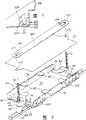
图9是本发明接头套的一种典型的“使用中”的结构示图,其壳状的主套件被除去。Figure 9 is an illustration of a typical "in-use" configuration of the connector housing of the present invention with the shell-like main sleeve removed.
较佳实施例详述DETAILED DESCRIPTION OF THE PREFERRED EMBODIMENT
下面参照附图,图中所示的内容仅用来说明本发明的较佳实施例,而不是对它的限制,参照图1和图2最能了解接头套A较佳构造的整体配置。如图所示,接头套A的主外套包括封套组件10,该封套组件封装有一接头托盘支承组件11。封套组件10大体由一对非常相似的、相对的主封套或主体件12和14形成,它们以密封夹紧的关系连接于一起,从而形成一个轴向细长的中心储存腔16。储存腔16的相对端由圆筒形的端板件18和20封闭,这些端板件可拆和密封地与主封套件12和14相接合,其接合方式将在下面描述。Referring to the accompanying drawings below, the content shown in the figures is only used to illustrate the preferred embodiment of the present invention, rather than to limit it, and the overall configuration of the preferred structure of the joint sleeve A can be best understood with reference to Figures 1 and 2. As shown, the main housing of the splice housing A includes a
虽然封套本体构件和端板可以由各种不同材料用不同的制造技术形成,但在本发明的实施例中,它们最好是由一种含加强纤维的合适的塑料注塑而成。例如,可优先选用由玻璃纤维加强的聚丙烯。While the cuff body members and end plates may be formed from a variety of materials using different manufacturing techniques, in the embodiment of the invention they are preferably injection molded from a suitable plastic material containing reinforcing fibers. For example, polypropylene reinforced with glass fibers may be preferred.
两个主封套件12、14在整体形状和结构上非常相似。因此,除了另外指明,对封套件12的描述应认为是可完全适用于封套件14。在研究的实施例中,主封套件12具有一细长的、半圆筒形的形状,从而形成一略呈壳状的本体,该本体具有一主外部半圆筒形壁22,该壁有沿各纵向侧延伸的侧向延伸夹持凸缘24。凸缘24相对壁22在直径方向成一直线,并形成平的密封和夹持面,这些夹持面沿各侧部是连续的。主壁22通过与壁22形成一体的、径向延伸且轴向隔开的诸肋条26来加强。每根肋条26沿圆周方向绕壁22延伸,其端部与夹持凸缘24相连接,如图所示。除了加强肋条26,最好还有纵向延伸的肋条28,它们于图示位置延伸于壁22的轴向端部之间。The two main envelope sets 12, 14 are very similar in overall shape and structure. Accordingly, the description of
为便于装配、拆卸和使用该接头储存封套组件10,至少有一些肋条26具有允许主体构件12、14稳定地置于一个工作平面上的径向的外部轮廓。参照图1和图2,可以看出,在封套件的每个端部处的最后两根肋条26各具有一平顶面30,该平面最好是在与夹持凸缘24的夹持面平行的一个平面内。显然,这允许封套和本体部分12、14在组件装配时或是在联接光纤电缆接头和将其安装于封套内时搁置于一工作平面上。To facilitate assembly, disassembly and use of the joint
可以用各种不同的可拆固定件或夹持装置来将主体构件12、14夹持于一起。然而在主实施例中,较为可取的形式是包括多个装于封套本体部分12中的柱螺栓32,这些螺栓的下螺纹端向下延伸通过相应的夹持凸缘24。在图示的形式中,柱螺栓32沿各夹持凸缘24均匀隔开地设置在诸模铸凸台34中。最好是用锁位环将柱螺栓34的头部36保持于凸台中,使得允许这些螺栓旋转,但不让它们轻易地脱出相应凸台34中的功能位置。A variety of different removable fasteners or clamping devices may be used to clamp the
具体先参照本体部分14,可以看出,本体部分14的夹持凸缘24在相应于主体件12上柱螺栓32的位置上具有垂直延伸通过相关凸缘的诸孔38。与各孔38相联的是被收集于件14的夹持凸缘24上的凸台40中的一螺旋桨螺母(未示出)。这样,两个半套12和14能通过柱螺栓32而夹持于一起。实际的夹持和密封结构将在后面描述。但现在先提一下,纵向隔开设置的各主体件12和14的轴向端部均具有一向内延伸的端凸缘部分42,该端凸缘部分具有一中央槽44,其形状和尺寸适于容纳相关端板18或20的外周边。Referring first to the
与各槽44以及各封套件12和14上的夹持凸缘24的纵向延伸的夹持面相联的是一弹性密封垫部件46,在图2A中可清楚地看出。密封垫46中的一个是粘结于各主体件12和14中的适当位置。如图所示,该实施例中所用的密封垫部件大体包括半圆筒形端部46a,它们隔开设置和构造成嵌入隔开的槽44内。拱式的半圆筒形端部46a由相对较窄的纵向延伸条46b连接。部分46a和46b的定位和结构可以在图2、3和4中看到。应注意的是,部分46b紧邻于壁22的内圆周而延伸,拱形端部46a向下延伸入相关的槽44内。槽44和相关的密封垫部分46a最好具有配合肋条和凹槽47(示于图4中),以增加粘结面和提高密封垫46的保持和密封能力。关于这一点,在安装密封垫46时,最好使用胶和粘结剂的混合材料。例如,将密封胶涂于中央槽47a中,并将一合适的粘结剂涂于各外侧的槽47b中。Associated with each
再参照端板18、20,应予理解的是,端板的尺寸和形状适于紧密和牢固地容纳于槽44中,以便用槽44底部的相关密封垫部分46a绕着它们的外周面而密封地接合。端板18、20最好由与主体部分12和14相同的材料模制而成。先参照端板20(见图2和9),可以看到,板20具有一个宽度在轴向方向上的圆形外周面,它将紧密地容纳于槽44中。板20是单个的、整体的一模制件,它具有一连续的外周面,该外周面绕其圆周形成有多个向外延伸的密封肋条50。肋条50设置用来与位于槽44底部中的密封垫部分46a密封接合。端板的中央形成数个合适的电缆孔52,其数量可按需要而设定。在该实施例中,有四个电缆孔52。最好,电缆孔52通常由内嵌式顶出件密封,当需要使用这些顶出件时,能从电缆孔52内驱动它们。在外圆周面和电缆孔52之间延伸有合适的交叉撑条和肋条,它们与主盘壁54连接成一体。所示的隔开设置的金属角形托架56用螺栓连接于端板20内表面上的适当位置。托架56的用途和功能将在后面描述。With reference again to the
端板20内还形成有诸附加的小孔52a,每个孔与一个电缆孔52相关联。这些孔提供一种将电缆强度件连接支架用螺栓连接于端板上的装置,其连接方式和用途将参照端板18进行描述。Additional apertures 52a are formed in the
端板18在结构上与端板20非常相似,但它是三部分组成的结构,包括一个中心部分58和两个外侧部分60。各构件被模制成图示的结构,并配置形成六个电缆通孔62。电缆通孔62可以是任何所需的尺寸,既可以是所有的尺寸均相同,也可以是具有各种不同的尺寸。但在该实施例中,四个外侧的孔具有相同的尺寸,而两个内侧的孔相对较小,但尺寸彼此相同。
构件58和60由一对延伸通过垂直对准的孔的系紧螺栓64连接成图示的形状和结构。构件58、60的外密封表面具有径向延伸的肋条部分,其形式与以上针对端板20所描述的肋条50相同。在某些方面,最好使用三部分组成的端板,这是因为,如果需要的话,它允许在连接端板件之前将电缆设置到位。当然,那些不使用的孔62可以用合适的、夹持于适当位置的孔塞或用其它方法来堵塞。最好,该装置设有孔塞,这些孔塞具有不同尺寸的相对端,以对应于两个不同尺寸的孔。这样使每个孔塞都能用来塞住两者中的每一个尺寸的孔。
如从图9中可清楚看出的,应该注意,每个孔62具有一电缆强度件支架61和一与它相联的连接孔62a。为说明强度件支架的功能,每个光纤电缆通常带有一细长的线状强度件,用于加强电缆的强度,或更准确地说,加强电缆内光纤输送管的强度。在电缆通入封套后,将这些强度件从输送管上切去。为了将电缆固定于封套,需要将强度件固定于强度件支架上。而且,由于强度件的伸缩率不同于光纤本身,因此,重要的是,强度件的移动不能传递到接头或是光纤。这样,强度件连接支架不仅能将电缆牢固地固定于封套,而且能将接头和光纤与强度件的伸缩所造成的移动相隔离。As can be seen clearly from FIG. 9, it should be noted that each
端板18和20由延伸于各端板上的托架56之间的、类似系杆的金属扭矩或扭转梁63、65刚性地连接成适当对准并隔开的关系。当然,下梁件63是用螺栓连接于各端板上的最下面的托架56,上梁件65平行于下梁件而可拆地螺栓连接于上托架56对之间。这种结构使得端板和托盘支承组件成为一个独立的、刚性的、整体的分组件,其结构强度和整体性不依赖于外部封套件。这种结构的重要性将在下面变得更明显。The
具体参照图3,夹持凸缘的结构将进行更为具体的描述,以表示出这个可以获得提高的密封性能的结构。具体地说,如图3所示,构件12上的凸缘24在它们的外侧自由端具有一肋条状突起24a,该突起从相关的凸缘向下朝构件14的相对的凸缘部分24延伸。刚性肋条24a的总高度是这样的,使得在正常的接合位置下,密封垫部分46b相隔开,如图3所示。但随着柱螺栓被拧紧,凸缘24绕刚性肋条24a彼此相对枢转,装于各半部12和14上的相对的密封垫部分46b被彼此相对带动,并形成密封接台。这种使凸缘枢转和使它们绕刚性肋条24a挠曲的结构可改善密封垫的扭转和密封。Referring specifically to FIG. 3, the structure of the clamping flange will be described in more detail to show that this structure can achieve improved sealing performance. Specifically, as shown in FIG. 3, the
在两个半部被密封和连于一起后,可以进行测试,测定是否已实现充分的流体密封。为此,主体部分12具有一个加压阀68,从图1和图2中可看出。可以将一种合适的加压测试流体或气体通过该阀送入内腔16,以测定密封性能。After the two halves are sealed and joined together, a test can be performed to determine whether a sufficient fluid seal has been achieved. For this purpose, the
如上所述,腔16内装有托盘支承组件11,它带有一或多个接头托盘,并还可供多余电缆的存放。较佳的形式示于图2和图8中,图8A中示出一个修改的形式。图2和图8的形式是用来与单管型光纤电缆一起使用的,它具有一个储存托盘69。图8A的形式是用来与缓冲的电缆一起使用的,它依靠在支架上,这些支架在接头托盘下提供一个开放的空间,用于存放多余长度的电缆。As mentioned above,
在图2和图8的形式中,储存托盘69以及叠置的接头托盘支承于下系杆件63,该系杆件连接在下托架56之间,并用可拆螺栓适当地连接于这些托架上。如上所述,上托架56之间也连接有一上系杆件,从而,这两根系杆大致平行地延伸,用于使端板定位和适当隔开,同时保持它们适当的对齐,并大大增加整个组件的强度。在这种形式中,储存托盘69如上所述直接支承和连接于下系杆63。应注意的是,有一对平行的、隔开的螺杆或螺栓70延伸通过下系杆63中合适的孔并从该孔向上延伸。杆70上套有合适的垫圈72,以使储存托盘69保持在系杆上方的一个所需的高度。在该结构中,象以上所述,储存托盘69是用来保持和提供一个供多余长度的单管型光缆能够盘绕和搁置的地方,因为以后可能需要改变或增加接头。In the form of Figures 2 and 8, the
虽然储存托盘可采用各种不同的形状,所示出的是一个大致呈U形的矩形盒,它具有一底壁74和向上延伸的侧壁76。矩形盒结构的相对端打开,以允许打算盘绕和储存于储存托盘中的电缆方便地引入和自由地接纳。与底部74和侧壁76的端部相邻的是多个通孔78,它们在所示的位置延伸穿过底部和侧壁的宽度。通过使用传统的电缆扣或类似物,这些通孔78提供了使电缆能牢固地固定于储存托盘上的结构。在侧壁76的上端设有可移动的L形保持件80,通常称作夹片。这些L形保持件80可拆地保持在形成于侧壁76中的、合适的向下延伸槽内。每个保持件具有一个向下延伸的腿部82,它延伸入一相关的侧壁槽内,弹性保持于其中。保持件80在组件的使用过程中可以拆下,以允许将电缆圈定位于托盘中。在储存的电缆部分定位于储存托盘中后,可将保持件或夹片移到适当位置,以将储存的电缆相对于底壁74适当地向下保持住,并以后面将进行描述的方式也支承住压在其上面的接头托盘。While the storage tray can take a variety of shapes, what is shown is a generally U-shaped rectangular box having a
具体地参照图8和储存托盘底部74的相对端部,可以看出,它上面一体地形成有向上延伸的安装柱部分84,该部分具有一个向外延伸的三角形部分86,该三角形部分带有一个中心孔88,用于接纳相关的螺杆70。当托盘移至图2中所示位置时,将一螺母89拧到各杆上,用于将储存托盘刚性地锁于系杆件70上的适当位置。如果需要的话,通过连接于底壁74下表面的、形状、尺寸和位置适于与主体14的壁22的弧形内表面相接合的合适的弯曲金属腿件90,可增加托盘相对于封套的稳定性和刚性。另外,还应注意的是,柱子84最好在它们的上表面形成有一个合适的槽,用于接纳一片以上关于侧壁76所描述的夹片。8 and the opposite end of the
如果需要的话,可在储存托盘69的上方设置一块合适的盖板77以提供对储存于其中的电缆附加的保护,该盖板带有端孔77a,端孔的尺寸和位置适于接纳杆70。If desired, a
如前面所提到的,当组件与缓冲过的电缆一起使用时,本发明设想使用支架来支承叠置的接头托盘。图8A示出了这种支架109的较佳形式以及它们与下梁件63的关系。具体地说,每个支架109的形状大致呈U形,在腿部的上端处有向内延伸的水平支承部分109a。这些支架用所示合适的螺栓连接于下梁件63。设置向下弯曲的小片109b用来接合于梁件63的侧边。这些小片使支架定中心和定位,并防止它们相对于梁件63转动。支架内和支承口下方的空间可提供盘绕和储存多余长度的光缆用的空间。As previously mentioned, the present invention contemplates the use of brackets to support stacked splice trays when the assembly is used with buffered cables. A preferred form of
如上所述,一个或多个接头托盘91在储存托盘69或支架109的上方设置成叠置关系,它们用来以有条理的方式保持相关光纤电缆中的接头连接件。虽然接头托盘可具有各种形状,但该实施例中托盘的通常和较佳的形式是示于图5、5A和5B中。如图中所示,接头托盘91大体包括一矩形的模制塑料托盘件,其外围尺寸和形状呈矩形,并大致与下面的储存托盘的尺寸和形状相对应。如图5中所示,该托盘具有一平的底壁90和一向上延伸的侧壁92。端壁大体由向上延伸的整体结构形成,上端(从图5中看)形成有有一电缆引入区94,该引入区对着托盘的内部打开,并具有多个隔开的垂直延伸壁96,这些壁形成一组分离的通道,光纤电缆组通过这些通道可引入托盘的内部。图5中托盘的下端具有一个成形的圆内壁面98,它有利于电缆弯曲以及在托盘内盘绕成卷而定位。与托盘的上内端相联的是一突起的拱形壁100,它也用来引导电缆,使它适当地绕托盘的内部整齐地盘绕。As noted above, one or
与储存托盘中所使用的结构一样,图5中所示的接头托盘也具有保持件或夹片80,它们可拆地保持于侧壁和端壁的适当位置。图5A示出了夹片保持于侧壁92中适当位置所采用的方式。具体地说,每个夹片80的向下延由的腿部82可拆地容纳于一个沿各壁92形成的纵向延伸槽102中。端壁中和内端壁100中也具有用于夹片的类似槽。Like the structure used in storage trays, the splice tray shown in Figure 5 also has retainers or clips 80 which are releasably held in place on the side and end walls. FIG. 5A shows the manner in which the clip is held in place in the
参照图5B,可以看出,槽102内侧上的内壁部分92a通过在其上表面设切口104而具有高度变化的部分,该切口从内壁部分92a的顶边向下延伸。切口104的长度等于夹片80的宽度,使得这些夹片能容纳于其中。这使得夹片能从图5和5A中所示的上方高度移动到由切口104形成的下方高度。当然,在这样的移位中,夹片必须轴向移动。这种移位随着对图6托盘形式的描述而变得更为清楚。这种移位允许在托盘上使用不同类型的盖件,并允许保持片相对于相关托盘的底部90具有不同的高度,以对应托盘中的不同光纤数量而进行调整。Referring to FIG. 5B, it can be seen that the inner wall portion 92a on the inner side of the
与托盘的底壁90相联的是多个向上延伸的弹性薄板条108,它们大致垂直于侧部而延伸,并最好与底壁形成一体,以形成多个向上开口的、横向延伸的槽。诸薄板条108之间的间隔,也就是槽的宽度,选定为能让用来形成接头的连接件夹持于其中。沿薄板条108的列,在不同点这些宽度可以变化,因而能以有条理和简便的方式来夹持各种在市场上可以买到的和通用的连接件。最好,在薄板条108之间的诸位置处,于托盘的底部90上开槽(未示出),以便于拆除夹持于薄板条之间的接头连接件。也就是说,这些槽允许将螺丝起子或类似物穿过托盘底部向上插入,从而将连接件推出薄板条之间的空间。该实施例还通过使用数条位于托盘底部上邻接槽110相对端的双面压敏胶带112,为连接件及相关光纤电缆的保持到位提供了选择方案。Associated with the
图5的托盘具有一平的顶部114,该顶部最好由一种透明的塑料模塑而成,以允许在盖子处于关闭位置时看到托盘的内部。图5表示盖子114枢转到打开位置。可以用许多不同类型的铰接装置将盖子114铰接于托盘,但在该实施例中,合适的枢销116从侧壁92侧向朝外延伸,并接合于从盖子114上向下延伸出来的整体的钩扣件118。钩扣件118最好具有背侧开口,以使得将盖子移到所示的其上方位置时,可以很容易地将它拉出枢销116。The tray of Figure 5 has a flat top 114 which is preferably molded from a clear plastic to allow the interior of the tray to be seen when the lid is in the closed position. Figure 5 shows the
盖子还设置成当它们处于关闭位置时会栓住托盘。从图7中可清楚地看出,托盘的端部在每个外角处具有一掣子结构,该掣子结构包括一弹性的L形掣子件120,它通过一打开区122和一向内延伸的槽124与托盘的其余部分相分离。有一小突起126从L形掣子120的腿部120a的侧面延伸入空间122。如虚线所示,通过朝箭头128方向施加推力,掣于120的可以挠曲到虚线位置。然后,这使得掣子件120移动到左侧,如图7中所示。与掣件120相配合,并可接合于突起126下面的是盖子114下侧面所带有的(见图5)、用来进入与突起126相邻的空间122的钩扣130,它钩在突起126的下面,将盖子保持于关闭位置。朝箭头128方向压推掣子件120,可使突起126侧向移动而松开钩扣130,允许盖子移动到其打开位置。虽然仅描述了一个掣子件和钩扣件130,但应予注意的是,在托盘和盖子另一个角上也设有第二套同样的相对掣手。The lids are also configured to latch the trays when they are in the closed position. As can be clearly seen in Figure 7, the end of the tray has a detent structure at each outer corner comprising a resilient L-shaped
图6表示接头托盘的第二种稍作改进的形式,并进一步示出可多重定位的夹片80。在图6的实施例中,所示的夹片80被提至最高的位置。在该提升的位置,在托盘中可获得更大的空间用来封装光纤电缆。而且,在该提起位置,盖件140最好沿其边缘设有槽142,以允许侧夹片容纳于其中。此外,盖子的中央最好形成圆供顶,如144所表示,以使得槽108中可封装更大的连接件。FIG. 6 shows a second, slightly modified version of the splice tray and further illustrates the multiple positionable clips 80. As shown in FIG. In the embodiment of Figure 6, the
接头托盘91与系杆63相接合,并成叠置关系保持于它上面,其所采用的方式参照图2和图5最便于理解。具体地说,每个托盘91均具有形成向外开口的槽150的端结构。槽150的尺寸和间隔适于接纳隔开的螺柱70。这样,可将两个或多个托盘91的托盘叠定位于储存托盘69的上方,并通过柱子70在托盘69上保持叠置的对齐关系。设有一合适的弹性塑料系板152,用来连接两柱子70的上端,并以相对系杆63和储存托盘69或支架109一定的位置关系而向下夹持住托盘叠。如图所示,系板152具有端孔154,这些端孔具有用来延伸成与螺柱70相接合并将系板可拆地锁在柱70上的弹性片156。但只需提起这些弹性片,就可拆去系板。
托盘91相对于柱子70的所述安装方式所产生的一个重要的优点在于,储存的托盘叠中的下部几个托盘,无需全部移去上面所叠置的托盘就可接近。只需松开系板152,就能向上提起托盘叠的一端,直到那一端上的槽脱离相关的柱子70。而后,各个被选中的下部托盘可以从托盘叠中的其它托盘之间朝外枢转,而该托盘的另一端任保持与另一柱子相接合。在该托盘中的工作完成后,反过来执行上述程序即可使它回到托盘叠中的所处位置。An important advantage resulting from the described mounting of
该较佳实施例的封套结构所产生的一个主要的优点在于,它在不干扰或拆卸以前所装配的接头托盘91以及整个托盘支承组件11的情况下增加储存腔有效尺寸的能力。为了理解本发明的这一方面,应注意的是,如上面所讨论的,可以将外封套件12和14从它们与端板18和20的夹持接合分离开来,而不会影响其余结构,即端板18、20,系杆63、65以及储存和接头托盘的结构整体性。这样,可重新安装内部尺寸较大的主封套件(只要它们的端凸缘部分42与端板18和20的尺寸相对应)。所有的这些可在不干扰以前所建立的托盘组的情况下进行。A major advantage created by the envelope structure of the preferred embodiment is its ability to increase the effective size of the storage cavity without disturbing or disassembling previously assembled
除此以外,还可进一步增加在需要增大储存托盘叠的高度时可以利用的空间,进而允许安装比原有的最大托盘数量更多的托盘。这可以通过拆去上系杆63,并换以如图2b所示的一修改的系杆160来实现。应注意的是,拆下和调换上系杆不会影响或改变端板和储存托盘分组件的结构整体性。但修改的系杆却借助其弓形或向上弯曲的中央部分而提供了额外的空间,用于增加储存托盘叠的高度。而且,如果需要或必要的话,杆70的高度可以通过加到它们上端部的适当的延伸部分来增大。In addition to this, it is possible to further increase the space available when the height of the storage pallet stack needs to be increased, thereby allowing the installation of more pallets than the original maximum number of pallets. This can be accomplished by removing the
上面已参照较佳的实施例描述了本发明。显然,其他人在阅读和理解了本说明书后可以进行修改和变化。如果这些修改和变化落在所附权利要求或其它等同内容的范围之内,则它们理应包括在本发明内。The invention has been described above with reference to the preferred embodiments. Obviously, modifications and alterations will occur to others upon reading and understanding this specification. Such modifications and changes are intended to be included in the present invention if they come within the scope of the appended claims or their equivalents.
Claims (26)
Translated fromChineseApplications Claiming Priority (2)
| Application Number | Priority Date | Filing Date | Title |
|---|---|---|---|
| US08/426,624 | 1995-04-20 | ||
| US08/426,624US5631993A (en) | 1995-04-20 | 1995-04-20 | Optical fiber splice case |
Related Child Applications (1)
| Application Number | Title | Priority Date | Filing Date |
|---|---|---|---|
| CN03123834.3ADivisionCN1253739C (en) | 1995-04-20 | 1996-04-08 | Optical fiber splice case system |
Publications (2)
| Publication Number | Publication Date |
|---|---|
| CN1181816A CN1181816A (en) | 1998-05-13 |
| CN1114839Ctrue CN1114839C (en) | 2003-07-16 |
Family
ID=23691559
Family Applications (2)
| Application Number | Title | Priority Date | Filing Date |
|---|---|---|---|
| CN03123834.3AExpired - Fee RelatedCN1253739C (en) | 1995-04-20 | 1996-04-08 | Optical fiber splice case system |
| CN96193327.5AExpired - Fee RelatedCN1114839C (en) | 1995-04-20 | 1996-04-08 | Fiber optic splice sleeve |
Family Applications Before (1)
| Application Number | Title | Priority Date | Filing Date |
|---|---|---|---|
| CN03123834.3AExpired - Fee RelatedCN1253739C (en) | 1995-04-20 | 1996-04-08 | Optical fiber splice case system |
Country Status (8)
| Country | Link |
|---|---|
| US (7) | US5631993A (en) |
| EP (1) | EP0821801A4 (en) |
| JP (1) | JP3151559B2 (en) |
| CN (2) | CN1253739C (en) |
| AU (1) | AU696894B2 (en) |
| BR (1) | BR9608281A (en) |
| CA (1) | CA2218350A1 (en) |
| WO (1) | WO1996033431A1 (en) |
Cited By (18)
| Publication number | Priority date | Publication date | Assignee | Title |
|---|---|---|---|---|
| CN110998395A (en)* | 2017-06-28 | 2020-04-10 | 康宁光电通信有限责任公司 | Multiports having connection ports with associated securing features and methods of making the same |
| US11294133B2 (en) | 2019-07-31 | 2022-04-05 | Corning Research & Development Corporation | Fiber optic networks using multiports and cable assemblies with cable-to-connector orientation |
| US11487073B2 (en) | 2019-09-30 | 2022-11-01 | Corning Research & Development Corporation | Cable input devices having an integrated locking feature and assemblies using the cable input devices |
| US11536921B2 (en) | 2020-02-11 | 2022-12-27 | Corning Research & Development Corporation | Fiber optic terminals having one or more loopback assemblies |
| US11604320B2 (en) | 2020-09-30 | 2023-03-14 | Corning Research & Development Corporation | Connector assemblies for telecommunication enclosures |
| US11650388B2 (en) | 2019-11-14 | 2023-05-16 | Corning Research & Development Corporation | Fiber optic networks having a self-supporting optical terminal and methods of installing the optical terminal |
| US11668890B2 (en) | 2017-06-28 | 2023-06-06 | Corning Research & Development Corporation | Multiports and other devices having optical connection ports with securing features and methods of making the same |
| US11686913B2 (en) | 2020-11-30 | 2023-06-27 | Corning Research & Development Corporation | Fiber optic cable assemblies and connector assemblies having a crimp ring and crimp body and methods of fabricating the same |
| US11703646B2 (en) | 2017-06-28 | 2023-07-18 | Corning Research & Development Corporation | Multiports and optical connectors with rotationally discrete locking and keying features |
| US11880076B2 (en) | 2020-11-30 | 2024-01-23 | Corning Research & Development Corporation | Fiber optic adapter assemblies including a conversion housing and a release housing |
| US11886010B2 (en) | 2019-10-07 | 2024-01-30 | Corning Research & Development Corporation | Fiber optic terminals and fiber optic networks having variable ratio couplers |
| US11927810B2 (en) | 2020-11-30 | 2024-03-12 | Corning Research & Development Corporation | Fiber optic adapter assemblies including a conversion housing and a release member |
| US11947167B2 (en) | 2021-05-26 | 2024-04-02 | Corning Research & Development Corporation | Fiber optic terminals and tools and methods for adjusting a split ratio of a fiber optic terminal |
| US11994722B2 (en) | 2020-11-30 | 2024-05-28 | Corning Research & Development Corporation | Fiber optic adapter assemblies including an adapter housing and a locking housing |
| US12019279B2 (en) | 2019-05-31 | 2024-06-25 | Corning Research & Development Corporation | Multiports and other devices having optical connection ports with sliding actuators and methods of making the same |
| US12044894B2 (en) | 2018-12-28 | 2024-07-23 | Corning Research & Development Corporation | Multiport assemblies including mounting features or dust plugs |
| US12271040B2 (en) | 2017-06-28 | 2025-04-08 | Corning Research & Development Corporation | Fiber optic extender ports, assemblies and methods of making the same |
| US12372727B2 (en) | 2020-10-30 | 2025-07-29 | Corning Research & Development Corporation | Female fiber optic connectors having a rocker latch arm and methods of making the same |
Families Citing this family (183)
| Publication number | Priority date | Publication date | Assignee | Title |
|---|---|---|---|---|
| WO1996010203A1 (en)* | 1994-09-28 | 1996-04-04 | Telephone Cables Limited | A splice tray |
| US5568584A (en)* | 1995-03-20 | 1996-10-22 | Psi Telecommunications, Inc. | Fiber optic closure with cable adapter spool |
| US5793920A (en)* | 1995-03-20 | 1998-08-11 | Psi Telecommunications, Inc. | Method and apparatus for anchoring an optical fiber cable |
| US5631993A (en)* | 1995-04-20 | 1997-05-20 | Preformed Line Products Company | Optical fiber splice case |
| US5644671A (en)* | 1995-06-23 | 1997-07-01 | Preformed Line Products Company | Optical fiber spice case with cross connect feature |
| US5835657A (en)* | 1995-12-08 | 1998-11-10 | Psi Telecommunications, Inc. | Fiber optic splice tray |
| KR0177101B1 (en)* | 1996-01-25 | 1999-05-15 | 김광호 | The optical fiber splicer protector/supporter |
| US5647045A (en)* | 1996-02-23 | 1997-07-08 | Leviton Manufacturing Co., Inc. | Multi-media connection housing |
| JPH09304631A (en)* | 1996-05-14 | 1997-11-28 | Japan Riicom:Kk | Closure for cable connection |
| US7457962B2 (en)* | 1996-07-02 | 2008-11-25 | Wistaria Trading, Inc | Optimization methods for the insertion, protection, and detection of digital watermarks in digitized data |
| AU4897097A (en)* | 1996-10-25 | 1998-05-22 | Tyco Submarine Systems Ltd. | Submarine cable joint with branching joint assembly |
| US8079086B1 (en) | 1997-11-06 | 2011-12-13 | Finjan, Inc. | Malicious mobile code runtime monitoring system and methods |
| US9219755B2 (en) | 1996-11-08 | 2015-12-22 | Finjan, Inc. | Malicious mobile code runtime monitoring system and methods |
| JP3856890B2 (en)* | 1997-03-03 | 2006-12-13 | 株式会社フジクラ | Fiber optic cable closure |
| US5907653A (en)* | 1997-05-01 | 1999-05-25 | Lucent Technologies Inc. | Racetrack grommet for optical fiber cable splice closure |
| KR100261762B1 (en)* | 1997-12-02 | 2000-07-15 | 이계철 | Optical ribbon fiber splice tray |
| AU2971599A (en)* | 1998-02-20 | 1999-09-06 | Alcoa Fujikura Limited | Fiber optic splice enclosure |
| FR2775845B1 (en)* | 1998-03-09 | 2000-04-14 | Alsthom Cge Alcatel | WATERPROOF CABLE ACCESS HOUSING |
| JP4044668B2 (en)* | 1998-03-09 | 2008-02-06 | 株式会社ジャパンリーコム | End face seal member in cable wiring closure |
| US6009225A (en)* | 1998-05-26 | 1999-12-28 | Ray; Craig D. | Fiber optic drop splice closure and related methods |
| US6976093B2 (en)* | 1998-05-29 | 2005-12-13 | Yahoo! Inc. | Web server content replication |
| US7143193B1 (en)* | 1998-05-29 | 2006-11-28 | Yahoo! Inc. | Content collection |
| US6014490A (en)* | 1998-06-05 | 2000-01-11 | Siecor Operation, Llc | Optical fiber interconnection closure having a fiber management frame |
| US6215939B1 (en)* | 1998-07-02 | 2001-04-10 | Preformed Line Products Company | Optical fiber splice case with integral cable clamp, buffer cable storage area and metered air valve |
| DE19832821C1 (en)* | 1998-07-21 | 1999-12-02 | Siemens Ag | Optical cable connector box |
| NL1013707C2 (en)* | 1998-12-01 | 2003-04-11 | Felten & Guilleaume Ag Oester | Device for guiding and reversing light waveguides. |
| WO2000033118A1 (en)* | 1998-12-02 | 2000-06-08 | Tyco Elctronics Raychem Nv | Fibre optic management |
| US6275640B1 (en)* | 1999-04-21 | 2001-08-14 | Tyco Electrtonics Corporation | Fiber optic splice closure including end pivoting slack storage holder with adjustable rear wall and associated methods |
| ES2189756T3 (en)* | 1999-04-26 | 2003-07-16 | Tyco Electronics Raychem Nv | CLOSURE BOX. |
| US6367730B1 (en) | 1999-05-25 | 2002-04-09 | Tycom (Us) Inc. | Device for storing optical fibers |
| US6347760B1 (en) | 1999-05-25 | 2002-02-19 | Tycom (Us) Inc. | Device for storing optical fibers |
| US6353697B1 (en)* | 1999-07-30 | 2002-03-05 | Lucent Technologies, Inc. | Modular layered splice holder |
| US6356695B1 (en)* | 1999-07-30 | 2002-03-12 | Lucent Technologies, Inc. | Variable Depth/Stackable Optical Fiber Separator |
| US6292614B1 (en) | 1999-08-24 | 2001-09-18 | Siecor Operations, Llc | Movable bracket for holding internal components of an optical fiber interconnection closure during servicing and associated method |
| US6411767B1 (en) | 1999-08-24 | 2002-06-25 | Corning Cable Systems Llc | Optical fiber interconnection closures |
| US6322019B1 (en)* | 1999-09-08 | 2001-11-27 | Tycom (Us) Inc. | Device for covering a jacketed fiber storage space |
| US6533472B1 (en)* | 1999-10-19 | 2003-03-18 | Alcoa Fujikura Limited | Optical fiber splice closure assembly |
| US6226436B1 (en)* | 1999-11-18 | 2001-05-01 | Lucent Technologies, Inc. | Fiber optical pedestal |
| US6519395B1 (en)* | 2000-05-04 | 2003-02-11 | Northrop Grumman Corporation | Fiber optic array harness |
| US6381397B1 (en)* | 2000-05-04 | 2002-04-30 | Northrop Grumman Corporation | Fiber optic array breakout housing |
| AU2002213249A1 (en)* | 2000-10-17 | 2002-04-29 | Preformed Line Products Company | Cable closure and assembly |
| US6539160B2 (en)* | 2000-10-27 | 2003-03-25 | Corning Cable Systems Llc | Optical fiber splicing and connecting assembly with coupler cassette |
| US6434313B1 (en)* | 2000-10-31 | 2002-08-13 | Corning Cable Systems Llc | Fiber optic closure with couplers and splice tray |
| US6763170B2 (en)* | 2001-02-02 | 2004-07-13 | Tyco Telecommunications (Us) Inc. | System for storing splices in a joint box |
| MXPA03010718A (en)* | 2001-05-25 | 2005-03-07 | Preformed Line Products Co | Fiber optic cable closure. |
| DE10141129A1 (en)* | 2001-07-19 | 2003-02-20 | Norddeutsche Seekabelwerk Gmbh | Coupling sleeve for a submarine cable with an optical waveguide has a casing for holding adjacent cable ends and a retaining area in the casing for coupling points for optical waveguide ends |
| US6744962B2 (en) | 2001-10-25 | 2004-06-01 | Uniseal, Inc. | Fiberoptic splice closure |
| FR2832226B1 (en)* | 2001-11-13 | 2004-10-22 | Nexans | OPTICAL FIBER DISTRIBUTION AND CONNECTION MODULE FOR AN OPTICAL DISTRIBUTOR |
| GB0200354D0 (en)* | 2002-01-09 | 2002-11-06 | Bae Systems Plc | Improvements in or relating to underwater vehicles |
| US20030147604A1 (en)* | 2002-02-01 | 2003-08-07 | Tapia Alejandro L. | Housing assembly for providing combined electrical grounding and fiber distribution of a fiber optic cable |
| EP2226662A1 (en)* | 2002-04-12 | 2010-09-08 | Tyco Electronics Raychem BVBA | Optical circuit enclosure |
| JP2006502445A (en) | 2002-10-11 | 2006-01-19 | スリーエム イノベイティブ プロパティズ カンパニー | Fiber management drawer |
| WO2004034117A2 (en)* | 2002-10-11 | 2004-04-22 | 3M Innovative Properties Company | Array of fiber optic splicing cassettes |
| US7038137B2 (en)* | 2003-06-18 | 2006-05-02 | Preformed Line Products Company | Fiber closure system |
| US6818829B1 (en) | 2003-06-27 | 2004-11-16 | Sprint Communications Company L.P. | Buried splice enclosure |
| US6870997B2 (en)* | 2003-06-28 | 2005-03-22 | General Dynamics Advanced Information Systems, Inc. | Fiber splice tray for use in optical fiber hydrophone array |
| US6865334B2 (en)* | 2003-06-28 | 2005-03-08 | General Dynamics Advanced Information Systems, Inc. | Termination assembly for use in optical fiber hydrophone array |
| US6904222B2 (en)* | 2003-06-28 | 2005-06-07 | General Dynamics Advanced Information Systems, Inc. | Optical fiber splice protection apparatus for use in optical fiber hydrophone array |
| US7027695B2 (en)* | 2003-06-28 | 2006-04-11 | General Dynamics Advanced Information Systems, Inc. | Fiber transition segment for use in optical fiber hydrophone array |
| US6879545B2 (en)* | 2003-06-28 | 2005-04-12 | General Dynamics Advanced Information Systems, Inc. | Woven fiber protection cable assembly for use in optical fiber hydrophone array |
| US6934451B2 (en)* | 2003-06-28 | 2005-08-23 | General Dynamics Advanced Information Systems, Inc. | Mount for use in optical fiber hydrophone array |
| US7180736B2 (en)* | 2003-07-10 | 2007-02-20 | Visteon Global Technologies, Inc. | Microelectronic package within cylindrical housing |
| US7239789B2 (en)* | 2003-10-06 | 2007-07-03 | Preformed Line Products Company | Optical fiber splice case |
| KR20060123442A (en)* | 2004-01-07 | 2006-12-01 | 다우 글로벌 테크놀로지스 인크. | How to Maintain Shock Absorbing Inserts, Protective Cases, and Shock Absorbing Inserts |
| US7013074B2 (en)* | 2004-02-06 | 2006-03-14 | Corning Cable Systems Llc | Optical connection closure having at least one connector port |
| US7130519B2 (en)* | 2004-05-11 | 2006-10-31 | Preformed Line Products Company | Convertible fiber closure platform |
| US7072559B2 (en)* | 2004-07-09 | 2006-07-04 | Tyco Telecommunications (Us) Inc. | Multiple hinged tray cable connecting joint and method of using same |
| US7094972B2 (en)* | 2004-07-13 | 2006-08-22 | Thomas & Betts International, Inc. | Insulating cover for electrical connectors |
| US7087703B2 (en)* | 2004-07-26 | 2006-08-08 | Georgia-Pacific Resins, Inc. | Phenolic resin compositions containing etherified hardeners |
| US7171098B2 (en)* | 2004-11-12 | 2007-01-30 | C.E. Communication Services, Inc. | Cable management device |
| US7187838B2 (en)* | 2005-01-24 | 2007-03-06 | Furukawa Electric North America, Inc. | System and apparatus for radial optical distribution |
| US20060231706A1 (en)* | 2005-04-15 | 2006-10-19 | Bruce Wyatt | Pole mounting base |
| US7388152B2 (en)* | 2005-08-29 | 2008-06-17 | Ocean Design, Inc. | Cable seal assembly and method |
| US7464728B2 (en)* | 2005-08-29 | 2008-12-16 | Cairns James L | Pipe seal assembly and method |
| US7376324B2 (en)* | 2006-10-23 | 2008-05-20 | Opto-Electronics Inc. | Fiber tray |
| US7936960B2 (en)* | 2006-11-09 | 2011-05-03 | Corning Cable Systems Llc | Optical fiber slack storage for splice trays and splice assemblies |
| US7376325B1 (en)* | 2007-02-23 | 2008-05-20 | Preformed Line Products Company | Cable closure and assembly |
| US7822310B2 (en)* | 2007-02-28 | 2010-10-26 | Corning Cable Systems Llc | Fiber optic splice trays |
| DE102007010854B4 (en)* | 2007-03-01 | 2009-01-08 | Adc Gmbh | Console for a distributor device for optical fiber cables |
| DE102007032186A1 (en)* | 2007-03-01 | 2008-12-18 | Adc Gmbh | Support system for fastening fiber optic telecommunications and data equipment, includes profile terminated by specially-shaped U- and V-sections at its ends |
| DE102007010863B4 (en)* | 2007-03-01 | 2009-01-08 | Adc Gmbh | Sleeve for fiber optic cable |
| DE102007010853B4 (en)* | 2007-03-01 | 2009-01-29 | Adc Gmbh | Distributor device for optical waveguides |
| DE102007010855B4 (en)* | 2007-03-01 | 2009-01-08 | Adc Gmbh | Support system for a distributor device for optical waveguides |
| US7693387B2 (en)* | 2007-04-05 | 2010-04-06 | C.E. Communication Systems, Inc. | Cable management system |
| US8798427B2 (en) | 2007-09-05 | 2014-08-05 | Corning Cable Systems Llc | Fiber optic terminal assembly |
| US7903923B2 (en)* | 2007-10-09 | 2011-03-08 | Adc Telecommunications, Inc. | Drop terminal releasable engagement mechanism |
| EP2198328B1 (en) | 2007-10-09 | 2018-09-26 | ADC Telecommunications, INC. | Mini drop terminal |
| US7751675B2 (en)* | 2007-12-11 | 2010-07-06 | Adc Telecommunications, Inc. | Wall box adapted to be mounted at a mid-span access location of a telecommunications cable |
| WO2009089327A2 (en)* | 2008-01-09 | 2009-07-16 | Adc Telecommunications, Inc. | Wall box adapted to be mounted at a mid-span access location of a telecommunications cable |
| US7697812B2 (en)* | 2008-01-18 | 2010-04-13 | 3M Innovative Properties Company | Enclosure and organizer for telecommunication lines and splices |
| US7970249B2 (en)* | 2008-02-15 | 2011-06-28 | Adc Telecommunications, Inc. | Fiber optic splice enclosure |
| DE102008010592A1 (en)* | 2008-02-22 | 2009-08-27 | Adc Gmbh | Fiber optic connection module |
| US7889961B2 (en) | 2008-03-27 | 2011-02-15 | Corning Cable Systems Llc | Compact, high-density adapter module, housing assembly and frame assembly for optical fiber telecommunications |
| US7627223B1 (en) | 2008-07-16 | 2009-12-01 | Ofs Fitel, Llc | Storage cabinet for slack fiber optic cabling |
| US11294136B2 (en) | 2008-08-29 | 2022-04-05 | Corning Optical Communications LLC | High density and bandwidth fiber optic apparatuses and related equipment and methods |
| US8452148B2 (en) | 2008-08-29 | 2013-05-28 | Corning Cable Systems Llc | Independently translatable modules and fiber optic equipment trays in fiber optic equipment |
| JP2012503785A (en)* | 2008-09-23 | 2012-02-09 | スリーエム イノベイティブ プロパティズ カンパニー | Fiber distribution enclosure with extractable organizer |
| CN102209921B (en) | 2008-10-09 | 2015-11-25 | 康宁光缆系统有限公司 | There is the fibre-optic terminus supported from the adapter panel of the input and output optical fiber of optical splitters |
| CN102203653B (en)* | 2008-10-27 | 2015-02-18 | 康宁光缆系统有限责任公司 | Construct variable and modular local convergence points |
| US8879882B2 (en) | 2008-10-27 | 2014-11-04 | Corning Cable Systems Llc | Variably configurable and modular local convergence point |
| MX2011008002A (en)* | 2009-01-28 | 2011-09-15 | Adc Telecommunications Inc | Fiber optic enclosure. |
| US8554042B2 (en)* | 2009-02-18 | 2013-10-08 | Commscope, Inc. | Optical fiber management shelf including door with push-push fastener |
| EP2221932B1 (en) | 2009-02-24 | 2011-11-16 | CCS Technology Inc. | Holding device for a cable or an assembly for use with a cable |
| EP2237091A1 (en) | 2009-03-31 | 2010-10-06 | Corning Cable Systems LLC | Removably mountable fiber optic terminal |
| US8699838B2 (en) | 2009-05-14 | 2014-04-15 | Ccs Technology, Inc. | Fiber optic furcation module |
| US9075216B2 (en) | 2009-05-21 | 2015-07-07 | Corning Cable Systems Llc | Fiber optic housings configured to accommodate fiber optic modules/cassettes and fiber optic panels, and related components and methods |
| US8538226B2 (en) | 2009-05-21 | 2013-09-17 | Corning Cable Systems Llc | Fiber optic equipment guides and rails configured with stopping position(s), and related equipment and methods |
| EP2443497B1 (en) | 2009-06-19 | 2020-03-04 | Corning Cable Systems LLC | High density and bandwidth fiber optic apparatus |
| US8712206B2 (en) | 2009-06-19 | 2014-04-29 | Corning Cable Systems Llc | High-density fiber optic modules and module housings and related equipment |
| WO2010148325A1 (en) | 2009-06-19 | 2010-12-23 | Corning Cable Systems Llc | High fiber optic cable packing density apparatus |
| US20110013875A1 (en)* | 2009-07-16 | 2011-01-20 | Adc Telecommunications, Inc. | Fiber optic enclosure with adapter bulkhead positioned beneath pivotal splice tray |
| CA2755337C (en)* | 2009-07-21 | 2015-12-15 | Afl Telecommunications Llc | Modular resealable high conductor count packaging and method |
| US8467651B2 (en) | 2009-09-30 | 2013-06-18 | Ccs Technology Inc. | Fiber optic terminals configured to dispose a fiber optic connection panel(s) within an optical fiber perimeter and related methods |
| US8625950B2 (en) | 2009-12-18 | 2014-01-07 | Corning Cable Systems Llc | Rotary locking apparatus for fiber optic equipment trays and related methods |
| WO2011076275A1 (en)* | 2009-12-23 | 2011-06-30 | Prysmian S.P.A. | Optical termination assembly |
| US20110168716A1 (en)* | 2010-01-11 | 2011-07-14 | Preformed Line Products Company | Ground level closure |
| US8992099B2 (en) | 2010-02-04 | 2015-03-31 | Corning Cable Systems Llc | Optical interface cards, assemblies, and related methods, suited for installation and use in antenna system equipment |
| US9547144B2 (en) | 2010-03-16 | 2017-01-17 | Corning Optical Communications LLC | Fiber optic distribution network for multiple dwelling units |
| US8913866B2 (en) | 2010-03-26 | 2014-12-16 | Corning Cable Systems Llc | Movable adapter panel |
| JP2011221425A (en)* | 2010-04-14 | 2011-11-04 | K Opticom Corp | Optical fiber connecting part |
| CN102221735B (en)* | 2010-04-16 | 2013-07-17 | 泰科电子(上海)有限公司 | Cable connector box |
| CA2796221C (en) | 2010-04-16 | 2018-02-13 | Ccs Technology, Inc. | Sealing and strain relief device for data cables |
| US8792767B2 (en) | 2010-04-16 | 2014-07-29 | Ccs Technology, Inc. | Distribution device |
| EP2381284B1 (en) | 2010-04-23 | 2014-12-31 | CCS Technology Inc. | Under floor fiber optic distribution device |
| US9720195B2 (en) | 2010-04-30 | 2017-08-01 | Corning Optical Communications LLC | Apparatuses and related components and methods for attachment and release of fiber optic housings to and from an equipment rack |
| US8705926B2 (en) | 2010-04-30 | 2014-04-22 | Corning Optical Communications LLC | Fiber optic housings having a removable top, and related components and methods |
| US8660397B2 (en) | 2010-04-30 | 2014-02-25 | Corning Cable Systems Llc | Multi-layer module |
| US8879881B2 (en) | 2010-04-30 | 2014-11-04 | Corning Cable Systems Llc | Rotatable routing guide and assembly |
| US9075217B2 (en) | 2010-04-30 | 2015-07-07 | Corning Cable Systems Llc | Apparatuses and related components and methods for expanding capacity of fiber optic housings |
| US20110268405A1 (en)* | 2010-04-30 | 2011-11-03 | Cote Monique L | Stackable shelves for a fiber optic housing, and related components and methods |
| US9519118B2 (en) | 2010-04-30 | 2016-12-13 | Corning Optical Communications LLC | Removable fiber management sections for fiber optic housings, and related components and methods |
| US9632270B2 (en) | 2010-04-30 | 2017-04-25 | Corning Optical Communications LLC | Fiber optic housings configured for tool-less assembly, and related components and methods |
| US8718436B2 (en) | 2010-08-30 | 2014-05-06 | Corning Cable Systems Llc | Methods, apparatuses for providing secure fiber optic connections |
| WO2012054454A2 (en) | 2010-10-19 | 2012-04-26 | Corning Cable Systems Llc | Transition box for multiple dwelling unit fiber optic distribution network |
| US9279951B2 (en) | 2010-10-27 | 2016-03-08 | Corning Cable Systems Llc | Fiber optic module for limited space applications having a partially sealed module sub-assembly |
| US8662760B2 (en) | 2010-10-29 | 2014-03-04 | Corning Cable Systems Llc | Fiber optic connector employing optical fiber guide member |
| CA2819235C (en) | 2010-11-30 | 2018-01-16 | Corning Cable Systems Llc | Fiber device holder and strain relief device |
| WO2012106510A2 (en) | 2011-02-02 | 2012-08-09 | Corning Cable Systems Llc | Dense fiber optic connector assemblies and related connectors and cables suitable for establishing optical connections for optical backplanes in equipment racks |
| EP2684089B1 (en)* | 2011-03-07 | 2016-12-28 | CommScope Technologies LLC | Retainer tab assemblies and slack basket systems, fiber optic enclosures and methods including the same |
| US9008485B2 (en) | 2011-05-09 | 2015-04-14 | Corning Cable Systems Llc | Attachment mechanisms employed to attach a rear housing section to a fiber optic housing, and related assemblies and methods |
| AU2012275598A1 (en) | 2011-06-30 | 2014-01-16 | Corning Optical Communications LLC | Fiber optic equipment assemblies employing non-U-width-sized housings and related methods |
| US8953924B2 (en) | 2011-09-02 | 2015-02-10 | Corning Cable Systems Llc | Removable strain relief brackets for securing fiber optic cables and/or optical fibers to fiber optic equipment, and related assemblies and methods |
| US9038832B2 (en) | 2011-11-30 | 2015-05-26 | Corning Cable Systems Llc | Adapter panel support assembly |
| US9219546B2 (en) | 2011-12-12 | 2015-12-22 | Corning Optical Communications LLC | Extremely high frequency (EHF) distributed antenna systems, and related components and methods |
| US9122034B2 (en)* | 2011-12-23 | 2015-09-01 | Adc Telecommunications, Inc. | Cable slack storage for wall outlet |
| DE102012107355A1 (en)* | 2012-02-02 | 2013-08-08 | Elena Stark | Laying tray for cable assemblies, in particular optical fiber composite assemblies |
| US10110307B2 (en) | 2012-03-02 | 2018-10-23 | Corning Optical Communications LLC | Optical network units (ONUs) for high bandwidth connectivity, and related components and methods |
| US9791653B2 (en)* | 2012-04-03 | 2017-10-17 | CommScope Connectivity Belgium BVBA | Telecommunications enclosure organizer |
| US9004778B2 (en) | 2012-06-29 | 2015-04-14 | Corning Cable Systems Llc | Indexable optical fiber connectors and optical fiber connector arrays |
| US9250409B2 (en) | 2012-07-02 | 2016-02-02 | Corning Cable Systems Llc | Fiber-optic-module trays and drawers for fiber-optic equipment |
| US9049500B2 (en) | 2012-08-31 | 2015-06-02 | Corning Cable Systems Llc | Fiber optic terminals, systems, and methods for network service management |
| US9042702B2 (en) | 2012-09-18 | 2015-05-26 | Corning Cable Systems Llc | Platforms and systems for fiber optic cable attachment |
| PL2717081T3 (en)* | 2012-10-02 | 2021-05-31 | Corning Research & Development Corporation | Distribution housing for optical fibers |
| US8909019B2 (en) | 2012-10-11 | 2014-12-09 | Ccs Technology, Inc. | System comprising a plurality of distribution devices and distribution device |
| ES2551077T3 (en) | 2012-10-26 | 2015-11-16 | Ccs Technology, Inc. | Fiber optic management unit and fiber optic distribution device |
| US8985862B2 (en) | 2013-02-28 | 2015-03-24 | Corning Cable Systems Llc | High-density multi-fiber adapter housings |
| US10663666B2 (en) | 2013-12-05 | 2020-05-26 | United States Of America As Represented By The Secretary Of The Navy | Flexible, low profile kink resistant fiber optic splice tension sleeve |
| EP3123568B1 (en) | 2014-03-24 | 2020-07-08 | CommScope Technologies LLC | Housing for breakout cords terminated to plates |
| CN104931078A (en)* | 2015-06-02 | 2015-09-23 | 中国电子科技集团公司第八研究所 | High-resolution dense fiber grating laying method |
| JP6182182B2 (en)* | 2015-07-07 | 2017-08-16 | 株式会社日本トリム | Electrolysis tank and electrolyzed water generator |
| US20170108147A1 (en)* | 2015-10-14 | 2017-04-20 | Daniel L. Cindrich | Means and Methods of Cable Organization |
| EP3465310A1 (en)* | 2016-06-03 | 2019-04-10 | CommScope Connectivity Belgium BVBA | Sealing enclosure arrangements for optical fiber cables |
| CN106253068A (en)* | 2016-08-10 | 2016-12-21 | 国网江苏省电力公司南通供电公司 | Transformer station's disconnecting link manual-operating mechanism bucker |
| FR3064878B1 (en)* | 2017-03-31 | 2020-01-24 | Aptiv Technologies Limited | DEVICE FOR HEAT DISSIPATION OF AN ELECTRONIC DEVICE |
| US11300746B2 (en) | 2017-06-28 | 2022-04-12 | Corning Research & Development Corporation | Fiber optic port module inserts, assemblies and methods of making the same |
| US11187859B2 (en) | 2017-06-28 | 2021-11-30 | Corning Research & Development Corporation | Fiber optic connectors and methods of making the same |
| CN108205176B (en)* | 2018-01-09 | 2019-11-19 | 四川天邑康和通信股份有限公司 | A kind of novel no loose mail insert type optical branching device |
| RU2683815C1 (en)* | 2018-03-01 | 2019-04-02 | Закрытое Акционерное Общество "Связьстройдеталь" | Optical coupling and coupling hermetic seal |
| EP3776048B1 (en)* | 2018-04-04 | 2025-04-16 | Corning Research & Development Corporation | Sealing bracket and cabinet including bracket |
| GB201808026D0 (en)* | 2018-05-17 | 2018-07-04 | Hubbell Ltd | Cable gland |
| EP3880998B1 (en)* | 2018-11-13 | 2025-04-23 | Total Piping Solutions, Inc. | Extended range encapsulation shell |
| US10641967B1 (en) | 2018-11-16 | 2020-05-05 | Corning Research & Development Corporation | Multiport assemblies including a modular adapter support array |
| US10768382B2 (en) | 2018-11-29 | 2020-09-08 | Corning Research & Development Corporation | Multiport assemblies including access apertures and a release tool |
| MX2021014036A (en) | 2019-05-18 | 2021-12-10 | Commscope Technologies Llc | Telecommunications enclosure. |
| RU2727562C1 (en)* | 2020-01-30 | 2020-07-22 | Федеральное государственное бюджетное образовательное учреждение высшего образования "Поволжский государственный университет телекоммуникаций и информатики" | Method of fixing optical modules of an optical cable on a cassette of a coupling when splicing optical cable lengths |
| US20230102638A1 (en)* | 2020-03-04 | 2023-03-30 | Commscope Technologies Llc | Termination box |
| US20220034356A1 (en)* | 2020-08-03 | 2022-02-03 | Preformed Line Products Co. | Ball peen bolt |
| USD934515S1 (en)* | 2020-12-09 | 2021-10-26 | Just Fur Love, LLC | Clamp for mounting an animal guard |
| WO2022192644A1 (en)* | 2021-03-12 | 2022-09-15 | Commscope Technologies Llc | Fiber optic closure organizer with versatile basket optical fiber retainer and other organizer improvements |
| RU2771064C1 (en)* | 2021-03-16 | 2022-04-25 | Федеральное государственное бюджетное образовательное учреждение высшего образования "Поволжский государственный университет телекоммуникаций и информатики" | Method for securing optic fibres in a modular tube |
| MX2024005592A (en)* | 2021-11-19 | 2024-05-23 | Afl Telecommunications Llc | BUTT CLOSURES AND ORGANIZING ASSEMBLIES FOR THE SAME. |
| EP4286910A1 (en)* | 2022-06-01 | 2023-12-06 | Corning Research & Development Corporation | Removable optical organizer |
| US12078289B1 (en)* | 2023-05-31 | 2024-09-03 | Preformed Line Products Company | Modular mounting bracket and method of mounting enclosures |
Family Cites Families (36)
| Publication number | Priority date | Publication date | Assignee | Title |
|---|---|---|---|---|
| US34955A (en)* | 1862-04-15 | Improvement in seeding-machines | ||
| US4039742A (en)* | 1974-11-22 | 1977-08-02 | Preformed Line Products Company | Waterproof cable splice enclosure kit |
| US4181814A (en)* | 1977-08-03 | 1980-01-01 | Preformed Line Products Company | Splice case with gasket and closure mechanism therefor |
| US4314094A (en)* | 1979-12-26 | 1982-02-02 | Preformed Line Products Co. | Cable seal splice enclosure |
| US4359262A (en)* | 1980-06-30 | 1982-11-16 | Northern Telecom Limited | Tray for organizing optical fiber splices and enclosures embodying such trays |
| US4428645A (en)* | 1981-01-28 | 1984-01-31 | Gk Technologies, Incorporated | Cable accumulator |
| US4424412A (en)* | 1981-12-24 | 1984-01-03 | Preformed Line Products Company | Splice case end closure assembly and splice case including same |
| US4549040A (en)* | 1984-03-21 | 1985-10-22 | Preformed Line Products Company | Splice case |
| US4620815A (en)* | 1984-03-21 | 1986-11-04 | Preformed Line Products Company | Fastener strips for splice cases |
| US4558174A (en)* | 1984-04-06 | 1985-12-10 | At&T Bell Laboratories | Cable closure |
| US4666240A (en)* | 1985-02-01 | 1987-05-19 | Amp Incorporated | Splice organizer for optical cable splices |
| US4687289A (en)* | 1985-09-17 | 1987-08-18 | Brintec Corporation | Fiberoptic splice organizer |
| US4679896A (en)* | 1985-09-27 | 1987-07-14 | Preformed Line Products Company | Optical fiber splice organizer |
| EP0219071B1 (en)* | 1985-10-14 | 1993-12-29 | Siemens Aktiengesellschaft | Cable sleeve with terminal sealing bodies and a longitudinally split sleeve tube |
| US4679869A (en)* | 1986-02-18 | 1987-07-14 | Ncr Corporation | Cable connector holder |
| US4743209A (en)* | 1986-05-21 | 1988-05-10 | Penn Central Telecommunications Company | Compartmentalized splice case |
| US4799757A (en)* | 1987-04-21 | 1989-01-24 | Preformed Line Products Company | Encapsulated fiber optic closure |
| US4805979A (en)* | 1987-09-04 | 1989-02-21 | Minnesota Mining And Manufacturing Company | Fiber optic cable splice closure |
| US4927227A (en)* | 1988-10-31 | 1990-05-22 | At&T Bell Laboratories | Optical fiber cable closure |
| US4995688A (en) | 1989-07-31 | 1991-02-26 | Adc Telecommunications, Inc. | Optical fiber distribution frame |
| KR920704170A (en)* | 1989-11-21 | 1992-12-19 | 원본미기재 | Card cage |
| US5042901A (en)* | 1990-07-31 | 1991-08-27 | Siecor Corporation | Preconnectorized optical splice closure |
| US5185845A (en)* | 1990-12-13 | 1993-02-09 | At&T Bell Laboratories | Optical fiber closure having enhanced storage capability |
| US5245133A (en)* | 1991-10-15 | 1993-09-14 | Thomas & Betts Corporation | Moisture-resistant cable splice and sealing structure thereof |
| FR2687800B1 (en)* | 1992-02-21 | 1994-04-08 | Mars Actel | ADAPTABLE CASSETTE FOR LOVING AND SPLICING OPTICAL FIBERS. |
| FR2687743B1 (en)* | 1992-02-21 | 1995-06-16 | Mars Actel | SET OF STACKED AND ARTICULATED MODULES. |
| US5278933A (en)* | 1992-06-30 | 1994-01-11 | Hunsinger Terrance D | Fiber optic splice organizer and associated method |
| US5323480A (en)* | 1992-11-25 | 1994-06-21 | Raychem Corporation | Fiber optic splice closure |
| US5490229A (en)* | 1993-12-08 | 1996-02-06 | At&T Ipm Corp. | Slidably mounted optical fiber distribution tray |
| US5446823A (en)* | 1994-01-26 | 1995-08-29 | Raychem Corporation | Aerial, pedestal, below grade, or buried optical fiber closure |
| US5402515A (en)* | 1994-03-01 | 1995-03-28 | Minnesota Mining And Manufacturing Company | Fiber distribution frame system, cabinets, trays and fiber optic connector couplings |
| US5461693A (en)* | 1994-07-14 | 1995-10-24 | At&T Ipm Corp. | Optical fiber distribution frame with fiber testing |
| US5450518A (en)* | 1994-10-13 | 1995-09-12 | At&T Corp. | Optical fiber cable splice closure |
| US5481639A (en)* | 1994-10-28 | 1996-01-02 | At&T Corp. | Compact closure for optical fiber cable |
| US5631993A (en)* | 1995-04-20 | 1997-05-20 | Preformed Line Products Company | Optical fiber splice case |
| US5644671A (en)* | 1995-06-23 | 1997-07-01 | Preformed Line Products Company | Optical fiber spice case with cross connect feature |
- 1995
- 1995-04-20USUS08/426,624patent/US5631993A/ennot_activeExpired - Lifetime
- 1996
- 1996-04-08CNCN03123834.3Apatent/CN1253739C/ennot_activeExpired - Fee Related
- 1996-04-08BRBR9608281Apatent/BR9608281A/ennot_activeIP Right Cessation
- 1996-04-08JPJP53182196Apatent/JP3151559B2/ennot_activeExpired - Fee Related
- 1996-04-08CNCN96193327.5Apatent/CN1114839C/ennot_activeExpired - Fee Related
- 1996-04-08WOPCT/US1996/005153patent/WO1996033431A1/ennot_activeApplication Discontinuation
- 1996-04-08EPEP96911760Apatent/EP0821801A4/ennot_activeCeased
- 1996-04-08CACA002218350Apatent/CA2218350A1/ennot_activeAbandoned
- 1996-04-08AUAU54844/96Apatent/AU696894B2/ennot_activeCeased
- 1996-04-25USUS08/635,396patent/US5790740A/ennot_activeExpired - Lifetime
- 1997
- 1997-10-14USUS08/950,329patent/US5883999A/ennot_activeExpired - Lifetime
- 1997-10-22USUS08/956,299patent/US5884001A/ennot_activeExpired - Lifetime
- 1997-10-22USUS08/956,202patent/US5884000A/ennot_activeExpired - Lifetime
- 1997-10-22USUS08/956,301patent/US5884003A/ennot_activeExpired - Lifetime
- 1997-10-22USUS08/956,886patent/US5884002A/ennot_activeExpired - Lifetime
Cited By (50)
| Publication number | Priority date | Publication date | Assignee | Title |
|---|---|---|---|---|
| US11624877B2 (en) | 2017-06-28 | 2023-04-11 | Corning Research & Development Corporation | Multiports having connection ports with securing features that actuate flexures and methods of making the same |
| US12353025B2 (en) | 2017-06-28 | 2025-07-08 | Corning Optical Communications LLC | Multiports having a connection port insert and methods of making the same |
| CN110998395B (en)* | 2017-06-28 | 2022-02-22 | 康宁光电通信有限责任公司 | Multiports having connection ports with associated securing features and methods of making the same |
| US12429655B2 (en) | 2017-06-28 | 2025-09-30 | Corning Optical Communications LLC | Multiports having connection ports with associated securing features and methods of making the same |
| US11327247B2 (en) | 2017-06-28 | 2022-05-10 | Corning Optical Communications LLC | Multiports having connection ports formed in the shell and associated securing features |
| US11409055B2 (en) | 2017-06-28 | 2022-08-09 | Corning Optical Communications LLC | Multiports having connection ports with associated securing features and methods of making the same |
| US11415759B2 (en) | 2017-06-28 | 2022-08-16 | Corning Optical Communications LLC | Multiports having a connection port insert and methods of making the same |
| US11460646B2 (en) | 2017-06-28 | 2022-10-04 | Corning Research & Development Corporation | Fiber optic connectors and multiport assemblies including retention features |
| US12379551B2 (en) | 2017-06-28 | 2025-08-05 | Corning Optical Communications LLC | Multiports having connection ports formed in the shell and associated securing features |
| US11487065B2 (en) | 2017-06-28 | 2022-11-01 | Corning Research & Development Corporation | Multiports and devices having a connector port with a rotating securing feature |
| US11531168B2 (en) | 2017-06-28 | 2022-12-20 | Corning Research & Development Corporation | Fiber optic connectors having a keying structure and methods of making the same |
| US11536913B2 (en) | 2017-06-28 | 2022-12-27 | Corning Research & Development Corporation | Fiber optic connectors and connectorization employing adhesive admitting adapters |
| US12379552B2 (en) | 2017-06-28 | 2025-08-05 | Corning Research & Development Corporation | Compact fiber optic connectors, cable assemblies and methods of making the same |
| US11543600B2 (en) | 2017-06-28 | 2023-01-03 | Corning Research & Development Corporation | Compact fiber optic connectors having multiple connector footprints, along with cable assemblies and methods of making the same |
| US11579377B2 (en) | 2017-06-28 | 2023-02-14 | Corning Research & Development Corporation | Compact fiber optic connectors, cable assemblies and methods of making the same with alignment elements |
| US12353024B2 (en) | 2017-06-28 | 2025-07-08 | Corning Research & Development Corporation | Multiports and optical connectors with rotationally discrete locking and keying features |
| US11215768B2 (en) | 2017-06-28 | 2022-01-04 | Corning Research & Development Corporation | Fiber optic connectors and connectorization employing adhesive admitting adapters |
| CN110998395A (en)* | 2017-06-28 | 2020-04-10 | 康宁光电通信有限责任公司 | Multiports having connection ports with associated securing features and methods of making the same |
| US11656414B2 (en) | 2017-06-28 | 2023-05-23 | Corning Research & Development Corporation | Multiports and other devices having connection ports with securing features and methods of making the same |
| US11668890B2 (en) | 2017-06-28 | 2023-06-06 | Corning Research & Development Corporation | Multiports and other devices having optical connection ports with securing features and methods of making the same |
| US12298568B2 (en) | 2017-06-28 | 2025-05-13 | Corning Research & Development Corporation | Fiber optic connectors and multiport assemblies including retention features |
| US11703646B2 (en) | 2017-06-28 | 2023-07-18 | Corning Research & Development Corporation | Multiports and optical connectors with rotationally discrete locking and keying features |
| US11789214B2 (en) | 2017-06-28 | 2023-10-17 | Corning Research & Development Corporation | Multiports and other devices having keyed connection ports and securing features and methods of making the same |
| US12276846B2 (en) | 2017-06-28 | 2025-04-15 | Corning Research & Development Corporation | Compact fiber optic connectors, cable assemblies and methods of making the same |
| US11886017B2 (en) | 2017-06-28 | 2024-01-30 | Corning Research & Development Corporation | Multiports and other devices having connection ports with securing features and methods of making the same |
| US12271040B2 (en) | 2017-06-28 | 2025-04-08 | Corning Research & Development Corporation | Fiber optic extender ports, assemblies and methods of making the same |
| US11906792B2 (en) | 2017-06-28 | 2024-02-20 | Corning Research & Development Corporation | Compact fiber optic connectors having multiple connector footprints, along with cable assemblies and methods of making the same |
| US11914198B2 (en) | 2017-06-28 | 2024-02-27 | Corning Research & Development Corporation | Compact fiber optic connectors having multiple connector footprints, along with cable assemblies and methods of making the same |
| US11914197B2 (en) | 2017-06-28 | 2024-02-27 | Corning Research & Development Corporation | Compact fiber optic connectors having multiple connector footprints, along with cable assemblies and methods of making the same |
| US12174432B2 (en) | 2017-06-28 | 2024-12-24 | Corning Research & Development Corporation | Fiber optic connectors and connectorization employing adhesive admitting adapters |
| US11940656B2 (en) | 2017-06-28 | 2024-03-26 | Corning Research & Development Corporation | Compact fiber optic connectors, cable assemblies and methods of making the same |
| US12092878B2 (en) | 2017-06-28 | 2024-09-17 | Corning Research & Development Corporation | Fiber optic connectors having a keying structure and methods of making the same |
| US11966089B2 (en) | 2017-06-28 | 2024-04-23 | Corning Optical Communications, Llc | Multiports having connection ports formed in the shell and associated securing features |
| US12013578B2 (en) | 2017-06-28 | 2024-06-18 | Corning Research & Development Corporation | Multifiber fiber optic connectors, cable assemblies and methods of making the same |
| US12044894B2 (en) | 2018-12-28 | 2024-07-23 | Corning Research & Development Corporation | Multiport assemblies including mounting features or dust plugs |
| US12019279B2 (en) | 2019-05-31 | 2024-06-25 | Corning Research & Development Corporation | Multiports and other devices having optical connection ports with sliding actuators and methods of making the same |
| US11294133B2 (en) | 2019-07-31 | 2022-04-05 | Corning Research & Development Corporation | Fiber optic networks using multiports and cable assemblies with cable-to-connector orientation |
| US11487073B2 (en) | 2019-09-30 | 2022-11-01 | Corning Research & Development Corporation | Cable input devices having an integrated locking feature and assemblies using the cable input devices |
| US11886010B2 (en) | 2019-10-07 | 2024-01-30 | Corning Research & Development Corporation | Fiber optic terminals and fiber optic networks having variable ratio couplers |
| US11650388B2 (en) | 2019-11-14 | 2023-05-16 | Corning Research & Development Corporation | Fiber optic networks having a self-supporting optical terminal and methods of installing the optical terminal |
| US11536921B2 (en) | 2020-02-11 | 2022-12-27 | Corning Research & Development Corporation | Fiber optic terminals having one or more loopback assemblies |
| US12019285B2 (en) | 2020-09-30 | 2024-06-25 | Corning Research & Development Corporation | Connector assemblies for telecommunication enclosures |
| US11604320B2 (en) | 2020-09-30 | 2023-03-14 | Corning Research & Development Corporation | Connector assemblies for telecommunication enclosures |
| US12372727B2 (en) | 2020-10-30 | 2025-07-29 | Corning Research & Development Corporation | Female fiber optic connectors having a rocker latch arm and methods of making the same |
| US11927810B2 (en) | 2020-11-30 | 2024-03-12 | Corning Research & Development Corporation | Fiber optic adapter assemblies including a conversion housing and a release member |
| US12345927B2 (en) | 2020-11-30 | 2025-07-01 | Corning Research & Development Corporation | Fiber optic adapter assemblies including a conversion housing and a release housing |
| US11686913B2 (en) | 2020-11-30 | 2023-06-27 | Corning Research & Development Corporation | Fiber optic cable assemblies and connector assemblies having a crimp ring and crimp body and methods of fabricating the same |
| US11880076B2 (en) | 2020-11-30 | 2024-01-23 | Corning Research & Development Corporation | Fiber optic adapter assemblies including a conversion housing and a release housing |
| US11994722B2 (en) | 2020-11-30 | 2024-05-28 | Corning Research & Development Corporation | Fiber optic adapter assemblies including an adapter housing and a locking housing |
| US11947167B2 (en) | 2021-05-26 | 2024-04-02 | Corning Research & Development Corporation | Fiber optic terminals and tools and methods for adjusting a split ratio of a fiber optic terminal |
Also Published As
| Publication number | Publication date |
|---|---|
| AU696894B2 (en) | 1998-09-24 |
| MX9708007A (en) | 1997-11-29 |
| EP0821801A1 (en) | 1998-02-04 |
| US5883999A (en) | 1999-03-16 |
| CN1181816A (en) | 1998-05-13 |
| JP3151559B2 (en) | 2001-04-03 |
| JPH10511479A (en) | 1998-11-04 |
| US5884003A (en) | 1999-03-16 |
| EP0821801A4 (en) | 1998-08-05 |
| US5631993A (en) | 1997-05-20 |
| US5884001A (en) | 1999-03-16 |
| US5790740A (en) | 1998-08-04 |
| US5884000A (en) | 1999-03-16 |
| WO1996033431A1 (en) | 1996-10-24 |
| AU5484496A (en) | 1996-11-07 |
| US5884002A (en) | 1999-03-16 |
| CN1482482A (en) | 2004-03-17 |
| CN1253739C (en) | 2006-04-26 |
| BR9608281A (en) | 1999-05-11 |
| CA2218350A1 (en) | 1996-10-24 |
Similar Documents
| Publication | Publication Date | Title |
|---|---|---|
| CN1114839C (en) | Fiber optic splice sleeve | |
| US7038137B2 (en) | Fiber closure system | |
| US6856747B2 (en) | Fiber optic cable closure and assembly | |
| US5689607A (en) | Device for holding at least one optical fiber cable, and a splice box making use of the device | |
| US20250085500A1 (en) | Cable fixation assemblies for telecommunications enclosures | |
| CN1134691C (en) | Optical fiber braider | |
| RU2145431C1 (en) | Gear to set screen, screen to join optical fibers, kit for arrangement of screen | |
| CA2061911C (en) | Space-saving optical fiber cable closure | |
| US11630278B2 (en) | Optical fiber distribution system | |
| US7376325B1 (en) | Cable closure and assembly | |
| US20240168251A1 (en) | Cable fixation devices and arrangements with improved installation and space utilization at telecommunications enclosures | |
| JPH0376721B2 (en) | ||
| AU2013265224B2 (en) | Cable Seal Block Assemblies and Method of Using Thereof | |
| US5613029A (en) | Fiber optic splice tray hinge adapter | |
| WO2000065397A1 (en) | Optical fibre organiser | |
| AU701842B2 (en) | Optical fiber splice case | |
| CN1179639A (en) | Closure for cable connection | |
| JPH11119047A (en) | Optical cable connection box | |
| MXPA97008007A (en) | Fiber opt splice cover | |
| AU2006350709A1 (en) | Optical fibre unit blowing installation |
Legal Events
| Date | Code | Title | Description |
|---|---|---|---|
| C06 | Publication | ||
| PB01 | Publication | ||
| C10 | Entry into substantive examination | ||
| SE01 | Entry into force of request for substantive examination | ||
| C14 | Grant of patent or utility model | ||
| GR01 | Patent grant | ||
| REG | Reference to a national code | Ref country code:HK Ref legal event code:GR Ref document number:1052713 Country of ref document:HK | |
| C17 | Cessation of patent right | ||
| CF01 | Termination of patent right due to non-payment of annual fee | Granted publication date:20030716 Termination date:20100408 |