CN111483710A - Tire production child embryo is stored and conveyer - Google Patents
Tire production child embryo is stored and conveyerDownload PDFInfo
- Publication number
- CN111483710A CN111483710ACN202010387145.7ACN202010387145ACN111483710ACN 111483710 ACN111483710 ACN 111483710ACN 202010387145 ACN202010387145 ACN 202010387145ACN 111483710 ACN111483710 ACN 111483710A
- Authority
- CN
- China
- Prior art keywords
- tray
- cylinder
- rod
- storing
- connecting seat
- Prior art date
- Legal status (The legal status is an assumption and is not a legal conclusion. Google has not performed a legal analysis and makes no representation as to the accuracy of the status listed.)
- Pending
Links
- 238000004519manufacturing processMethods0.000titleclaimsabstractdescription31
- 210000001161mammalian embryoAnatomy0.000titleclaimsabstractdescription22
- 210000000078clawAnatomy0.000claimsdescription34
- 230000007246mechanismEffects0.000claimsdescription18
- 230000009286beneficial effectEffects0.000abstract1
- 210000002257embryonic structureAnatomy0.000description11
- 238000010586diagramMethods0.000description8
- 238000000034methodMethods0.000description8
- 230000008569processEffects0.000description7
- 230000009471actionEffects0.000description4
- 238000004073vulcanizationMethods0.000description4
- 238000005507sprayingMethods0.000description3
- 230000002457bidirectional effectEffects0.000description1
- 238000004891communicationMethods0.000description1
- 230000007812deficiencyEffects0.000description1
- 238000005516engineering processMethods0.000description1
- 230000006872improvementEffects0.000description1
- 230000004048modificationEffects0.000description1
- 238000012986modificationMethods0.000description1
- 239000002699waste materialSubstances0.000description1
Images


Classifications
- B—PERFORMING OPERATIONS; TRANSPORTING
- B65—CONVEYING; PACKING; STORING; HANDLING THIN OR FILAMENTARY MATERIAL
- B65D—CONTAINERS FOR STORAGE OR TRANSPORT OF ARTICLES OR MATERIALS, e.g. BAGS, BARRELS, BOTTLES, BOXES, CANS, CARTONS, CRATES, DRUMS, JARS, TANKS, HOPPERS, FORWARDING CONTAINERS; ACCESSORIES, CLOSURES, OR FITTINGS THEREFOR; PACKAGING ELEMENTS; PACKAGES
- B65D85/00—Containers, packaging elements or packages, specially adapted for particular articles or materials
- B65D85/02—Containers, packaging elements or packages, specially adapted for particular articles or materials for annular articles
- B65D85/06—Containers, packaging elements or packages, specially adapted for particular articles or materials for annular articles for tyres
- B—PERFORMING OPERATIONS; TRANSPORTING
- B65—CONVEYING; PACKING; STORING; HANDLING THIN OR FILAMENTARY MATERIAL
- B65D—CONTAINERS FOR STORAGE OR TRANSPORT OF ARTICLES OR MATERIALS, e.g. BAGS, BARRELS, BOTTLES, BOXES, CANS, CARTONS, CRATES, DRUMS, JARS, TANKS, HOPPERS, FORWARDING CONTAINERS; ACCESSORIES, CLOSURES, OR FITTINGS THEREFOR; PACKAGING ELEMENTS; PACKAGES
- B65D21/00—Nestable, stackable or joinable containers; Containers of variable capacity
- B65D21/02—Containers specially shaped, or provided with fittings or attachments, to facilitate nesting, stacking, or joining together
- B65D21/0209—Containers specially shaped, or provided with fittings or attachments, to facilitate nesting, stacking, or joining together stackable or joined together one-upon-the-other in the upright or upside-down position
- B65D21/023—Closed containers provided with local cooperating elements in the top and bottom surfaces, e.g. projection and recess
- B—PERFORMING OPERATIONS; TRANSPORTING
- B65—CONVEYING; PACKING; STORING; HANDLING THIN OR FILAMENTARY MATERIAL
- B65D—CONTAINERS FOR STORAGE OR TRANSPORT OF ARTICLES OR MATERIALS, e.g. BAGS, BARRELS, BOTTLES, BOXES, CANS, CARTONS, CRATES, DRUMS, JARS, TANKS, HOPPERS, FORWARDING CONTAINERS; ACCESSORIES, CLOSURES, OR FITTINGS THEREFOR; PACKAGING ELEMENTS; PACKAGES
- B65D81/00—Containers, packaging elements, or packages, for contents presenting particular transport or storage problems, or adapted to be used for non-packaging purposes after removal of contents
- B65D81/36—Containers, packaging elements, or packages, for contents presenting particular transport or storage problems, or adapted to be used for non-packaging purposes after removal of contents adapted to be used for non-packaging purposes after removal of contents
- B65D81/365—Containers, or parts thereof, simulating or being incorporated into other items, e.g. puppet, animal, vehicle, building, dumb bells
- B—PERFORMING OPERATIONS; TRANSPORTING
- B65—CONVEYING; PACKING; STORING; HANDLING THIN OR FILAMENTARY MATERIAL
- B65G—TRANSPORT OR STORAGE DEVICES, e.g. CONVEYORS FOR LOADING OR TIPPING, SHOP CONVEYOR SYSTEMS OR PNEUMATIC TUBE CONVEYORS
- B65G7/00—Devices for assisting manual moving or tilting heavy loads
- B65G7/12—Load carriers, e.g. hooks, slings, harness, gloves, modified for load carrying
- B—PERFORMING OPERATIONS; TRANSPORTING
- B65—CONVEYING; PACKING; STORING; HANDLING THIN OR FILAMENTARY MATERIAL
- B65C—LABELLING OR TAGGING MACHINES, APPARATUS, OR PROCESSES
- B65C1/00—Labelling flat essentially-rigid surfaces
- B65C1/04—Affixing labels, e.g. wrap-around labels, to two or more flat surfaces of a polyhedral article
- B—PERFORMING OPERATIONS; TRANSPORTING
- B65—CONVEYING; PACKING; STORING; HANDLING THIN OR FILAMENTARY MATERIAL
- B65G—TRANSPORT OR STORAGE DEVICES, e.g. CONVEYORS FOR LOADING OR TIPPING, SHOP CONVEYOR SYSTEMS OR PNEUMATIC TUBE CONVEYORS
- B65G2201/00—Indexing codes relating to handling devices, e.g. conveyors, characterised by the type of product or load being conveyed or handled
- B65G2201/02—Articles
- B65G2201/0273—Tires
Landscapes
- Engineering & Computer Science (AREA)
- Mechanical Engineering (AREA)
- Tires In General (AREA)
Abstract
Description
Translated fromChinese技术领域technical field
本发明属于轮胎生产胎胚配件技术领域,尤其是涉及一种轮胎生产胎胚储存及运输装置。The invention belongs to the technical field of tire production embryo accessories, and in particular relates to a tire production embryo storage and transportation device.
背景技术Background technique
随着智能制造技术的发展与应用,轮胎智能物流自动化系统在轮胎生产领域实现广泛应用。在轮胎生产的成型车间中,轮胎经成型机成型后的待硫化的胎胚通常需要运输到喷涂区域然后将其输送至暂存库中存储,如龙门库中存储。暂存库中的胎胚然后根据轮胎生产工艺要求输送到硫化车间进入硫化工艺中。With the development and application of intelligent manufacturing technology, the tire intelligent logistics automation system has been widely used in the field of tire production. In the building workshop of tire production, the tire blank to be vulcanized after the tire is formed by the building machine usually needs to be transported to the spraying area and then transported to a temporary warehouse for storage, such as a gantry warehouse. The tire embryos in the temporary warehouse are then transported to the vulcanization workshop to enter the vulcanization process according to the tire production process requirements.
由于轮胎生产过程中,存在批量大的问题,当前传统生产工艺中成型后的待硫化胎胚至喷涂区域的输送,以及喷涂区域至暂存区域的输送,通常采用人工装胎胚,通过小车存放,由人工运送至存放区摆放,这种工艺劳动强度大,无法实现先进先出管理,达不到汽车主机厂配套要求。Due to the problem of large batches in the tire production process, in the current traditional production process, the transportation of the preformed to-be-vulcanized tires to the spraying area, as well as the transportation from the spraying area to the temporary storage area, are usually manually loaded and stored in a trolley. , It is manually transported to the storage area and placed in the storage area. This process is labor-intensive, cannot achieve first-in, first-out management, and cannot meet the supporting requirements of automobile OEMs.
现有的搬运设备在搬运时,人为搬运较为繁琐,自动化程度低等问题,经常会发生搬运过程中掉落,极其容易出现磕碰现象。胎胚存储时存储区域有限等问题。随着轮胎智能物流自动化系统的应用,胎胚的输送也通过输送线进行输送,轮胎成型后的胎胚暂存区域也升级为暂存库(如龙门库或立体库)进行胎胚的存储。During the handling of the existing handling equipment, manual handling is relatively cumbersome and the degree of automation is low. It often falls off during handling, and is extremely prone to bumping. Problems such as limited storage area during embryo storage. With the application of the tire intelligent logistics automation system, the transportation of the tire embryos is also carried out through the conveyor line, and the temporary storage area of the tire embryos after the tire is formed has also been upgraded to a temporary storage warehouse (such as a gantry warehouse or a three-dimensional warehouse) for the storage of the tire embryos.
然而,现有的胎胚存储龙门库中的胎胚托盘移动过程中,只能进行单个胎胚托盘的抓取与移动,这在一定程度上造成较多空行程的操作,从而造成节拍上时间的浪费,降低了自动化生产效率。However, during the movement of the embryo tray in the existing embryo storage gantry, only a single embryo tray can be grasped and moved, which to a certain extent results in more empty stroke operations, resulting in a time-consuming waste, reducing the efficiency of automated production.
发明内容SUMMARY OF THE INVENTION
有鉴于此,本发明旨在提出一种轮胎生产胎胚储存及运输装置,以解决上述问题的不足之处。In view of this, the present invention aims to provide a storage and transportation device for tire production embryos, so as to solve the deficiencies of the above problems.
为达到上述目的,本发明的技术方案是这样实现的:In order to achieve the above object, the technical scheme of the present invention is achieved in this way:
一种轮胎生产胎胚储存及运输装置,包括托盘抓取组件和托盘,所述托盘上侧设有锥形导向柱,底部与锥形导向柱对应处设有连接孔,所述托盘中间设有定位孔,多个所述托盘通过锥形导向柱插入上侧相邻托盘的连接孔内叠加拼在一起,所述托盘抓取组件从托盘中间的定位孔内向下插入,且底部卡接在其中一个托盘的定位孔的外沿下侧。A tire production embryo storage and transportation device, comprising a pallet grabbing component and a pallet, the upper side of the pallet is provided with a conical guide column, the bottom is provided with a connecting hole corresponding to the conical guide column, and the middle of the pallet is provided with Positioning holes, a plurality of the trays are inserted into the connecting holes of the adjacent trays on the upper side through the conical guide posts and stacked together, the tray grabbing components are inserted downward from the positioning holes in the middle of the trays, and the bottoms are clamped in them. The underside of the outer edge of the positioning hole of a tray.
进一步的,所述托盘包括托盘本体和托盘支架,所述托盘支架上表面为框架结构,所述托盘本体固定连接在托盘支架内部且上端开口设置,所述托盘支架底部和托盘本体的底部对应设有定位孔。Further, the tray includes a tray body and a tray support, the upper surface of the tray support is a frame structure, the tray body is fixedly connected inside the tray support and the upper end is open, and the bottom of the tray support and the bottom of the tray body are correspondingly provided. There are positioning holes.
进一步的,所述定位孔包括圆形通孔,在所述圆形通孔周向边缘处向外开设有多个均匀分布的凹槽。Further, the positioning hole includes a circular through hole, and a plurality of evenly distributed grooves are opened outward at the circumferential edge of the circular through hole.
进一步的,所述托盘抓取组件包括第一气缸、第二气缸,所述第一气缸和第二气缸均安装在气缸固定架内,且下端的气缸杆伸出气缸固定架底部并竖直连接有螺杆,所述气缸固定架底部竖直设有连接轴,所述连接轴上套接有第一直线轴承,所述第一直线轴承外侧固定连接有第一固定盘,所述第一固定盘固定连接在两个螺杆底部,所述连接轴下端固定连接有第二固定盘,所述第一固定盘和第二固定盘外侧共同活动连接有多个卡爪杆。Further, the pallet grabbing assembly includes a first air cylinder and a second air cylinder, the first air cylinder and the second air cylinder are both installed in the cylinder fixing frame, and the cylinder rod at the lower end extends out of the bottom of the cylinder fixing frame and is connected vertically. There is a screw rod, a connecting shaft is vertically arranged at the bottom of the cylinder fixing frame, a first linear bearing is sleeved on the connecting shaft, and a first fixing plate is fixedly connected to the outside of the first linear bearing. The fixing plate is fixedly connected to the bottoms of the two screws, the lower end of the connecting shaft is fixedly connected with a second fixing plate, and the outer sides of the first fixing plate and the second fixing plate are jointly movably connected with a plurality of claw rods.
进一步的,所述卡爪杆和第一固定盘、第二固定盘之间通过卡爪杆连接座转动连接。Further, the claw rod is rotatably connected to the first fixed disk and the second fixed disk through the claw rod connecting seat.
进一步的,所述卡爪杆连接座包括基座、连接块,所述基座底部固定在卡爪杆内侧表面,所述连接块的一端转动连接在基座上,另一端转动连接在第一固定盘或第二固定盘上。Further, the claw rod connecting seat includes a base and a connecting block, the bottom of the base is fixed on the inner surface of the claw rod, one end of the connecting block is rotatably connected to the base, and the other end is rotatably connected to the first on the fixed plate or the second fixed plate.
进一步的,所述第一连接通槽的两侧壁之间设有柱状的第一连接杆,所述第一固定盘和第二固定盘周向边缘处均中心对称设有多个第二连接通槽,每个所述第二连接通槽的两侧壁之间均水平设有柱形的第二连接杆,所述连接块的两端均设有通孔,通过通孔套接在第一连接杆和第二连接杆上。Further, a column-shaped first connecting rod is arranged between the two side walls of the first connecting through groove, and a plurality of second connections are symmetrically arranged at the circumferential edges of the first fixing plate and the second fixing plate. A through slot, a columnar second connecting rod is horizontally arranged between the two side walls of each second connecting through slot, and both ends of the connecting block are provided with through holes, which are sleeved on the first connecting rod through the through holes. a connecting rod and a second connecting rod.
进一步的,所述气缸固定架为上端开口设置的桶状结构,且在所述气缸固定架的上端开口处连接有连接板。Further, the cylinder fixing frame is a barrel-shaped structure with an upper end opening, and a connecting plate is connected at the upper end opening of the cylinder fixing frame.
进一步的,所述托盘抓取组件包括第三气缸,所述第三气缸固定连接在中空结构的连接座内部,且一端的第三气缸杆连接有齿条,所述连接座内还设有齿轮,所述齿轮固定连接在转动轴上端部,且所述转动轴下端穿出连接座底部并转动连接在第三固定盘中间,所述第三固定盘的上表面连接有转向机构,所述转向机构固定连接在转动轴上,且所述转向机构周向活动连接有多个均匀分布的卡爪杆,所述齿条与齿轮相啮合,所述第三固定盘固定连接在连接座下方。Further, the tray grabbing assembly includes a third air cylinder, the third air cylinder is fixedly connected inside the connecting seat of the hollow structure, and the third cylinder rod at one end is connected with a rack, and the connecting seat is also provided with a gear. , the gear is fixedly connected to the upper end of the rotating shaft, and the lower end of the rotating shaft passes through the bottom of the connecting seat and is rotatably connected to the middle of the third fixed plate, the upper surface of the third fixed plate is connected with a steering mechanism, the steering The mechanism is fixedly connected to the rotating shaft, and the steering mechanism is movably connected with a plurality of evenly distributed claw rods in the circumferential direction, the rack is engaged with the gear, and the third fixed plate is fixedly connected under the connection seat.
进一步的,所述卡爪杆下端端部向外设有卡接凸块。Further, the lower end of the clamping claw rod is provided with a clamping projection outward.
进一步的,所述连接座内部的底板上侧设有导轨,所述齿条底部通过滑块滑动连接在导轨上。Further, a guide rail is provided on the upper side of the bottom plate inside the connecting seat, and the bottom of the rack is slidably connected to the guide rail through a slider.
进一步的,所述转动轴中间和底部均连接有第三固定盘,两个所述第三固定盘之间通过多个固定杆连接在一起,且所述转动轴中间的第三固定盘也通过多个固定杆与连接座连接在一起。Further, the middle and bottom of the rotating shaft are connected with a third fixed disk, two of the third fixed disks are connected together by a plurality of fixed rods, and the third fixed disk in the middle of the rotating shaft also passes through. A plurality of fixing rods are connected with the connecting seat.
进一步的,所述连接座底部外侧通过轴承座连接有球轴承,所述球轴承连接在转动轴上,每个所述第三固定盘底部也均通过轴承座连接有球轴承,所述球轴承连接在转动轴上。Further, a ball bearing is connected to the outer side of the bottom of the connecting seat through a bearing seat, and the ball bearing is connected to the rotating shaft, and the bottom of each third fixed disk is also connected to a ball bearing through a bearing seat. connected to the rotating shaft.
进一步的,所述转向机构包括旋转盘,所述旋转盘上周向均匀分布有多个沿径向设置的导向槽,所述导向槽内设有导向杆立柱,所述导向杆立柱的下端部转动连接有导向杆,所述导向杆上连接有第二直线轴承,且外端端部通过连接块固定连接在卡爪杆上。Further, the steering mechanism includes a rotating disk, and a plurality of guide grooves arranged in the radial direction are evenly distributed on the circumference of the rotating disk, and a guide rod column is arranged in the guide groove, and the lower end of the guide rod column is provided. A guide rod is rotatably connected, a second linear bearing is connected to the guide rod, and the outer end is fixedly connected to the claw rod through a connecting block.
相对于现有技术,本发明所述的轮胎生产胎胚储存及运输装置具有以下优势:Compared with the prior art, the tire production embryo storage and transportation device of the present invention has the following advantages:
本发明所述的轮胎生产胎胚储存及运输装置结构简单、可叠拼抓取、装吊方便,可实现胎胚托盘的快速抓取,特别是应用在龙门库中可实现多个胎胚同时抓取,有效地提升轮胎生产智能制造物流自动化系统的生产效率,提升轮胎生产的生产效率。The tire production embryo storage and transportation device of the invention has a simple structure, can be stacked and grasped, and is convenient to install and hoist, and can realize the rapid grasping of the tire embryo tray, especially when applied in a gantry warehouse, multiple embryos can be realized at the same time. Grab, effectively improve the production efficiency of the intelligent manufacturing logistics automation system for tire production, and improve the production efficiency of tire production.
附图说明Description of drawings
构成本发明的一部分的附图用来提供对本发明的进一步理解,本发明的示意性实施例及其说明用于解释本发明,并不构成对本发明的不当限定。在附图中:The accompanying drawings constituting a part of the present invention are used to provide further understanding of the present invention, and the exemplary embodiments of the present invention and their descriptions are used to explain the present invention and do not constitute an improper limitation of the present invention. In the attached image:
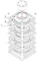
图1为本发明实施例所述的轮胎生产胎胚储存及运输装置结构示意图;1 is a schematic structural diagram of a tire production embryo storage and transportation device according to an embodiment of the present invention;
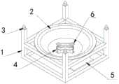
图2为本发明实施例所述的托盘结构示意图;FIG. 2 is a schematic diagram of the structure of a tray according to an embodiment of the present invention;
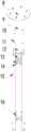
图3为本发明实施例1所述的托盘抓取组件结构示意图;3 is a schematic structural diagram of the pallet grabbing assembly according to
图4为本发明实施例1所述的托盘抓取组件剖视图;4 is a cross-sectional view of the pallet grabbing assembly according to
图5为本发明实施例1所述的卡爪杆连接座连接结构示意图;5 is a schematic diagram of the connection structure of the claw rod connection seat according to
图6为本发明实施例2所述的托盘抓取组件结构示意图;6 is a schematic structural diagram of the pallet grabbing assembly according to
图7为本发明实施例2所述的连接座内部结构示意图;7 is a schematic diagram of the internal structure of the connecting seat according to
图8为本发明实施例2所述的轮胎生产胎胚托盘抓取组件沿图7中A-A方向的剖视图;FIG. 8 is a cross-sectional view of the tire blank tray grabbing assembly according to
图9为本发明实施例2所述的转向机构结构示意图;9 is a schematic structural diagram of the steering mechanism according to
图10为本发明实施例2所述的卡爪杆张开时的转向机构状态示意图。10 is a schematic diagram of the state of the steering mechanism when the claw lever is opened according to
附图标记说明:Description of reference numbers:
1-托盘支架;2-托盘本体;3-锥形导向柱;4-定位孔;5-支撑板;6-凹槽;7-胎胚;8-连接板;9-气缸固定架;10-螺杆;11-连接轴;12-第一直线轴承;13-第一固定盘;14-卡爪杆连接座;15-卡爪杆;16-第二固定盘;17-第一气缸;18-第二气缸;19-连接块;20-卡接凸块;21-基座;22-连接座;23-转动轴;24-固定杆;25-第三固定盘;26-第三气缸;27-第三连接杆;28-导轨;29-齿条;30-齿轮;31-球轴承;32-第二直线轴承;33-旋转盘;34-导向杆;35-导向杆立柱;36-导向槽。1- Tray bracket; 2- Tray body; 3- Conical guide column; 4- Positioning hole; 5- Support plate; 6- Groove; 7- Preform; 8- Connection plate; 9- Cylinder fixing frame; 11-connecting shaft; 12-first linear bearing; 13-first fixed plate; 14-jaw rod connection seat; 15-jaw rod; 16-second fixed plate; 17-first cylinder; 18 -Second air cylinder; 19-Connecting block; 20-Clamping bump; 21-Base; 22-Connecting seat; 23-Rotating shaft; 24-Fixing rod; 25-Third fixing plate; 26-Third cylinder; 27-Third connecting rod; 28-Guide rail; 29-Rack; 30-Gear; 31-Ball bearing; 32-Second linear bearing; 33-Rotating disc; 34-Guide rod; 35-Guide rod column; 36- The guide groove.
具体实施方式Detailed ways
需要说明的是,在不冲突的情况下,本发明中的实施例及实施例中的特征可以相互组合。It should be noted that the embodiments of the present invention and the features of the embodiments may be combined with each other under the condition of no conflict.
在本发明的描述中,需要理解的是,术语“中心”、“纵向”、“横向”、“上”、“下”、“前”、“后”、“左”、“右”、“竖直”、“水平”、“顶”、“底”、“内”、“外”等指示的方位或位置关系为基于附图所示的方位或位置关系,仅是为了便于描述本发明和简化描述,而不是指示或暗示所指的装置或元件必须具有特定的方位、以特定的方位构造和操作,因此不能理解为对本发明的限制。此外,术语“第一”、“第二”等仅用于描述目的,而不能理解为指示或暗示相对重要性或者隐含指明所指示的技术特征的数量。由此,限定有“第一”、“第二”等的特征可以明示或者隐含地包括一个或者更多个该特征。在本发明的描述中,除非另有说明,“多个”的含义是两个或两个以上。In the description of the present invention, it should be understood that the terms "center", "portrait", "horizontal", "top", "bottom", "front", "rear", "left", "right", " The orientation or positional relationship indicated by vertical, horizontal, top, bottom, inner, outer, etc. is based on the orientation or positional relationship shown in the drawings, and is only for the convenience of describing the present invention and The description is simplified rather than indicating or implying that the device or element referred to must have a particular orientation, be constructed and operate in a particular orientation, and therefore should not be construed as limiting the invention. In addition, the terms "first", "second", etc. are used for descriptive purposes only, and should not be construed as indicating or implying relative importance or implying the number of indicated technical features. Thus, a feature defined as "first", "second", etc., may expressly or implicitly include one or more of that feature. In the description of the present invention, unless otherwise specified, "plurality" means two or more.
在本发明的描述中,需要说明的是,除非另有明确的规定和限定,术语“安装”、“相连”、“连接”应做广义理解,例如,可以是固定连接,也可以是可拆卸连接,或一体地连接;可以是机械连接,也可以是电连接;可以是直接相连,也可以通过中间媒介间接相连,可以是两个元件内部的连通。对于本领域的普通技术人员而言,可以通过具体情况理解上述术语在本发明中的具体含义。In the description of the present invention, it should be noted that the terms "installed", "connected" and "connected" should be understood in a broad sense, unless otherwise expressly specified and limited, for example, it may be a fixed connection or a detachable connection Connection, or integral connection; can be mechanical connection, can also be electrical connection; can be directly connected, can also be indirectly connected through an intermediate medium, can be internal communication between two elements. For those of ordinary skill in the art, the specific meanings of the above terms in the present invention can be understood through specific situations.
下面将参考附图并结合实施例来详细说明本发明。The present invention will be described in detail below with reference to the accompanying drawings and in conjunction with the embodiments.
如图1所示,一种轮胎生产胎胚储存及运输装置,包括托盘抓取组件和托盘,所述托盘上侧设有锥形导向柱3,底部与锥形导向柱3对应处设有连接孔,所述托盘中间设有定位孔4,多个所述托盘通过锥形导向柱3插入上侧相邻托盘的连接孔内叠加拼在一起,所述托盘抓取组件从托盘中间的定位孔4内向下插入,且底部卡接在其中一个托盘的定位孔4的外沿下侧。As shown in Figure 1, a tire production embryo storage and transportation device includes a pallet grabbing assembly and a pallet, the upper side of the pallet is provided with a
如图2所示,所述托盘包括托盘本体2和托盘支架1,所述托盘支架1上表面为框架结构,所述托盘本体2固定连接在托盘支架1内部且上端开口设置,且所述托盘本体2上端边缘处固定连接在托盘支架1的上表面边框上,所述托盘支架1底部位于托盘本体2正下方处设有支撑板5,所述支撑板5与托盘本体2底部对应设有定位孔4。As shown in FIG. 2 , the tray includes a
所述定位孔4包括圆形通孔,在所述圆形通孔周向边缘处向外开设有多个均匀分布的凹槽6。The
针对上述托盘结构,提出了两种托盘抓取组件与托盘相配合使用,实现轮胎生产胎胚储存及运输。In view of the above-mentioned pallet structure, two kinds of pallet grabbing components are proposed to be used together with the pallet to realize the storage and transportation of tire production embryos.
托盘抓取组件实施例1
如图3至图5所示,所述托盘抓取组件包括第一气缸17、第二气缸18,所述第一气缸17和第二气缸18均安装在气缸固定架9内,且下端的气缸杆伸出气缸固定架9底部并竖直连接有螺杆10,所述气缸固定架9底部竖直设有连接轴11,所述连接轴11上套接有第一直线轴承12,所述第一直线轴承12外侧固定连接有第一固定盘13,所述第一固定盘13固定连接在两个螺杆10底部,所述连接轴11下端固定连接有第二固定盘16,所述第一固定盘2513和第二固定盘16外侧共同活动连接有多个卡爪杆15,所述卡爪杆15下端端部向外设有卡接凸块20。As shown in FIGS. 3 to 5 , the pallet grabbing assembly includes a
所述卡爪杆15和第一固定盘13、第二固定盘16之间通过卡爪杆连接座14转动连接。The
所述卡爪杆连接座14包括基座21、连接块19,所述基座21底部固定在卡爪杆15内侧表面,前侧设有第一连接通槽,所述连接块19的一端转动连接在第一连接通槽内基座21上,另一端转动连接在第一固定盘13或第二固定盘16上。The claw
所述第一连接通槽的两侧壁之间设有柱状的第一连接杆,所述第一固定盘13和第二固定盘16周向边缘处均中心对称设有多个第二连接通槽,每个所述第二连接通槽的两侧壁之间均水平设有柱形的第二连接杆,所述连接块19的两端均设有通孔,通过通孔套接在第一连接杆和第二连接杆上。A columnar first connecting rod is arranged between the two side walls of the first connecting through groove, and a plurality of second connecting through holes are centrally symmetrically arranged at the circumferential edges of the first fixing plate 13 and the
所述气缸固定架9为上端开口设置的桶状结构,且在所述气缸固定架9的上端开口处连接有连接板8。The
在托盘抓取组件实施例1中,轮胎生产胎胚储存及运输装置的工作过程如下:In
轮胎成型车间中,成型完成的胎胚7,经输送线将装有胎胚7的托盘经输送线运输到龙门库中,龙门机械手通过托盘抓取组件将不同规格的胎胚7通过托盘分类存放,当硫化车间发出指令需要胎胚7时,托盘抓取组件中第一气缸17和第二气缸18的气缸杆伸出,气缸杆带动螺杆10、第一固定盘13、第一直线轴承12共同运动,使得第一直线轴承12沿着连接轴11下降,由于连接轴11下端通过在连接轴11的轴肩处用圆螺母和止动垫圈将第二固定盘16固定,因此气缸杆的伸出最终带动了连接块19的摆动,实现了卡爪杆15沿着连接轴11径向收缩。此时托盘抓取组件可以直接深入到托盘中,抓具直径小于最小胎胚7内径和托盘孔径并留有必要间隙,以使抓具容易插入托盘内。In the tire building workshop, the
当托盘抓取组件工作时,第一气缸17和第二气缸18的气缸杆收回,第一直线轴承12上移带动连接块19通过卡爪杆连接座14实现四个卡爪杆15张开,卡爪杆15底部的卡接凸块20与托盘定位孔4处的凹槽6切合,托盘通过和卡爪杆15相应卡接凸块20配合以确保托盘的正确方位固定,四个卡爪杆15在第一气缸17和第二气缸18收取时实现与托盘凹槽6的支撑,保证托盘在移动过程中的稳定。同时四个卡爪杆15底部与托盘紧密配合实现托盘的稳固托起。对于空托盘的叠放整理,也是按此同样的动作过程实现。When the pallet grabbing assembly works, the cylinder rods of the
托盘抓取组件实施例2
如图6至图10所示,所述托盘抓取组件包括第三气缸26,所述第三气缸26固定连接在中空结构的连接座22内部,且一端的气缸杆连接有齿条29,所述连接座22内还设有齿轮30,所述齿轮30固定连接在转动轴23上端部,且所述转动轴23下端穿出连接座22底部并转动连接在第三固定盘25中间,所述第三固定盘25的上表面连接有转向机构,所述转向机构固定连接在转动轴23上,且所述转向机构周向活动连接有多个均匀分布的卡爪杆15,所述齿条29与齿轮30相啮合,所述第三固定盘25固定连接在连接座22下方,卡爪杆15下端端部向外设有卡接凸块20。As shown in FIG. 6 to FIG. 10 , the pallet grabbing assembly includes a
所述连接座22内部的底板上侧设有导轨28,所述齿条29底部通过滑块滑动连接在导轨28上。A
所述转动轴23中间和底部均连接有第三固定盘25,两个所述第三固定盘25之间通过多个固定杆24连接在一起,且所述转动轴23中间的第三固定盘25也通过多个固定杆24与连接座22连接在一起。The middle and bottom of the rotating shaft 23 are connected with a third
所述连接座22底部外侧通过轴承座连接有球轴承31,所述球轴承31连接在转动轴23上,每个所述第三固定盘25底部也均通过轴承座连接有球轴承31,所述球轴承31连接在转动轴23上。A
所述转向机构包括旋转盘33,所述旋转盘33上周向均匀分布有多个沿径向设置的导向槽36,所述导向槽36内设有导向杆立柱35,所述导向杆立柱35的下端部转动连接有导向杆34,所述导向杆34上连接有第二直线轴承32,且外端端部通过连接块19固定连接在卡爪杆15上。The steering mechanism includes a
所述转动轴23上端在连接座22内部连接有双向推力球轴承,所述双向推力球轴承连接在固定于连接座22内的双向推力轴承固定座中,且所述转动轴23位于双向推力轴承上侧的部位连接有两个圆螺母,上端的所述圆螺母和齿轮30之间设有与双向推力轴承固定座连接的端盖。旋转轴,实际上主要承受径向力和轴向力,而轴向力主要是垂直向下的(由夹持的轮胎和托盘以及自重产生),垂直向下的轴向力通过球轴承31和上方的两个圆螺母与双向推力轴承保障固定,并且为避免工作过程中出现垂直向上窜动,齿轮和圆螺母之间增加了双向推力轴承固定座的端盖。The upper end of the rotating shaft 23 is connected with a two-way thrust ball bearing inside the connecting
在托盘抓取组件实施例2中,轮胎生产胎胚储存及运输装置的工作过程如下:In
轮胎成型车间中,成型完成的胎胚7,经输送线将装有胎胚7的托盘经输送线运输到龙门库中,龙门机械手通过托盘抓取组件将不同规格的胎胚7通过托盘分类存放,当硫化车间发出指令需要胎胚7时,托盘抓取组件中第三气缸26的气缸杆伸出,带动第三连接杆27运动,因第三连接杆27与齿条29连接,齿条29与齿轮30啮合,因此,齿条29在第三气缸26的驱动下在导轨28滑块上实现滑动,进而转动齿轮30。连接座22可以与机器人或龙门桁架机械手连接。转动轴23通过球轴承31将两个转向机构连接在一起,此时,转向机构中旋转盘33开始转动,卡爪杆15由于与导向杆34固定连接,此时通过第二直线轴承32开始实现与导向杆34垂直的导向杆立柱35在旋转盘33上的导向槽36内向轴心运动,从而实现卡爪杆15收合动作。In the tire building workshop, the
此时托盘抓取组件可以直接深入到托盘中,抓具直径小于最小胎胚7内径和托盘孔径并留有必要间隙,以使抓具容易插入托盘内。当托盘抓取组件工作时,第三气缸26中气缸杆收回带动第三连接杆27和齿条29在导轨28上实现滑动,从而转动齿轮30。同理,连接座22可以与机器人或龙门桁架机械手连接。转动轴23通过球轴承31将两个转向机构连接在一起,此时,转向机构中旋转盘33开始转动,卡爪杆15由于与导向杆34固定连接,此时通过第二直线轴承32开始实现导向杆立柱35在旋转盘33中的导向槽36内向远离轴心的方向运动,从而实现卡爪杆15张开动作。卡爪杆15尾部与托盘定位孔4处的凹槽6切合,托盘通过和卡接凸块20配合以确保托盘的正确方位固定,四个卡爪杆15通过第三气缸26收取操作实现与托盘上的凹槽6的支撑,保证胎胚7托盘的移动过程中托盘的稳定。同时四个卡爪杆15底部与托盘紧密配合实现托盘的稳固托起。对于空托盘的叠放整理,也是按此同样的动作过程实现。At this time, the pallet grabbing assembly can directly penetrate into the pallet, and the diameter of the gripper is smaller than the inner diameter of the
以上所述仅为本发明的较佳实施例而已,并不用以限制本发明,凡在本发明的精神和原则之内,所作的任何修改、等同替换、改进等,均应包含在本发明的保护范围之内。The above descriptions are only preferred embodiments of the present invention, and are not intended to limit the present invention. Any modification, equivalent replacement, improvement, etc. made within the spirit and principle of the present invention shall be included in the scope of the present invention. within the scope of protection.
Claims (10)
Priority Applications (1)
| Application Number | Priority Date | Filing Date | Title |
|---|---|---|---|
| CN202010387145.7ACN111483710A (en) | 2020-05-09 | 2020-05-09 | Tire production child embryo is stored and conveyer |
Applications Claiming Priority (1)
| Application Number | Priority Date | Filing Date | Title |
|---|---|---|---|
| CN202010387145.7ACN111483710A (en) | 2020-05-09 | 2020-05-09 | Tire production child embryo is stored and conveyer |
Publications (1)
| Publication Number | Publication Date |
|---|---|
| CN111483710Atrue CN111483710A (en) | 2020-08-04 |
Family
ID=71813292
Family Applications (1)
| Application Number | Title | Priority Date | Filing Date |
|---|---|---|---|
| CN202010387145.7APendingCN111483710A (en) | 2020-05-09 | 2020-05-09 | Tire production child embryo is stored and conveyer |
Country Status (1)
| Country | Link |
|---|---|
| CN (1) | CN111483710A (en) |
Cited By (2)
| Publication number | Priority date | Publication date | Assignee | Title |
|---|---|---|---|---|
| CN118597840A (en)* | 2024-05-26 | 2024-09-06 | 淮安市广达机械设备制造有限公司 | An intelligent control system for aisle stacking crane based on tire production line |
| CN119018623A (en)* | 2024-10-29 | 2024-11-26 | 江苏晟林科技有限公司 | Tire conveying device |
Citations (9)
| Publication number | Priority date | Publication date | Assignee | Title |
|---|---|---|---|---|
| GB175325A (en)* | 1920-09-14 | 1922-02-14 | Herbert Mcdonald Cooper | An improved lifting and dumping or ring discharge grab |
| WO1999038713A1 (en)* | 1998-01-13 | 1999-08-05 | Hjorth Hansen Arne | An installation and an auxiliary therefor for use in workshop handling of car wheels |
| KR20110054367A (en)* | 2009-11-17 | 2011-05-25 | 한국타이어 주식회사 | Gripper Device for Tire Stack |
| CN203512752U (en)* | 2013-09-25 | 2014-04-02 | 青岛科捷自动化设备有限公司 | Manipulator for transporting pile of tires |
| CN106347999A (en)* | 2016-09-23 | 2017-01-25 | 江阴职业技术学院 | Intelligent grabbing manipulator for automotive green tires |
| CN206087698U (en)* | 2016-08-31 | 2017-04-12 | 天津立中集团股份有限公司 | Compartment wheel tray |
| CN107098159A (en)* | 2017-06-24 | 2017-08-29 | 安徽海之纳科技有限公司 | A kind of new-energy automobile special tyre embryo intelligent grabbing device |
| CN208182170U (en)* | 2018-05-03 | 2018-12-04 | 江苏华安橡胶科技有限公司 | A kind of tire transhipment capture apparatus |
| CN212196813U (en)* | 2020-05-09 | 2020-12-22 | 天津机电职业技术学院 | Tire production child embryo is stored and conveyer |
- 2020
- 2020-05-09CNCN202010387145.7Apatent/CN111483710A/enactivePending
Patent Citations (9)
| Publication number | Priority date | Publication date | Assignee | Title |
|---|---|---|---|---|
| GB175325A (en)* | 1920-09-14 | 1922-02-14 | Herbert Mcdonald Cooper | An improved lifting and dumping or ring discharge grab |
| WO1999038713A1 (en)* | 1998-01-13 | 1999-08-05 | Hjorth Hansen Arne | An installation and an auxiliary therefor for use in workshop handling of car wheels |
| KR20110054367A (en)* | 2009-11-17 | 2011-05-25 | 한국타이어 주식회사 | Gripper Device for Tire Stack |
| CN203512752U (en)* | 2013-09-25 | 2014-04-02 | 青岛科捷自动化设备有限公司 | Manipulator for transporting pile of tires |
| CN206087698U (en)* | 2016-08-31 | 2017-04-12 | 天津立中集团股份有限公司 | Compartment wheel tray |
| CN106347999A (en)* | 2016-09-23 | 2017-01-25 | 江阴职业技术学院 | Intelligent grabbing manipulator for automotive green tires |
| CN107098159A (en)* | 2017-06-24 | 2017-08-29 | 安徽海之纳科技有限公司 | A kind of new-energy automobile special tyre embryo intelligent grabbing device |
| CN208182170U (en)* | 2018-05-03 | 2018-12-04 | 江苏华安橡胶科技有限公司 | A kind of tire transhipment capture apparatus |
| CN212196813U (en)* | 2020-05-09 | 2020-12-22 | 天津机电职业技术学院 | Tire production child embryo is stored and conveyer |
Non-Patent Citations (1)
| Title |
|---|
| 吕炜帅, 橡塑技术与装备, vol. 46, no. 2, 15 January 2020 (2020-01-15), pages 52 - 57* |
Cited By (3)
| Publication number | Priority date | Publication date | Assignee | Title |
|---|---|---|---|---|
| CN118597840A (en)* | 2024-05-26 | 2024-09-06 | 淮安市广达机械设备制造有限公司 | An intelligent control system for aisle stacking crane based on tire production line |
| CN118597840B (en)* | 2024-05-26 | 2025-02-18 | 上饶丫牛软件中心(个人独资) | Intelligent control system of tunnel stacker based on tire production line |
| CN119018623A (en)* | 2024-10-29 | 2024-11-26 | 江苏晟林科技有限公司 | Tire conveying device |
Similar Documents
| Publication | Publication Date | Title |
|---|---|---|
| WO2018076256A1 (en) | Motor blanking-plate stacking system | |
| CN204264978U (en) | Drum conveying mechanical arm | |
| CN108736088B (en) | Automatic battery pack disassembling system | |
| CN111483710A (en) | Tire production child embryo is stored and conveyer | |
| CN104453318A (en) | Automatic cylindrical multi-dimension parking garage | |
| CN103240734B (en) | A kind of automatic charging machinery hand | |
| CN202527381U (en) | Rotating disk type classification test machine | |
| CN103538059B (en) | Blow-molding tray grabbing robot structure | |
| CN212400128U (en) | Notebook drain pan material loading positioning device | |
| CN106272360A (en) | Multiple degrees of freedom assembling and disassembling manipulator | |
| KR101422748B1 (en) | Apparatus for loading of spare tire | |
| CN108638102A (en) | A kind of automobile tire grabbing device | |
| CN116750389A (en) | An automated stacking device | |
| CN119408051A (en) | A frame forming mold for a lithium battery tray | |
| CN116729909A (en) | High stability power battery pole CNC machining and unloading automatic stacking device | |
| CN110000655A (en) | A kind of valve pocket grinding device | |
| CN218402570U (en) | An egg tray hooking and transporting device applied to an egg tray loading and unloading device | |
| CN111976179B (en) | Multilayer multimode tire vulcanizer and production process thereof | |
| CN212196813U (en) | Tire production child embryo is stored and conveyer | |
| CN212197077U (en) | Tire production child embryo tray snatchs subassembly | |
| CN104889625B (en) | Passenger car axle is welded with stiffening ring and is used stiffening ring automatic charging device | |
| CN209682780U (en) | An automatic injection molding device | |
| CN109969776A (en) | A kind of intelligent sorting teaching robot experience system | |
| CN215749232U (en) | Rotor disc manipulator of new energy motor | |
| CN217322340U (en) | Grabbing device and tire bead feeding equipment |
Legal Events
| Date | Code | Title | Description |
|---|---|---|---|
| PB01 | Publication | ||
| PB01 | Publication | ||
| SE01 | Entry into force of request for substantive examination | ||
| SE01 | Entry into force of request for substantive examination |