CN111483306A - Heat distribution device for hybrid vehicle - Google Patents
Heat distribution device for hybrid vehicleDownload PDFInfo
- Publication number
- CN111483306A CN111483306ACN201911405209.5ACN201911405209ACN111483306ACN 111483306 ACN111483306 ACN 111483306ACN 201911405209 ACN201911405209 ACN 201911405209ACN 111483306 ACN111483306 ACN 111483306A
- Authority
- CN
- China
- Prior art keywords
- heat
- battery
- temperature
- internal combustion
- combustion engine
- Prior art date
- Legal status (The legal status is an assumption and is not a legal conclusion. Google has not performed a legal analysis and makes no representation as to the accuracy of the status listed.)
- Withdrawn
Links
Images


Classifications
- B—PERFORMING OPERATIONS; TRANSPORTING
- B60—VEHICLES IN GENERAL
- B60K—ARRANGEMENT OR MOUNTING OF PROPULSION UNITS OR OF TRANSMISSIONS IN VEHICLES; ARRANGEMENT OR MOUNTING OF PLURAL DIVERSE PRIME-MOVERS IN VEHICLES; AUXILIARY DRIVES FOR VEHICLES; INSTRUMENTATION OR DASHBOARDS FOR VEHICLES; ARRANGEMENTS IN CONNECTION WITH COOLING, AIR INTAKE, GAS EXHAUST OR FUEL SUPPLY OF PROPULSION UNITS IN VEHICLES
- B60K1/00—Arrangement or mounting of electrical propulsion units
- B—PERFORMING OPERATIONS; TRANSPORTING
- B60—VEHICLES IN GENERAL
- B60K—ARRANGEMENT OR MOUNTING OF PROPULSION UNITS OR OF TRANSMISSIONS IN VEHICLES; ARRANGEMENT OR MOUNTING OF PLURAL DIVERSE PRIME-MOVERS IN VEHICLES; AUXILIARY DRIVES FOR VEHICLES; INSTRUMENTATION OR DASHBOARDS FOR VEHICLES; ARRANGEMENTS IN CONNECTION WITH COOLING, AIR INTAKE, GAS EXHAUST OR FUEL SUPPLY OF PROPULSION UNITS IN VEHICLES
- B60K11/00—Arrangement in connection with cooling of propulsion units
- B60K11/02—Arrangement in connection with cooling of propulsion units with liquid cooling
- B—PERFORMING OPERATIONS; TRANSPORTING
- B60—VEHICLES IN GENERAL
- B60H—ARRANGEMENTS OF HEATING, COOLING, VENTILATING OR OTHER AIR-TREATING DEVICES SPECIALLY ADAPTED FOR PASSENGER OR GOODS SPACES OF VEHICLES
- B60H1/00—Heating, cooling or ventilating [HVAC] devices
- B60H1/00271—HVAC devices specially adapted for particular vehicle parts or components and being connected to the vehicle HVAC unit
- B60H1/00278—HVAC devices specially adapted for particular vehicle parts or components and being connected to the vehicle HVAC unit for the battery
- B—PERFORMING OPERATIONS; TRANSPORTING
- B60—VEHICLES IN GENERAL
- B60K—ARRANGEMENT OR MOUNTING OF PROPULSION UNITS OR OF TRANSMISSIONS IN VEHICLES; ARRANGEMENT OR MOUNTING OF PLURAL DIVERSE PRIME-MOVERS IN VEHICLES; AUXILIARY DRIVES FOR VEHICLES; INSTRUMENTATION OR DASHBOARDS FOR VEHICLES; ARRANGEMENTS IN CONNECTION WITH COOLING, AIR INTAKE, GAS EXHAUST OR FUEL SUPPLY OF PROPULSION UNITS IN VEHICLES
- B60K11/00—Arrangement in connection with cooling of propulsion units
- B60K11/02—Arrangement in connection with cooling of propulsion units with liquid cooling
- B60K11/04—Arrangement or mounting of radiators, radiator shutters, or radiator blinds
- B—PERFORMING OPERATIONS; TRANSPORTING
- B60—VEHICLES IN GENERAL
- B60L—PROPULSION OF ELECTRICALLY-PROPELLED VEHICLES; SUPPLYING ELECTRIC POWER FOR AUXILIARY EQUIPMENT OF ELECTRICALLY-PROPELLED VEHICLES; ELECTRODYNAMIC BRAKE SYSTEMS FOR VEHICLES IN GENERAL; MAGNETIC SUSPENSION OR LEVITATION FOR VEHICLES; MONITORING OPERATING VARIABLES OF ELECTRICALLY-PROPELLED VEHICLES; ELECTRIC SAFETY DEVICES FOR ELECTRICALLY-PROPELLED VEHICLES
- B60L1/00—Supplying electric power to auxiliary equipment of vehicles
- B60L1/02—Supplying electric power to auxiliary equipment of vehicles to electric heating circuits
- B—PERFORMING OPERATIONS; TRANSPORTING
- B60—VEHICLES IN GENERAL
- B60L—PROPULSION OF ELECTRICALLY-PROPELLED VEHICLES; SUPPLYING ELECTRIC POWER FOR AUXILIARY EQUIPMENT OF ELECTRICALLY-PROPELLED VEHICLES; ELECTRODYNAMIC BRAKE SYSTEMS FOR VEHICLES IN GENERAL; MAGNETIC SUSPENSION OR LEVITATION FOR VEHICLES; MONITORING OPERATING VARIABLES OF ELECTRICALLY-PROPELLED VEHICLES; ELECTRIC SAFETY DEVICES FOR ELECTRICALLY-PROPELLED VEHICLES
- B60L58/00—Methods or circuit arrangements for monitoring or controlling batteries or fuel cells, specially adapted for electric vehicles
- B60L58/10—Methods or circuit arrangements for monitoring or controlling batteries or fuel cells, specially adapted for electric vehicles for monitoring or controlling batteries
- B60L58/24—Methods or circuit arrangements for monitoring or controlling batteries or fuel cells, specially adapted for electric vehicles for monitoring or controlling batteries for controlling the temperature of batteries
- B60L58/26—Methods or circuit arrangements for monitoring or controlling batteries or fuel cells, specially adapted for electric vehicles for monitoring or controlling batteries for controlling the temperature of batteries by cooling
- B—PERFORMING OPERATIONS; TRANSPORTING
- B60—VEHICLES IN GENERAL
- B60L—PROPULSION OF ELECTRICALLY-PROPELLED VEHICLES; SUPPLYING ELECTRIC POWER FOR AUXILIARY EQUIPMENT OF ELECTRICALLY-PROPELLED VEHICLES; ELECTRODYNAMIC BRAKE SYSTEMS FOR VEHICLES IN GENERAL; MAGNETIC SUSPENSION OR LEVITATION FOR VEHICLES; MONITORING OPERATING VARIABLES OF ELECTRICALLY-PROPELLED VEHICLES; ELECTRIC SAFETY DEVICES FOR ELECTRICALLY-PROPELLED VEHICLES
- B60L58/00—Methods or circuit arrangements for monitoring or controlling batteries or fuel cells, specially adapted for electric vehicles
- B60L58/10—Methods or circuit arrangements for monitoring or controlling batteries or fuel cells, specially adapted for electric vehicles for monitoring or controlling batteries
- B60L58/24—Methods or circuit arrangements for monitoring or controlling batteries or fuel cells, specially adapted for electric vehicles for monitoring or controlling batteries for controlling the temperature of batteries
- B60L58/27—Methods or circuit arrangements for monitoring or controlling batteries or fuel cells, specially adapted for electric vehicles for monitoring or controlling batteries for controlling the temperature of batteries by heating
- B—PERFORMING OPERATIONS; TRANSPORTING
- B60—VEHICLES IN GENERAL
- B60L—PROPULSION OF ELECTRICALLY-PROPELLED VEHICLES; SUPPLYING ELECTRIC POWER FOR AUXILIARY EQUIPMENT OF ELECTRICALLY-PROPELLED VEHICLES; ELECTRODYNAMIC BRAKE SYSTEMS FOR VEHICLES IN GENERAL; MAGNETIC SUSPENSION OR LEVITATION FOR VEHICLES; MONITORING OPERATING VARIABLES OF ELECTRICALLY-PROPELLED VEHICLES; ELECTRIC SAFETY DEVICES FOR ELECTRICALLY-PROPELLED VEHICLES
- B60L7/00—Electrodynamic brake systems for vehicles in general
- B60L7/02—Dynamic electric resistor braking
- B60L7/08—Controlling the braking effect
- B—PERFORMING OPERATIONS; TRANSPORTING
- B60—VEHICLES IN GENERAL
- B60L—PROPULSION OF ELECTRICALLY-PROPELLED VEHICLES; SUPPLYING ELECTRIC POWER FOR AUXILIARY EQUIPMENT OF ELECTRICALLY-PROPELLED VEHICLES; ELECTRODYNAMIC BRAKE SYSTEMS FOR VEHICLES IN GENERAL; MAGNETIC SUSPENSION OR LEVITATION FOR VEHICLES; MONITORING OPERATING VARIABLES OF ELECTRICALLY-PROPELLED VEHICLES; ELECTRIC SAFETY DEVICES FOR ELECTRICALLY-PROPELLED VEHICLES
- B60L7/00—Electrodynamic brake systems for vehicles in general
- B60L7/10—Dynamic electric regenerative braking
- B60L7/18—Controlling the braking effect
- F—MECHANICAL ENGINEERING; LIGHTING; HEATING; WEAPONS; BLASTING
- F01—MACHINES OR ENGINES IN GENERAL; ENGINE PLANTS IN GENERAL; STEAM ENGINES
- F01P—COOLING OF MACHINES OR ENGINES IN GENERAL; COOLING OF INTERNAL-COMBUSTION ENGINES
- F01P3/00—Liquid cooling
- F01P3/20—Cooling circuits not specific to a single part of engine or machine
- F—MECHANICAL ENGINEERING; LIGHTING; HEATING; WEAPONS; BLASTING
- F01—MACHINES OR ENGINES IN GENERAL; ENGINE PLANTS IN GENERAL; STEAM ENGINES
- F01P—COOLING OF MACHINES OR ENGINES IN GENERAL; COOLING OF INTERNAL-COMBUSTION ENGINES
- F01P7/00—Controlling of coolant flow
- F01P7/14—Controlling of coolant flow the coolant being liquid
- F01P7/16—Controlling of coolant flow the coolant being liquid by thermostatic control
- F01P7/162—Controlling of coolant flow the coolant being liquid by thermostatic control by cutting in and out of pumps
- F—MECHANICAL ENGINEERING; LIGHTING; HEATING; WEAPONS; BLASTING
- F01—MACHINES OR ENGINES IN GENERAL; ENGINE PLANTS IN GENERAL; STEAM ENGINES
- F01P—COOLING OF MACHINES OR ENGINES IN GENERAL; COOLING OF INTERNAL-COMBUSTION ENGINES
- F01P7/00—Controlling of coolant flow
- F01P7/14—Controlling of coolant flow the coolant being liquid
- F01P7/16—Controlling of coolant flow the coolant being liquid by thermostatic control
- F01P7/165—Controlling of coolant flow the coolant being liquid by thermostatic control characterised by systems with two or more loops
- B—PERFORMING OPERATIONS; TRANSPORTING
- B60—VEHICLES IN GENERAL
- B60K—ARRANGEMENT OR MOUNTING OF PROPULSION UNITS OR OF TRANSMISSIONS IN VEHICLES; ARRANGEMENT OR MOUNTING OF PLURAL DIVERSE PRIME-MOVERS IN VEHICLES; AUXILIARY DRIVES FOR VEHICLES; INSTRUMENTATION OR DASHBOARDS FOR VEHICLES; ARRANGEMENTS IN CONNECTION WITH COOLING, AIR INTAKE, GAS EXHAUST OR FUEL SUPPLY OF PROPULSION UNITS IN VEHICLES
- B60K1/00—Arrangement or mounting of electrical propulsion units
- B60K2001/003—Arrangement or mounting of electrical propulsion units with means for cooling the electrical propulsion units
- B60K2001/005—Arrangement or mounting of electrical propulsion units with means for cooling the electrical propulsion units the electric storage means
- B—PERFORMING OPERATIONS; TRANSPORTING
- B60—VEHICLES IN GENERAL
- B60K—ARRANGEMENT OR MOUNTING OF PROPULSION UNITS OR OF TRANSMISSIONS IN VEHICLES; ARRANGEMENT OR MOUNTING OF PLURAL DIVERSE PRIME-MOVERS IN VEHICLES; AUXILIARY DRIVES FOR VEHICLES; INSTRUMENTATION OR DASHBOARDS FOR VEHICLES; ARRANGEMENTS IN CONNECTION WITH COOLING, AIR INTAKE, GAS EXHAUST OR FUEL SUPPLY OF PROPULSION UNITS IN VEHICLES
- B60K1/00—Arrangement or mounting of electrical propulsion units
- B60K2001/003—Arrangement or mounting of electrical propulsion units with means for cooling the electrical propulsion units
- B60K2001/006—Arrangement or mounting of electrical propulsion units with means for cooling the electrical propulsion units the electric motors
- B—PERFORMING OPERATIONS; TRANSPORTING
- B60—VEHICLES IN GENERAL
- B60L—PROPULSION OF ELECTRICALLY-PROPELLED VEHICLES; SUPPLYING ELECTRIC POWER FOR AUXILIARY EQUIPMENT OF ELECTRICALLY-PROPELLED VEHICLES; ELECTRODYNAMIC BRAKE SYSTEMS FOR VEHICLES IN GENERAL; MAGNETIC SUSPENSION OR LEVITATION FOR VEHICLES; MONITORING OPERATING VARIABLES OF ELECTRICALLY-PROPELLED VEHICLES; ELECTRIC SAFETY DEVICES FOR ELECTRICALLY-PROPELLED VEHICLES
- B60L2240/00—Control parameters of input or output; Target parameters
- B60L2240/10—Vehicle control parameters
- B60L2240/36—Temperature of vehicle components or parts
- B—PERFORMING OPERATIONS; TRANSPORTING
- B60—VEHICLES IN GENERAL
- B60L—PROPULSION OF ELECTRICALLY-PROPELLED VEHICLES; SUPPLYING ELECTRIC POWER FOR AUXILIARY EQUIPMENT OF ELECTRICALLY-PROPELLED VEHICLES; ELECTRODYNAMIC BRAKE SYSTEMS FOR VEHICLES IN GENERAL; MAGNETIC SUSPENSION OR LEVITATION FOR VEHICLES; MONITORING OPERATING VARIABLES OF ELECTRICALLY-PROPELLED VEHICLES; ELECTRIC SAFETY DEVICES FOR ELECTRICALLY-PROPELLED VEHICLES
- B60L2240/00—Control parameters of input or output; Target parameters
- B60L2240/40—Drive Train control parameters
- B60L2240/44—Drive Train control parameters related to combustion engines
- B60L2240/445—Temperature
- B—PERFORMING OPERATIONS; TRANSPORTING
- B60—VEHICLES IN GENERAL
- B60L—PROPULSION OF ELECTRICALLY-PROPELLED VEHICLES; SUPPLYING ELECTRIC POWER FOR AUXILIARY EQUIPMENT OF ELECTRICALLY-PROPELLED VEHICLES; ELECTRODYNAMIC BRAKE SYSTEMS FOR VEHICLES IN GENERAL; MAGNETIC SUSPENSION OR LEVITATION FOR VEHICLES; MONITORING OPERATING VARIABLES OF ELECTRICALLY-PROPELLED VEHICLES; ELECTRIC SAFETY DEVICES FOR ELECTRICALLY-PROPELLED VEHICLES
- B60L2240/00—Control parameters of input or output; Target parameters
- B60L2240/40—Drive Train control parameters
- B60L2240/54—Drive Train control parameters related to batteries
- B60L2240/545—Temperature
- B—PERFORMING OPERATIONS; TRANSPORTING
- B60—VEHICLES IN GENERAL
- B60L—PROPULSION OF ELECTRICALLY-PROPELLED VEHICLES; SUPPLYING ELECTRIC POWER FOR AUXILIARY EQUIPMENT OF ELECTRICALLY-PROPELLED VEHICLES; ELECTRODYNAMIC BRAKE SYSTEMS FOR VEHICLES IN GENERAL; MAGNETIC SUSPENSION OR LEVITATION FOR VEHICLES; MONITORING OPERATING VARIABLES OF ELECTRICALLY-PROPELLED VEHICLES; ELECTRIC SAFETY DEVICES FOR ELECTRICALLY-PROPELLED VEHICLES
- B60L58/00—Methods or circuit arrangements for monitoring or controlling batteries or fuel cells, specially adapted for electric vehicles
- B60L58/10—Methods or circuit arrangements for monitoring or controlling batteries or fuel cells, specially adapted for electric vehicles for monitoring or controlling batteries
- B60L58/12—Methods or circuit arrangements for monitoring or controlling batteries or fuel cells, specially adapted for electric vehicles for monitoring or controlling batteries responding to state of charge [SoC]
- F—MECHANICAL ENGINEERING; LIGHTING; HEATING; WEAPONS; BLASTING
- F01—MACHINES OR ENGINES IN GENERAL; ENGINE PLANTS IN GENERAL; STEAM ENGINES
- F01P—COOLING OF MACHINES OR ENGINES IN GENERAL; COOLING OF INTERNAL-COMBUSTION ENGINES
- F01P5/00—Pumping cooling-air or liquid coolants
- F01P5/10—Pumping liquid coolant; Arrangements of coolant pumps
- F01P2005/105—Using two or more pumps
- F—MECHANICAL ENGINEERING; LIGHTING; HEATING; WEAPONS; BLASTING
- F01—MACHINES OR ENGINES IN GENERAL; ENGINE PLANTS IN GENERAL; STEAM ENGINES
- F01P—COOLING OF MACHINES OR ENGINES IN GENERAL; COOLING OF INTERNAL-COMBUSTION ENGINES
- F01P2050/00—Applications
- F01P2050/24—Hybrid vehicles
Landscapes
- Engineering & Computer Science (AREA)
- Mechanical Engineering (AREA)
- Transportation (AREA)
- Chemical & Material Sciences (AREA)
- Combustion & Propulsion (AREA)
- Power Engineering (AREA)
- General Engineering & Computer Science (AREA)
- Sustainable Development (AREA)
- Life Sciences & Earth Sciences (AREA)
- Sustainable Energy (AREA)
- Physics & Mathematics (AREA)
- Thermal Sciences (AREA)
- Hybrid Electric Vehicles (AREA)
- Cooling, Air Intake And Gas Exhaust, And Fuel Tank Arrangements In Propulsion Units (AREA)
- Secondary Cells (AREA)
- Electric Propulsion And Braking For Vehicles (AREA)
Abstract
Description
Translated fromChinese技术领域technical field
本发明涉及一种混合动力车辆的热分配装置,其在具有内燃机与电动发电机(motor generator)的混合动力车辆中,对电动发电机中产生的热进行分配。The present invention relates to a heat distribution device for a hybrid vehicle, which distributes heat generated in a motor generator in a hybrid vehicle having an internal combustion engine and a motor generator.
背景技术Background technique
作为以往的混合动力车辆的冷却装置,例如已知有专利文献1所记载者。所述混合动力车辆包括发动机(engine)和可动力运行及再生的旋转电机(电动发电机)来作为驱动源。而且,冷却装置包括下述等部分,即:内燃机冷却回路,供用于冷却发动机的冷却液(发动机冷却液)循环;旋转电机冷却回路,供用于冷却旋转电机及其电力转换器的冷却液(旋转电机冷却液)循环;热交换器,在所述两冷却回路的冷却液之间进行热交换;切换阀,将旋转电机冷却回路切换连接到热交换器侧、或旁通(bypass)热交换器的旁通通路侧;以及散热器(radiator)及泵(pump),配置在各冷却回路中。As a cooling device for a conventional hybrid vehicle, for example, the one described in
而且,分别检测热交换器的入口及出口处的旋转电机冷却液的温度来作为入口温度Tmin及出口温度Tmout。并且,当入口温度Tmin<出口温度Tmout且入口温度Tmin>旋转电机的上限温度Tmmax成立时,为旋转电机侧从发动机侧接受热的状态,有可能造成过热,因此通过将切换阀切换到旁通通路侧,来防止旋转电机等的过热。另一方面,当所述条件不成立时,旋转电机侧未从发动机侧接受热,或者没有旋转电机等发生过热之虞,因此通过将切换阀切换到热交换器侧,促进从旋转电机侧向发动机侧的散热。Then, the temperatures of the rotating electrical machine coolant at the inlet and the outlet of the heat exchanger are detected as the inlet temperature Tmin and the outlet temperature Tmout, respectively. In addition, when the inlet temperature Tmin<outlet temperature Tmout and the inlet temperature Tmin>the upper limit temperature Tmmax of the rotating electrical machine is established, the rotating electrical machine side receives heat from the engine side, which may cause overheating. Therefore, by switching the switching valve to bypass Passage side to prevent overheating of rotating electrical machines, etc. On the other hand, when the above conditions are not satisfied, the rotating electrical machine side does not receive heat from the engine side, or there is no possibility of overheating of the rotating electrical machine or the like. Therefore, by switching the switching valve to the heat exchanger side, the transfer from the rotating electrical machine side to the engine is facilitated. side cooling.
[现有技术文献][Prior Art Literature]
[专利文献][Patent Literature]
专利文献1:日本专利特开平11-313406号公报Patent Document 1: Japanese Patent Laid-Open No. 11-313406
发明内容SUMMARY OF THE INVENTION
[发明所要解决的问题][Problems to be Solved by Invention]
所述以往的冷却装置中,基于热交换器中的旋转电机冷却液的入口温度Tmin与出口温度Tmout的关系即旋转电机与发动机的相对温度关系、或者旋转电机的温度与其上限温度的关系,来控制热交换器的实质上的工作或停止,不过是控制旋转电机与发动机之间的热交换。因此,即使存在需要旋转电机中产生的热的、发动机以外的构成零件,也无法将旋转电机的热分配给所述构成零件。In the above-mentioned conventional cooling device, based on the relationship between the inlet temperature Tmin and the outlet temperature Tmout of the rotating electrical machine coolant in the heat exchanger, that is, the relative temperature relationship between the rotating electrical machine and the engine, or the relationship between the temperature of the rotating electrical machine and its upper limit temperature. The actual operation or stop of the heat exchanger is controlled, but the heat exchange between the rotary electric machine and the engine is controlled. Therefore, even if there are components other than the engine that require the heat generated in the rotary electric machine, the heat of the rotary electric machine cannot be distributed to the components.
而且,在电池为满充电或接近满充电的状态下,即使通过旋转电机的再生运转来进行发电,也无法将其电力充至电池,必须作为热而释放(消耗)。此时,以往的冷却装置中,旋转电机中的发热被反映到热交换器的入口之前伴随有延迟,入口温度Tmin>出口温度Tmout的关系不会立即成立,因此热交换器不会工作,无法进行向发动机侧的散热。Furthermore, even if the electric power is generated by the regenerative operation of the rotating electrical machine when the battery is fully charged or nearly fully charged, the electric power cannot be charged to the battery and must be released (consumed) as heat. At this time, in the conventional cooling device, there is a delay before the heat generated in the rotating electrical machine is reflected at the inlet of the heat exchanger, and the relationship between the inlet temperature Tmin > the outlet temperature Tmout does not immediately hold, and the heat exchanger does not operate, so it is impossible to Heat dissipation to the engine side is performed.
本发明是为了解决如上所述的问题而完成,其目的在于提供一种混合动力车辆的热分配装置,能够将再生运转时在电动发电机中产生的热适当分配给车辆的构成零件,从而有效地加以利用或者释放至外部。The present invention has been made to solve the above-mentioned problems, and an object of the present invention is to provide a heat distribution device for a hybrid vehicle capable of appropriately distributing heat generated in a motor generator during regenerative operation to components of the vehicle, thereby effectively distributing heat to the components of the vehicle. be used locally or released to the outside.
[解决问题的技术手段][Technical means to solve the problem]
为了达成所述目的,技术方案1的发明是一种混合动力车辆的热分配装置,其是在具有内燃机2与电动发电机(实施方式中的(以下,在本项中相同)马达4及发电机5)的混合动力车辆中,对电动发电机中产生的热进行分配,所述电动发电机将电池31的电力转换为机械动力,或者通过再生运转来将机械动力转换为电力,并回收至电池31中,所述混合动力车辆的热分配装置包括:内燃机冷却回路3,供用于冷却内燃机2的冷却水循环;电动发电机冷却回路(MG冷却回路6),供用于冷却电动发电机的制冷剂循环,且与内燃机冷却回路3独立;热交换器7,在内燃机冷却回路3的冷却水与电动发电机冷却回路的制冷剂之间进行热交换;充电率获取部件(电流电压传感器56、电控单元(Electronic Control Unit,ECU))10),获取电池31的充电率SOC;充电判定部件(ECU10、图3的步骤2),基于所获取的电池31的充电率SOC,来判定能否进行对电池31的充电;以及控制部件(ECU10、图3的步骤4以后),在进行再生运转的情况下,但判定为能进行对电池31的充电时,执行将通过再生运转而产生的电力充电至电池31的充电控制(图3的步骤3),当判定为不能进行对电池31的充电时,执行散热控制,即,将通过再生运转所产生的热经由电动发电机冷却回路而搬送至热交换器7,通过热交换器7中的热交换而散热至内燃机冷却回路3侧。In order to achieve the above-mentioned object, the invention of
根据所述结构,供用于冷却内燃机的冷却水循环的内燃机冷却回路、与供用于冷却电动发电机的制冷剂循环的电动发电机冷却回路是彼此独立地设置,并且在热交换器中进行冷却水与制冷剂之间的热交换。而且,基于所获取的电池的充电率来判定能否进行对电池的充电。According to the above configuration, the engine cooling circuit for circulating the cooling water for cooling the internal combustion engine and the motor generator cooling circuit for circulating the refrigerant for cooling the motor generator are provided independently of each other, and the cooling water and the cooling water are combined with each other in the heat exchanger. heat exchange between refrigerants. Then, based on the acquired charging rate of the battery, it is determined whether or not the battery can be charged.
并且,在进行再生运转的情况下,当判定为能进行对电池的充电时,将通过再生运转而产生的电力充电至电池。由此,能够根据电池侧的条件,来进行通过再生运转而产生的电力的再生。Then, when the regeneration operation is performed, when it is determined that the battery can be charged, the battery is charged with the electric power generated by the regeneration operation. As a result, it is possible to perform regeneration of the electric power generated by the regeneration operation according to the conditions on the battery side.
另一方面,当判定为不能进行对电池的充电时,执行散热控制,即,将通过再生运转所产生的热经由电动发电机冷却回路而搬送至热交换器,通过热交换器中的热交换而散热至内燃机冷却回路侧。由此,在不能进行对电池的充电的情况下,将通过再生运转而产生的热散热至内燃机冷却回路侧,并适当分配给车辆的构成零件,由此,能够有效地加以利用或者释放至外部。On the other hand, when it is determined that the battery cannot be charged, heat dissipation control is executed, that is, the heat generated by the regenerative operation is transferred to the heat exchanger through the motor generator cooling circuit, and the heat exchange in the heat exchanger is performed. The heat is dissipated to the cooling circuit side of the internal combustion engine. As a result, when the battery cannot be charged, the heat generated by the regenerative operation can be radiated to the engine cooling circuit side and appropriately distributed to the components of the vehicle, so that it can be effectively used or released to the outside. .
技术方案2的发明是根据技术方案1所述的混合动力车辆的热分配装置,内燃机冷却回路3具有蓄热器用流路34,所述蓄热器用流路34设有用于贮蓄冷却水的热的蓄热器33,所述混合动力车辆的热分配装置还包括对蓄热器33的温度(蓄热器水温TWEST)进行检测的蓄热器温度检测部件(蓄热器水温传感器53),控制部件在所检测出的蓄热器33的温度为第一规定温度TREF1以下时,执行向蓄热器33的散热(图3的步骤4、步骤5)。The invention of
根据所述结构,当蓄热器的温度为第一规定温度以下时,执行向蓄热器的散热。由此,将通过再生运转而产生的热散热至低温状态的蓄热器,由此,能够有效地利用蓄热器中的蓄热。According to the above configuration, when the temperature of the heat accumulator is equal to or lower than the first predetermined temperature, heat dissipation to the heat accumulator is performed. Thereby, the heat generated by the regeneration operation is radiated to the heat accumulator in a low temperature state, whereby the heat stored in the heat accumulator can be effectively utilized.
技术方案3的发明是根据技术方案2所述的混合动力车辆的热分配装置,还包括对内燃机2的温度(发动机水温TW)进行检测的内燃机温度检测部件(发动机水温传感器51),控制部件在蓄热器的温度超过第一规定温度TREF1时,结束向蓄热器33的散热,当所检测出的内燃机2的温度为第二规定温度TREF2以下时,执行用于预热的、向内燃机2的散热(图3的步骤6、步骤7)。The invention of
根据所述结构,当蓄热器的温度超过第一规定温度时,视为向蓄热器的蓄热已完成,能够使向蓄热器的散热在适当的时机(timing)结束,而不会无端地消耗通过再生运转所产生的热。而且,当所检测出的内燃机的温度为第二规定温度以下时,执行向内燃机的散热以进行预热。由此,能够将通过再生运转所产生的热有效地用于内燃机的预热。According to the above configuration, when the temperature of the heat accumulator exceeds the first predetermined temperature, the heat storage to the heat accumulator is deemed to be completed, and the heat radiation to the heat accumulator can be terminated at an appropriate timing without The heat generated by the regenerative operation is consumed unnecessarily. Then, when the detected temperature of the internal combustion engine is equal to or lower than the second predetermined temperature, heat dissipation to the internal combustion engine is performed to perform warm-up. Thereby, the heat generated by the regeneration operation can be effectively used for warming up the internal combustion engine.
技术方案4的发明是根据技术方案3所述的混合动力车辆的热分配装置,内燃机冷却回路3具有散热器回路12,所述散热器回路12设有用于将冷却水的热释放至外部的散热器8,所述混合动力车辆的热分配装置还包括恒温器9,所述恒温器9在内燃机2的温度超过第二规定温度TREF2时,开放散热器回路12。The invention of claim 4 is the heat distribution device for a hybrid vehicle according to
根据所述结构,当内燃机的温度超过第二规定温度时,恒温器工作而开放散热器回路,由此,将冷却水送往散热器。由此,在内燃机的预热完成后,能够将通过再生运转所产生的热送往散热器,并有效地释放至外部。According to the above configuration, when the temperature of the internal combustion engine exceeds the second predetermined temperature, the thermostat operates to open the radiator circuit, thereby sending the cooling water to the radiator. Accordingly, after the warm-up of the internal combustion engine is completed, the heat generated by the regenerative operation can be sent to the radiator and efficiently released to the outside.
技术方案5的发明是根据技术方案4所述的混合动力车辆的热分配装置,还包括:电池冷却回路32,连接于内燃机冷却回路3,供用于冷却电池31的冷却水循环;以及电池温度检测部件(电池水温传感器55),检测电池31的温度(电池水温TWBAT),控制部件在内燃机2的温度超过第二规定温度TREF2后,所检测出的电池31的温度为第三规定温度TREF3以下时,开放电池冷却回路32,由此来执行用于升温的、向电池31的散热(图3的步骤9、步骤10)。The invention of
根据所述结构,在内燃机冷却回路连接有电池冷却回路,用于冷却电池的冷却水在电池冷却回路中循环。并且,在内燃机的温度超过第二规定温度后,当所检测出的电池温度为第三规定温度以下时,开放电池冷却回路,由此来执行用于升温(预热)的、向电池的散热。由此,能够将通过再生运转所产生的热有效地用于电池的升温。According to the above configuration, the battery cooling circuit is connected to the internal combustion engine cooling circuit, and the cooling water for cooling the battery circulates in the battery cooling circuit. Then, after the temperature of the internal combustion engine exceeds the second predetermined temperature, when the detected battery temperature is equal to or lower than the third predetermined temperature, the battery cooling circuit is opened, thereby performing heat dissipation to the battery for raising the temperature (preheating). Thereby, the heat generated by the regeneration operation can be effectively used to raise the temperature of the battery.
技术方案6的发明是根据技术方案5所述的混合动力车辆的热分配装置,电池冷却回路32具有散热器回路43,所述散热器回路43设有用于将冷却水的热释放至外部的电池用散热器47,控制部件在电池31的温度超过第三规定温度TREF3时,执行向电池用散热器47的散热(图3的步骤9、步骤11)。The invention of
根据所述结构,当电池的温度超过第三规定温度,而电池的升温完成时,执行向电池用散热器的散热。由此,在电池的升温完成后,能够将通过再生运转所产生的热送往电池用散热器,并有效地释放至外部。According to the above configuration, when the temperature of the battery exceeds the third predetermined temperature and the temperature rise of the battery is completed, heat dissipation to the battery heat sink is performed. As a result, after the temperature rise of the battery is completed, the heat generated by the regeneration operation can be sent to the battery radiator, and can be efficiently released to the outside.
而且,为了达成所述目的,技术方案7的发明一种混合动力车辆的热分配装置,其是在具有内燃机2与电动发电机(马达4及发电机5)的混合动力车辆中,对通过所述电动发电机的再生运转而产生的热进行分配,所述电动发电机将电池31的电力转换为机械动力,或者通过再生运转来将机械动力转换为电力,并回收至电池31中,所述混合动力车辆的热分配装置包括:内燃机冷却回路3,供用于冷却内燃机2的冷却水循环;电动发电机冷却回路(MG冷却回路6),供用于冷却电动发电机的制冷剂循环,且与内燃机冷却回路3独立;热交换器7,在内燃机冷却回路3的冷却水与电动发电机冷却回路的制冷剂之间进行热交换;以及控制部件(ECU10、图3的步骤4以后),执行散热控制,即,将通过再生运转所产生的热经由电动发电机冷却回路而搬送至热交换器7,通过热交换器7中的热交换而散热至内燃机冷却回路3侧,内燃机冷却回路3包括:主回路11,通过内燃机2,供冷却水循环;蓄热器用流路34,连接于主回路11,且设有用于贮蓄冷却水的热的蓄热器33;以及散热器回路12,连接于主回路11,且设有用于将冷却水的热释放至外部的散热器8,所述内燃机冷却回路还包括:第一开闭阀(第一流量控制阀39),用于开闭蓄热器用流路34;第二开闭阀(恒温器9),用于根据内燃机2的温度来开闭散热器回路12;以及温度检测部件(发动机水温传感器51、蓄热器水温传感器53),分别检测内燃机2的温度(发动机水温TW)及蓄热器33的温度(蓄热器水温TWEST),控制部件根据所检测出的内燃机2的温度及蓄热器33的温度来控制第一开闭阀,由此来控制向蓄热器33、内燃机2及散热器8的散热。Furthermore, in order to achieve the above-mentioned object, the invention of
所述结构中,与前述的技术方案1的情况同样,供用于冷却内燃机的冷却水循环的内燃机冷却回路、与供用于冷却电动发电机的制冷剂循环的电动发电机冷却回路是彼此独立地设置,并且在热交换器中进行冷却水与制冷剂之间的热交换。而且,内燃机冷却回路具有:主回路,通过内燃机,供冷却水循环;蓄热器用流路,连接于主回路,且设有用于贮蓄冷却水的热的蓄热器;以及散热器回路,连接于主回路,且设有用于将冷却水的热释放至外部的散热器,所述混合动力车辆的热分配装置还设有:第一开闭阀,用于开闭蓄热器用流路;以及第二开闭阀,根据内燃机的温度来开闭散热器回路。In the above configuration, as in the case of the
根据本发明,执行散热控制,即,将通过再生运转所产生的热经由电动发电机冷却回路而搬送至热交换器,通过热交换器中的热交换而散热至内燃机冷却回路侧。而且,在所述散热控制中,根据所检测出的内燃机的温度及蓄热器的温度来控制第一开闭阀,由此来控制向蓄热器、内燃机及散热器的散热。由此,不论电池的充电状态如何,均能够根据内燃机及蓄热器的实际温度来将通过再生运转所产生的热适当地分配给蓄热器、内燃机或散热器,并有效地加以利用或释放。According to the present invention, heat dissipation control is performed, that is, heat generated by the regenerative operation is transferred to the heat exchanger through the motor generator cooling circuit, and heat is radiated to the engine cooling circuit side by heat exchange in the heat exchanger. Furthermore, in the heat dissipation control, the first on-off valve is controlled based on the detected temperature of the internal combustion engine and the temperature of the heat accumulator, thereby controlling heat dissipation to the heat accumulator, the internal combustion engine, and the radiator. As a result, regardless of the state of charge of the battery, the heat generated by the regenerative operation can be appropriately distributed to the heat accumulator, the internal combustion engine, or the radiator according to the actual temperatures of the internal combustion engine and the heat accumulator, and can be effectively utilized or released. .
技术方案8的发明是根据技术方案7所述的混合动力车辆的热分配装置,控制部件在蓄热器33的温度为第一规定温度TREF1以下时,将第一开闭阀开阀,由此来进行向蓄热器33的散热(图3的步骤4、步骤5)。The invention of
根据所述结构,当蓄热器的温度为第一规定温度以下时,将第一开闭阀开阀,由此来开放蓄热器用流路,执行向蓄热器的散热。由此,能够将通过再生运转所产生的热散热至低温状态的蓄热器,从而有效地用于蓄热器中的蓄热。而且,当蓄热器的温度超过第一规定温度时,视为向蓄热器的蓄热已完成,通过将第一开闭阀闭阀而封闭蓄热器用流路,从而能够使向蓄热器的散热在适当的时机结束,而不会无端地消耗通过再生运转所产生的热。According to the above configuration, when the temperature of the heat accumulator is equal to or lower than the first predetermined temperature, the first on-off valve is opened to open the flow path for the heat accumulator, thereby performing heat radiation to the heat accumulator. Thereby, the heat generated by the regeneration operation can be radiated to the heat accumulator in a low temperature state, and can be effectively used for heat storage in the heat accumulator. Then, when the temperature of the heat accumulator exceeds the first predetermined temperature, it is considered that the heat storage in the heat accumulator is completed, and the first on-off valve is closed to close the flow path for the heat accumulator, so that the heat storage can be made to the heat accumulator. The heat dissipation of the device is completed at an appropriate timing without uselessly consuming the heat generated by the regenerative operation.
技术方案9的发明是根据技术方案8所述的混合动力车辆的热分配装置,第二开闭阀构成为,在内燃机2的温度为第二规定温度TREF2以下时维持为闭阀状态,而当内燃机2的温度超过第二规定温度TREF2时开阀。The invention of
根据所述结构,例如在向蓄热器的散热结束后,当内燃机的温度为第二规定温度以下时,第二开闭阀维持为闭阀状态而封闭散热器回路,由此,能够将通过再生运转所产生的热散热至内燃机而用于预热。而且,当内燃机的温度超过第二规定温度时,第二开闭阀开阀而开放散热器回路,由此,将冷却水送往散热器。由此,能够在内燃机的预热完成后,将通过再生运转所产生的热送往散热器,并有效地释放至外部。According to the above configuration, for example, when the temperature of the internal combustion engine is equal to or lower than the second predetermined temperature after the heat dissipation to the heat accumulator is completed, the second on-off valve is maintained in the closed state to close the radiator circuit. The heat generated by the regeneration operation is dissipated to the internal combustion engine and used for warm-up. Then, when the temperature of the internal combustion engine exceeds the second predetermined temperature, the second on-off valve is opened to open the radiator circuit, thereby sending the cooling water to the radiator. Thereby, after the warm-up of the internal combustion engine is completed, the heat generated by the regenerative operation can be sent to the radiator, and can be efficiently released to the outside.
技术方案10的发明是根据技术方案9所述的混合动力车辆的热分配装置,还包括:电池冷却回路32,连接于内燃机冷却回路3,供用于冷却电池31的冷却水循环;第三开闭阀(第二流量控制阀44),用于开闭电池冷却回路32;以及电池温度检测部件(电池水温传感器55),检测电池31的温度(电池水温TWBAT),控制部件在内燃机2的温度超过第二规定温度TREF2后,当所检测出的电池31的温度为第三规定温度TREF3以下时,将第三开闭阀开阀,由此来执行用于预热的、向电池31的散热(图3的步骤9、步骤10)。The invention of
根据所述结构,在内燃机冷却回路连接有电池冷却回路,用于冷却电池的冷却水在电池冷却回路中循环。并且,在内燃机的温度超过第二规定温度后,当电池的温度为第三规定温度以下时,将第三开闭阀开阀而开放电池冷却回路,由此来执行用于升温的、向电池的散热。由此,能够将通过再生运转所产生的热有效地用于电池的升温。According to the above configuration, the battery cooling circuit is connected to the internal combustion engine cooling circuit, and the cooling water for cooling the battery circulates in the battery cooling circuit. Then, after the temperature of the internal combustion engine exceeds the second predetermined temperature, when the temperature of the battery is equal to or lower than the third predetermined temperature, the third on-off valve is opened to open the battery cooling circuit, thereby performing a process for increasing the temperature to the battery. of heat dissipation. Thereby, the heat generated by the regeneration operation can be effectively used to raise the temperature of the battery.
技术方案11的发明是根据技术方案10所述的混合动力车辆的热分配装置,电池冷却回路32具有散热器回路43,所述散热器回路43设有用于将冷却水的热释放至外部的电池用散热器47,且所述混合动力车辆的热分配装置还包括用于朝向电池用散热器47送出冷却水的水泵(第三水泵46),控制部件在电池31的温度超过第三规定温度TREF3时,驱动水泵,由此来执行向电池用散热器47的散热(图3的步骤9、步骤11)。The invention of claim 11 is the heat distribution device of the hybrid vehicle according to
根据所述结构,当电池的温度超过第三规定温度时,通过驱动水泵来执行向电池用散热器的散热。由此,在电池的升温完成后,能够将通过再生运转所产生的热送往电池用散热器而有效地释放至外部。According to the above configuration, when the temperature of the battery exceeds the third predetermined temperature, heat dissipation to the battery radiator is performed by driving the water pump. As a result, after the temperature rise of the battery is completed, the heat generated by the regeneration operation can be sent to the battery radiator to be efficiently released to the outside.
附图说明Description of drawings
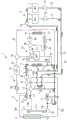
图1是示意性地表示包含本发明的一实施方式的混合动力车辆的热分配装置的冷却装置的图。FIG. 1 is a diagram schematically showing a cooling device including a heat distribution device for a hybrid vehicle according to an embodiment of the present invention.
图2是表示图1的冷却装置中的控制装置的框图。Fig. 2 is a block diagram showing a control device in the cooling device of Fig. 1 .
图3是表示由图2的控制装置所执行的热分配控制处理的流程图。FIG. 3 is a flowchart showing a heat distribution control process executed by the control device of FIG. 2 .
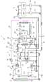
图4是用于说明向蓄热器的散热控制状态下的、冷却装置内的内燃机冷却回路的冷却水及电动发电机冷却回路的油的流动的说明图。4 is an explanatory diagram for explaining the flow of cooling water in the cooling circuit of the internal combustion engine and oil in the cooling circuit of the motor generator in the cooling device under the control state of heat dissipation to the heat accumulator.
图5是向内燃机的散热控制状态下的、与图4同样的说明图。FIG. 5 is an explanatory diagram similar to FIG. 4 in a state of control of heat radiation to the internal combustion engine.
图6是向电池的散热控制状态下的、与图4同样的说明图。FIG. 6 is an explanatory diagram similar to FIG. 4 in a state of control of heat dissipation to the battery.
图7是向散热器的散热控制状态下的、与图4同样的说明图。FIG. 7 is an explanatory diagram similar to FIG. 4 in a state of control of heat dissipation to the heat sink.
[符号的说明][Explanation of symbols]
2:内燃机2: Internal combustion engine
3:内燃机冷却回路3: Internal combustion engine cooling circuit
4:马达4: Motor
5:发电机5: Generator
6:MG冷却回路(电动发电机冷却回路)6: MG cooling circuit (motor generator cooling circuit)
7:热交换器7: Heat Exchanger
8:散热器8: Radiator
9:恒温器(第二开闭阀)9: Thermostat (second on-off valve)
10:ECU(充电判定部件、控制部件)10: ECU (charge determination part, control part)
11:主回路11: Main circuit
12:散热器回路12: Radiator circuit
31:电池31: Battery
32:电池冷却回路32: Battery cooling circuit
34:蓄热器用流路34: Flow path for heat accumulator
39:第一流量控制阀(第一开闭阀)39: The first flow control valve (the first opening and closing valve)
44:第二流量控制阀(第三开闭阀)44: Second flow control valve (third on-off valve)
43:散热器回路43: Radiator circuit
46:第三水泵(水泵)46: The third water pump (water pump)
47:电池用散热器47: Radiator for battery
51:发动机水温传感器(内燃机温度检测部件、温度检测部件)51: Engine water temperature sensor (internal combustion engine temperature detection part, temperature detection part)
53:蓄热器水温传感器(蓄热器温度检测部件、温度检测部件)53: Regenerator water temperature sensor (regenerator temperature detection part, temperature detection part)
55:电池水温传感器(电池温度检测部件)55: Battery water temperature sensor (battery temperature detection part)
56:电流电压传感器(充电率获取部件)56: Current and voltage sensor (charge rate acquisition part)
TW:发动机水温(内燃机的温度)TW: Engine water temperature (the temperature of the internal combustion engine)
TWEST:蓄热器水温(蓄热器的温度)TWEST: Regenerator water temperature (regenerator temperature)
TWBAT:电池水温(电池的温度)TWBAT: battery water temperature (battery temperature)
TREF1:第一规定温度TREF1: The first specified temperature
TREF2:第二规定温度TREF2: Second specified temperature
TREF3:第三规定温度TREF3: The third specified temperature
具体实施方式Detailed ways
以下,一边参照附图,一边详细说明本发明的优选实施方式。图1示意性地表示了包含本发明的一实施方式的热处理装置的冷却装置。如所述图1所示,所述冷却装置1适用于混合动力车辆,所述混合动力车辆包括作为驱动源而搭载的内燃机2及马达4、发电机5以及电池31。本例中,由彼此独立的马达4及发电机5构成电动发电机。Hereinafter, preferred embodiments of the present invention will be described in detail with reference to the accompanying drawings. FIG. 1 schematically shows a cooling apparatus including a heat treatment apparatus according to an embodiment of the present invention. As shown in FIG. 1 , the
冷却装置1包括下述等部分,即:内燃机冷却回路3,供用于对内燃机(以下称作“发动机”)2进行冷却等的冷却水(例如长效冷却剂(Long Life Coolant,LLC))循环;MG(马达发电机)冷却回路6,供作为用于对马达4及发电机5进行冷却等的制冷剂的油(例如自动变速箱油(Automatic Transmission Fluid,ATF))循环;热交换器7,用于在这些冷却水与油之间进行热交换;以及电池冷却回路32,供用于对电池31进行冷却等的冷却水循环。The
内燃机冷却回路3包括下述等部分,即:主回路11,可供冷却水始终循环;散热器回路12,具有散热器8,使冷却水在发动机2与散热器8之间循环;热交换器用流路13,具有热交换器7,用于使从发动机2流出至热交换器7的冷却水返回主回路11;第一三通阀14,设于热交换器用流路13,用于切换冷却水的流路;以及蓄热器用流路34,具有蓄热器33,用于将贮蓄在蓄热器33中的高温冷却水供给至主回路11。另外,散热器8被配置在混合动力车辆的前部,在其前侧设有开度可变的进气格栅(grill shutter)50(参照图2),所述进气格栅50用于向散热器8导入冷风。The internal combustion
主回路11具有第一流路11a~第三流路11c。第一流路11a连接于发动机2的水冷套(未图示)的冷却水出口,第二流路11b以连接恒温器9与电动的第一水泵16的方式而设,第三流路11c以连接第一水泵16与水冷套的冷却水入口的方式而设。第一流路11a连接于第二流路11b的中途。而且,在第一流路11a中,从发动机2侧起依序设有第二三通阀35、电动的第二水泵36、加热器37及用于车辆制暖的加热器芯38等。The main circuit 11 has a
以上述方式构成的主回路11中,当第一水泵16受到驱动时,从发动机2的冷却水出口流出的冷却水依序流经第一流路11a~第三流路11c,流入发动机2的冷却水入口而循环。In the main circuit 11 configured as described above, when the
散热器回路12具有第一流路12a~第四流路12d,并且共用主回路11的第二流路11b及第三流路11c。具体而言,第一流路12a是以连接发动机2的冷却水出口与散热器8的方式而设,第二流路12b从散热器8朝下游侧延伸。第二流路12b的下游侧分支为第三流路12c及第四流路12d,第三流路12c的下游侧端部连接于恒温器9,第四流路12d的下游侧端部连接于第一三通阀14。恒温器9构成为,在流经散热器回路12的冷却水的温度为规定温度(例如90℃)以下时,封闭散热器回路12,当超过规定温度时,开放散热器回路12。The
以上述方式构成的散热器回路12中,当第一水泵16受到驱动,并且冷却水的温度上升而超过规定温度时,恒温器9打开,由此,从发动机2流出的冷却水依序流经第一流路12a、散热器8、第二流路12b、第三流路12c、恒温器9和主回路11的第二流路11b及第三流路11c,返回发动机2而循环。由此,冷却水的热从散热器8释放至外部。另一方面,当冷却水为规定温度以下时,恒温器9维持为关闭状态,不会发生如上所述的冷却水的循环。In the
热交换器用流路13的上游侧端部连接于第一三通阀14,并通过热交换器7内而延伸,并且下游侧端部连接于主回路11的加热器芯38与水泵16之间。The upstream end of the heat
所述结构中,从发动机2经由第一三通阀14流入热交换器用流路13的冷却水通过热交换器7而流入主回路11的第一流路11a。而且,当冷却水流经热交换器7内时,如后所述,与MG冷却回路6的油之间进行热交换。In the above configuration, the cooling water flowing from the
而且,蓄热器用流路34从主回路11的较第二三通阀35为上游侧分支,并在较加热器芯38为下游侧汇流。在蓄热器用流路34中,从发动机2侧(上游侧)起依序设有用于调整冷却水的流量的第一流量控制阀39、蓄热器33及第三三通阀40。蓄热器33具有内外的双重结构,在发动机2的运转时将经升温的冷却水以隔热状态予以贮留,并且在预热运转时供给至发动机2,以促进预热。Furthermore, the
而且,MG冷却回路6具有马达用流路21、发电机用流路22、送给流路23及返回流路24。马达用流路21通向马达4,具有马达用油泵25,并且在两端部连接于送给流路23及返回流路24。发电机用流路22通向发电机5,具有发电机用油泵26,并且在两端部跟马达用流路21并联连接于送给流路23及返回流路24。Furthermore, the
送给流路23在一端侧连接马达用流路21及发电机用流路22,并且另一端侧连接于热交换器7的进油口。同样地,返回流路24在一端侧连接马达用流路21及散热器用流路22,并且另一端侧连接于热交换器7的出油口。The
以上述方式构成的MG冷却回路6中,当马达用油泵25受到驱动时,从马达4流出的油从马达用流路21流向送给流路23而流入至热交换器7,通过其内部而流出后,经由返回流路24及马达用流路21而返回马达用油泵25。同样,当发电机用油泵26受到驱动时,从发电机5流出的油从散热器用流路22流向送给流路23而流入至热交换器7,通过其内部而流出后,经由返回流路24及发电机用流路22而返回发电机用油泵26。并且,在油像这样循环时,在热交换器7中,在油与经由热交换器用流路13而流入热交换器7的冷却水之间进行热交换。In the
进而,电池冷却回路32具有主回路42及散热器回路43。主回路42从内燃机冷却回路3的主回路11的、加热器芯38的正下游侧的分支部分支,形成闭回路,并且返回主回路11的分支部的下游侧而汇流。主回路42通向电池31,具有用于对冷却水的流量进行调整的第二流量控制阀44,并且连接于蓄热器用流路34的第三三通阀40。Furthermore, the
散热器回路43以旁通电池31的方式而并联连接于主回路42的电池31的上游侧及下游侧。在散热器回路43中,从上游侧起依序设有第四三通阀45、电动的第三水泵46、电池用散热器47、直流/直流(Direct Current/Direct Current,DC/DC)转换器(converter)48及充电器49。第四三通阀45也连接于散热器回路43的充电器49的下游侧。The
以上述方式构成的电池冷却回路32中,当第二流量控制阀44开阀时,对应于其开度,冷却水从内燃机冷却回路3的主回路11流入主回路42,并通过电池31而循环。由此,根据冷却水与电池31的温度关系,通过冷却水来对电池31进行升温或冷却。而且,当第三水泵46受到驱动时,冷却水从主回路42被送出至散热器回路43。由此,冷却水的热从电池用散热器47散发至外部,并且对DC/DC转换器48及充电器49进行冷却。In the
而且,所述冷却装置中,以下述方式设有用于对各种设备的温度状态进行检测的传感器。在发动机2,设有对其冷却水出口附近的冷却水的温度(以下称作“发动机水温TW”)进行检测的发动机水温传感器51。而且,在散热器8,设有对其出口附近的冷却水的温度(以下称作“散热器水温TWR”)进行检测的散热器水温传感器52,它们的检测信号被输出至后述的ECU10(电子控制单元)(参照图2)。Moreover, the said cooling apparatus is provided with the sensor for detecting the temperature state of various equipment as follows. The
而且,在蓄热器33,设有对其出口附近的冷却水的温度(以下称作“蓄热器水温TWEST”)进行检测的蓄热器水温传感器53,在MG冷却回路6的送给流路23,设有对油的温度(以下称作“油温TATF”)进行检测的油温传感器54,在电池31,设有对其入口附近的冷却水的温度(以下称作“电池水温TWBAT”)进行检测的电池水温传感器55,它们的检测信号被输出至ECU10(参照图2)。Furthermore, the
进而,从设于电池31的电流电压传感器56,将表示流经电池31的电流/电压的检测信号输入至ECU10。ECU10基于这些检测信号来算出电池31的实际的充电率SOC。Furthermore, from the current-
ECU10包含微计算机(micro computer),所述微计算机包含中央处理器(CentralProcessing Unit,CPU)、随机存取存储器(Random Access Memory,RAM)、只读存储器(Read-Only Memory,ROM)及输入/输出接口(Input/Output interface)(均未图示)等。ECU10根据所述各种温度传感器51~55的检测信号等,来控制所述冷却装置1的各种设备(第一水泵16、第二水泵36、第三水泵46、马达用油泵25及发电机用油泵26、第一流量控制阀39及第二流量控制阀44、第一三通阀14、第二三通阀35、第三三通阀40、第四三通阀45、进气格栅50等),由此来控制冷却装置1。The
而且,ECU10在本实施方式中,尤其是通过控制图2所示的设备等,从而执行对在再生运转时由发电机5产生的热进行分配的热分配控制处理。Furthermore, in the present embodiment, the
图3表示所述热分配控制处理。本处理例如是以规定的周期来反复执行。首先,在其步骤1(图示为“S1”,以下相同)中,判别再生运转标记F_REG是否为“1”。所述再生运转标记F_REG在停止发动机2的车辆减速时执行借助发电机5的再生运转时被设置为“1”。当所述步骤1的回答为否(NO),并非再生运转中时,直接结束本处理。FIG. 3 shows the heat distribution control process. This process is repeatedly executed at a predetermined cycle, for example. First, in its step 1 (shown as "S1", the same applies hereinafter), it is determined whether or not the regeneration operation flag F_REG is "1". The regeneration operation flag F_REG is set to "1" when the regeneration operation by the
当步骤1的回答为是(YES),为再生运转中时,判别电池31的充电率SOC是否为规定值SREF以上(步骤2)。所述规定值SREF例如被设定为相当于电池31的满充电状态(例如90%)。当其回答为否而SOC<SREF时,视为能进行对电池31的充电,执行将通过再生运转所产生的电力充电至电池31的充电控制(步骤3),结束本处理。通过所述充电控制,能够根据电池31的充电率SOC来进行通过再生运转所产生的电力的再生。When the answer of
当所述步骤3的回答为是而SOC≧SREF时,视为不能进行对电池31的充电,在接下来的步骤4以后,执行将通过再生运转所产生的热分配/散热至冷却装置1的适当设备的热分配控制。首先,在步骤4中,判别所检测出的蓄热器水温TWEST是否为第一规定温度TREF1(例如90℃)以下。If the answer to Step 3 is yes and SOC≧SREF, it is considered that the
当其回答为是而TWEST≦TREF1时,视为蓄热器33中的蓄热不够充分,为了促进蓄热而执行向蓄热器33的散热控制(步骤5),结束本处理。在所述蓄热器散热控制中,在第一水泵16或马达用油泵25及发电机用油泵26正在工作的状态下,将第一流量控制阀39开阀,将第二流量控制阀44闭阀。图4表示所述蓄热器散热控制状态下的冷却水及油的流动。另外,图4及后述的图5~图7中,用粗线来表示有冷却水或油流动的流路,用箭头来表示其流动方向,并且用细线来表示无冷却水或油流动的流路。When the answer is yes and TWEST≦TREF1, it is considered that the heat storage in the
如图4所示,在所述控制状态下,通过马达用油泵25及发电机用油泵26工作,MG冷却回路6的油从马达4及发电机5侧流向送给流路23而流入热交换器7,并通过其内部而流出后,经由返回流路24而返回马达4及发电机5。As shown in FIG. 4 , in the above-described control state, the
另一方面,通过第一水泵16工作,内燃机冷却回路3的冷却水从发动机2经由主回路11而循环。而且,冷却水从发动机2经由热交换器用流路13而流入热交换器7,在通过与高温的油的热交换而经升温后,从热交换器7流出而返回发动机2。On the other hand, the cooling water of the internal combustion
而且,通过第一流量控制阀39处于开阀状态,经升温的冷却水从发动机2经由蓄热器用流路34而流入蓄热器33。由此,在蓄热器散热控制中,能够将通过再生运转所产生的热散热至低温状态的蓄热器33,从而有效地用于蓄热器33中的蓄热。Then, when the first
返回图3,当所述步骤4的回答为否而TWEST>TREF1时,视为蓄热器33已充分蓄热,前进至步骤6,判别发动机水温TW是否为第二规定温度TREF2以下。所述第二规定温度TREF2例如被设定为相当于恒温器9的工作温度的规定值(例如90℃)。Returning to FIG. 3 , when the answer to step 4 is NO and TWEST>TREF1, it is considered that the
当所述步骤6的回答为是而TW≦TREF2时,视为恒温器9未工作,并且发动机2的预热未完成,执行向发动机2的散热控制(步骤7),结束本处理。When the answer in
所述发动机散热控制中,从所述蓄热器散热控制状态,将第一流量控制阀39闭阀。如图5所示,在所述控制状态下,与蓄热器散热控制的情况同样,在热交换器7中进行冷却水与油的热交换,冷却水受到升温。而且,通过第一流量控制阀39处于闭阀状态,经升温的冷却水不会从发动机2流入蓄热器33,而是经由主回路11来循环。由此,在发动机散热控制中,能够将通过再生运转所产生的热散热至发动机2,从而有效地用于其预热。In the engine heat radiation control, the first
返回图3,当所述步骤6的回答为否而TW>TREF2时,视为发动机2的预热完成,并且恒温器9正在工作,为了促进借助散热器8的散热,将进气格栅50控制为全开状态(步骤8)。而且,判别电池水温TWBAT是否为第三规定温度TREF3以下(步骤9)。所述第三规定温度TREF3例如被设定为比电池31的上限温度低的规定值(例如30℃)。Returning to FIG. 3 , when the answer to step 6 is no and TW>TREF2, it is considered that the preheating of the
当所述步骤9的回答为是而TWBAT≦TREF3时,视为电池31处于低温状态,为了促进电池31的升温(预热)而执行向电池31的散热控制(步骤10),结束本处理。When the answer to Step 9 is YES and TWBAT≦TREF3, it is considered that the
在所述电池散热控制中,从所述发动机散热控制状态,将第二流量控制阀44开阀。如图6所示,在所述控制状态下,伴随恒温器9的工作,冷却水流经散热器回路12,由此,冷却水的热从散热器8释放至外部。从所述散热器8进行的散热通过全开状态的进气格栅50而得到促进。而且,通过第二流量控制阀44处于开阀状态,通过热交换器7中的热交换而经升温的冷却水流向电池冷却回路32的主回路42,并流入电池31。由此,在电池散热控制中,能够将通过再生运转所产生的热散热至电池31,从而有效地用于电池31的升温。In the battery heat dissipation control, the second
另一方面,当所述步骤9的回答为是而TWBAT>TREF3时,视为电池31的升温已完成,执行向电池用散热器47的散热控制(步骤11),结束本处理。On the other hand, when the answer in
在,在所述散热器散热控制中,从所述电池散热控制状态,驱动第三水泵46。由此,如图7所示,电池冷却回路32内的冷却水被送往电池用散热器47。如上所述,在散热器散热控制中,当电池31的升温完成后,能够将通过再生运转所产生的热散热至电池用散热器47,从而有效地释放至外部。In the radiator heat dissipation control, the
另外,本发明并不限定于所说明的实施方式,能够以各种实施例来实施。例如,实施方式中,当电池31的充电率SOC为规定值SREF以上这一条件成立时,视为电池31处于满充电状态而不能充电,执行散热控制。本发明在并未设定如上所述的条件,例如在电池31并非满充电状态的情况下,也能执行散热控制,由此,能够积极地利用通过再生运转所产生的热,以进行蓄热器中的蓄热或内燃机的预热等。In addition, this invention is not limited to the embodiment described, It can implement in various Example. For example, in the embodiment, when the condition that the charging rate SOC of the
而且,实施方式中,作为需要通过再生运转所产生的热的设备,是将蓄热器33或发动机2、电池31作为对象,作为用于将通过再生运转所产生的热释放至外部的设备,是将发动机用的散热器8或电池用散热器47作为对象,来对这些设备进行散热,但并不限于此,也可将需要热或者释放热的其他适当的设备作为对象。Furthermore, in the embodiment, the
而且,实施方式中,作为代表蓄热器33或发动机2、电池31的温度,使用了各设备中的冷却水的温度,但并不限于此,也可使用各设备的本体的温度。而且,马达4与发电机5是彼此独立地构成,但当然也可为一体。进而,图1等所示的冷却装置1的结构不过是例示,能在本发明的主旨范围内变更其细节结构。Furthermore, in the embodiment, the temperature of the cooling water in each device is used as the temperature of the
Claims (11)
Translated fromChineseApplications Claiming Priority (2)
| Application Number | Priority Date | Filing Date | Title |
|---|---|---|---|
| JP2019011882AJP7111635B2 (en) | 2019-01-28 | 2019-01-28 | Heat distribution device for hybrid vehicle |
| JP2019-011882 | 2019-01-28 |
Publications (1)
| Publication Number | Publication Date |
|---|---|
| CN111483306Atrue CN111483306A (en) | 2020-08-04 |
Family
ID=71733332
Family Applications (1)
| Application Number | Title | Priority Date | Filing Date |
|---|---|---|---|
| CN201911405209.5AWithdrawnCN111483306A (en) | 2019-01-28 | 2019-12-31 | Heat distribution device for hybrid vehicle |
Country Status (3)
| Country | Link |
|---|---|
| US (2) | US11186165B2 (en) |
| JP (1) | JP7111635B2 (en) |
| CN (1) | CN111483306A (en) |
Cited By (5)
| Publication number | Priority date | Publication date | Assignee | Title |
|---|---|---|---|---|
| CN112377349A (en)* | 2020-11-17 | 2021-02-19 | 无锡职业技术学院 | Bidirectional preheating device and preheating method based on hybrid electric vehicle |
| CN113547895A (en)* | 2021-08-18 | 2021-10-26 | 安徽江淮汽车集团股份有限公司 | An extended-range vehicle waste heat recovery system |
| CN114248929A (en)* | 2020-09-25 | 2022-03-29 | 本田技研工业株式会社 | Propulsion system |
| CN115246314A (en)* | 2021-04-28 | 2022-10-28 | 本田技研工业株式会社 | Vehicle with a steering wheel |
| WO2024066110A1 (en)* | 2022-09-26 | 2024-04-04 | 潍柴动力股份有限公司 | Thermal management system control method for hybrid vehicle, and hybrid vehicle |
Families Citing this family (13)
| Publication number | Priority date | Publication date | Assignee | Title |
|---|---|---|---|---|
| KR102673161B1 (en)* | 2019-02-25 | 2024-06-10 | 현대자동차주식회사 | Cooling system for temperature regulation and Method thereof |
| JP2020179805A (en)* | 2019-04-26 | 2020-11-05 | 株式会社デンソー | Vehicular heat management device, vehicular heat management system, vehicular heat management method, and control program |
| CN114060288B (en)* | 2020-08-07 | 2023-09-08 | 汉宇集团股份有限公司 | Electric pump for electric vehicle power supply thermal management system |
| CN114435115B (en)* | 2020-11-06 | 2024-03-08 | 上海汽车集团股份有限公司 | Hybrid electric vehicle and thermal management system thereof |
| US12005976B2 (en)* | 2020-11-12 | 2024-06-11 | Electrocamion Inc. | Hybrid tractor truck |
| DE102021206117A1 (en)* | 2021-06-16 | 2022-12-22 | Zf Friedrichshafen Ag | Traction drive with a cooling system with two cooling circuits |
| CN114954136B (en)* | 2021-07-23 | 2024-10-15 | 长城汽车股份有限公司 | Cooling waterway architecture of electric drive system and battery system and vehicle |
| CN113580906B (en)* | 2021-08-31 | 2024-05-14 | 重庆长安汽车股份有限公司 | Low-temperature cooling system of hybrid electric vehicle and hybrid electric vehicle |
| CN114590239B (en)* | 2022-02-25 | 2024-07-09 | 武汉理工大学 | Hybrid vehicle thermal management system control method, device and storage medium |
| CN114523816B (en)* | 2022-03-10 | 2022-11-11 | 江西新电汽车空调系统有限公司 | Integrated vehicle heat pump air conditioner and heat management system and control method thereof |
| JP7523487B2 (en)* | 2022-03-31 | 2024-07-26 | 本田技研工業株式会社 | Temperature control device and vehicle |
| CN115217605B (en)* | 2022-06-09 | 2023-12-19 | 东风汽车集团股份有限公司 | Thermal management method and system |
| DE102023206722A1 (en)* | 2023-07-14 | 2025-01-16 | Zf Friedrichshafen Ag | thermal management system and at least partially electrically powered vehicle |
Citations (11)
| Publication number | Priority date | Publication date | Assignee | Title |
|---|---|---|---|---|
| US5291960A (en)* | 1992-11-30 | 1994-03-08 | Ford Motor Company | Hybrid electric vehicle regenerative braking energy recovery system |
| JPH06319205A (en)* | 1993-04-30 | 1994-11-15 | Aqueous Res:Kk | Hybrid vehicle |
| US5809944A (en)* | 1996-08-30 | 1998-09-22 | Denso Corporation | Cooling water control valve and cooling water circuit system employing the same |
| JP2005130629A (en)* | 2003-10-24 | 2005-05-19 | Toyota Motor Corp | Automobile |
| JP2007069829A (en)* | 2005-09-08 | 2007-03-22 | Toyota Motor Corp | Vehicle cooling device |
| JP2008106613A (en)* | 2006-10-23 | 2008-05-08 | Toyota Motor Corp | Drive source warm-up device |
| JP2009180103A (en)* | 2008-01-29 | 2009-08-13 | Toyota Motor Corp | Coolant circulation device |
| JP2010151105A (en)* | 2008-12-26 | 2010-07-08 | Toyota Motor Corp | Heat-accumulation device for vehicle |
| CN101987580A (en)* | 2009-08-04 | 2011-03-23 | 铃木株式会社 | Motor-driven vehicle |
| CN103003544A (en)* | 2010-07-07 | 2013-03-27 | 标致·雪铁龙汽车公司 | Installation for cooling the drivetrain of a hybrid vehicle |
| WO2013054831A1 (en)* | 2011-10-12 | 2013-04-18 | 日産自動車株式会社 | Electric vehicle |
Family Cites Families (8)
| Publication number | Priority date | Publication date | Assignee | Title |
|---|---|---|---|---|
| DE4344368C1 (en)* | 1993-12-24 | 1995-05-11 | Daimler Benz Ag | Charge information system for an electrical or hybrid vehicle |
| JPH11313406A (en) | 1998-04-28 | 1999-11-09 | Hitachi Ltd | Hybrid vehicle cooling system |
| US8026698B2 (en)* | 2006-02-09 | 2011-09-27 | Scheucher Karl F | Scalable intelligent power supply system and method |
| US8608255B2 (en)* | 2006-04-14 | 2013-12-17 | Toyota Jidosha Kabushiki Kaisha | Vehicle and control method of vehicle |
| JP6032216B2 (en)* | 2014-01-14 | 2016-11-24 | 株式会社デンソー | Hybrid vehicle control device |
| JP6507625B2 (en)* | 2014-12-19 | 2019-05-08 | 株式会社デンソー | Control device of hybrid car |
| JP6315622B2 (en)* | 2016-03-04 | 2018-04-25 | 本田技研工業株式会社 | vehicle |
| US11084398B2 (en)* | 2018-01-15 | 2021-08-10 | Ford Global Technologies, Llc | Method of operating thermal management system in electric vehicles |
- 2019
- 2019-01-28JPJP2019011882Apatent/JP7111635B2/enactiveActive
- 2019-12-31CNCN201911405209.5Apatent/CN111483306A/ennot_activeWithdrawn
- 2020
- 2020-01-19USUS16/746,950patent/US11186165B2/enactiveActive
- 2021
- 2021-10-20USUS17/506,621patent/US20220041047A1/ennot_activeAbandoned
Patent Citations (11)
| Publication number | Priority date | Publication date | Assignee | Title |
|---|---|---|---|---|
| US5291960A (en)* | 1992-11-30 | 1994-03-08 | Ford Motor Company | Hybrid electric vehicle regenerative braking energy recovery system |
| JPH06319205A (en)* | 1993-04-30 | 1994-11-15 | Aqueous Res:Kk | Hybrid vehicle |
| US5809944A (en)* | 1996-08-30 | 1998-09-22 | Denso Corporation | Cooling water control valve and cooling water circuit system employing the same |
| JP2005130629A (en)* | 2003-10-24 | 2005-05-19 | Toyota Motor Corp | Automobile |
| JP2007069829A (en)* | 2005-09-08 | 2007-03-22 | Toyota Motor Corp | Vehicle cooling device |
| JP2008106613A (en)* | 2006-10-23 | 2008-05-08 | Toyota Motor Corp | Drive source warm-up device |
| JP2009180103A (en)* | 2008-01-29 | 2009-08-13 | Toyota Motor Corp | Coolant circulation device |
| JP2010151105A (en)* | 2008-12-26 | 2010-07-08 | Toyota Motor Corp | Heat-accumulation device for vehicle |
| CN101987580A (en)* | 2009-08-04 | 2011-03-23 | 铃木株式会社 | Motor-driven vehicle |
| CN103003544A (en)* | 2010-07-07 | 2013-03-27 | 标致·雪铁龙汽车公司 | Installation for cooling the drivetrain of a hybrid vehicle |
| WO2013054831A1 (en)* | 2011-10-12 | 2013-04-18 | 日産自動車株式会社 | Electric vehicle |
Cited By (6)
| Publication number | Priority date | Publication date | Assignee | Title |
|---|---|---|---|---|
| CN114248929A (en)* | 2020-09-25 | 2022-03-29 | 本田技研工业株式会社 | Propulsion system |
| CN112377349A (en)* | 2020-11-17 | 2021-02-19 | 无锡职业技术学院 | Bidirectional preheating device and preheating method based on hybrid electric vehicle |
| CN115246314A (en)* | 2021-04-28 | 2022-10-28 | 本田技研工业株式会社 | Vehicle with a steering wheel |
| CN113547895A (en)* | 2021-08-18 | 2021-10-26 | 安徽江淮汽车集团股份有限公司 | An extended-range vehicle waste heat recovery system |
| CN113547895B (en)* | 2021-08-18 | 2023-02-17 | 安徽江淮汽车集团股份有限公司 | Range-extending type automobile waste heat recovery system |
| WO2024066110A1 (en)* | 2022-09-26 | 2024-04-04 | 潍柴动力股份有限公司 | Thermal management system control method for hybrid vehicle, and hybrid vehicle |
Also Published As
| Publication number | Publication date |
|---|---|
| JP2020117167A (en) | 2020-08-06 |
| US20200238818A1 (en) | 2020-07-30 |
| JP7111635B2 (en) | 2022-08-02 |
| US11186165B2 (en) | 2021-11-30 |
| US20220041047A1 (en) | 2022-02-10 |
Similar Documents
| Publication | Publication Date | Title |
|---|---|---|
| CN111483306A (en) | Heat distribution device for hybrid vehicle | |
| CN111605438B (en) | Battery heating device for hybrid vehicles | |
| CN111613853B (en) | Battery heating device | |
| US10829005B2 (en) | Vehicular heat exchange device | |
| JP5945768B2 (en) | Waste heat management system and management method for electric vehicle | |
| CN106183786B (en) | Cooling circulation system for hybrid power system and automobile | |
| US9482142B2 (en) | Cooling system for an electric vehicle and method for producing a cooling system | |
| CN104640736B (en) | electric vehicle | |
| US20200003320A1 (en) | Thermal management system for vehicle | |
| JP2013095409A (en) | Battery warm-up apparatus and battery warm-up method | |
| US20120014680A1 (en) | Electrical heating device | |
| JP2003514183A (en) | Method and apparatus for transporting thermal energy generated in automobiles | |
| JP2008290636A (en) | Hybrid car | |
| CN112440706A (en) | Vehicle with a steering wheel | |
| CN108859735B (en) | Cooling system and cooling method for hybrid vehicle | |
| CN113226832A (en) | Vehicle with a steering wheel | |
| KR101936474B1 (en) | Method and Dual Cooling System using Engine Coolant Pre-Heating and Eco Vehicle thereby | |
| US9863303B2 (en) | Cooling water control apparatus | |
| CN115602875A (en) | Fuel cell cooling system | |
| WO2021024947A1 (en) | Motor unit, temperature regulation system, and vehicle | |
| JP3889396B2 (en) | Hybrid vehicle cooling system | |
| CN110077223A (en) | The cooling device of vehicle | |
| KR102600061B1 (en) | Cooling system for electric vehicle | |
| CN112350517A (en) | Motor unit, temperature control system, and vehicle | |
| JP2022505808A (en) | Power converter device |
Legal Events
| Date | Code | Title | Description |
|---|---|---|---|
| PB01 | Publication | ||
| PB01 | Publication | ||
| SE01 | Entry into force of request for substantive examination | ||
| SE01 | Entry into force of request for substantive examination | ||
| WW01 | Invention patent application withdrawn after publication | ||
| WW01 | Invention patent application withdrawn after publication | Application publication date:20200804 |