CN111481117B - Eliminate robots that detect dead spots - Google Patents
Eliminate robots that detect dead spotsDownload PDFInfo
- Publication number
- CN111481117B CN111481117BCN201911012140.XACN201911012140ACN111481117BCN 111481117 BCN111481117 BCN 111481117BCN 201911012140 ACN201911012140 ACN 201911012140ACN 111481117 BCN111481117 BCN 111481117B
- Authority
- CN
- China
- Prior art keywords
- light
- segment
- image
- image frame
- light source
- Prior art date
- Legal status (The legal status is an assumption and is not a legal conclusion. Google has not performed a legal analysis and makes no representation as to the accuracy of the status listed.)
- Active
Links
Images


Classifications
- G—PHYSICS
- G05—CONTROLLING; REGULATING
- G05D—SYSTEMS FOR CONTROLLING OR REGULATING NON-ELECTRIC VARIABLES
- G05D1/00—Control of position, course, altitude or attitude of land, water, air or space vehicles, e.g. using automatic pilots
- G05D1/02—Control of position or course in two dimensions
- G05D1/021—Control of position or course in two dimensions specially adapted to land vehicles
- G05D1/0231—Control of position or course in two dimensions specially adapted to land vehicles using optical position detecting means
- G05D1/0246—Control of position or course in two dimensions specially adapted to land vehicles using optical position detecting means using a video camera in combination with image processing means
- G05D1/0248—Control of position or course in two dimensions specially adapted to land vehicles using optical position detecting means using a video camera in combination with image processing means in combination with a laser
- A—HUMAN NECESSITIES
- A47—FURNITURE; DOMESTIC ARTICLES OR APPLIANCES; COFFEE MILLS; SPICE MILLS; SUCTION CLEANERS IN GENERAL
- A47L—DOMESTIC WASHING OR CLEANING; SUCTION CLEANERS IN GENERAL
- A47L11/00—Machines for cleaning floors, carpets, furniture, walls, or wall coverings
- A—HUMAN NECESSITIES
- A47—FURNITURE; DOMESTIC ARTICLES OR APPLIANCES; COFFEE MILLS; SPICE MILLS; SUCTION CLEANERS IN GENERAL
- A47L—DOMESTIC WASHING OR CLEANING; SUCTION CLEANERS IN GENERAL
- A47L9/00—Details or accessories of suction cleaners, e.g. mechanical means for controlling the suction or for effecting pulsating action; Storing devices specially adapted to suction cleaners or parts thereof; Carrying-vehicles specially adapted for suction cleaners
- A47L9/28—Installation of the electric equipment, e.g. adaptation or attachment to the suction cleaner; Controlling suction cleaners by electric means
- A47L9/30—Arrangement of illuminating devices
- A—HUMAN NECESSITIES
- A47—FURNITURE; DOMESTIC ARTICLES OR APPLIANCES; COFFEE MILLS; SPICE MILLS; SUCTION CLEANERS IN GENERAL
- A47L—DOMESTIC WASHING OR CLEANING; SUCTION CLEANERS IN GENERAL
- A47L11/00—Machines for cleaning floors, carpets, furniture, walls, or wall coverings
- A47L11/40—Parts or details of machines not provided for in groups A47L11/02 - A47L11/38, or not restricted to one of these groups, e.g. handles, arrangements of switches, skirts, buffers, levers
- A47L11/4011—Regulation of the cleaning machine by electric means; Control systems and remote control systems therefor
- A—HUMAN NECESSITIES
- A47—FURNITURE; DOMESTIC ARTICLES OR APPLIANCES; COFFEE MILLS; SPICE MILLS; SUCTION CLEANERS IN GENERAL
- A47L—DOMESTIC WASHING OR CLEANING; SUCTION CLEANERS IN GENERAL
- A47L11/00—Machines for cleaning floors, carpets, furniture, walls, or wall coverings
- A47L11/40—Parts or details of machines not provided for in groups A47L11/02 - A47L11/38, or not restricted to one of these groups, e.g. handles, arrangements of switches, skirts, buffers, levers
- A47L11/4061—Steering means; Means for avoiding obstacles; Details related to the place where the driver is accommodated
- B—PERFORMING OPERATIONS; TRANSPORTING
- B25—HAND TOOLS; PORTABLE POWER-DRIVEN TOOLS; MANIPULATORS
- B25J—MANIPULATORS; CHAMBERS PROVIDED WITH MANIPULATION DEVICES
- B25J11/00—Manipulators not otherwise provided for
- B25J11/008—Manipulators for service tasks
- B25J11/0085—Cleaning
- G—PHYSICS
- G01—MEASURING; TESTING
- G01S—RADIO DIRECTION-FINDING; RADIO NAVIGATION; DETERMINING DISTANCE OR VELOCITY BY USE OF RADIO WAVES; LOCATING OR PRESENCE-DETECTING BY USE OF THE REFLECTION OR RERADIATION OF RADIO WAVES; ANALOGOUS ARRANGEMENTS USING OTHER WAVES
- G01S11/00—Systems for determining distance or velocity not using reflection or reradiation
- G01S11/12—Systems for determining distance or velocity not using reflection or reradiation using electromagnetic waves other than radio waves
- G—PHYSICS
- G05—CONTROLLING; REGULATING
- G05D—SYSTEMS FOR CONTROLLING OR REGULATING NON-ELECTRIC VARIABLES
- G05D1/00—Control of position, course, altitude or attitude of land, water, air or space vehicles, e.g. using automatic pilots
- G05D1/02—Control of position or course in two dimensions
- G05D1/021—Control of position or course in two dimensions specially adapted to land vehicles
- G05D1/0231—Control of position or course in two dimensions specially adapted to land vehicles using optical position detecting means
- G05D1/0242—Control of position or course in two dimensions specially adapted to land vehicles using optical position detecting means using non-visible light signals, e.g. IR or UV signals
- G—PHYSICS
- G05—CONTROLLING; REGULATING
- G05D—SYSTEMS FOR CONTROLLING OR REGULATING NON-ELECTRIC VARIABLES
- G05D1/00—Control of position, course, altitude or attitude of land, water, air or space vehicles, e.g. using automatic pilots
- G05D1/20—Control system inputs
- G05D1/24—Arrangements for determining position or orientation
- G05D1/247—Arrangements for determining position or orientation using signals provided by artificial sources external to the vehicle, e.g. navigation beacons
- G—PHYSICS
- G05—CONTROLLING; REGULATING
- G05D—SYSTEMS FOR CONTROLLING OR REGULATING NON-ELECTRIC VARIABLES
- G05D1/00—Control of position, course, altitude or attitude of land, water, air or space vehicles, e.g. using automatic pilots
- G05D1/60—Intended control result
- G05D1/617—Safety or protection, e.g. defining protection zones around obstacles or avoiding hazards
- G05D1/622—Obstacle avoidance
- G—PHYSICS
- G05—CONTROLLING; REGULATING
- G05D—SYSTEMS FOR CONTROLLING OR REGULATING NON-ELECTRIC VARIABLES
- G05D1/00—Control of position, course, altitude or attitude of land, water, air or space vehicles, e.g. using automatic pilots
- G05D1/60—Intended control result
- G05D1/648—Performing a task within a working area or space, e.g. cleaning
- G—PHYSICS
- G06—COMPUTING OR CALCULATING; COUNTING
- G06T—IMAGE DATA PROCESSING OR GENERATION, IN GENERAL
- G06T7/00—Image analysis
- G06T7/50—Depth or shape recovery
- G06T7/521—Depth or shape recovery from laser ranging, e.g. using interferometry; from the projection of structured light
- A—HUMAN NECESSITIES
- A47—FURNITURE; DOMESTIC ARTICLES OR APPLIANCES; COFFEE MILLS; SPICE MILLS; SUCTION CLEANERS IN GENERAL
- A47L—DOMESTIC WASHING OR CLEANING; SUCTION CLEANERS IN GENERAL
- A47L2201/00—Robotic cleaning machines, i.e. with automatic control of the travelling movement or the cleaning operation
- A47L2201/04—Automatic control of the travelling movement; Automatic obstacle detection
- A—HUMAN NECESSITIES
- A47—FURNITURE; DOMESTIC ARTICLES OR APPLIANCES; COFFEE MILLS; SPICE MILLS; SUCTION CLEANERS IN GENERAL
- A47L—DOMESTIC WASHING OR CLEANING; SUCTION CLEANERS IN GENERAL
- A47L2201/00—Robotic cleaning machines, i.e. with automatic control of the travelling movement or the cleaning operation
- A47L2201/06—Control of the cleaning action for autonomous devices; Automatic detection of the surface condition before, during or after cleaning
Landscapes
- Engineering & Computer Science (AREA)
- Physics & Mathematics (AREA)
- General Physics & Mathematics (AREA)
- Radar, Positioning & Navigation (AREA)
- Remote Sensing (AREA)
- Aviation & Aerospace Engineering (AREA)
- Automation & Control Theory (AREA)
- Optics & Photonics (AREA)
- Computer Vision & Pattern Recognition (AREA)
- Electromagnetism (AREA)
- Theoretical Computer Science (AREA)
- Mechanical Engineering (AREA)
- Multimedia (AREA)
- Robotics (AREA)
- Control Of Position, Course, Altitude, Or Attitude Of Moving Bodies (AREA)
- Length Measuring Devices By Optical Means (AREA)
- Image Analysis (AREA)
- Measurement Of Optical Distance (AREA)
Abstract
Translated fromChinese
Description
Translated fromChinese技术领域technical field
本发明有关一种清洁机器人,更特别有关一种可消除清洁机器人前进方向的检测死角以避免与障碍物碰撞的清洁机器人。The present invention relates to a cleaning robot, and more particularly, to a cleaning robot that can eliminate the detection dead angle of the advancing direction of the cleaning robot to avoid collision with obstacles.
背景技术Background technique
清洁机器人已成为智慧家庭的众多家电制品中的重要产品之一。Cleaning robots have become one of the important products in many home appliances for smart homes.
在使用图像传感器做为检测手段的清洁机器人中,由于图像传感器具有检测死角,运作时可能会有检测不到环境物体的情形。因此,这种清洁机器人在运作上的重要问题点之一,就是如何避免与环境中其他物体发生碰撞,以降低运作时发出的噪声并防止造成家具、装潢甚至装置本身的损伤。In a cleaning robot that uses an image sensor as a detection method, since the image sensor has a detection blind spot, there may be situations in which environmental objects cannot be detected during operation. Therefore, one of the important problems in the operation of this cleaning robot is how to avoid collision with other objects in the environment, so as to reduce the noise during operation and prevent damage to furniture, decoration and even the device itself.
有鉴于此,有需要提出一种可消除前进方向的检测死角以避免碰撞障碍物的清洁机器人。In view of this, it is necessary to propose a cleaning robot that can eliminate the detection dead angle of the forward direction and avoid collision with obstacles.
发明内容SUMMARY OF THE INVENTION
本发明提供一种通过于清洁机器人前方投射彼此交错的垂直光区段,以消除前进方向的检测死角并避免碰撞障碍物的清洁机器人。The present invention provides a cleaning robot which can eliminate the detection dead angle in the forward direction and avoid collision with obstacles by projecting vertical light sections staggered with each other in front of the cleaning robot.
本发明还提供一种可同时检测前方悬崖及障碍物的清洁机器人。The present invention also provides a cleaning robot that can simultaneously detect cliffs and obstacles ahead.
本发明提供一种包含第一光源模块、第二光源模块、图像传感器以及处理器的清洁机器人。所述第一光源模块用于朝向行进方向投射第一光区段。所述第二光源模块用于朝向所述行进方向投射第二光区段,其中所述第一光区段及所述第二光区段是垂直的光区段并在所述清洁机器人前方的预定距离彼此交错。所述图像传感器用于获取包含所述第一光区段及所述第二光区段的图像帧。所述处理器用于根据所述图像帧中的所述第一光区段相关的第一线段图像及所述第二光区段相关的第二线段图像计算物体深度。The present invention provides a cleaning robot comprising a first light source module, a second light source module, an image sensor and a processor. The first light source module is used for projecting the first light segment toward the traveling direction. The second light source module is used for projecting a second light segment toward the traveling direction, wherein the first light segment and the second light segment are vertical light segments and are in front of the cleaning robot. The predetermined distances are staggered from each other. The image sensor is used to acquire an image frame including the first light segment and the second light segment. The processor is configured to calculate an object depth according to a first line segment image related to the first light segment and a second line segment image related to the second light segment in the image frame.
本发明还提供一种包含第一光源模块、第二光源模块、第三光源模块、图像传感器以及处理器的清洁机器人。所述第一光源模块用于朝向行进方向投射垂直的第一光区段。所述第二光源模块用于朝向所述行进方向投射垂直的第二光区段。所述第三光源模块用于朝向所述行进方向投射水平光区段。所述图像传感器用于获取包含所述第一光区段、所述第二光区段及所述水平光区段的图像帧。所述处理器用于根据所述图像帧中的所述第一光区段相关的第一线段图像及所述第二光区段相关的第二线段图像判断所述行进方向前方的悬崖,并根据所述图像帧中的所述水平光区段相关的第三线段图像计算物体距离。The present invention also provides a cleaning robot comprising a first light source module, a second light source module, a third light source module, an image sensor and a processor. The first light source module is used for projecting a vertical first light segment toward the traveling direction. The second light source module is used for projecting a vertical second light segment toward the traveling direction. The third light source module is used for projecting a horizontal light segment toward the traveling direction. The image sensor is used for acquiring an image frame including the first light segment, the second light segment and the horizontal light segment. The processor is configured to determine a cliff ahead of the traveling direction according to a first line segment image related to the first light segment and a second line segment image related to the second light segment in the image frame, and The object distance is calculated from the third line segment image associated with the horizontal light segment in the image frame.
本发明还提供一种包含光源组、图像传感器以及处理器的清洁机器人。所述光源组用于朝向行进方向投射垂直的第一光区段、垂直的第二光区段以及水平光区段。所述图像传感器用于获取包含所述第一光区段、所述第二光区段及所述水平光区段的图像帧。所述处理器用于根据所述图像帧中的所述第一光区段相关的第一线段图像及所述第二光区段相关的第二线段图像计算所述行进方向前方的悬崖距离,并根据所述图像帧中的所述水平光区段相关的第三线段图像计算物体距离。The present invention also provides a cleaning robot comprising a light source group, an image sensor and a processor. The light source group is used for projecting a vertical first light segment, a vertical second light segment and a horizontal light segment toward the traveling direction. The image sensor is used for acquiring an image frame including the first light segment, the second light segment and the horizontal light segment. The processor is configured to calculate a cliff distance in front of the traveling direction according to a first line segment image related to the first light segment and a second line segment image related to the second light segment in the image frame, and calculate the object distance according to the third line segment image related to the horizontal light segment in the image frame.
本发明还提供一种包含光源组、图像传感器以及处理器的机器人。所述光源组用于朝向行进方向投射第一光区段及第二光区段,其中,所述第一光区段及所述第二光区段是垂直的光区段并在所述机器人前方的预定距离彼此交错。所述图像传感器用于获取包含所述第一光区段及所述第二光区段的图像帧。所述处理器用于根据所述图像帧中的所述第一光区段相关的第一线段图像及所述第二光区段相关的第二线段图像计算距离。The present invention also provides a robot comprising a light source group, an image sensor and a processor. The light source group is used for projecting a first light segment and a second light segment toward the traveling direction, wherein the first light segment and the second light segment are vertical light segments and are installed in the robot. The predetermined distances ahead are staggered from each other. The image sensor is used to acquire an image frame including the first light segment and the second light segment. The processor is configured to calculate a distance according to a first line segment image related to the first light segment and a second line segment image related to the second light segment in the image frame.
本发明实施例的清洁机器人中,不同光源模块可以同时或分时投射垂直光区段。当不同光源模块同时投射垂直光区段时,不同光区段优选具有不同的区段特征,例如不同亮度、宽度、数量和/或闪烁频率等。In the cleaning robot of the embodiment of the present invention, different light source modules can project vertical light segments simultaneously or in time division. When different light source modules project vertical light segments at the same time, different light segments preferably have different segment characteristics, such as different brightness, width, number and/or flickering frequency.
本发明实施例的清洁机器人中,同一个绕射光学组件可用于当光线从其内穿过时形成一个以上的投射光区段。In the cleaning robot of the embodiment of the present invention, the same diffractive optical component can be used to form more than one projected light segment when the light passes through it.
为了让本发明的上述和其他目的、特征和优点能更明显,下文将配合所附图示,详细说明如下。此外,于本发明的说明中,相同的构件以相同的符号表示,于此合先述明。In order to make the above and other objects, features and advantages of the present invention more apparent, the following detailed description will be given in conjunction with the accompanying drawings. In addition, in the description of the present invention, the same components are denoted by the same symbols, which will be described earlier herein.
附图说明Description of drawings
图1A是本发明第一实施例的清洁机器人的运作示意图;1A is a schematic diagram of the operation of the cleaning robot according to the first embodiment of the present invention;
图1B是本发明第一实施例的清洁机器人的方框图;1B is a block diagram of the cleaning robot according to the first embodiment of the present invention;
图2A是本发明第一实施例的清洁机器人点亮第一光源的运作示意图;2A is a schematic diagram of the operation of the cleaning robot lighting up the first light source according to the first embodiment of the present invention;
图2B是本发明第一实施例的清洁机器人的第一光源点亮时,图像传感器所获取的图像帧的示意图;2B is a schematic diagram of an image frame acquired by an image sensor when the first light source of the cleaning robot according to the first embodiment of the present invention is lit;
图3A是本发明第一实施例的清洁机器人点亮第二光源的运作示意图;3A is a schematic diagram of the operation of the cleaning robot lighting up the second light source according to the first embodiment of the present invention;
图3B是本发明第一实施例的清洁机器人的第二光源点亮时,图像传感器所获取的图像帧的示意图;3B is a schematic diagram of an image frame acquired by an image sensor when the second light source of the cleaning robot according to the first embodiment of the present invention is on;
图4是本发明第二实施例的清洁机器人的运作示意图;4 is a schematic diagram of the operation of the cleaning robot according to the second embodiment of the present invention;
图5是本发明第三实施例的清洁机器人的运作示意图;5 is a schematic diagram of the operation of the cleaning robot according to the third embodiment of the present invention;
图6A是本发明第四实施例的清洁机器人的运作示意图;6A is a schematic diagram of the operation of the cleaning robot according to the fourth embodiment of the present invention;
图6B是图6A的清洁机器人的图像传感器所获取的图像帧的示意图,其中该图像传感器未检测到悬崖及障礙物;6B is a schematic diagram of an image frame acquired by an image sensor of the cleaning robot of FIG. 6A , wherein the image sensor does not detect cliffs and obstacles;
图6C是图6A的清洁机器人的图像传感器所获取的图像的示意图,其中该图像传感器检测到悬崖但未检测到障礙物;6C is a schematic diagram of an image acquired by an image sensor of the cleaning robot of FIG. 6A , wherein the image sensor detects cliffs but no obstacles;
图6D是图6A的清洁机器人的图像传感器所获取的图像的示意图,其中该图像传感器未检测到悬崖但检测到障礙物;6D is a schematic diagram of an image acquired by an image sensor of the cleaning robot of FIG. 6A , wherein the image sensor does not detect cliffs but detects obstacles;
图7A是本发明另一实施例的清洁机器人的运作示意图;7A is a schematic diagram of the operation of a cleaning robot according to another embodiment of the present invention;
图7B是图7A的清洁机器人的图像传感器所获取的图像帧的示意图;7B is a schematic diagram of an image frame acquired by an image sensor of the cleaning robot of FIG. 7A;
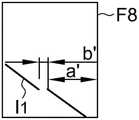
图8A是本发明再一实施例的清洁机器人的运作示意图;以及FIG. 8A is a schematic diagram of the operation of a cleaning robot according to still another embodiment of the present invention; and
图8B是图8A的清洁机器人的图像传感器所获取的图像帧的示意图。FIG. 8B is a schematic diagram of an image frame acquired by an image sensor of the cleaning robot of FIG. 8A .
附图标记说明Description of reference numerals
100 清洁机器人100 Cleaning Robots
11 第一光源模块11 The first light source module
111 第一光源111 The first light source
112 第一绕射光学组件112 The first diffractive optical component
121 第二光源121 Second light source
122 第二绕射光学组件122 Second diffractive optical assembly
13 图像传感器13 Image sensor
14 处理器14 processors
15 存储15 Storage
F 图像帧F image frame
C1、C2 控制信号C1, C2 control signal
具体实施方式Detailed ways
本发明各实施例的清洁机器人是用于消除行进方向前方的检测死角,以避免清洁机器人在运作的过程中与其他障碍物发生碰撞。The cleaning robot according to the embodiments of the present invention is used to eliminate the detection dead angle in front of the traveling direction, so as to avoid the cleaning robot from colliding with other obstacles during the operation.
请同时参照图1A及图1B,图1A是本发明第一实施例的清洁机器人100的运作示意图;图1B是本发明第一实施例的清洁机器人100的方框图。1A and 1B at the same time, FIG. 1A is a schematic diagram of the operation of the
清洁机器人100包含第一光源模块11、第二光源模块12、图像传感器13、处理器14以及存储15;其中,第一光源模块11、第二光源模块12及图像传感器13电性连接于处理器14并受其控制,存储15亦电性连接于或内建于处理器14以受其存取。The cleaning
第一光源模块11包含第一光源111及第一绕射光学组件(DOE1)112。第一光源111例如为发出不可见光的激光二极管,并受控于处理器14(例如通过控制信号C1)而发光,可持续发光或闪烁发光。第一绕射光学组件112用于使所述第一光源111所发出的光通过时产生垂直的第一光区段LS1。例如,图1A显示第一光源模块11设置于较靠近清洁机器人100的右侧,用于朝向清洁机器人100的行进方向的左前方投射第一光区段LS1。The first
第二光源模块12包含第二光源121及第二绕射光学组件(DOE2)122。第二光源121例如为发出不可见光的激光二极管,并受控于处理器14(例如通过控制信号C2)而发光,可持续发光或闪烁发光。第二绕射光学组件122用于使所述第二光源121所发出的光通过时产生垂直的第二垂直线段LS2。例如,图1A显示第二光源模块12设置于清洁机器人100的左侧,用于朝向清洁机器人100的行进方向的右前方投射第二垂直线段LS2。The second
通过这样的配置,第一光区段LS1及第二光区段LS2在清洁机器人100前方预定距离Dc的位置彼此交错后,在前方的行进表面上投射具有夹角(其根据第一光源模块11及第二光源模块12之间距及光区段投射角度而定)的两个光区段。同时,当前方存在墙面(可为任何物体的表面)时,则会在所述墙面投射彼此平行的两个光区段,亦即LS1、LS2,如图1A所示。本发明中,第一光区段LS1及第二光区段LS2的宽度并无特定限制,其根据图像传感器13的灵敏度及可检测距离而定。With such a configuration, after the first light segment LS1 and the second light segment LS2 are staggered with each other at a predetermined distance Dc in front of the
据此,当清洁机器人100的正前方具有小型物体时,例如小于第一光源模块11与第二光源模块12之间的距离的椅脚或桌脚等,所述小型物体会在所述交错处受到光源模块11、12照明而被图像传感器13检测,故可消除前方的检测死角。Accordingly, when there are small objects directly in front of the
图像传感器13例如为CCD图像传感器、CMOS图像传感器或其他用以检测光信号并输出电信号的光检测器。图像传感器13朝向清洁机器人100的行进方向以固定或可调的取样频率(优选同步于第一光源模块11和第二光源模块12的点亮)获取包含第一光区段LS1及第二光区段LS2的图像帧F并将其传送至处理器14进行后处理。更详言之,图像传感器13具有视角(FOV),其范围包含第一光区段LS1及第二光区段LS2。The
处理器14例如是微控制器(MCU)、中央处理器(CPU)、图形处理器(GPU)或特定功能集成电路(ASIC),其用于根据图像帧F中的第一光区段LS1相关的第一线段图像及第二光区段LS2相关的第二线段图像计算物体距离(举例说明于后)。The
存储15例如包含挥发性存储和/或非挥发性存储,用于预先储存计算物体距离和进行判断时所需的算法和参数。The
第一实施例中,处理器14控制第一光源模块11及第二光源模块12分时或同时投射第一光区段LS1及第二光区段LS2。In the first embodiment, the
请参照图2A-2B及图3A-3B所示,其显示处理器14控制第一光源模块11及第二光源模块12分时点亮的运作示意图,例如于第一时间点亮第一光源模块11(如图2A),接着于第二时间点亮第二光源模块12(如图3A),如此反复运作。Please refer to FIGS. 2A-2B and 3A-3B, which show schematic diagrams of the operation of the
如图2A所示,当第一光源模块11点亮且当前方物体W1位于最大检测距离D11时,图像传感器13则可获得包含第一光区段LS1相关的第一线段图像I11的图像帧F11;当前方物体W2位于最小检测距离D12时,图像传感器13则可获得包含第一光区段LS1相关的第一线段图像I12的图像帧F12。本实施例中,由于第一光源模块11朝向左前方投射第一光区段LS1,因此图像帧中I11及I12间的有效区间A1(effective area)可超过图像帧的尺寸的一半,亦即任何存在W1及W2之间的物体会出现在有效区间A1内。As shown in FIG. 2A , when the first
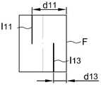
当清洁机器人100前方的不同距离具有不同物体时,例如下方的物体较近而上方的物体较远,图像传感器13则会获取如图2B所示的图像帧F,其中,第一线段图像的上半段I11(对应于第一光区段LS1的上半段)与图像帧F的右侧边缘距离d11而第一线段图像的下半段I13(对应于第一光区段LS1的下半段)与图像帧F的右侧边缘距离d13,其不同于d11。处理器14则计算第一线段图像(例如此时包含I11、I13)与图像帧F的第一边缘(此时为右侧边缘)的第一距离(例如此时为d11、d13),并根据所述第一距离d11、d13判断第一物体距离,其中每个第一距离d11、d13对应一个物体距离(例如d11对应所述上方物体与清洁机器人100的距离,而d13对应所述下方物体与清洁机器人100的距离)。When there are different objects at different distances in front of the
存储15预先纪录有第一距离与第一物体距离的第一相对关系,例如为数学式或对照表。当处理器14计算出一个或多个第一距离时,则存取存储15以求出相对各第一距离的物体距离。必须说明的是,虽然本实施例中的第一距离是以第一线段图像I11、I13与图像帧F的右侧边缘的距离为例进行说明,但其并非用以限定本发明。其他实施例中,第一距离也可选定为第一线段图像与图像帧F的左侧边缘的距离。The
如图3A所示,当第二光源模块12点亮且当前方物体W1位于最大检测距离D11时,图像传感器13则可获得包含第二光区段LS2相关的第二线段图像I11'的图像帧F11';当前方物体W2位于最小检测距离D12时,图像传感器13则可获得包含第二光区段LS2相关的第二线段图像I12'的图像帧F12'。本实施例中,由于第二光源模块12朝向右前方投射第二光区段LS2,因此图像帧中I11'及I12'间的有效区间A2亦可超过图像帧的尺寸的一半,亦即存在W1及W2之间的物体会出现在A2内。As shown in FIG. 3A , when the second
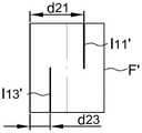
当清洁机器人100前方的不同距离具有不同物体时,例如下方的物体较近而上方的物体较远,图像传感器13则会获取如图3B所示的图像帧F',其中,第二线段图像的上半段I11'(对应于第二光区段LS2的上半段)与图像帧F'的左侧边缘距离d21而第二线段图像的下半段I13'(对应于第二光区段LS2的下半段)与图像帧F'的左侧边缘距离d23,其不同于d21。处理器14则计算第二线段图像(例如此时包含I11'、I13')与图像帧F'的第二边缘(此时为左侧边缘)的第二距离(例如d21、d23),并根据所述第二距离d21、d23判断第二物体距离,其中每个第二距离d21、d23对应一个物体距离(例如d21对应所述上方物体与清洁机器人100的距离,而d23对应所述下方物体与清洁机器人100的距离)。When there are different objects at different distances in front of the
存储15预先纪录有第二距离与第二物体距离的第二相对关系,例如为数学式或对照表。当处理器14计算出一个或多个第二距离时,则存取存储15以求出相对各第二距离的物体距离。必须说明的是,虽然本实施例中的第二距离是以第二线段图像I11'、I13'与图像帧F'的左侧边缘的距离为例进行说明,但其并非用以限定本发明。其他实施例中,第二距离也可选定为第二线段图像与图像帧F'的右侧边缘的距离。The
本实施例中,处理器14可先计算图像帧中的第一光区段LS1及第二光区段LS2对应的每个线段图像的平均线或重心线(多段线段图像时则计算多段平均线或多段重心线),并根据求得的平均线或求得的重心线与图像帧的两相对边缘的距离分别计算物体距离,如图2B及图3B所示I11、I13、I11'、I13'为相关的线段图像的平均线或所述重心线。但是如果线段图像够窄,则无需计算平均线或重心线。In this embodiment, the
可以了解的是,图2A及图3A显示的远近两个墙面W1及W2是指不同时间的独立检测状况,并非指第一光源模块11及第二光源模块12所发出的光穿过较近墙面W2。It can be understood that, the far and near two walls W1 and W2 shown in FIG. 2A and FIG. 3A refer to independent detection conditions at different times, and do not mean that the light emitted by the first
必须说明的是,图2A-2B及图3A-3B仅显示图像帧中投射于清洁机器人100前方墙面W1、W2上的光区段的图像,并未显示投射于清洁机器人100前方地面上的光区段的图像(将举例说明于后)。It must be noted that FIGS. 2A-2B and FIGS. 3A-3B only show the images of the light segments projected on the walls W1 and W2 in front of the
当处理器14控制第一光源模块11及第二光源模块12同时点亮时,第一光区段LS1及第二光区段LS2优选具有不同的区段特征,以供处理器14能够区别并分别计算物体距离。When the
例如参照图4所示,其为本发明第二实施例的清洁机器人400的运作示意图。第二实施例与第一实施例的差异在于,第一光源模块41是投射两条第一光区段LS1'以供处理器14能够与第二光区段LS2区隔。本实施例中,第一绕射光学组件112是配置成当第一光源111所发出的光经过时,产生多条垂直的第一光区段,其彼此互相平行。此外,与第一实施例相同的组件则以相同符号表示,并不再赘述。第二实施例中,处理器14计算第一光区段LS1'相关的物体距离的方式在于,先计算图像传感器13获取的图像帧F中的两条第一光区段LS1'的两条线段图像的平均线或重心线,并根据所述平均线或所述重心线与图像帧F的左右边缘其中之一的距离计算物体距离,其计算方式类似于图2B及图3B,本领域技术人员在了解图2B及图3B的说明后即能够了解,故于此不再赘述。For example, referring to FIG. 4 , which is a schematic diagram of the operation of the
例如参照图5所示,其为本发明第三实施例的清洁机器人500的运作示意图。第三实施例与第一实施例的差异在于,第一光源模块51是投射较宽或较亮的第一光区段LS1”以供处理器14能够与第二光区段LS2区隔。此外,与第一实施例相同的组件则以相同符号表示,并不再赘述。第三实施例中,处理器14计算第一光区段LS1”相关的物体距离的方式在于,先计算图像传感器13获取的图像帧F中的较宽或较亮的第一光区段LS1”的线段图像的平均线或重心线,并根据所述平均线或所述重心线与图像帧F的左右边缘其中之一的距离计算物体距离,其计算方式类似于图2B及图3B,本领域技术人员在了解图2B及图3B的说明后即能够了解,故于此不再赘述。For example, referring to FIG. 5 , which is a schematic diagram of the operation of the
换句话说,本发明中所述区段特征例如包含线段数目、线段宽度、线段亮度和/或线段的闪烁频率等。In other words, the segment features in the present invention include, for example, the number of line segments, the width of the line segment, the brightness of the line segment, and/or the flickering frequency of the line segment, and the like.
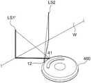
请参照图6A所示,其为本发明第四实施例的清洁机器人600的运作示意图。除了包含第一光源模块11、第二光源模块12、图像传感器13、处理器14及存储15(例如参照图1B)之外,清洁机器人600还包含第三光源模块63用于朝向行进方向投射水平光区段LS3。第四实施例中,与第一实施例相同的组件以相同符号表示。Please refer to FIG. 6A , which is a schematic diagram of the operation of the
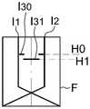
第四实施例中,第一光源模块11同样用于朝向行进方向投射垂直的第一光区段LS1;第二光源模块12同样用于朝向行进方向投射垂直的第二光区段LS2,因其已说明于前,故于此不再赘述。图像传感器13用于获取包含第一光区段LS1、第二光区段LS2及水平光区段LS3的图像帧F,例如图6B显示图像帧F包含对应第一光区段LS1的第一线段图像I1、对应第二光区段LS2的第二线段图像I2以及对应水平光区段LS3的第三线段图像I3。图6B中同时显示了第一线段图像I1及第二线段图像I2中,投射至地面(例如倾斜部分)及墙面(例如垂直部分)的线段图像;其中,倾斜部分与垂直部分的长度比例是根据前方物体的距离而定。In the fourth embodiment, the first
处理器14用于根据图像帧F中的第一光区段LS1相关的第一线段图像I1及第二光区段LS2相关的第二线段图像I2判断行进方向前方的悬崖(例如阶梯),并根据水平光区段LS3相关的第三线段图像I3计算前方的物体距离。The
例如参照图6C,当图像帧F中的第一线段图像I1与第二线段图像I2缺少部分下方线段图像时,表示前方不存在可行进表面。此时,处理器14则判断行进方向的前方存在悬崖而无法继续前进。因此,处理器14还可根据下方线段图像的长度计算与悬崖的距离,并在距离悬崖预定距离时控制清洁机器人600转向。本实施例中,存储15中预先纪录有倾斜线段图像的长度(例如从图像帧F下方边缘开始计算)与悬崖距离的相对关系(可为算法或对照表)。当处理器14计算出倾斜线段图像的长度后,则存取存储15以得到与悬崖的相对距离。For example, referring to FIG. 6C , when the first line segment image I1 and the second line segment image I2 in the image frame F lack part of the lower line segment image, it means that there is no traversable surface ahead. At this time, the
例如参照图6D,当图像帧F中的第三线段图像I3的全部或部分高度改变时,表示图像传感器13的视野前方存在物体。例如,图6D显示图像传感器13检测到小型物体(例如桌脚或椅脚),而使得第三线段图像I3的中央部分的高度自H0变化为H1。本实施例中,存储15中预先纪录有第三线段图像I3的不同高度与物体距离的相对关系(可为算法或对照表)。当处理器14计算出水平线段图像的高度(一个或多个)后,则存取存储15以得到相对应的物体距离。For example, referring to FIG. 6D , when all or part of the height of the third line segment image I3 in the image frame F changes, it indicates that there is an object in front of the field of view of the
图6D的实施例中,第三光源模块13例如是朝向上方投射水平光区段LS3,因此当物体越近,图像帧F中的第三线段图像I3的高度越低。反之,当第三光源模块13配置成朝向下方投射水平光区段LS3时,当物体越近时,图像帧F中的第三线段图像I3的高度越高。In the embodiment of FIG. 6D , the third
第四实施例中,处理器14是根据第三线段图像I3计算物体距离,但不根据第一线段图像I1及第二线段图像I2计算所述物体距离。此外,可选择将水平光区段LS3投射介于第一光区段LS1与第二光区段LS2之间,以达到消除清洁机器人600正前方的检测死角的问题。因此,既然可利用水平光区段LS3检测正前方的物体,所述第一光区段LS1与所述第二光区段LS2在清洁机器人600的前方可选择为彼此交错或彼此平行,并无特定限制。In the fourth embodiment, the
类似第一实施例至第三实施例,第四实施例中处理器14可控制第一光源模块11及第二光源模块12同时或分时投射第一光区段LS1及第二光区段LS2。当第一光源模块11及第二光源模块12同时投射第一光区段LS1及第二光区段LS2时,所述第一光区段LS1及所述第二光区段LS2优选具有不同的区段特征,例如具有不同宽度、亮度、数目和/或闪烁频率等,以利区隔。Similar to the first to third embodiments, in the fourth embodiment, the
第四实施例的另一种实施方式中,是使用光源组朝向行进方向投射第一光区段LS1、第二光区段LS2以及水平光区段LS3,其中,所述光源组包含第一光源模块11及第二光源模块12(例如参照图1B)。第一光源模块11包含第一光源111受控于处理器14而发光以及第一绕射光学组件112用于使所述第一光源111所发出的光通过时产生第一光区段LS1及水平光区段LS3。第二光源模块12包含第二光源121受控于处理器14而发光以及第二绕射光学组件122用于使所述第二光源121所发出的光通过时产生第二光区段LS2。更详言之,本实施方式中,光源组并不包含独立的光源模块用以产生水平光区段LS3,而是使第一绕射光学组件112配置成当光通过时能同时产生第一光区段LS1及水平光区段LS3。其他实施方中,光源组也可配置成是第二光源模块12同时投射第二光区段LS2及水平光区段LS3,而第一光源模块11仅投射第一光区段LS1。同理,水平光区段LS3优选投射介于第一光区段LS1与第二光区段LS2之间。In another implementation of the fourth embodiment, a light source group is used to project the first light segment LS1 , the second light segment LS2 and the horizontal light segment LS3 toward the traveling direction, wherein the light source group includes the first light source The
本实施方式中,图像传感器13同样用于获取视野包含第一光区段LS1、第二光区段LS2及水平光区段LS3的图像帧F,如图6B所示。处理器14同样用于获根据所述图像帧F中的第一光区段LS1相关的第一线段图像I1及第二光区段LS2相关的第二线段图像I2判断行进方向前方的悬崖并计算悬崖距离(如图6C所示),并根据所述图像帧F中的水平光区段LS3相关的第三线段图像I3计算物体距离(如图6D所示),其细节已举例说明于上,故于此不再赘述。In this embodiment, the
本实施方式中,处理器14同样用于控制第一光源模块11及第二光源模块12同时或分时点亮。当第一光源模块11及第二光源模块12同时点亮时,所述第一光区段LS1及所述第二光区段LS2优选具有不同的区段特征。In this embodiment, the
本发明说明中,垂直光区段是指其长度方向与清洁机器人100、400、500及600行进的平面垂直的方向的光区段而水平光区段是指其长度方向与所述平面平行的光区段。In the description of the present invention, a vertical light segment refers to a light segment whose length direction is perpendicular to the plane on which the
必须说明的是,本发明并不限制应用于清洁机器人,还可应用于清洁机器人以外的其他机器人,只要该机器人需要计算其行进方向前方的物体或悬崖距离。所述机器包含光源组、图像传感器13以及处理器14。如前所述,光源组用于朝向行进方向投射第一光区段LS1及第二光区段LS2。该第一光区段LS1及第二光区段LS2是垂直的光区段并在所述机器人前方的预定距离彼此交错。图像传感器13用于获取包含所述第一光区段LS1及所述第二光区段LS2的图像帧F。处理器14用于根据所述图像帧F中的所述第一光区段LS1相关的第一线段图像及所述第二光区段LS2相关的第二线段图像计算距离。所述光源组、图像传感器13以及处理器14的运作细节已说明如上,故于此不再赘述。It must be noted that the present invention is not limited to be applied to cleaning robots, and can also be applied to other robots other than cleaning robots, as long as the robot needs to calculate the distance to objects or cliffs in front of its traveling direction. The machine includes a light source group, an
此外,通过投射垂直线段,本发明实施例的机器人还可侦测其他形状的障碍物,例如判断隧道及计算悬崖高度。In addition, by projecting a vertical line segment, the robot of the embodiment of the present invention can also detect obstacles of other shapes, such as judging a tunnel and calculating the height of a cliff.
例如参照图7A所示,图像传感器13的视野FOV包含第一墙面W3及第二墙面W4,其中第一墙面W3突出于第二墙面W4而形成隧道。可以了解的是,所述第一墙面W3及第二墙面W4并非限定为墙壁表面,亦可为其他家具及家电的表面。For example, as shown in FIG. 7A , the field of view FOV of the
为简化图标,图7A仅显示清洁机器人100的部份组件而省略了其他组件。图7B为图像传感器13所获取的图像帧F7的示意图。本实施例中,是以第一光源模块11朝向图像传感器13的左前方投射第一光区段LS1(例如参照图2A)为例进行说明。本领域技术人员在了解以下说明后,即能够了解以第二光源模块12朝向图像传感器13的右前方投射第二光区段LS2(例如参照图3A)的实施方式。To simplify the icons, FIG. 7A only shows some components of the
如图7B所示,图像帧F7包含两平行线段图像分别与图像帧F7的右侧边缘具有横向距离b'及d',其中b'<d'。如前所述,存储15预先纪录有不同横向距离与物体距离的相对关系的算法或对照表。当处理器14计算出一个或多个所述横向距离时,则存取存储15以求出相对各横向距离的物体距离(此时为墙面距离)。此外,图像帧F7包含两垂直距离a'及c'。本实施例中,存储15还预先纪录有不同物体距离下垂直距离与实际高度的相对关系,例如算法或对照表。当处理器14计算出垂直距离a'和/或c'相对的物体距离时,即可根据垂直距离a'和/或c'计算出实际高度a和/或c。处理器14可判断清洁机器人100是否能够进入第一墙面W3下方的空间(即隧道)中。As shown in FIG. 7B , the image frame F7 includes two parallel line segment images with lateral distances b' and d' respectively from the right edge of the image frame F7, where b'<d'. As mentioned above, the
亦即,当所述图像帧F7中的第一线段图像I1具有两平行线段图像(例如图7B的两垂直线段图像),且所述两平行线段图像的上方线段图像与第一边缘(例如图7B的右侧边缘)的第一距离(例如图7B的b')小于所述两平行线段图像的下方线段图像与所述第一边缘的第一距离(例如图7B的d')时;或者当所述图像帧F7中的第二线段图像(未绘示)具有两平行线段图像,且所述两平行线段图像的上方线段图像与第二边缘(例如图7B的左侧边缘)的第二距离小于所述两平行线段图像的下方线段图像与所述第二边缘的第二距离时,处理器14则判断所述行进方向前方的存在隧道。That is, when the first line segment imageI1 in the image frame F7 has two parallel line segment images (for example, the two vertical line segment images in FIG. 7B ), and the upper line segment image of the two parallel line segment images and the first edge ( For example, when the first distance (for example, b' in FIG. 7B ) of the right edge of FIG. 7B is smaller than the first distance between the lower line segment image of the two parallel line segment images and the first edge (for example, d' in FIG. 7B ) ; or when the second line segment image (not shown) in the image frame F7 has two parallel line segment images, and the upper line segment image of the two parallel line segment images and the second edge (for example, the left edge of FIG. 7B ) When the second distance is smaller than the second distance between the lower line segment image of the two parallel line segment images and the second edge, the
例如参照图8A所示,图像传感器13的视野FOV包含第一地板FL1及第二地板FL2,其中第一地板FL1高出于第二地板FL2垂直距离b而形成悬崖。可以了解的是,所述第一地板FL1及所述第二地板FL2是指清洁机器人100可行进的任何表面。图8B为图像传感器13所获取的图像帧F8的示意图。本实施例同样是以第一光源模块11朝向图像传感器13的左前方投射第一光区段LS1为例进行说明。本领域技术人员在了解下列说明后,即能够了解以第二光源模块12朝向图像传感器13的右前方投射第二光区段LS2的实施方式。图8A同样仅显示清洁机器人100的部份组件而省略了其他构件。For example, as shown in FIG. 8A , the field of view FOV of the
由于第一地板FL1与第二地板FL2具有高度差,图像帧F8中的第一线段图像I1形成两断线且其间具有横向距离b'。图8B所示,图像帧F8的下方断线的前端与图像帧F8的右侧边缘具有横向距离a'。如前所述,存储15预先纪录有不同横向距离与物体距离(此处为悬崖距离)的相对关系的算法或对照表。当处理器14计算出所述横向距离a'时,则存取存储15以求出相对所述横向距离a'的悬崖距离a。存储15中还记录有不同横向距离a'及b'与实际距离a及b的对应关系,例如算法或对照表。当处理器14计算出横向距离a'及b'后,即能够同时判断悬崖距离a以及悬崖高度b。Since the first floor FL1 and the second floor FL2 have a height difference, the first line segment imageI1 in the image frame F8 forms two broken lines with a lateral distance b' therebetween. As shown in FIG. 8B, the front end of the lower broken line of the image frame F8 has a lateral distance a' from the right edge of the image frame F8. As mentioned above, the
综上所述,使用图像传感器的已知清洁机器人的前方具有检测死角,而具有于操作时会与检测死角内的物体发生碰撞的问题。因此,本发明另提供一种清洁机器人(图1A-1B、图4-6A),其通过于清洁机器人前方投射彼此交错的垂直光区段或同时投射垂直光区段及水平光区段,以消除行进方向的检测死角,并可同时达到悬崖检测的功效。To sum up, the known cleaning robot using an image sensor has a detection blind spot in front of it, and has a problem of colliding with an object in the detection blind spot during operation. Therefore, the present invention further provides a cleaning robot (FIGS. 1A-1B, 4-6A), which projects vertical light sections staggered with each other or simultaneously projects vertical light sections and horizontal light sections in front of the cleaning robot to achieve Eliminate the detection dead angle in the direction of travel, and can achieve the effect of cliff detection at the same time.
虽然本发明已通过前述实例披露,但是其并非用以限定本发明,任何本发明所属技术领域中具有通常知识技术人员,在不脱离本发明的精神和范围内,当可作各种的更动与修改。因此本发明的保护范围当视后附的权利要求所界定的范围为准。Although the present invention has been disclosed through the foregoing examples, it is not intended to limit the present invention. Any person with ordinary knowledge in the technical field to which the present invention pertains can make various modifications without departing from the spirit and scope of the present invention. with modification. Therefore, the protection scope of the present invention should be regarded as the scope defined by the appended claims.
Claims (19)
Priority Applications (1)
| Application Number | Priority Date | Filing Date | Title |
|---|---|---|---|
| CN202210735566.3ACN115153347B (en) | 2019-01-28 | 2019-10-23 | Robot capable of eliminating detection dead angles |
Applications Claiming Priority (2)
| Application Number | Priority Date | Filing Date | Title |
|---|---|---|---|
| US16/258,675US11353884B2 (en) | 2019-01-28 | 2019-01-28 | Robot without detection dead zone |
| US16/258,675 | 2019-01-28 |
Related Child Applications (1)
| Application Number | Title | Priority Date | Filing Date |
|---|---|---|---|
| CN202210735566.3ADivisionCN115153347B (en) | 2019-01-28 | 2019-10-23 | Robot capable of eliminating detection dead angles |
Publications (2)
| Publication Number | Publication Date |
|---|---|
| CN111481117A CN111481117A (en) | 2020-08-04 |
| CN111481117Btrue CN111481117B (en) | 2022-07-19 |
Family
ID=71731215
Family Applications (2)
| Application Number | Title | Priority Date | Filing Date |
|---|---|---|---|
| CN202210735566.3AActiveCN115153347B (en) | 2019-01-28 | 2019-10-23 | Robot capable of eliminating detection dead angles |
| CN201911012140.XAActiveCN111481117B (en) | 2019-01-28 | 2019-10-23 | Eliminate robots that detect dead spots |
Family Applications Before (1)
| Application Number | Title | Priority Date | Filing Date |
|---|---|---|---|
| CN202210735566.3AActiveCN115153347B (en) | 2019-01-28 | 2019-10-23 | Robot capable of eliminating detection dead angles |
Country Status (2)
| Country | Link |
|---|---|
| US (4) | US11353884B2 (en) |
| CN (2) | CN115153347B (en) |
Families Citing this family (8)
| Publication number | Priority date | Publication date | Assignee | Title |
|---|---|---|---|---|
| US10627518B2 (en) | 2017-06-02 | 2020-04-21 | Pixart Imaging Inc | Tracking device with improved work surface adaptability |
| US11821985B2 (en) | 2017-06-02 | 2023-11-21 | Pixart Imaging Inc. | Mobile robot performing multiple detections using image frames of same optical sensor |
| US11752635B2 (en) | 2017-06-02 | 2023-09-12 | Pixart Imaging Inc. | Mobile robot performing multiple detections using image frames of same optical sensor |
| US11691264B2 (en)* | 2017-06-02 | 2023-07-04 | Pixart Imaging Inc. | Mobile robot performing multiple detections using image frames of same optical sensor |
| US11009882B2 (en)* | 2018-01-12 | 2021-05-18 | Pixart Imaging Inc. | Method, system for obstacle detection and a sensor subsystem |
| US12379499B2 (en) | 2021-07-16 | 2025-08-05 | Pixart Imaging Inc. | Distance measurement device using two algorithms |
| CN114454162B (en)* | 2022-01-10 | 2023-05-26 | 广东技术师范大学 | Mobile robot complex intersection anti-collision method and system |
| TWI849902B (en)* | 2022-05-16 | 2024-07-21 | 鈺立微電子股份有限公司 | Image capturing apparatus and automatic sweeping apparatus |
Citations (6)
| Publication number | Priority date | Publication date | Assignee | Title |
|---|---|---|---|---|
| EP2623010A2 (en)* | 2012-02-04 | 2013-08-07 | LG Electronics, Inc. | Robot cleaner |
| CN104586322A (en)* | 2013-10-31 | 2015-05-06 | Lg电子株式会社 | Moving robot and operating method |
| CN107024483A (en)* | 2015-10-13 | 2017-08-08 | 弗兰克公司 | The three-dimensional inspection of optical communications link |
| EP3349087A1 (en)* | 2017-01-16 | 2018-07-18 | LG Electronics Inc. | Moving robot |
| CN108603935A (en)* | 2016-03-15 | 2018-09-28 | 伊莱克斯公司 | The method that robotic cleaning device and robotic cleaning device carry out cliff detection |
| CN207979622U (en)* | 2016-05-17 | 2018-10-19 | Lg电子株式会社 | Robot cleaner |
Family Cites Families (23)
| Publication number | Priority date | Publication date | Assignee | Title |
|---|---|---|---|---|
| US8412377B2 (en)* | 2000-01-24 | 2013-04-02 | Irobot Corporation | Obstacle following sensor scheme for a mobile robot |
| TWI245902B (en)* | 2004-05-14 | 2005-12-21 | Chung Shan Inst Of Science | Microstructure angular velocity sensor device |
| US9002511B1 (en)* | 2005-10-21 | 2015-04-07 | Irobot Corporation | Methods and systems for obstacle detection using structured light |
| US8629988B2 (en)* | 2009-04-20 | 2014-01-14 | Javad Gnss, Inc. | Laser beam image contrast enhancement |
| US9020641B2 (en)* | 2012-06-07 | 2015-04-28 | Samsung Electronics Co., Ltd. | Obstacle sensing module and cleaning robot including the same |
| ES2610755T3 (en)* | 2012-08-27 | 2017-05-03 | Aktiebolaget Electrolux | Robot positioning system |
| KR102152641B1 (en)* | 2013-10-31 | 2020-09-08 | 엘지전자 주식회사 | Mobile robot |
| CN103941307B (en)* | 2014-01-13 | 2018-02-16 | 苏州爱普电器有限公司 | A kind of clean robot and the method for controlling its avoiding obstacles |
| CN106415423B (en)* | 2014-07-10 | 2021-01-01 | 伊莱克斯公司 | Method for detecting a measurement error of a robotic cleaning device |
| US9840003B2 (en)* | 2015-06-24 | 2017-12-12 | Brain Corporation | Apparatus and methods for safe navigation of robotic devices |
| US9919425B2 (en)* | 2015-07-01 | 2018-03-20 | Irobot Corporation | Robot navigational sensor system |
| CN105286729B (en)* | 2015-09-25 | 2018-09-11 | 江苏美的清洁电器股份有限公司 | Sweeping robot |
| US10136120B2 (en)* | 2016-04-15 | 2018-11-20 | Microsoft Technology Licensing, Llc | Depth sensing using structured illumination |
| TWI653964B (en)* | 2016-05-17 | 2019-03-21 | Lg電子股份有限公司 | Mobile robot and its control method |
| TWI639021B (en)* | 2016-05-17 | 2018-10-21 | 南韓商Lg電子股份有限公司 | Mobile robot and method of controlling the same |
| KR102662949B1 (en)* | 2016-11-24 | 2024-05-02 | 엘지전자 주식회사 | Artificial intelligence Moving robot and control method thereof |
| KR102235270B1 (en)* | 2017-01-18 | 2021-04-01 | 엘지전자 주식회사 | Moving Robot and controlling method |
| DE102017208485A1 (en)* | 2017-05-19 | 2018-11-22 | Fraunhofer-Gesellschaft zur Förderung der angewandten Forschung e.V. | Arrangement and method for non-contact distance determination in the manner of the light-section method |
| EP3629869B1 (en)* | 2017-06-02 | 2023-08-16 | Aktiebolaget Electrolux | Method of detecting a difference in level of a surface in front of a robotic cleaning device |
| CN208286955U (en)* | 2017-08-22 | 2018-12-28 | 江苏美的清洁电器股份有限公司 | Clean robot |
| KR102428216B1 (en)* | 2017-12-04 | 2022-08-01 | 엘지전자 주식회사 | a Moving robot Using artificial intelligence, Controlling method for the moving robot, Controlling system for the moving robot |
| US11009882B2 (en)* | 2018-01-12 | 2021-05-18 | Pixart Imaging Inc. | Method, system for obstacle detection and a sensor subsystem |
| KR102048364B1 (en)* | 2018-04-13 | 2019-11-25 | 엘지전자 주식회사 | Robot cleaner |
- 2019
- 2019-01-28USUS16/258,675patent/US11353884B2/enactiveActive
- 2019-10-23CNCN202210735566.3Apatent/CN115153347B/enactiveActive
- 2019-10-23CNCN201911012140.XApatent/CN111481117B/enactiveActive
- 2022
- 2022-04-29USUS17/732,576patent/US11675365B2/enactiveActive
- 2023
- 2023-04-28USUS18/140,630patent/US11994871B2/enactiveActive
- 2024
- 2024-04-17USUS18/637,491patent/US12360537B2/enactiveActive
Patent Citations (6)
| Publication number | Priority date | Publication date | Assignee | Title |
|---|---|---|---|---|
| EP2623010A2 (en)* | 2012-02-04 | 2013-08-07 | LG Electronics, Inc. | Robot cleaner |
| CN104586322A (en)* | 2013-10-31 | 2015-05-06 | Lg电子株式会社 | Moving robot and operating method |
| CN107024483A (en)* | 2015-10-13 | 2017-08-08 | 弗兰克公司 | The three-dimensional inspection of optical communications link |
| CN108603935A (en)* | 2016-03-15 | 2018-09-28 | 伊莱克斯公司 | The method that robotic cleaning device and robotic cleaning device carry out cliff detection |
| CN207979622U (en)* | 2016-05-17 | 2018-10-19 | Lg电子株式会社 | Robot cleaner |
| EP3349087A1 (en)* | 2017-01-16 | 2018-07-18 | LG Electronics Inc. | Moving robot |
Also Published As
| Publication number | Publication date |
|---|---|
| US20240264596A1 (en) | 2024-08-08 |
| US20220253068A1 (en) | 2022-08-11 |
| CN111481117A (en) | 2020-08-04 |
| US20230259139A1 (en) | 2023-08-17 |
| US11353884B2 (en) | 2022-06-07 |
| US11675365B2 (en) | 2023-06-13 |
| CN115153347A (en) | 2022-10-11 |
| US11994871B2 (en) | 2024-05-28 |
| CN115153347B (en) | 2023-12-26 |
| US12360537B2 (en) | 2025-07-15 |
| US20200241550A1 (en) | 2020-07-30 |
Similar Documents
| Publication | Publication Date | Title |
|---|---|---|
| CN111481117B (en) | Eliminate robots that detect dead spots | |
| CN111035321B (en) | Cleaning robot capable of detecting two-dimensional depth information and operation method thereof | |
| US10456004B2 (en) | Mobile robot | |
| US12140674B2 (en) | Electronic device with light sources emitting in different directions | |
| US10216331B2 (en) | Touch projection system and touch sensitivity adjusting method thereof | |
| US12285876B2 (en) | Cleaning robot capable of eliminating reflection interference | |
| CN110115548B (en) | Control device for automatic cleaner and control method for automatic cleaner | |
| CN114019533B (en) | Mobile Robots | |
| CN112099482A (en) | A mobile robot that can increase the accuracy of step distance judgment | |
| US20250222593A1 (en) | Cleaning robot capable of eliminating reflection interference |
Legal Events
| Date | Code | Title | Description |
|---|---|---|---|
| PB01 | Publication | ||
| PB01 | Publication | ||
| SE01 | Entry into force of request for substantive examination | ||
| SE01 | Entry into force of request for substantive examination | ||
| GR01 | Patent grant | ||
| GR01 | Patent grant |