CN111474871A - Power supply control device and method for home appliance control system - Google Patents
Power supply control device and method for home appliance control systemDownload PDFInfo
- Publication number
- CN111474871A CN111474871ACN201910064447.8ACN201910064447ACN111474871ACN 111474871 ACN111474871 ACN 111474871ACN 201910064447 ACN201910064447 ACN 201910064447ACN 111474871 ACN111474871 ACN 111474871A
- Authority
- CN
- China
- Prior art keywords
- power
- power supply
- control
- switch
- home appliance
- Prior art date
- Legal status (The legal status is an assumption and is not a legal conclusion. Google has not performed a legal analysis and makes no representation as to the accuracy of the status listed.)
- Granted
Links
Images


Classifications
- G—PHYSICS
- G05—CONTROLLING; REGULATING
- G05B—CONTROL OR REGULATING SYSTEMS IN GENERAL; FUNCTIONAL ELEMENTS OF SUCH SYSTEMS; MONITORING OR TESTING ARRANGEMENTS FOR SUCH SYSTEMS OR ELEMENTS
- G05B19/00—Programme-control systems
- G05B19/02—Programme-control systems electric
- G05B19/04—Programme control other than numerical control, i.e. in sequence controllers or logic controllers
- G05B19/042—Programme control other than numerical control, i.e. in sequence controllers or logic controllers using digital processors
- G05B19/0423—Input/output
- G—PHYSICS
- G05—CONTROLLING; REGULATING
- G05B—CONTROL OR REGULATING SYSTEMS IN GENERAL; FUNCTIONAL ELEMENTS OF SUCH SYSTEMS; MONITORING OR TESTING ARRANGEMENTS FOR SUCH SYSTEMS OR ELEMENTS
- G05B2219/00—Program-control systems
- G05B2219/20—Pc systems
- G05B2219/21—Pc I-O input output
- G05B2219/21119—Circuit for signal adaption, voltage level shift, filter noise
Landscapes
- Physics & Mathematics (AREA)
- General Physics & Mathematics (AREA)
- Engineering & Computer Science (AREA)
- Automation & Control Theory (AREA)
- Remote Monitoring And Control Of Power-Distribution Networks (AREA)
Abstract
Translated fromChinese
Description
Translated fromChinese技术领域technical field
本发明涉及家电设备控制技术领域,具体涉及一种家电控制系统的供电控制装置及方法。The invention relates to the technical field of home appliance control, in particular to a power supply control device and method for a home appliance control system.
背景技术Background technique
随着智能家电技术的发展,家电设备的家电控制系统越来越复杂,家电控制系统中的电子模块数量也越来越多,通常每个电子模块都有各自的控制芯片,电控系统的主机通过总线通讯的方式与各个电子模块数据通讯。一般地,当电控系统的主机进入关机状态或睡眠模式后,各个电子模块也需要进入关机状态或睡眠模式,以降低家电的功耗,然而通常电子模块进入关机状态或睡眠模式后,因为电子模块的电源并没有切断,电子模块中的一些电子线路仍在持续耗电,从而使家电设备的整体功耗仍然较高。With the development of smart home appliance technology, the home appliance control system of home appliance equipment is becoming more and more complex, and the number of electronic modules in the home appliance control system is also increasing. Usually, each electronic module has its own control chip, and the host of the electronic control system It communicates data with each electronic module by means of bus communication. Generally, when the host of the electronic control system enters the shutdown state or sleep mode, each electronic module also needs to enter the shutdown state or sleep mode to reduce the power consumption of the home appliance. The power supply of the module is not cut off, and some electronic circuits in the electronic module continue to consume power, so that the overall power consumption of the home appliance is still high.
相应地,本领域需要一种电源控制方法来解决上述问题。Accordingly, there is a need in the art for a power control method to solve the above problems.
发明内容SUMMARY OF THE INVENTION
为了解决现有技术中的上述问题,即为了解决如何降低家电设备功耗的技术问题,本发明的一方面,提供了一种家电控制系统的供电控制装置,所述供电控制装置应用于基于总线结构的家电控制系统,所述家电控制系统包括通过总线通信连接的主机和从机,所述供电控制装置包括电源控制模块,所述电源控制模块包括电源开关电路和开关控制电路;In order to solve the above problems in the prior art, that is, in order to solve the technical problem of how to reduce the power consumption of home appliances, an aspect of the present invention provides a power supply control device for a home appliance control system, which is applied to a bus-based power supply control device. A home appliance control system with a structure, the home appliance control system includes a master and a slave connected by bus communication, the power supply control device includes a power control module, and the power control module includes a power switch circuit and a switch control circuit;
所述电源开关电路设置于所述从机的高电平电源线上,用于导通或切断所述高电平电源线,以便所述家电控制系统的电源能够通过所述高电平电源线向所述从机供电或者切断所述电源;The power switch circuit is arranged on the high-level power line of the slave, and is used to turn on or off the high-level power line, so that the power of the home appliance control system can pass through the high-level power line supplying power to the slave or cutting off the power;
所述开关控制电路用于根据接收的控制指令控制所述电源开关电路开通或关断,以便导通或切断所述高电平电源线。The switch control circuit is used to control the power switch circuit to be turned on or off according to the received control instruction, so as to turn on or off the high-level power line.
进一步地,本发明提供的一个优选实施方案为:Further, a preferred embodiment provided by the present invention is:
所述电源开关电路包括PNP型三极管,所述PNP型三极管的集电极与所述高电平电源线的电源输入侧连接,所述PNP型三极管的发射极与所述高电平电源线的电源输出侧连接,所述PNP型三极管的基极与所述开关控制电路连接。The power switch circuit includes a PNP transistor, the collector of the PNP transistor is connected to the power input side of the high-level power line, and the emitter of the PNP transistor is connected to the power supply of the high-level power line. The output side is connected, and the base of the PNP triode is connected to the switch control circuit.
进一步地,本发明提供的一个优选实施方案为:Further, a preferred embodiment provided by the present invention is:
所述开关控制电路包括NPN型三极管和开关指令接收电路;The switch control circuit includes an NPN transistor and a switch command receiving circuit;
所述NPN型三极管的集电极与所述PNP型三极管的基极连接,所述NPN型三极管的发射极与所述从机的低电平电源线连接,所述NPN型三极管的基极与所述开关指令接收电路连接;The collector of the NPN triode is connected to the base of the PNP triode, the emitter of the NPN triode is connected to the low-level power line of the slave, and the base of the NPN triode is connected to the slave. The switch command receiving circuit is connected;
所述开关指令接收电路分别与所述从机的总线或控制器连接,用于接收所述主机通过所述总线发送的控制指令或者所述控制器发送的控制指令。The switch instruction receiving circuit is respectively connected with the bus or the controller of the slave, and is used for receiving the control instruction sent by the host through the bus or the control instruction sent by the controller.
进一步地,本发明提供的一个优选实施方案为:Further, a preferred embodiment provided by the present invention is:
所述开关指令接收电路包括第一二极管和第二二极管;The switch command receiving circuit includes a first diode and a second diode;
所述第一二极管的阳极与所述总线连接,所述第一二极管的阴极与所述NPN型三极管的基极连接;The anode of the first diode is connected to the bus, and the cathode of the first diode is connected to the base of the NPN triode;
所述第二二极管的阳极与所述控制器连接,所述第二二极管的阴极与所述NPN型三极管的基极连接。The anode of the second diode is connected to the controller, and the cathode of the second diode is connected to the base of the NPN triode.
进一步地,本发明提供的一个优选实施方案为:Further, a preferred embodiment provided by the present invention is:
所述从机的数量是多个,所述电源控制模块的数量也是多个并且每个所述电源控制模块分别设置在一个所述从机上。The number of the slaves is multiple, the number of the power control modules is also multiple, and each of the power control modules is respectively arranged on one of the slaves.
本发明的另一方面,还提供了一种家电控制系统的供电控制装置的供电控制方法,所述供电控制方法包括:Another aspect of the present invention further provides a power supply control method of a power supply control device of a home appliance control system, the power supply control method comprising:
所述家电控制系统的主机上电后判断是否向所述家电控制系统的从机供电;After the host of the home appliance control system is powered on, determine whether to supply power to the slaves of the home appliance control system;
若向所述从机供电,则通过所述总线向所述从机中电源控制模块的开关控制电路发送开通控制指令,以使所述开关控制电路根据所述开通控制指令控制所述电源控制模块的电源开关电路开通;If power is supplied to the slave, a turn-on control instruction is sent to the switch control circuit of the power control module in the slave through the bus, so that the switch control circuit controls the power control module according to the turn-on control instruction The power switch circuit is turned on;
所述从机的控制器上电后向所述开关控制电路发送维持开通控制指令,以使所述开关控制电路根据所述维持开通控制指令控制所述电源开关电路维持开通状态。After the controller of the slave is powered on, it sends a hold-on control instruction to the switch control circuit, so that the switch control circuit controls the power switch circuit to maintain an on state according to the hold-on control instruction.
进一步地,本发明提供的一个优选实施方案为:Further, a preferred embodiment provided by the present invention is:
在“所述从机的控制器上电后向所述开关控制电路发送维持开通控制指令”的步骤之后,所述方法还包括:After the step of "sending the switch control circuit to maintain a turn-on control command after the controller of the slave is powered on", the method further includes:
所述主机判断是否停止向所述从机供电;The host determines whether to stop supplying power to the slave;
若停止向所述从机供电,则向所述控制器发送停止供电指令;If the power supply to the slave is stopped, sending a stop power supply instruction to the controller;
并且在所述控制器根据所述停止供电指令控制所述电源开关电路停止维持所述开通状态后,通过所述总线向所述开关控制电路发送关断控制指令,以使所述开关控制电路根据所述关断控制指令控制所述电源开关电路关断。And after the controller controls the power switch circuit to stop maintaining the on state according to the power supply stop instruction, sends a shutdown control instruction to the switch control circuit through the bus, so that the switch control circuit The shutdown control instruction controls the power switch circuit to be turned off.
进一步地,本发明提供的一个优选实施方案为:Further, a preferred embodiment provided by the present invention is:
所述维持开通控制指令是高电平信号,“所述控制器根据所述停止供电指令控制所述电源开关电路停止维持所述开通状态”的步骤具体包括:The maintaining turn-on control command is a high-level signal, and the step of “the controller controls the power switch circuit to stop maintaining the turn-on state according to the power supply stop command” specifically includes:
所述控制器根据所述停止供电指令向所述开关控制电路发送低电平信号。The controller sends a low-level signal to the switch control circuit according to the power supply stop instruction.
进一步地,本发明提供的一个优选实施方案为:Further, a preferred embodiment provided by the present invention is:
“所述家电控制系统的主机上电后判断是否向所述家电控制系统的从机供电”的步骤进一步包括:The step of "judging whether to supply power to the slaves of the home appliance control system after the host of the home appliance control system is powered on" further includes:
若不向所述从机供电,则通过所述总线向所述开关控制电路发送关断控制指令,以使所述开关控制电路根据所述关断控制指令控制所述电源开关电路关断。If no power is supplied to the slave, a shutdown control command is sent to the switch control circuit through the bus, so that the switch control circuit controls the power switch circuit to be turned off according to the shutdown control command.
进一步地,本发明提供的一个优选实施方案为:Further, a preferred embodiment provided by the present invention is:
所述开通控制指令是高电平信号,所述关断控制指令是低电平信号。The turn-on control command is a high-level signal, and the turn-off control command is a low-level signal.
与最接近的现有技术相比,上述技术方法至少具有如下有益效果:Compared with the closest prior art, the above-mentioned technical method at least has the following beneficial effects:
本发明提供的家电控制系统的供电控制装置应用于基于总线结构的家电控制系统,其中,家电控制系统包括通过总线通信连接的主机和从机。具体地,供电控制装置主要包括电源控制模块,电源控制模块包括电源开关电路和开关控制电路,电源开关电路设置于从机的高电平电源线上,用于导通或切断高电平电源线,以便家电控制系统中的电源能够通过高电平电源线向从机供电或切断电源向从机供电;开关控制电路用于根据接收的控制指令控制电源开关电路开通或关断,以便导通或切断高电平电源线。上述供电控制装置结构简单,成本较低,并且能够有效降低家电控制系统的能耗。The power supply control device of the home appliance control system provided by the present invention is applied to a home appliance control system based on a bus structure, wherein the home appliance control system includes a host computer and a slave computer connected through bus communication. Specifically, the power supply control device mainly includes a power control module. The power control module includes a power switch circuit and a switch control circuit. The power switch circuit is arranged on the high-level power line of the slave and is used to turn on or cut off the high-level power line. , so that the power supply in the home appliance control system can supply power to the slave machine or cut off the power supply to the slave machine through the high-level power line; the switch control circuit is used to control the power switch circuit to be turned on or off according to the received control command, so as to turn on or off. Disconnect the high-level power cord. The above-mentioned power supply control device has a simple structure and low cost, and can effectively reduce the energy consumption of the home appliance control system.
进一步地,本发明提供的家电控制系统的供电控制装置的供电控制方法至少包括如下步骤:家电控制系统的主机上电后判断是否向家电控制系统的从机供电,若向从机供电,则通过总线向从机中电源控制模块的开关控制电路发送开通控制指令,以使开关控制电路根据开通控制指令控制电源控制模块的电源开关电路开通;从机的控制器上电后向开关控制电路发送维持开通控制指令,以使开关控制电路根据维持开通控制指令控制电源开关电路维持在开通状态。基于上述步骤可以有效控制从机的开通状态,实现主机向从机的供电控制。Further, the power supply control method of the power supply control device of the home appliance control system provided by the present invention at least includes the following steps: after the host of the home appliance control system is powered on, it is judged whether to supply power to the slave of the home appliance control system, and if the power is supplied to the slave, pass the power to the slave. The bus sends a turn-on control command to the switch control circuit of the power control module in the slave, so that the switch control circuit controls the power switch circuit of the power control module to turn on according to the turn-on control command; after the controller of the slave is powered on, it sends a maintenance command to the switch control circuit. The turn-on control command enables the switch control circuit to control the power switch circuit to maintain the turn-on state according to the sustain turn-on control command. Based on the above steps, the open state of the slave can be effectively controlled, and the power supply control of the master to the slave can be realized.
进一步地,在停止向从机供电时,切断从机与电源的连接,使从机彻底断电,同时也不影响主机的工作,有效降低家电控制系统的能耗。Further, when the power supply to the slave is stopped, the connection between the slave and the power supply is cut off, so that the slave is completely powered off, and at the same time, the work of the host is not affected, and the energy consumption of the home appliance control system is effectively reduced.
附图说明Description of drawings
图1为本发明实施例中一种家电控制系统的供电控制装置的主要结构示意图;1 is a schematic diagram of the main structure of a power supply control device of a home appliance control system in an embodiment of the present invention;
图2为本发明实施例中一种电源控制模块的主要结构示意图;FIG. 2 is a schematic diagram of the main structure of a power supply control module in an embodiment of the present invention;
图3为本发明实施例中一种主机的自主控制电路的主要结构示意图;3 is a schematic diagram of the main structure of an autonomous control circuit of a host in an embodiment of the present invention;
图4为本发明实施例中一种主机的主要结构示意图;4 is a schematic diagram of the main structure of a host in an embodiment of the present invention;
图5为本发明实施例中一种从机的主要结构示意图;5 is a schematic diagram of the main structure of a slave in an embodiment of the present invention;
图6为本发明实施例中一种家电控制系统的供电控制装置的供电控制方法的主要步骤示意图。6 is a schematic diagram of main steps of a power supply control method of a power supply control device of a home appliance control system according to an embodiment of the present invention.
具体实施方式Detailed ways
下面参照附图来描述本发明的优选实施方式。本领域技术人员应当理解的是,这些实施方式仅仅用于解释本发明的技术原理,并非旨在限制本发明的保护范围。Preferred embodiments of the present invention are described below with reference to the accompanying drawings. It should be understood by those skilled in the art that these embodiments are only used to explain the technical principle of the present invention, and are not intended to limit the protection scope of the present invention.
下面结合附图,对本发明提供的一种家电控制系统的供电控制装置进行说明。The following describes a power supply control device of a home appliance control system provided by the present invention with reference to the accompanying drawings.
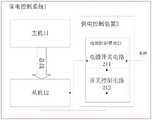
参阅附图1,图1示例性示出了本实施例中家电控制系统的供电控制装置的主要结构。如图1所示,本实施例中家电控制系统的供电控制装置2应用于基于总线结构的家电控制系统1,该家电控制系统1主要包括通过总线通信连接的主机11和从机12。具体地,本实施例中供电控制装置2可以包括电源控制模块21,该电源控制模块21可以包括电源开关电路211和开关控制电路212。电源开关电路211设置于从机12的高电平电源线上,可以用于导通或切断高电平电源线,以便家电控制系统的电源能够通过高电平电源线向从机12供电或切断电源。开关控制电路212可以用于根据接收的控制指令控制电源开关电路211开通或关断,以便导通或切断高电平电源线。Referring to FIG. 1 , FIG. 1 exemplarily shows the main structure of the power supply control device of the home appliance control system in this embodiment. As shown in FIG. 1 , the power
继续参阅附图2,图2示例性示出了图1所示供电控制装置中电源控制模块21的主要结构,如图2所示,本实施例中电源开关电路主要包括PNP型三极管Q1、偏置电阻R28和限流电阻R3。PNP型三极管Q1的集电极与高电平电源线的电源输入侧连接,PNP型三极管Q1的发射极与高电平电源线的电源输出侧(图2所示的+12V-CTL)连接,PNP型三极管Q1的基极通过限流电阻R3与开关控制电路212连接,PNP型三极管Q1的基极还通过偏置电阻R28与PNP型三极管Q1的发射极连接。开关控制电路212主要包括NPN型三极管Q4、偏置电阻(图2所示阻值为10K的电阻)、限流电阻(图2所示阻值为4K7的电阻)和开关指令接收电路。NPN型三极管Q4的集电极与PNP型三极管Q1的基极连接。NPN型三极管Q4的发射极与从机的低电平电源线GND连接。NPN型三极管Q4的基极与开关指令接收电路连接。开关指令接收电路分别与从机的总线或控制器连接,该开关指令接收电路可以用于接收主机通过总线发送的控制指令或者控制器发送的控制指令。Continuing to refer to FIG. 2, FIG. 2 exemplarily shows the main structure of the power supply control module 21 in the power supply control device shown in FIG. 1. As shown in FIG. 2, the power switch circuit in this embodiment mainly includes a PNP transistor Q1, a bias Set resistor R28 and current limiting resistor R3. The collector of the PNP transistor Q1 is connected to the power input side of the high-level power line, and the emitter of the PNP-type transistor Q1 is connected to the power output side of the high-level power line (+12V-CTL shown in Figure 2), PNP The base of the PNP transistor Q1 is connected to the switch control circuit 212 through a current limiting resistor R3, and the base of the PNP transistor Q1 is also connected to the emitter of the PNP transistor Q1 through a bias resistor R28. The switch control circuit 212 mainly includes an NPN transistor Q4, a bias resistor (the resistor with a resistance value of 10K shown in FIG. 2 ), a current limiting resistor (the resistor with a resistance value of 4K7 shown in FIG. 2 ) and a switch command receiving circuit. The collector of the NPN transistor Q4 is connected to the base of the PNP transistor Q1. The emitter of the NPN transistor Q4 is connected to the low-level power line GND of the slave. The base of the NPN transistor Q4 is connected to the switch command receiving circuit. The switch command receiving circuit is respectively connected with the bus or the controller of the slave, and the switch command receiving circuit can be used for receiving the control command sent by the host through the bus or the control command sent by the controller.
如图2所示,本实施例中开关指令接收电路主要包括第一二极管和第二二极管。第一二极管的阳极与总线连接,第一二极管的阴极与NPN型三极管Q4的基极连接。第二二极管的阳极与控制器连接,第二二极管的阴极与NPN型三极管的基极连接。As shown in FIG. 2 , the switch command receiving circuit in this embodiment mainly includes a first diode and a second diode. The anode of the first diode is connected to the bus, and the cathode of the first diode is connected to the base of the NPN transistor Q4. The anode of the second diode is connected to the controller, and the cathode of the second diode is connected to the base of the NPN triode.
在本实施例的一个可选实施方案中,当家电控制系统包括多个从机时,供电控制装置2可以包括多个电源控制模块21,并且每个电源控制模块21分别设置在一个从机上。如图3所示,本实施方案中家电控制系统包括分别与主机连接的从机1至n,供电控制装置2可以包括n个电源控制模块21(图4未示出),n个电源控制模块21分别与n个从机一一相连。In an optional implementation of this embodiment, when the home appliance control system includes multiple slaves, the power
继续参阅附图4和5,图4和5分别示例性示出了本实施方案中主机和从机的主要结构。Continue to refer to Figures 4 and 5, Figures 4 and 5 respectively illustrate the main structures of the master and the slave in this embodiment.
如图4所示,本实施中主机包括NPN型三极管Q3、PNP型三极管Q6、PNP型三极管Q10和NPN型三极管Q7。NPN型三极管Q3的集电极分别与限流电阻R2的一端和端口BUS_RXD连接,限流电阻R2的另一端与+5V高电平电压连接,端口BUS_RXD为主机的接收端口,NPN型三极管Q3的发射极与主机的低电平电源线GND连接,NPN型三极管Q3的基极与PNP型三极管Q6的集电极连接。其中,NPN型三极管Q3还包括限流电阻(图4中NPN型三极管Q3内阻值为4K7的电阻)、偏置电阻(图4中NPN型三极管Q3内阻值为10K的电阻)。PNP型三极管Q6的发射极连接+12V高电平电源,PNP型三极管Q6的基极分别与电容C1,偏置电阻R5和限流电阻R9的一端连接,电容C1和偏置电阻R5的另一端连接+12V高电平电源,限流电阻R9的另一端连接NPN型三极管Q7的集电极。NPN型三极管Q7的发射极连接主机的低电平电源线GND,NPN型三极管Q7的基极连接PNP型三极管Q10的集电极连接。PNP型三极管Q10的基极连接限流电阻R15的一端,限流电阻的另一端连接端口BUS_TXD,端口BUS_TXD为主机的发送端口。PNP型三极管Q10的发射极连接+5V高电平电源。在PNP型三极管Q10的发射极和基极之间连接有偏置电阻。在NPN型三极管Q7的发射极还连接限流电阻R10,限流电阻R10的另一端连接总线BUS,在总线BUS和+12V电源之间还连接上拉电阻R6。主机通过总线BUS与从机通信连接。As shown in FIG. 4 , in this embodiment, the host includes an NPN type triode Q3 , a PNP type triode Q6 , a PNP type triode Q10 and an NPN type triode Q7 . The collector of the NPN transistor Q3 is connected to one end of the current limiting resistor R2 and the port BUS_RXD respectively, the other end of the current limiting resistor R2 is connected to the +5V high level voltage, the port BUS_RXD is the receiving port of the host, and the transmitting port of the NPN transistor Q3 The pole is connected to the low-level power line GND of the host, and the base of the NPN transistor Q3 is connected to the collector of the PNP transistor Q6. Among them, the NPN transistor Q3 also includes a current-limiting resistor (the internal resistance of the NPN transistor Q3 in Figure 4 is 4K7) and a bias resistor (the NPN transistor Q3 in Figure 4 has an internal resistance of 10K resistance). The emitter of the PNP transistor Q6 is connected to the +12V high-level power supply, the base of the PNP transistor Q6 is respectively connected to one end of the capacitor C1, the bias resistor R5 and the current limiting resistor R9, and the other end of the capacitor C1 and the bias resistor R5 Connect the +12V high-level power supply, and the other end of the current limiting resistor R9 is connected to the collector of the NPN transistor Q7. The emitter of the NPN transistor Q7 is connected to the low-level power line GND of the host, and the base of the NPN transistor Q7 is connected to the collector of the PNP transistor Q10. The base of the PNP transistor Q10 is connected to one end of the current limiting resistor R15, and the other end of the current limiting resistor is connected to the port BUS_TXD, and the port BUS_TXD is the sending port of the host. The emitter of the PNP transistor Q10 is connected to the +5V high-level power supply. A bias resistor is connected between the emitter and the base of the PNP transistor Q10. A current limiting resistor R10 is also connected to the emitter of the NPN transistor Q7, the other end of the current limiting resistor R10 is connected to the bus BUS, and a pull-up resistor R6 is also connected between the bus BUS and the +12V power supply. The master communicates with the slave through the bus BUS.
如图5所示,本实施例中从机包括PNP型三极管Q2、NPN型三极管Q5、NPN型三极管Q8和PNP型三极管Q9和图2所示的电源控制模块。PNP型三极管Q2的发射极连接从机的+12V高电平电源,PNP型三极管Q2的基于分别与电容C2、偏置电阻R8、限流电阻R12的一端,电容C2和偏置电阻R8另一端均与+12V电源连接。限流电阻R12的另一端连接NPN型三极管Q8的集电极。NPN型三极管Q8的集电极还连接限流电阻R11的一端,限流电阻的另一端连接总线BUS。在+12V电源与总线之间连接上拉电阻R7。NPN型三极管Q8的发射极连接低电平电源线GND,NPN型三极管Q8的基极连接PNP型三极管Q9,NPN型三极管Q8包括限流限流电阻(图5中NPN型三极管Q8内的4K7)、偏置电阻(图5中NPN型三极管Q8内的10K)。PNP型三极管Q9的发射极连接5V高电平电源,PNP型三极管Q9的基极连接限流电阻R17的一端,限流电阻R17的另一端连接端口BUS_TXD,在PNP型三极管Q9的发射极和基极之间连接偏置电阻R16。NPN型三极管Q5的集电极连接限流电阻R1的一端,限流电阻R1的另一端连接+5V高电平电源,NPN型三极管Q5的集电极还连接限流电阻R4的一端,限流电阻R4的另一端连接端口BUS_RXD。NPN型三极管Q5包括限流电阻(图5中NPN型三极管Q5内的4K7)、偏置电阻(图5中NPN型三极管Q5内的10K)。NPN型三极管Q5的发射极连接低电平电源线GND。PNP型三极管Q2的集电极还连接限流电阻R14,限流电阻R14的另一端连接电源控制模块的开关接收电路,具体地,开关接收电路为BAT54C,端口MCU-Port为从机控制器的输出端口。限流电阻R14的另一端还连接电容C3的一端,电容C3的另一端连接低电平电源线GND。As shown in FIG. 5 , the slave in this embodiment includes a PNP transistor Q2 , an NPN transistor Q5 , an NPN transistor Q8 , a PNP transistor Q9 and the power control module shown in FIG. 2 . The emitter of the PNP transistor Q2 is connected to the +12V high-level power supply of the slave. The PNP transistor Q2 is connected to one end of the capacitor C2, the bias resistor R8 and the current limiting resistor R12, and the other end of the capacitor C2 and the bias resistor R8. Both are connected to +12V power supply. The other end of the current limiting resistor R12 is connected to the collector of the NPN transistor Q8. The collector of the NPN transistor Q8 is also connected to one end of the current limiting resistor R11, and the other end of the current limiting resistor is connected to the bus BUS. Connect pull-up resistor R7 between the +12V supply and the bus. The emitter of the NPN transistor Q8 is connected to the low-level power line GND, the base of the NPN transistor Q8 is connected to the PNP transistor Q9, and the NPN transistor Q8 includes a current limiting resistor (4K7 in the NPN transistor Q8 in Figure 5) , bias resistor (10K in NPN transistor Q8 in Figure 5). The emitter of the PNP transistor Q9 is connected to the 5V high-level power supply, the base of the PNP transistor Q9 is connected to one end of the current limiting resistor R17, and the other end of the current limiting resistor R17 is connected to the port BUS_TXD. The bias resistor R16 is connected between the poles. The collector of the NPN transistor Q5 is connected to one end of the current limiting resistor R1, the other end of the current limiting resistor R1 is connected to the +5V high-level power supply, the collector of the NPN transistor Q5 is also connected to one end of the current limiting resistor R4, and the current limiting resistor R4 The other end is connected to port BUS_RXD. The NPN transistor Q5 includes a current limiting resistor (4K7 in the NPN transistor Q5 in FIG. 5 ) and a bias resistor (10K in the NPN transistor Q5 in FIG. 5 ). The emitter of the NPN transistor Q5 is connected to the low-level power line GND. The collector of the PNP transistor Q2 is also connected to the current limiting resistor R14, and the other end of the current limiting resistor R14 is connected to the switch receiving circuit of the power control module. Specifically, the switch receiving circuit is BAT54C, and the port MCU-Port is the output of the slave controller. port. The other end of the current limiting resistor R14 is also connected to one end of the capacitor C3, and the other end of the capacitor C3 is connected to the low-level power line GND.
下面结合附图,对本发明提供的一种家电控制系统的供电控制装置的供电控制方法进行说明。The following describes a power supply control method of a power supply control device of a home appliance control system provided by the present invention with reference to the accompanying drawings.
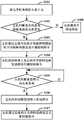
参阅附图6,图6示例性示出了本实施例中家电控制系统的供电控制装置的供电控制方法的主要步骤,如图6所示,本实施例中家电控制系统的供电控制装置的供电控制方法可以包括如下步骤:Referring to FIG. 6, FIG. 6 exemplarily shows the main steps of the power supply control method of the power supply control device of the home appliance control system in this embodiment. As shown in FIG. 6, the power supply of the power supply control device of the home appliance control system in this embodiment is The control method may include the following steps:
步骤S101,家电控制系统的主机上电。Step S101, the host of the home appliance control system is powered on.
步骤S102,主机判断是否向家电控制系统的从机供电。具体地,若主机判断出需要向从机供则转至步骤S103,若主机判断出不需要向从机供电则转至步骤S108。In step S102, the host determines whether to supply power to the slaves of the home appliance control system. Specifically, if the host determines that it is necessary to supply power to the slave, go to step S103, and if the host determines that it is not necessary to supply power to the slave, go to step S108.
步骤S103,主机通过总线向从机中电源控制模块的开关控制电路发送开通控制指令。具体地,当主机通过总线向开关控制电路发送开通控制指令后,开关控制电路可以根据开通控制指令控制电源控制模块的电源开关电路开通,以便电源能够通过高电平电源线向从机供电。Step S103, the host sends a turn-on control instruction to the switch control circuit of the power control module in the slave through the bus. Specifically, after the host sends a turn-on control command to the switch control circuit through the bus, the switch control circuit can control the power switch circuit of the power control module to turn on according to the turn-on control command, so that the power supply can supply power to the slave through the high-level power line.
例如,主机可以通过总线向图2所示的电源控制模块中的开关控制电路发送高电平信号,NPN型三极管在该高电平信号的驱动下导通,进而可以导通PNP型三极管,使得电源能够通过高电平电源线向从机供电。For example, the host can send a high-level signal to the switch control circuit in the power control module shown in Figure 2 through the bus, and the NPN transistor is turned on under the drive of the high-level signal, and then the PNP transistor can be turned on, so that The power supply can supply power to the slave through the high level power line.
步骤S104,从机的控制器上电后向开关控制电路发送维持开通控制指令。具体地,当从机得电后,其控制器向开关控制电路发送维持开通指令,以使开关控制电路根据维持开通控制指令控制电源开关电路维持在开通状态。Step S104, after the controller of the slave machine is powered on, it sends a maintain-on control instruction to the switch control circuit. Specifically, when the slave is powered on, its controller sends a keep-on instruction to the switch control circuit, so that the switch control circuit controls the power switch circuit to maintain an on state according to the keep-on control instruction.
例如,如图2所示的控制器向开关控制电路发送高电平信号,NPN型三极管在该高电平信号的驱动下导通,进而可以导通PNP型三极管,使得电源能够通过高电平电源线向从机供电。For example, the controller as shown in Figure 2 sends a high-level signal to the switch control circuit, and the NPN-type transistor is turned on under the drive of the high-level signal, and then the PNP-type transistor can be turned on, so that the power supply can pass the high-level signal. The power cord supplies power to the slave.
步骤S105,主机判断是否停止向从机供电。具体地,若主机判断出需要停止向从机供电,则转至步骤S106。若主机判断出不需要停止向从机供电,则继续判断是否停止向从机供电。Step S105, the master determines whether to stop supplying power to the slave. Specifically, if the master determines that it is necessary to stop supplying power to the slave, it will go to step S106. If the master determines that it is not necessary to stop supplying power to the slave, it continues to determine whether to stop supplying power to the slave.
步骤S106,主机向控制器发送停止供电指令。具体地,当从机的控制器接收到停止供电指令后即向控制电源开关电路停止维持开通状态,随后转至步骤S107。Step S106, the host sends an instruction to stop power supply to the controller. Specifically, when the controller of the slave machine receives the instruction to stop the power supply, it controls the power switch circuit to stop maintaining the ON state, and then goes to step S107 .
例如,主机向图2所示的控制器发送停止供电指令,当控制器接收到停止供电指令后,向NPN型三极管发送低电平信号。For example, the host sends a stop power supply instruction to the controller shown in FIG. 2 , and when the controller receives the power supply stop instruction, it sends a low-level signal to the NPN transistor.
步骤S107,主机通过总线向开关控制电路发送关断控制指令,以使开关控制电路根据关断控制指令控制电源开关电路关断,从而切断电源供电。Step S107, the host sends a shutdown control command to the switch control circuit through the bus, so that the switch control circuit controls the power switch circuit to be turned off according to the shutdown control command, thereby cutting off the power supply.
例如,主机向图2所示的控制器发送低电平信号,当控制器接收到低电平信号后,向NPN型三极管发送低电平信号,NPN型三极管不导通,进而使PNP型三极管不导通,从机断电。For example, the host sends a low-level signal to the controller shown in Figure 2. When the controller receives the low-level signal, it sends a low-level signal to the NPN-type transistor, and the NPN-type transistor does not conduct, thereby making the PNP-type transistor. No conduction, the slave is powered off.
步骤S108,从机维持不得电状态。In step S108, the slave maintains a power-off state.
上述实施例中虽然将各个步骤按照上述先后次序的方式进行了描述,但是本领域技术人员可以理解,为了实现本实施例的效果,不同的步骤之间不必按照这样的次序执行,其可以同时(并行)执行或以颠倒的次序执行,这些简单的变化都在本发明的保护范围之内。In the above-mentioned embodiment, although each step is described according to the above-mentioned order, those skilled in the art can understand that, in order to realize the effect of this embodiment, different steps need not be performed in this order, and it can be performed simultaneously ( parallel) or in reverse order, simple variations of these are within the scope of the present invention.
基于上述步骤,可以在不需要向从机供电时,如待机状态,休眠状态等,使从机彻底与电源断开连接,从而实现降低功耗的目的。Based on the above steps, the slave machine can be completely disconnected from the power supply when it is not necessary to supply power to the slave machine, such as a standby state, a sleep state, etc., so as to achieve the purpose of reducing power consumption.
下面结合附图4和5,对本发明提供的家电控制系统的供电控制装置的供电控制方法进行详细说明。4 and 5, the power supply control method of the power supply control device of the home appliance control system provided by the present invention will be described in detail.
在主机加电后,如果不需要向从机供电,则主机将总线设置为高电平,并在电阻R11和电阻R12作用下使PNP型三极管Q2关闭,此时开关指令接收电路接收到总线的低电平信号。NPN型三极管Q4的基极为低电平,NPN型三极管Q4不导通。此时在电阻R28的上拉作用下,使PNP型三极管Q1的基极的电平拉高,PNP型三极管Q1不导通。从机不得电。After the host is powered on, if it is not necessary to supply power to the slave, the host sets the bus to a high level, and turns off the PNP transistor Q2 under the action of the resistor R11 and the resistor R12. At this time, the switch command receiving circuit receives the bus signal. low level signal. The base of the NPN transistor Q4 is at a low level, and the NPN transistor Q4 does not conduct. At this time, under the pull-up action of the resistor R28, the level of the base of the PNP-type transistor Q1 is pulled up, and the PNP-type transistor Q1 is not turned on. No power from the machine.
如果需要向从机供电,则主机将总线设置为低电平,并在电阻R11和电阻R12作用下使PNP型三极管Q2导通,12V高电平通过电阻R14和第一二极管,使NPN型三极管Q4得到高电平信号,NPN型三极管Q4导通。在电阻R3的作用下,PNP型三极管Q1导通。12V高电平与+12V-CTL接通,从机得电。从机得电后,从机的控制器向NPN型三极管Q4发送维持开通控制指令(即高电平信号),维持NPN型三极管Q4的导通状态,使PNP型三极管Q1持续导通。此时,无论总线上的电平怎么变化,从机始终处于得电状态。If it is necessary to supply power to the slave, the master sets the bus to a low level, and turns on the PNP transistor Q2 under the action of the resistor R11 and the resistor R12, and the 12V high level passes through the resistor R14 and the first diode to make the NPN The NPN-type transistor Q4 gets a high-level signal, and the NPN-type transistor Q4 is turned on. Under the action of the resistor R3, the PNP transistor Q1 is turned on. The 12V high level is connected to +12V-CTL, and the slave is powered. After the slave is powered on, the controller of the slave sends a maintenance-on control command (ie, a high-level signal) to the NPN transistor Q4 to maintain the conduction state of the NPN transistor Q4, so that the PNP transistor Q1 continues to conduct. At this time, no matter how the level on the bus changes, the slave is always in the power-on state.
当需要停止向从机供电时,则主机向控制器发送停止供电指令,控制器根据接收到的停止供电控制指令向NPN型三极管Q4发送低电平信号,再将总线设置成高电平,并在电阻R11和电阻R12作用下使PNP型三极管Q2关闭,此时NPN型三极管Q4接收到分别来自控制器和总线的两个低电平信号,此时NPN型三极管Q4和PNP型三极管Q1均不导通。从机断电且处于低功耗模式。When it is necessary to stop power supply to the slave, the host sends a stop power supply command to the controller, and the controller sends a low level signal to the NPN transistor Q4 according to the received stop power supply control command, and then sets the bus to a high level, and Under the action of resistor R11 and resistor R12, the PNP transistor Q2 is turned off. At this time, the NPN transistor Q4 receives two low-level signals from the controller and the bus respectively. At this time, the NPN transistor Q4 and the PNP transistor Q1 are not connected. on. The slave is powered down and in a low power mode.
本领域的技术人员能够理解,尽管在此所述的一些实施例包括其它实施例中所包括的某些特征而不是其它特征,但是不同实施例的特征的组合意味着处于本发明的范围之内并且形成不同的实施例。例如,在本发明的权利要求书中,所要求保护的实施例的任意之一都可以以任意的组合方式来使用。It will be understood by those skilled in the art that although some of the embodiments described herein include certain features, but not others, included in other embodiments, that combinations of features of the different embodiments are intended to be within the scope of the present invention And form different embodiments. For example, in the claims of this invention, any of the claimed embodiments may be used in any combination.
本发明还可以实现为用于执行这里所描述的方法的一部分或者全部的设备或者装置程序(例如,PC程序和PC程序产品)。这样的实现本发明的程序可以存储在PC可读介质上,或者可以具有一个或者多个信号的形式。这样的信号可以从因特网网站上下载得到,或者在载体信号上提供,或者以任何其他形式提供。The present invention may also be implemented as a device or apparatus program (eg, PC programs and PC program products) for performing part or all of the methods described herein. Such a program implementing the present invention may be stored on a PC-readable medium, or may be in the form of one or more signals. Such signals may be downloaded from Internet sites, or provided on carrier signals, or in any other form.
应该注意的是上述实施例对本发明进行说明而不是对本发明进行限制,并且本领域技术人员在不脱离所附权利要求的范围的情况下可设计出替换实施例。在权利要求中,单词“包括”不排除存在未列在权利要求中的元件或步骤。位于元件之前的单词“一”或“一个”不排除存在多个这样的元件。本发明可以借助于包括有若干不同元件的硬件以及借助于适当编程的PC来实现。单词第一和第二的使用不表示任何顺序,可将这些单词解释为名称。It should be noted that the above-described embodiments illustrate rather than limit the invention, and that alternative embodiments may be devised by those skilled in the art without departing from the scope of the appended claims. In the claims, the word "comprising" does not exclude the presence of elements or steps not listed in the claims. The word "a" or "an" preceding an element does not exclude the presence of a plurality of such elements. The invention can be implemented by means of hardware comprising several different elements and by means of a suitably programmed PC. The use of the words first and second does not denote any order and these words can be interpreted as names.
至此,已经结合附图所示的优选实施方式描述了本发明的技术方案,但是,本领域技术人员容易理解的是,本发明的保护范围显然不局限于这些具体实施方式。在不偏离本发明的原理的前提下,本领域技术人员可以对相关技术特征作出等同的更改或替换,这些更改或替换之后的技术方案都将落入本发明的保护范围之内。So far, the technical solutions of the present invention have been described with reference to the preferred embodiments shown in the accompanying drawings, however, those skilled in the art can easily understand that the protection scope of the present invention is obviously not limited to these specific embodiments. Without departing from the principle of the present invention, those skilled in the art can make equivalent changes or substitutions to the relevant technical features, and the technical solutions after these changes or substitutions will fall within the protection scope of the present invention.
Claims (10)
Translated fromChinesePriority Applications (1)
| Application Number | Priority Date | Filing Date | Title |
|---|---|---|---|
| CN201910064447.8ACN111474871B (en) | 2019-01-23 | 2019-01-23 | Power supply control device and method for home appliance control system |
Applications Claiming Priority (1)
| Application Number | Priority Date | Filing Date | Title |
|---|---|---|---|
| CN201910064447.8ACN111474871B (en) | 2019-01-23 | 2019-01-23 | Power supply control device and method for home appliance control system |
Publications (2)
| Publication Number | Publication Date |
|---|---|
| CN111474871Atrue CN111474871A (en) | 2020-07-31 |
| CN111474871B CN111474871B (en) | 2022-12-09 |
Family
ID=71743793
Family Applications (1)
| Application Number | Title | Priority Date | Filing Date |
|---|---|---|---|
| CN201910064447.8AActiveCN111474871B (en) | 2019-01-23 | 2019-01-23 | Power supply control device and method for home appliance control system |
Country Status (1)
| Country | Link |
|---|---|
| CN (1) | CN111474871B (en) |
Cited By (1)
| Publication number | Priority date | Publication date | Assignee | Title |
|---|---|---|---|---|
| CN112099861A (en)* | 2020-09-16 | 2020-12-18 | 上海闻泰信息技术有限公司 | Terminal management method, device, user terminal and computer readable storage medium |
Citations (13)
| Publication number | Priority date | Publication date | Assignee | Title |
|---|---|---|---|---|
| US5170491A (en)* | 1988-05-13 | 1992-12-08 | Nec Corporation | Power source switch circuit |
| CN101594171A (en)* | 2009-06-25 | 2009-12-02 | 浙江大学 | A power line chopping communication transceiver circuit |
| CN103529723A (en)* | 2013-10-30 | 2014-01-22 | 中国兵器工业集团第二一四研究所苏州研发中心 | Triggering jitter prevention time switch circuit with zero static power consumption |
| CN203522260U (en)* | 2013-10-11 | 2014-04-02 | Tcl通力电子(惠州)有限公司 | Cell power-supplying control circuit and a double-power-supply power supplying device |
| CN204557082U (en)* | 2015-01-14 | 2015-08-12 | 北京长城华冠汽车科技有限公司 | Pure electric vehicle controller power waken system and power supply wake-up circuit |
| CN104850023A (en)* | 2015-05-12 | 2015-08-19 | 广东美的制冷设备有限公司 | Current loop communication and power supply control circuit of air conditioner and outdoor unit and method thereof |
| CN106773959A (en)* | 2016-12-16 | 2017-05-31 | 深圳创维空调科技有限公司 | A kind of light current for being based on the communication of two heart yearns wakes up system and method |
| CN206907210U (en)* | 2017-05-17 | 2018-01-19 | 广州华凌制冷设备有限公司 | Air conditioner communicating circuit |
| CN107681707A (en)* | 2016-10-17 | 2018-02-09 | 深圳市东方之星电源有限公司 | A kind of automobile and automobile power supply system dormancy control circuit |
| CN107696993A (en)* | 2017-10-18 | 2018-02-16 | 深圳市信丰伟业科技有限公司 | External vehicle-mounted equipment protection circuit and control method |
| CN207523615U (en)* | 2017-12-08 | 2018-06-22 | 深圳创维汽车智能有限公司 | Vehicle power supply power supply circuit and vehicle communication terminal |
| CN207955543U (en)* | 2018-01-29 | 2018-10-12 | 杭州高特新能源技术有限公司 | A kind of MCU module Low-power-consumptiodormancy dormancy circuit |
| CN208325119U (en)* | 2018-03-21 | 2019-01-04 | 厦门歌乐电子企业有限公司 | A kind of bus control circuit, mobile unit and onboard system |
- 2019
- 2019-01-23CNCN201910064447.8Apatent/CN111474871B/enactiveActive
Patent Citations (13)
| Publication number | Priority date | Publication date | Assignee | Title |
|---|---|---|---|---|
| US5170491A (en)* | 1988-05-13 | 1992-12-08 | Nec Corporation | Power source switch circuit |
| CN101594171A (en)* | 2009-06-25 | 2009-12-02 | 浙江大学 | A power line chopping communication transceiver circuit |
| CN203522260U (en)* | 2013-10-11 | 2014-04-02 | Tcl通力电子(惠州)有限公司 | Cell power-supplying control circuit and a double-power-supply power supplying device |
| CN103529723A (en)* | 2013-10-30 | 2014-01-22 | 中国兵器工业集团第二一四研究所苏州研发中心 | Triggering jitter prevention time switch circuit with zero static power consumption |
| CN204557082U (en)* | 2015-01-14 | 2015-08-12 | 北京长城华冠汽车科技有限公司 | Pure electric vehicle controller power waken system and power supply wake-up circuit |
| CN104850023A (en)* | 2015-05-12 | 2015-08-19 | 广东美的制冷设备有限公司 | Current loop communication and power supply control circuit of air conditioner and outdoor unit and method thereof |
| CN107681707A (en)* | 2016-10-17 | 2018-02-09 | 深圳市东方之星电源有限公司 | A kind of automobile and automobile power supply system dormancy control circuit |
| CN106773959A (en)* | 2016-12-16 | 2017-05-31 | 深圳创维空调科技有限公司 | A kind of light current for being based on the communication of two heart yearns wakes up system and method |
| CN206907210U (en)* | 2017-05-17 | 2018-01-19 | 广州华凌制冷设备有限公司 | Air conditioner communicating circuit |
| CN107696993A (en)* | 2017-10-18 | 2018-02-16 | 深圳市信丰伟业科技有限公司 | External vehicle-mounted equipment protection circuit and control method |
| CN207523615U (en)* | 2017-12-08 | 2018-06-22 | 深圳创维汽车智能有限公司 | Vehicle power supply power supply circuit and vehicle communication terminal |
| CN207955543U (en)* | 2018-01-29 | 2018-10-12 | 杭州高特新能源技术有限公司 | A kind of MCU module Low-power-consumptiodormancy dormancy circuit |
| CN208325119U (en)* | 2018-03-21 | 2019-01-04 | 厦门歌乐电子企业有限公司 | A kind of bus control circuit, mobile unit and onboard system |
Cited By (2)
| Publication number | Priority date | Publication date | Assignee | Title |
|---|---|---|---|---|
| CN112099861A (en)* | 2020-09-16 | 2020-12-18 | 上海闻泰信息技术有限公司 | Terminal management method, device, user terminal and computer readable storage medium |
| CN112099861B (en)* | 2020-09-16 | 2024-07-23 | 上海闻泰信息技术有限公司 | Terminal management method, device, user terminal and computer readable storage medium |
Also Published As
| Publication number | Publication date |
|---|---|
| CN111474871B (en) | 2022-12-09 |
Similar Documents
| Publication | Publication Date | Title |
|---|---|---|
| CN110008069B (en) | Power switching control circuit and control method | |
| CN100499766C (en) | Quick starting TV set capable of implementing standby low power dissipation | |
| US9170618B2 (en) | Power management circuit, server, and power management method thereof | |
| CN103425235A (en) | Single chip microcomputer low power consumption standby circuit and control method | |
| JP2011108235A (en) | Peripheral device, power-saving circuit for switching device, and operation method | |
| CN103078406A (en) | Power-grid-based power strip control system and method | |
| US20210365101A1 (en) | Control system for controlling intelligent system to reduce power consumption based on bluetooth device | |
| CN111474871B (en) | Power supply control device and method for home appliance control system | |
| CN113938333B (en) | Power over Ethernet device and system | |
| CN108488948B (en) | Air conditioner, air conditioner control system and outdoor unit switch circuit | |
| CN113282036A (en) | Communication control device and method of HBS (hybrid bus system) and multi-split system | |
| CN218549882U (en) | Controller power supply circuit and electrical equipment | |
| CN215773129U (en) | Underwater sound communication equipment | |
| CN209514545U (en) | Applied to the overheating protection circuit and high-performance server on high-performance server | |
| CN207689874U (en) | Microcontroller automatic shutdown circuitry | |
| CN108540122B (en) | A communication interface circuit | |
| CN211603886U (en) | WiFi module control circuit, device thereof and electrical equipment | |
| WO2021073050A1 (en) | Switch circuit, motor control system, and vacuum cleaner | |
| CN205193723U (en) | Electric system in hard disk timesharing | |
| CN109710011A (en) | A kind of low-power consumption dummy load circuit | |
| CN219086871U (en) | Power switching circuits and electrical appliances | |
| US11797471B2 (en) | System and method for controlling a computer to receive external data for out-of-band management | |
| CN115642908A (en) | Controller power supply circuit and electrical equipment | |
| CN120275868B (en) | Device plug-in detection and error reporting device and method | |
| CN110943527B (en) | power supply device |
Legal Events
| Date | Code | Title | Description |
|---|---|---|---|
| PB01 | Publication | ||
| PB01 | Publication | ||
| SE01 | Entry into force of request for substantive examination | ||
| SE01 | Entry into force of request for substantive examination | ||
| CB02 | Change of applicant information | ||
| CB02 | Change of applicant information | Address after:266101 Haier Industrial Park, 1 Haier Road, Laoshan District, Shandong, Qingdao Applicant after:QINGDAO HAIER WASHING MACHINE Co.,Ltd. Applicant after:Haier Smart Home Co., Ltd. Address before:266101 Haier Industrial Park, 1 Haier Road, Laoshan District, Shandong, Qingdao Applicant before:QINGDAO HAIER WASHING MACHINE Co.,Ltd. Applicant before:QINGDAO HAIER JOINT STOCK Co.,Ltd. | |
| GR01 | Patent grant | ||
| GR01 | Patent grant |