CN111470088A - An automatic adjustment type bottle divider - Google Patents
An automatic adjustment type bottle dividerDownload PDFInfo
- Publication number
- CN111470088A CN111470088ACN202010262155.8ACN202010262155ACN111470088ACN 111470088 ACN111470088 ACN 111470088ACN 202010262155 ACN202010262155 ACN 202010262155ACN 111470088 ACN111470088 ACN 111470088A
- Authority
- CN
- China
- Prior art keywords
- channel
- bottle
- rotating
- blocking
- lane
- Prior art date
- Legal status (The legal status is an assumption and is not a legal conclusion. Google has not performed a legal analysis and makes no representation as to the accuracy of the status listed.)
- Granted
Links
- 230000007246mechanismEffects0.000claimsabstractdescription78
- 230000000903blocking effectEffects0.000claimsdescription56
- 238000001514detection methodMethods0.000claimsdescription47
- 230000001360synchronised effectEffects0.000claimsdescription12
- 238000013519translationMethods0.000claimsdescription12
- 230000007704transitionEffects0.000claimsdescription8
- 210000001503jointAnatomy0.000claimsdescription4
- 238000007665saggingMethods0.000claims1
- 238000000926separation methodMethods0.000abstractdescription27
- 238000012856packingMethods0.000abstractdescription4
- 238000000034methodMethods0.000description3
- 230000005540biological transmissionEffects0.000description2
- 239000013072incoming materialSubstances0.000description2
- 230000035515penetrationEffects0.000description2
- 230000008569processEffects0.000description2
- 230000009286beneficial effectEffects0.000description1
- 230000007547defectEffects0.000description1
- 238000011161developmentMethods0.000description1
- 238000010586diagramMethods0.000description1
- 238000003780insertionMethods0.000description1
- 230000037431insertionEffects0.000description1
- 238000003032molecular dockingMethods0.000description1
- 230000002265preventionEffects0.000description1
- 238000012546transferMethods0.000description1
Images


Classifications
- B—PERFORMING OPERATIONS; TRANSPORTING
- B65—CONVEYING; PACKING; STORING; HANDLING THIN OR FILAMENTARY MATERIAL
- B65B—MACHINES, APPARATUS OR DEVICES FOR, OR METHODS OF, PACKAGING ARTICLES OR MATERIALS; UNPACKING
- B65B21/00—Packaging or unpacking of bottles
- B65B21/02—Packaging or unpacking of bottles in or from preformed containers, e.g. crates
- B65B21/04—Arranging, assembling, feeding, or orientating the bottles prior to introduction into, or after removal from, containers
- B65B21/06—Forming groups of bottles
- Y—GENERAL TAGGING OF NEW TECHNOLOGICAL DEVELOPMENTS; GENERAL TAGGING OF CROSS-SECTIONAL TECHNOLOGIES SPANNING OVER SEVERAL SECTIONS OF THE IPC; TECHNICAL SUBJECTS COVERED BY FORMER USPC CROSS-REFERENCE ART COLLECTIONS [XRACs] AND DIGESTS
- Y02—TECHNOLOGIES OR APPLICATIONS FOR MITIGATION OR ADAPTATION AGAINST CLIMATE CHANGE
- Y02W—CLIMATE CHANGE MITIGATION TECHNOLOGIES RELATED TO WASTEWATER TREATMENT OR WASTE MANAGEMENT
- Y02W30/00—Technologies for solid waste management
- Y02W30/50—Reuse, recycling or recovery technologies
- Y02W30/62—Plastics recycling; Rubber recycling
Landscapes
- Engineering & Computer Science (AREA)
- Mechanical Engineering (AREA)
- Specific Conveyance Elements (AREA)
- Attitude Control For Articles On Conveyors (AREA)
Abstract
Translated fromChinese
Description
Translated fromChinese技术领域technical field
本发明涉及瓶类装箱技术领域,具体涉及一种自动调节型分瓶机。The invention relates to the technical field of bottle packing, in particular to an automatic adjustment type bottle separator.
背景技术Background technique
在现代科技的飞速发展下,提高设备使用效率,是现代化企业降低生产成本,增加效率的理想途径,其带来的一系列效益也十分可观。Under the rapid development of modern science and technology, improving the efficiency of equipment use is an ideal way for modern enterprises to reduce production costs and increase efficiency, and a series of benefits it brings are also very considerable.
而在生产企业中,瓶装类产品装箱,单一产品类分瓶设备比较普遍,市场有单一瓶装类产品分瓶类设备,这就意味着同一流水线只能生产一种瓶装类产品,大大降低了设备使用率。传统的瓶装类产品装箱,整条输送线只能生产同一类尺寸瓶装类产品,不能更换,不仅减少了设备使用效率,还使得生产效率大大降低。In production enterprises, bottled products are packed into boxes, and single-product bottle sorting equipment is relatively common. There are single bottled product sorting equipment in the market, which means that the same assembly line can only produce one type of bottled product, which greatly reduces the cost of equipment usage. Traditional bottled products are boxed, and the entire conveying line can only produce bottled products of the same size and cannot be replaced, which not only reduces the efficiency of equipment use, but also greatly reduces production efficiency.
发明内容SUMMARY OF THE INVENTION
本发明要解决的技术问题是,针对现有技术存在的上述缺陷,提供了一种自动调节型分瓶机,实现了瓶类产品的自动分瓶排列,从而便于抓取装箱。提高了设备使用率,生产效率得到了有效提升。The technical problem to be solved by the present invention is, in view of the above-mentioned defects in the prior art, an automatic adjustment type bottle separator is provided, which realizes the automatic bottle separation and arrangement of bottle products, thereby facilitating grasping and packing. The equipment utilization rate has been improved, and the production efficiency has been effectively improved.
本发明为解决上述技术问题所采用的技术方案是:The technical scheme adopted by the present invention for solving the above-mentioned technical problems is:
一种自动调节型分瓶机,其特征在于,包括分道装置、导向装置和输送装置;分道装置和导向装置依次架设于输送装置上方;分道装置的输出端与导向装置的输入端对接;An automatic adjustment type bottle separator is characterized in that it comprises a lane dividing device, a guiding device and a conveying device; the lane dividing device and the guiding device are erected above the conveying device in sequence; the output end of the lane dividing device is butted with the input end of the guiding device ;
导向装置包括多个并排布置的分道通道,分道装置包括活动通道和旋转机构,旋转机构与活动通道连接,带动活动通道转动,使活动通道的输出端与不同分道通道的输入端对接。The guide device includes a plurality of side-by-side channel separation channels. The channel separation device includes a movable channel and a rotating mechanism. The rotating mechanism is connected with the movable channel to drive the movable channel to rotate, so that the output end of the movable channel is connected with the input ends of different channel separation channels.
旋转机构包括摆动轴、第一固定支架和驱动单元,第一固定支架架设于输送装置上,驱动单元设置于第一固定支架上,摆动轴的一端铰接于第一固定支架上,摆动轴的另一端与驱动单元连接,活动通道的上端与摆动轴连接,驱动单元带动摆动轴以铰接点为中心摆动,使活动通道随摆动轴绕铰接点转动。The rotation mechanism includes a swing shaft, a first fixed bracket and a driving unit. The first fixed bracket is erected on the conveying device, the drive unit is arranged on the first fixed bracket, one end of the swing shaft is hinged on the first fixed bracket, and the other One end is connected with the drive unit, the upper end of the movable channel is connected with the swing shaft, the drive unit drives the swing shaft to swing around the hinge point, so that the movable channel rotates around the hinge point with the swing shaft.
按上述技术方案,驱动单元包括横向平移装置、转动块和滑杆,转动块与横向平移装置连接,转动块上设有通孔,滑杆的一端套接于转动块的通孔内,滑杆可沿转动块的通孔纵向滑移,摆动轴与滑杆的另一端连接;横向平移装置带动转动块横向来回移动,转动块横移带动滑杆摆动,进而通过滑杆带动摆动轴摆动,转动块带动滑杆摆动的同时滑杆沿转动块的通孔纵向移动。According to the above technical solution, the driving unit includes a lateral translation device, a rotating block and a sliding rod. The rotating block is connected to the lateral translation device. The rotating block is provided with a through hole, and one end of the sliding rod is sleeved in the through hole of the rotating block. It can slide longitudinally along the through hole of the rotating block, and the swing shaft is connected with the other end of the sliding rod; the lateral translation device drives the rotating block to move back and forth laterally, the lateral movement of the rotating block drives the sliding rod to swing, and then the sliding rod drives the swing shaft to swing and rotate. When the block drives the sliding rod to swing, the sliding rod moves longitudinally along the through hole of the rotating block.
按上述技术方案,横向平移装置包括同步带、两个带轮、电机和移动块,两个带轮设置于第一固定架上,分别布设于摆动轴的两侧,两个带轮之间通过同步带连接,电机与其中一个带轮连接,并固设于第一固定架上,移动块与同步带连接;电机驱动带轮通过同步带带动移动块横向来回移动,转动块与移动块转动连接。According to the above technical solution, the lateral translation device includes a synchronous belt, two pulleys, a motor and a moving block. The two pulleys are arranged on the first fixing frame and are respectively arranged on both sides of the swing shaft. The synchronous belt is connected, the motor is connected with one of the pulleys, and is fixed on the first fixing frame, and the moving block is connected with the synchronous belt; the motor drives the pulley to drive the moving block to move back and forth laterally through the synchronous belt, and the rotating block is connected with the moving block. .
按上述技术方案,活动通道与旋转机构之间设有第一调节机构,第一调节机构设置于第一固定架上,活动通道包括两块相对并排布置的夹板,第一调节机构分别与两个夹板连接,第一调节机构用于调节活动通道的两个夹板之间的间距;从而调节活动通道的通道宽度。According to the above technical solution, a first adjustment mechanism is arranged between the movable channel and the rotating mechanism, the first adjustment mechanism is arranged on the first fixed frame, the movable channel includes two splints arranged oppositely side by side, and the first adjustment mechanism is respectively connected with the two The splints are connected, and the first adjustment mechanism is used to adjust the distance between the two splints of the movable channel; thereby adjusting the channel width of the movable channel.
按上述技术方案,分道装置还包括自动计数检测装置和夹持机构;自动计数检测装置和夹持机构均设置于活动通道的输出端。According to the above technical solution, the lane separation device further includes an automatic counting detection device and a clamping mechanism; the automatic counting detection device and the clamping mechanism are both arranged at the output end of the movable channel.
按上述技术方案,导向装置还包括第二固定支架、阻挡机构和推瓶机构,第二固定支架固设于输送装置上,分道通道的上端与第二固定支架连接,阻挡机构设置于每个分道通道内,推瓶机构设置于每个分道通道的输出端。According to the above technical solution, the guiding device further includes a second fixing bracket, a blocking mechanism and a bottle pushing mechanism. In the channel, the bottle pushing mechanism is arranged at the output end of each channel.
按上述技术方案,每个分道通道上均设有倒瓶检测装置,倒瓶检测装置布置于阻挡机构的前方;倒瓶检测装置包括检测杆、转轴和传感器,转轴横向布置于第二固定支架上,检测杆通过转轴设置于第二固定支架上,检测杆可绕转轴转动,传感器设置于转轴上,传动器用于检测检测杆的转动角度,当检测杆竖直下垂状态时,检测杆的最下端低于输送瓶子的最高点。According to the above technical solution, each channel is provided with a bottle inversion detection device, and the bottle inversion detection device is arranged in front of the blocking mechanism; the bottle inversion detection device includes a detection rod, a rotating shaft and a sensor, and the rotating shaft is horizontally arranged on the second fixed bracket The detection rod is set on the second fixed bracket through the rotating shaft, the detection rod can rotate around the rotating shaft, the sensor is arranged on the rotating shaft, and the transmission is used to detect the rotation angle of the detection rod. The lower end is lower than the highest point of the conveying bottle.
按上述技术方案,输送装置包括链板输送机和整列输送机,活动通道设置于链板输送机上方,分道通道的输入端设置于链板输送机上方;分道通道的输出端设置于整列输送机上方,整列输送机的速度大于链板输送机;According to the above technical scheme, the conveying device includes a chain plate conveyor and an entire row conveyor, the movable channel is arranged above the chain plate conveyor, the input end of the sub-channel is arranged above the chain plate conveyor; the output end of the sub-channel channel is arranged above the chain plate conveyor; Above the conveyor, the speed of the entire conveyor is greater than that of the chain conveyor;
链板输送机和整列输送机的对接处设置有过渡链板,阻挡机构设置于过渡链板上方。A transition chain plate is arranged at the butt joint of the chain plate conveyor and the whole-row conveyor, and the blocking mechanism is arranged above the transition chain plate.
按上述技术方案,阻挡机构包括阻挡气缸和两个竖直平行并排布置的挡杆,阻挡气缸固设于第二固定支架上,阻挡气缸的活塞杆通过连接块与两个挡杆连接,带动两个挡杆上下移动;According to the above technical solution, the blocking mechanism includes a blocking cylinder and two blocking rods arranged vertically parallel and side by side, the blocking cylinder is fixed on the second fixing bracket, and the piston rod of the blocking cylinder is connected with the two blocking rods through a connecting block to drive the two blocking rods. A stop lever moves up and down;
所述的被输送瓶子的横截面为圆形,两个挡杆之间的距离小于被输送瓶子的最大横截面直径,两个挡杆分别竖直布置于分道通道纵向输送中心线的两侧。The cross section of the bottle to be conveyed is circular, the distance between the two blocking bars is less than the maximum cross-sectional diameter of the bottle to be conveyed, and the two blocking bars are vertically arranged on both sides of the longitudinal conveying center line of the lane separation channel. .
本发明具有以下有益效果:The present invention has the following beneficial effects:
1、实现了瓶类产品的自动分瓶排列,从而便于抓取装箱。提高了设备使用率,生产效率得到了有效提升。1. The automatic sorting and arrangement of bottle products is realized, which is convenient for grabbing and packing. The equipment utilization rate has been improved, and the production efficiency has been effectively improved.
2、实现了不同直径、高度尺寸瓶类产品的分瓶排列,也可实现对多个品种瓶装类产品进行分拣整理排列,一体化程度高,工作效率高,可实现多规格瓶装类产品分瓶,兼容性好,节约设备成本,可以适用不同尺寸大小的瓶装类产品;能够调节通道间距以适应不同种类瓶子,并具有计数、倒瓶检测、精准分道功能,提高设备使用效率,达到一机多产的目的。2. It realizes the sorting and arrangement of bottled products of different diameters and heights, and can also realize the sorting and arrangement of multiple varieties of bottled products. Bottles have good compatibility, save equipment costs, and can be applied to bottled products of different sizes; the channel spacing can be adjusted to suit different types of bottles, and it has the functions of counting, inverted bottle detection, and accurate channel separation, improving equipment use efficiency and achieving a machine for productive purposes.
附图说明Description of drawings
图1是本发明中所述的一种自动调节型分瓶机的整体结构示意图;Fig. 1 is the overall structure schematic diagram of a kind of automatic adjustment type bottle separator described in the present invention;
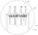
图2是本发明中所述的分道装置的结构示意图;Fig. 2 is the structural representation of the lane dividing device described in the present invention;
图3是本发明中所述的分道装置的正视图;Fig. 3 is the front view of the lane dividing device described in the present invention;
图4是本发明中所述的导向装置的结构示意图;Fig. 4 is the structural representation of the guide device described in the present invention;
图5是本发明中所述的导向装置的俯视图;Fig. 5 is the top view of the guide device described in the present invention;
图6是本发明中所述的导向装置的K向局部剖视图;Fig. 6 is the K-direction partial sectional view of the guide device described in the present invention;
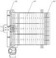
图7是本发明中所述的输送装置的结构示意图;Fig. 7 is the structural representation of the conveying device described in the present invention;
图8是本发明中所述的输送装置的局部俯视图;Figure 8 is a partial top view of the conveying device described in the present invention;
图中,100-瓶子,200-分道装置,201-第一固定支架,202-摆动横梁,203-摆动轴,204-第一调节机构,205-夹板,206-伺服电机,207-带轮,208-移动块,209-转动块,210-滑杆,211-同步带,212-夹持气缸;In the figure, 100-bottle, 200-lane separation device, 201-first fixing bracket, 202-swing beam, 203-swing shaft, 204-first adjusting mechanism, 205- splint, 206-servo motor, 207-belt pulley , 208 - moving block, 209 - rotating block, 210 - sliding rod, 211 - timing belt, 212 - clamping cylinder;
300-导向装置,301-第二固定支架,302-第二调节机构,303-阻挡机构,304-分道板,305-倒瓶检测装置,306-挡杆;300-guide device, 301-second fixing bracket, 302-second adjustment mechanism, 303-blocking mechanism, 304-channel plate, 305-inversion detection device, 306-blocking rod;
410-链板输送机,420-整列输送机,430-推瓶机构,440-过渡链板。410-chain plate conveyor, 420-line conveyor, 430-bottle push mechanism, 440-transition chain plate.
具体实施方式Detailed ways
下面结合附图和实施例对本发明进行详细说明。The present invention will be described in detail below with reference to the accompanying drawings and embodiments.
参照图1~图8所示,本发明提供的一种实施例中提供了一种自动调节型分瓶机,其特征在于,包括分道装置200、导向装置300和输送装置;分道装置200和导向装置300依次架设于输送装置上方;分道装置200的输出端与导向装置300的输入端对接;1 to 8, an embodiment provided by the present invention provides an automatic adjustment type bottle separator, which is characterized in that it includes a
导向装置300包括多个并排布置的分道通道,分道装置200包括活动通道和旋转机构,旋转机构与活动通道连接,带动活动通道转动,使活动通道的输出端与不同分道通道的输入端对接;活动通道的输入端与前端输入装置对接。The
进一步地,旋转机构包括摆动轴203、第一固定支架201和驱动单元,第一固定支架201架设于输送装置上,驱动单元设置于第一固定支架201上,摆动轴203的一端铰接于第一固定支架201上,摆动轴203的另一端与驱动单元连接,活动通道的上端与摆动轴203连接,驱动单元带动摆动轴203以铰接点为中心摆动,使活动通道随摆动轴203绕铰接点转动。Further, the rotating mechanism includes a swinging
进一步地,第一固定支架201上设有摆动横梁202,摆动横梁202横架于输送装置上方,摆动轴203的一端与摆动横梁202铰接,摆动轴203的另一端与驱动单元连接。Further, the
进一步地,驱动单元包括横向平移装置、转动块209和滑杆210,转动块209与横向平移装置连接,转动块209上沿输送方向设有通孔,滑杆210的一端套接于转动块209的通孔内,滑杆210可沿转动块209的通孔纵向滑移,摆动轴203与滑杆210的另一端连接;横向平移装置带动转动块209横向来回移动,转动块209横移带动滑杆210摆动,进而通过滑杆210带动摆动轴203摆动,转动块209带动滑杆210摆动的同时滑杆210沿转动块209的通孔纵向移动。Further, the driving unit includes a lateral translation device, a rotating block 209 and a sliding rod 210, the rotating block 209 is connected with the lateral translation device, the rotating block 209 is provided with a through hole along the conveying direction, and one end of the sliding rod 210 is sleeved on the rotating block 209 The sliding rod 210 can slide longitudinally along the through hole of the rotating block 209, and the
进一步地,横向平移装置包括同步带211、两个带轮207、电机和移动块208,两个带轮207设置于第一固定架上,分别布设于摆动轴203的两侧,两个带轮207之间通过同步带211连接,电机与其中一个带轮207连接,并固设于第一固定架上,移动块208与同步带211连接;电机驱动带轮207通过同步带211带动移动块208横向来回移动,转动块209与移动块208转动连接。Further, the lateral translation device includes a
进一步地,电机为伺服电机206。Further, the motor is a
进一步地,转动块209通过轴承设置于移动块208上,两个带轮207所在直线与瓶子的输送方向垂直。Further, the rotating block 209 is arranged on the moving
进一步地,活动通道与旋转机构之间设有第一调节机构204,第一调节机构设置于第一固定架上,活动通道包括两块相对并排布置的夹板205,第一调节机构204分别与两个夹板205连接,第一调节机构204用于调节活动通道的两个夹板205之间的间距;从而调节活动通道的通道宽度。Further, a
进一步地,第一调节机构204包括第一调节气缸,第一调节气缸的两端分别与两个夹板205连接,第一调节气缸伸缩调节控制调节两个夹板205之间的距离,从而调节活动通道的宽度。Further, the
进一步地,分道装置200还包括自动计数检测装置和夹持机构;自动计数检测装置和夹持机构均设置于活动通道的输出端。Further, the
进一步地,夹持机构包括两个夹持气缸212,两个夹持气缸212分别设置于两个夹板205上,并且相对布置;夹持气缸212的活塞杆连接有夹持板,两个夹持气缸212相对伸出,通过两个夹持板对活动通道内的瓶子夹紧,摆动轴203带动活动通道摆动至与相应的分道通道对接后,两个夹持气缸212回缩放开对瓶子的夹持,活动通道内的瓶子进入至相应的分道通道内,自动计数检测装置用于计数从活动通道输出的瓶子个数,以及进入不同分道通道的瓶子个数,摆动轴203的铰接点上设有传感器,传感器用于检测摆动轴203的摆动角度。Further, the clamping mechanism includes two clamping
进一步地,旋转机构的输入端设置有摆动横梁202;所述旋转机构的输入端设置有一球形凹槽;所述摆动横梁202中部相应设置有一球形凸起;所述凸起嵌入凹槽使得旋转机构的输入端固定于凸起处,输出端以凸起为圆心旋转摆动。所述摆动横梁202两端连接有第一固定支架201;所述夹板205的输出端设置有夹持机构;在摆动换道的过程中,夹住出口处瓶子,使其不被甩出,保证其不脱离夹板205的夹持范围。两侧夹板205以摆轴为中心,对称分布。Further, the input end of the rotating mechanism is provided with a
进一步地,导向装置300还包括第二固定支架301、阻挡机构303和推瓶机构430,第二固定支架301固设于输送装置上,分道通道的上端与第二固定支架301连接,阻挡机构303设置于每个分道通道内,推瓶机构430设置于每个分道通道的输出端,阻挡机构303和推瓶机构430均与第二固定支架301连接固定。Further, the
进一步地,多个并排布置的分道通道由多个相互平行布置的分道板304组成,每相邻两个分道板304之间形成一个分道通道,每个分道通道与第二固定支架301之间均连接有第二调节机构302,第二调节机构302固设于第二固定支架301上,第二调节机构302的两端分别与相应的两个相邻分道板304连接,第二调节机构302用于调节活动通道的两个分道板304之间的间距;从而调节分道通道的通道宽度。Further, the plurality of side-by-side channel separation channels are composed of a plurality of
进一步地,第二调节机构302包括调节气缸,调节气缸固设于第二固定支架301上,调节气缸的两端分别与两个分道板304连接。Further, the
进一步地,分道板304的数量为3~6块,可根据实际生产需要进行分道板304数目的调节。Further, the number of the
进一步地,每个分道通道上均设有倒瓶检测装置305,倒瓶检测装置305布置于阻挡机构303的前方(此处所指前方是输送来料方向);倒瓶检测装置305包括检测杆、转轴和传感器,转轴横向布置于第二固定支架301上(转轴所述的横向是指转轴的长度方向与分道通道的输送方向横向垂直),检测杆通过转轴设置于第二固定支架301上,检测杆可绕转轴转动,传感器设置于转轴上,传动器用于检测检测杆的转动角度,当检测杆竖直下垂状态时,检测杆的最下端低于输送瓶子的最高点;当分道通道中没有物品输送通过时,检测杆呈竖直下垂,当分道通道有输送瓶子通过时,将检测杆向前顶起,并使检测杆旋转至相应的角度,检测杆并不影响瓶子的输送通过,当分道通道上输送歪倒的瓶子时,也将检测杆向前顶起,但检测杆旋转至的角度小于正常瓶子通过时旋转起的角度,通过传感器检测检测杆到达的角度即可判断分道通道内是输送正常状态的瓶子、歪倒状态的瓶子或无瓶子通过状态。Further, each channel is provided with a bottle
进一步地,分道装置200还包括自动计数检测装置;所述自动计数检测装置设置于分道装置200的输出端,自动计数检测装置可以检测高度不同产品的数量。所述导向装置300还包括倒瓶检测装置305;所述倒瓶检测装置305设置于导向装置300的输入端。所述倒瓶检测系统用于检测瓶子是否正常放置和计算每一通道内瓶子数量。Further, the
进一步地,输送装置包括链板输送机410和整列输送机420,活动通道200设置于链板输送机410上方,分道通道300的输入端设置于链板输送机410上方;分道通道的输出端设置于整列输送机420上方,整列输送机420的速度略大于链板输送机410;整列输送机420和链板输送机410具有单独的动力和控制单元,且整列输送机420的速度略大于链板输送机410,便于分开控制和防止堆瓶,使整列输送机420上待抓取瓶子与链板输送机410瓶子分开。Further, the conveying device includes a
链板输送机410和整列输送机420的对接处设置有过渡链板440,阻挡机构303设置于过渡链板440上方;所述导向装置300以阻挡机构303为界,输入端一侧固定于连板输送机上方,输出端一侧固定于整列输送机420上方。链板输送机410的链板为直行滚珠链版,减小瓶子对阻挡机构303的推力。A
进一步地,过渡链板440可为输送链板或无动力的过渡板。Further, the
进一步地,阻挡机构303包括阻挡气缸和两个竖直平行并排布置的挡杆306,阻挡气缸固设于第二固定支架301上,阻挡气缸的活塞杆通过连接块与两个挡杆306连接,带动两个挡杆306上下移动;阻挡机构303用于在抓取位置瓶子数量达到要求之后,挡住分道通道内其他瓶子进入。阻挡机构303由气缸控制档杆,可对不同的分道通道进行单独阻挡。Further, the
所述的被输送瓶子的横截面为圆形,两个挡杆306之间的距离小于被输送瓶子的最大横截面直径,两个挡杆306分别竖直布置于分道通道纵向输送中心线的两侧;瓶子在相应分道通道上连续输送到位后,输送装置停止,阻挡气缸带动两个挡杆306下降,两个挡杆306从两个紧挨相邻瓶子之间插下,输送装置启动,挡杆306后方的瓶子被输送走,挡杆306前方的瓶子被挡住,能够将连续输送的瓶子分开,形成阻挡。The cross section of the bottle to be conveyed is circular, the distance between the two blocking
进一步地,阻挡机构303还包括挡片,挡片固设于第二固定支架301上,挡片上设置有穿插孔;挡杆306插设于穿插孔中;所述气缸设置于挡杆306顶部;所述气缸作为动力源控制挡杆306沿挡片的插孔上下滑动从而对不同的分道通道进行单独阻挡。Further, the
进一步地,推瓶机构430包括多个并排布置的不同行程推瓶气缸,每个推瓶气缸均连接有推板,每个分道通道的输出端均设有推瓶机构430。推瓶机构430由两个不同气缸复合组成,从而形成不同的推出行程,分道通道内瓶子排列时根据排列瓶子的直径由不同行程的推瓶气缸向来料方向推出,对于不同直径尺寸瓶装类产品分列到不同分道通道的输出端排列,并将同类直径排列的瓶子固定在统一原点,从而使阻挡机构303的档杆可以插入整齐排列的瓶缝之中,避免损坏瓶身,以及便于机械手定位抓取,机械手对阻挡机构303与分道通道输出端之间排列好的瓶子进行抓取。Further, the
进一步地,活动通道内有多个不同高度的传感器,用于检测不同高度的瓶子,根据检测到瓶子的高度,将瓶子输入到不同的分道通道内进行排列,以便于机械手将不同高度的瓶子抓取至相应箱子内,可实现多个高度和多个直径的瓶子的分拣整理排列,多品种的瓶子分拣整理排列,等待后续工序的抓取。Further, there are a plurality of sensors with different heights in the active channel to detect bottles of different heights. According to the detected height of the bottles, the bottles are input into different channel channels for arrangement, so that the robot can transfer the bottles of different heights. Grab it into the corresponding box, and can realize the sorting and arrangement of bottles with multiple heights and diameters, and the sorting and arrangement of multiple varieties of bottles, waiting for the subsequent process to grab.
以上的仅为本发明的较佳实施例而已,当然不能以此来限定本发明之权利范围,因此依本发明申请专利范围所作的等效变化,仍属本发明的保护范围。The above are only the preferred embodiments of the present invention, of course, the scope of the rights of the present invention cannot be limited by this, so the equivalent changes made according to the scope of the patent application of the present invention still belong to the protection scope of the present invention.
Claims (10)
Priority Applications (1)
| Application Number | Priority Date | Filing Date | Title |
|---|---|---|---|
| CN202010262155.8ACN111470088B (en) | 2020-04-06 | 2020-04-06 | An automatic regulating bottle separator |
Applications Claiming Priority (1)
| Application Number | Priority Date | Filing Date | Title |
|---|---|---|---|
| CN202010262155.8ACN111470088B (en) | 2020-04-06 | 2020-04-06 | An automatic regulating bottle separator |
Publications (2)
| Publication Number | Publication Date |
|---|---|
| CN111470088Atrue CN111470088A (en) | 2020-07-31 |
| CN111470088B CN111470088B (en) | 2024-11-05 |
Family
ID=71749738
Family Applications (1)
| Application Number | Title | Priority Date | Filing Date |
|---|---|---|---|
| CN202010262155.8AActiveCN111470088B (en) | 2020-04-06 | 2020-04-06 | An automatic regulating bottle separator |
Country Status (1)
| Country | Link |
|---|---|
| CN (1) | CN111470088B (en) |
Cited By (6)
| Publication number | Priority date | Publication date | Assignee | Title |
|---|---|---|---|---|
| CN112224747A (en)* | 2020-10-30 | 2021-01-15 | 郑州智联机械设备有限公司 | A shunt device |
| CN113955206A (en)* | 2021-10-29 | 2022-01-21 | 杭州娃哈哈精密机械有限公司 | Vertical/horizontal integrated oral liquid boxing machine |
| CN113955187A (en)* | 2021-10-29 | 2022-01-21 | 杭州娃哈哈精密机械有限公司 | Horizontal oral liquid cartoning machine |
| CN114633913A (en)* | 2022-04-18 | 2022-06-17 | 河北永创通达机械设备有限公司 | Special-shaped combined loading and supporting machine |
| CN115871984A (en)* | 2022-11-17 | 2023-03-31 | 合肥哈工龙延智能装备有限公司 | Big bottled case reason material device with detection mechanism |
| CN117102059A (en)* | 2023-07-27 | 2023-11-24 | 顶骐智能设备(苏州)有限公司 | Automatic fish kicking equipment |
Citations (6)
| Publication number | Priority date | Publication date | Assignee | Title |
|---|---|---|---|---|
| US3193078A (en)* | 1963-01-18 | 1965-07-06 | Emhart Corp | Article divider for conveyors |
| US5174430A (en)* | 1990-10-11 | 1992-12-29 | Tetra Alfa Holdings Sa | Distributing and collecting device for conveyed products |
| CN203865054U (en)* | 2014-04-18 | 2014-10-08 | 上海松川远亿机械设备有限公司 | Material tidying and conveying device of soft extraction paper packaging machine |
| CN104773313A (en)* | 2015-03-31 | 2015-07-15 | 苏州澳昆智能机器人技术有限公司 | Automatic tetra brick milk package gift box boxing system |
| CN208661789U (en)* | 2018-05-31 | 2019-03-29 | 浙江施强制药有限公司 | A kind of medicine bottle sorting equipment |
| CN212766958U (en)* | 2020-04-06 | 2021-03-23 | 武汉人天机器人工程有限公司 | An automatic adjustment type bottle divider |
- 2020
- 2020-04-06CNCN202010262155.8Apatent/CN111470088B/enactiveActive
Patent Citations (6)
| Publication number | Priority date | Publication date | Assignee | Title |
|---|---|---|---|---|
| US3193078A (en)* | 1963-01-18 | 1965-07-06 | Emhart Corp | Article divider for conveyors |
| US5174430A (en)* | 1990-10-11 | 1992-12-29 | Tetra Alfa Holdings Sa | Distributing and collecting device for conveyed products |
| CN203865054U (en)* | 2014-04-18 | 2014-10-08 | 上海松川远亿机械设备有限公司 | Material tidying and conveying device of soft extraction paper packaging machine |
| CN104773313A (en)* | 2015-03-31 | 2015-07-15 | 苏州澳昆智能机器人技术有限公司 | Automatic tetra brick milk package gift box boxing system |
| CN208661789U (en)* | 2018-05-31 | 2019-03-29 | 浙江施强制药有限公司 | A kind of medicine bottle sorting equipment |
| CN212766958U (en)* | 2020-04-06 | 2021-03-23 | 武汉人天机器人工程有限公司 | An automatic adjustment type bottle divider |
Cited By (8)
| Publication number | Priority date | Publication date | Assignee | Title |
|---|---|---|---|---|
| CN112224747A (en)* | 2020-10-30 | 2021-01-15 | 郑州智联机械设备有限公司 | A shunt device |
| CN113955206A (en)* | 2021-10-29 | 2022-01-21 | 杭州娃哈哈精密机械有限公司 | Vertical/horizontal integrated oral liquid boxing machine |
| CN113955187A (en)* | 2021-10-29 | 2022-01-21 | 杭州娃哈哈精密机械有限公司 | Horizontal oral liquid cartoning machine |
| CN113955206B (en)* | 2021-10-29 | 2023-08-25 | 杭州娃哈哈精密机械有限公司 | Vertical/horizontal integrated oral liquid boxing machine |
| CN114633913A (en)* | 2022-04-18 | 2022-06-17 | 河北永创通达机械设备有限公司 | Special-shaped combined loading and supporting machine |
| CN115871984A (en)* | 2022-11-17 | 2023-03-31 | 合肥哈工龙延智能装备有限公司 | Big bottled case reason material device with detection mechanism |
| CN117102059A (en)* | 2023-07-27 | 2023-11-24 | 顶骐智能设备(苏州)有限公司 | Automatic fish kicking equipment |
| CN117102059B (en)* | 2023-07-27 | 2024-05-17 | 顶骐智能设备(苏州)有限公司 | Automatic fish kicking equipment |
Also Published As
| Publication number | Publication date |
|---|---|
| CN111470088B (en) | 2024-11-05 |
Similar Documents
| Publication | Publication Date | Title |
|---|---|---|
| CN111470088A (en) | An automatic adjustment type bottle divider | |
| US7114609B2 (en) | Product diverter and method | |
| JP2013544733A (en) | Conveyor accumulator for controlling the flow of goods being conveyed | |
| HK1044922A1 (en) | Bag filling apparatus and method | |
| CN108190100B (en) | Small and medium-sized tile loose brick finishing machine and its finishing method | |
| CN111619866B (en) | Product multi-layer stack arrangement packaging equipment | |
| EP1957385A1 (en) | A device for buffering products and a method of operating this | |
| CN105058523A (en) | Automatic gluing and plate arranging machine | |
| CN206720306U (en) | Plastic box stacking machine | |
| CN108039335A (en) | A kind of photovoltaic silicon wafer is with the combined system quickly transmitted | |
| CN105292580B (en) | Multiple step format plume collection device and method, plume Transmission system in plume transmission | |
| US4147081A (en) | Pasta noodle packaging apparatus and method | |
| CN111762377A (en) | Be used for outer packing plant of powder medicine bag | |
| CN107215505A (en) | Sausage automatic packaging machine | |
| CN202642141U (en) | Separation machine | |
| CN212766958U (en) | An automatic adjustment type bottle divider | |
| CN110668143B (en) | Automatic packaging conveying line for special-shaped glass bottles | |
| US4179865A (en) | Pasta noodle packaging apparatus and method | |
| CA1105903A (en) | Nestable container packaging apparatus | |
| CN208217101U (en) | A kind of gloves code pile counting apparatus | |
| CN113479379B (en) | Plastic bottle and box filling machine capable of standing up bags | |
| CN212606116U (en) | A feeding equipment for powder medicine bag external packing | |
| CN212829358U (en) | A90 degrees turning device for powder medicine bag external packing | |
| CN212606115U (en) | Be used for powder medicine bag external packing equipment | |
| CN212606128U (en) | Stacking equipment for powder medicine bag external packaging |
Legal Events
| Date | Code | Title | Description |
|---|---|---|---|
| PB01 | Publication | ||
| PB01 | Publication | ||
| SE01 | Entry into force of request for substantive examination | ||
| SE01 | Entry into force of request for substantive examination | ||
| GR01 | Patent grant | ||
| GR01 | Patent grant |