Movatterモバイル変換


[0]ホーム

URL:


CN111467095B - Bone cleaning device for removing soft tissue by pressing and removing aggregate from cleaning elements - Google Patents

Bone cleaning device for removing soft tissue by pressing and removing aggregate from cleaning elements
Download PDF

Info

Publication number
CN111467095B
CN111467095BCN202010453419.8ACN202010453419ACN111467095BCN 111467095 BCN111467095 BCN 111467095BCN 202010453419 ACN202010453419 ACN 202010453419ACN 111467095 BCN111467095 BCN 111467095B
Authority
CN
China
Prior art keywords
aggregate
base
cleaning
arm
housing
Prior art date
Legal status (The legal status is an assumption and is not a legal conclusion. Google has not performed a legal analysis and makes no representation as to the accuracy of the status listed.)
Active
Application number
CN202010453419.8A
Other languages
Chinese (zh)
Other versions
CN111467095A (en
Inventor
J·C·霍顿四世
J·贝尔内罗
史蒂文·布朗
E·迪尔
S·罗伊
R·巴巴里斯
R·林奇
A·特伦
Current Assignee (The listed assignees may be inaccurate. Google has not performed a legal analysis and makes no representation or warranty as to the accuracy of the list.)
Stryker Corp
Original Assignee
Stryker Corp
Priority date (The priority date is an assumption and is not a legal conclusion. Google has not performed a legal analysis and makes no representation as to the accuracy of the date listed.)
Filing date
Publication date
Application filed by Stryker CorpfiledCriticalStryker Corp
Publication of CN111467095ApublicationCriticalpatent/CN111467095A/en
Application grantedgrantedCritical
Publication of CN111467095BpublicationCriticalpatent/CN111467095B/en
Activelegal-statusCriticalCurrent
Anticipated expirationlegal-statusCritical

Links

Images

Classifications

Landscapes

Abstract

A bone cleaning assembly (102, 602) having cleaning elements (690, 724, 1230, 1264) that remove soft tissue from aggregate. The module also includes a clearing element (778) that is periodically urged against the cleaning elements to remove aggregate trapped by the cleaning elements from the cleaning elements.

Description

Translated fromChinese
通过使骨料压靠在清洁元件上及从清洁元件上清除骨料来移除软组织的骨清洁装置Displacement is accomplished by pressing the aggregate against the cleaning elements and removing the aggregate from the cleaning elements.Bone cleaning device for soft tissue removal

本申请是申请号为201680056265.0、申请日为2016年7月28日、发明名称为“通过使骨料压靠在清洁元件上及从清洁元件上清除骨料来移除软组织的骨清洁装置”的发明专利申请的分案申请。This application is the application number 201680056265.0, the application date is July 28, 2016, and the title of the invention is "Bone cleaning device for removing soft tissue by pressing aggregate against cleaning element and removing aggregate from cleaning element" A divisional application of an invention patent application.

技术领域technical field

本发明大体涉及一种能够通过移除环绕骨的软组织来清洁骨的组件。The present invention generally relates to an assembly capable of cleaning bone by removing soft tissue surrounding the bone.

背景技术Background technique

在一些外科手术中,使用碎片大小的骨作为毗邻整骨的填料。例如,在脊椎融合手术中,已知将碾磨过的骨碎片形成的复合物放置在植入的棒周围。该棒使毗邻的椎骨保持对准。复合物用作格架,形成椎骨的组织在该格架上生长,以环绕棒形成骨的基础。该基础分散了施加到棒上的负载。骨碎片也被放置在椎间盘空间中,或被放置在定位于椎间盘空间中的融合器(cage)中。In some surgical procedures, fragment-sized bone is used as filler adjacent to the osteotomy. For example, in spinal fusion surgery, it is known to place a composite of ground bone fragments around an implanted rod. The rod keeps adjacent vertebrae in alignment. The composite serves as a scaffolding on which the vertebrae-forming tissue grows to form the base of the bone around the rod. This foundation distributes the load applied to the rod. Bone fragments are also placed in the disc space, or placed in cages positioned in the disc space.

在这些手术中,碾磨过的骨被用作填料/生长成型格架,因为形成骨的材料、蛋白质用作毗邻的活性骨细胞的胚细胞可据此形成新骨的组成材料。因此,在期望促进新骨生长的外科手术中,采用碾磨过的骨作为期望实现骨生长的空间中的填料,其中有时会添加补充材料。碾磨过的骨形成的单个的片通常称为骨碎片。In these procedures, milled bone is used as a filler/growth-forming framework, as the bone-forming material, protein, and blast cells that serve as adjacent active bone cells from which new bone can be formed. Therefore, in surgical procedures where it is desired to promote new bone growth, milled bone is used as a filler in the space where bone growth is desired, sometimes with the addition of supplementary materials. Individual pieces of ground bone are often referred to as bone fragments.

用于骨碎片的骨料(bone stock)的理想来源是将要填塞这些骨碎片的患者。这是因为与供体骨相比,患者自身的骨不太可能被患者的免疫系统排斥。因此,在需要骨碎片的手术中,通常从患者的可承受损失一小段骨(典型地介于0.25与3立方厘米之间)的骨中之一获取骨料。从患者身上移除的用于移植到患者体内另一部分的骨被称为自体骨。通常,自体骨是从棘突、椎骨小关节、椎板或髋骨获取的。An ideal source of bone stock for bone fragments is the patient in which the bone fragments are to be packed. This is because the patient's own bone is less likely to be rejected by the patient's immune system than the donor bone. Thus, in procedures requiring bone fragments, the aggregate is typically obtained from one of the patient's bones that can afford to lose a small piece of bone (typically between 0.25 and 3 cubic centimeters). Bone that is removed from a patient to be transplanted into another part of the patient's body is called autogenous bone. Typically, autogenous bone is harvested from the spinous processes, facet joints, lamina, or hip bone.

将自体的骨料转换成骨碎片是一种分成两部分的过程。在该过程的第一部分中,清洁所获取的骨料以移除不适于形成骨碎片的韧带、肌肉和其它软组织。经过清洁的骨随后被碾磨成骨碎片。本申请人的受让人的美国专利公开文献US 2009/0118735/PCT公开文献WO 2009/061728公开了一种能够将骨料转换成骨碎片的电操作的磨骨机,这些公开文献的内容以引用的方式并入本文中。Converting autologous aggregates into bone fragments is a two-part process. In the first part of the process, the harvested aggregate is cleaned to remove ligaments, muscles and other soft tissues that are not suitable for forming bone fragments. The cleaned bone is then ground into bone fragments. US Patent Publication US 2009/0118735/PCT Publication WO 2009/061728 of the applicant's assignee discloses an electrically operated bone grinder capable of converting aggregates into bone fragments, the contents of these publications are as follows: Incorporated herein by reference.

在典型的骨清洁过程中,在对骨进行碾磨之前,手术人员手动地对骨进行清洁。目前,手术人员使用诸如手术刀、刮匙和/或骨钳的手动工具执行这一手工过程。手术人员可能需要15分钟或更多时间才能完成该任务。In a typical bone cleaning procedure, the operator manually cleans the bone before grinding it. Currently, surgical personnel perform this manual procedure using hand tools such as scalpels, curettes, and/or rongeurs. It may take the surgical staff 15 minutes or more to complete the task.

此外,为了执行清洁过程,手术人员可能需要牢固地抓住骨。对骨施加这样的力可能导致手术人员佩戴的手套撕裂。此外,手术人员使用的锋利的切割工具可能切开或撕裂手套。此类切开或撕裂手套可导致产生手术人员的皮肤与骨直接接触的可能性。这种接触可导致骨的污染。Additionally, the surgical staff may need to firmly grasp the bone in order to perform the cleaning procedure. Applying such forces to the bone can cause the gloves worn by the operator to tear. In addition, sharp cutting tools used by surgical personnel may cut or tear the glove. Such cutting or tearing of the glove can result in the possibility of direct skin-to-bone contact of the operator. This exposure can lead to contamination of the bone.

本申请人的美国专利公开文献US 2012/0310243/PCT公开文献WO 2011/057088公开了用于清洁骨的多个不同的组件,这些公开文献明确地以引用的方式并入本文中。该文档中公开的组件之一是限定了其中存在一个带槽螺杆的腔室的模块。该带槽螺杆能够在腔室内或毗邻腔室旋转。该螺杆被成形以使得槽限定切刃。该带槽螺杆被包围在剃刮管中。该剃刮管具有暴露出螺杆的槽的窗口。剃刮管的限定窗口的部分被成形以使其自己的切刃靠在螺杆的槽上。使用这一组件的模块通过使骨压靠在带槽螺杆上并旋转螺杆来清洁骨。附着到骨的软组织被压靠在槽上。槽的切刃和毗邻的剃刮管的切刃用作协同的剪刀刀片。这些切刃协作以将软组织从骨上剪切、切离。The applicant's US Patent Publication US 2012/0310243/PCT Publication WO 2011/057088 discloses a number of different assemblies for cleaning bone, which publications are expressly incorporated herein by reference. One of the components disclosed in this document is a module defining a chamber in which there is a grooved screw. The slotted screw is rotatable within the chamber or adjacent to the chamber. The screw is shaped such that the grooves define cutting edges. The slotted screw is enclosed in the shaving tube. The shaving tube has windows exposing the grooves of the screw. The portion of the shaving tube defining the window is shaped so that its own cutting edge rests on the groove of the screw. Modules using this assembly clean the bone by pressing the bone against the slotted screw and rotating the screw. Soft tissue attached to the bone is pressed against the grooves. The cutting edge of the groove and the cutting edge of the adjacent shaving tube act as cooperating scissor blades. These cutting edges cooperate to shear, dissect, the soft tissue from the bone.

本申请人的美国专利公开文献US 2014/0303623/PCT公开文献WO 2013/102134公开了对用于从骨上移除软组织的上述组件的改进,该公开文献也明确地以引用的方式并入本文中。该文档中公开的组件的一个特征是,枢转臂环绕带槽螺杆和剃刮管组件。该文档中公开的组件的第二特征是,剃刮管和带槽螺杆都旋转。在该骨清洁组件被致动时:带槽螺杆持续地旋转;剃刮管周期性地旋转;且该臂环绕带槽螺杆和剃刮管来回枢转。剃刮管的周期性旋转致使该管至少暂时地将骨从其可能停留在带槽螺杆与剃刮管之间的位置推离。臂的枢转运动会使骨料的各个骨片翻转。共同地,这些动作增加了从骨料的各个骨片移除软组织的程度。The applicant's US Patent Publication US 2014/0303623/PCT Publication WO 2013/102134, which is also expressly incorporated herein by reference, discloses improvements to the above-described assembly for removing soft tissue from bone middle. One feature of the assembly disclosed in this document is that the pivot arm surrounds the slotted screw and shaving tube assembly. A second characteristic of the assembly disclosed in this document is that both the shaving tube and the slotted screw rotate. As the bone cleaning assembly is actuated: the grooved screw rotates continuously; the shaving tube rotates periodically; and the arm pivots back and forth about the grooved screw and the shaving tube. Periodic rotation of the shaving tube causes the tube to at least temporarily push the bone away from where it might lodge between the grooved screw and the shaving tube. The pivoting motion of the arm flips the individual pieces of the aggregate over. Collectively, these actions increase the extent to which soft tissue is removed from the individual bone fragments of the aggregate.

上述清洁组件移除了环绕新鲜获取的骨料的组织。然而,已经观察到,软组织的尾部可能穿绕在带槽螺杆与剃刮管之间。该组织缠绕在剃刮管的内表面周围。如果发生这种情况,则骨料基本上被视为被卡在带槽螺杆与剃刮管之间。这意味着,即使在臂来回枢转时,臂也不能驱离骨料。被困住的骨料阻止了其它组织压靠在旋转的槽和毗邻的剃刮管之间的界面上移动。因此,如果一块骨料被这样困住,则为了完成清洁过程,可能必须使清洁模块停下来并移除被困住的骨料。在从带槽螺杆上清除困住的骨料后,再次启动该模块。然而,不得不中断清洁过程以执行这些步骤降低了清洁模块的实用性。The cleaning assembly described above removes the tissue surrounding the freshly harvested aggregate. However, it has been observed that the tail of soft tissue may wind up between the slotted screw and the shaving tube. This tissue wraps around the inner surface of the shaving tube. If this happens, the aggregate is essentially seen as being stuck between the grooved screw and the shaving tube. This means that even when the arm pivots back and forth, the arm cannot dislodge the aggregate. The trapped aggregate prevents other tissue from moving against the interface between the rotating trough and the adjacent shaving tube. Therefore, if a piece of aggregate becomes so trapped, it may be necessary to stop the cleaning module and remove the trapped aggregate in order to complete the cleaning process. After clearing trapped aggregate from the grooved screw, start the module again. However, having to interrupt the cleaning process to perform these steps reduces the utility of the cleaning module.

此外,由于生物组织、骨料、尤其是新鲜获取的骨料的本质,该材料非常潮湿。湿度来自于从骨料获取的软组织中的诸如血液、肌肉和软骨的流体,以及在骨本身中所包含的流体。在美国专利公开文献US 2012/0310243/PCT公开文献WO 2011/057088中的臂使这些骨片压靠在带槽螺杆和剃刮管上时,夹带在骨和毗邻的组织中的液体可起到粘合剂的作用。包括骨料和软组织两者在内的材料是可压缩的。具有这些特性的这些材料的结果是,已知在清洁之前骨被粘附到臂的表面。一旦发生这种情况,无论臂的枢转运动如何,骨料可能不再在组件内翻转。为了使骨料片的各个表面压靠在带槽螺杆和剃刮管组件上的可能性最大,这种翻转是必要的。Furthermore, due to the nature of biological tissue, aggregates, especially freshly obtained aggregates, this material is very moist. Humidity comes from fluids such as blood, muscle, and cartilage in the soft tissues harvested from the aggregate, as well as fluids contained in the bone itself. As the arm in US Patent Publication US 2012/0310243/PCT Publication WO 2011/057088 presses these bone fragments against the grooved screw and shaving tube, the fluid entrained in the bone and adjacent tissue acts The role of the adhesive. Materials including both aggregates and soft tissue are compressible. As a result of these materials having these properties, bone is known to adhere to the surface of the arm prior to cleaning. Once this happens, the aggregate may no longer turn over within the assembly, regardless of the pivoting movement of the arm. This inversion is necessary in order to maximize the likelihood that each surface of the aggregate sheet will press against the grooved screw and shaving tube assembly.

还应当理解,骨清洁仅仅是为了将骨置于可用作填充材料的状态而需要执行的一系列过程中的一个过程。如以引用方式并入的美国专利公开文献US 2009/0118735中所公开的,预料到在骨料被清洁之后,将把骨料传送到磨骨机中。这种传送可利用一对手术镊或工具钳来执行,单独地传送每个骨片。不得不一次一个地执行这一传送过程可能耗费时间。这将与尽可能快地执行外科手术的现代目标相违背。外科手术的现代目标是使患者的内部组织暴露在周围环境下的时间最小化,以及使患者被保持麻醉的时间最小化。此外,在利用工具钳或手术镊一次一个地传送骨片的过程期间,即使是最小心的人员也可能掉落一片。一旦发生这种情况,最可能的是,掉落的骨片将不再处于下述状态:该骨片将是无污染的且因此适合作为骨碎片再放入到患者体内。It should also be understood that bone cleaning is only one of a series of processes that need to be performed in order to place the bone in a condition that can be used as a filling material. As disclosed in US Patent Publication US 2009/0118735, which is incorporated by reference, it is contemplated that after the aggregate has been cleaned, it will be conveyed to the bone grinder. This delivery can be performed using a pair of forceps or tool forceps, delivering each bone fragment individually. Having to perform this transfer process one at a time can be time consuming. This would run counter to the modern goal of performing surgery as quickly as possible. A modern goal of surgery is to minimize the time the patient's internal tissues are exposed to the surrounding environment, and to minimize the time the patient is maintained under anesthesia. Furthermore, during the process of transferring bone fragments one at a time using tool forceps or forceps, even the most careful personnel may drop a fragment. Once this has happened, most likely, the fallen bone fragment will no longer be in a state where it will be uncontaminated and therefore suitable for re-introduction into the patient as a bone fragment.

因此,传送多个骨料片的更好方式是将多个片从骨清洁模块直接倾倒入碾磨模块中。在美国专利公开文献US 2014/0303623的清洁模块用以执行这种倾倒的搬运和倾倒工艺期间,重力可导致臂的位置变换。有时,由于这种偏移,清洁过的骨料片可能抵靠在臂上而被困住。这需要负责清洁和磨骨的人员使用工具钳或手术镊来完成骨传送过程。臂变换位置的更严重的后果是,臂迫使骨片从骨清洁模块中跳出。如果该骨片落在被认为并非充分无菌的表面上,则该骨片将非常有可能被视为已被污染到不再适合使用的程度。Therefore, a better way of conveying multiple aggregate chips is to dump the multiple chips directly from the bone cleaning module into the milling module. During the handling and pouring process used by the cleaning module of US Patent Publication US 2014/0303623 to perform such pouring, gravity may cause the position of the arms to shift. Occasionally, due to this deflection, cleaned aggregate sheets may become trapped against the arms. This requires the person responsible for cleaning and grinding the bone to use instrument forceps or surgical forceps to complete the bone transfer process. A more serious consequence of changing positions of the arms is that the arms force the bone fragments to jump out of the bone cleaning module. If the bone chip falls on a surface that is not considered sufficiently sterile, there is a high probability that the bone chip will be considered contaminated to the point where it is no longer suitable for use.

发明内容Contents of the invention

本发明涉及一种用于清洁骨并碾磨经过清洁的骨以生成骨碎片的新的有用的组件。本发明的组件包括骨清洁模块,该骨清洁模块借助极少的手动干预即可从骨料移除软组织。本发明的骨清洁模块还被设计成利于将经过清洁的骨料有效倾倒入互补的碾磨模块中,该碾磨模块也是本发明的组件的一部分。本发明的组件还包括基部单元。清洁模块和碾磨模块两者都被可拆卸地附接到该基部。基部单元内部有马达。马达给骨清洁模块和骨碾磨模块内部的移动部件提供动力。基部几乎没有必须承受苛刻的医学消毒过程的电致动部件。The present invention relates to a new and useful assembly for cleaning bone and grinding the cleaned bone to generate bone fragments. The assembly of the present invention includes a bone cleansing module that removes soft tissue from the aggregate with minimal manual intervention. The bone cleaning module of the present invention is also designed to facilitate efficient dumping of cleaned aggregate into a complementary milling module, which is also part of the assembly of the present invention. The assembly of the invention also includes a base unit. Both the cleaning module and the milling module are detachably attached to the base. There is a motor inside the base unit. The motor powers the moving parts inside the bone cleaning module and the bone grinding module. The base has few electrically actuated components that must withstand the harsh medical sterilization process.

在本发明的一些型式中,骨清洁模块被配置成使待清洁的骨料经受多个清洁周期。每个清洁周期包括多个明显的阶段。在最低限度,骨料经受按压阶段和清除阶段,两个阶段彼此交错。在按压阶段中,使骨料压靠在清洁元件上。清洁元件是清洁模块的从骨上移除软组织的部件。在按压阶段中,一些骨料可能被清洁元件困住。这正是为何要执行清除阶段的原因。在清除阶段,一个部件被推靠在清洁元件上以清除、切除被困住的骨料。在本发明的一些型式中,在按压阶段和清除阶段的每一个阶段期间均将上述部件推靠在骨料上。更具体地,在本发明的许多型式中,其中在按压阶段和清除阶段两者中都将上述部件朝向清洁元件顶推,在按压阶段将该部件的第一特征朝向清洁元件顶推,且在清除阶段将该部件的第二特征抵靠在该部件上。In some versions of the invention, the bone cleaning module is configured to subject the aggregate to be cleaned to a plurality of cleaning cycles. Each cleaning cycle consists of several distinct phases. At a minimum, the aggregate is subjected to a pressing phase and a removal phase, the two phases being interleaved with each other. In the pressing phase, the aggregate is pressed against the cleaning elements. The cleaning element is the part of the cleaning module that removes soft tissue from the bone. During the pressing phase, some aggregate may be trapped by the cleaning elements. This is why the cleanup phase is performed. During the removal phase, a part is pushed against the cleaning elements to remove, cutting away trapped aggregate. In some versions of the invention, the above-mentioned members are urged against the aggregate during each of the pressing phase and the clearing phase. More specifically, in many versions of the invention in which the above-mentioned member is urged towards the cleaning element in both the pressing phase and the clearing phase, the first feature of the member is urged towards the cleaning element in the pressing phase, and in the The cleaning stage abuts the second feature of the part against the part.

在本发明的许多型式中,单个清洁周期不止包括按压阶段以及之后的清除阶段。在本发明的一些型式中,存在翻转阶段。在翻转阶段,骨料发生翻转。这种翻转的执行确保在清洁过程期间,将骨料的各个表面分别在至少一个按压阶段抵靠在清洁元件上。还可能存在清扫阶段。在清扫阶段中,骨清洁装置的一部件将骨料清扫到毗邻该部件的位置,在后续的按压阶段,该部件将骨料抵靠在清洁元件上。在本发明的一些型式中,单个清洁周期包括按压阶段、然后是翻转阶段、然后是清除阶段,并以清扫阶段结束。在本发明的一种构造中,形成骨清洁模块的部件经历切换阶段,以从翻转阶段过渡到清除阶段。In many versions of the invention, a single cleaning cycle includes more than a pressing phase followed by a cleaning phase. In some versions of the invention there is an inversion phase. During the turning stage, the aggregates are turned over. The execution of this inversion ensures that the respective surface of the aggregate bears against the cleaning element during at least one pressing phase, respectively, during the cleaning process. There may also be a sweep phase. During the sweeping phase, a part of the bone cleaning device sweeps aggregate into a position adjacent to the part, and during the subsequent pressing phase, the part sweeps the aggregate against the cleaning elements. In some versions of the invention, a single cleaning cycle includes a pressing phase, then an inverting phase, then a cleaning phase, concluding with a sweeping phase. In one configuration of the invention, the components forming the bone cleaning module undergo a switching phase in order to transition from the turning phase to the cleaning phase.

在本发明的一些型式中,在骨料被从清洁元件清除的同时,骨料被收集起来,以作为清扫阶段的前导。In some versions of the invention, aggregate is collected as a precursor to the sweeping phase while aggregate is being removed from the cleaning elements.

在本发明的一些型式中,骨清洁元件内部的清洁元件包括带槽螺杆和剃刮管。剃刮管限定至少一个切刃,该切刃被毗邻带槽螺杆的切割槽定位。In some versions of the invention, the cleaning element inside the bone cleaning element includes a grooved screw and a shaving tube. The shaving tube defines at least one cutting edge positioned adjacent the cutting groove of the grooved screw.

本发明还涉及一种包括单独的空隙空间的骨清洁模块。待清洁的骨料被放置在第一空隙空间中。该空隙空间包括移除软组织的清洁元件。毗邻第一空隙空间且与其连通,存在第二空隙空间。传送组件将切除的软组织从清洁元件传送到第二空隙空间中。在本发明的一些型式中,清洁元件中的一个或多个起到传送组件的一部分的作用。因此,这些元件从骨上移除软组织,并且将移除的软组织传送到第二空隙空间中。The invention also relates to a bone cleaning module comprising a separate void space. Aggregate to be cleaned is placed in the first void space. The void space includes cleaning elements that remove soft tissue. Adjacent to and communicating with the first void space, there is a second void space. The transfer assembly transfers the resected soft tissue from the cleaning element into the second interstitial space. In some versions of the invention, one or more of the cleaning elements function as part of the transport assembly. Thus, these elements remove soft tissue from the bone and deliver the removed soft tissue into the second void space.

附图说明Description of drawings

在权利要求中具体地指出了本发明。本发明的上述及其它特征和益处可根据下面的具体实施方式并结合附图加以理解,在图中:The invention is pointed out with particularity in the claims. The above-mentioned and other features and benefits of the present invention can be understood according to the following specific embodiments in conjunction with the accompanying drawings, in which:

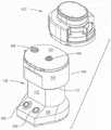
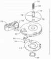
图1是本发明的骨清洁和碾磨组件的基部和清洁模块的透视图;Figure 1 is a perspective view of the base and cleaning module of the bone cleaning and grinding assembly of the present invention;

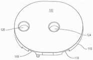
图2是如何将清洁模块可拆卸地附接到基部的透视图;Figure 2 is a perspective view of how the cleaning module is detachably attached to the base;

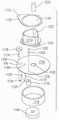
图3是如何将本发明的碾磨模块可拆卸地附接到基部的透视图;Figure 3 is a perspective view of how the milling module of the present invention is detachably attached to the base;

图4是组件的基部内部的剖视图;Figure 4 is a cross-sectional view of the interior of the base of the assembly;

图5是绘示图5A和5B如何布置在一起以形成本发明的基部内部部件的分解图的组装图;Figure 5 is an assembly view illustrating how Figures 5A and 5B are arranged together to form an exploded view of the base internal components of the present invention;

图6是基部的外壳顶板的顶表面的透视图;6 is a perspective view of the top surface of the housing top plate of the base;

图7是外壳顶板的底表面的透视图;Figure 7 is a perspective view of the bottom surface of the housing top plate;

图8是外壳内部的内板的透视图;Figure 8 is a perspective view of an inner panel inside the housing;

图9是马达和附接的主联接器的分解图,其中附接的主联接器是基部的一部分;Figure 9 is an exploded view of the motor and attached main coupling, which is part of the base;

图10是马达和主联接器的剖视图;Figure 10 is a sectional view of the motor and the main coupling;

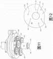
图11是环绕基部内部的主心轴设置的行星齿轮组件的透视图;Figure 11 is a perspective view of the planetary gear assembly disposed about the main spindle inside the base;

图12是基部内部的臂凸轮的平面图;Figure 12 is a plan view of the arm cam inside the base;

图13是基部内部的管凸轮的平面图;Figure 13 is a plan view of the tube cam inside the base;

图14是管凸轮的下侧的透视图;Figure 14 is a perspective view of the underside of the tube cam;

图15是示出平衡套环如何夹在臂凸轮和管凸轮之间的分解图;Figure 15 is an exploded view showing how the balance collar is sandwiched between the arm cam and the tube cam;

图16是离合器和管联接器如何设置在主心轴周围的透视图;Figure 16 is a perspective view of how the clutch and pipe coupler are arranged around the main spindle;

图17是离合器和管联接器的分解图;Figure 17 is an exploded view of the clutch and pipe coupling;

图18是离合器和管联接器的剖视图;Figure 18 is a sectional view of the clutch and pipe coupling;

图19是离合器输入环的顶部的透视图;Figure 19 is a perspective view of the top of the clutch input ring;

图20是离合器输入环的底侧的透视图;Figure 20 is a perspective view of the underside of the clutch input ring;

图21是离合器输出环的顶部的透视图;Figure 21 is a perspective view of the top of the clutch output ring;

图22是离合器输出环的顶部的第二透视图;Figure 22 is a second perspective view of the top of the clutch output ring;

图23是离合器保持架的顶部的透视图;Figure 23 is a perspective view of the top of the clutch cage;

图24是离合器保持架的底侧的透视图;Figure 24 is a perspective view of the underside of the clutch cage;

图25是离合器的沿着图18的线25-25截取的剖视图;25 is a cross-sectional view of the clutch taken along line 25-25 of FIG. 18;

图26是管联接器的透视图;Figure 26 is a perspective view of a pipe coupling;

图27是管联接器的剖视图;Figure 27 is a cross-sectional view of the pipe coupling;

图28是与离合器接合的棘爪的第一透视图;Figure 28 is a first perspective view of the pawl engaged with the clutch;

图29是棘爪和附接的部件的分解图;Figure 29 is an exploded view of the pawl and attached components;

图30绘示出棘爪与凸片的接合,其中凸片与离合器的内部联接器成一体;Figure 30 depicts the engagement of the pawl with the tab, where the tab is integral with the inner coupler of the clutch;

图31是与基部成一体的臂联接器以及绕臂联接器枢转的组件的第一透视图;Figure 31 is a first perspective view of the arm coupler integral with the base and the assembly pivoting about the arm coupler;

图32是与基部成一体的臂联接器以及绕臂联接器枢转的组件的第二透视图;Figure 32 is a second perspective view of the arm coupler integral with the base and the assembly pivoting about the arm coupler;

图33是与基部成一体的臂联接器以及绕臂联接器枢转的组件的剖视图;Figure 33 is a cross-sectional view of an arm coupler integral to the base and an assembly pivoting about the arm coupler;

图34是臂联接器以及绕臂联接器枢转的组件的分解图;Figure 34 is an exploded view of the arm coupler and components pivoting about the arm coupler;

图35是图31的枢转组件的轴的透视图;Figure 35 is a perspective view of the shaft of the pivot assembly of Figure 31;

图36是图30的枢转组件的帽盖的透视图;Figure 36 is a perspective view of the cap of the pivot assembly of Figure 30;

图37是帽盖的剖视图;Figure 37 is a sectional view of the cap;

图38是臂联接器的透视图;Figure 38 is a perspective view of an arm coupler;

图39是臂联接器的剖视图;Figure 39 is a cross-sectional view of the arm coupler;

图40是枢转组件的曲柄臂的透视图;Figure 40 is a perspective view of the crank arm of the pivot assembly;

图41是枢转组件的摇杆臂的透视图;Figure 41 is a perspective view of a rocker arm of a pivot assembly;

图42是附接到外壳的底侧的闩锁组件的透视图;Figure 42 is a perspective view of the latch assembly attached to the bottom side of the housing;

图43是闩锁组件的平面图;Figure 43 is a plan view of the latch assembly;

图44是致动本发明的组件的部件的框图;Figure 44 is a block diagram of the components that actuate the assembly of the present invention;

图45是清洁模块的透视图,绘示出如何将外壳可拆卸地附接到模块基部;Figure 45 is a perspective view of a cleaning module illustrating how the housing is detachably attached to the module base;

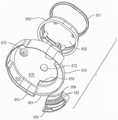
图46是清洁模块内部的部件的分解图;Figure 46 is an exploded view of the components inside the cleaning module;

图47是清洁模块顶部的内部部件的分解图;Figure 47 is an exploded view of the internal components of the top of the cleaning module;

图48是清洁模块和外壳以及位于外壳上方的部件的分解图;Figure 48 is an exploded view of the cleaning module and housing and components located above the housing;

图49是清洁模块的底板顶部的透视图;Figure 49 is a perspective view of the top of the floor of the cleaning module;

图50是清洁模块的底板底侧的透视图;Figure 50 is a perspective view of the underside of the floor of the cleaning module;

图51是带槽螺杆如何延伸穿过清洁模块外壳内部的盘的分解图;Figure 51 is an exploded view of how the slotted screw extends through the disc inside the cleaning module housing;

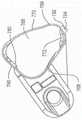
图52是清洁模块外壳内部的臂的俯视平面图;Figure 52 is a top plan view of an arm cleaning the interior of the module housing;

图53是臂的底侧的透视图;Figure 53 is a perspective view of the underside of the arm;

图54是臂的顶部的第一透视图;Figure 54 is a first perspective view of the top of the arm;

图55是臂的顶部的第二透视图;Figure 55 is a second perspective view of the top of the arm;

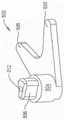
图56是清洁模块内部的驱动销顶部的透视图;Figure 56 is a perspective view of the top of the drive pin inside the cleaning module;

图57是驱动销的底表面的透视图;Figure 57 is a perspective view of the bottom surface of the drive pin;

图58是与清洁模块成一体的毂状件的第一透视图;Figure 58 is a first perspective view of a hub integral with a cleaning module;

图59是图58的毂状件的第二透视图;Figure 59 is a second perspective view of the hub of Figure 58;

图60是清洁模块内部的锁定板顶部的透视图;Figure 60 is a perspective view of the top of the locking plate inside the cleaning module;

图61是锁定板的底表面的透视图;Figure 61 is a perspective view of the bottom surface of the locking plate;

图62是本发明的组件的碾磨模块的分解图;Figure 62 is an exploded view of the milling module of the assembly of the present invention;

图63是碾磨模块的外壳顶部的透视图;Figure 63 is a perspective view of the top of the housing of the milling module;

图64是碾磨模块的外壳底侧的透视图;Figure 64 is a perspective view of the bottom side of the housing of the milling module;

图65是碾磨模块的顶板和料斗的顶部的透视图;Figure 65 is a perspective view of the roof of the milling module and the top of the hopper;

图66是碾磨模块的顶板和料斗的底侧的透视图;Figure 66 is a perspective view of the top deck of the milling module and the underside of the hopper;

图67是碾磨模块的碾磨盘和附接的联接心轴的透视图;67 is a perspective view of a milling disc and attached coupling mandrel of a milling module;

图68是碾磨模块的联接心轴的顶部的透视图;Figure 68 is a perspective view of the top of the coupling mandrel of the milling module;

图69是碾磨模块的联接心轴的底侧的透视图;Figure 69 is a perspective view of the underside of the coupling mandrel of the milling module;

图70是装配到碾磨模块的汇集托盘的顶部的透视图;Figure 70 is a perspective view of the top of the pool tray assembled to the milling module;

图71是汇集托盘的底侧的透视图;Figure 71 is a perspective view of the underside of the collection tray;

图72是安装到组件基部的清洁模块的剖视图;Figure 72 is a cross-sectional view of the cleaning module mounted to the base of the assembly;

图73绘示出在锁定板处于锁定状态时锁定板与驱动销的关系;Figure 73 depicts the relationship between the locking plate and the drive pin when the locking plate is in the locked state;

图74绘示出在锁定板处于非锁定状态时锁定板与清洁模块内部的驱动销的关系;Figure 74 depicts the relationship between the locking plate and the drive pin inside the cleaning module when the locking plate is in an unlocked state;

图75表示如何由于臂凸轮靠在摇杆臂上旋转而使摇杆臂变换经过清洁周期的各顺序阶段;Figure 75 shows how the rocker arm transitions through the sequential stages of the cleaning cycle as the arm cam rotates against the rocker arm;

图76表示如何由于离合器凸轮靠在棘爪上旋转而使棘爪变换经过清洁周期的各顺序阶段;Figure 76 shows how the pawl shifts through the sequential stages of the cleaning cycle as the clutch cam rotates against the pawl;

图77A至77E是在清洁周期的各阶段期间清洁模块的部件和设置在清洁模块中的骨料的示意图;77A to 77E are schematic illustrations of components of a cleaning module and aggregate disposed in the cleaning module during various stages of a cleaning cycle;

图78是安装到组件基部的碾磨模块的剖视图;Figure 78 is a cross-sectional view of a milling module mounted to the base of the assembly;

图79绘示出替代性清洁模块的保持架如何根据本发明设置在带槽螺杆和剃刮管周围;Figure 79 depicts how the cage of an alternative cleaning module is arranged around the slotted screw and shaving tube according to the present invention;

图80是图79的组件的分解图;Figure 80 is an exploded view of the assembly of Figure 79;

图81是图82的模块底侧的透视图;Figure 81 is a perspective view of the bottom side of the module of Figure 82;

图82是图79的模块的驱动组件的透视图;Figure 82 is a perspective view of the drive assembly of the module of Figure 79;

图83是替代性保持架的俯视平面图;Figure 83 is a top plan view of an alternative cage;

图84是保持架的底表面的透视图;Figure 84 is a perspective view of the bottom surface of the cage;

图85A至85G是示出保持架在相对于带槽螺杆和剃刮管的旋转以及环绕穿过保持架的纵向轴线的旋转中如何接合的一系列平面图;85A to 85G are a series of plan views showing how the cage engages in rotation relative to the grooved screw and shaving tube and about a longitudinal axis through the cage;

图86是本发明的替代性清洁模块的内侧的透视图;Figure 86 is a perspective view of the inside of an alternative cleaning module of the present invention;

图87是在图86的清洁模块内部的替代性剃刮管的透视图;并且Figure 87 is a perspective view of an alternative shaving tube inside the cleaning module of Figure 86; and

图88是在本发明的清洁模块的汇集区内部的替代性毂状件的透视图。88 is a perspective view of an alternative hub inside the collection area of the cleaning module of the present invention.

具体实施方式detailed description

I.概述I. Overview

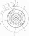
图1-3示出了本发明的骨清洁和碾磨系统100的基本部件。系统100包括基部102,其中骨清洁模块602可拆卸地附接到基部。骨清洁模块602接收获取的骨料。一旦致动基部102,在附接清洁模块602时,清洁模块602内部的部件协作以移除附接到骨料的软组织。如图3中可见,第二模块是碾磨模块902,其也是系统100的一部分且可拆卸地附接到基部102。在骨料被清洁之后,从基部102移除清洁模块602并将碾磨模块902附接到基部。经过清洁的骨料被从清洁模块602传送到碾磨模块902。再次致动组件的基部102。这导致碾磨模块902内部的部件将经过清洁的骨料转换成较小尺寸的骨碎片。骨碎片可用作外科手术中的填料。1-3 illustrate the basic components of a bone cleaning and grindingsystem 100 of the present invention.System 100 includesbase 102 withbone cleaning module 602 removably attached to the base. Thebone cleaning module 602 receives harvested aggregate. Once thebase 102 is actuated, when thecleaning module 602 is attached, components inside thecleaning module 602 cooperate to remove soft tissue attached to the aggregate. As can be seen in FIG. 3 , the second module is amilling module 902 which is also part of thesystem 100 and is detachably attached to thebase 102 . After the aggregate is cleaned, thecleaning module 602 is removed from thebase 102 and themilling module 902 is attached to the base. Cleaned aggregate is conveyed from cleaningmodule 602 to millingmodule 902 . Thebase 102 of the assembly is actuated again. This causes components inside themilling module 902 to convert the cleaned aggregate into smaller sized bone fragments. Bone fragments can be used as filler in surgical procedures.

基部102内部有马达140(图4)。在模块602或902连接到基部102时,该模块内部的多个移动部件连接到马达140。通过按压基部102上的开关588或590,致动马达140。马达140的致动导致模块602或902(分别对骨进行清洁或碾磨)内部的部件产生类似的致动。Inside thebase 102 is a motor 140 (FIG. 4). When themodule 602 or 902 is connected to thebase 102 , the various moving parts inside the module are connected to themotor 140 . By pressing aswitch 588 or 590 on thebase 102, themotor 140 is actuated. Actuation ofmotor 140 results in similar actuation of components insidemodules 602 or 902 (cleaning or grinding bone, respectively).

II.组件的基部II. The base of the assembly

如参照图2和3所示,组件的基部102包括外壳104,这是基部的外部主体。外壳104形成有底座106,该底座从重力基准平面来说是外壳的最底部的部分。颈部112从底座106向上延伸。在平行于重力基准平面的剖面中,颈部112的面积小于底座106。颈部112的周边位于底座的外周边的内部。外壳104被进一步形成为使得底座106具有面板108,该面板从底座的最宽部分向内渐缩且被成形为具有到达颈部112的面板108。As shown with reference to Figures 2 and 3, thebase 102 of the assembly includes ahousing 104, which is the outer body of the base. Thehousing 104 is formed with abase 106, which is the bottommost portion of the housing from a gravitational reference plane.Neck 112 extends upwardly frombase 106 . In a section parallel to the gravitational reference plane, theneck 112 has a smaller area than thebase 106 . The perimeter of theneck 112 is inward of the outer perimeter of the base. Thehousing 104 is further formed such that thebase 106 has apanel 108 that tapers inwardly from the widest portion of the base and is shaped to have thepanel 108 reach theneck 112 .

在颈部112上方,外壳104被成形为具有头部114。外壳104被成形为使得头部114从颈部112向外突出。在本发明的所示型式中,颈部112和头部114两者在剖面上呈现为截顶椭圆的形状。(颈部和头部的弯曲的侧面部分分别对着(subtend)小于180°的弧。顶板122是头部114和(延伸而言)外壳104的最顶部的结构面板。顶板122从头部114的毗邻的外周边向内凹陷大约5mm。顶板122具有环绕板122的平坦顶表面沿周向且从板122的平坦顶表面向下延伸的边沿116。从头部114的外表面向内延伸到边沿的台阶部115用作头部114的外周边与顶板的边沿115之间的过渡表面。Above theneck 112 , thehousing 104 is shaped with ahead 114 . Thehousing 104 is shaped such that ahead 114 protrudes outwardly from theneck 112 . In the version of the invention shown, both theneck 112 and thehead 114 assume the shape of a truncated ellipse in cross-section. (The curved side portions of the neck and head each subtend an arc of less than 180°. Thetop plate 122 is the topmost structural panel of thehead 114 and (by extension) theshell 104. Thetop plate 122 extends from thehead 114 The adjacent outer periphery of the inward depression about 5mm.Top plate 122 has the flat top surface ofplate 122 along the circumferential direction and theedge 116 that extends downward from the flat top surface ofplate 122. Extends inwardly to edge from the outer surface ofhead 114 The steppedportion 115 serves as a transition surface between the outer periphery of thehead 114 and therim 115 of the top plate.

顶板122被进一步形成为使得边沿116中存在四个矩形开口118,开口在图6和7中标示出。开口118被设置在边沿116的毗邻顶板122的前边缘和后边缘的区段中。顶板的前边缘应理解为外壳基部的面板108上方的边缘。后边缘是最远离基部的面板108的边缘。Thetop plate 122 is further formed such that there are fourrectangular openings 118 in therim 116 , the openings being labeled in FIGS. 6 and 7 .Openings 118 are provided in sections ofrim 116 adjacent the front and rear edges oftop panel 122 . The front edge of the top panel is understood to be the edge above thepanel 108 of the base of the housing. The rear edge is the edge of thepanel 108 furthest from the base.

顶板122还具有两个开口,开口124和126。开口124和126两者在横跨板122从一侧到另一侧延伸的主轴线上居中。开口124与横跨板的短轴线间隔开大约1cm。短轴线是从面板前边缘的中点延伸到面板后边缘的中点的轴线。开口126被设置在板的短轴线的与最接近于开口124的一侧相反的一侧上。开口126被与短轴线相比更接近顶板122的毗邻的弯曲侧面定位。边沿116也被成形以限定仅在图43中标示出的槽119。槽119延伸穿过边沿116的毗邻开口126设置的弯曲侧面。Top plate 122 also has two openings,openings 124 and 126 . Bothopenings 124 and 126 are centered on the main axis extending acrossplate 122 from side to side. Theopenings 124 are spaced about 1 cm apart from the minor axis of the transverse plate. The minor axis is the axis extending from the midpoint of the front edge of the panel to the midpoint of the rear edge of the panel. Theopening 126 is provided on the opposite side of the minor axis of the plate from the side closest to theopening 124 . Theopening 126 is positioned closer to the adjacent curved side of thetop plate 122 than to the minor axis. Therim 116 is also shaped to define aslot 119 only indicated in FIG. 43 .Slot 119 extends through a curved side ofrim 116 disposedadjacent opening 126 .

顶板122还被形成为具有套筒123、127和128,其从板122的平面部分的底表面向下突出。套筒123从板的位于开口124下方的平面部分向下延伸。套筒127和128是同心的,且从板的位于开口126下方的平面部分向下延伸。套筒127是最内部的套筒,即限定了从开口126向内延伸的膛孔(膛孔在图中未标示出)的套筒。套筒128是最外部的套筒,且与套筒127径向向外地间隔开。顶板122被进一步形成为使得与套筒127相比,套筒128从顶板122向下突出。还看到,多个立柱129从顶板122的底表面向下突出,图中标示出两个立柱。立柱的自由端被示为具有膛孔(膛孔在图中未标示出)。膛孔的存在是为了容纳如下文所述的紧固件。Thetop plate 122 is also formed withsleeves 123 , 127 and 128 protruding downward from the bottom surface of the planar portion of theplate 122 . Asleeve 123 extends downwardly from a planar portion of the plate below theopening 124 .Sleeves 127 and 128 are concentric and extend downward from the planar portion of the plate belowopening 126 .Sleeve 127 is the innermost sleeve, ie, the sleeve defining a bore (bore not shown) extending inwardly from opening 126 .Sleeve 128 is the outermost sleeve and is spaced radially outwardly fromsleeve 127 . Thetop plate 122 is further formed such that asleeve 128 protrudes downward from thetop plate 122 compared with thesleeve 127 . It is also seen that a plurality ofuprights 129 protrude downwardly from the bottom surface of thetop plate 122, two uprights being indicated in the figure. The free ends of the posts are shown with bores (the bores are not labeled in the figure). Bores exist to accommodate fasteners as described below.

两个支撑构件静态地安装到外壳104内侧。支撑构件中的第一个是仅在图4可见的马达安装座132。马达安装座132的形状是大体板状的,且安装在颈部112中以便相对接近底座106。马达安装座132被形成有大的通孔134。Two support members are statically mounted to the inside of thehousing 104 . The first of the support members is themotor mount 132 visible only in FIG. 4 . Themotor mount 132 is generally plate-like in shape and is mounted in theneck 112 so as to be relatively close to thebase 106 . Themotor mount 132 is formed with a large throughhole 134 .

第二支撑构件,即内板150,被设置在外壳的头部114中。图中并未标示出外壳内部的台阶部,其中内板150的外周边座置在该台阶部上。如图8中最佳可见,板150具有平坦的基部152。板150被进一步形成为具有两个空隙,空隙156和162,其从基部152中的开口向下延伸。内板150被成形为使得空隙156大致呈具有修圆的顶点的三角形形状。内板150被形成为使得空隙156位于顶板的开口126下方。空隙156的基部由位于基部152下方的面板160限定。从基部向下延伸以将面板连接到基部的腹板158限定了空隙156的周边。空隙162被定位成与顶板的开口124共轴。位于板的基部152下方的凸台(boss)166限定了空隙162的基部。腹板164是板150的一部分,其从板的基部152延伸到凸台166,将凸台保持到板150的其余部分,且还限定了空隙162的外周边。The second support member, theinner plate 150, is disposed in thehead 114 of the housing. The figure does not show the stepped portion inside the housing, wherein the outer periphery of theinner plate 150 is seated on the stepped portion. As best seen in FIG. 8 , theplate 150 has aflat base 152 .Plate 150 is further formed with two voids, voids 156 and 162 , extending downwardly from openings inbase 152 . Theinner panel 150 is shaped such that thevoid 156 is generally triangular in shape with rounded vertices. Theinner panel 150 is formed such that avoid 156 is located below theopening 126 of the top panel. The base of the void 156 is defined by apanel 160 located below thebase 152 . Aweb 158 extending downwardly from the base to connect the panels to the base defines the perimeter of thevoid 156 . Thevoid 162 is positioned coaxially with theopening 124 of the top plate. Aboss 166 located below thebase 152 of the plate defines the base of thevoid 162 .Web 164 is the portion ofplate 150 that extends frombase 152 of the plate toboss 166 , holds the boss to the remainder ofplate 150 , and also defines the outer perimeter ofvoid 162 .

马达安装座132和内板150均可视为具有多个开口、贯通膛孔和闭端膛孔。开口和膛孔中的一些由沉孔环绕。这些膛孔中的一些从圆形岛状部向下开口,圆形岛状部从马达安装座132和板的基部152的顶部指向表面向上延伸。这些开口、膛孔、沉孔和岛状部在图中并未标示出。应当理解,这些膛孔和沉孔接收将组件的基部102的下述部件保持到马达安装座132和内板150的销和紧固件。内板150中的开口中的一些被定位成与从顶板122向下延伸的立柱129对准。延伸穿过内板150中的开口且进入到立柱129中的毗邻的膛孔中的紧固件(未示出)将内板保持到立柱129。立柱129因此将内板150连接到顶板122,使得包括安装到板122和150的部件的这一子组件可作为单个单元装配到外壳104中。Both themotor mount 132 and theinner plate 150 can be considered to have a plurality of openings, through bores and closed end bores. Some of the openings and bores are surrounded by counterbores. Some of these bores open downward from circular islands extending upward from the top facing surface of themotor mount 132 andbase 152 of the plate. These openings, bores, counterbores and islands are not shown in the figures. It should be understood that these bores and counterbores receive pins and fasteners that hold the following components of thebase 102 of the assembly to themotor mount 132 andinner plate 150 . Some of the openings in theinner panel 150 are positioned to align with theposts 129 extending downward from thetop panel 122 . Fasteners (not shown) extending through openings ininner panel 150 and into adjacent bores inpost 129 retain the inner panel to post 129 .Uprights 129 thus connectinner panel 150 totop panel 122 so that this subassembly, including components mounted topanels 122 and 150, can fit intoouter shell 104 as a single unit.

马达140被安装到马达安装座132的向下指向表面。紧固件(未示出)将马达140保持到安装座132。马达140具有延伸穿过贯穿安装座132的开口的轴142,该轴仅在图10中以剖面的方式可见。轴142延伸穿过的开口的直径大于轴的直径。马达140被安装在外壳102中,使得马达的轴与外壳的顶板122中的开口124共轴。Amotor 140 is mounted to a downwardly pointing surface of themotor mount 132 . Fasteners (not shown)hold motor 140 to mount 132 . Themotor 140 has ashaft 142 extending through an opening through themount 132 , which shaft is only visible in section in FIG. 10 . The diameter of the opening through which theshaft 142 extends is larger than the diameter of the shaft. Themotor 140 is mounted in thehousing 102 such that the shaft of the motor is coaxial with theopening 124 in thetop plate 122 of the housing.

马达轴142连接到传动机构144,该传动机构的外壳在图中可见。传动机构144被座置在马达安装座132内部的开口134中,以便设置在马达140的紧邻开口134下方设置的部分的上方。传动机构144通常包括行星齿轮组件,该行星齿轮组件使马达的轴142的旋转运动的速度逐渐减小。传动机构的旋转运动通过轴145输出,该轴从传动机构的外壳向上延伸。在本发明的一个型式中,马达140被设计成使得在被致动时,其以马达轴142的介于2500到5500RPM之间的速度旋转。传动机构144被配置成使得马达的轴142与传动机构的轴145之间的速度比介于5:1和90:1之间。Themotor shaft 142 is connected to atransmission 144, the housing of which is visible in the figure. Thetransmission mechanism 144 is seated in theopening 134 inside themotor mount 132 so as to be disposed above the portion of themotor 140 disposed immediately below theopening 134 . Thetransmission 144 generally includes a planetary gear assembly that tapers the speed of the rotational motion of themotor shaft 142 . Rotary motion of the transmission is output throughshaft 145 which extends upwardly from the housing of the transmission. In one version of the invention, themotor 140 is designed such that when actuated, it rotates at a speed of between 2500 and 5500 RPM of themotor shaft 142 . Thetransmission 144 is configured such that the speed ratio between theshaft 142 of the motor and theshaft 145 of the transmission is between 5:1 and 90:1.

传动机构144的基部直接附接到马达140的壳体的表面。传动机构144的基部因此座置在马达安装座132中的开口中,其中马达轴142延伸穿过该开口。传动机构144的顶表面被安装到凸台166的与板152成一体的下表面。在本发明的所示型式中,板151被设置在传动机构144的顶部与凸台166的底侧之间。板151可由弹性体材料形成以缓冲马达的振动。延伸穿过板151进入到传动机构顶部中的紧固件147(在图4中标示出一个紧固件)将板保持到传动机构。传动机构144具有轴145,该轴延伸穿过凸台166中的开口以便延伸到板150内部的空隙162中。传动机构的轴145通常是圆柱形形状。图9中标示出的键146从轴145的圆柱形表面向外延伸。键146沿着轴145纵向地延伸。The base of thetransmission mechanism 144 is attached directly to the surface of the housing of themotor 140 . The base of thetransmission mechanism 144 is thus seated in the opening in themotor mount 132 through which themotor shaft 142 extends. The top surface of thetransmission mechanism 144 is mounted to the lower surface of theboss 166 integral with theplate 152 . In the version of the invention shown,plate 151 is disposed between the top oftransmission 144 and the bottom side ofboss 166 . Theplate 151 may be formed of an elastomer material to damp vibration of the motor. Fasteners 147 (one fastener is labeled in FIG. 4 ) extending through theplate 151 into the top of the transmission retain the plate to the transmission. Thetransmission mechanism 144 has ashaft 145 that extends through an opening in aboss 166 to extend into thevoid 162 inside theplate 150 . Theshaft 145 of the transmission mechanism is generally cylindrical in shape. Extending outwardly from the cylindrical surface ofshaft 145 is a key 146 labeled in FIG. 9 .Key 146 extends longitudinally alongshaft 145 .

在图9和10中最佳可见的心轴170被安装到传动机构的轴145以便与轴145一致地旋转。心轴170包括圆柱形的基部172。圆柱形的主干176从基部172向上延伸。主干176与基部172共轴,且具有小于基部直径的直径。在毗邻主干从基部172露出的位置,心轴170被成形为具有环绕主干延伸的台阶部174。在主干176上方,心轴具有颈部180。颈部180与主干176共轴,且其直径小于主干的直径。第二台阶部178因此从颈部180的底部径向向外地沿周向延伸,以便起到主干176与颈部180之间的过渡表面的作用。心轴的最顶部部分是头部182。头部182与心轴的颈部180共轴,且具有小于心轴的颈部的直径的直径。Thespindle 170 , best seen in FIGS. 9 and 10 , is mounted to theshaft 145 of the transmission so as to rotate in unison with theshaft 145 . Themandrel 170 includes acylindrical base 172 . Acylindrical stem 176 extends upwardly from thebase 172 . Thestem 176 is coaxial with thebase 172 and has a smaller diameter than the base. Where adjacent the trunk emerges from thebase 172, themandrel 170 is shaped with astep 174 extending around the trunk. Above thestem 176 the mandrel has aneck 180 .Neck 180 is coaxial withstem 176 and has a smaller diameter than the stem. Thesecond step 178 thus extends circumferentially radially outward from the bottom of theneck 180 so as to function as a transition surface between thestem 176 and theneck 180 . The topmost portion of the mandrel is thehead 182 . Thehead 182 is coaxial with theneck 180 of the mandrel and has a diameter smaller than the diameter of the neck of the mandrel.

心轴170被进一步形成为具有从基部172的底部向上延伸的闭端膛孔184。膛孔184与基部172共轴。凹陷186从心轴的颈部180的外表面向内延伸。心轴170被进一步形成为使得膛孔188穿过心轴的头部182纵向延伸。在本发明的所示型式中,膛孔188在垂直于中心径向线的轴线上居中,该中心径向线向内延伸穿过凹陷186到达心轴170的纵向轴线。Themandrel 170 is further formed with a closed-endedbore 184 extending upwardly from the bottom of thebase 172 .Bore 184 is coaxial withbase 172 . Arecess 186 extends inwardly from the outer surface of theneck 180 of the mandrel. Themandrel 170 is further formed such that abore 188 extends longitudinally through thehead 182 of the mandrel. In the illustrated version of the invention, thebore 188 is centered on an axis perpendicular to a central radial line extending inwardly through therecess 186 to the longitudinal axis of themandrel 170 .

心轴170被座置在传动机构144上,使得传动机构的轴145座置在心轴的膛孔184中。键146座置在心轴内部的槽185中,该槽从膛孔184的外周边向外延伸。这种键在槽中的布置结构确保了传动机构的轴145和心轴170作为单个单元旋转。Thespindle 170 is seated on thetransmission 144 such that theshaft 145 of the transmission is seated in thebore 184 of the spindle. The key 146 is seated in aslot 185 inside the mandrel that extends outwardly from the outer periphery of thebore 184 . This key-in-slot arrangement ensures that thetransmission shaft 145 andspindle 170 rotate as a single unit.

齿轮190被设置于心轴的主干176周围,以与心轴170一致地旋转。齿轮170座置在台阶部174上。齿轮190的齿被设置在心轴的基部172上方且从台阶部174径向向外的位置(齿轮的齿未示出)。Agear 190 is disposed about thestem 176 of the mandrel to rotate in unison with themandrel 170 . Thegear 170 is seated on the steppedportion 174 . The teeth of thegear 190 are provided at a location above thebase 172 of the spindle and radially outward from the step 174 (the teeth of the gear are not shown).

主联接器194被安装到心轴170。主联接器194包括圆柱形的基部196。销198从基部196的顶部向上延伸。三个等角度间隔开的齿202也被设置于基部196的顶部上。每个齿202是一个细长构件,其从销198径向向外突出且从基部196的顶部向上延伸。主联接器194被形成为使得销198在齿202上方突出。Main coupler 194 is mounted tospindle 170 . Themain coupler 194 includes acylindrical base 196 . Apin 198 extends upwardly from the top of thebase 196 . Three equally angularly spacedteeth 202 are also provided on top of thebase 196 . Eachtooth 202 is an elongated member that projects radially outward from thepin 198 and extends upwardly from the top of thebase 196 . Themain coupler 194 is formed such that thepin 198 protrudes above theteeth 202 .

主联接器194被进一步形成为具有从基部196的底部向上延伸的膛孔204。膛孔204具有允许心轴的头部182紧密地滑动配合在膛孔204中的直径。膛孔204通向闭端膛孔206,该闭端膛孔朝向基部196的顶部延伸。主联接器194被形成为使得膛孔206的直径小于膛孔204的直径。更具体地讲,联接器194被形成为使得膛孔206的直径小于杆170的头部182的直径。联接器194被进一步形成为具有两个沿直径相对的椭圆形开口208,其从基部196的圆柱形外表面向内延伸(图10中可见一个开口208)。开口208延伸到膛孔204中。Themain coupler 194 is further formed with abore 204 extending upwardly from the bottom of thebase 196 . Thebore 204 has a diameter that allows thehead 182 of the mandrel to fit snugly in thebore 204 . Bore 204 leads to a closed-end bore 206 that extends toward the top ofbase 196 . Themain coupler 194 is formed such that the diameter of thebore 206 is smaller than the diameter of thebore 204 . More specifically, thecoupler 194 is formed such that the diameter of thebore 206 is smaller than the diameter of thehead 182 of therod 170 . Thecoupler 194 is further formed with two diametrically opposedoval openings 208 extending inwardly from the cylindrical outer surface of the base 196 (oneopening 208 is visible in FIG. 10 ).Opening 208 extends intobore 204 .

主联接器194被装配到组件的基部102的其余部分,使得心轴的头部182被设置于联接器的膛孔204中。销210延伸穿过联接器的开口208,且进入到心轴的头部182内部的膛孔188中。销210将主联接器194保持到心轴170,使得联接器与心轴一致地旋转,且能够沿着穿过心轴的纵向轴线纵向移动。主联接器被定位成使得联接器的基部196的顶部延伸穿过顶板的开口124。联接器的销198和齿202被设置在外壳顶板122上方。Themain coupler 194 is fitted to the remainder of thebase 102 of the assembly such that thehead 182 of the mandrel is disposed in thebore 204 of the coupler. Thepin 210 extends through thecoupling opening 208 and into thebore 188 inside thehead 182 of the mandrel.Pin 210 holdsmain coupler 194 to mandrel 170 such that the coupler rotates in unison with the mandrel and is movable longitudinally along a longitudinal axis passing through the mandrel. The main coupler is positioned such that the top of thebase 196 of the coupler extends through theopening 124 of the top plate. Thepins 198 andteeth 202 of the coupler are disposed above thehousing top plate 122 .

图5A中可见的弹簧212被设置于联接器的膛孔208中。弹簧212提供通常使联接器移位的偏压力,使得联接器的销198和齿202与外壳的顶板122间隔开。联接器194的向上移动受联接器的限定开口208的邻接销210的底部的部分的限制。联接器的向下移动受联接器内部的台阶部的限制,该台阶部限定从膛孔204到邻接心轴的头部182的顶部的膛孔208的过渡。Aspring 212, visible in Figure 5A, is disposed in thebore 208 of the coupler.Spring 212 provides a biasing force that generally displaces the coupler so thatpin 198 andteeth 202 of the coupler are spaced fromtop plate 122 of the housing. Upward movement of thecoupler 194 is limited by the portion of the coupler that defines theopening 208 abutting the bottom of thepin 210 . Downward movement of the coupler is limited by a step inside the coupler that defines the transition frombore 204 to bore 208 adjoining the top of the mandrel'shead 182 .

次传动机构220(其部件在图5A、5B和11中最佳可见)被设置在心轴170的颈部180周围。次传动机构220包括设置于内板150内部的空隙162中的环形齿轮222。齿轮222被定位成使得齿轮的外表面抵靠在腹板164的内表面上。环形齿轮的齿(齿在图中未标示出)朝向空隙162的中心向内延伸。设置于环形齿轮222的外周边周围和上方的卡扣环在图中未示出。该卡扣环从腹板164中的沟槽向外突出。卡扣环将环形齿轮222保持在空隙162中。A secondary transmission 220 (components of which are best seen in FIGS. 5A , 5B and 11 ) is disposed about theneck 180 of thespindle 170 . Thesecondary transmission 220 includes aring gear 222 disposed within thevoid 162 inside theinner plate 150 .Gear 222 is positioned such that the outer surface of the gear abuts against the inner surface ofweb 164 . Teeth of the ring gear (teeth not shown) extend inwardly towards the center of thevoid 162 . The snap rings provided around and over the outer periphery of thering gear 222 are not shown in the drawings. The snap ring protrudes outwardly from a groove in theweb 164 . The snap ring retainsring gear 222 invoid 162 .

传动机构220还包括第一组行星齿轮,齿轮224。齿轮224通过销225可旋转地安装到承载架226。齿轮224与齿轮190和环形齿轮222的齿啮合。承载架226自身具有太阳齿轮228,该太阳齿轮环绕心轴170的颈部176。太阳齿轮228的内径与心轴170径向向外地间隔开。Transmission mechanism 220 also includes a first set of planetary gears,gear 224 .Gear 224 is rotatably mounted tocarrier frame 226 bypin 225 .Gear 224 meshes with the teeth ofgear 190 andring gear 222 . Thecarrier 226 itself has asun gear 228 which surrounds theneck 176 of thespindle 170 . The inner diameter of thesun gear 228 is spaced radially outward from thespindle 170 .

三个行星齿轮230(也是次传动机构220的一部分)在环形齿轮222和太阳齿轮228之间延伸。行星齿轮230通过销231可旋转地安装到下述的臂凸轮234。次传动机构被设计成使得臂凸轮和附接的部件以小于心轴的旋转速度的速度旋转。在本发明的一些型式中,心轴170与臂凸轮234之间的速度比介于12:1和24:1之间。Three planetary gears 230 (also part of secondary transmission 220 ) extend betweenring gear 222 andsun gear 228 . Theplanetary gear 230 is rotatably mounted to anarm cam 234 described below through apin 231 . The secondary drive mechanism is designed such that the arm cam and attached components rotate at a speed less than the rotational speed of the spindle. In some versions of the invention, the speed ratio between thespindle 170 and thearm cam 234 is between 12:1 and 24:1.

在图12中最佳可见的臂凸轮234是大体盘形的部件。臂凸轮234被形成有中心开口236。开口236被设定尺寸以便具有大于心轴的颈部182的直径的直径。臂凸轮具有两个凸部。外凸部,凸部238,具有与凸轮234的中心相对远地间隔开的外周边。外凸部238对着环绕凸轮234的外侧延伸超过180°的弧。在本发明的一些型式中,外凸部对着介于190°和240°之间的弧。第二凸部是内凸部242。内凸部242具有与外凸部238的外周边径向向内地间隔开的外周边。内凸部232对着环绕凸轮234介于20°和60°之间的角。外凸部238的每一端与内凸部242的毗邻端之间的过渡表面在图中未标示出。Thearm cam 234, best seen in FIG. 12, is a generally disc-shaped member. Thearm cam 234 is formed with acentral opening 236 . Theopening 236 is sized to have a diameter greater than the diameter of theneck 182 of the mandrel. The arm cam has two protrusions. The outer protrusion,boss 238 , has an outer perimeter spaced relatively far from the center ofcam 234 .Outer protrusion 238 extends over an arc of more than 180° towards the outside of encirclingcam 234 . In some versions of the invention, the bulge subtends an arc of between 190° and 240°. The second convex portion is the innerconvex portion 242 . The innerconvex portion 242 has an outer periphery spaced radially inwardly from the outer periphery of the outerconvex portion 238 . The inner convex portion 232 subtends the surroundingcam 234 at an angle between 20° and 60°. The transition surfaces between each end of theouter protrusion 238 and the adjacent end of theinner protrusion 242 are not shown in the figures.

臂凸轮234被形成有两组贯通膛孔,其从一侧到另一侧延伸穿过凸轮,且与开口236径向向外地间隔开。第一组膛孔是三个等角度间隔开的膛孔244。膛孔244接收将行星齿轮230可旋转地保持到臂凸轮的销231。第二组膛孔是三个等角度间隔开的膛孔245。膛孔245的直径大于膛孔244,与膛孔244成角度地偏置,且与膛孔244稍微径向向外地间隔开。膛孔245接收将下述的管凸轮252保持到臂凸轮234的紧固销(紧固销未示出)。Arm cam 234 is formed with two sets of through bores extending through the cam from side to side and spaced radially outwardly fromopening 236 . The first set of bores is three equally angularly spaced bores 244 . Thebore 244 receives thepin 231 that rotatably holds theplanet gear 230 to the arm cam. The second set of bores is three equally angularly spaced bores 245 .Bore 245 has a larger diameter thanbore 244 , is angularly offset frombore 244 , and is spaced slightly radially outward frombore 244 .Bore 245 receives a fastening pin (fastening pin not shown) that holdstube cam 252 , described below, toarm cam 234 .

现在参照图13和14描述的管凸轮252被安装到臂凸轮234。管凸轮252是包括环形裙边254的单件式部件。边沿256被设置于裙边254上方且从裙边径向向外地延伸。管凸轮252被形成为使得边沿256相应地具有内凸部258和外凸部262。内凸部258具有外表面260,就径向距离而言该外表面被相对接近凸轮的中心定位。内凸部258对着环绕凸轮252大于180°的弧。在本发明的一些型式中,内凸部258对着介于185°和205°之间的弧。外凸部262被成形为具有外表面264,该外表面被与内凸部252的表面260相比更远离凸轮252的中心轴线定位。管凸轮252被形成为使得凸轮表面264对着环绕凸轮中心介于40°与140°之间的弧。外表面260和外表面264之间的过渡表面在图中未标示出。Thetube cam 252 described with reference to FIGS. 13 and 14 is mounted to thearm cam 234 .Tube cam 252 is a one-piece component includingannular skirt 254 . Arim 256 is disposed above theskirt 254 and extends radially outward from the skirt.Tube cam 252 is formed such thatrim 256 has aninner protrusion 258 and anouter protrusion 262 , respectively. Theinner protrusion 258 has anouter surface 260 that is located relatively close to the center of the cam in terms of radial distance. Theinner protrusion 258 subtends an arc of greater than 180° around thecam 252 . In some versions of the invention, theinner protrusion 258 subtends an arc of between 185° and 205°. Theouter boss 262 is shaped to have anouter surface 264 that is positioned farther from the central axis of thecam 252 than thesurface 260 of theinner boss 252 .Tube cam 252 is formed such thatcam surface 264 subtends an arc of between 40° and 140° around the center of the cam. The transition surface betweenouter surface 260 andouter surface 264 is not shown in the drawings.

管凸轮252被形成为使得裙边254和边沿262共同限定延伸穿过凸轮中心的开口266。管凸轮被进一步形成为限定突出到开口266中且环绕开口266沿周向延伸的台阶部268。台阶部268被设置在边沿262的顶表面下方。图14中标示出的三个等角度间隔开的膛孔270从裙边254的底部延伸到台阶部268的顶部。在基部102组装之后,管凸轮的膛孔270与臂凸轮的膛孔245配准。膛孔270接收将剃刮凸轮252保持到臂凸轮234的紧固销。Tube cam 252 is formed such thatskirt 254 andrim 262 together define anopening 266 extending through the center of the cam. The tube cam is further formed to define astep 268 that protrudes into theopening 266 and extends circumferentially around theopening 266 . A steppedportion 268 is provided below the top surface of therim 262 . Three equiangularly spaced bores 270 labeled in FIG. 14 extend from the bottom ofskirt 254 to the top of steppedportion 268 . After thebase 102 is assembled, the tube cam bore 270 registers with the arm cam bore 245 .Bore 270 receives a securing pin that retains shavingcam 252 toarm cam 234 .

如图15中最佳可见,平衡套圈246被夹在臂凸轮234与管凸轮252之间。平衡套圈246包括中心环247。组件102被构造成使得裙边254被设置在由环247限定的空隙中并在其中旋转。四个凸片(图15中可见两个)从中心环247向外突出。紧固件249(图中标示出三个紧固件)延伸穿过凸片248中的每一个。紧固件249被固定到内板150的基部152。紧固件249因此将平衡套圈246静态地保持到组件基部102。凸片248和紧固件249被设置在相对于臂凸轮234径向向外的位置。因此,静态的平衡套圈246的存在不会阻碍臂凸轮234和管凸轮252的旋转。As best seen in FIG. 15 ,balance collar 246 is sandwiched betweenarm cam 234 andtube cam 252 . Thebalance collar 246 includes acenter ring 247 .Assembly 102 is configured such thatskirt 254 is disposed within and rotates within the void defined byring 247 . Four tabs (two visible in FIG. 15 ) project outwardly from thecenter ring 247 . Fasteners 249 (three fasteners are labeled) extend through each of thetabs 248 .Fasteners 249 are secured to thebase 152 of theinner panel 150 .Fastener 249 thus statically holdsbalance collar 246 toassembly base 102 .Tab 248 andfastener 249 are disposed in a radially outward position relative toarm cam 234 . Thus, the presence of thestatic balance collar 246 does not impede the rotation of thearm cam 234 andtube cam 252 .

图16-18中最佳可见的离合器组件278环绕心轴170设置于管凸轮252上方。在图16和18中,臂凸轮234、剃刮凸轮252和臂凸轮234下方的齿轮组件不可见,以简化附图。Clutch assembly 278 , best seen in FIGS. 16-18 , is disposed abovetube cam 252 aroundspindle 170 . In Figures 16 and 18, thearm cam 234, theshaving cam 252, and the gear assembly below thearm cam 234 are not visible to simplify the drawings.

离合器组件278包括输入环280。图19和20中最佳可见的输入环280具有管状形状的杆282。杆282被形成有贯通膛孔284,且被确定尺寸以紧密配合在心轴的颈部180周围。槽285从杆282的限定膛孔284的内表面向外延伸。槽285因此与膛孔284相连。输入环280被进一步形成为具有从杆282的顶部径向向外地延伸的头部286。头部286被示为具有从头部的外表面向外突出的环(图中未标示出)。该环为输入环280提供了机械强度。头部286被形成为在头部的中心处限定圆形空隙288。空隙288与延伸穿过杆282的膛孔284相连,且其直径大于膛孔284。头部286被进一步形成为使得具有环绕膛孔284中的开口的凹面290。Clutch assembly 278 includes aninput ring 280 . Theinput ring 280 , best seen in FIGS. 19 and 20 , has arod 282 in the shape of a tube. Therod 282 is formed with a throughbore 284 and is sized to fit snugly around theneck 180 of the mandrel. Aslot 285 extends outwardly from an inner surface of therod 282 that defines thebore 284 . Thegroove 285 is thus connected to thebore 284 . Theinput ring 280 is further formed with ahead 286 extending radially outward from the top of therod 282 . Thehead 286 is shown as having a ring (not labeled) protruding outwardly from the outer surface of the head. This ring provides mechanical strength toinput ring 280 . Thehead 286 is formed to define acircular void 288 at the center of the head. Thevoid 288 is connected to thebore 284 extending through therod 282 and has a larger diameter than thebore 284 . Thehead 286 is further formed so as to have aconcave surface 290 surrounding the opening in thebore 284 .

输入环280被装配到心轴270以使得环的杆284被设置于心轴的颈部180上。杆284被设置于臂凸轮234的开口236内。环的头部286的下部部分被设置于管凸轮的开口266内。仅在图18中标示出的键181从心轴的颈部180向外延伸。键181座置在输入环280内部的槽285中。这种键在槽中的布置结构确保了心轴170和离合器输出环作为单件式单元旋转。Theinput ring 280 is fitted to themandrel 270 such that therod 284 of the ring is disposed on theneck 180 of the mandrel. Therod 284 is disposed within theopening 236 of thearm cam 234 . The lower portion of thehead 286 of the ring is disposed within theopening 266 of the tube cam. A key 181 , labeled only in FIG. 18 , extends outwardly from theneck 180 of the mandrel. The key 181 is seated in agroove 285 inside theinput ring 280 . This key-in-slot arrangement ensures that thespindle 170 and clutch output ring rotate as a one-piece unit.

输出环320也是离合器278的一部分,其在图21和22中最佳可见,被设置于输入环的空隙286中且在输入环280上方突出。输入环320具有圆形的基部322。大体管形的套筒324从基部322的外周边向上延伸。尽管套筒324的内表面和外表面是大体圆柱形形状,但这些表面并非完全是圆柱形的。输出环320被形成为沿着套筒324的外表面限定四个等角度间隔开的平台326,图21和22中标示出了两个平台。平台326被设置在由套筒324的弯曲外表面限定的圆形区域内。相对于穿过外部环320的从顶至底的纵向轴线,每个平台326对着一个介于50°与90°之间的角。外部环320被进一步形成为具有被设置于套筒324上方的圆形唇缘328。环320被形成为使得唇缘328超出套筒324的外表面径向向外地突出。Theoutput ring 320 is also part of the clutch 278 , which is best seen in FIGS. 21 and 22 , is disposed in thevoid 286 of the input ring and protrudes above theinput ring 280 . Theinput ring 320 has acircular base 322 . A generallytubular sleeve 324 extends upwardly from the outer periphery of thebase 322 . Although the inner and outer surfaces ofsleeve 324 are generally cylindrical in shape, these surfaces are not perfectly cylindrical. Theoutput ring 320 is formed to define four equiangularly spacedlands 326 along the outer surface of thesleeve 324 , two of which are labeled in FIGS. 21 and 22 .Platform 326 is disposed within a circular area defined by the curved outer surface ofsleeve 324 . Eachplatform 326 subtends an angle between 50° and 90° with respect to a longitudinal axis passing through theouter ring 320 from top to bottom.Outer ring 320 is further formed to have acircular lip 328 disposed oversleeve 324 .Ring 320 is formed such thatlip 328 protrudes radially outward beyond the outer surface ofsleeve 324 .

输出环320被进一步形成为使得在基部322中存在开口330。开口330的直径足够大以使得在组件基部102组装时,在心轴的头部182的外表面与环的基部322的限定开口330的外周边的表面之间存在间隙。套筒324与唇缘328共同限定与开口330相连的空隙332。基部322被进一步形成为在基部的顶表面中具有凹陷表面334。凹陷表面334环绕开口330沿周向延伸且限定空隙332的最低区段。Theoutput ring 320 is further formed such that there is anopening 330 in thebase 322 . The diameter of theopening 330 is large enough that when theassembly base 102 is assembled, there is a gap between the outer surface of themandrel head 182 and the surface of thering base 322 that defines the outer perimeter of theopening 330 .Sleeve 324 andlip 328 together define a void 332 that communicates withopening 330 . Thebase 322 is further formed with a recessedsurface 334 in the top surface of the base. The recessedsurface 334 extends circumferentially around theopening 330 and defines a lowermost section of thevoid 332 .

输出环320被进一步形成为具有两个凹口336,该凹口从套筒324的内表面和唇缘328径向向外地延伸。凹口336从环320的顶面纵向延伸穿过环且部分地穿过套筒324。凹口336相对于穿过外部环320的纵向轴线沿直径彼此相对。外部环被进一步形成为使得唇缘328被成形为限定环绕唇缘的内周边向内延伸的台阶部338。台阶部338被设置在唇缘328的顶部指向面的下方。凹口336与台阶部338相交。Theoutput ring 320 is further formed with twonotches 336 extending radially outward from the inner surface of thesleeve 324 and thelip 328 . Anotch 336 extends longitudinally from the top surface of thering 320 through the ring and partially through thesleeve 324 .Notches 336 are diametrically opposed to each other with respect to a longitudinal axis passing throughouter ring 320 . The outer ring is further formed such that thelip 328 is shaped to define astep 338 extending inwardly around the inner periphery of the lip. Astep 338 is provided below the top pointing face of thelip 328 . Thenotch 336 intersects thestep 338 .

仅在图21中标示出的两个共轴的膛孔335侧向地延伸穿过输出环320的唇缘328。膛孔335与台阶部338相交。在组装离合器278时,销339被座置在膛孔335中的每一个中。每个销339具有从输出环320的唇缘328的毗邻的圆柱形表面径向向外地设置的头部。Twocoaxial bores 335 , labeled only in FIG. 21 , extend laterally through thelip 328 of theoutput ring 320 .Bore 335 intersectsstep 338 . When clutch 278 is assembled, pins 339 are seated in each ofbores 335 . Eachpin 339 has a head disposed radially outward from the adjacent cylindrical surface of thelip 328 of theoutput ring 320 .

在图23和24中最佳可见的保持架294也是离合器278的一部分,被设置于输入环280和输出环320之间。保持架294包括环296。大体管形的裙边298从环296向下延伸。保持架294被形成为使得裙边298的内表面与环296的内表面齐平。裙边298的外表面被设置在从环296的外周边径向向内的位置。保持架被进一步形成为使得裙边298中存在四个等角度间隔开的槽302,图中标示出两个槽。每个槽302从裙边298的基部向上延伸,该基部是裙边的与毗邻的环296的端部相反的端部。每个槽302沿着平行于穿过保持架294的从顶至底的纵向轴线的主轴线居中。保持架294被形成为使得槽302终止于在裙边298从环296向下延伸的位置的下方间隔开的位置。Cage 294 , best seen in FIGS. 23 and 24 , is also part ofclutch 278 and is disposed betweeninput ring 280 andoutput ring 320 .Cage 294 includesring 296 . A generallytubular skirt 298 extends downwardly fromring 296 .Cage 294 is formed such that the inner surface ofskirt 298 is flush with the inner surface ofring 296 . The outer surface ofskirt 298 is disposed radially inward from the outer periphery ofring 296 . The cage is further formed such that there are four equally angularly spacedslots 302 in theskirt 298, two slots being labeled. Eachslot 302 extends upwardly from the base of theskirt 298 , which is the end of the skirt opposite the end of theadjacent ring 296 . Eachslot 302 is centered along a major axis parallel to the top-to-bottom longitudinal axis passing through thecage 294 .Retainer 294 is formed such thatslot 302 terminates at a location spaced below whereskirt 298 extends downward fromring 296 .

保持架294被进一步形成为使得凸片304从环296的外周边向外突出。图23中标示出的两个销306从环296的顶部朝向表面向上延伸。销306相对于穿过保持架294的纵向轴线沿直径彼此相对。图中未标示出在环的顶表面中的闭端膛孔,销座置在该闭端膛孔中。Retainer 294 is further formed such thattabs 304 protrude outwardly from the outer periphery ofring 296 . Twopins 306 labeled in FIG. 23 extend upwardly from the top ofring 296 towards the surface. Thepins 306 are diametrically opposed to each other with respect to a longitudinal axis passing through thecage 294 . Not shown is the closed end bore in the top surface of the ring, in which the pin is seated.

在本发明的一些型式中,保持架294由组装在一起以用作单件式单元的两个部件形成。这利于在制造过程期间凸片304相对于销306的选择性定位。In some versions of the invention,cage 294 is formed from two pieces that are assembled together to act as a one-piece unit. This facilitates selective positioning of thetab 304 relative to thepin 306 during the manufacturing process.

在组装离合器270时,输出环320座置在输入环280的空隙288中。输出环的基部322座置在低摩擦垫圈293上,该垫圈座置在输入环280的凹陷表面290上。垫圈293的存在利于输入环280相对于输出环320的相对旋转运动。保持架的裙边298被设置于输入环280的头部286与输出环的套筒324之间。每个裙边的槽302毗邻形成于外部环的套筒的外表面中的平台326之一。形成离合器的部件被设定尺寸以使得保持架294可相对于输入环280和输出环320两者旋转。When clutch 270 is assembled,output ring 320 is seated invoid 288 ofinput ring 280 . Thebase 322 of the output ring is seated on alow friction washer 293 which is seated on theconcave surface 290 of theinput ring 280 . The presence of thewasher 293 facilitates the relative rotational movement of theinput ring 280 relative to theoutput ring 320 . Thecage skirt 298 is disposed between thehead 286 of theinput ring 280 and thesleeve 324 of the output ring. Thegroove 302 of each skirt adjoins one of thelands 326 formed in the outer surface of the sleeve of the outer ring. The components forming the clutch are dimensioned such that thecage 294 is rotatable relative to both theinput ring 280 and theoutput ring 320 .

圆柱形的销305被设置在形成于离合器的保持架294中的槽302中的每一个中,图17和25中标示出两个销。销305具有共同的直径,该共同的直径小于保持架的裙边298的壁厚。每个销305因此从裙边298向内突出到形成于输出环320中的毗邻的平台326。Acylindrical pin 305 is disposed in each of theslots 302 formed in theclutch cage 294, two pins being labeled in FIGS. 17 and 25 . Thepins 305 have a common diameter which is smaller than the wall thickness of theskirt 298 of the cage. Eachpin 305 thus protrudes inwardly from theskirt 298 to anadjacent land 326 formed in theoutput ring 320 .

弹簧340(在图17中标示出一个)也是离合器270的一部分,在每个销306与毗邻的销339之间延伸,图16和17中的每一个中标示出一个弹簧。弹簧340通常保持保持架以使得每个槽302邻近毗邻的平台326的端部,如图25中可见。由于保持架294处于这种取向,每个销305基本上楔在输入环的头部286的内表面与毗邻的平台326之间。在输入环280在图25所示的视图中进行逆时针旋转时,销306将此旋转传递到保持架294和输出环320两者。在输出环320如此旋转时,离合器278被视为处于接合状态。Springs 340 (one labeled in FIG. 17 ), also part of the clutch 270 , extend between eachpin 306 and theadjacent pin 339 , one spring labeled in each of FIGS. 16 and 17 .Springs 340 generally hold the cage so that eachslot 302 is adjacent the end of theadjacent land 326 , as seen in FIG. 25 . Withcage 294 in this orientation, eachpin 305 is substantially wedged between the inner surface ofinput ring head 286 and theadjacent land 326 . Asinput ring 280 rotates counterclockwise in the view shown in FIG. 25 ,pin 306 transmits this rotation to bothcage 294 andoutput ring 320 . When theoutput ring 320 is so rotated, the clutch 278 is considered to be engaged.

离合器278驱动管联接器348,现在参照图26和27描述管联接器。管联接器348包括圆柱形的底座350。底座350的外径大于顶板的开口124下方的套筒123的内径。底座的外径也使得底座可滑动配合在由输出环320的套筒324的圆柱形内表面限定的空隙332内。管形的头部352从底座350向上延伸。圆形的台阶部351限定了联接器的底座350与头部352之间的过渡。套筒状低摩擦衬套358被示为环绕头部352的圆柱形内壁设置。三个等角度间隔开的齿353从联接器的头部352的圆形顶面向上延伸,图中标示出一个齿。Clutch 278 drivespipe coupler 348, which will now be described with reference to FIGS. 26 and 27 .Tube coupler 348 includes acylindrical base 350 . The outer diameter of thebase 350 is larger than the inner diameter of thesleeve 123 below theopening 124 of the top plate. The outer diameter of the seat is also such that the seat can be slidably fitted within the void 332 defined by the cylindrical inner surface of thesleeve 324 of theoutput ring 320 . Atubular head 352 extends upwardly from thebase 350 . Acircular step 351 defines the transition between the base 350 and thehead 352 of the coupler. A sleeve-like low friction bushing 358 is shown disposed around the cylindrical inner wall of thehead 352 . Extending upwardly from the circular top surface of thecoupler head 352 are three equiangularly spacedteeth 353, one tooth indicated.

管联接器348被形成为具有从底座350的底部向上延伸的膛孔354。形成通向膛孔354的开口的锥形沉孔在图中未标示出。膛孔354通向膛孔356。膛孔356与膛孔354共轴,且其直径小于膛孔354的直径。衬套358应理解为被设置成抵靠在联接器头部352的限定膛孔356的内表面上。小的唇缘357突出到膛孔356中。唇缘357被在联接器的头部352的底部附近定位。唇缘357是管联接器的支撑膛孔356中的衬套358的结构特征。Thetube coupler 348 is formed with abore 354 extending upwardly from the bottom of thebase 350 . The tapered counterbore forming the opening to thebore 354 is not shown. Bore 354 leads to bore 356 .Bore 356 is coaxial withbore 354 and has a smaller diameter thanbore 354 . Thebushing 358 is understood to be disposed against an inner surface of thecoupler head 352 that defines thebore 356 . Asmall lip 357 projects into thebore 356 .Lip 357 is positioned near the bottom ofhead 352 of the coupler. Thelip 357 is a structural feature of thebushing 358 in the support bore 356 of the pipe coupler.

两个轴向对准的销390从联接器的底座350的相反区段径向向外地延伸。基部内部的其中座置有销的膛孔在图中未标示出。销390被设定尺寸以座置在输出环320内部的凹口336中。由于销390座置在输出环的凹口336中,管联接器连接到离合器278以便与输出环320一致地旋转,同时相对于环320纵向移动。Two axially alignedpins 390 extend radially outward from opposite sections of the coupler'sbase 350 . The bores inside the base, in which the pins are seated, are not shown in the figures.Pin 390 is sized to seat innotch 336inside output ring 320 . With thepin 390 seated in thenotch 336 of the output ring, the tube coupler is connected to the clutch 278 to rotate in unison with theoutput ring 320 while moving longitudinally relative to thering 320 .

组件的基部102被构造成使得管联接器348能够在与外壳的顶板122成一体的套筒123中旋转和纵向移动。图17和18中标示出的弹簧394在输出环320的凹陷表面334与管联接器内部的介于膛孔354和膛孔356之间的台阶部之间延伸。弹簧394使管联接器348偏置,以使得齿353在正常情况下被迫远离外壳的顶板。在联接器的底座350上方的外部台阶部351邻靠套筒123的上覆(overlying)端限制了管联接器348的向上移动。Thebase 102 of the assembly is configured such that thepipe coupler 348 can rotate and move longitudinally within asleeve 123 integral with thetop plate 122 of the housing. Aspring 394 labeled in FIGS. 17 and 18 extends between the recessedsurface 334 of theoutput ring 320 and the step inside the tube coupling between thebores 354 and 356 . Thespring 394 biases thetube coupler 348 so that theteeth 353 are normally forced away from the top plate of the housing. The abutment of theouter step 351 above thebase 350 of the coupler against the overlying end of thesleeve 123 limits upward movement of thepipe coupler 348 .

主联接器194延伸穿过衬套358。由于基部102的部件的尺寸设计和衬套358的低摩擦本质,主联接器194能够相对于衬套旋转且在衬套内纵向移动。Main coupler 194 extends throughbushing 358 . Due to the sizing of the components of thebase 102 and the low friction nature of thebushing 358, themain coupler 194 is able to rotate relative to the bushing and move longitudinally within the bushing.

图28和29中最佳可见的棘爪396选择性地阻止离合器的保持架294的旋转,以便使离合器270在接合状态和脱离状态之间变换。棘爪396具有主体398,该主体被形成为具有弯曲的纵向轴线。主体398的拐角是修圆的。棘爪的主体398被进一步形成为具有沿着主体纵向延伸的沟槽402。沟槽402从主体398的外侧向内延伸,主体的外侧是主体的指向远离管凸轮252的方向的一侧。沟槽402在主体398的一端形成开口,图中未标示出该开口。随着沟槽402从主体的其中沟槽形成开口的端部延伸,沟槽的深度减小。棘爪的主体398被进一步形成为具有凹口404。凹口404被设置在主体的与沟槽402从其延伸的主体端部相反的端部中。以重力基准平面为参照,凹口404被在沟槽402下方定位。Thepawl 396 , best seen in FIGS. 28 and 29 , selectively resists rotation of theclutch cage 294 to shift the clutch 270 between an engaged state and a disengaged state. Thepawl 396 has abody 398 formed with a curved longitudinal axis. The corners of thebody 398 are rounded. Thebody 398 of the pawl is further formed with agroove 402 extending longitudinally along the body. Thegroove 402 extends inwardly from the outside of thebody 398 , which is the side of the body pointing away from thetube cam 252 . Thegroove 402 forms an opening at one end of themain body 398, which opening is not shown in the figure. As thegroove 402 extends from the end of the body where the groove forms an opening, the depth of the groove decreases. Thebody 398 of the pawl is further formed with anotch 404 . Thenotch 404 is provided in the end of the body opposite the end of the body from which thegroove 402 extends. Thenotch 404 is positioned below thegroove 402 with reference to the gravitational reference plane.

棘爪的主体396被进一步形成为具有从顶至底延伸穿过主体的两个膛孔。第一膛孔,膛孔406,延伸穿过主体、毗邻沟槽402从其延伸的主体端部。膛孔406与沟槽402相交。第二膛孔,膛孔408,被在主体的与形成膛孔406的端部相反的主体端部内定位。膛孔408与凹口404相交。Thebody 396 of the pawl is further formed with two bores extending through the body from top to bottom. A first bore, bore 406 , extends through the body adjacent the end of the body from whichgroove 402 extends.Bore 406 intersectsgroove 402 . A second bore, bore 408 , is located within the end of the body opposite theend forming bore 406 .Bore 408 intersectsnotch 404 .

棘爪396被进一步形成为使得具有指状件410。指状件410从主体398的内侧向外延伸。棘爪396被形成为使得指状件410位于凹口404上方。Thepawl 396 is further formed so as to havefingers 410 .Fingers 410 extend outwardly from the inside ofbody 398 . Thedetent 396 is formed such that thefinger 410 is located above thenotch 404 .

辊412被设置于棘爪的凹口404中。辊412通过销414可旋转地保持到棘爪的主体,该销座置在膛孔408中且延伸穿过辊。Roller 412 is disposed innotch 404 of the pawl. Theroller 412 is rotatably held to the body of the pawl by apin 414 seated in thebore 408 and extending through the roller.

棘爪396被枢转地安装到从内板150的基部152向上延伸的销416。仅在图5B中可见的间隔件417将棘爪保持在基部152上方。在本发明的所示型式中,销416延伸穿过间隔件417。间隔件417被安装到内板150以便相对于板是静态的。Thepawl 396 is pivotally mounted to apin 416 extending upwardly from thebase 152 of theinner panel 150 . Aspacer 417 , only visible in FIG. 5B , holds the pawl above thebase 152 . In the version of the invention shown,pin 416 extends throughspacer 417 . Thespacer 417 is mounted to theinner panel 150 so as to be static relative to the panel.

仅在图29中可见的扭转弹簧418被座置在沟槽402中。更具体地讲,弹簧418的螺旋中心部分被座置在销416的延伸穿过棘爪的沟槽406的区段周围。扭转弹簧418的一个腿部被设置成抵靠在棘爪的主体398的限定沟槽基部的表面上。扭转弹簧418的相反的腿部抵靠在内板的腹板164的毗邻表面上。Atorsion spring 418 , only visible in FIG. 29 , is seated in thegroove 402 . More specifically, the helical center portion ofspring 418 is seated around the section ofpin 416 that extends throughgroove 406 of the pawl. One leg of thetorsion spring 418 is disposed against a surface of thebody 398 of the pawl that defines the base of the groove. The opposite legs of thetorsion spring 418 bear against the adjoining surface of theweb 164 of the inner panel.

由于间隔件417的存在,棘爪396被定位成使得棘爪的辊412被定位成使得辊412处于与管凸轮252相同的平面内。棘爪的指状件412处于与离合器270成一体的凸片304在其中旋转的同一平面内。扭转弹簧418施加棘爪的力,该力迫使辊412抵靠在管凸轮252的外表面上。形成组件的基部102的部件的被设定尺寸以使得在辊412骑靠在凸轮的内凸部258上时,指状件410被设置在凸片304旋转经过的空间中。在凸轮的旋转导致外凸部262靠在辊412上旋转时,凸轮252的力克服了弹簧422的力。棘爪396绕销416枢转。由于该枢转运动,指状件410远离凸片304旋转经过的空间移动。Due to the presence of thespacer 417 , thepawl 396 is positioned such that the pawl'sroller 412 is positioned such that theroller 412 is in the same plane as thetube cam 252 . Thefingers 412 of the pawl lie in the same plane in which thetab 304 integral with the clutch 270 rotates. Thetorsion spring 418 exerts a detent force that urges theroller 412 against the outer surface of thetube cam 252 . The parts forming thebase 102 of the assembly are dimensioned such that thefinger 410 is disposed in the space through which thetab 304 rotates when theroller 412 rides on theinner protrusion 258 of the cam. The force of thecam 252 overcomes the force of thespring 422 as rotation of the cam causes theouter boss 262 to rotate against theroller 412 . Thepawl 396 pivots about thepin 416 . Due to this pivotal movement, thefinger 410 moves away from the space through which thetab 304 rotates.

在棘爪398与凸片304间隔开时,弹簧340对离合器的保持架施加扭矩,以将保持架保持在图25所示的位置中。具体来讲,销305被保持毗邻平台326。由于销305被定位在输入环280与输出环320之间,所以销被楔入到这两个部件之间,即输入环和输出环之间。因此,销305被阻止旋转运动。销305还应理解为与输入环280的头部286的圆柱形内表面摩擦接触。当从图25的视角观看输入环280逆时针旋转时,输入环280的旋转由于摩擦接触而传递到销305。销305因此与输入环一起旋转。由于销305被抵靠在输出环320上楔入,所以销迫使输出环进入类似的逆时针旋转。在离合器处于此状态时,离合器处于接合状态。Aspawl 398 is spaced fromtab 304 ,spring 340 applies torque to the cage of the clutch to hold the cage in the position shown in FIG. 25 . Specifically,pin 305 is heldadjacent platform 326 . Since thepin 305 is positioned between theinput ring 280 and theoutput ring 320, the pin is wedged between these two components, ie between the input ring and the output ring. Therefore, thepin 305 is prevented from rotational movement. Thepin 305 is also understood to be in frictional contact with the cylindrical inner surface of thehead 286 of theinput ring 280 . When theinput ring 280 rotates counterclockwise when viewed from the perspective of FIG. 25 , the rotation of theinput ring 280 is transmitted to thepin 305 due to frictional contact. Thepin 305 thus rotates with the input ring. As thepin 305 is wedged against theoutput ring 320, the pin forces the output ring into a similar counterclockwise rotation. When the clutch is in this state, the clutch is engaged.

在组件100的操作期间,有时棘爪398(如图30中可见)压靠在与离合器的保持架294成一体的凸片304上。由于该棘爪邻靠凸片,离合器的保持架被阻止进一步的旋转。在发生这种情况时,销305相对于输出环320的旋转切换。具体地讲,保持架294和销相对于内输出环320移动到一个旋转取向,该内输出环在图25可见的旋转取向中是顺时针的。因此,销不再抵靠在输出环上楔入。在销305处于这种旋转时,销并不将输入环280的旋转移动传递到输出环320。离合器处于脱离状态。During operation of theassembly 100 , there are times when the pawl 398 (as seen in FIG. 30 ) presses against thetab 304 integral with theretainer 294 of the clutch. As the pawl abuts the tab, the clutch's cage is prevented from further rotation. As this occurs, the rotation ofpin 305 relative tooutput ring 320 switches. Specifically,cage 294 and pins move relative toinner output ring 320 to a rotational orientation, which in the rotational orientation seen in FIG. 25 is clockwise. Therefore, the pin no longer wedges against the output ring. While thepin 305 is in this rotation, the pin does not transmit the rotational movement of theinput ring 280 to theoutput ring 320 . Clutch is disengaged.

组件的基部102还包括保持架驱动器420。保持架驱动器420使清洁模块602内部的保持架764枢转。保持架驱动器420包括在图35中最佳可见的轴422。轴422是单件式部件,包括具有不同直径的多个共轴区段。在轴422的底部存在一足部424。足部424被形成为具有两个平行的平台423(图中可见一个),该两个平台被在足部的圆柱形外表面向内地定位。主干428被紧邻足部424上方定位。主干428的直径大于足部424的直径。轴环430也是轴422的一部分,其环绕主干430的一部分沿周向且径向地向外延伸。轴422被形成为使得主干428从轴向外延伸、从稍微高于轴的中间高度的位置处开始。轴环430的顶部被在主干428的顶部下方定位。轴422被进一步形成为具有从主干428向上延伸的头部432。Thebase 102 of the assembly also includes acage driver 420 . Thecage driver 420 pivots thecage 764 inside thecleaning module 602 .Cage driver 420 includes ashaft 422 best seen in FIG. 35 .Shaft 422 is a one-piece component comprising multiple coaxial sections of different diameters. At the bottom of theshaft 422 there is afoot 424 . Thefoot 424 is formed with two parallel platforms 423 (one visible in the figure) positioned inwardly of the cylindrical outer face of the foot.Trunk 428 is positioned immediately abovefoot 424 . The diameter of thestem 428 is greater than the diameter of thefoot 424 . Acollar 430 is also a portion of theshaft 422 that extends circumferentially and radially outward around a portion of thestem 430 .Shaft 422 is formed such thatstem 428 extends outwardly from the shaft, starting at a location slightly above the mid-height of the shaft. The top ofcollar 430 is positioned below the top ofstem 428 .Shaft 422 is further formed with ahead 432 extending upwardly fromtrunk 428 .

闭端膛孔436从足部424的底部向上延伸。平台423和膛孔436的存在利于基部102的组装和拆卸且在其他方面不与本发明相关联。A closed-end bore 436 extends upwardly from the bottom of thefoot 424 . The presence of theplatform 423 and thebore 436 facilitates assembly and disassembly of thebase 102 and is otherwise unrelated to the present invention.

轴422被进一步形成为具有从一侧到另一侧延伸穿过轴的细长的椭圆形中空部438。中空部438在垂直于穿过轴422的从顶至底的纵向轴线的主轴线上居中。轴422被形成为使得中空部438横跨轴环430的整个高度延伸。中空部438也延伸入轴主干428的在轴环430下方和上方延伸的部分中一段短的距离。中空部438是端部封闭的;该中空部并不侧向延伸穿过主干428和轴环430。轴被进一步形成有圆形贯通膛孔440。膛孔440被形成于轴的头部432中且被紧接主干428上方定位。膛孔438在垂直于穿过轴422的纵向轴线并与其相交的轴线上居中。Theshaft 422 is further formed with an elongated oval hollow 438 extending through the shaft from side to side. Thehollow portion 438 is centered on a major axis perpendicular to the top-to-bottom longitudinal axis passing through theshaft 422 . Theshaft 422 is formed such that the hollow 438 extends across the entire height of thecollar 430 . The hollow 438 also extends a short distance into the portion of theshaft stem 428 that extends below and above thecollar 430 . Thehollow portion 438 is closed-ended; the hollow portion does not extend laterally through thestem 428 andcollar 430 . The shaft is further formed with a circular throughbore 440 . Abore 440 is formed in thehead 432 of the shaft and is positioned immediately above thestem 428 .Bore 438 is centered on an axis perpendicular to and intersecting the longitudinal axis ofshaft 422 .

轴422被设置于基部102中,使得足部424和躯干428延伸穿过作为内板150的一部分的面板160。足部和腿部424延伸穿过形成于面板160中的同心开口。由乙酰基或其它低摩擦材料形成的衬套444环绕腿部424和限定板150的表面的毗邻开口延伸。衬套444利于轴422的旋转。Shaft 422 is disposed inbase 102 such thatfeet 424 andtorso 428 extend throughpanel 160 that is part ofinner panel 150 . The feet andlegs 424 extend through concentric openings formed in thepanel 160 . Abushing 444 formed of acetyl or other low friction material extends around theleg 424 and the adjacent opening defining the surface of theplate 150 .Bushing 444 facilitates rotation ofshaft 422 .

从轴422向外延伸的曲柄448设定轴422的旋转取向。曲柄448包括圆形的环450。环450具有允许曲柄紧密配合在与轴422成为一体的轴环430上的内径。两个平行间隔开的上覆的凸片454从环450径向向外地延伸。Acrank 448 extending outwardly from theshaft 422 sets the rotational orientation of theshaft 422 .Crank 448 includes acircular ring 450 .Ring 450 has an inner diameter that allows the crank to fit snugly oncollar 430 integral withshaft 422 . Two parallel spaced apart overlyingtabs 454 extend radially outward fromring 450 .

曲柄448被进一步形成为使得环450具有两个相反的凹陷台阶部452。台阶部452相对于环450的相反的顶面和底面向内凹陷,且环绕轴向延伸穿过环的中心贯通开口454。曲柄448被进一步形成为具有槽456。槽456从环的限定开口454的圆柱形内表面径向向外延伸。槽456因此与中心开口454相连。曲柄448被形成为使得槽与台阶部452的表面相交。曲柄的凸片454中的每一个被形成有延伸穿过凸片的开口458。开口458被在凸片458的外端稍微向内定位。开口458是共轴的。Thecrank 448 is further formed such that thering 450 has two opposingconcave steps 452 . The steppedportion 452 is inwardly recessed relative to opposite top and bottom surfaces of thering 450 and surrounds a central through-opening 454 extending axially through the ring. Thecrank 448 is further formed with aslot 456 .Grooves 456 extend radially outward from the cylindrical inner surface of thering defining opening 454 . Theslot 456 is thus connected to thecentral opening 454 . Thecrank 448 is formed such that the groove intersects the surface of thestep 452 . Each of the crank'stabs 454 is formed with an opening 458 extending through the tab. The opening 458 is located slightly inward at the outer end of the tab 458 . Opening 458 is coaxial.

曲柄448被座置在轴422周围,使得曲柄的槽456与轴内部的中空部538对齐。键460从中空部438延伸到槽456。键460因此将曲柄448保持到轴422,使得两个部件作为单件式单元旋转。Thecrank 448 is seated around theshaft 422 such that theslot 456 of the crank is aligned with the hollow 538 inside the shaft.Key 460 extends from hollow 438 to slot 456 . The key 460 thus holds thecrank 448 to theshaft 422 so that the two components rotate as a one-piece unit.

帽盖464被设置在轴的头部432上。如图36和37可见的帽盖464具有圆柱形芯部468。边沿部从芯部468径向向外地且环绕芯部468沿周向延伸。边沿部具有内部区段469,其是边沿部的从芯部径向向外延伸的区段。边沿部的内部区段468位于垂直于穿过芯部的从顶至底的纵向轴线的平面中。帽盖464被形成为使得边沿部的此内部区段从沿着芯部468的长度的大致中点位置处向外延伸。边沿部具有从内部区段的外周边向上延伸的外部区段470。帽盖464被形成为使得边沿部的外部区段470的内径稍微大于与外壳的顶板122成一体的套筒127的内径。Acap 464 is provided over thehead 432 of the shaft. Thecap 464 as seen in FIGS. 36 and 37 has acylindrical core 468 . The rim portion extends radially outward from thecore 468 and circumferentially around thecore 468 . The rim has aninner section 469 which is the section of the rim that extends radially outward from the core. Theinner section 468 of the rim lies in a plane perpendicular to the longitudinal axis passing through the core from top to bottom. Thecap 464 is formed such that this inner section of the rim portion extends outwardly from a location approximately midway along the length of thecore 468 . The rim has anouter section 470 extending upwardly from the outer periphery of the inner section. Thecap 464 is formed such that the inner diameter of theouter section 470 of the rim is slightly larger than the inner diameter of thesleeve 127 which is integral with thetop plate 122 of the housing.

帽盖464被形成为具有从芯部468的底部向上延伸的闭端膛孔472。芯部468被形成为限定两个沿直径相对的凹口474。凹口474从芯部468的底部向上延伸。每个凹口474通到膛孔472中。膛孔472被设定尺寸以允许轴432滑动配合到膛孔中。帽盖的芯部468被形成有第二膛孔,即闭端膛孔476。膛孔476从芯部468的顶部向下延伸。帽盖被形成为使得边沿部的内部区段469的向上指向部分被形成有相对于边沿部的此区段的外部部分凹陷的表面478。该凹陷的表面478应被理解为环绕芯部468。在边沿部上方,帽盖464被形成为具有延伸到芯部468上的两个沿直径相对的开口477。每个开口477延伸到孔476中。Cap 464 is formed with a closed-endedbore 472 extending upwardly from the bottom ofcore 468 . Thecore 468 is formed to define two diametricallyopposed notches 474 .Notch 474 extends upwardly from the bottom ofcore 468 . Eachnotch 474 opens into abore 472 . Thebore 472 is sized to allow theshaft 432 to slip fit into the bore. Thecore 468 of the cap is formed with a second bore, aclosed end bore 476 .Bore 476 extends downwardly from the top ofcore 468 . The cap is formed such that an upwardly directed portion of theinner section 469 of the rim is formed with asurface 478 that is recessed relative to the outer portion of this section of the rim. Theconcave surface 478 should be understood to surround thecore 468 . Above the rim portion, thecap 464 is formed with two diametricallyopposed openings 477 extending onto thecore 468 . Eachopening 477 extends into abore 476 .

帽盖464被设置在轴422的头部432上,使得头部432被设置在帽盖的膛孔472中且能够在其中旋转。芯部468的底面是帽盖464的底部,座置在台阶部上,该台阶部是介于轴的主干428和头部432之间的过渡表面。销480座置在轴的头部432的内部的孔440中。销480的相反端从轴422径向向外地突出,以便座置在位于帽盖464的基部处的凹口474中。由于销480在帽盖的凹口474中的存在,帽盖464能够以有限的旋转度环绕轴422接合。在本发明的一些型式中,形成组件的基部的部件被构造成使得帽盖可环绕轴在5°与45°之间旋转。Acap 464 is disposed over thehead 432 of theshaft 422 such that thehead 432 is disposed in and able to rotate within abore 472 of the cap. The bottom surface of thecore 468 , which is the bottom of thecap 464 , sits on the step, which is the transition surface between thestem 428 and thehead 432 of the shaft. Thepin 480 is seated in thebore 440 inside thehead 432 of the shaft. The opposite end of thepin 480 protrudes radially outward from theshaft 422 for seating in anotch 474 at the base of thecap 464 . Due to the presence of thepin 480 in thenotch 474 of the cap, thecap 464 can engage about theshaft 422 with a limited degree of rotation. In some versions of the invention, the part forming the base of the assembly is configured such that the cap is rotatable about the axis between 5° and 45°.

仅在图34中可见的销479从边沿部的内部区段469向下延伸。销479从帽盖464的芯部468径向向外地间隔开。图中未示出帽盖464中的销479的顶部被压配到其中的膛孔。Apin 479 , only visible in FIG. 34 , extends downwardly from theinner section 469 of the rim. Thepins 479 are spaced radially outward from thecore 468 of thecap 464 . Not shown is the bore in thecap 464 into which the top of thepin 479 is press fit.

臂联接器486也是保持架驱动器420的一部分,被设置于帽盖464上。图38和39中最佳可见的臂联接器486包括圆柱形的基部488。臂联接器的基部488具有允许基部座置在帽盖464的凹陷表面478紧接上方的空间中的外径。圆形凸台490也是臂联接器486的一部分,其高于基部488的顶部。臂联接器486被形成为使得凸台490的外径小于基部488的外径。与凸台490成一体的条状件492高于凸台的顶表面。条状件492具有平行的相反侧表面。条状件横跨凸台侧向地延伸以与基部488和凸台490的从顶至底的共用纵向轴线相交。Arm coupler 486 is also part ofcage driver 420 and is provided oncap 464 . Thearm coupler 486 , best seen in FIGS. 38 and 39 , includes acylindrical base 488 . Thebase 488 of the arm coupler has an outer diameter that allows the base to sit in the space immediately above the recessedsurface 478 of thecap 464 . Acircular boss 490 is also part of thearm coupler 486 that rises above the top of thebase 488 . Thearm coupler 486 is formed such that the outer diameter of theboss 490 is smaller than the outer diameter of thebase 488 . Astrip 492 integral with theboss 490 is higher than the top surface of the boss. Thestrip 492 has parallel opposite side surfaces. The strip extends laterally across the boss to intersect a common top-to-bottom longitudinal axis of thebase 488 and theboss 490 .

臂联接器486被进一步形成为具有从基部488的底面向上延伸的闭端膛孔494。臂联接器486被形成为使得膛孔494具有允许帽盖的芯部468滑动配合在膛孔中的直径。臂联接器486还被形成为具有从基部488的外表面向内延伸的两个沿直径相对的开口496。开口496是椭圆形的,且被形成于臂联接器486中以具有平行于穿过联接器的纵向轴线的主轴线。开口496各自通到膛孔494中。Thearm coupler 486 is further formed with a closed-endedbore 494 extending upwardly from the bottom surface of thebase 488 . Thearm coupler 486 is formed such that thebore 494 has a diameter that allows thecore 468 of the cap to slide fit in the bore. Thearm coupler 486 is also formed with two diametricallyopposed openings 496 extending inwardly from the outer surface of thebase 488 .Opening 496 is oval and is formed inarm coupler 486 to have a major axis parallel to the longitudinal axis passing through the coupler.Openings 496 each lead intobore 494 .

在组装保持架驱动器420时,臂联接器486被座置在帽盖的芯部468上。销502被座置在与帽盖464成一体的膛孔477中的至少一个中,以便从帽盖的芯部468向外延伸。销502延伸到在臂联接器486的内部的开口496的一个中。这种销在开口中的布置结构将联接器486保持到该帽盖464,使得联接器既与帽盖一致地旋转,又能够相对于帽盖纵向移动。弹簧504被座置在帽盖的膛孔476中,且在帽盖464上方向上延伸。弹簧504延伸到联接器的膛孔494中,且压靠在联接器486的限定膛孔494的闭端的内表面上。弹簧504因此对臂联接器486施加力,在不存在相反的力时,该力将臂联接器保持在其相对于帽盖464的位置中。Whencage driver 420 is assembled,arm coupler 486 is seated oncore 468 of the cap. Thepin 502 is seated in at least one of thebores 477 integral with thecap 464 so as to extend outwardly from thecore 468 of the cap. Thepin 502 extends into one of theopenings 496 in the interior of thearm coupler 486 . This arrangement of the pins in the openings retains thecoupler 486 to thecap 464 such that the coupler both rotates in unison with the cap and is able to move longitudinally relative to the cap. Thespring 504 is seated in thebore 476 of the cap and extends upwardly over thecap 464 . Thespring 504 extends into thebore 494 of the coupler and presses against the inner surface of thecoupler 486 defining the closed end of thebore 494 . Thespring 504 thus exerts a force on thearm coupler 486 which, in the absence of an opposing force, maintains the arm coupler in its position relative to thecap 464 .

摇杆臂508使曲柄448枢转以导致保持架驱动器420的类似枢转运动。如图41中最佳可见的,摇杆臂508通常为细长梁状件的形状。在本发明的所示型式中,该臂具有通常实心的第一区段510。槽512被形成于梁状件的第一区段510中,以从摇杆臂508的外端向内延伸。该臂的第一区段510的相反端的横截面稍微大于该区段的其余部分。摇杆臂具有第二区段514,该第二区段从第一区段510向外延伸。更具体地讲,臂的第二区段514从第一区段510的与形成有槽512的端部相反的端部向外延伸。摇杆臂508被形成为使得穿过臂的第二区段514的主轴线相对于穿过臂的第一区段510的主轴线成角度。在本发明的所示型式中,摇杆臂508也被成形为使得臂的第二区段514的底面在臂的第一区段510的毗邻底面的上方。臂的第二区段514的顶面在臂的第一区段510的毗邻顶面的下方。Therocker arm 508 pivots thecrank 448 to cause a similar pivoting motion of thecage driver 420 . As best seen in FIG. 41 , therocker arm 508 is generally in the shape of an elongated beam. In the illustrated version of the invention, the arm has a generally solidfirst section 510 . Aslot 512 is formed in thefirst section 510 of the beam to extend inwardly from the outer end of therocker arm 508 . The cross-section of the opposite end of thefirst section 510 of the arm is slightly larger than the rest of the section. The rocker arm has asecond section 514 extending outwardly from thefirst section 510 . More specifically, thesecond section 514 of the arm extends outwardly from the end of thefirst section 510 opposite the end in which theslot 512 is formed. Therocker arm 508 is formed such that a major axis through thesecond section 514 of the arm is angled relative to a major axis through thefirst section 510 of the arm. In the version of the invention shown, therocker arm 508 is also shaped such that the bottom surface of thesecond section 514 of the arm is above the adjacent bottom surface of thefirst section 510 of the arm. The top surface of thesecond section 514 of the arm is below the adjacent top surface of thefirst section 510 of the arm.

两个膛孔516和518从顶至底延伸穿过臂的第一区段510。膛孔516被在第一区段510的自由端紧接向内地定位,自由端即区段510的与第二区段514间隔开的端部。膛孔516与槽512相交。膛孔518延伸穿过臂的第一区段510的毗邻臂的第二区段514的端部。摇杆臂508被进一步形成为使得细长的槽520从顶至底延伸穿过臂的第二区段514。Two bores 516 and 518 extend through thefirst section 510 of the arm from top to bottom. Thebore 516 is located immediately inwardly of the free end of thefirst section 510 , ie the end of thesection 510 spaced from thesecond section 514 .Bore 516 intersectsgroove 512 . Abore 518 extends through the end of the first section ofarm 510 adjacent to the second section ofarm 514 . Therocker arm 508 is further formed such that anelongated slot 520 extends through thesecond section 514 of the arm from top to bottom.

辊524被安装到摇杆臂508内部的槽512中。销522将辊524可旋转地保持到摇杆臂508,销的端部座置在槽512的任一侧上的膛孔516的区段中。形成组件的基部102的部件被布置成使得辊524的外表面突出到摇杆臂508的周边以外。Roller 524 is mounted intoslot 512inside rocker arm 508 . Apin 522 rotatably holds aroller 524 to therocker arm 508 , the ends of which are seated in sections of thebore 516 on either side of theslot 512 . The parts forming thebase 102 of the assembly are arranged such that the outer surface of theroller 524 protrudes beyond the perimeter of therocker arm 508 .

在图34中标示出的销526将摇杆臂508枢转地保持到紧接板的基部152的顶表面上方的内板150。销526座置在形成于内板150中的开口之一中。在将摇杆臂508安装到内板150时,辊524能够压靠在臂凸轮234的凸部238和242的外面上。Apin 526, labeled in FIG. 34, pivotally holds therocker arm 508 to theinner plate 150 immediately above the top surface of thebase 152 of the plate. Thepin 526 is seated in one of the openings formed in theinner panel 150 . When therocker arm 508 is mounted to theinner plate 150 , theroller 524 can be pressed against the outer faces of theprotrusions 238 and 242 of thearm cam 234 .

在将摇杆臂508安装到内板150时,臂的第二区段514被在与曲柄448成一体的凸片454之间定位。延伸穿过曲柄的凸片454和臂的槽520的销530将曲柄448联接到摇杆臂508。在本发明的所示型式中,挡块528以能够滑动的方式设置在臂的槽520中。销530延伸穿过形成于挡块528中的孔529。保持架驱动器420被进一步构造成使得销530突出到位于顶部的曲柄凸片454和位于底部的曲柄凸片454两者的上方。When therocker arm 508 is mounted to theinner plate 150 , thesecond section 514 of the arm is positioned between thetabs 454 integral with thecrank 448 . Apin 530 extending through the crank'stab 454 and the arm'sslot 520 couples thecrank 448 to therocker arm 508 . In the version of the invention shown, thestop 528 is slidably disposed in theslot 520 of the arm. Thepin 530 extends through ahole 529 formed in theblock 528 . Thecage driver 420 is further configured such that thepin 530 protrudes above both the top cranktab 454 and the bottom cranktab 454 .

从图33和34可看出,保持架驱动器420包括环绕轴422设置的两个扭转弹簧532和534。扭转弹簧532被设置成环绕轴的主干428的在轴环430下方的区段。弹簧532因此座置在形成于板150中的空隙156中。扭转弹簧532的一个腿部压靠在销530的在曲柄448下方延伸的区段上。弹簧532的相反的腿部压靠在腹板158的限定内板150内部的空隙156的一部分上。As can be seen from FIGS. 33 and 34 ,cage driver 420 includes two torsion springs 532 and 534 disposed aroundshaft 422 . Atorsion spring 532 is provided around the section of theshaft stem 428 below thecollar 430 . Thespring 532 is thus seated in the void 156 formed in theplate 150 . One leg of thetorsion spring 532 bears against the section of thepin 530 extending below thecrank 448 . The opposing legs of thespring 532 press against a portion of theweb 158 that defines the void 156 inside theinner panel 150 .

第二弹簧,弹簧534,实际上环绕帽盖的芯部468的位于边沿部469下方的区段设置。弹簧534的一端被设置成抵靠在销530的在曲柄448上方延伸的区段上。弹簧534的相反的腿部压抵从帽盖464延伸的销479。弹簧534因此在正常情况下将帽盖464以固定的旋转取向保持在轴422上。帽盖464能够旋转的程度受帽盖的凹口474能够在快速保持到轴422的销480上旋转的程度的限制。The second spring,spring 534 , is arranged substantially around the section of thecore 468 of the cap that is below therim 469 . One end of thespring 534 is arranged to bear against the section of thepin 530 that extends above thecrank 448 . The opposite legs of thespring 534 press against apin 479 extending from thecap 464 . Thespring 534 thus normally holds thecap 464 on theshaft 422 in a fixed rotational orientation. The degree to which thecap 464 can be rotated is limited by the degree to which thenotch 474 of the cap can rotate on thepin 480 snapped to theshaft 422 .

在本发明的骨清洁座置和磨骨机的操作期间,弹簧532和534可单独地或共同地致使摇杆臂508对臂凸轮234施加可观的侧向负载力。平衡套圈246抵抗这一力。平衡板因此将臂凸轮234以及(延伸而言)管凸轮252保持到组件的基部内的轴向稳定位置中。Springs 532 and 534 may individually or collectively causerocker arm 508 to apply a substantial side load force toarm cam 234 during operation of the bone cleaning seating and bone grinder of the present invention.Balance collar 246 resists this force. The balance plate thus holds thearm cam 234 and by extension thetube cam 252 into an axially stable position within the base of the assembly.

图5A、42和43中可见的闩锁组件540被安装到组件的基部102的顶板122的底侧。闩锁组件540首先将清洁模块602且随后是碾磨模块902可释放地保持到基部102。闩锁组件540包括两个主板542和544。主板542和544被安装到顶板122的底侧以便绕共用轴线枢转。在图中,可看到主板542和544两者以枢转的方式通过共用紧固件539保持到顶板122的底表面。紧固件539限定主板542和544绕其枢转的轴线。四个次板546也以枢转的方式安装到顶板的底侧,在图42中标示出三个次板。在图42中,标示出紧固件547中的将次板中的一个保持到顶板122底侧并使该次板绕其枢转的单个紧固件。每个次板546被形成有凸片548。次板546被安装到顶板122,使得每个凸片548延伸出顶板122中的开口118中的单独一个开口。次板546中的两个联接到主板542以便基于板542的枢转移动而移动。次板546中的两个联接到主板544以便基于板544的枢转移动而移动。在图5A中,标示出销545中的将次板546中的一个连接到主板542以进行枢转移动的单个销。Thelatch assembly 540, visible in Figures 5A, 42 and 43, is mounted to the underside of thetop plate 122 of thebase 102 of the assembly. Thelatch assembly 540 releasably retains first thecleaning module 602 and then the grindingmodule 902 to thebase 102 . Thelatch assembly 540 includes twomain boards 542 and 544 .Main plates 542 and 544 are mounted to the underside oftop plate 122 for pivoting about a common axis. In the figure, it can be seen that bothmain plates 542 and 544 are pivotally held to the bottom surface oftop plate 122 bycommon fastener 539 .Fastener 539 defines an axis about whichmain plates 542 and 544 pivot. Foursecondary plates 546 are also pivotally mounted to the bottom side of the top plate, three of which are labeled in FIG. 42 . In FIG. 42 , theindividual fasteners 547 that hold one of the sub-panels to the underside of thetop panel 122 and allow that sub-panel to pivot thereabout are indicated. Each sub-plate 546 is formed with atab 548 .Secondary plate 546 is mounted totop plate 122 such that eachtab 548 extends out of a separate one ofopenings 118 intop plate 122 . Two of the sub-plates 546 are coupled to themain plate 542 to move based on the pivotal movement of theplate 542 . Two of the sub-plates 546 are coupled to themain plate 544 to move based on the pivotal movement of theplate 544 . In FIG. 5A , a single one of thepins 545 connecting one of thesecondary plates 546 to themain plate 542 for pivotal movement is indicated.

闩锁组件540还包括两个指握件562。指握件562被毗邻顶板122的最接近开口126的弯曲的外侧定位。托架560从每个指握件560向内延伸。托架560延伸穿过形成于边沿116中的槽119以便延伸到紧接顶板下方的空间中。每个托架560将托架从其延伸的指握件连接到主板542或544中的单独一个。在图5A中可见紧固件563中的将托架560保持到主板542和544中的每一个的一个紧固件。图中未标示出主板542和544以及托架560中的紧固件563延伸穿过的开口。Thelatch assembly 540 also includes two finger grips 562 . Thefinger grip 562 is positioned adjacent the curved outer side of thetop panel 122 that is closest to theopening 126 . Abracket 560 extends inwardly from eachfingergrip 560 . Thebracket 560 extends through theslot 119 formed in therim 116 so as to extend into the space immediately below the top plate. Eachbracket 560 connects the finger grip from which the bracket extends to a single one of themain boards 542 or 544 . One of thefasteners 563 holding thebracket 560 to each of themain boards 542 and 544 is visible in FIG. 5A . The openings through which themain plates 542 and 544 and thefasteners 563 in thebracket 560 extend are not shown.

弹簧566在闩锁组件的主板542与544之间延伸。弹簧566处于压缩状态以将主板保持在其中板542与544以拱形方式彼此间隔开的位置中。在主板542和544如此间隔开时,次板546被定位成使得凸片548延伸出与外壳的顶板122成一体的开口118。弹簧566施加到主板542和544上的力可通过指握件562朝向彼此的手动按压来克服。指握件562的这种移位导致主板542和544的类似移位,使得板542和544朝向彼此向内枢转。主板542和544的向内移动导致板546的枢转移动,这使得凸片向内远离外壳开口118。Spring 566 extends betweenmain plates 542 and 544 of the latch assembly.Spring 566 is in compression to hold the main plate in a position in whichplates 542 and 544 are arcuately spaced from each other. With themain plates 542 and 544 so spaced apart, thesecondary plate 546 is positioned such that thetab 548 extends out of theopening 118 integral with thetop plate 122 of the housing. The force exerted by thespring 566 on themain plates 542 and 544 can be overcome by manual pressing of the finger grips 562 towards each other. This displacement offinger grip 562 results in a similar displacement ofmain plates 542 and 544 such thatplates 542 and 544 pivot inwardly toward each other. Inward movement of themain plates 542 and 544 causes pivotal movement of theplate 546 which moves the tabs inwardly away from thehousing opening 118 .

两个电路板552和553也被示为安装到顶板122的底侧。电路板552被安装到顶板122,以便毗邻最接近外壳面板108的板的侧边缘。电路板553被安装到最接近顶板122的板开口124的板的弯曲端,以便毗邻最接近外壳面板108的板的侧边缘。Twocircuit boards 552 and 553 are also shown mounted to the bottom side oftop plate 122 . Thecircuit board 552 is mounted to thetop panel 122 so as to abut the side edge of the panel closest to thehousing panel 108 . Thecircuit board 553 is mounted to the bent end of the board closest to the board opening 124 of thetop board 122 so as to abut the side edge of the board closest to thehousing panel 108 .

传感器586和587(在图44中示为块部件)分别被安装到电路板552和553。传感器586和587各自基于局部磁场的不存在/存在而产生信号。在本发明的一些型式中,传感器586和587是霍尔效应传感器。应当理解,顶板122由允许局部磁场贯穿传输的材料形成。具体地讲,顶板122由并不使局部磁场的传送衰减到使得传感器556和557不能感测磁场的不存在/存在的程度的材料形成。Sensors 586 and 587 (shown as block components in Figure 44) are mounted tocircuit boards 552 and 553, respectively.Sensors 586 and 587 each generate a signal based on the absence/presence of a local magnetic field. In some versions of the invention,sensors 586 and 587 are Hall Effect sensors. It should be appreciated that thetop plate 122 is formed of a material that allows localized magnetic fields to be transmitted throughout. In particular,top plate 122 is formed of a material that does not attenuate the transmission of the local magnetic field to such an extent that sensors 556 and 557 cannot sense the absence/presence of the magnetic field.

从图44进一步认识到,传感器586和587是调控本发明组件的致动的子组件的一部分。这一子组件还包括同样设置于组件的基部中的马达控制器596。马达控制器596调控来自给马达140供电的电源595的通电信号的施加。由传感器586和587输出的代表局部磁场的不存在/存在的信号被输出到马达控制器596。It is further appreciated from FIG. 44 thatsensors 586 and 587 are part of a subassembly that regulates the actuation of the components of the present invention. This subassembly also includes amotor controller 596 also located in the base of the assembly.Motor controller 596 regulates the application of an energization signal frompower supply 595 topower motor 140 . The signals output by thesensors 586 and 587 representing the absence/presence of the local magnetic field are output to themotor controller 596 .

两个瞬时接触开关588和590也是调控马达140的运行的子组件的一部分。在图2中,开关588和590被称为控制按钮,其被设置于基部的外壳104的面板108上。开关588和590被示为连接到马达控制器596。Twomomentary contact switches 588 and 590 are also part of the subassembly that regulates the operation ofmotor 140 . In FIG. 2 , switches 588 and 590 are referred to as control buttons, which are provided onpanel 108 ofhousing 104 of the base.Switches 588 and 590 are shown connected tomotor controller 596 .

控制子组件也被示为具有两个LED,LED 589和591。LED 589被示为毗邻开关588发光。LED 591被示为毗邻开关590发光。在本发明的一些型式中,每个开关588和590由一个透明环环绕,透明环在图中未标示出。由每个LED 589和591发射的光可透过毗邻与该LED相关联的开关588或590的透明环看到。The control subassembly is also shown with two LEDs,LEDs 589 and 591 .LED 589 is shown glowing adjacent to switch 588 .LED 591 is shown glowing adjacent to switch 590 . In some versions of the invention, eachswitch 588 and 590 is surrounded by a transparent ring, not shown in the figures. The light emitted by eachLED 589 and 591 can be seen through the transparent ring adjacent to theswitch 588 or 590 associated with that LED.

在本发明的一些型式中,电源595和控制器596中的一个或二者并未设置在基部102的外壳104中。例如,在本发明的一个型式中,电源595和马达控制器是控制台的部件,其中基部102被可移除地附接到控制台。一种此类控制台由本申请人作为Core控制台来销售。此控制台的特征公开于美国专利US7,422,582/PCT公开文献WO 2006/039331中,其内容以引用的方式明确地并入本文中。用于将控制台内部的部件连接到组件的基部102内部的部件的线缆并未示出。In some versions of the invention, one or both of thepower supply 595 and thecontroller 596 are not disposed within thehousing 104 of thebase 102 . For example, in one version of the invention, thepower supply 595 and motor controller are components of a console to which thebase 102 is removably attached. One such console is marketed by the applicant as the Core Console. Features of this console are disclosed in US Patent No. 7,422,582/PCT Publication WO 2006/039331, the contents of which are expressly incorporated herein by reference. The cables used to connect the components inside the console to the components inside thebase 102 of the assembly are not shown.

III.清洁模块III. Cleaning Module

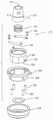
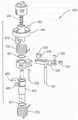
本发明的组件100的清洁模块602(如图45-48所示)包括基部604,其中外壳660被可移除地附接到该基部。基部604和外壳660共同形成清洁模块602的壳体的基本部分。带槽螺杆690被可旋转地安装到基部604且被设置于外壳660中。剃刮管724环绕带槽螺杆690。在本发明的所示型式中,剃刮管724被安装到支靠在基部604的向上指向表面上的板710上。板710和剃刮管724被装配到清洁模块以便能够在基部604上旋转。在模块的壳体内,保持架764环绕带槽螺杆和剃刮管724。保持架764被在臂750的自由端处定位。臂750具有利于将该臂联接到组件的基部102的臂联接器436的特征。Cleaning module 602 ofassembly 100 of the present invention (shown in FIGS. 45-48 ) includes a base 604 to whichhousing 660 is removably attached. Thebase 604 and thehousing 660 together form an essential part of the housing of thecleaning module 602 . Slottedscrew 690 is rotatably mounted tobase 604 and disposed withinhousing 660 . Shavingtube 724 surroundsgrooved screw 690 . In the version of the invention shown, the shavingtube 724 is mounted to aplate 710 which rests on an upwardly directed surface of thebase 604 .Plate 710 and shavingtube 724 are mounted to the cleaning module so as to be able to rotate onbase 604 . Inside the housing of the module, acage 764 surrounds the slotted screw and shavingtube 724 . Acage 764 is positioned at the free end of thearm 750 . Thearm 750 has a feature that facilitates coupling the arm to thearm coupler 436 of thebase 102 of the assembly.

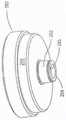
帽盖680被设置于外壳660上。帽盖680是清洁模块602的壳体的一部分。帽盖680限定在外壳660上方的汇集空间682。汇集空间682是模块壳体内部的接收从骨料清洁出的软组织的空间。毂状件850被设置于汇集空间682中。毂状件850使带槽螺杆680和剃刮管724保持稳定。Thecap 680 is disposed on thehousing 660 .Cap 680 is part of the housing ofcleaning module 602 .Cap 680 defines a poolingspace 682 abovehousing 660 . Thecollection space 682 is the space inside the module housing that receives the soft tissue cleaned from the aggregate. Thehub 850 is disposed in the collectingspace 682 . Thehub 850 stabilizes the slottedscrew 680 and shavingtube 724 .

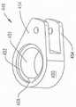
如图49和50中可见的清洁模块的基部604是单件式部件。基部604包括平坦的板606。板606的形状近似于组件的基部的顶板122的形状。内部边沿608从基部的板606的外周边向下延伸。外部边沿610环绕内部边沿608向下和向外延伸。基部604被形成为使得在将清洁模块602座置到组件的基部102上时,与模块602成一体的外部边沿610抵靠在与组件的基部102成一体的边沿116上座置。Thebase 604 of the cleaning module as seen in Figures 49 and 50 is a one-piece component. Thebase 604 includes aflat plate 606 . The shape of theplate 606 approximates the shape of thetop plate 122 of the base of the assembly. Aninner rim 608 extends downwardly from the outer perimeter of thebase plate 606 . Theouter rim 610 extends downwardly and outwardly around theinner rim 608 . Thebase 604 is formed such that when thecleaning module 602 is seated onto the assembly'sbase 102, theouter rim 610 integral with themodule 602 seats against theintegral rim 116 of the assembly'sbase 102.

清洁模块的基部604被进一步形成为使得四个槽612延伸穿过基部的外部边沿610,图中标示出两个槽。槽612被定位和成形为使得在将清洁模块602座置到组件的基部102上时,与组件的基部的闩锁组件540成一体的每个凸片546与槽中的单独一个槽对齐且可座置于其中。基部604被进一步形成为使得槽614延伸穿过内部边沿608。槽614延伸穿过边沿608的弯曲的端部区段之一的一部分。槽614延伸入板606中一段短的距离。基部604也被形成有凹口615,该凹口在板606中形成空隙。凹口615从板606的与槽614相反的一部分向内延伸。Thebase 604 of the cleaning module is further formed such that fourslots 612 extend through theouter edge 610 of the base, two slots being labeled. Theslots 612 are positioned and shaped such that when thecleaning module 602 is seated onto thebase 102 of the assembly, eachtab 546 integral with thelatch assembly 540 of the base of the assembly is aligned with a separate one of the slots and can seat in it. Thebase 604 is further formed such that aslot 614 extends through theinner rim 608 .Slot 614 extends through a portion of one of the curved end sections ofrim 608 .Slot 614 extends intoplate 606 for a short distance. Thebase 604 is also formed with anotch 615 that forms a void in theplate 606 .Notch 615 extends inwardly from a portion ofplate 606opposite slot 614 .

模块的基部604被进一步形成为具有两个开口622和630。开口622被定位成使得在将模块602座置在组件基部102上时,该开口被设置于主联接器194和管联接器348上。基部604被进一步形成为使得在板606的顶表面上使圆形的凹陷表面623环绕开口622居中且环绕该开口沿周向延伸。模块的基部604被形成为具有从板606的底侧环绕开口622向下延伸的外部环624。内部环626从外部环624的向下指向表面向下延伸。外部环624和内部环626具有相同的直径,即开口622的直径。内部环626的外径小于外部环624的外径。模块的基部604被进一步形成为使得在将模块602座置在组件基部102上时,内部环的暴露的圆面被设置成抵靠在顶板122的环绕开口124的表面上。基部604被进一步形成为具有多个膛孔628,图中标示出了一个膛孔,该膛孔从外部环624的被紧接外部环622径向向外定位的圆面向内延伸。Thebase 604 of the module is further formed with twoopenings 622 and 630 . Theopening 622 is positioned such that when themodule 602 is seated on theassembly base 102 , the opening is disposed on themain coupler 194 and thepipe coupler 348 . Thebase 604 is further formed such that a circular recessedsurface 623 is centered on the top surface of theplate 606 around theopening 622 and extends circumferentially around the opening. Thebase 604 of the module is formed with anouter ring 624 extending downwardly from the bottom side of theplate 606 around theopening 622 . Aninner ring 626 extends downwardly from the downwardly-pointing surface of theouter ring 624 .Outer ring 624 andinner ring 626 have the same diameter, ie the diameter ofopening 622 . The outer diameter of theinner ring 626 is smaller than the outer diameter of theouter ring 624 . The base of themodule 604 is further formed such that when themodule 602 is seated on theassembly base 102 , the exposed circular face of the inner ring is positioned against the surface of thetop plate 122 surrounding theopening 124 . Thebase 604 is further formed with a plurality ofbores 628 , one bore being indicated, extending inwardly from a circular surface of theouter ring 624 positioned radially outwardly from theouter ring 622 .

开口630被形成于板606中,以使得在将模块602座置在组件基部上时,开口630与形成于顶板122中的开口126配准。基部604被进一步形成为使得具有在板606的顶表面上方延伸一段短的距离的岛状部631。基部604被成形为使得岛状部631环绕开口630。Opening 630 is formed inplate 606 such that whenmodule 602 is seated on the assembly base, opening 630 registers with opening 126 formed intop plate 122 . Thebase 604 is further formed so as to have anisland 631 extending a short distance above the top surface of theplate 606 . Thebase 604 is shaped such that theisland 631 surrounds theopening 630 .

模块的基部604被进一步形成为使得两个锁定止挡件632和638从板606的底表面向下突出。止挡件632和638被离开开口622的中心一段共同的径向距离定位。止挡件632和638彼此拱形地间隔开大约90°。小的肋从板606的底表面毗邻每个止挡件632和636向下突出。肋634被毗邻止挡件632定位。肋636被毗邻止挡件638定位。肋634和638位于开口622周围的同一个圆上,其中止挡件632和636被环绕开口622定位。肋634和636并未从板606的底表面向下延伸到与止挡件632和638向下延伸的程度相同的程度。基部604被进一步形成为使得在垂直于沿着肋634和636的纵向轴线的平面中,肋具有凸面形状。Thebase 604 of the module is further formed such that two locking stops 632 and 638 protrude downwardly from the bottom surface of theplate 606 .Stops 632 and 638 are positioned a common radial distance from the center ofopening 622 .Stops 632 and 638 are arcuately spaced approximately 90° from each other. Small ribs protrude downwardly from the bottom surface ofplate 606 adjacent eachstop 632 and 636 .Rib 634 is positionedadjacent stop 632 .Rib 636 is positionedadjacent stop 638 .Ribs 634 and 638 lie on the same circle around opening 622 around whichstoppers 632 and 636 are positioned.Ribs 634 and 636 do not extend down from the bottom surface ofplate 606 to the same extent that stops 632 and 638 do. Thebase 604 is further formed such that, in a plane perpendicular to the longitudinal axis along theribs 634 and 636 , the ribs have a convex shape.

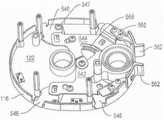
图47和48中最佳可见的模块的外壳650被形成为具有外壁652。外壁652被成形为坐放于在基部604的相应的内边沿608与外边沿610之间的外部台阶部上。外壁652被进一步成形为环绕基部延伸以便环绕基部的周边的大致70%延伸。更具体地讲,外壁652并不对着基部的最接近开口622的弯曲端。在外壁652并不对着模块的基部604的台阶表面时,外壳650被成形为具有内壁656。外壳650被成形为使得内壁656被从外壁652径向向内地定位。外壳650被进一步形成为使得毗邻内壁656的顶部存在向内延伸的沟槽655。沟槽655沿着壁656的长度自右至左延伸。端部面板654从外壁652的相对端向内延伸到外壁656的毗邻端。外壳650被进一步形成为使得内壁656并不延伸外壁652的整个长度。尽管壁652和656的顶部大体在同一平面中,但内壁656仅延伸内壁652向下延伸的距离的大致三分之一。Thehousing 650 of the module, best seen in FIGS. 47 and 48 , is formed with anouter wall 652 . Theouter wall 652 is shaped to sit on the outer step between the respectiveinner edge 608 andouter edge 610 of thebase 604 . Theouter wall 652 is further shaped to extend around the base so as to extend around approximately 70% of the circumference of the base. More specifically,outer wall 652 does not face the curved end of the base that is closest to opening 622 . While theouter wall 652 is not facing the stepped surface of thebase 604 of the module, thehousing 650 is shaped to have aninner wall 656 .Housing 650 is shaped such thatinner wall 656 is positioned radially inward fromouter wall 652 . Thehousing 650 is further formed such that adjacent the top of theinner wall 656 there is an inwardly extendinggroove 655 .Groove 655 extends from right to left along the length ofwall 656 .End panels 654 extend inwardly from opposite ends ofouter wall 652 to adjacent ends ofouter wall 656 .Housing 650 is further formed such thatinner wall 656 does not extend the entire length ofouter wall 652 . Although the tops ofwalls 652 and 656 are generally in the same plane,inner wall 656 only extends approximately one third of the distance thatinner wall 652 extends downward.

外壳650还具有两个凸片653,图48中标示出一个凸片。凸片653从外壁652的底部向内延伸。凸片653被毗邻壁652的相对端定位。在外壳650座置在基部604上时,一个凸片653被在槽614下方定位。相对的凸片653被在凹口615下方定位。Thehousing 650 also has twotabs 653, one of which is labeled in FIG.Tabs 653 extend inwardly from the bottom ofouter wall 652 . Thetab 653 is located adjacent the opposite end of thewall 652 . Atab 653 is positioned below theslot 614 when thehousing 650 is seated on thebase 604 . The opposingtab 653 is positioned below thenotch 615 .

三个腹板658、660和666在外壁652的相对端之间延伸。腹板658大体竖直地对准且被从内壁656向外地定位。腹板658从端部面板654中的一个弯曲到相对的端部面板654。腹板658的底边缘被在外壁652的底边缘上方定位。腹板658的顶边缘被在内壁656的顶边缘下方定位。Threewebs 658 , 660 and 666 extend between opposite ends of theouter wall 652 .Web 658 is generally vertically aligned and positioned outwardly frominner wall 656 . Aweb 658 is bent from one of theend panels 654 to theopposite end panel 654 . The bottom edge ofweb 658 is positioned above the bottom edge ofouter wall 652 . The top edge of theweb 658 is positioned below the top edge of theinner wall 656 .

腹板660从腹板658的顶部向上和向内延伸。腹板666从腹板660向内和向上延伸。外壳650被形成为使得腹板666的外周边、腹板666的最接近腹板660的部分在腹板660的内周边下方形成台阶。腹板666延伸到内壁656的底部。腹板658、660和666是拱形的且对着外壁652的端部之间的间隙。外壳650被进一步形成为使得两个肋661和662向上突出且延伸腹板660的宽度。肋661被离开外壳端部面板654中的第一端部面板一段短距离定位。肋662被离开相对的外壳端部面板654一段短距离定位。肋661和662各自从腹板660的外周边延伸到腹板660的内周边。Web 660 extends upwardly and inwardly from the top ofweb 658 .Web 666 extends inwardly and upwardly fromweb 660 .Shell 650 is formed such that the outer perimeter ofweb 666 , the portion ofweb 666 closest toweb 660 , steps below the inner perimeter ofweb 660 .Web 666 extends to the bottom ofinner wall 656 .Webs 658 , 660 and 666 are arcuate and face the gap between the ends ofouter wall 652 . Theshell 650 is further formed such that tworibs 661 and 662 protrude upwards and extend the width of theweb 660 . Therib 661 is located a short distance away from a first of thehousing end panels 654 . Therib 662 is positioned a short distance from the opposinghousing end panel 654 .Ribs 661 and 662 each extend from the outer periphery ofweb 660 to the inner periphery ofweb 660 .

清洁模块的外壳650包括盖板670。盖板670被在外壳的外壁652和内壁654上方定位。开口672被形成于盖板670中。凸台676从盖板670的底表面向下延伸。外壳650被形成为使得在将外壳设置于模块基部604上时,外壳开口672在基部开口622上居中,且凸台676在基部开口630上居中。三个凸台673(图中标示出一个凸台)从盖板679的顶表面向上延伸。凸台673环绕外壳开口672的中心居中,且与该开口的外周边径向间隔开。凸台673彼此等角度地间隔开。Thehousing 650 of the cleaning module includes acover plate 670 .Cover plate 670 is positioned overouter wall 652 andinner wall 654 of the housing. Anopening 672 is formed in thecover plate 670 . Theboss 676 extends downward from the bottom surface of thecover plate 670 .Housing 650 is formed such thathousing opening 672 is centered over base opening 622 andboss 676 is centered over base opening 630 when the housing is positioned onmodule base 604 . Three bosses 673 (one boss is labeled) extend upwardly from the top surface of the cover plate 679 .Boss 673 is centered around the center ofhousing opening 672 and spaced radially from the outer periphery of the opening. Thebosses 673 are equiangularly spaced apart from each other.

帽盖680也形成清洁模块602的壳体的一部分。帽盖680被设置于盖板670上。帽盖680固定到盖板670的方式并非本发明的部分。盖板670因此形成由帽盖680限定的汇集空间682的基部。盖板670中的开口672通到汇集空间682中。Thecap 680 also forms part of the housing of thecleaning module 602 . Thecap 680 is disposed on thecover plate 670 . The manner in which thecap 680 is secured to thecover plate 670 is not part of the invention. Thecover plate 670 thus forms the base of the collectingspace 682 delimited by thecap 680 . Anopening 672 in thecover plate 670 leads into a collectingspace 682 .

由弹性体材料形成的环681环绕帽盖680的顶部延伸。环682被设置成利于抓持整合的外壳650和帽盖680单元。Aring 681 of elastomeric material extends around the top of thecap 680 .Ring 682 is configured to facilitate gripping theintegrated housing 650 andcap 680 unit.

图51中可见的带槽螺杆690被可旋转地安装到基部的板606。螺杆690包括圆柱形的杆692。在从杆的底部向上大致五分之一处开始的位置处,槽694(图中标示出一个槽)环绕杆692螺旋地延伸。槽694延伸到杆692的顶部。每个槽694被形成为限定一个切刃696,图中标示出一个切刃。通过从杆692的基部向上延伸,螺杆690被形成为具有图51中可见的闭端膛孔698。膛孔698被设定尺寸以接收与主联接器194成一体的销198。带槽螺杆690被进一步形成为具有三个等角度间隔开的凹口702,该凹口从杆692的基部向上延伸,图中标示出一个凹口。每个凹口702从杆692的外周边延伸到膛孔698。凹口702并不像膛孔698一样在杆692上向上延伸那么远。凹口702具有共同的宽度。每个凹口702足够宽以使得与主联接器194成一体的齿202可座置在该凹口中。带槽螺杆690被进一步形成为使得在图46中可见的闭端膛孔704从杆692的顶部向下延伸。膛孔698和704与穿过杆692的纵向轴线共轴。A slottedscrew 690, visible in FIG. 51, is rotatably mounted to theplate 606 of the base.Screw 690 includes acylindrical shaft 692 . Slots 694 (one slot is labeled) extend helically around therod 692 at a location approximately one-fifth upward from the bottom of the rod.Slot 694 extends to the top ofrod 692 . Eachslot 694 is formed to define acutting edge 696, with one cutting edge indicated.Screw 690 is formed with a closed end bore 698 visible in FIG. 51 by extending upwardly from the base ofrod 692 .Bore 698 is sized to receivepin 198 integral withmain coupler 194 . The slottedscrew 690 is further formed with three equally angularly spacednotches 702 extending upwardly from the base of therod 692, one notch being indicated. Eachnotch 702 extends from the outer periphery of therod 692 to thebore 698 . Thenotch 702 does not extend as far up therod 692 as thebore 698 does.Notches 702 have a common width. Eachnotch 702 is wide enough that atooth 202 integral with themain coupler 194 can seat in the notch. The slottedscrew 690 is further formed such that a closed end bore 704 visible in FIG. 46 extends downwardly from the top of therod 692 .Bores 698 and 704 are coaxial with the longitudinal axis passing throughrod 692 .

图46和51中可见的旋转板710(有时在图中标示为翻转板710)被座置在模块的板606上。翻转板710的顶表面的形状是基本平坦的。凸台712从翻转板710的底表面向下延伸。凸台712具有允许凸台座置在形成于模块的基部604中的开口622中并在其中旋转的直径。膛孔714从凸台712的底部穿过凸台向上延伸到板710的顶表面。在凸台712的底端,沉孔716环绕膛孔714径向向外地延伸。沉孔716具有比管联接器348的直径小大约2mm的直径。板710被进一步形成为具有三个等角度间隔开的凹口718。凹口718从沉孔716的外周边径向向外地延伸。每个凹口718能够接收与管联接器348成一体的齿353中的单独一个齿。The swivel plate 710 (sometimes labeled asflip plate 710 in the figures) visible in Figures 46 and 51 is seated on theplate 606 of the module. The shape of the top surface of theturnover plate 710 is substantially flat. Theboss 712 extends downward from the bottom surface of theturnover plate 710 .Boss 712 has a diameter that allows the boss to seat and rotate withinopening 622 formed inbase 604 of the module.Bore 714 extends from the bottom ofboss 712 up through the boss to the top surface ofplate 710 . At the bottom end of theboss 712 , acounterbore 716 extends radially outwardly around thebore 714 .Counterbore 716 has a diameter approximately 2 mm smaller than the diameter ofpipe coupler 348 .Plate 710 is further formed with three equally angularly spacednotches 718 . Thenotch 718 extends radially outward from the outer perimeter of thecounterbore 716 . Eachnotch 718 is capable of receiving a single one of theteeth 353 integral with thepipe coupler 348 .

环720也从板710的底表面向下突出。环720与凸台712共轴并与其径向向外地间隔开。环720的外径稍微小于凹面623的环绕模块的基部604内部的开口622的外周边的直径。在组装清洁模块602时,板710座置在板606上,使得凸台712能够在开口622中旋转。环720被紧接限定了从凹陷表面623到板604的环绕部分的过渡的台阶部内侧定位。环720因此最大限度减小清洁模块602中的翻转板710的侧向摇晃。Ring 720 also protrudes downward from the bottom surface ofplate 710 .Ring 720 is coaxial withboss 712 and spaced radially outward therefrom. The outer diameter of thering 720 is slightly smaller than the diameter of the outer perimeter of theconcave surface 623 surrounding theopening 622 inside thebase 604 of the module. When cleaningmodule 602 is assembled,plate 710 is seated onplate 606 such thatboss 712 can rotate withinopening 622 . Thering 720 is positioned immediately inboard of the step defining the transition from the recessedsurface 623 to the surrounding portion of theplate 604 .Ring 720 thus minimizes sideways rocking offlip plate 710 incleaning module 602 .

图46中最佳可见的剃刮管724从板710内部的膛孔714向上延伸。管724被进一步成形为具有窗口728。窗口728延伸到管腔中,该管腔轴向地延伸穿过该管且环绕穿过管724的纵向轴线沿直径彼此相对。窗口728由形成于管724中的两个拱形地间隔开且纵向延伸的切刃726限定,图中标示出一个切刃。每个切刃726是由管的内壁与一个侧表面的交线限定的边缘,该侧表面从管的外壁向内延伸以限定相关联的窗口728的侧周边。形成清洁模块602的部件共同地被成形为使得在螺杆槽694的边缘696与形成于管724中的切刃726之间存在介于0.03与0.5mm之间的间隙。Shavingtube 724 , best seen in FIG. 46 , extends upwardly frombore 714 insideplate 710 .Tube 724 is further shaped withwindow 728 .Windows 728 extend into lumens that extend axially through the tube and are diametrically opposed to each other about a longitudinal axis throughtube 724 . Thewindow 728 is defined by two arcuately spaced apart longitudinally extendingcutting edges 726 formed in thetube 724 , one of which is indicated. Eachcutting edge 726 is an edge defined by the intersection of the inner wall of the tube with a side surface extending inwardly from the outer wall of the tube to define the side perimeter of the associatedwindow 728 . The components forming thecleaning module 602 are collectively shaped such that there is a gap between 0.03 and 0.5 mm between theedge 696 of thescrew channel 694 and thecutting edge 726 formed in thetube 724 .

剃刮管724被按压装配到翻转板710内部的膛孔714中。剃刮管724被安装到板710,使得窗口728的底端与该板的顶表面基本齐平。The shavingtube 724 is press fit into thebore 714 inside theflip plate 710 . The shavingtube 724 is mounted to theplate 710 such that the bottom end of thewindow 728 is substantially flush with the top surface of the plate.

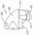
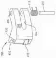
图52-55中最佳可见的臂750和保持架764被形成为单件式单元。臂750呈细长杆的形式。臂750的一端是修圆的。臂750的顶部中模制有空腔752。空腔752被用作用以提供可由模块602清洁的骨料的最大尺寸的可视表示的标准指导。Arm 750 andcage 764, best seen in Figures 52-55, are formed as a one-piece unit.Arm 750 is in the form of an elongated rod. One end of thearm 750 is rounded. Acavity 752 is molded into the top of thearm 750 .Cavity 752 is used as a standard guide to provide a visual representation of the maximum size of aggregate that can be cleaned bymodule 602 .

臂750被形成为使得在臂的修圆端向内的位置存在第一膛孔754和第二膛孔756,该些膛孔可从臂的底部进入。膛孔754的形状是圆形的,且从臂750的底表面向上延伸。膛孔754通到膛孔756中。膛孔756在平行于穿过膛孔756的纵向轴线的剖面中大致呈修圆的三角形的形状。膛孔756的剖面对着小于膛孔754的横截面积的面积。臂中的处于膛孔754和膛孔756之间的台阶部未标示出。膛孔756是闭端的。仅在图53中以虚线可见的闭端圆柱形膛孔757从膛孔756的闭端的顶部向上延伸。Thearm 750 is formed such that at a location inward of the rounded end of the arm there is afirst bore 754 and asecond bore 756 which are accessible from the bottom of the arm. Thebore 754 is circular in shape and extends upward from the bottom surface of thearm 750 .Bore 754 opens intobore 756 . Thebore 756 is generally in the shape of a rounded triangle in a section parallel to the longitudinal axis through thebore 756 . The cross-sectional area of thebore 756 faces an area smaller than the cross-sectional area of thebore 754 . The step in the arm betweenbore 754 and bore 756 is not labeled. Thebore 756 is closed ended. A closed-endedcylindrical bore 757 , visible only in phantom in FIG. 53 , extends upwardly from the top of the closed end ofbore 756 .

臂750被进一步形成为使得具有图54中标示出的从臂的顶表面向内延伸的凹窝758。凹窝758是凹面形状的。凹窝758被形成于臂中以便与孔754同心。臂750被形成为使得在将外壳650装配到基部604上,外壳凸台676被座置在凹窝758中。图中可见,空隙759从臂750的底表面向上延伸。空隙759与膛孔754和756分离开。空隙759仅出于制造原因而存在。Thearm 750 is further formed so as to have adimple 758 indicated in FIG. 54 extending inwardly from the top surface of the arm.Dimple 758 is concave in shape. Adimple 758 is formed in the arm so as to be concentric with thehole 754 .Arm 750 is formed such thathousing boss 676 is seated inrecess 758 upon assembly ofhousing 650 tobase 604 . As can be seen, void 759 extends upwardly from the bottom surface ofarm 750 . A void 759 separates bores 754 and 756 .Void 759 exists only for manufacturing reasons.

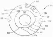
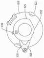
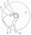
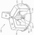
保持架764是大体被形成为具有修圆的顶点的三角形的结构。保持架764从臂750的与臂的弯曲端相反的端部向外延伸。臂750和保持架764被形成为使得保持架764的相对短长度的面板766沿着大致平行于臂的纵向轴线的线延伸。保持架的中等长度的面板768大致垂直地从短长度的面板延伸且毗邻臂750。保持架的最长长度的面板770(基本上是作为由保持架形成的三角形的斜边的那个面板)在面板766和768的自由端之间延伸。保持架面板770与臂750间隔开。Thecage 764 is generally formed as a triangular structure with rounded vertices. Aretainer 764 extends outwardly from the end of thearm 750 opposite the bent end of the arm.Arm 750 andcage 764 are formed such that a relatively short length ofpanel 766 ofcage 764 extends along a line generally parallel to the longitudinal axis of the arm. The medium-length panel 768 of the cage extends generally perpendicularly from the short-length panel and adjoins thearm 750 . Thelongest length panel 770 of the cage (essentially the one that is the hypotenuse of the triangle formed by the cage) extends between the free ends ofpanels 766 and 768 .Cage panel 770 is spaced apart fromarm 750 .

保持架764被形成为具有从面板766-770的表面向内延伸到保持架内部的空隙空间765内的结构特征。这些结构之一是面板770中的凹陷769。凹陷769被毗邻面板768和770之间的弯曲顶点定位。凹陷769呈现为延伸到空隙空间765中。Thecage 764 is formed with structural features extending inwardly from the surfaces of the panels 766-770 into avoid space 765 inside the cage. One of these structures is adepression 769 in thepanel 770 .Recess 769 is positioned adjacent to the curved apex betweenpanels 768 and 770 .Recess 769 appears to extend intovoid space 765 .

延伸到空隙空间765中的第二结构特征是压块772。压块772由面板768的若干部分和形成保持架的介于面板768和面板770之间的区段的毗邻弯曲顶点的部分构成。压块772具有被在面板768的内表面和毗邻的弯曲顶点向内定位的面。保持架764被形成为使得压块772从面板的底边缘向上延伸。压块772向上延伸保持架的从顶至底的距离的大致一半的距离。压块772朝向保持架限定的空隙空间呈现为弯曲的面。更具体地讲,压块772是弯曲的,使得该面具有在垂直于沿着压块的从顶至底的纵向轴线的平面中是凹的曲率。A second structural feature extending intovoid space 765 ispressure block 772 .Pressure block 772 is formed from portions ofpanel 768 and the portion adjacent to the curved apex forming the section of the cage betweenpanel 768 andpanel 770 . Thepressure block 772 has a face positioned inwardly of the inner surface of thepanel 768 and the adjacent curved apex. Theretainer 764 is formed such that apressure block 772 extends upwardly from the bottom edge of the panel. Thepressure block 772 extends upwardly a distance of approximately half the distance from the top to the bottom of the cage. Thepressure piece 772 presents a curved face towards the void space defined by the cage. More specifically, the compact 772 is curved such that the face has a curvature that is concave in a plane perpendicular to the longitudinal axis along the top to bottom of the compact.

保持架764的突出到空隙空间765中的第三结构特征是从面板768的内表面向内延伸的肋776。肋776具有在垂直于沿着面板766的从顶至底的轴线的平面中是三角形的形状。沿着肋776的顶点线是肋的与面板766间隔开最远的一部分。肋776并不具有仅从面板768的底部垂直地向上延伸的纵向轴线。而是,在面板的底部,肋776的基部被在由臂750对着的区域内定位。从面板768的该部分向上延伸,肋776朝向保持架的面板768和770之间的弯曲顶点对角地延伸。因此,肋776的顶部与面板768的与臂750间隔开的区段成一体。A third structural feature ofcage 764 that protrudes intovoid space 765 is arib 776 that extends inwardly from the inner surface ofpanel 768 . Therib 776 has a triangular shape in a plane perpendicular to the top-to-bottom axis along thepanel 766 . Along the apex line ofrib 776 is the portion of the rib that is spaced farthest frompanel 766 .Rib 776 does not have a longitudinal axis extending vertically upward only from the bottom ofpanel 768 . Instead, at the bottom of the panel, the base of therib 776 is positioned in the area opposed by thearm 750 . Extending upwardly from this portion of thepanel 768, arib 776 extends diagonally towards the curved apex between thepanels 768 and 770 of the cage. Thus, the top of therib 776 is integral with the section of thepanel 768 that is spaced from thearm 750 .

肋780是保持架764的延伸到空隙765中的第四结构构件。肋780从面板766的内表面和面板766与面板770之间的弯曲顶点向内延伸。在沿着保持架764从顶至底竖直延伸的平面中,肋780具有大体三角形的横截面形状。保持架764被进一步形成为使得肋780的顶点沿着并不平行于保持架底部的线延伸。而是,保持架被形成为使得肋780的从面板766向外延伸的端部从大体在面板766的顶部与底部之间的中间区段附近的位置处向外突出。随着肋远离面板768延伸且环绕通向面板770的顶点弯曲,该肋向上延伸。肋780的第二端因此终止于保持架的顶边缘处的使得面板768与770之间的顶点弯曲到面板770中的位置。肋780在肋的顶点下方具有表面782。表面782从面板766和面板766与770之间的顶点向上渐缩。从顶点771远离面板770弯曲的地方开始,表面782环绕该顶点且沿绕着该顶点向下弯曲。随着表面782沿着面板766延伸,表面782从该顶点向下延伸。Rib 780 is a fourth structural member ofcage 764 that extends intovoid 765 .Ribs 780 extend inwardly from the inner surface ofpanel 766 and the apex of the bend betweenpanel 766 andpanel 770 . In a plane extending vertically from top to bottom along thecage 764, therib 780 has a generally triangular cross-sectional shape. Thecage 764 is further formed such that the vertices of theribs 780 extend along a line that is not parallel to the bottom of the cage. Rather, the cage is formed such that the ends of theribs 780 extending outward from thepanel 766 protrude outward from a location generally near the middle section between the top and bottom of thepanel 766 . The rib extends upwardly as it extends away from thepanel 768 and curves around the apex leading to thepanel 770 . The second end ofrib 780 thus terminates at a position at the top edge of the cage such that the apex betweenpanels 768 and 770 bends intopanel 770 . Therib 780 has asurface 782 below the apex of the rib.Surface 782 tapers upwardly frompanel 766 and the apex betweenpanels 766 and 770 . From where apex 771 curves away frompanel 770,surface 782 wraps around and curves down around that apex.Surface 782 extends downwardly from the apex assurface 782 extends alongpanel 766 .

腹板790在臂750的外侧与保持架的面板768的远离该臂突出的外表面之间延伸。凸片792从保持架764的顶部向外延伸。更具体地讲,凸片792从顶点769的顶部向外突出。凸片792被形成有箭头形状的图标794,该图标指向远离保持架764的方向。Web 790 extends between the outer side ofarm 750 and the outer surface offace plate 768 of the cage that projects away from the arm.Tabs 792 extend outwardly from the top ofcage 764 . More specifically,tab 792 protrudes outwardly from the top ofapex 769 . Thetab 792 is formed with an arrow shapedicon 794 pointing away from theretainer 764 .

在图56和57中最佳可见的驱动销802被安装到臂750且从该臂向外延伸。驱动销802包括圆柱形的杆804。杆804被设定尺寸以座置在形成于臂750中的膛孔754中。杆804的直径大致等于臂联接器486的头部490的直径,该臂联接器是组件的基部102的一部分。头部806从销802的杆804向上延伸。头部806是三角形形状,且对着位于杆804限定的圆内的横截面面积。销的头部806被设定尺寸以紧配合在形成于臂750中的膛孔756中。Drive pin 802 , best seen in FIGS. 56 and 57 , is mounted to and extends outwardly fromarm 750 .Drive pin 802 includes acylindrical rod 804 .Rod 804 is sized to seat withinbore 754 formed inarm 750 . The diameter of therod 804 is approximately equal to the diameter of thehead 490 of thearm coupler 486 which is part of thebase 102 of the assembly.Head 806 extends upwardly fromshank 804 ofpin 802 .Head 806 is triangular in shape and subtends a cross-sectional area within the circle defined bystem 804 . Thehead 806 of the pin is sized to fit snugly in thebore 756 formed in thearm 750 .

驱动销802被进一步形成为使得在杆804的基部处,即该杆的与头部806从其延伸的端部相反的端部,两个趾部808远离该杆延伸。趾部808位于共同的平面中。趾部808彼此拱形地间隔开。驱动销802被成形以使得每个趾部808具有基本上远离形成销的杆804的外表面的弯曲壁沿切线方向延伸的外侧表面。Thedrive pin 802 is further formed such that at the base of therod 804, ie the end of the rod opposite the end from which thehead 806 extends, twotoes 808 extend away from the rod.Toes 808 lie in a common plane.Toes 808 are arcuately spaced from one another. The drive pins 802 are shaped such that eachtoe 808 has an outer side surface that extends substantially tangentially away from the curved wall of the outer surface of therod 804 forming the pin.

驱动销802被进一步形成为使得具有从杆810的基部向上延伸的槽810。槽810是矩形形状,且被设定尺寸以接收与组件的基部的臂联接器586成一体的条状件492。在本发明的所示型式中,槽810稍微径向地超出杆810突出到趾部808之间的腹板中。膛孔812从杆804的限定槽810的顶的内表面向上延伸。膛孔812延伸穿过杆804和头部806。Thedrive pin 802 is further formed so as to have aslot 810 extending upwardly from the base of therod 810 . Theslot 810 is rectangular in shape and is sized to receive thestrip 492 integral with thearm coupler 586 of the base of the assembly. In the version of the invention shown, theslot 810 protrudes slightly radially beyond thestem 810 into the web between thetoes 808 .Bore 812 extends upwardly from the inner surface ofrod 804 defining the top ofslot 810 .Bore 812 extends throughstem 804 andhead 806 .

在组装清洁模块602时,臂750被定位成使得膛孔754和756位于模块基部604中的开口630上。作为臂750的定位的结果,保持架770被设置于板710上以环绕带槽螺杆690和环绕的管724。驱动销的杆804被插入到开口630中,使得杆和头部分别座置在形成于臂中的膛孔754和756中。仅在图46中可见的延伸穿过销的膛孔812和臂750内部的膛孔757的紧固件814将销802保持到臂750。与驱动销成一体的趾部808和槽810被毗邻板604的底表面定位,即板的与臂750支靠的表面相反的表面。When cleaningmodule 602 is assembled,arm 750 is positioned such that bores 754 and 756 are located over opening 630 inmodule base 604 . As a result of the positioning of thearms 750 , acage 770 is provided on theplate 710 to encircle thegrooved screw 690 and theencircling tube 724 . Theshaft 804 of the drive pin is inserted into theopening 630 such that the shaft and head seat respectively inbores 754 and 756 formed in the arms.Fastener 814 , visible only in FIG. 46 , extending throughpin bore 812 and bore 757 insidearm 750 holdspin 802 toarm 750 . Thetoe 808 and slot 810 integral with the drive pin are located adjacent to the bottom surface of theplate 604, ie the surface of the plate opposite the surface against which thearm 750 rests.

现在参照图60和61描述的锁定盘818被旋转地安装到模块基部604,以便被在板604的底表面下方定位。锁定盘包括圆形的板820。两个凸片822被设置于板820的顶表面上。凸片822相对于板的中心沿直径彼此相对。每个凸片822从板820的顶表面向上延伸。凸片822的被设置于板的顶表面上方的部分超出板820的周边径向向外突出。脊部824也从板820的顶表面向上延伸。脊部824是三区段的结构,各个区段在图中未标示出。中心区段被毗邻板820的周边定位。该中心区段是弯曲形状的,且对着大致20°到30°的弧。两个端部区段从中间区段的相反两端径向向外地突出。端部区段超出板的周边突出一段短的距离,大约5mm。脊部824因此限定了被毗邻板820的外周边的榫眼826定位。Lockingplate 818 , now described with reference to FIGS. 60 and 61 , is rotatably mounted tomodule base 604 so as to be positioned below the bottom surface ofplate 604 . The locking disc comprises acircular plate 820 . Twotabs 822 are provided on the top surface of theplate 820 . Thetabs 822 are diametrically opposed to each other with respect to the center of the plate. Eachtab 822 extends upwardly from the top surface of theplate 820 . The portion of thetab 822 disposed above the top surface of the plate protrudes radially outward beyond the perimeter of theplate 820 .Ridges 824 also extend upwardly from the top surface ofplate 820 .Ridge 824 is a three-segment structure, each of which is not shown in the figure. The central section is positioned adjacent the perimeter of theplate 820 . The central section is curved in shape and subtends an arc of approximately 20° to 30°. Two end sections project radially outwardly from opposite ends of the middle section. The end sections protrude a short distance, approximately 5 mm, beyond the periphery of the plate. Theridge 824 is thus defined and positioned by themortise 826 adjacent the outer periphery of theplate 820 .

锁定盘818被进一步形成为具有穿过膛孔826设置的中心。锁定盘818被形成为使得膛孔826具有使得模块的基部604的外部环624可座置在该膛孔中且盘818可环绕环624旋转的直径。与板820一体形成的环形岛状部828从板的顶表面向上延伸且环绕膛孔826延伸。环形岛状部828被形成为具有被与孔826的中心相距不同距离定位的外部侧表面。第一侧表面,即表面829(图中标示出其边缘)是被离孔826的中心最远地定位的拱形表面。环形岛状部被形成为使得表面829对着环绕环形岛状部828的周边延伸超过180°的弧。在一端处,表面829弯曲到表面830中。表面830沿着环绕孔826的大体线性形状的路径延伸。表面830合并到拱形表面,即表面832中。表面832环绕孔826的中心居中。相对于表面829,表面832被较接近于孔826定位。线性表面,即表面834,远离表面832拱形地且径向向外地延伸。表面834延伸到毗邻的线性表面,即表面836处。表面836被沿着大致平行于会出现在表面832上的切线(在表面832与834相交处出现)的线定位。表面838延伸到表面829。Lockingdisk 818 is further formed to have a center disposed throughbore 826 . Thelocking disc 818 is formed such that thebore 826 has a diameter such that theouter ring 624 of thebase 604 of the module can be seated in the bore and thedisc 818 can rotate about thering 624 . Anannular island 828 integrally formed withplate 820 extends upwardly from the top surface of the plate and aroundbore 826 . Theannular island 828 is formed to have outer side surfaces positioned at different distances from the center of thebore 826 . The first side surface, surface 829 (the edge of which is indicated in the figure), is the arcuate surface positioned furthest from the center of thehole 826 . The annular island is formed such that thesurface 829 subtends an arc extending over 180° around the perimeter of theannular island 828 . At one end,surface 829 curves intosurface 830 .Surface 830 extends along a generally linearly shaped path aroundaperture 826 .Surface 830 merges into an arcuate surface,surface 832 .Surface 832 is centered around the center ofhole 826 .Surface 832 is positioned closer toaperture 826 thansurface 829 . The linear surface,surface 834 , extends arcuately and radially outwardly away fromsurface 832 .Surface 834 extends to an adjacent linear surface,surface 836 .Surface 836 is positioned along a line substantially parallel to a tangent that would occur on surface 832 (occurring wheresurfaces 832 and 834 intersect). Surface 838 extends to surface 829 .

锁定环818被进一步形成为使得凸片839从环形岛状部828的表面828径向向外地延伸。凸片839被形成有凹陷840。凹陷840被设定尺寸以接收从模块的基部604向下延伸的肋634或636中的任一个。Lockingring 818 is further formed such thattabs 839 extend radially outward fromsurface 828 ofannular island 828 . Thetab 839 is formed with arecess 840 . Therecess 840 is dimensioned to receive either of theribs 634 or 636 extending downwardly from thebase 604 of the module.

环842从锁定盘818的底表面向下延伸。环842环绕孔826沿周向延伸。边沿844也从板824的底表面向下延伸。边沿844从盘818的外周边向下延伸。边沿844并不完全环绕板824的外周边沿周向延伸。该板具有对着大致介于30°与50°之间的弧的区段,该区段是不具有边沿的。边沿844的一端被形成为具有斜坡表面,即表面846。随着表面846拱形地延伸,该表面远离板824的表面朝向边沿844的最底部表面渐缩。Aring 842 extends downwardly from the bottom surface of thelocking disk 818 .Ring 842 extends circumferentially around bore 826 . Arim 844 also extends downwardly from the bottom surface of theplate 824 . Arim 844 extends downwardly from the outer periphery of thedisc 818 . Therim 844 does not extend circumferentially around the outer perimeter of theplate 824 completely. The plate has a section subtending an arc of approximately between 30° and 50°, which section is edgeless. One end of therim 844 is formed to have a sloped surface, asurface 846 . Assurface 846 extends arcuately, the surface of the surface away fromplate 824 tapers toward the bottom-most surface ofrim 844 .

锁定环818被进一步形成为具有从环842的底部指向面向上延伸的闭端膛孔847。膛孔847被在环的在脊部824上方的部分中定位。磁体848被设置于膛孔847中。Thelocking ring 818 is further formed with a closed-endedbore 847 extending upwardly from the bottom pointing surface of thering 842 . Thebore 847 is located in the portion of the ring above theridge 824 . Amagnet 848 is disposed in thebore 847 .

清洁模块602是通过将锁定盘818毗邻基部604的底侧定位以使得外部环624座置在膛孔826中且向下延伸超出圆盘一段短的距离来组装的。由于锁定盘的这种定位,与驱动销802成一体的趾部808被设置在盘的毗邻环形岛状部828的表面上。保持环849被座置成靠在与模块的基部604成一体的环624和626之间的台阶表面上。紧固件851(图72中标示出一个)延伸穿过环849中的膛孔和基部中的膛孔628以将环保持到基部。环849具有大于锁定盘818内部的孔826的直径的外径。环846因此在与模块的基部604成一体的环842下方突出。环849因此将锁定盘保持到模块的基部604。在组装清洁模块时,锁定盘818在板606的底表面下方间隔开。凸片822和榫眼826被设置在板606和盘818之间的空间中。榫眼826可通过与模块的基部604成一体的环608中的槽614进入。Thecleaning module 602 is assembled by positioning thelocking disc 818 adjacent the underside of the base 604 such that theouter ring 624 is seated in thebore 826 and extends downward beyond the disc a short distance. Due to this positioning of the locking disc, thetoe 808 integral with thedrive pin 802 is provided on the surface of the disc adjacent theannular island 828 . Retainingring 849 is seated against the stepped surface betweenrings 624 and 626 integral withbase 604 of the module. Fasteners 851 (one labeled in FIG. 72 ) extend through bores inring 849 and bores 628 in the base to retain the ring to the base.Ring 849 has an outer diameter that is larger than the diameter ofbore 826 inside lockingdisc 818 . Thering 846 thus protrudes below thering 842 integral with thebase 604 of the module. Thering 849 thus holds the locking disc to thebase 604 of the module. Thelocking disc 818 is spaced below the bottom surface of theplate 606 when the cleaning module is assembled.Tab 822 andmortise 826 are disposed in the space betweenplate 606 anddisc 818 . Themortise 826 is accessible through theslot 614 in thering 608 integral with thebase 604 of the module.

图58和59中最佳可见的毂状件860被设置于清洁模块602内部的汇集空间682中。毂状件860是单件式部件。毂状件860具有盘形的基部862。基部862被形成有在基部的相反的向下指向表面和向上指向表面之间延伸的中心开口864。基部862的向下指向表面应被理解为面向下伏(underlying)的外壳盖板670的表面。三个膛孔868(图中标示出一个)相对于开口864径向向外地间隔且彼此等角度间隔开,该膛孔也在基部862的相反的向下指向表面和向上指向表面之间延伸。每个膛孔868具有一个沉孔(图中未标示出沉孔)。毂状件860被成形为使得在基部862被定位成使得毂状件的中心开口864被设置于外壳盖板670中的开口672上时,形成于盖板670中的凸台673中的每一个座置在与膛孔868相关联的沉孔中的单独一个中。延伸穿过盖板的凸台和毂状件的膛孔868的紧固件将毂状件保持到外壳的盖板670的顶部,图中未示出紧固件。The hub 860 , best seen in FIGS. 58 and 59 , is disposed in thecollection space 682 inside thecleaning module 602 . Hub 860 is a one-piece component. The hub 860 has a disc-shapedbase 862 . Thebase 862 is formed with acentral opening 864 extending between opposing downwardly and upwardly directed surfaces of the base. The downwardly directed surface of thebase 862 is to be understood as the surface facing theunderlying housing cover 670 . Three bores 868 (one labeled) spaced radially outward relative toopening 864 and equiangularly spaced from one another also extend between opposing downwardly and upwardly directed surfaces ofbase 862 . Eachbore 868 has a counterbore (counterbore not shown). The hub 860 is shaped such that when thebase 862 is positioned such that thecentral opening 864 of the hub is disposed over theopening 672 in thehousing cover 670, each of thebosses 673 formed in thecover 670 Seats in a single one of the counterbores associated withbore 868 . Fasteners, not shown, extend through the boss of the cover and thebore 868 of the hub to hold the hub to the top of thecover 670 of the housing.

三个等角度间隔开的支柱870(图中标示出两个支柱)也是毂状件860的一部分,其从基部862的外表面向上延伸。支柱870被在毗邻中心开口864的周边定位的圆上定位。腹板872从每个支柱870的顶部径向向内地延伸。腹板872在中心开口864的中心上方的位置处相交。销874从腹板872相交的位置处向下延伸。足部878在销878的自由端下方延伸。足部878的直径小于销874的直径。更具体地讲,销的足部878具有允许销的足部878紧密地滑动配合到形成于带槽螺杆中的膛孔704中的直径。在组装清洁模块602时,销的足部878被座置在带槽螺杆690中,且该螺杆能够环绕销874旋转。Also part of the hub 860 are three equiangularly spaced struts 870 (two struts are labeled) extending upwardly from the outer surface of thebase 862 . Thestruts 870 are positioned on a circle positioned adjacent the perimeter of thecentral opening 864 .Webs 872 extend radially inwardly from the top of eachstrut 870 . Thewebs 872 intersect at a location above the center of thecentral opening 864 .Pins 874 extend downwardly from wherewebs 872 intersect. Thefoot 878 extends below the free end of thepin 878 . The diameter of thefoot 878 is smaller than the diameter of thepin 874 . More specifically, thepin foot 878 has a diameter that allows thepin foot 878 to snugly slide fit into thebore 704 formed in the grooved screw. When cleaningmodule 602 is assembled,pin foot 878 is seated in slottedscrew 690 and the screw is rotatable aboutpin 874 .

图47和48中最佳可见的闩880被可移动地安装到外壳650。闩880被形成有多个面板,使得形成闩的面板被毗邻外壳的内壁656且毗邻腹板658、660和666定位。两个拱形形状的梁状件882从面板之一向下延伸。拱形唇缘884从最顶部的腹板向外突出。形成清洁模块602的部件被形成为使得闩880可卡扣到外壳,使得梁状件882座置在外壳的腹板666上方且唇缘884座置在外壳的沟槽655中。闩880对着小于外壳的内壁656和毗邻的腹板658、660和666所对着的弧的弧。闩880可因此在外壳的内壁656和毗邻的腹板658、660和666上滑动。Latch 880 , best seen in FIGS. 47 and 48 , is removably mounted tohousing 650 . Thelatch 880 is formed with multiple panels such that the panels forming the latch are positioned adjacent theinner wall 656 of the housing and adjacent thewebs 658 , 660 and 666 . Two arched shapedbeams 882 extend down from one of the panels. Anarched lip 884 projects outwardly from the topmost web. The parts forming thecleaning module 602 are formed such that thelatch 880 is snappable to the housing such that thebeam 882 seats over theweb 666 of the housing and thelip 884 seats in thegroove 655 of the housing.Latch 880 subtends an arc that is smaller than that subtended byinner wall 656 of the housing andadjacent webs 658 , 660 , and 666 . Thelatch 880 can thus slide on theinner wall 656 of the housing and theadjacent webs 658 , 660 and 666 .

闩880的最底部面板在外壳的腹板658下方延伸。凸片886远离闩的最底部面板的底边缘垂直地突出。凸片886因此从外壳腹板658的底边缘下方且向内延伸。该闩被成形为使得凸片886可座置在锁定盘818中限定的榫眼826中。The bottommost panel of thelatch 880 extends below theweb 658 of the housing.Tab 886 projects perpendicularly away from the bottom edge of the bottommost panel of the latch.Tabs 886 thus extend from below and inwardly from the bottom edge ofhousing web 658 . The latch is shaped such that thetab 886 can be seated in amortise 826 defined in thelocking disc 818 .

IV.碾磨模块IV. Milling Module

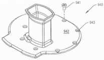
如图62可见的碾磨模块902包括底部外壳904和顶部外壳940,其共同形成该模块的壳体。顶部外壳940被设置于底部外壳902上方。切割盘958和冲击板984被设置于外壳902和940之间。料斗952从顶部外壳940向上延伸。柱塞953可被穿过料斗952推送。汇集托盘980被可拆卸地附接到切割盘958下方的底部外壳904。Themilling module 902 as seen in Figure 62 includes abottom housing 904 and atop housing 940 which together form the housing of the module. Thetop housing 940 is disposed above thebottom housing 902 .Cutting disk 958 andstrike plate 984 are disposed betweenhousings 902 and 940 .Hopper 952 extends upwardly fromtop housing 940 .Plunger 953 may be pushed throughhopper 952 .Collection tray 980 is removably attached tobottom housing 904 below cuttingdisc 958 .

如图63和64中可见,与清洁模块成一体的底部外壳904具有边沿906。边沿906被设定尺寸以座置在环绕组件基部102的顶部延伸的台阶部115。边沿906被形成为具有四个开口908,图中标示出一个开口。外壳904被形成为使得在将清洁模块902座置到组件基部102上时,闩锁组件的凸片548可座置在开口908中以将模块902可释放地保持到基部102。As can be seen in FIGS. 63 and 64 , thebottom housing 904 integral with the cleaning module has arim 906 . Therim 906 is dimensioned to seat on thestep 115 extending around the top of theassembly base 102 . Therim 906 is formed with fouropenings 908, one of which is indicated in the figure.Housing 904 is formed such that when cleaningmodule 902 is seated ontoassembly base 102 ,tab 548 of latch assembly may seat in opening 908 to releasably retainmodule 902 tobase 102 .

底部外壳904被进一步形成为具有平坦的顶表面910。通常为圆形的凹陷表面912位于顶表面910下方。多个膛孔913(图中标示出一个膛孔)从顶表面910向内延伸。膛孔913被环绕凹陷表面912定位且从其径向向外地间隔开。外壳904被形成为使得在凹陷表面912中存在两个开口。第一开口,即开口914,是圆形的,且与凹陷表面912的中心同心。第二开口,即开口918,从凹陷表面912的外周边向内延伸。开口918朝向开口914延伸。环916从凹陷表面912向上延伸且沿周向环绕开口914。环916用作开口914和开口918之间的屏障。外壳904具有第二环,即环920,其也从凹陷表面912向上延伸。环920被紧接凹陷表面912的外周边向内定位。环920并不环绕凹陷表面912沿周向延伸。相反,开口918使环920中断。Bottom housing 904 is further formed to have a flattop surface 910 . A generally circular recessedsurface 912 is located belowtop surface 910 . A plurality of bores 913 (one bore is labeled) extend inwardly fromtop surface 910 . Abore 913 is positioned around and spaced radially outwardly from the recessedsurface 912 .Housing 904 is formed such that there are two openings in recessedsurface 912 . The first opening, opening 914 , is circular and concentric with the center of recessedsurface 912 . A second opening, opening 918 , extends inwardly from the outer perimeter of recessedsurface 912 .Opening 918 extends towardopening 914 . Aring 916 extends upwardly from the recessedsurface 912 and circumferentially surrounds theopening 914 .Ring 916 acts as a barrier betweenopening 914 andopening 918 .Housing 904 has a second ring,ring 920 , which also extends upwardly from recessedsurface 912 .Ring 920 is positioned inwardly adjacent the outer perimeter of recessedsurface 912 .Ring 920 does not extend circumferentially around recessedsurface 912 . Instead, opening 918 interruptsring 920 .

底部外壳904被进一步形成为具有从边沿906向上延伸到顶表面910的多个面板(图中未标示出面板)。侧面板中的一个形成有开口924。开口924向内延伸到外壳中,且被定位成位于开口918下方且与开口918相连。底部外壳904也被成形以使得外壳的形成顶表面910的面板被成形为具有凹口911。凹口911从限定顶表面的面板的限定开口924的部分向内延伸。Bottom housing 904 is further formed with a plurality of panels (panels not labeled) extending upwardly fromrim 906 totop surface 910 . One of the side panels is formed with anopening 924 .Opening 924 extends inwardly into the housing and is positioned below and connected toopening 918 . Thebottom housing 904 is also shaped such that a panel of the housing forming thetop surface 910 is shaped with anotch 911 . Thenotch 911 extends inwardly from the portion of the panel defining the top surface that defines theopening 924 .

套筒926从外壳的凹陷表面912的底侧向下延伸。套筒926限定从开口914向下延伸的贯通膛孔928。底部外壳904被进一步形成为使得多个腹板930从顶表面的底表面向下延伸,且从形成外壳的侧面的面板向内延伸。腹板930为底部外壳提供结构形状。腹板930中的一个限定一个向上延伸的开口932。底部外壳904被成形为使得在碾磨模块902放置于组件基部102上时,膛孔928在主联接器194上居中,且开口932相对于臂联接器486居中。Asleeve 926 extends downwardly from the bottom side of the recessedsurface 912 of the housing.Sleeve 926 defines a throughbore 928 extending downwardly fromopening 914 . Thebottom shell 904 is further formed such that a plurality ofwebs 930 extend downwardly from the bottom surface of the top surface and inwardly from the panels forming the sides of the shell.Web 930 provides structural shape to the bottom shell. One of thewebs 930 defines an upwardly extendingopening 932 .Bottom housing 904 is shaped such that bore 928 is centered onmain coupler 194 andopening 932 is centered relative toarm coupler 486 whenmill module 902 is placed onassembly base 102 .

与碾磨模块902成一体的顶部外壳940(现在参照图65和66描述)具有平坦形状的基部942。外壳的基部942被设定尺寸以座置在底部外壳904的顶表面910上。顶部外壳940被成形为具有被设置于基部942的平坦底面上方的圆形凸起表面944。一组开口943从顶至底地延伸穿过外壳940的限定基部942的部分。开口943被环绕凸起表面944且从其径向向外地定位。碾磨模块902被形成为使得凸起表面944被定位成与凹陷表面同心且具有相同的直径,该凹陷表面与底部外壳的凹陷表面912成一体。每个开口943在底部外壳的膛孔913上方居中。紧固件941(图65中可见一个)延伸穿过每个顶部外壳的开口943进入到下伏(underlying)的底部外壳的膛孔913中。紧固件941因此将顶部外壳940保持到底部外壳904。A top housing 940 (now described with reference to FIGS. 65 and 66 ) integral with themilling module 902 has a base 942 that is flat in shape. Thebase 942 of the housing is dimensioned to seat on thetop surface 910 of thebottom housing 904 . Thetop housing 940 is shaped to have a circular raisedsurface 944 disposed above the flat bottom surface of thebase 942 . A set ofopenings 943 extend from top to bottom through the portion ofhousing 940 definingbase 942 .Opening 943 is positioned around and radially outwardly from raisedsurface 944 . Themilling module 902 is formed such that the raisedsurface 944 is positioned concentric and of the same diameter as the recessed surface that is integral with the recessedsurface 912 of the bottom housing. Eachopening 943 is centered over thebore 913 of the bottom housing. Fasteners 941 (one visible in FIG. 65 ) extend throughopenings 943 of each top shell and intobores 913 of the underlying bottom shell.Fasteners 941 thus holdtop housing 940 tobottom housing 904 .

与凸起表面944同心的两个环从基部942向下延伸。内部环945从表面942毗邻该表面中心向下延伸。外部环946从凸起表面向下延伸且被在凸起表面的外周边稍微向内地定位。更具体地讲,在组装碾磨模块902时,环945被设置在与底部外壳904成一体的环916上。外部环946被设置于下伏的环920上方。Extending downward frombase 942 are two rings concentric with raisedsurface 944 . Aninner ring 945 extends downwardly fromsurface 942 adjacent the center of the surface. Anouter ring 946 extends downwardly from the raised surface and is positioned slightly inwardly of the outer perimeter of the raised surface. More specifically,ring 945 is positioned overring 916 integral tobottom housing 904 when millingmodule 902 is assembled.Outer ring 946 is disposed overunderlying ring 920 .

外壳的基部942被进一步形成为具有凹口943。凹口943是椭圆形状。凹口943被定位成使得在组装模块902时,凹口被在形成于底部外壳的顶表面910中的凹口911紧接上方定位。凹口943并不完全延伸穿过基部942。Thebase 942 of the housing is further formed with anotch 943 . Thenotch 943 is oval in shape. Thenotch 943 is positioned such that when themodule 902 is assembled, the notch is positioned immediately above thenotch 911 formed in thetop surface 910 of the bottom housing. Thenotch 943 does not extend completely through thebase 942 .

顶部外壳940的基部942被进一步形成为具有开口948。开口948通向环944和946之间的凸起表面944的一区段。更具体地讲,顶部外壳的开口948被定位成在底部外壳的开口918上配准。顶部外壳940被进一步形成为使得料斗952从外壳的基部942环绕开口948向上延伸。顶部外壳940的基部942也被形成为具有空腔950,该空腔的边缘在图66中标示出。空腔950从凸起表面944向上延伸。顶部外壳940被形成为使得空腔950与开口948毗邻且相连。Thebase 942 of thetop housing 940 is further formed with anopening 948 . Opening 948 leads to a section of raisedsurface 944 betweenrings 944 and 946 . More specifically, opening 948 of the top housing is positioned to register overopening 918 of the bottom housing. Thetop housing 940 is further formed such that ahopper 952 extends upwardly from thebase 942 of the housing around theopening 948 . Thebase 942 of thetop housing 940 is also formed with acavity 950, the edges of which are indicated in FIG. 66 .Cavity 950 extends upwardly from raisedsurface 944 .Top housing 940 is formed such thatcavity 950 is adjacent to and connected toopening 948 .

图67中最佳可见的切割盘958是圆形形状,且被设定尺寸以放置在底部外壳的凹陷表面912与顶部外壳的凸起表面944之间的空间中。更具体地讲,切割盘958支靠在环916和920上,这些环在凹陷表面912上方延伸。切割盘的直径比该盘座置在其中的空隙空间的直径小大约4mm。切割盘958的厚度比将底部外壳的环916和920与顶部外壳的环945和946分隔开的距离小大约0.25mm。切割盘948因此能够在该盘座置在其中的空隙空间中旋转,以及有限量的从一侧到另一侧移动和有限量的上下移动。Thecutting disc 958, best seen in FIG. 67, is circular in shape and is sized to be placed in the space between theconcave surface 912 of the bottom housing and theconvex surface 944 of the top housing. More specifically, cuttingdisc 958 rests onrings 916 and 920 that extend above recessedsurface 912 . The diameter of the cutting disc is approximately 4mm smaller than the diameter of the void space in which the disc is seated. The thickness of thecutting disk 958 is about 0.25 mm less than the distance separating therings 916 and 920 of the bottom housing from therings 945 and 946 of the top housing. Thecutting disk 948 is thus capable of rotation within the void space in which the disk is seated, as well as a limited amount of side-to-side movement and a limited amount of up-and-down movement.

切割盘958被形成有多个切割元件960,图中标示出一个元件。切割元件960的确切结构并非当前发明的一部分。切割元件的一种结构被公开于以引用方式并入的美国专利公开文献US 2009/0118735/PCT公开文献No.2009/061728中。一般来讲,应当理解,每个切割元件具有一个剪切刃962(图中标示出一个刃)。每个剪切刃962限定切割盘958中的一个开口963的一部分,图中标示出一个开口。切割盘被进一步形成为具有四个等角度间隔开的开口964(图中标示出一个开口)。开口964被从切割元件960径向向内地定位。Cuttingdisc 958 is formed with a plurality of cuttingelements 960, one element being labeled. The exact structure of cuttingelement 960 is not part of the present invention. One configuration of cutting elements is disclosed in US Patent Publication US 2009/0118735/PCT Publication No. 2009/061728, which is incorporated by reference. In general, it should be understood that each cutting element has a cutting edge 962 (one edge is labeled). Eachcutting edge 962 defines a portion of anopening 963 in thecutting disc 958, with one opening indicated. The cutting disk is further formed with four equally angularly spaced openings 964 (one opening is labeled).Opening 964 is positioned radially inward from cuttingelement 960 .

图68和69最佳可见的轴966从切割盘958的中心向下延伸。轴966是大体圆柱形形状。该轴被成形为具有头部970。轴的头部970的直径允许该头部座置在底部外壳904内部的膛孔928中并在其中旋转。圆柱形的杆972在头部970下方延伸。杆972的直径小于头部970的直径。该轴被形成为使得闭端膛孔974从杆972的底部向上延伸。膛孔974在轴966的纵向轴线上居中。膛孔974被设定尺寸以接收与主联接器194成一体的销198。轴966被进一步形成为具有三个等角度间隔开的凹口976,该凹口从膛孔972的基部径向向外地延伸。凹口976并不像膛孔974那样远地向上延伸到轴的杆972中。凹口976被设定尺寸以接收与主联接器194成一体的齿202。Shaft 966 , best seen in FIGS. 68 and 69 , extends downwardly from the center of cuttingdisk 958 .Shaft 966 is generally cylindrical in shape. The shaft is shaped with ahead 970 . The diameter of theshaft head 970 allows the head to seat and rotate within thebore 928 inside thebottom housing 904 . Acylindrical stem 972 extends below thehead 970 . The diameter of thestem 972 is smaller than the diameter of thehead 970 . The shaft is formed such that a closed end bore 974 extends upwardly from the bottom of therod 972 .Bore 974 is centered on the longitudinal axis ofshaft 966 .Bore 974 is sized to receivepin 198 integral withmain coupler 194 . Theshaft 966 is further formed with three equally angularly spacednotches 976 extending radially outward from the base of thebore 972 . Thenotch 976 does not extend as far up into thestem 972 of the shaft as thebore 974 does. Thenotches 976 are sized to receive theteeth 202 integral with themain coupler 194 .

四个销980(图中标示出一个销)从轴的头部970的顶表面向上延伸。销980延伸穿过切割盘958内部的开口964并在其上延伸。销980因此将轴966保持到切割盘958。在组装碾磨模块902时,轴966被设置于底部外壳904内部的膛孔928中。Four pins 980 (one pin labeled) extend upwardly from the top surface of theshaft head 970 .Pin 980 extends through and overopening 964 inside cuttingdisc 958 . Thepin 980 thus holds theshaft 966 to thecutting disc 958 . When millingmodule 902 is assembled,shaft 966 is disposed inbore 928 insidebottom housing 904 .

图62中可见的冲击板984被安装到形成于顶部外壳940中的空腔950中。冲击板984被形成为具有紧接开口948下方的表面。碾磨模块902被设计成使得在致动该模块时,切割盘的剪切刃962朝向冲击板984的上覆表面旋转。Strike plate 984 , visible in FIG. 62 , is mounted intocavity 950 formed intop shell 940 . Theimpingement plate 984 is formed to have a surface immediately below theopening 948 . Themilling module 902 is designed such that upon actuation of the module, thecutting edge 962 of the cutting disc rotates towards the overlying surface of theimpingement plate 984 .

现在参照图70和71描述的汇集托盘988被设定尺寸以可滑动地座置在底部外壳904内部的开口924中。汇集托盘988具有基部990,一组面板992从该基部向上延伸,图中标示出三个面板。唇缘994从最内部的面板992向上延伸,即被最接近于外壳套筒926的面板定位。汇集托盘988被形成为使得在从碾磨模块902的其余部分移除托盘时,该唇缘在切割盘958的被紧接开口918上方定位的区段下方进行清扫。Thecollection tray 988 now described with reference to FIGS. 70 and 71 is sized to be slidably seated within theopening 924 inside thebottom housing 904 . Thecollection tray 988 has a base 990 from which extends upwardly a set ofpanels 992, three of which are indicated. Alip 994 extends upwardly from theinnermost panel 992 , ie is positioned by the panel closest to thehousing sleeve 926 . Thecatch tray 988 is formed such that when the tray is removed from the remainder of themilling module 902 , the lip sweeps under the section of thecutting disc 958 that is positioned immediately above theopening 918 .

手柄996也从最外部的面板992向外突出,即与唇缘994从其延伸的面板间隔开最远的面板。手柄996在与唇缘相关联的面板前方延伸。手柄996用作汇集托盘的由用户抓握以将托盘插入碾磨模块902的其余部分并从碾磨模块902的其余部分移除托盘的部分。Thehandle 996 also projects outwardly from theoutermost panel 992, ie, the panel furthest spaced from the panel from which thelip 994 extends. Ahandle 996 extends forward of the panel associated with the lip. Thehandle 996 serves as the portion of the pooling tray that is grasped by the user to insert the tray into and remove the tray from the remainder of themilling module 902 .

闩998被枢转地安装到手柄996。闩998包括在汇集托盘988的其余部分上方突出的凸片1002。凸片1002被定位成使得在汇集托盘完全座置在开口924中时,该凸片座置在顶部外壳940内部的凹口943中。弹簧1004(图中标示出一个弹簧)将力施加到闩上,正常情况下该力使闩保持锁定状态,即其中凸片1002被设置于凹口943中的状态。闩998的主体上的手指力足以克服由弹簧1004施加的力,以便使闩998枢转。闩998的枢转使凸片1002旋转出凹口943。一旦凸片1002如此旋转,即可从清洁模块902的其余部分移除汇集托盘988。Latch 998 is pivotally mounted to handle 996 . Thelatch 998 includes atab 1002 that protrudes above the remainder of thecollection tray 988 .Tab 1002 is positioned so that when the collection tray is fully seated inopening 924 , it seats innotch 943 insidetop housing 940 . Springs 1004 (one spring is labeled) apply a force to the latch that normally holds the latch in the locked condition, ie the condition in which thetab 1002 is disposed in thenotch 943 . Finger force on the body of thelatch 998 is sufficient to overcome the force exerted by thespring 1004 in order to pivot thelatch 998 . Pivoting of thelatch 998 rotates thetab 1002 out of thenotch 943 . Once thetab 1002 is so rotated, the poolingtray 988 can be removed from the rest of thecleaning module 902 .

磁体1010被安装到汇集托盘988的基部990中。基部990中的其中座置磁体1010的膛孔在图中未标示出。形成本发明的组件100的部件被布置成使得在将汇集托盘988闩锁到清洁模块902中且将清洁模块座置到组件基部102上时,磁体1010位于传感器587上方。Magnets 1010 are mounted into thebase 990 of thecollection tray 988 . The bore in the base 990 in which themagnet 1010 is seated is not labeled in the figure. The components forming theassembly 100 of the present invention are arranged such that themagnet 1010 is located above thesensor 587 when thecollection tray 988 is latched into thecleaning module 902 and the cleaning module is seated onto theassembly base 102 .

V.操作V. Operation

准备使用本发明的组件100的第一步骤是将包括电源595和/或马达控制器596的控制台连接到组件的基部102。如果这些子组件与组件的基部102是分离的,则该步骤是必需的。然后将清洁模块602座置在组件的基部的顶板122上。更具体地讲,将清洁模块602装配到组件的基部,使得作为闩锁组件540的一部分的凸片延伸穿过清洁模块中的槽612。弹簧566在闩锁板542和544以及(延伸而言)闩锁板546上施加足够的力,以将凸片548维持在其向外指向的位置。在凸片548处于向外指向的位置时,闩锁组件540处于闩锁状态。The first step in preparing theassembly 100 of the present invention for use is to connect a console including thepower supply 595 and/ormotor controller 596 to thebase 102 of the assembly. This step is necessary if these subassemblies are separate from thebase 102 of the assembly. Thecleaning module 602 is then seated on thetop plate 122 of the base of the assembly. More specifically, thecleaning module 602 is assembled to the base of the assembly such that the tab that is part of thelatch assembly 540 extends through theslot 612 in the cleaning module.Spring 566 exerts sufficient force onlatch plates 542 and 544 and (by extension)latch plate 546 to maintaintab 548 in its outwardly directed position. With thetab 548 in the outwardly directed position, thelatch assembly 540 is in the latched state.

在将清洁模块602闩锁到组件基部102时,带槽螺杆690的杆692被设置于主联接器194上,如图72可见。如果联接器的齿202并未座置在上覆的槽的凹口702中,则联接器194向下压靠在弹簧212上。限定与板719成一体的凸台712的一部分的凹口718被设置于管联接器348上。如果与管联接器348成一体的齿353并未座置在凹口718中,则管联接器348向下推靠在弹簧394上。驱动销802的杆804被设置于保持架联接器486上。如果与臂联接器486成一体的条状件492并未座置在与驱动销成一体的槽810中,则臂联接器向下推靠在弹簧504上。Upon latching thecleaning module 602 to theassembly base 102, thestem 692 of the slottedscrew 690 is disposed on themain coupler 194, as seen in FIG. 72 . If theteeth 202 of the coupler are not seated in theoverlying slot notches 702 , thecoupler 194 is pressed down against thespring 212 . Anotch 718 defining a portion of aboss 712 integral with a plate 719 is provided on thepipe coupler 348 . If theteeth 353 integral with thepipe coupler 348 are not seated in thenotches 718 , thepipe coupler 348 pushes down against thespring 394 . Therod 804 of thedrive pin 802 is disposed on thecage coupler 486 . If thestrip 492 integral with thearm coupler 486 is not seated in theslot 810 integral with the drive pin, the arm coupler pushes down against thespring 504 .

为将待清洁的骨料放置在模块602中,必须将外壳650提离模块的基部604。为了移除外壳650,将闩880旋转到解锁状态。这将意味着在图1中观看闩880时逆时针旋转该闩。通过凸片886抵靠在榫眼826上的接合实现闩的这一旋转导致产生锁定板818的类似旋转。由于锁定板818的这一旋转,锁定板的凸片822旋转脱离与外壳650成一体的凸片653。这允许从基部604移除外壳。In order to place the aggregate to be cleaned in themodule 602, thehousing 650 must be lifted off thebase 604 of the module. To remove thehousing 650, thelatch 880 is rotated to the unlocked state. This would mean rotating thelatch 880 counterclockwise when viewing the latch in FIG. 1 . This rotation of the latch by the engagement of thetab 886 against themortise 826 results in a similar rotation of thelocking plate 818 . As a result of this rotation of thelocking plate 818 , thetab 822 of the locking plate rotates out of thetab 653 integral with thehousing 650 . This allows the housing to be removed from thebase 604 .

锁定板818的旋转的另一结果是磁体848旋转离开传感器586。在本发明的许多型式中,马达控制器596被配置成允许来自传感器586或587中的单个传感器的信号指示存在接近传感器的磁体时致动马达140。在锁定板818处于解锁位置时,没有磁体毗邻传感器586或传感器587。这意味着按压开关588或590将不会导致马达140的致动。Another result of the rotation of lockingplate 818 is thatmagnet 848 rotates away fromsensor 586 . In many versions of the invention,motor controller 596 is configured to allowmotor 140 to be actuated when a signal from a single one ofsensors 586 or 587 indicates the presence of a magnet proximate to the sensor. No magnets are adjacent eithersensor 586 orsensor 587 when lockingplate 818 is in the unlocked position. This means that pressingswitch 588 or 590 will not result in actuation ofmotor 140 .

同样由于锁定板818的旋转,与锁定板成一体的环形岛状部828旋转,使得环形岛状部的表面829抵靠在驱动销802的趾部898中的一个(如果不是两个的话)上旋转。趾部808的旋转导致驱动销802的类似旋转,以及(延伸而言)臂750和保持架764的枢转。具体地讲,保持架764被定位成图77D中可见的相对于带槽螺杆的取向。由于至少一个趾部808邻靠着环形岛状部的表面829,所以阻碍了驱动销802以及臂750和保持架764的进一步移动。Also due to the rotation of thelocking plate 818, theannular island 828 integral with the locking plate rotates such that thesurface 829 of the annular island abuts on one, if not both, of the toes 898 of thedrive pin 802 rotate. Rotation oftoe 808 causes similar rotation ofdrive pin 802 and (by extension) pivoting ofarm 750 andcage 764 . Specifically,cage 764 is positioned in the orientation seen in FIG. 77D relative to the grooved screw. As at least onetoe 808 abutssurface 829 of the annular island, further movement ofdrive pin 802 andarm 750 andcage 764 is impeded.

在闩880旋转到解锁位置时,闩的进一步旋转被与环形岛状部828成一体的凸片839(邻接止挡件632)的邻接阻挡。在锁定板818如此定位时,肋634座置在凹陷840中以便将锁定板以及(延伸而言)闩880可释放地保持在解锁位置。As thelatch 880 is rotated to the unlocked position, further rotation of the latch is blocked by the abutment of the tab 839 (adjacent to the stop 632 ) integral with theannular island 828 . With the lockingplate 818 so positioned, therib 634 seats in therecess 840 to releasably retain the locking plate and, by extension, thelatch 880 in the unlocked position.

待清洁和碾磨的骨料随后被放置到保持架764内部的空隙空间765中。外壳650被座置回模块基部604上。由于外壳在基部604上的座置,与毂状件860成一体的销的足部878座置在带槽螺杆690内部的孔704中。闩880旋转到图1所示的位置,以便将外壳返回到锁定状态。由于闩的这种旋转,锁定板818被旋转到锁定状态。锁定板818被旋转以使得锁定板的凸片822座置在与外壳604成一体的凸片653上。这种凸片在凸片上的配准正是将外壳650可释放地锁定到基部604。The aggregate to be cleaned and ground is then placed into thevoid space 765 inside thecage 764 . Thehousing 650 is seated back on themodule base 604 . Due to the seating of the housing on thebase 604 , thefoot 878 of the pin integral to the hub 860 is seated in thebore 704 inside the slottedscrew 690 .Latch 880 is rotated to the position shown in FIG. 1 to return the housing to the locked state. Due to this rotation of the latch, the lockingplate 818 is rotated into the locked state. The lockingplate 818 is rotated so that thetab 822 of the locking plate seats on thetab 653 integral with thehousing 604 . It is this tab-on-tab registration that releasably locks thehousing 650 to thebase 604 .

由于锁定板818的旋转,锁定板的环形岛状部828呈现如图74中可见的相对于与驱动销802成一体的趾部808的取向。更具体地讲,环形岛状部828远离趾部808间隔开。这意味着驱动销和(延伸而言)臂750和保持架764可自由旋转。As a result of the rotation of thelocking plate 818 , theannular island 828 of the locking plate assumes an orientation relative to thetoe 808 integral with thedrive pin 802 as can be seen in FIG. 74 . More specifically,annular island 828 is spaced away fromtoe 808 . This means that the drive pin and (by extension) thearm 750 andcage 764 are free to rotate.

在闩880旋转到锁定位置时,闩的进一步旋转被与环形岛状部828成一体的凸片839(邻接止动件638)的邻接阻挡。在锁定板818这样定位时,肋636座置在凹陷840中以便将锁定板和(延伸而言)闩锁880可释放地保持在锁定位置。As thelatch 880 is rotated into the locked position, further rotation of the latch is blocked by the abutment of the tab 839 (adjacent to the stop 638 ) integral with theannular island 828 . With the lockingplate 818 so positioned, therib 636 seats in therecess 840 to releasably retain the locking plate and (by extension) thelatch 880 in the locked position.

将锁定板818旋转到锁定位置还导致磁体848的旋转,使得磁体在传感器586上旋转。传感器586随之将指示磁体出现在传感器面前的信号输出到马达控制器596。马达控制器586将此信号解译为指示组件100处于其中清洁模块602被附接到基部且模块外壳650被锁定到模块基部604的状态下。在马达控制器596确定组件100处于这种状态下时,控制器致动LED 588,即毗邻开关586的LED。这提供了视觉指示:需要按压以致动组件的开关是开关586,即用于开始清洁过程的开关。Rotating the lockingplate 818 to the locked position also causes rotation of themagnet 848 causing the magnet to rotate on thesensor 586 . Thesensor 586 then outputs a signal to themotor controller 596 indicative of the presence of a magnet in front of the sensor. Themotor controller 586 interprets this signal as indicating that theassembly 100 is in a state in which thecleaning module 602 is attached to the base and themodule housing 650 is locked to themodule base 604 . Whenmotor controller 596 determines thatassembly 100 is in this state, the controller actuatesLED 588 , the LED adjacent to switch 586 . This provides a visual indication that the switch that needs to be pressed to activate the component isswitch 586, the switch used to start the cleaning process.

一旦按下开关586,马达控制器596即致动马达140持续一段时间。通常,此段时间介于3分钟与20分钟之间。如下文论述的,马达140的致动导致三个联接器194、348和486的类似旋转移动。在旋转主联接器194时,弹簧214将联接器的齿202推入上覆的带槽螺杆690的凹口702中。带槽螺杆690因此与主联接器194一致地旋转。弹簧394向上推管联接器348,使得联接器的齿353座置在与翻转板710相关联的凹口718中。这种齿在槽中的接合致使翻转板和剃刮管与管联接器一起旋转。弹簧504致使旋转的保持架联接器的条状件492座置在与驱动销802成一体的槽810中。驱动销因此将保持架联接器的旋转运动传递到臂750和保持架764。Onceswitch 586 is pressed,motor controller 596 actuatesmotor 140 for a period of time. Typically, this period of time is between 3 minutes and 20 minutes. As discussed below, actuation of themotor 140 results in similar rotational movement of the threecouplers 194 , 348 and 486 . As themain coupler 194 is rotated, the spring 214 pushes the coupler'steeth 202 into thenotches 702 of the overlyinggrooved screw 690 . The slottedscrew 690 thus rotates in unison with themain coupler 194 . Thespring 394 pushes thetube coupler 348 upward so that the coupler'steeth 353 seat in thenotches 718 associated with theflip plate 710 . Engagement of this tooth in the slot causes the flip plate and shaving tube to rotate with the tube coupler. Thespring 504 causes thebar 492 of the rotating cage coupler to seat in theslot 810 integral with thedrive pin 802 . The drive pin thus transmits the rotational movement of the cage coupler to thearm 750 andcage 764 .

实际的骨清洁过程由多个清洁周期构成。每个周期由一组阶段构成。在本发明的这种型式中,马达140通过传动机构144和心轴170使主联接器194持续地旋转。连接到主联接器194的带槽螺杆690与主联接器一起旋转。即使在下述的一些阶段中,其中螺杆的旋转可能对骨清洁过程没有帮助,带槽螺杆690仍然旋转。The actual bone cleansing process consists of multiple cleansing cycles. Each cycle consists of a set of phases. In this version of the invention, themotor 140 continuously rotates themain coupling 194 through thetransmission 144 and thespindle 170 . A slottedscrew 690 connected to themain coupler 194 rotates with the main coupler. The slottedscrew 690 rotates even during the phases described below where the rotation of the screw may not be helpful to the bone cleaning process.

心轴170的旋转移动通过传动机构220被传递到臂凸轮234和离合器凸轮252。在从图75中呈现的凸轮视图观看时,臂凸轮234以逆时针方向旋转。在从图76中呈现的凸轮视图观看时,离合器凸轮252也以逆时针方向旋转。The rotational movement of thespindle 170 is transmitted to thearm cam 234 and theclutch cam 252 through thetransmission mechanism 220 . Thearm cam 234 rotates in a counterclockwise direction when viewed from the cam view presented in FIG. 75 . Theclutch cam 252 also rotates in a counterclockwise direction when viewed from the cam view presented in FIG. 76 .

清洁周期的第一阶段是按压阶段。在按压阶段,离合器凸轮252的内凸部258骑靠在棘爪396上。在图76中,棘爪396的辊412由三角形来代表。这意味着离合器处于脱离状态。翻转板710和剃刮管724因此并不旋转。同时,臂凸轮的外凸部238可靠在摇杆臂508上旋转。在图75中,摇杆臂508的抵靠在臂凸轮234上的辊524由圆形来表示。因此,摇杆臂508和曲柄448协作以将轴422保持为具体的旋转取向。这种具体的旋转取向,正如图77A所表示的取向,是其中保持架被定位成使得压块772指向剃刮管724内部的窗口728的取向。The first phase of the cleaning cycle is the pressing phase. During the depressing phase, theinner protrusion 258 of theclutch cam 252 rides against thepawl 396 . In FIG. 76, theroller 412 of thepawl 396 is represented by a triangle. This means the clutch is disengaged. Theflip plate 710 and theshaving tube 724 therefore do not rotate. Simultaneously, thelobes 238 of the arm cams may rotate on therocker arms 508 . In FIG. 75, theroller 524 of therocker arm 508 which rests on thearm cam 234 is represented by a circle. Thus,rocker arm 508 and crank 448 cooperate to maintainshaft 422 in a particular rotational orientation. This particular rotational orientation, such as that shown in FIG. 77A , is the orientation in which the cage is positioned such that theweight 772 points toward thewindow 728 inside the shavingtube 724 .

由于清洁模块602已经历了前一周期的下述清扫阶段,被清洁的骨碎片此前已被收集在毗邻压块772的保持架的空隙空间765中。如下文论述,压块772被定位成被相对接近剃刮管窗口728定位。这种压块靠近带槽螺杆和剃刮管的定位的益处是,这增加了使骨料压靠在带槽螺杆690上的可能性。这意味着在清洁模块602处于按压阶段中时,压块772对骨料按压使其穿过管窗口728而抵靠在旋转的带槽螺杆690上。附接到骨料的软组织被夹带到各个旋转的槽694中。旋转的槽694逆着剃刮管724的切刃726牵拉软组织。这种组织逆着剃刮管的移动从骨上切下组织。更具体地讲,带槽螺杆的旋转切刃696逆着剃刮管的静态切刃的移动将软组织从骨料上切下。As thecleaning module 602 has undergone the sweeping phase of the previous cycle described below, cleaned bone fragments have previously been collected in thevoid space 765 of the cage adjacent the compact 772 . As discussed below, thepressure block 772 is positioned so as to be positioned relatively proximate to the shavingtube window 728 . A benefit of this positioning of the pressure block close to the grooved screw and shaving tube is that it increases the likelihood of the aggregate being pressed against thegrooved screw 690 . This means that when thecleaning module 602 is in the pressing phase, the pressure block 772 presses the aggregate through thetube window 728 against the rotatinggrooved screw 690 . Soft tissue attached to the aggregate is entrained into eachrotating slot 694 . Therotating flute 694 pulls soft tissue against thecutting edge 726 of the shavingtube 724 . This tissue cuts tissue from the bone against the movement of the shaving tube. More specifically, therotating cutting edge 696 of the grooved screw cuts the soft tissue away from the aggregate against the movement of the static cutting edge of the shaving tube.

在清洁模块602经历单独的按压阶段之前,不可能知道将要由压块772抵靠在带槽螺杆690上按压的一块或多块骨料的尺寸和形状。为了确保压块772使各种尺寸和形状的骨料压靠在带槽螺杆690上,将要求保持架驱动器420的帽盖464能够相对于轴422以有限的旋转度接合。弹簧534使帽盖464环绕轴422保持在具体的旋转取向中。更具体地讲,弹簧534将轴保持在一取向中,使得如果不存在抵靠在压块772上的骨料,则帽盖464、臂联接器486、驱动销802和臂750协作以保持住保持架764,使得压块772远离剃刮管窗口728间隔开一段短的距离。在本发明的多数型式中,清洁模块被构造成使得如果不存在毗邻压块的骨料,则当清洁周期处于按压阶段中时,压块和剃刮管724的外表面之间的最大距离是8mm。更理想地,在不存在骨料时压块和剃刮管724之间的最大距离是4mm。It is not possible to know the size and shape of the piece or pieces of aggregate that will be pressed against thegrooved screw 690 by thepressing block 772 until thecleaning module 602 goes through a separate pressing phase. To ensure that thepress block 772 presses aggregates of various sizes and shapes against the slottedscrew 690 would require that thecap 464 of thecage driver 420 be able to engage in a limited degree of rotation relative to theshaft 422 .Spring 534 maintainscap 464 in a particular rotational orientation aboutaxis 422 . More specifically, thespring 534 holds the shaft in an orientation such that if there is no aggregate against thepressure block 772, thecap 464,arm coupler 486,drive pin 802, andarm 750 cooperate to holdHolder 764 such thatpressure block 772 is spaced a short distance away from shavingtube window 728 . In most versions of the invention, the cleaning module is configured such that if there is no aggregate adjacent to the compact, when the cleaning cycle is in the pressing phase, the maximum distance between the compact and the outer surface of the shavingtube 724 is 8mm. More desirably, the maximum distance between the compact and theshaving tube 724 in the absence of aggregate is 4mm.

当骨料被夹在压块772和剃刮管724之间时,轴422和保持架764之间的间隙意味着保持架的移动不会导致产生迫使压块进入到其密切接近带槽螺杆690的位置的强硬的力。而是,弹簧534将力矩施加到帽盖464上,致使相关联的部件依次将力施加到保持架764上。该力施加在保持架上,以使得压块772推动骨料穿过剃刮管窗口728并进入到旋转的槽694中。在本发明的一些型式中,组件的基部102被构造成使得力弹簧534致使保持架764将介于8和40牛顿之间的力施加在困在压块772和带槽螺杆690之间的骨料上。When the aggregate is clamped between thebriquetting block 772 and theshaving tube 724, the clearance between theshaft 422 and thecage 764 means that movement of the cage does not cause the briquetting block to be forced into its close proximity to thegrooved screw 690. The strong force of the position. Instead, thespring 534 applies a moment to thecap 464 causing the associated components to in turn apply a force to thecage 764 . This force is exerted on the cage such that theweight 772 pushes the aggregate through the shavingtube window 728 and into therotating slot 694 . In some versions of the invention, thebase 102 of the assembly is configured such that theforce spring 534 causes thecage 764 to apply a force of between 8 and 40 Newtons to the bone trapped between thecompression block 772 and thegrooved screw 690. material.

在按压阶段期间,带槽螺杆690经受侧面负载。静态销874存在于螺杆690内部的膛孔704中避免了这种侧面负载使带槽螺杆690偏转到使槽694开始刮擦剃刮管724的内表面的位置。During the compression phase, the slottedscrew 690 is subjected to side loading. The presence of thestatic pin 874 in thebore 704 inside thescrew 690 prevents such side loading from deflecting thegrooved screw 690 to a position where thegroove 694 begins to scrape the inner surface of the shavingtube 724 .

按压阶段之后是翻转阶段。该组件由于离合器凸轮252旋转使得凸轮的外凸部262靠在棘爪396上旋转而从按压阶段过渡到翻转阶段。因此而发生的棘爪远离凸片304的枢转使离合器切换到接合状态。翻转板710和剃刮管724因此与带槽螺杆690同时且沿同一方向以相同速度旋转。臂凸轮234的外凸部238继续靠在摇杆臂508上旋转。因此,在模块经过按压阶段过渡时,保持架相对于剃刮管保持在同一位置。The compression phase is followed by an inversion phase. The assembly transitions from the depressing phase to the flipping phase as theclutch cam 252 rotates causing theouter lobe 262 of the cam to rotate against thepawl 396 . The resulting pivoting of the pawl away from thetab 304 shifts the clutch into the engaged state. Theflip plate 710 and theshaving tube 724 thus rotate at the same speed at the same time and in the same direction as the slottedscrew 690 . Thecam 238 of thearm cam 234 continues to rotate against therocker arm 508 . Thus, the holder remains in the same position relative to the shaving tube when the module transitions through the pressing phase.

由于剃刮管724的旋转,该管使设置于管窗口中的骨料沿图77B的图示中的逆时针方向旋转。这将骨料清除出剃刮管724与压块772之间的空间。As a result of the rotation of the shavingtube 724, the tube rotates the aggregate disposed in the tube window in a counterclockwise direction in the illustration of Figure 77B. This clears aggregate out of the space between the shavingtube 724 and the compact 772 .

在翻转阶段期间,翻转板710的旋转可辅助骨的翻转。During the inversion phase, rotation of theinversion plate 710 may assist in inversion of the bone.

切换阶段跟在翻转阶段之后。过渡到切换阶段发生在外凸部238与内凸部242之间的臂凸轮234的线性表面靠在摇杆臂508上旋转时。由此产生的摇杆臂508的枢转致使保持架驱动器420使保持架764枢转,使得压块772远离带槽螺杆690移动且肋780朝向带槽螺杆移动,如图77C中可见。The switching phase follows the flipping phase. The transition to the switching phase occurs when the linear surface of thearm cam 234 between theouter lobes 238 and theinner lobes 242 rotates against therocker arm 508 . The resulting pivoting ofrocker arm 508 causescage driver 420 to pivotcage 764 such that pressure block 772 moves away from slottedscrew 690 andrib 780 moves toward the slotted screw, as seen in FIG. 77C .

在切换阶段期间,离合器凸轮252的外凸部262继续骑靠在棘爪396上。翻转板710和剃刮管724继续旋转。清洁模块的这些部件在切换阶段的旋转可能并不明显地有助于骨的清洁。During the shift phase, theouter lobes 262 of theclutch cam 252 continue to ride against thepawls 396 . The turningplate 710 and theshaving tube 724 continue to rotate. Rotation of these parts of the cleaning module during the switching phase may not significantly contribute to bone cleaning.

如图77C所示,在清洁过程期间,一块骨料可能被卡在相对快速旋转的带槽螺杆与较慢旋转的剃刮管724之间。这种情况的出现是由于软组织的尾部可能被拉入管的窗口728中并缠绕在带槽螺杆690周围。如果组织并未卡在槽694上,则该组织可能并未利用致使组织被切断所需的力而压抵切刃726。As shown in FIG. 77C , during the cleaning process, a piece of aggregate may become lodged between the relatively fast rotating fluted screw and the slowerrotating shaving tube 724 . This occurs because the tail of soft tissue may be pulled into thewindow 728 of the tube and wrap around the slottedscrew 690 . If the tissue is not caught on theslot 694, the tissue may not be pressing against thecutting edge 726 with the force required to cause the tissue to be severed.

一旦臂凸轮234的旋转导致凸轮的内凸部242骑靠在摇杆臂508上,则本发明的组件进入清除和收集阶段。在清除和收集阶段,离合器凸轮252的外凸部226继续骑靠在棘爪396上。Once the rotation of thearm cam 234 causes the cam'sinner lobe 242 to ride against therocker arm 508, the assembly of the present invention enters the purge and collect phase. During the purge and collect phases, thelobes 226 of theclutch cam 252 continue to ride on thepawls 396 .

因此,在清除和收集阶段,肋780与带槽螺杆和剃刮管紧密接近。带槽螺杆、翻转板和剃刮管继续旋转。由于翻转板的旋转,骨料朝向保持架面板770的内表面旋转,如图77D可见。肋780因此用作清洁模块的利于将困住的骨料从清洁组件、带槽螺杆和剃刮管清除出去的部件。Thus, theribs 780 are in close proximity to the grooved screw and shaving tube during the removal and collection phases. The slotted screw, flip plate and shaving tube continue to rotate. Due to the rotation of the flip plate, the aggregate rotates towards the inner surface of thecage panel 770, as seen in Figure 77D. Theribs 780 thus serve as components of the cleaning module that facilitate the removal of trapped aggregate from the cleaning assembly, grooved screw and shaving tube.

由于剃刮管的旋转,卡在带槽螺杆和剃刮管之间的骨料靠在肋780上旋转。更常见地,骨料靠在表面782上旋转。骨料沿着表面782向下行进。随着骨向下移动,组织的尾部被压靠在旋转的剃刮管724的切刃上。这种切刃抵靠组织的动作的结果是组织被从骨料切离。骨料因此被从带槽螺杆690释放出来。Due to the rotation of the shaving tube, the aggregate caught between the grooved screw and the shaving tube rotates against theribs 780 . More generally, the aggregate rotates againstsurface 782 . The aggregate travels down thesurface 782 . As the bone moves down, the tail of the tissue is pressed against the cutting edge of therotating shaving tube 724 . As a result of this action of the cutting edge against the tissue, the tissue is severed from the aggregate. Aggregate is thus released from thegrooved screw 690 .

单个清洁周期的最后一个阶段是清扫阶段。由于离合器凸轮252的旋转,凸轮的内凸部靠在棘爪396上旋转。随后迫使凸片304回抵在棘爪396上。这使得离合器278返回到脱离状态。翻转板710和剃刮管724因此停止旋转。更具体地讲,在这种情况发生时,剃刮管724需要在接下来的按压阶段中使压块朝向窗口728。The final phase of a single cleaning cycle is the sweep phase. As theclutch cam 252 rotates, the inner lobe of the cam rotates against thepawl 396 .Tab 304 is then forced back againstdetent 396 . This returns clutch 278 to the disengaged state. Theflip plate 710 and shavingtube 724 thus stop rotating. More specifically, when this happens, the shavingtube 724 needs to orient the pressure block toward thewindow 728 during the next pressing phase.

同样在清扫阶段,由于臂凸轮234的旋转,内凸部242和外凸部238之间的凸轮过渡表面靠在摇杆臂508上旋转。保持架驱动器420因此使保持架764枢转,如图77E所示的,使得压块772再次被回定位到在按压阶段中时的位置,如图77A所表示的。由于保持架764的这种运动,保持架将抵靠在面板770上的骨料推到抵靠剃刮管的窗口728。因此,在清扫阶段结束时,骨料再次被压块772按压而抵靠在剃刮管的窗口上。Also during the sweeping phase, the cam transition surface between theinner lobe 242 andouter lobe 238 rotates against therocker arm 508 due to the rotation of thearm cam 234 . Thecage driver 420 thus pivots thecage 764, as shown in Figure 77E, so that thepressure block 772 is again positioned back to the position it was in the compression phase, as shown in Figure 77A. Due to this movement of theretainer 764, the retainer pushes the aggregate against thepanel 770 against thewindow 728 of the shaving tube. Thus, at the end of the sweeping phase, the aggregate is again pressed by the pressure block 772 against the window of the shaving tube.

清扫阶段的完成结束了清洁模块的部件经过单个清洁周期的移动。该组件随后致使清洁模块前进经过后续清洁周期的按压阶段。Completion of the sweeping phase ends the movement of the components of the cleaning module through a single cleaning cycle. The assembly then causes the cleaning module to advance through the pressing phase of the subsequent cleaning cycle.

在本发明的一些型式中,单个清洁周期持续3到20秒之间。按压阶段持续该周期的25%到50%之间。理想地,在单个按压阶段期间,带槽螺杆应当进行至少四个360°的旋转,否则应进行至少六个旋转。翻转阶段占据单个清洁周期的10%与40%之间。在单个翻转阶段中,剃刮管应当进行至少两个完整旋转,否则应进行三个或更多个完整旋转。清除和收集阶段通常占据单个清洁周期的5%和20%之间。切换和清扫阶段各自占据单个清洁周期的5%和15%之间。在本发明的一些型式中,一旦致动该组件以清洁骨料,则该组件即保持致动持续介于3分钟与20分钟之间的时间段。通常组件100被致动持续介于5分钟与20分钟之间的时间段。在本发明的许多型式中,该组件被致动持续介于8分钟与15分钟之间的时间段。In some versions of the invention, a single cleaning cycle lasts between 3 and 20 seconds. The compression phase lasts between 25% and 50% of the cycle. Ideally, the grooved screw should make at least four 360° rotations, otherwise at least six rotations, during a single compression phase. The tumble phase occupies between 10% and 40% of a single cleaning cycle. In a single turning phase, the shaving tube should make at least two full revolutions, otherwise three or more full revolutions. The purge and collect phases typically occupy between 5% and 20% of a single cleaning cycle. The switching and sweeping phases each occupy between 5% and 15% of a single cleaning cycle. In some versions of the invention, once the assembly is activated to clean the aggregate, the assembly remains activated for a period of between 3 minutes and 20 minutes. Typicallyassembly 100 is activated for a period of time between 5 and 20 minutes. In many versions of the invention, the assembly is activated for a period of time between 8 and 15 minutes.

在马达控制器596使马达140停止活动后,从基部移除清洁模块602。这一活动是通过将闩锁组件540移动到解锁状态来实现的。这是通过将指握件562朝向彼此按下来实现的。应当理解,手指的力足以克服弹簧566施加在板542和544上以将闩锁组件保持在闩锁状态下的力。指握件的移动导致板542和544的类似移动。板542和546的移动使板546和凸片548向内枢转。凸片548的枢转移动使凸片从槽612撤回,以便将闩锁组件540置于解锁状态。此时,清洁模块602可从组件基部102移除。After themotor controller 596 deactivates themotor 140, thecleaning module 602 is removed from the base. This activity is accomplished by moving thelatch assembly 540 to the unlocked state. This is accomplished by pressing thefingergrips 562 toward each other. It should be appreciated that finger force is sufficient to overcome the force exerted byspring 566 onplates 542 and 544 to maintain the latch assembly in the latched condition. Movement of the finger grip results in similar movement ofplates 542 and 544 . Movement ofplates 542 and 546pivots plates 546 andtabs 548 inwardly. Pivotal movement of thetab 548 withdraws the tab from theslot 612 to place thelatch assembly 540 in the unlocked state. At this point, thecleaning module 602 may be removed from theassembly base 102 .

碾磨模块902随后被座置在组件基部102上。闩锁组件540被用于以与组件540被用于将清洁模块602保持就位的方式相同的方式将碾磨模块902保持到组件的基部102。闩锁组件的凸片548延伸穿过碾磨模块902的底部外壳904中的开口908。在将碾磨模块如此固定到组件基部102时,组件的杆966的底侧被设置于主联接器上方。在最低限度,联接器的销198座置在杆的膛孔974中。套筒926的底端被设置于管联接器348上。臂联接器486座置于底部外壳的底侧中的开口932中,如图78中可见。Themilling module 902 is then seated on theassembly base 102 . Thelatch assembly 540 is used to hold themilling module 902 to thebase 102 of the assembly in the same manner that theassembly 540 is used to hold thecleaning module 602 in place. Thetab 548 of the latch assembly extends through anopening 908 in thebottom housing 904 of themilling module 902 . With the milling module thus secured to theassembly base 102, the underside of the assembly'sstem 966 is positioned above the main coupler. At a minimum, thepin 198 of the coupler is seated in thebore 974 of the rod. The bottom end of thesleeve 926 is positioned over thepipe coupler 348 .Arm coupler 486 seats in opening 932 in the bottom side of the bottom housing, as seen in FIG. 78 .

被清洁的骨料随后传送到磨骨机的料斗952。此过程以外壳660从清洁模块602的其他部分的解锁开始。由于闩880的旋转,锁定圆盘818返回到图73的旋转位置。锁定圆盘的移动导致驱动销802的枢转。驱动销的枢转导致臂750和保持架764的类似枢转。保持架764枢转到如图77D中可见的取向。在这里,保持架764被定位成使得压块被更接近翻转板710的周边定位,且远离带槽螺杆690间隔开。The cleaned aggregate is then conveyed to thehopper 952 of the bone grinder. The process begins with the unlocking of thehousing 660 from the rest of thecleaning module 602 . Due to the rotation of thelatch 880, thelocking disc 818 returns to the rotated position of FIG. 73 . Movement of the locking puck causes pivoting of thedrive pin 802 . Pivoting of the drive pin results in similar pivoting ofarm 750 andcage 764 .Cage 764 pivots to the orientation as seen in Figure 77D. Here, theretainer 764 is positioned such that the pressure blocks are positioned closer to the perimeter of theflip plate 710 and spaced away from the slottedscrew 690 .

在保持架764处于这种取向时,清洁模块902被带到料斗952的开口端,且保持架的毗邻凸片792的端部朝向料斗。借助重力的辅助,被清洁的骨料随后被传送到料斗952中。一旦传送完成,柱塞953被置于料斗中。Withholder 764 in this orientation,cleaning module 902 is brought to the open end ofhopper 952 with the end of the holderadjacent tab 792 facing the hopper. The cleaned aggregate is then conveyed into ahopper 952 with the aid of gravity. Once the transfer is complete, theplunger 953 is placed in the hopper.

在将碾磨模块902座置于组件基部的顶板122上,且将汇集托盘980闩锁到模块开口924中时,磁体1010被设置于传感器587上。传感器587因此将指示感测到该磁场的信号输出到马达控制器596。马达控制器596将该信号的存在解译为指示包括汇集托盘990的碾磨模块902处于对待进行的碾磨过程来说恰当的位置。马达控制器随后致动与开关590相关联的LED 591。When themilling module 902 is seated on thetop plate 122 of the assembly base, and thecollection tray 980 is latched into themodule opening 924 , themagnet 1010 is positioned on thesensor 587 . Thesensor 587 thus outputs a signal to themotor controller 596 indicative of sensing the magnetic field. Themotor controller 596 interprets the presence of this signal as an indication that themilling module 902, including thecollection tray 990, is in the proper position for the milling process to be performed. The motor controller then actuates theLED 591 associated with theswitch 590 .

为了磨骨,压下开关590。在将组件100如此配置以磨骨时,只要压下开关590,马达控制器596就致动马达。由此产生的主联接器194的旋转导致切割盘958的旋转。在切割盘958旋转时,执行碾磨过程的人员在柱塞953上向下按压。骨料被推靠在旋转的切割盘上。切割元件使骨料抵靠在冲击板984上,从而导致骨料被剪切成骨碎片。骨碎片经过切割盘中的开口963落到汇集托盘988中。To grind the bone,switch 590 is depressed. Withassembly 100 so configured for bone grinding,motor controller 596 activates the motor wheneverswitch 590 is depressed. The resulting rotation ofmaster coupler 194 results in rotation of cuttingdisc 958 . The person performing the milling process presses down on theplunger 953 as thecutting disc 958 rotates. Aggregate is pushed against the rotating cutting disc. The cutting elements force the aggregate against theimpact plate 984, causing the aggregate to be sheared into bone fragments. The bone fragments fall through theopening 963 in the cutting disc into thecollection tray 988 .

在碾磨过程完成时,从碾磨模块902移除汇集托盘988。骨碎片可用于其中需要使用骨碎片的手术中。Upon completion of the milling process, poolingtray 988 is removed from millingmodule 902 . The bone fragments may be used in procedures where the use of bone fragments is required.

由于从碾磨模块902移除了汇集托盘988,磁体1010被从互补的传感器587撤离。传感器587因此不再坚持传递给马达控制器596的信号,该信号表示具有被闩锁的汇集托盘988的碾磨模块902被附接到组件基部102。由于来自传感器587的信号的改变,马达控制器596不再在压下开关590时致动马达140。As the poolingtray 988 is removed from themilling module 902 , themagnet 1010 is withdrawn from thecomplementary sensor 587 . Thesensor 587 therefore no longer maintains a signal to themotor controller 596 indicating that themilling module 902 with thecatch tray 988 being latched is attached to theassembly base 102 . Due to the change in signal fromsensor 587,motor controller 596 no longer actuatesmotor 140 whenswitch 590 is depressed.

本发明的组件100因此提供了一种装置,该装置首先清洁且然后碾磨新鲜获取的骨料,其仅需要与骨料有最小程度的人员接触。骨清洁模块602被设计成用以移除通常附着到骨料的软组织。模块602被设计成使得,如果在清洁过程期间,骨料被卡在带槽螺杆和剃刮管之间,则该模块的部件协作以将骨料从这些部件上剪切下。骨清洁模块602被进一步配置成在清洁通常发生的按压阶段之间,使骨料翻转。这明显地增加了每一块骨料的暴露表面将压靠在带槽螺杆和剃刮管上的可能性。增加每一块骨料如此定位的可能性导致每一块骨料的彻底清洁的可能性类似增加。Theassembly 100 of the present invention thus provides a device that first cleans and then grinds freshly harvested aggregate that requires only minimal human contact with the aggregate. Thebone cleaning module 602 is designed to remove soft tissue that is usually attached to the bone material.Module 602 is designed so that, if aggregate becomes lodged between the grooved screw and the shaving tube during the cleaning process, the components of the module cooperate to shear the aggregate from these components. Thebone cleaning module 602 is further configured to flip the aggregate between pressing phases where cleaning typically occurs. This significantly increases the likelihood that the exposed surface of each aggregate will be pressed against the grooved screw and scraper tube. Increasing the likelihood of each aggregate being so positioned results in a similarly increased likelihood of thorough cleaning of each aggregate.

为了确保骨料被这样清洁,保持架中的凹陷769的存在为保持架提供了空隙空间765,使得毗邻压块772存在显著的空间。毗邻压块的大量空间的优势有利于在翻转阶段期间使骨远离带槽螺杆和剃刮管而移开。然后,在清扫阶段,凹陷769的存在意味着保持架的面板768和770之间的距离小于不存在凹陷769的情况下应有的距离。这意味着翻转的骨被容纳在较小空间中。这提高了在清扫阶段期间骨被收集并朝向带槽螺杆指向以便用于下一按压阶段的程度。To ensure that the aggregate is so cleaned, the presence ofrecesses 769 in the cage provides avoid space 765 for the cage such that there is significant space adjacent to the compact 772 . The advantage of the large amount of space adjacent to the pressure block facilitates moving the bone away from the grooved screw and shaving tube during the inversion phase. Then, during the sweeping phase, the presence of therecess 769 means that the distance between thepanels 768 and 770 of the cage is smaller than it would be if therecess 769 were not present. This means that the flipped bone is accommodated in less space. This increases the degree to which bone is collected during the clearing phase and directed towards the slotted screw for the next compression phase.

本发明的清洁模块的另一特征是从骨上切除的组织被螺旋输送到与模块外壳650相关联的汇集空间682中。这意味着执行清洁过程的人员不必关注此废料的收集和处置。Another feature of the cleaning module of the present invention is that the tissue excised from the bone is helically delivered into thecollection volume 682 associated with themodule housing 650 . This means that those performing the cleaning process do not have to be concerned with the collection and disposal of this waste.

本发明的骨清洁模块602被进一步设计成使得在清洁过程之后,在移除外壳650时,将保持架保持在相对于带槽螺杆690和剃刮管724的具体位置。更具体地讲,保持架764被定位成使得有利于将经过清洁的骨料借助重力传送到碾磨模块902中。Thebone cleaning module 602 of the present invention is further designed such that the retainer is held in a specific position relative to the slottedscrew 690 and shavingtube 724 when thehousing 650 is removed after the cleaning process. More specifically,cage 764 is positioned so as to facilitate gravity transfer of cleaned aggregate intomilling module 902 .

VI.替代性清洁模块特征VI. Alternative Cleaning Module Characteristics

图86示出了本发明的替代性清洁模块1250的内侧特征。模块1250包括与清洁模块602相同的许多基本部件。因此,不再重复描述这些部件。两个模块之间的一个差异是臂的结构。模块1250包括臂1252和保持架1254。臂1252的形状和功能与臂750大致相同。保持架1254从臂1250延伸。两个组件之间的差异是,在图54和图86的组件的对比中,保持架764向外延伸到臂750的右侧;保持架1254延伸到臂1252的左侧。保持架1254包括面板1255、1256和1257。面板1255、1256和1257分别与保持架764的面板766、768和770类似。在面板1256和1257相交处形成的拐角之间的压块在图中不可见。Figure 86 shows the inside features of analternative cleaning module 1250 of the present invention.Module 1250 includes many of the same basic components as cleaningmodule 602 . Therefore, description of these components will not be repeated. One difference between the two modules is the structure of the arms.Module 1250 includes anarm 1252 and a holder 1254 .Arm 1252 is substantially the same in shape and function asarm 750 . A cage 1254 extends from thearm 1250 . The difference between the two assemblies is that, in a comparison of the assemblies of FIG. 54 and FIG. 86 ,cage 764 extends out to the right ofarm 750 ; cage 1254 extends to the left ofarm 1252 . Cage 1254 includespanels 1255 , 1256 and 1257 .Panels 1255, 1256, and 1257 are similar topanels 766, 768, and 770 ofcage 764, respectively. The compression blocks between the corners formed wherepanels 1256 and 1257 meet are not visible in the figure.

保持架1254被进一步形成为具有斜坡1258。斜坡1258从面板1255向内突出。斜坡1258包括与肋780的表面782类似的倾斜表面1259,图中未标示出斜坡表面。表面1259从面板1255向上延伸到面板1255与1257之间的拐角。模块1252包括保持架1254。随着肋1258向上延伸,横跨肋的基部的宽度减小。保持架1254被进一步形成为具有从面板1257的顶部向内突出的凸片1260。凸片1260被在面板1257的一区段上定位,肋1258从该区段向下延伸。凸片1260超出肋1258的顶点向内延伸。Cage 1254 is further formed withramp 1258 .Ramp 1258 projects inwardly frompanel 1255 . Theramp 1258 includes aninclined surface 1259 similar to thesurface 782 of therib 780, the ramp surface not shown.Surface 1259 extends upwardly frompanel 1255 to the corner betweenpanels 1255 and 1257 .Module 1252 includes cage 1254 . As therib 1258 extends upward, the width across the base of the rib decreases. Retainer 1254 is further formed withtabs 1260 protruding inwardly from the top ofpanel 1257 .Tab 1260 is positioned on the section ofpanel 1257 from whichrib 1258 extends downwardly.Tab 1260 extends inward beyond the apex ofrib 1258 .

模块1252还包括在图87中最佳可见的剃刮管1264。剃刮管1264包括先前所述的图46的剃刮管724的特征。剃刮管1264也被形成为具有至少一个销1266,图中示出了两个销1266。销1266从剃刮管1266的外表面径向向外地延伸。销1266位于其中的膛孔在图中不可见。剃刮管1264被构造成使得销1266从与剃刮管的底部相比更接近顶部的位置向外延伸。销1266从剃刮管的一区段向外延伸,该区段与该管的其中形成窗口722的区段相反。销1266被定位成旋转穿过压块上方且毗邻斜坡1258的区域。Module 1252 also includes ashaving tube 1264 best seen in FIG. 87 . Theshaving tube 1264 includes the features of the shavingtube 724 of FIG. 46 previously described. Theshaving tube 1264 is also formed with at least onepin 1266, twopins 1266 being shown. Thepins 1266 extend radially outward from the outer surface of theshaving tube 1266 . The bore in which thepin 1266 is located is not visible in the figure. Theshaving tube 1264 is configured such that thepin 1266 extends outwardly from a location closer to the top than the bottom of the shaving tube. Thepin 1266 extends outwardly from a section of the shaving tube opposite the section of the tube in which thewindow 722 is formed. Thepin 1266 is positioned to rotate through the area above the pressure block and adjacent theramp 1258 .

图88示出了清洁模块1262的毂状件1270。尽管存在一些外观差异,但毂状件1270包括基部862、支柱870和毂状件860的腹板872。销1272从腹板872相交的位置处向下延伸。足部1278从销1278的自由端向下延伸。销1272和足部1278并不是圆柱形形状。而是,销1272和足部1278均形成有纵向延伸的凹陷。销1272和足部1278执行分别与销874和毂状件860的足部878大体相同的功能。FIG. 88shows hub 1270 of cleaning module 1262 . Although there are some cosmetic differences, thehub 1270 includes abase 862 , struts 870 and aweb 872 of the hub 860 .Pins 1272 extend downwardly from where thewebs 872 meet. Afoot 1278 extends downwardly from the free end of thepin 1278 .Pin 1272 andfoot 1278 are not cylindrical in shape. Instead, bothpin 1272 andfoot 1278 are formed with longitudinally extending indentations.Pin 1272 andfoot 1278 perform substantially the same function aspin 874 andfoot 878 of hub 860, respectively.

毂状件1270被进一步形成为具有从销1272径向向外地延伸的多个翅状件1274。在本发明的所示型式中,毂状件1270被形成有三个等角度间隔开的翅状件1274,图中标示出两个翅状件。在本发明的所示型式中,每个翅状件1274呈细长的管状形状的棒的形状。翅状件1274从销1272的位于毂状件的基部862上方的部分向外延伸。尽管翅状件1274从销1272径向向外延伸,但翅状件并不是线性形状的。而是,翅状件1274是弯曲的。由于每个翅状件1274径向向外延伸,则翅状件的尖齿(tine)弯曲向毗邻的尖齿。每个翅状件1274沿相同方向弯曲。清洁模块1262被配置成使得翅状件1274的弯曲沿着与带槽螺杆690在清洁过程期间旋转的方向相反的方向。Hub 1270 is further formed with a plurality offins 1274 extending radially outward frompin 1272 . In the illustrated version of the invention, thehub 1270 is formed with three equiangularly spacedfins 1274, two of which are indicated. In the version of the invention shown, eachfin 1274 is in the shape of an elongated tubular shaped rod.Fins 1274 extend outwardly from the portion ofpin 1272 abovebase 862 of the hub. Although thefins 1274 extend radially outward from thepins 1272, the fins are not linear in shape. Instead, thefins 1274 are curved. As eachfin 1274 extends radially outward, the tines of the fins are bent towards the adjacent tines. Eachfin 1274 bends in the same direction. The cleaning module 1262 is configured such that the bending of thefins 1274 is in a direction opposite to the direction in which thegrooved screw 690 rotates during the cleaning process.

在组装清洁模块1262时,毂状件1270取代了首先描述的毂状件860。足部1278座置在形成于带槽螺杆690中的膛孔704中。由于翅状件1274被在毂状件1270的基部862上方定位,尖齿被在剃刮管和带槽螺杆上方定位。形成清洁模块1274的部件被成形以使得翅状件1274被在剃刮管724上方定位。In assembling cleaning module 1262,hub 1270 replaces hub 860, first described. Thefoot 1278 is seated in thebore 704 formed in the slottedscrew 690 . As thefins 1274 are positioned over thebase 862 of thehub 1270, the tines are positioned over the shaving tube and the slotted screw. The components forming thecleaning module 1274 are shaped such that thefins 1274 are positioned over the shavingtube 724 .

骨料是使用模块1262以与使用模块602清洁骨料的方式大体相同的方式来清洁的。在本发明的采用清洁模块1262的型式中,互补的基部被配置成从图86中可见的管的透视图看使剃刮管1264顺时针旋转。两个清洁过程之间的一个差异出现在清除和收集阶段。在采用模块1262来清洁骨时,在切换阶段保持架1254朝向剃刮管1264的移动受到凸片1260抵靠在剃刮管1264上的邻接的限制。这确保了在后续的清除和收集阶段,在保持架1254和剃刮管1264之间将存在间隙,该间隙将允许与剃刮管成一体的销1266在剃刮管和肋1254之间旋转。在清除和收集阶段,由带槽螺杆困住的骨料靠在斜坡1258的倾斜表面1259上旋转。一旦骨料的移动被骨料抵靠在斜坡上的邻接所阻止,则剃刮管就从带槽螺杆上切下骨料。The aggregate is cleaned using module 1262 in substantially the same manner as the aggregate was cleaned usingmodule 602. In versions of the invention employing the cleaning module 1262, the complementary base is configured to rotate theshaving tube 1264 clockwise when viewed from the perspective view of the tube seen in FIG. 86 . One difference between the two cleaning processes occurs in the removal and collection phases. When module 1262 is employed to clean bone, movement of cage 1254 towards shavingtube 1264 is limited by the abutment oftab 1260 againstshaving tube 1264 during the switching phase. This ensures that during the subsequent removal and collection phase there will be clearance between the holder 1254 and theshaving tube 1264 which will allow thepin 1266 integral with the shaving tube to rotate between the shaving tube and the rib 1254 . During the removal and collection phase, the aggregate trapped by the grooved screw rotates against the slopedsurface 1259 of theramp 1258 . Once the movement of the aggregate is prevented by the abutment of the aggregate against the slope, the scraper tube cuts the aggregate from the grooved screw.

在清洁过程期间,骨料可能被卡在压块上方。旋转的销1266用作针对此骨料的擦刮件。销因此从压块上擦刮下骨料。重力致使骨料落至板710。销1266还将可能粘附到斜坡1258的骨擦刮掉。在后续的清扫阶段期间,迫使该骨料抵靠在压块上,使得骨将被再次压靠在带槽螺杆690上。Aggregate may become lodged on top of the compact during the cleaning process. Therotating pin 1266 acts as a wiper against this aggregate. The pins thus scrape the aggregate from the compact. Gravity causes the aggregate to fall toplate 710 . Thepins 1266 also scrape away bone rubbish that may adhere to theramps 1258 . During the subsequent sweeping phase, this aggregate is forced against the compact so that the bone will again be compressed against thegrooved screw 690 .

从骨料切下的软组织在带槽螺杆690和剃刮管1264之间向上螺旋输送。成股的软组织抵靠在与销1272成一体的翅状件1274上旋转。翅状件1274因此将成股的软组织从销1272处径向向外引导。这有利于软组织远离毂状件1270且朝向汇集空间682的外周边移动。The soft tissue excised from the aggregate is conveyed upwardly in a spiral between thegrooved screw 690 and theshaving tube 1264 . The strands of soft tissue rotate againstfins 1274 integral withpins 1272 . Thefins 1274 thus direct the strands of soft tissue radially outward from thepins 1272 . This facilitates movement of soft tissue away fromhub 1270 and towards the outer perimeter of poolingvolume 682 .

在从清洁模块1262的其余部分移除带有毂状件1270的外壳660时,一些软组织通常位于带槽螺杆和剃刮管上方。翅状件1274支撑这些成股的组织以避免其掉落到汇集空间682以外并进入到已经清洁的骨料所在的空隙空间中。When thehousing 660 with thehub 1270 is removed from the rest of the cleaning module 1262, some soft tissue typically sits over the slotted screw and shaving tube. Thefins 1274 support these strands of tissue from falling out of thecollection space 682 and into the void space where the cleaned aggregate is located.

VII.替代性清洁模块VII. Alternative Cleaning Modules

图79-84示出了用于本发明的清洁模块1102的部件的替代性布置结构。具体地讲,在本发明的这种型式中,清洁模块1102具有保持架1202。保持架1202具有三个向外拱起的侧壁1210,图中标示出一个侧壁,侧壁连接在一起以形成三角形。侧壁1210之间的拐角1211是修圆的,图中标示出一个拐角。侧壁1210之间的内部空间是空隙空间1212,其中待清洁的骨料存放在该空隙空间中。保持架1210的底部是开放的。保持架1210被进一步形成为使得具有三个弯曲的凸部1203,图84中标示出两个凸部。每个凸部1202从拐角1210中的一个向外延伸。凹形过渡表面1204在每一对毗邻的凸部1202之间延伸,图84中标示出两个过渡表面。每个过渡表面1204在侧壁的位于毗邻的拐角121之间的中点位置处最接近于毗邻的侧壁1210。79-84 illustrate alternative arrangements of components for thecleaning module 1102 of the present invention. Specifically,cleaning module 1102 has aholder 1202 in this version of the invention. Thecage 1202 has three outwardlyarched side walls 1210, one of which is marked, connected together to form a triangle. Thecorners 1211 between theside walls 1210 are rounded, one corner is indicated in the figure. The interior space between theside walls 1210 is avoid space 1212 in which the aggregate to be cleaned is stored. The bottom of thecage 1210 is open. Thecage 1210 is further formed so as to have threecurved protrusions 1203, two of which are labeled in FIG. 84 . Eachprotrusion 1202 extends outwardly from one of thecorners 1210 . Aconcave transition surface 1204 extends between each pair ofadjacent protrusions 1202, two transition surfaces being labeled in FIG. 84 . Eachtransition surface 1204 is closest to anadjacent side wall 1210 at a location midpoint of the side wall between adjacent corners 121 .

保持架1202被进一步形成为使得在凸部1203上方,环1206从侧壁1210和拐角1211径向向外延伸。环1206具有直径,以使得该环被在从凸部1203径向向外地定位且从过渡表面1204的最接近侧壁1210的区段径向向外延伸。该环被形成为具有环绕环的外周表面延伸的齿(图中未示出)。Cage 1202 is further formed such that above boss 1203 aring 1206 extends radially outward fromsidewall 1210 andcorner 1211 .Ring 1206 has a diameter such that it is positioned radially outward fromboss 1203 and extends radially outward from the section oftransition surface 1204 closest tosidewall 1210 . The ring is formed with teeth (not shown in the drawings) extending around the outer peripheral surface of the ring.

尽管图中不可见,但应当理解,保持架可被形成有类似于压块772和肋780的特征。类似于压块的特征用作保持架的按压部件,其使骨推靠在带槽螺杆和剃刮管上。类似于肋780的特征将困住的骨组织从带槽螺杆和剃刮管清除。Although not visible in the figures, it should be understood that the cage may be formed with features similar to the pressure blocks 772 andribs 780 . A feature similar to a pressure block acts as a pressing part of the cage which pushes the bone against the grooved screw and shaving tube. Features similar toribs 780 clear trapped bone tissue from the grooved screw and shaving tube.

保持架1202座置在圆形的盘1160上。盘1160被形成有居中定位的通孔1162。盘1160具有三个孔1164、1166和1168,其沿着从盘1160的中心径向向外延伸的线线性对齐。孔1164被最接近盘1160的中心定位。孔1168被最远离盘1166的中心定位。盘1160被进一步形成有孔1170。孔1170与孔1164-1168拱形地间隔开。盘1160被形成为使得孔1170被以与孔1166离盘的中心的距离大致相同的距离定位。Thecage 1202 is seated on thecircular disc 1160 . Thedisc 1160 is formed with a centrally located throughhole 1162 .Disk 1160 has threeholes 1164 , 1166 and 1168 that are linearly aligned along a line extending radially outward from the center ofdisk 1160 .Hole 1164 is located closest to the center ofdisk 1160 . Aperture 1168 is located furthest from the center ofdisc 1166 . Thedisc 1160 is further formed withholes 1170 .Aperture 1170 is arcuately spaced from apertures 1164-1168. Thedisc 1160 is formed such that theholes 1170 are located approximately the same distance from the center of the disc as theholes 1166 are.

保持架1202通过臂1178保持在盘1160上。臂1178是大致水滴形状。臂的最宽部分具有通孔1180。孔1180被设定尺寸以接收保持架1202,使得保持架的侧面板1210和拐角1211可在该孔内旋转。孔1180的直径小于与保持架1202成一体的环1206的直径。Cage 1202 is retained ondisk 1160 byarms 1178 .Arm 1178 is generally drop-shaped. The widest part of the arm has a throughhole 1180 .Aperture 1180 is sized to receivecage 1202 such thatside panels 1210 andcorners 1211 of the cage can rotate within the aperture. The diameter of thehole 1180 is smaller than the diameter of thering 1206 integral with thecage 1202 .

销1174从盘1160延伸到臂1178以将臂保持到盘。销1174的一端被安装到形成于盘1160中的孔1168中。销1174的相反的一端延伸穿过形成于臂1178的窄宽度部分中的开口1182。形成这种骨清洁装置的部件被成形以使得臂1178能够环绕销1174自由枢转。Pin 1174 extends fromdisc 1160 toarm 1178 to retain the arm to the disc. One end of thepin 1174 is fitted into a hole 1168 formed in thedisc 1160 . The opposite end of thepin 1174 extends through anopening 1182 formed in the narrow width portion of thearm 1178 . The components forming this bone cleaning device are shaped such that thearm 1178 is able to pivot freely about thepin 1174 .

考虑到臂1178支靠在环1206上,应当理解,该臂在盘1160上方间隔开。齿轮1176被夹在盘1160和该臂之间。更具体地讲,销1174将齿轮1176保持到盘1160。齿轮1176被保持到销1174,使得销和齿轮作为单个单元旋转。齿(图中未示出)从齿轮1176的外部圆形侧壁向外延伸。齿轮1176被设定尺寸以使得齿轮1176的齿与和作为保持架1202的一部分的环1206成一体的齿相啮合。Considering that thearm 1178 rests on thering 1206 , it should be understood that the arm is spaced above thedisc 1160 .Gear 1176 is sandwiched betweendisc 1160 and the arm. More specifically,pin 1174 holdsgear 1176 todisc 1160 .Gear 1176 is held to pin 1174 such that the pin and gear rotate as a single unit. Teeth (not shown) extend outwardly from the outer circular sidewall ofgear 1176 . Thegear 1176 is sized such that the teeth of thegear 1176 mesh with the teeth of thering 1206 which is part of thecage 1202 .

本发明的清洁模块的这一型式也包括用作凸轮的辊1222。辊1222通过销1220被安装到盘1160的顶表面。销1220被安装到盘内部的孔1170中。朝向辊1222顶推保持架1202的弹簧在图中未示出。该弹簧朝向辊推压保持架1202,使得凸部1202和过渡表面1204抵靠在辊1202上。This version of the cleaning module of the present invention also includesrollers 1222 that act as cams.Rollers 1222 are mounted to the top surface ofdisk 1160 bypins 1220 .Pins 1220 are fitted intoholes 1170 inside the disc. The springs that urge thecage 1202 toward therollers 1222 are not shown in the figure. The spring urges thecage 1202 towards the roller such that theprotrusion 1202 and thetransition surface 1204 bear against theroller 1202 .

清洁模块1102包括带槽螺杆,该带槽螺杆被前面描述的清洁模块602的剃刮管围住。在图79-82和85A至85G中,带槽螺杆和剃刮管被绘示为圆柱体1230。带槽螺杆和剃刮管延伸穿过盘的中心孔1162。在组装清洁模块1102时,保持架1202被定位于盘上,使得带槽螺杆和剃刮管座置在保持架的空隙空间1212中。Thecleaning module 1102 includes a slotted screw enclosed by the shaving tube of thecleaning module 602 previously described. In FIGS. 79-82 and 85A to 85G, the grooved screw and scraper tube are depicted ascylinders 1230 . The slotted screw and scraper tube extend through thecentral hole 1162 of the disc. When cleaningmodule 1102 is assembled,cage 1202 is positioned on the disc such that the slotted screw and shaving tube are seated invoid space 1212 of the cage.

盘1160和安装到盘的部件被设置在静态的圆柱形环形齿轮1114上方,该环形齿轮也是本发明的清洁模块的一部分。应当理解,盘1160被设置于环形齿轮1114上方。保持住盘1160以便在环形齿轮1114上方旋转的结构部件在图中未示出。形成于环形齿轮的内表面上的齿在图中也未示出。仅在图80中可见的驱动齿轮1108被设置于盘1160下方的环形齿轮中。驱动齿轮1108可类似于齿轮190。因此,该驱动齿轮1108与心轴一起旋转,该心轴使带槽螺杆旋转。驱动齿轮1108被形成为具有小于环形齿轮1114的内表面的直径的直径。Thedisc 1160 and components mounted to the disc are disposed above the staticcylindrical ring gear 1114, which is also part of the cleaning module of the present invention. It should be appreciated thatdisc 1160 is disposed abovering gear 1114 . The structural components that hold thedisc 1160 for rotation over thering gear 1114 are not shown. The teeth formed on the inner surface of the ring gear are also not shown in the figures.Drive gear 1108 , only visible in FIG. 80 , is provided in a ring gear belowdisc 1160 .Drive gear 1108 may be similar togear 190 . Thus, thedrive gear 1108 rotates with the spindle which rotates the grooved screw. Thedrive gear 1108 is formed to have a diameter smaller than the diameter of the inner surface of thering gear 1114 .

行星齿轮1110被可旋转地安装到盘1160的毗邻驱动齿轮1108的底侧。销1112的一端座置在盘的孔1164中,该销将行星齿轮1110可旋转地保持到盘1160。形成清洁模块1102的部件被进一步布置成使得行星齿轮的齿啮合驱动齿轮1108的齿以及环绕静态的环形齿轮1106内侧设置的齿。行星齿轮1110被成形为使得该齿轮的齿延伸到环形齿轮1114的顶部与盘1160的底侧之间的空隙空间中。Planetary gears 1110 are rotatably mounted to the bottom side ofdisc 1160adjacent drive gear 1108 . One end of apin 1112 is seated in abore 1164 of the disc, which pin rotatably retains theplanetary gear 1110 to thedisc 1160 . The components forming thecleaning module 1102 are further arranged such that the teeth of the planetary gears engage the teeth of thedrive gear 1108 and the teeth disposed around the inside of the static ring gear 1106 .Planetary gear 1110 is shaped such that the gear's teeth extend into the void space between the top ofring gear 1114 and the bottom side ofdisc 1160 .

齿轮1120和1124也被可旋转地安装到盘1160的底侧。齿轮1120通过销1122安装到盘,该销从孔1160向下延伸。清洁模块1102的部件被布置成使得从环形齿轮1114的顶部径向向内和径向向外延伸。齿轮1120的设置于环形齿轮1114内的部分啮合毗邻的行星齿轮1110的齿。齿轮1124被安装到销1174以与销1174一起旋转。齿轮1124和1176以及销1174作为单个单元旋转。齿轮1124被定位成由齿轮1120驱动。Gears 1120 and 1124 are also rotatably mounted to the bottom side ofdisc 1160 .Gear 1120 is mounted to the disc bypin 1122 , which extends downwardly fromhole 1160 . The components ofcleaning module 1102 are arranged so as to extend radially inward and radially outward from the top ofring gear 1114 . The portion ofgear 1120 disposed withinring gear 1114 engages the teeth of adjacent planet gears 1110 .Gear 1124 is mounted to pin 1174 for rotation therewith.Gears 1124 and 1176 andpin 1174 rotate as a single unit.Gear 1124 is positioned to be driven bygear 1120 .

在致动清洁模块1102时,驱动组件使带槽螺杆旋转。可采用包括类似于离合器278的离合器的组件来使剃刮管周期性地旋转。驱动齿轮1108持续地旋转。驱动齿轮1108用作行星齿轮组件中的太阳齿轮。行星齿轮1110是该组件中的单个行星齿轮。盘1160是承载架,且环形齿轮1106是静态环形齿轮。因此,由于驱动齿轮1108的旋转,行星齿轮1110环绕环形齿轮1106旋转。行星齿轮1110的旋转使盘1160环绕盘的中心轴线旋转。Upon actuation of thecleaning module 1102, the drive assembly rotates the slotted screw. An assembly including a clutch similar to clutch 278 may be employed to periodically rotate the shaving tube.Drive gear 1108 rotates continuously.Drive gear 1108 acts as the sun gear in the planetary gear assembly.Planet gear 1110 is the single planet gear in the assembly.Disk 1160 is the carrier and ring gear 1106 is a static ring gear. Thus,planetary gears 1110 rotate around ring gear 1106 due to the rotation ofdrive gear 1108 . Rotation of theplanetary gears 1110 causes thedisk 1160 to rotate about the central axis of the disk.

因盘1160旋转,应当理解,销1174同样地旋转。这意味着臂或(更具体地讲)臂的外部部分参与图85A至85G中可见的旋转运动中。延伸而言,这意味着保持架1202环绕带槽螺杆和剃刮管旋转。Asdisc 1160 rotates, it should be understood thatpin 1174 likewise rotates. This means that the arm or (more specifically) the outer part of the arm participates in the rotational movement seen in Figures 85A to 85G. By extension, this means that thecage 1202 rotates around the slotted screw and shaving tube.

行星齿轮1110的旋转导致齿轮1120和(延伸而言)齿轮1124的旋转。齿轮1124以及销1174的旋转使齿轮1176旋转。由于齿轮1176啮合环1206的齿,环1206同样旋转。由于环1206是保持架1202的一部分,这意味着在致动清洁模块1106时,保持架1202与盘1106同时在臂1178内部的孔1180内旋转。Rotation ofplanet gears 1110 causes rotation ofgear 1120 and (by extension)gear 1124 . Rotation ofgear 1124 andpin 1174 rotatesgear 1176 . As thegear 1176 engages the teeth of thering 1206, thering 1206 also rotates. Since thering 1206 is part of theholder 1202, this means that when the cleaning module 1106 is actuated, theholder 1202 rotates within thebore 1180 inside thearm 1178 at the same time as the disk 1106.

偏压构件使凸部1203和过渡表面1204推靠在辊1222上。这意味着,随着保持架1202在臂1178中旋转,凸部1203和过渡表面1204被交替地推靠在辊上。在凸部1203邻接辊1222时,保持架处于如图85C和85D、85E所示的位置中,保持架在带槽螺杆和剃刮管上大致居中。在过渡表面1204邻接辊1222时,保持架被定位成如图85A、85F和85G所示;保持架被定位成使得带槽螺杆和剃刮管被毗邻保持架的侧壁1210或拐角1211中的一个的内侧定位。图85B和85F示出了在向外指向的凸部103或者毗邻的或向内指向的过渡表面1204邻接辊时,保持架相对于带槽螺杆和侧壁的中间位置。The biasing member pushes theprotrusion 1203 and thetransition surface 1204 against theroller 1222 . This means that as thecage 1202 rotates in thearm 1178, theprotrusions 1203 and the transition surfaces 1204 are alternately pushed against the rollers. With theprotrusion 1203 abutting theroller 1222, the cage is in the position shown in Figures 85C and 85D, 85E, with the cage approximately centered on the grooved screw and shaving tube. With thetransition surface 1204 abutting theroller 1222, the cage is positioned as shown in Figures 85A, 85F and 85G; A medial positioning. Figures 85B and 85F show the intermediate position of the cage relative to the grooved screw and side walls when the outwardly directed protrusion 103 or the adjoining or inwardly directedtransition surface 1204 abuts the roller.

因此,在本发明的清洁模块的这种型式中,部件的多次移动用于实现保持架的顺序循环,使得保持架的拐角1211被毗邻带槽螺杆和剃刮管定位,如图85A和85G中可见。此时,清洁模块处于清洁周期的按压阶段。随后,如图85B所示,保持架旋转以使得侧壁1210的内表面被毗邻带槽螺杆和剃刮管定位。在图85C至85F中所示的盘1160的同时旋转、保持架环绕其自身轴线的旋转以及保持架环绕盘的中心的轨道运动可被视为骨料的清扫步骤,以用于下一清洁周期的按压阶段。Thus, in this version of the cleaning module of the present invention, multiple movements of the components are used to achieve sequential cycling of the cage such that thecorner 1211 of the cage is positioned adjacent to the grooved screw and shaving tube, as shown in Figures 85A and 85G visible in . At this point, the cleaning module is in the pressing phase of the cleaning cycle. Subsequently, as shown in Figure 85B, the cage is rotated so that the inner surface of theside wall 1210 is positioned adjacent the grooved screw and shaving tube. The simultaneous rotation of thedisk 1160 shown in Figures 85C to 85F, the rotation of the cage around its own axis, and the orbital motion of the cage around the center of the disk can be considered a sweeping step of the aggregate for the next cleaning cycle the compression stage.

VIII.替代性系统实施例VIII. Alternative System Embodiments

上文涉及本发明的具体型式。本发明可具有与已经描述的特征不同的特征。例如,不同的清洁模块602、1102和1262的特征可以组合。例如,类似于压块772和肋768及780的部件可在保持架1202内部找到。The foregoing relates to specific versions of the invention. The invention may have features other than those already described. For example, features ofdifferent cleaning modules 602, 1102, and 1262 may be combined. For example, components similar to pressure block 772 andribs 768 and 780 may be found insidecage 1202 .

而且,本发明的清洁模块无需总是与所描述的碾磨模块一起使用。同样,在使用本发明的碾磨模块将骨料转换成骨碎片之前,可使用其他组件来清洁骨料。Furthermore, the cleaning module of the present invention need not always be used with the described grinding module. Likewise, other components may be used to clean the aggregate prior to converting it into bone chips using the milling module of the present invention.

本发明的不同实施例的特征可组合。Features of different embodiments of the invention may be combined.

本发明的替代性清洁模块可具有不同于所公开的用于从骨料移除软组织的带槽螺杆和剃刮管组件的清洁元件。因此,清洁元件由一个或多个刷子构成也在本发明的范围内的。通常,这些刷子旋转。在本发明的这些型式中,保持架被形成有利于使骨料压靠在刷子上的特征。Alternative cleaning modules of the present invention may have cleaning elements other than the disclosed grooved screw and shaving tube assemblies for removing soft tissue from aggregates. It is therefore also within the scope of the invention for the cleaning element to consist of one or more brushes. Typically, these brushes rotate. In these versions of the invention, the cage is formed with features that facilitate pressing the aggregate against the brush.

单个清洁周期的多个阶段的数量和顺序也可不同于上文已描述的那样。因此,清除阶段,即其中将挂在清洁元件上的骨料从清洁元件中清除的阶段,可发生在按压阶段与翻转阶段之间,这也是在本发明的范围内的。本发明的这种构造的益处是,包括刚从清洁元件清除的骨料在内,所有的骨料均在翻转阶段中经受翻转。The number and sequence of the stages of a single cleaning cycle can also differ from what has been described above. Thus, it is also within the scope of the invention that the removal phase, ie the phase in which aggregates hanging on the cleaning elements are removed from the cleaning elements, may take place between the pressing phase and the turning phase. The benefit of this configuration of the invention is that all aggregate, including aggregate just removed from the cleaning elements, undergoes tumbling during the tumbling phase.

同样,在本发明的其中清除阶段发生在按压阶段和翻转阶段的执行之后的型式中,由于形成清洁模块的部件的构造,接下来的阶段可以是其中将骨料同时从清洁元件中清除掉并清扫到模块的用于执行下一按压阶段的区段中的阶段。因此,在本发明的这种型式中,清洁周期将不具有明显的清扫阶段。类似地,在本发明的一些型式中,在清除阶段发生的是从清洁元件移除骨料。在本发明的这些型式中,该系统可被配置成在执行按压阶段之前,执行明显的清扫阶段,其中将翻转的骨料收集到模块的一区段中,使得在按压阶段中,骨料将被压靠在清洁元件上。Also, in versions of the invention in which the removal phase takes place after the execution of the pressing phase and the turning phase, due to the configuration of the parts forming the cleaning module, the next phase may be one in which aggregate is simultaneously removed from the cleaning elements and Phase that sweeps into the section of the module that is used to perform the next compression phase. Thus, in this version of the invention, the cleaning cycle will not have a significant sweeping phase. Similarly, in some versions of the invention, what occurs during the cleaning phase is the removal of aggregate from the cleaning elements. In these versions of the invention, the system may be configured to perform a distinct sweeping phase in which the overturned aggregate is collected into a section of the module prior to performing the pressing phase such that during the pressing phase the aggregate will is pressed against the cleaning element.

类似地,在本发明的一些型式中,由于清洁模块的部件移动的方式,在骨料被从清洁元件清除的同时,骨料可翻转。因此,在本发明的这些型式中,单个清洁周期可由以下阶段构成:按压阶段;清除和翻转阶段;及清扫阶段,其中在清扫阶段中骨料被收集以用于下一按压阶段。Similarly, in some versions of the invention, due to the way the components of the cleaning module move, the aggregate may be turned over while it is being removed from the cleaning elements. Thus, in these versions of the invention, a single cleaning cycle may consist of the following phases: a pressing phase; a sweeping and turning phase; and a sweeping phase in which aggregate is collected for the next pressing phase.

而且,在本发明的每个型式中,并不要求每个清洁周期由同样顺序的阶段构成。因此,在本发明的一些型式中,相继的清洁过程可包括不同的阶段。例如,第一清洁周期可由按压阶段和翻转阶段构成。第二清洁周期可由按压阶段然后是清除阶段构成。在本发明的另一替代性构造中,第一清洁周期可由按压阶段和翻转阶段构成。第二清洁周期可由按压阶段然后是清除阶段然后是翻转阶段构成。Furthermore, it is not required that each cleaning cycle consist of the same sequence of stages in each version of the invention. Thus, in some versions of the invention, successive cleaning processes may include different stages. For example, a first cleaning cycle may consist of a pressing phase and a turning phase. The second cleaning cycle may consist of a pressing phase followed by a cleaning phase. In a further alternative configuration of the invention, the first cleaning cycle can consist of a pressing phase and a turning phase. The second cleaning cycle may consist of a pressing phase followed by a cleaning phase followed by a turning phase.

除非在权利要求中给出,否则所提及的尺寸和比值应理解为非限制性的而仅是示例。Unless given in the claims, the mentioned dimensions and ratios should be understood as non-limiting but merely examples.

对于本发明的所有型式来说,并不必具有所有的所述部件。例如,设想到在本发明的一些型式中,组件的基部内部的使主心轴、臂凸轮和管凸轮旋转的马达可直接连接到主心轴170。在本发明的这些型式中,在马达的轴145与主心轴170之间不存在传动机构。Not all of the described components are necessary for all versions of the invention. For example, it is contemplated that the motors inside the base of the assembly that rotate the main spindle, arm cam, and tube cam may be directly connected to themain spindle 170 in some versions of the invention. In these versions of the invention, there is no transmission mechanism between theshaft 145 of the motor and themain spindle 170 .

在本发明的一些型式中,使带槽螺杆保持稳定的销可与在外壳中的开口上延伸的帽盖形成为一体,其中所切除的软组织穿过该开口进入到汇集空间中。因此,在本发明的这些型式中,不必提供用于使该销相对于清洁模块的其余部分保持为静态的毂状件。In some versions of the invention, the pin stabilizing the slotted screw may be integral with a cap extending over an opening in the housing through which resected soft tissue passes into the pooling space. Thus, in these versions of the invention it is not necessary to provide a hub for keeping the pin static relative to the rest of the cleaning module.

在本发明的替代性型式中,可采用不同于所描述的离合器凸轮和臂凸轮的组件,以确保在清洁周期期间,清洁模块的部件以恰当的顺序移动以确保骨料经受每个清洁阶段。因此,在本发明的一个替代性构造中,传动机构被并入到基部102以按顺序驱动,从而确保在清洁周期期间,联接器194、348、486呈恰当的顺序。在本发明的这些型式中,一个或多个凸轮可与传动机构成一体。这些凸轮可环绕并不与主心轴170所环绕旋转的轴线同心的轴线旋转。In an alternative version of the invention, an assembly other than the clutch cam and arm cam described may be used to ensure that during the cleaning cycle the components of the cleaning module move in the proper sequence to ensure the aggregate undergoes each cleaning stage. Thus, in an alternative configuration of the invention, a transmission mechanism is incorporated into the base 102 to be driven sequentially to ensure that thecouplers 194, 348, 486 are in the proper sequence during the cleaning cycle. In these versions of the invention, one or more cams may be integral with the transmission. These cams are rotatable about an axis that is not concentric with the axis about which themain spindle 170 rotates.

本发明的其它型式可不包括用于确保骨清洁模块内部的部件的正确移动顺序的凸轮及相关联的随动件。在本发明的一些型式中,在基部内部可存在一个或多个电移位部件。例如,螺线管可用于使用于驱动联接器194、348和486中的一个或多个的齿轮选择性地啮合/脱离。Other versions of the invention may not include the cams and associated followers to ensure the correct sequence of movement of the components inside the bone cleaning module. In some versions of the invention, there may be one or more electrical displacement components inside the base. For example, solenoids may be used to selectively engage/disengage gears for one or more ofdrive couplers 194 , 348 , and 486 .

同样,部件的旋转方向应被理解为非限制性的而是示例。因此,沿一个方向移动以完成一项任务的部件(诸如臂凸轮、管凸轮和摇杆臂)在本发明的其它型式中可沿相反方向移动。同样,在本发明的所有型式中,并不要求旋转的部件在清洁周期的每个阶段沿相同的方向旋转。例如,在本发明的一些型式中,在清洁周期的清除阶段期间,带槽螺杆和剃刮管可沿相反方向旋转。进一步地,部件的移动顺序可与已经描述的顺序不同,这也在本发明的范围内。例如,在本发明的一些型式中,在清洁周期的清除阶段期间,在剃刮管旋转时带槽螺杆可以是静态的。Also, the rotational direction of the components should be understood as non-limiting but as examples. Thus, components that move in one direction to accomplish one task, such as arm cams, tube cams, and rocker arms, may move in the opposite direction in other versions of the invention. Also, in all versions of the invention, it is not required that the rotating parts rotate in the same direction at each stage of the cleaning cycle. For example, in some versions of the invention, the grooved screw and the shaving tube may rotate in opposite directions during the purge phase of the cleaning cycle. Further, the order of movement of the components may be different from what has been described, and this is also within the scope of the present invention. For example, in some versions of the invention, the slotted screw may be static while the shaving tube rotates during the purge phase of the cleaning cycle.

类似地,使按压部件和清除部件移动的驱动组件并不总是被配置成使这些部件沿弯曲路径移位。在本发明的一些型式中,驱动组件可被配置成使按压部件和清除部件沿着并非弯曲而是线性的行进路径往复运动。在本发明的这些和其它型式中,限定按压部件和清除部件的保持架可并不完全地沿周向环绕清洁元件。Similarly, the drive assemblies that move the pressing and clearing members are not always configured to displace these members along a tortuous path. In some versions of the invention, the drive assembly may be configured to reciprocate the pressing member and the clearing member along a path of travel that is not curved but linear. In these and other versions of the invention, the cage defining the pressing member and the clearing member may not completely circumferentially surround the cleaning element.

类似地,部件的取向可不同于已经描述的取向。在本发明的一些型式中,带槽螺杆可相对于重力平面具有并非竖直的取向。因此,带槽螺杆可相对于重力平面具有对角或水平的取向,这也在本发明的范围内。在本发明的其中带槽螺杆和(延伸而言)剃刮管具有这种取向的型式中,类似于保持架1202的保持架可环绕这些部件旋转。Similarly, the orientation of components may differ from what has been described. In some versions of the invention, the grooved screw may have a non-vertical orientation relative to the plane of gravity. Thus, the grooved screw may have a diagonal or horizontal orientation with respect to the plane of gravity and remain within the scope of the present invention. In versions of the invention in which the grooved screw and (by extension) the shaving tube have this orientation, a cage similar tocage 1202 can rotate around these components.

因此,应当理解,在本发明的替代性清洁模块中,从骨料切下的软组织可从其中发生切割的空隙空间沿着不同于向上指向的水平路径的一条行进路径输送到汇集空间。在本发明的一些型式中,骨清洁模块被构造成使得软组织进入到相对于重力平面向下、向侧面或向对角方向的行进路径。如果在重力平面中,汇集空间被在其中骨料被清洁的空隙空间下方定位,则重力可至少部分地辅助将切下的组织传送到汇集空间中。Accordingly, it should be understood that in the alternative cleaning module of the present invention, soft tissue excised from the aggregate may be transported from the void space in which the incision occurs to the sink space along a travel path other than the upwardly directed horizontal path. In some versions of the invention, the bone cleansing module is configured such that the soft tissue enters a path of travel that is downward, sideways, or diagonal relative to the plane of gravity. If, in the plane of gravity, the pooling space is positioned below the void space in which the aggregate is cleaned, gravity may at least partially assist in conveying the excised tissue into the pooling space.

同样,应当理解,并不要求总是将本发明的具有有利于将移除的软组织输送离开用于将该组织移除到汇集空间的模块部件的特征的清洁模块与使得骨料循环经过上述的按压、翻转、切换、清除和收集以及清扫阶段中的每一个的模块部件一起使用。Likewise, it should be understood that it is not always required to combine the cleaning module of the present invention with features that facilitate transport of removed soft tissue away from the module components used to remove the tissue into the pool space with circulation of aggregate through the aforementioned Use together modular parts for each of the press, flip, switch, purge and collect and sweep phases.

因此,在本发明的一个替代性构造中,清洁元件由刷子构成。在按压阶段期间,装置执行保持架的功能并在刷子旋转时使骨料压靠在刷子上。在另一阶段,将一个环压在刷子上。该环从刷子上清除夹带的骨并将困在刷子的刷毛中的碎屑、软组织推到汇集空间。该环因此用作将切除的软组织移动到汇集空间中的传送部件。Therefore, in an alternative configuration of the invention, the cleaning elements are formed by brushes. During the pressing phase, the device performs the function of a cage and presses the aggregate against the brush as it rotates. In another stage, a ring is pressed onto the brush. The ring clears entrained bone from the brush and pushes debris, soft tissue trapped in the bristles of the brush, into the sink space. The ring thus acts as a transport member for moving the resected soft tissue into the collection space.

在本发明的其中清洁元件由具有第一切刃的第一切割器和具有第二切刃的第二切割器构成的型式中,第一和第二切割器可以是不同于带槽螺杆和剃刮管的部件。在本发明的这种型式中,一个或两个切割器可以是刀片,每个刀片具有一个切刃。驱动组件被配置成使切割器中的一个相对于另一个切割器移动,使得软组织被卡在切刃之间并切除。毗邻切刃的柱塞用作传送部件,其将切下的组织从骨料和切割器所在的空隙空间移动到汇集空间。In the version of the invention wherein the cleaning element consists of a first cutter having a first cutting edge and a second cutter having a second cutting edge, the first and second cutters may be of different shapes than the grooved screw and the razor. Parts of the scraper. In this version of the invention, one or both cutters may be blades, each blade having a cutting edge. The drive assembly is configured to move one of the cutters relative to the other cutter such that soft tissue is caught between the cutting edges and resected. A plunger adjacent to the cutting edge acts as a transport member that moves the severed tissue from the void space where the aggregate and cutter are located to the sink space.

在本发明的所述型式中,限定其中容纳骨料的空间且使骨料推靠在清洁元件上的保持架被示为被成形为完全围住骨料。这同样应当理解为示例性的而非限制性的。In said version of the invention, the cage defining the space in which the aggregate is received and which pushes the aggregate against the cleaning elements is shown shaped to completely enclose the aggregate. This should also be understood as illustrative and not restrictive.

在本发明的替代性型式中,可采用不同于测量磁场的存在/不存在的传感器的传感器来确定清洁模块是否处于锁定状态,或者汇集托盘是否装配到碾磨模块。例如,在本发明的替代性型式中,接触传感器可执行这一功能。本发明的这种型式的益处是,这减少了为清洁模块和碾磨模块提供磁体的费用。In an alternative version of the invention, a sensor other than the sensor that measures the presence/absence of a magnetic field may be used to determine if the cleaning module is in a locked state, or if the pool tray is fitted to the milling module. For example, in an alternative version of the invention, a touch sensor could perform this function. A benefit of this version of the invention is that this reduces the expense of providing magnets for the cleaning and milling modules.

在本发明的一些型式中,由马达控制器执行的一些、但并非全部功能位于组件的基部中。由马达控制器执行的其他功能包含在该组件的基部所附接的电源控制台中。In some versions of the invention, some, but not all, of the functions performed by the motor controller are located in the base of the assembly. Other functions performed by the motor controller are contained in the power console to which the base of the assembly is attached.

因此,下面权利要求的目的是涵盖所有这些变体和修改,其均在本发明的真正的精神和范围内。Therefore, the intent in the following claims is to cover all such variations and modifications as fall within the true spirit and scope of this invention.

Claims (6)

CN202010453419.8A2015-07-282016-07-28Bone cleaning device for removing soft tissue by pressing and removing aggregate from cleaning elementsActiveCN111467095B (en)

Applications Claiming Priority (4)

Application NumberPriority DateFiling DateTitle
US201562197780P2015-07-282015-07-28
US62/197,7802015-07-28
CN201680056265.0ACN108024861B (en)2015-07-282016-07-28 Bone cleaning device that removes soft tissue by pressing aggregate against cleaning elements and removing aggregate from cleaning elements
PCT/US2016/044386WO2017019827A2 (en)2015-07-282016-07-28Bone cleaner that removes soft tissue by pressing bone stock against a cleaning element and clearing the bone stock from the cleaning element

Related Parent Applications (1)

Application NumberTitlePriority DateFiling Date
CN201680056265.0ADivisionCN108024861B (en)2015-07-282016-07-28 Bone cleaning device that removes soft tissue by pressing aggregate against cleaning elements and removing aggregate from cleaning elements

Publications (2)

Publication NumberPublication Date
CN111467095A CN111467095A (en)2020-07-31
CN111467095Btrue CN111467095B (en)2023-01-10

Family

ID=56684257

Family Applications (3)

Application NumberTitlePriority DateFiling Date
CN202010453419.8AActiveCN111467095B (en)2015-07-282016-07-28Bone cleaning device for removing soft tissue by pressing and removing aggregate from cleaning elements
CN201680056265.0AActiveCN108024861B (en)2015-07-282016-07-28 Bone cleaning device that removes soft tissue by pressing aggregate against cleaning elements and removing aggregate from cleaning elements
CN202211650014.9APendingCN115770129A (en)2015-07-282016-07-28Bone cleaning device for removing soft tissue by pressing and removing aggregate from cleaning elements

Family Applications After (2)

Application NumberTitlePriority DateFiling Date
CN201680056265.0AActiveCN108024861B (en)2015-07-282016-07-28 Bone cleaning device that removes soft tissue by pressing aggregate against cleaning elements and removing aggregate from cleaning elements
CN202211650014.9APendingCN115770129A (en)2015-07-282016-07-28Bone cleaning device for removing soft tissue by pressing and removing aggregate from cleaning elements

Country Status (7)

CountryLink
US (3)US10821006B2 (en)
EP (2)EP3785674A1 (en)
JP (3)JP6863960B2 (en)
CN (3)CN111467095B (en)
AU (3)AU2016298208B2 (en)
CA (2)CA2993952C (en)
WO (1)WO2017019827A2 (en)

Families Citing this family (6)

* Cited by examiner, † Cited by third party
Publication numberPriority datePublication dateAssigneeTitle
CN111467095B (en)2015-07-282023-01-10史赛克公司Bone cleaning device for removing soft tissue by pressing and removing aggregate from cleaning elements
AU2018272057B2 (en)*2017-05-262024-02-08Stryker CorporationBone mill with an accessible milling element
WO2020139995A1 (en)*2018-12-272020-07-02Stryker CorporationBone preparation device
US11644053B2 (en)*2019-11-262023-05-09Medos International SarlInstrument coupling interfaces and related methods
JP2023528302A (en)*2020-05-222023-07-04ストライカー・コーポレイション Bone crushing module with locking mechanism and related system
USD1065547S1 (en)2022-08-052025-03-04Stryker CorporationBase unit for driving surgical accessories

Citations (5)

* Cited by examiner, † Cited by third party
Publication numberPriority datePublication dateAssigneeTitle
US4629131A (en)*1981-02-251986-12-16Cuisinarts, Inc.Magnetic safety interlock for a food processor utilizing vertically oriented, quadrant coded magnets
US5977432A (en)*1997-06-091999-11-02Life Net Research FoundationProcess for cleaning bone grafts using centrifugal force and bone grafts produced thereby
CN1780696A (en)*2003-04-252006-05-31康奈尔公司 Enclosures for food processors
WO2011057088A1 (en)*2009-11-062011-05-12Stryker CorporationIntegrated system for cleaning bone and milling the cleaned bone to form bone chips
CN102869264A (en)*2010-01-072013-01-09美敦力施美德公司 Bone processing systems and methods

Family Cites Families (36)

* Cited by examiner, † Cited by third party
Publication numberPriority datePublication dateAssigneeTitle
US4741482A (en)*1979-08-291988-05-03Robot-Coupe S.A.Magnetic safety switch device for food processor
FR2699408B1 (en)1992-12-211995-03-24Bioland Method for treating bone tissue and corresponding implantable biomaterials.
US6017354A (en)1996-08-152000-01-25Stryker CorporationIntegrated system for powered surgical tools
EP1161208A1 (en)1999-03-102001-12-12Cameron M.L. ClokieOral craniofacial bone mill
NL1016290C2 (en)2000-09-282002-04-02Stork Pmt Device and method for separating meat from bone parts.
US6609821B2 (en)*2001-04-132003-08-26Sunbeam Products, Inc.Blender base with food processor capabilities
AU2003235734A1 (en)2002-01-022003-07-24Sdgi Holdings, IncAutogenous bone collection and delivery system
US6755365B1 (en)2002-02-012004-06-29Thomas L. MeredithAutomated bone grinder
US8323700B2 (en)2002-03-292012-12-04Warsaw Orthopedic, Inc.Method of making bone particles
US7131605B2 (en)*2002-06-282006-11-07Medtronic, Inc.Automatic bone mill
US6824087B2 (en)2002-06-282004-11-30Medtronic, Inc.Automatic bone mill
US7156329B2 (en)2004-02-052007-01-02Medical Innovators, Inc.Bone crusher and method for bone crushing
US7028930B2 (en)*2004-02-192006-04-18Hamilton Beach/Proctor-Silex, Inc.Kitchen appliance with a safety interlock
US7422582B2 (en)2004-09-292008-09-09Stryker CorporationControl console to which powered surgical handpieces are connected, the console configured to simultaneously energize more than one and less than all of the handpieces
DE102005017001A1 (en)2005-04-062006-10-19Aesculap Ag & Co. Kg Knochenmühle
DE102005023357A1 (en)*2005-05-202006-11-23Robert Bosch Gmbh Safety device in power tools and / or electrical appliances
EP1937077B1 (en)2005-09-062011-11-02Teknologisk InstitutApparatus and method for cutting-free of tenderloin
US7588202B2 (en)2006-01-172009-09-15Houshang RasekhiApparatus for milling material
US7520453B2 (en)*2007-03-052009-04-21Hamilton Beach Brands, Inc.Safety actuator for a food processor having a visual indication
US8512342B2 (en)*2007-08-112013-08-20Thomas L. MeredithPortable bone grinder
US20090061728A1 (en)2007-08-272009-03-05Tellus Paper Innovations, LlcStructure and composition for a mask and its container
US20090118713A1 (en)*2007-11-052009-05-07Musculoskeletal Transplant FoundationTissue cleaning apparatus
US8002774B2 (en)2007-11-072011-08-23Stryker CorporationBone mill including a base and a mill head separate from the base, the mill head including a moveable catch tray
SE533335C2 (en)2008-01-252010-08-31Implantix Ab Device for debridement of dental implants
US8795278B2 (en)*2008-06-232014-08-05Microfabrica Inc.Selective tissue removal tool for use in medical applications and methods for making and using
US20100308142A1 (en)*2009-06-082010-12-09Krasznai Charles ZMagnetic switch for food processor
US20110248108A1 (en)*2009-10-092011-10-13Carriere Mark CBlender and food processor device
US9010668B2 (en)*2011-06-302015-04-21Sammic, S.L.Safety device for food cutting machine
JP6106693B2 (en)2011-12-292017-04-05ストライカー・コーポレイション Bone cleaning assembly with shaving tube and cutter configured to rotate at different speeds or in different directions
US20140322411A1 (en)*2013-03-072014-10-30Sammic, S.L.Electrical machine for extracting liquids and method of use thereof
US10258201B1 (en)2014-09-192019-04-16Houshang RasekhiApparatus for milling material
CN107427797B (en)*2015-02-172021-08-03维他拌管理有限公司 Interlocking Mixing System
CN107635443A (en)*2015-04-242018-01-26维他拌管理有限公司Interlock stirring system
CN111467095B (en)2015-07-282023-01-10史赛克公司Bone cleaning device for removing soft tissue by pressing and removing aggregate from cleaning elements
US10610055B2 (en)*2016-09-212020-04-07Whirlpool CorporationFood processor non-contact interlock
US10898028B2 (en)*2017-06-302021-01-26Capbran Holdings, LlcMixer with safety mechanisms

Patent Citations (5)

* Cited by examiner, † Cited by third party
Publication numberPriority datePublication dateAssigneeTitle
US4629131A (en)*1981-02-251986-12-16Cuisinarts, Inc.Magnetic safety interlock for a food processor utilizing vertically oriented, quadrant coded magnets
US5977432A (en)*1997-06-091999-11-02Life Net Research FoundationProcess for cleaning bone grafts using centrifugal force and bone grafts produced thereby
CN1780696A (en)*2003-04-252006-05-31康奈尔公司 Enclosures for food processors
WO2011057088A1 (en)*2009-11-062011-05-12Stryker CorporationIntegrated system for cleaning bone and milling the cleaned bone to form bone chips
CN102869264A (en)*2010-01-072013-01-09美敦力施美德公司 Bone processing systems and methods

Also Published As

Publication numberPublication date
EP3785674A1 (en)2021-03-03
CA2993952C (en)2024-02-27
EP3328322B1 (en)2021-01-06
CN115770129A (en)2023-03-10
AU2023248063A1 (en)2023-10-26
US10821006B2 (en)2020-11-03
AU2016298208A1 (en)2018-02-22
JP2023036956A (en)2023-03-14
EP3328322A2 (en)2018-06-06
US20210015633A1 (en)2021-01-21
AU2023248063B2 (en)2025-09-18
CA3226098A1 (en)2017-02-02
AU2021204059A1 (en)2021-07-15
AU2016298208B2 (en)2021-03-18
JP2021112577A (en)2021-08-05
WO2017019827A2 (en)2017-02-02
JP2018521784A (en)2018-08-09
US11819426B2 (en)2023-11-21
JP7592111B2 (en)2024-12-03
JP7261259B2 (en)2023-04-19
AU2021204059B2 (en)2023-07-13
US20190029846A1 (en)2019-01-31
CN111467095A (en)2020-07-31
CA2993952A1 (en)2017-02-02
WO2017019827A3 (en)2017-02-23
JP6863960B2 (en)2021-04-21
CN108024861B (en)2020-06-23
US20240082020A1 (en)2024-03-14
CN108024861A (en)2018-05-11

Similar Documents

PublicationPublication DateTitle
CN111467095B (en)Bone cleaning device for removing soft tissue by pressing and removing aggregate from cleaning elements
US11950789B2 (en)Bone cleaning assembly
AU2016204134B2 (en)Bone stock cleaning assembly including fluted screw, shaving block and agitator

Legal Events

DateCodeTitleDescription
PB01Publication
PB01Publication
SE01Entry into force of request for substantive examination
GR01Patent grant
GR01Patent grant

[8]ページ先頭

©2009-2025 Movatter.jp