CN111467082A - Valve ring contracts device - Google Patents
Valve ring contracts deviceDownload PDFInfo
- Publication number
- CN111467082A CN111467082ACN202010254342.1ACN202010254342ACN111467082ACN 111467082 ACN111467082 ACN 111467082ACN 202010254342 ACN202010254342 ACN 202010254342ACN 111467082 ACN111467082 ACN 111467082A
- Authority
- CN
- China
- Prior art keywords
- tightening
- anchor
- valve
- connecting rod
- base
- Prior art date
- Legal status (The legal status is an assumption and is not a legal conclusion. Google has not performed a legal analysis and makes no representation as to the accuracy of the status listed.)
- Pending
Links
Images


Classifications
- A—HUMAN NECESSITIES
- A61—MEDICAL OR VETERINARY SCIENCE; HYGIENE
- A61F—FILTERS IMPLANTABLE INTO BLOOD VESSELS; PROSTHESES; DEVICES PROVIDING PATENCY TO, OR PREVENTING COLLAPSING OF, TUBULAR STRUCTURES OF THE BODY, e.g. STENTS; ORTHOPAEDIC, NURSING OR CONTRACEPTIVE DEVICES; FOMENTATION; TREATMENT OR PROTECTION OF EYES OR EARS; BANDAGES, DRESSINGS OR ABSORBENT PADS; FIRST-AID KITS
- A61F2/00—Filters implantable into blood vessels; Prostheses, i.e. artificial substitutes or replacements for parts of the body; Appliances for connecting them with the body; Devices providing patency to, or preventing collapsing of, tubular structures of the body, e.g. stents
- A61F2/02—Prostheses implantable into the body
- A61F2/24—Heart valves ; Vascular valves, e.g. venous valves; Heart implants, e.g. passive devices for improving the function of the native valve or the heart muscle; Transmyocardial revascularisation [TMR] devices; Valves implantable in the body
- A61F2/2442—Annuloplasty rings or inserts for correcting the valve shape; Implants for improving the function of a native heart valve
- A61F2/246—Devices for obstructing a leak through a native valve in a closed condition
- A—HUMAN NECESSITIES
- A61—MEDICAL OR VETERINARY SCIENCE; HYGIENE
- A61F—FILTERS IMPLANTABLE INTO BLOOD VESSELS; PROSTHESES; DEVICES PROVIDING PATENCY TO, OR PREVENTING COLLAPSING OF, TUBULAR STRUCTURES OF THE BODY, e.g. STENTS; ORTHOPAEDIC, NURSING OR CONTRACEPTIVE DEVICES; FOMENTATION; TREATMENT OR PROTECTION OF EYES OR EARS; BANDAGES, DRESSINGS OR ABSORBENT PADS; FIRST-AID KITS
- A61F2/00—Filters implantable into blood vessels; Prostheses, i.e. artificial substitutes or replacements for parts of the body; Appliances for connecting them with the body; Devices providing patency to, or preventing collapsing of, tubular structures of the body, e.g. stents
- A61F2/02—Prostheses implantable into the body
- A61F2/24—Heart valves ; Vascular valves, e.g. venous valves; Heart implants, e.g. passive devices for improving the function of the native valve or the heart muscle; Transmyocardial revascularisation [TMR] devices; Valves implantable in the body
- A61F2/2442—Annuloplasty rings or inserts for correcting the valve shape; Implants for improving the function of a native heart valve
- A61F2/2466—Delivery devices therefor
- A—HUMAN NECESSITIES
- A61—MEDICAL OR VETERINARY SCIENCE; HYGIENE
- A61F—FILTERS IMPLANTABLE INTO BLOOD VESSELS; PROSTHESES; DEVICES PROVIDING PATENCY TO, OR PREVENTING COLLAPSING OF, TUBULAR STRUCTURES OF THE BODY, e.g. STENTS; ORTHOPAEDIC, NURSING OR CONTRACEPTIVE DEVICES; FOMENTATION; TREATMENT OR PROTECTION OF EYES OR EARS; BANDAGES, DRESSINGS OR ABSORBENT PADS; FIRST-AID KITS
- A61F2210/00—Particular material properties of prostheses classified in groups A61F2/00 - A61F2/26 or A61F2/82 or A61F9/00 or A61F11/00 or subgroups thereof
- A61F2210/0014—Particular material properties of prostheses classified in groups A61F2/00 - A61F2/26 or A61F2/82 or A61F9/00 or A61F11/00 or subgroups thereof using shape memory or superelastic materials, e.g. nitinol
Landscapes
- Health & Medical Sciences (AREA)
- Cardiology (AREA)
- Oral & Maxillofacial Surgery (AREA)
- Transplantation (AREA)
- Engineering & Computer Science (AREA)
- Biomedical Technology (AREA)
- Heart & Thoracic Surgery (AREA)
- Vascular Medicine (AREA)
- Life Sciences & Earth Sciences (AREA)
- Animal Behavior & Ethology (AREA)
- General Health & Medical Sciences (AREA)
- Public Health (AREA)
- Veterinary Medicine (AREA)
- Prostheses (AREA)
Abstract
Translated fromChinese
Description
Translated fromChinese技术领域technical field
本发明涉及医疗器械的技术领域,尤其涉及一种瓣膜环缩装置。The invention relates to the technical field of medical devices, in particular to a valve annulus retraction device.
背景技术Background technique
人心脏的二尖瓣具有与其他心脏中的瓣膜非常不同的结构,二尖瓣包括环形结构的瓣环,一对瓣叶、腱索、乳头肌等部分形成。瓣叶从瓣膜环向下延伸到左心室中,瓣叶通过腱索与乳头肌相连。瓣叶结构中有前叶和后叶,与瓣膜环一侧称为后叶。正常的瓣膜前叶与后叶一同起到单向阀作用,使得血液仅可以从左心房流到左心室。左心房接收肺静脉中的含氧血液,当左心房收缩,左心室扩张时,收集在左心房的含氧血流入左心室,当左心房松弛,左心室肌肉收缩时,左心室血压升高促使两个小叶在一起,从而关闭单向二尖瓣血液不能流回左心房而是通过主动脉瓣从左心室排出。为了防止两个小叶在压力下脱垂并通过二尖瓣环向左心房折回,腱索将小叶固定到乳头肌上。The mitral valve of the human heart has a very different structure from the valves in other hearts. The mitral valve includes an annular structure, an annulus, formed by a pair of leaflets, chordae tendineae, papillary muscles, and other parts. The leaflets extend down from the annulus into the left ventricle and are connected to the papillary muscles by the chordae tendineae. There are anterior and posterior leaflets in the leaflet structure, and the side with the valve annulus is called the posterior leaflet. The anterior and posterior leaflets of a normal valve act together as a one-way valve, allowing blood to flow only from the left atrium to the left ventricle. The left atrium receives oxygenated blood from the pulmonary veins. When the left atrium contracts and the left ventricle expands, the oxygenated blood collected in the left atrium flows into the left ventricle. When the left atrium relaxes and the left ventricular muscle contracts, the blood pressure in the left ventricle increases The two leaflets come together, thereby closing the one-way mitral valve. Blood cannot flow back to the left atrium but is expelled from the left ventricle through the aortic valve. To prevent both leaflets from prolapse under pressure and fold back toward the left atrium through the mitral annulus, the chordae tendineae secure the leaflets to the papillary muscles.
心脏瓣膜疾病是常见的心脏疾病,随着经济社会的发展和人口的老龄化,二尖瓣关闭不全(MR)的发病率呈明显上升的态势。外科换瓣或修复治疗仍是二尖瓣关闭不全患者的首选,但对于高龄、有开胸病史、心功能差且合并多脏器功能不全的患者,外科手术创伤大,愈合难,并发症多,风险大,甚至部分患者不能耐受。Heart valve disease is a common heart disease. With the development of the economy and society and the aging of the population, the incidence of mitral regurgitation (MR) is on the rise. Surgical valve replacement or repair is still the first choice for patients with mitral regurgitation, but for patients with advanced age, history of thoracotomy, poor cardiac function and multiple organ insufficiency, the surgical trauma is large, the healing is difficult, and there are many complications , the risk is high, and even some patients cannot tolerate it.
针对以上技术问题,故需对其进行改进。In view of the above technical problems, it is necessary to improve it.
发明内容SUMMARY OF THE INVENTION
本发明的目的是针对现有技术的缺陷,提供了一种瓣膜环缩装置。The purpose of the present invention is to provide a valve annulus retraction device in view of the defects of the prior art.
为了实现以上目的,本发明采用以下技术方案:In order to achieve the above purpose, the present invention adopts the following technical solutions:
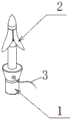
一种瓣膜环缩装置,包括锚定件、收紧线,所述锚定件包括锚定针、张紧片;所述锚定针包括穿刺头、连接杆、底座,所述穿刺头用于刺入心室内壁;所述连接杆具有限位凹槽,所述张紧片套插于连接杆外部并卡接于限位凹槽中;所述底座中部设有收紧线孔,供收紧线穿过;所述底座的底部设有与输送装置的推送杆可拆卸连接的连接孔。A valve annulus retraction device includes an anchor and a tightening wire, the anchor includes an anchor needle and a tension sheet; the anchor needle includes a puncture head, a connecting rod, and a base, and the puncture head is used for penetrate into the inner wall of the ventricle; the connecting rod has a limiting groove, the tensioning sheet sleeve is inserted outside the connecting rod and clamped in the limiting groove; the middle of the base is provided with a tightening wire hole for tightening The wire passes through; the bottom of the base is provided with a connection hole which is detachably connected with the push rod of the conveying device.
进一步的,所述张紧片包括管状结构和叶片结构,所述张紧片的管状结构与连接杆的限位凹槽贴合,以防止张紧片沿着限位凹槽轴向滑动;所述叶片结构包括至少2个向外弯曲的叶片。Further, the tensioning sheet includes a tubular structure and a blade structure, and the tubular structure of the tensioning sheet fits with the limiting groove of the connecting rod, so as to prevent the tensioning sheet from sliding axially along the limiting groove; The blade structure includes at least 2 outwardly curved blades.
进一步的,所述张紧片一侧具有裂口,用于使张紧片套插于连接杆外部。Further, one side of the tension piece is provided with a slit, which is used for inserting the tension piece sleeve outside the connecting rod.
进一步的,所述叶片呈喇叭口状,所述呈喇叭状的叶片夹角范围为30°~90°。Further, the blades are in the shape of a bell mouth, and the included angle of the blades in the trumpet shape ranges from 30° to 90°.
进一步的,所述锚定件还包括限位插销,所述锚定针的连接杆以及张紧片的管状结构上均设有与限位插销相适配的安装孔,以使限位插销插入张紧片及锚定针的安装孔中。Further, the anchoring piece also includes a limit pin, and the connecting rod of the anchor pin and the tubular structure of the tensioning piece are provided with mounting holes adapted to the limit pin, so that the limit pin can be inserted. in the mounting holes of the tensioning piece and the anchoring needle.
进一步的,所述环缩装置还包括收紧旋钮,所述收紧旋钮与锚定针底座插接,所述收紧线与收紧旋钮的转轴连接,以使收紧线随着收紧旋钮在锚定针底座的转动而收紧。Further, the ring shrinking device further includes a tightening knob, the tightening knob is inserted into the anchoring needle base, and the tightening wire is connected with the rotating shaft of the tightening knob, so that the tightening wire follows the tightening knob. Tighten while the anchor pin base is turned.
进一步的,所述收紧旋钮侧面设有与输送装置的推送杆套接的插槽,以使收紧旋钮随着推送杆的转动而转动。Further, the side of the tightening knob is provided with a slot that is sleeved with the push rod of the conveying device, so that the tightening knob rotates with the rotation of the push rod.
进一步的,所述可拆卸连接方式包括螺纹连接、卡扣连接。Further, the detachable connection method includes screw connection and snap connection.
进一步的,所述锚定件外具有覆膜,以增加环缩装置内皮化的速度。Further, the anchoring member is provided with a coating to increase the speed of endothelialization of the ring-shrinking device.
进一步的,所述张紧片采用记忆金属制成;所述收紧线的材料包括与生物相容较高的高分子材料、金属材料,所述覆膜材料为高分子材料。Further, the tensioning sheet is made of memory metal; the material of the tightening wire includes a polymer material and a metal material with high biocompatibility, and the film coating material is a polymer material.
与现有技术相比,本发明的环缩术保留了二尖瓣的瓣叶与瓣下结构,最大程度的保留了左心室结构,减缓了心脏衰退;且提高了二尖瓣反流的治疗效果。Compared with the prior art, the annulus retraction of the present invention preserves the leaflet and subvalvular structure of the mitral valve, preserves the left ventricular structure to the greatest extent, slows down the heart recession, and improves the treatment of mitral valve regurgitation. Effect.
附图说明Description of drawings
图1为实施例一提供的锚定件的结构示意图;FIG. 1 is a schematic structural diagram of an anchor provided in
图2为实施例一提供的锚定件的结构及限位插销的示意图;FIG. 2 is a schematic diagram of the structure of the anchor and the limit plug provided in the first embodiment;
图3为实施例一提供的锚定针的剖面三维示意图;3 is a cross-sectional three-dimensional schematic diagram of the anchoring needle provided in
图4为实施例一提供的用张紧片的结构示意图;4 is a schematic structural diagram of a tensioner sheet provided by
图5为实施例一提供的锚定件的结构及收紧旋钮示意图;5 is a schematic diagram of the structure of the anchor and the tightening knob provided in the first embodiment;
图6为实施例一提供的锚定件装载状态下的结构示意图;6 is a schematic structural diagram of the anchor provided in
图7为实施例一提供的锚定件穿过心室内壁后初始状态的结构示意图;7 is a schematic structural diagram of the initial state of the anchoring member provided in
图8为实施例一提供的收紧旋钮内部结构示意图;8 is a schematic diagram of the internal structure of the tightening knob provided in
图9为实施例一提供的收紧线与转轴连接的示意图;9 is a schematic diagram of the connection between the tightening wire and the rotating shaft provided by
图10为实施例一提供的覆膜、锚定件、收紧线和收紧旋钮植入心室壁不同位置后的示意图;10 is a schematic diagram of the membrane, anchor, tightening wire and tightening knob provided in Example 1 after being implanted in different positions of the ventricular wall;
图11为实施例一提供的拉紧收紧线后心室壁的示意图;11 is a schematic diagram of the ventricular wall after tightening the tightening wire provided in
图12为实施例二提供的锚定针为回转结构的装载状态下的示意图;FIG. 12 is a schematic diagram of the anchor needle provided in the second embodiment in a loaded state with a rotating structure;
图13为实施例二提供的锚定针为回转结构的初始状态下的示意图;13 is a schematic diagram of the initial state of the anchoring needle provided in the second embodiment in a rotating structure;
图14为实施例三提供的锚定件为螺旋结构的结构示意图;14 is a schematic structural diagram in which the anchor provided by the third embodiment is a helical structure;
其中:100.锚定件;1.锚定针;11.穿刺头;12.连接杆;121.限位凹槽;122.第一安装孔13.底座;131.第一收紧线孔;132.第一连接孔;2.张紧片;21.管状结构;211.第二安装孔;22.叶片;23.裂口;3.收紧线;4.收紧旋钮;41.插槽;42.棘轮;43.转轴;44.止回棘爪;5.限位插销;6.覆膜;7.输送装置;8.心室内壁;91a.第一头端;91b.第二头端;92.拉环;93a.第一钩状结构;93b.第二钩状结构;101.针尖结构;102.螺旋结构;103.第二收紧线孔;104.第二连接孔。1. Anchoring needle; 11. Piercing head; 12. Connecting rod; 121. Limiting groove; 122.
具体实施方式Detailed ways
以下通过特定的具体实例说明本发明的实施方式,本领域技术人员可由本说明书所揭露的内容轻易地了解本发明的其他优点与功效。本发明还可以通过另外不同的具体实施方式加以实施或应用,本说明书中的各项细节也可以基于不同观点与应用,在没有背离本发明的精神下进行各种修饰或改变。需说明的是,在不冲突的情况下,以下实施例及实施例中的特征可以相互组合。The embodiments of the present invention are described below through specific specific examples, and those skilled in the art can easily understand other advantages and effects of the present invention from the contents disclosed in this specification. The present invention can also be implemented or applied through other different specific embodiments, and various details in this specification can also be modified or changed based on different viewpoints and applications without departing from the spirit of the present invention. It should be noted that the following embodiments and features in the embodiments may be combined with each other under the condition of no conflict.
本发明的目的是针对现有技术的缺陷,提供一种瓣膜环缩装置。The purpose of the present invention is to provide a valve annulus retraction device in view of the defects of the prior art.
实施例一:Example 1:
如图1-11所示,本实施例提供一种瓣膜环缩装置,包括锚定件100、收紧线3、收紧旋钮4,锚定件包括锚定针1、张紧片2、限位插销5;锚定针1包括穿刺头11、连接杆12、底座13,其中,穿刺头11类似于一个锥形的尖端,用于刺入心室内壁8;连接杆12靠近穿刺头11的位置具有限位凹槽121,张紧片2套插于连接杆12外部并卡接于限位凹槽121中;底座13中部设有第一收紧线孔131,供收紧线3穿过;底座的底部设有与输送装置7的推送杆可拆卸连接的第一连接孔132,其中,可拆卸连接方式包括螺纹连接、卡扣连接。As shown in FIGS. 1-11 , this embodiment provides a valve annulus retraction device, which includes an anchoring
张紧片2由圆管制作而成,外层表面为抛光表面;将圆管的空腔分为封闭端面和开口端面,且空腔的横截面尺寸自封闭端面向开口端面依次递增,其中,封闭端面为张紧片2的管状结构21、开口端面为张紧片2的叶片结构。管状结构21的内径受外力形变,且与管状结构21的内壁与限位凹槽121完全贴合,便于套插在锚定针1中的同时以防止张紧片2沿着限位凹槽121轴向滑动,叶片结构的被切割形成开口,并被分出至少2个叶片22,优选3个,其中叶片22向外弯曲,向外弯曲的叶片22经过热定型呈喇叭口状,热定型后呈喇叭口状的叶片的夹角范围为30°~90°。故在原始状态下,锚定件呈伞状或盘状。张紧片2的一侧被切割形成裂口23,便于径向收缩,使张紧片2套插于连接杆12外部。The
锚定针1连接杆12的限位凹槽121上设有与限位插销5相适配的第一安装孔122,张紧片2的管状结构21上设有与限位插销4相适配的第二安装孔211,其中第一安装孔122与第二安装孔211的位置相对应,以使限位插销5插入张紧片的第二安装孔211及锚定针的第一安装孔122中,以限制张紧片2轴向转动。需要说明的是,限制张紧片2轴向转动也可用其他方式限位,如细线缝合、激光焊接等,可根据实际情况选择。The limiting
在本实施例中,张紧片2用记忆金属制成,优选记忆合金,其中记忆合金优选镍钛合金,镍钛合金是能将自身的塑性变形在某一特定温度下自动恢复为原始形状的特种合金。记忆合金具有复原性,在原始状态下的锚定件呈伞状或盘状,以保证其能固定在瓣环壁上。In this embodiment, the
将张紧片2采用记忆合金制成后,能够在第一环境下压缩至一收拢状态,并能够在第二环境下恢复至原始状态。例如在输送过程中被输送装置7约束成收缩状态,使其不会占用太多径向空间,当完成铆入后,形状记忆金属恢复为伞状或盘状,从而达到锚固效果。如图6为张紧片2收缩的状态,图7是张紧片2舒展后的状态。锚定件与输送装置的推送杆可拆卸连接,锚定件完成植入后推送杆可手动与之脱离,进而进行下一步操作。After the
在本实施例中,锚定件在装配完成后,锚定针1的穿刺头11底部直径略大于张紧片2管状结构21顶部的直径,以便于植入人体组织。In this embodiment, after the anchoring piece is assembled, the bottom diameter of the
收紧线3为与生物相容较高的高分子材料或者较为柔软的金属材料。优选使用独特的纳米复丝,复合喷丝技术制备的医用缝合线用途十分的广泛,首先应用最广泛的为生物医用功能材料,由于复合喷丝技术的瓣膜缝合线具有良好的结构相容性和生物相容性,所以在生物膜、医药支架、缓释药物等方面得到了广泛的应用,可以保证强度的同时,可以更好的内皮化。其次由复合喷丝技术的瓣膜缝合线具有大的比表面积,因此是一种理想的内皮化材料。除此之外由于由复合喷丝技术的瓣膜缝合线比普通的缝合线具有更强的物理性能,因此会在制备心脏瓣膜的过程中有着重要的应用。缝合线复合喷丝法制备的缝合线还被应用于传感器、电子材料、新型特殊纤维等、服装等。使用复合喷丝的方法将聚合物纺织到线上,使线的表面上形成一层致密的纳米纤维膜,这种表面带有纳米纤维膜的线可以被运用到多种场合,最常见的就是运用到医疗上。The
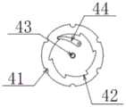
收紧旋钮4为圆柱体,外侧设有插槽41,用于套接输送装置的推送杆,以使收紧旋钮4随着推送杆的转动而转动。收紧旋钮4内部采用内呲合棘轮机构,包括棘轮42、转轴43和止回棘爪44,转动收紧旋钮4时止回棘爪44在棘轮42的齿背上滑动;若逆向转动旋钮,止回棘爪44便插入棘轮42的齿槽中,阻止棘轮42发生逆方向转动,因此收紧旋钮只能单方向旋转。需要说明的是,棘轮机构与现有技术中的原理类似,在此不多做赘述。The tightening
在本实施例中,如图9所示,收紧旋钮4与锚定针底座13插接,收紧线3与收紧旋钮4的转轴43连接,如将收紧线3缠绕于转轴43上,以使收紧线3随着收紧旋钮4在锚定针底座13的转动而收紧,且由于收紧旋钮4只能单方向旋转,因此解决了收紧线3回弹的问题。In this embodiment, as shown in FIG. 9 , the tightening
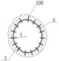
锚定件外具有覆膜6,以增加环缩装置内皮化的速度。覆膜6的材料选用PET或PTFE,制备工艺优选复合喷丝技术。传统的普通覆膜需要8-16月,甚至更长的时间才能完成的内皮化过程,本实施例中的覆膜2-3个月就可以内皮化完成,这得益于复合喷丝技术。There is a
将上述环缩装置应用于治疗二尖瓣反流的手术是的使用方法为:The method of applying the above-mentioned ring retraction device to the operation for treating mitral valve regurgitation is as follows:
将输送装置的导引鞘管经心尖/动脉进入到达瓣环,并通过导引鞘管的内腔送入导管,并调整导管的位置,使其与瓣环贴合,通过导管将锚定件外的覆膜输送至指定位置;在体外先将收紧线的一端穿过锚定针底座的收紧线孔并打结,将输送装置的推送杆与底座的底部连接,并将第一个锚定件输送至目标位置,并使得锚定件的穿刺头刺入心室内壁,将锚定件的穿刺头、连接杆、张紧片均刺入心室内壁中然后将输送装置撤回;再将第二、第三、….第N个锚定件以相同的方式刺入心室内壁(锚定件的数量根据实际情况来确定);此时多个锚定件串联在收紧线中,然后输送装置的推送杆套接与收紧旋钮的外侧,且将收紧线缠绕于收紧旋钮的转轴上,将收紧旋钮输送至最后一个刺入心室内壁的锚定件的底座处,将收紧旋钮插接于锚定件的底座,通过外力旋转推送杆,以使收紧旋钮随着推送杆的转动而转动,且使收紧线随着收紧旋钮在锚定针底座的转动而收紧,当将二尖瓣瓣环周长缩短之后即可将收紧线打结并切断,完成手术,撤回输送装置,如图10所示。瓣环处只留下多个锚定件、收紧旋钮、锚定件外的覆膜以及将多个锚定件串联在一起的收紧线,如图8所示。The introducer sheath of the delivery device is inserted through the apex/arterial to the valve annulus, and the catheter is sent through the lumen of the introducer sheath, and the position of the catheter is adjusted so that it fits with the valve annulus, and the anchor is passed through the catheter. The outer film is delivered to the designated position; outside the body, one end of the tightening thread is passed through the tightening thread hole of the anchoring needle base and knotted, and the push rod of the delivery device is connected to the bottom of the base, and the first The anchor is delivered to the target position, and the puncture head of the anchor is pierced into the ventricular inner wall, the puncture head, the connecting rod and the tension piece of the anchor are all pierced into the ventricular inner wall, and then the delivery device is withdrawn; The second, third, .... Nth anchors penetrate the ventricle wall in the same way (the number of anchors is determined according to the actual situation); at this time, multiple anchors are connected in series in the tightening line, and then delivered The push rod of the device is sleeved with the outside of the tightening knob, and the tightening wire is wound on the rotating shaft of the tightening knob, and the tightening knob is transported to the base of the last anchor that penetrates the inner wall of the ventricle, and the tightening The knob is inserted into the base of the anchor, and the push rod is rotated by external force, so that the tightening knob rotates with the rotation of the push rod, and the tightening line is tightened with the rotation of the tightening knob at the anchor needle base , when the mitral valve annulus circumference is shortened, the tightening line can be knotted and cut off, the operation is completed, and the delivery device is withdrawn, as shown in Figure 10. Only multiple anchors, tightening knobs, membranes outside the anchors, and tightening wires connecting the multiple anchors in series are left at the valve annulus, as shown in Figure 8 .
本实施例的环缩术保留了二尖瓣的瓣叶与瓣下结构,最大程度的保留了左心室结构,减缓了心脏衰退;且提高了二尖瓣反流的治疗效果。The annulus retraction of this embodiment preserves the leaflets and subvalvular structures of the mitral valve, preserves the left ventricular structure to the greatest extent, slows down cardiac recession, and improves the treatment effect of mitral regurgitation.
实施例二
本实施例提供的一种瓣膜环缩装置与实施例一的不同之处在于:The difference between the valve annulus device provided in this embodiment and
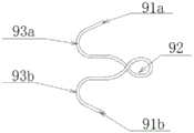
本实施例的锚定针采用回转结构,如图12-13所示,材质为记忆合金。锚定针在输送过程中装载于输送管内,头端的两个分支第一头端91a和第二头端91b被输送管约束至轴向方向,当到达预定位置后推动推送杆,锚定针头端分支91a和91b即刺入目标位置,锚定针中间部位回转形成拉环92,可供收紧线3穿过多个锚定件进项收紧。当完成铆入后,头端分支第一头端91a和第二头端91b恢复至初始状态下的钩状结构:第一钩状结构93a和第二钩状结构93b,如图13所示。此时由于扩展形状具有明显大于收缩形状的横截面,同时锚定针是刚性的,可将锚定针固定在人体组织内部。The anchoring needle in this embodiment adopts a rotary structure, as shown in Figures 12-13, and is made of memory alloy. The anchoring needle is loaded into the delivery tube during the delivery process, and the two branches of the head end, the first
本实施例的锚定针采用回转结构,可以确保锚定针稳定的保持扩展形状不发生任何变形,可牢牢的将锚定针固定在组织内部,进而避免现有技术的柔性锚定针无法稳定保持扩展形状而发生形变,易被拉脱的问题。The anchoring needle in this embodiment adopts a rotating structure, which can ensure that the anchoring needle can stably maintain the expanded shape without any deformation, and can firmly fix the anchoring needle inside the tissue, thereby avoiding the inability of the flexible anchoring needle in the prior art. Stable to maintain the expanded shape, deformation occurs, and it is easy to be pulled off.
实施例三
本实施例提供的一种瓣膜环缩装置与实施例一的不同之处在于:The difference between the valve annulus device provided in this embodiment and
本实施例锚定件采用螺旋结构,如图14所示,头端为针尖结构101,植入部分为螺旋结构102,连接部设有第二收紧线孔103,用于收紧线3通过,使所有锚定装置一一串联,连接部底端设有第二连接孔104,可与输送装置的推送杆之间可拆卸连接,连接方式包括螺纹连接,槽插连接,卡扣连接等。当到达预定位置后旋转推送杆,锚定装置即可螺旋植入人体组织内,逆向转动又可实现远距离脱离的操作。所述锚定装置植入人体组织后能够实现更大的锚定力,具有不易脱落、对人体损伤更小的有点。The anchor in this embodiment adopts a helical structure. As shown in FIG. 14 , the head end is a
本实施例的锚定装置采用螺旋结构,该螺旋结构的尖端刺入组织内部后,可大大增加锚定装置与心室内壁的接触面积,从而牢牢固定在组织内部,避免现有技术的柔性锚定针无法稳定保持扩展形状而发生形变,易被拉脱的问题。The anchoring device in this embodiment adopts a helical structure. After the tip of the helical structure penetrates the inside of the tissue, the contact area between the anchoring device and the inner wall of the ventricle can be greatly increased, so as to be firmly fixed inside the tissue, avoiding the flexible anchoring of the prior art. The fixed needle cannot stably maintain the expanded shape and is deformed and easily pulled off.
本文中所描述的具体实施例仅仅是对本发明精神作举例说明。本发明所属技术领域的技术人员可以对所描述的具体实施例做各种各样的修改或补充或采用类似的方式替代,但并不会偏离本发明的精神或者超越所附权利要求书所定义的范围。The specific embodiments described herein are merely illustrative of the spirit of the invention. Those skilled in the art to which the present invention pertains can make various modifications or additions to the described specific embodiments or substitute in similar manners, but will not deviate from the spirit of the present invention or go beyond the definitions of the appended claims range.
Claims (10)
Priority Applications (1)
| Application Number | Priority Date | Filing Date | Title |
|---|---|---|---|
| CN202010254342.1ACN111467082A (en) | 2020-04-02 | 2020-04-02 | Valve ring contracts device |
Applications Claiming Priority (1)
| Application Number | Priority Date | Filing Date | Title |
|---|---|---|---|
| CN202010254342.1ACN111467082A (en) | 2020-04-02 | 2020-04-02 | Valve ring contracts device |
Publications (1)
| Publication Number | Publication Date |
|---|---|
| CN111467082Atrue CN111467082A (en) | 2020-07-31 |
Family
ID=71750400
Family Applications (1)
| Application Number | Title | Priority Date | Filing Date |
|---|---|---|---|
| CN202010254342.1APendingCN111467082A (en) | 2020-04-02 | 2020-04-02 | Valve ring contracts device |
Country Status (1)
| Country | Link |
|---|---|
| CN (1) | CN111467082A (en) |
Cited By (5)
| Publication number | Priority date | Publication date | Assignee | Title |
|---|---|---|---|---|
| CN112294494A (en)* | 2020-08-18 | 2021-02-02 | 上海竑宇医疗科技有限公司 | Ring retractor and mounting method thereof |
| CN113180889A (en)* | 2021-03-26 | 2021-07-30 | 启晨(上海)医疗器械有限公司 | Mitral valve replacement device and use method thereof |
| CN115024862A (en)* | 2021-09-03 | 2022-09-09 | 杭州德晋医疗科技有限公司 | Implants, transcatheter ring retraction systems and their applications with reduced risk of shedding |
| CN115486974A (en)* | 2022-11-18 | 2022-12-20 | 上海御瓣医疗科技有限公司 | Detachable sharp end for assisting valve implantation |
| CN116269941A (en)* | 2023-05-11 | 2023-06-23 | 科瑞迈吉(北京)医疗科技有限公司 | Valve annulus contraction operation system with adjustable annulus contraction force single point |
Citations (9)
| Publication number | Priority date | Publication date | Assignee | Title |
|---|---|---|---|---|
| US20070051377A1 (en)* | 2003-11-12 | 2007-03-08 | Medtronic Vascular, Inc. | Cardiac valve annulus reduction system |
| CN104523353A (en)* | 2014-12-24 | 2015-04-22 | 金仕生物科技(常熟)有限公司 | Valvula-holding machine for artificial valvula bicuspidalis |
| CN106821548A (en)* | 2017-04-01 | 2017-06-13 | 上海纽脉医疗科技有限公司 | Through conduit artificial mitral valve forming ring apparatus and system |
| CN107252327A (en)* | 2016-10-21 | 2017-10-17 | 塞佩赫·法里亚比 | Tissue-attaching device for percutaneous treatment of mitral regurgitation |
| US20180289474A1 (en)* | 2017-04-05 | 2018-10-11 | Opus Medical Therapies, LLC | Transcatheter atrial sealing skirt, anchor, and tether and methods of implantation |
| CN109498216A (en)* | 2018-12-25 | 2019-03-22 | 乐普(北京)医疗器械股份有限公司 | A puller wire locking catheter for valve repair |
| CN109602464A (en)* | 2019-01-31 | 2019-04-12 | 上海诺强医疗科技有限公司 | Annulus constrictor |
| CN110742662A (en)* | 2019-11-22 | 2020-02-04 | 茵络(无锡)医疗器械有限公司 | Anchor structures for implanted tissue |
| CN212234800U (en)* | 2020-04-02 | 2020-12-29 | 科凯(南通)生命科学有限公司 | Valve ring contracts device |
- 2020
- 2020-04-02CNCN202010254342.1Apatent/CN111467082A/enactivePending
Patent Citations (9)
| Publication number | Priority date | Publication date | Assignee | Title |
|---|---|---|---|---|
| US20070051377A1 (en)* | 2003-11-12 | 2007-03-08 | Medtronic Vascular, Inc. | Cardiac valve annulus reduction system |
| CN104523353A (en)* | 2014-12-24 | 2015-04-22 | 金仕生物科技(常熟)有限公司 | Valvula-holding machine for artificial valvula bicuspidalis |
| CN107252327A (en)* | 2016-10-21 | 2017-10-17 | 塞佩赫·法里亚比 | Tissue-attaching device for percutaneous treatment of mitral regurgitation |
| CN106821548A (en)* | 2017-04-01 | 2017-06-13 | 上海纽脉医疗科技有限公司 | Through conduit artificial mitral valve forming ring apparatus and system |
| US20180289474A1 (en)* | 2017-04-05 | 2018-10-11 | Opus Medical Therapies, LLC | Transcatheter atrial sealing skirt, anchor, and tether and methods of implantation |
| CN109498216A (en)* | 2018-12-25 | 2019-03-22 | 乐普(北京)医疗器械股份有限公司 | A puller wire locking catheter for valve repair |
| CN109602464A (en)* | 2019-01-31 | 2019-04-12 | 上海诺强医疗科技有限公司 | Annulus constrictor |
| CN110742662A (en)* | 2019-11-22 | 2020-02-04 | 茵络(无锡)医疗器械有限公司 | Anchor structures for implanted tissue |
| CN212234800U (en)* | 2020-04-02 | 2020-12-29 | 科凯(南通)生命科学有限公司 | Valve ring contracts device |
Cited By (8)
| Publication number | Priority date | Publication date | Assignee | Title |
|---|---|---|---|---|
| CN112294494A (en)* | 2020-08-18 | 2021-02-02 | 上海竑宇医疗科技有限公司 | Ring retractor and mounting method thereof |
| CN113180889A (en)* | 2021-03-26 | 2021-07-30 | 启晨(上海)医疗器械有限公司 | Mitral valve replacement device and use method thereof |
| CN115024862A (en)* | 2021-09-03 | 2022-09-09 | 杭州德晋医疗科技有限公司 | Implants, transcatheter ring retraction systems and their applications with reduced risk of shedding |
| CN115486974A (en)* | 2022-11-18 | 2022-12-20 | 上海御瓣医疗科技有限公司 | Detachable sharp end for assisting valve implantation |
| CN115486974B (en)* | 2022-11-18 | 2023-03-14 | 上海御瓣医疗科技有限公司 | Detachable tip for assisting valve implantation |
| CN116269941A (en)* | 2023-05-11 | 2023-06-23 | 科瑞迈吉(北京)医疗科技有限公司 | Valve annulus contraction operation system with adjustable annulus contraction force single point |
| CN116269941B (en)* | 2023-05-11 | 2023-08-08 | 科瑞迈吉(北京)医疗科技有限公司 | Valve annulus contraction operation system with adjustable annulus contraction force single point |
| US11980546B1 (en) | 2023-05-11 | 2024-05-14 | Creative Medtech (Beijing) Co., Ltd | Valve annulus contraction surgical system with adjustable annulus contracting force at single point |
Similar Documents
| Publication | Publication Date | Title |
|---|---|---|
| CN111467082A (en) | Valve ring contracts device | |
| US11554016B2 (en) | Artificial chordae tendineae implantation system | |
| CN102348419B (en) | artificial tendon | |
| CN103491901B (en) | Device and method for heart valve repair | |
| JP6526000B2 (en) | Sealing devices, related delivery devices and their use | |
| CN102548488B (en) | Surgical puncture cinch and closure system | |
| US11648108B2 (en) | Heart valve prosthesis | |
| US8579967B2 (en) | Valve aptation assist device | |
| WO2019184649A1 (en) | Heart valve repair system and suture locking device thereof | |
| US20110190811A1 (en) | System and method for providing access and closure to tissue | |
| US20150250590A1 (en) | Transapical mitral chordae replacement | |
| JP2009538638A (en) | Annuloplasty device with helical anchor and method of use | |
| CN111616837B (en) | A mitral valve annulus contraction device | |
| JP2011507653A (en) | Automatic assist device for inserting and securing annulus or prosthesis using clips | |
| WO2014143161A1 (en) | Securing bidirectional suture loops using coaxial mechanical fasteners | |
| CN112451174A (en) | Interventional transapical artificial heart valve conveying system | |
| CN209404889U (en) | A new atrial septostomy device assembly | |
| CN212234800U (en) | Valve ring contracts device | |
| CN212281775U (en) | Mitral valve annular device that contracts | |
| CN114681132A (en) | Heart valve repair device | |
| WO2022262117A1 (en) | Anchoring device for heart valve | |
| WO2022027941A1 (en) | Implant and assembly used in forming same | |
| US20230414825A1 (en) | Suture encapsulation processes and systems | |
| CN113274167A (en) | Edge-to-edge repair device and edge-to-edge repair system | |
| HK1175677B (en) | System for providing access and closure to tissue |
Legal Events
| Date | Code | Title | Description |
|---|---|---|---|
| PB01 | Publication | ||
| PB01 | Publication | ||
| SE01 | Entry into force of request for substantive examination | ||
| SE01 | Entry into force of request for substantive examination | ||
| CB02 | Change of applicant information | ||
| CB02 | Change of applicant information | Address after:No.10 Yongfu Road, shibeikeji City, Gangzha District, Nantong City, Jiangsu Province, 226000 Applicant after:KEKAI (NANTONG) LIFE SCIENCE Co.,Ltd. Address before:2269, Liugang Road, Nantong City, Jiangsu Province Applicant before:KEKAI (NANTONG) LIFE SCIENCE Co.,Ltd. |