CN111466820B - Handheld Surface Cleaning Devices - Google Patents
Handheld Surface Cleaning DevicesDownload PDFInfo
- Publication number
- CN111466820B CN111466820BCN202010302794.2ACN202010302794ACN111466820BCN 111466820 BCN111466820 BCN 111466820BCN 202010302794 ACN202010302794 ACN 202010302794ACN 111466820 BCN111466820 BCN 111466820B
- Authority
- CN
- China
- Prior art keywords
- cleaning device
- surface cleaning
- dust cup
- handheld surface
- handheld
- Prior art date
- Legal status (The legal status is an assumption and is not a legal conclusion. Google has not performed a legal analysis and makes no representation as to the accuracy of the status listed.)
- Active
Links
Images


Classifications
- A—HUMAN NECESSITIES
- A47—FURNITURE; DOMESTIC ARTICLES OR APPLIANCES; COFFEE MILLS; SPICE MILLS; SUCTION CLEANERS IN GENERAL
- A47L—DOMESTIC WASHING OR CLEANING; SUCTION CLEANERS IN GENERAL
- A47L5/00—Structural features of suction cleaners
- A47L5/12—Structural features of suction cleaners with power-driven air-pumps or air-compressors, e.g. driven by motor vehicle engine vacuum
- A47L5/22—Structural features of suction cleaners with power-driven air-pumps or air-compressors, e.g. driven by motor vehicle engine vacuum with rotary fans
- A47L5/24—Hand-supported suction cleaners
- A—HUMAN NECESSITIES
- A47—FURNITURE; DOMESTIC ARTICLES OR APPLIANCES; COFFEE MILLS; SPICE MILLS; SUCTION CLEANERS IN GENERAL
- A47L—DOMESTIC WASHING OR CLEANING; SUCTION CLEANERS IN GENERAL
- A47L11/00—Machines for cleaning floors, carpets, furniture, walls, or wall coverings
- A47L11/24—Floor-sweeping machines, motor-driven
- A—HUMAN NECESSITIES
- A47—FURNITURE; DOMESTIC ARTICLES OR APPLIANCES; COFFEE MILLS; SPICE MILLS; SUCTION CLEANERS IN GENERAL
- A47L—DOMESTIC WASHING OR CLEANING; SUCTION CLEANERS IN GENERAL
- A47L5/00—Structural features of suction cleaners
- A47L5/12—Structural features of suction cleaners with power-driven air-pumps or air-compressors, e.g. driven by motor vehicle engine vacuum
- A47L5/22—Structural features of suction cleaners with power-driven air-pumps or air-compressors, e.g. driven by motor vehicle engine vacuum with rotary fans
- A47L5/225—Convertible suction cleaners, i.e. convertible between different types thereof, e.g. from upright suction cleaners to sledge-type suction cleaners
- A—HUMAN NECESSITIES
- A47—FURNITURE; DOMESTIC ARTICLES OR APPLIANCES; COFFEE MILLS; SPICE MILLS; SUCTION CLEANERS IN GENERAL
- A47L—DOMESTIC WASHING OR CLEANING; SUCTION CLEANERS IN GENERAL
- A47L5/00—Structural features of suction cleaners
- A47L5/12—Structural features of suction cleaners with power-driven air-pumps or air-compressors, e.g. driven by motor vehicle engine vacuum
- A47L5/22—Structural features of suction cleaners with power-driven air-pumps or air-compressors, e.g. driven by motor vehicle engine vacuum with rotary fans
- A47L5/24—Hand-supported suction cleaners
- A47L5/26—Hand-supported suction cleaners with driven dust-loosening tools
- A—HUMAN NECESSITIES
- A47—FURNITURE; DOMESTIC ARTICLES OR APPLIANCES; COFFEE MILLS; SPICE MILLS; SUCTION CLEANERS IN GENERAL
- A47L—DOMESTIC WASHING OR CLEANING; SUCTION CLEANERS IN GENERAL
- A47L9/00—Details or accessories of suction cleaners, e.g. mechanical means for controlling the suction or for effecting pulsating action; Storing devices specially adapted to suction cleaners or parts thereof; Carrying-vehicles specially adapted for suction cleaners
- A47L9/0009—Storing devices ; Supports, stands or holders
- A47L9/0018—Storing devices ; Supports, stands or holders integrated in or removably mounted upon the suction cleaner for storing parts of said suction cleaner
- A—HUMAN NECESSITIES
- A47—FURNITURE; DOMESTIC ARTICLES OR APPLIANCES; COFFEE MILLS; SPICE MILLS; SUCTION CLEANERS IN GENERAL
- A47L—DOMESTIC WASHING OR CLEANING; SUCTION CLEANERS IN GENERAL
- A47L9/00—Details or accessories of suction cleaners, e.g. mechanical means for controlling the suction or for effecting pulsating action; Storing devices specially adapted to suction cleaners or parts thereof; Carrying-vehicles specially adapted for suction cleaners
- A47L9/009—Carrying-vehicles; Arrangements of trollies or wheels; Means for avoiding mechanical obstacles
- A—HUMAN NECESSITIES
- A47—FURNITURE; DOMESTIC ARTICLES OR APPLIANCES; COFFEE MILLS; SPICE MILLS; SUCTION CLEANERS IN GENERAL
- A47L—DOMESTIC WASHING OR CLEANING; SUCTION CLEANERS IN GENERAL
- A47L9/00—Details or accessories of suction cleaners, e.g. mechanical means for controlling the suction or for effecting pulsating action; Storing devices specially adapted to suction cleaners or parts thereof; Carrying-vehicles specially adapted for suction cleaners
- A47L9/02—Nozzles
- A47L9/04—Nozzles with driven brushes or agitators
- A47L9/0461—Dust-loosening tools, e.g. agitators, brushes
- A47L9/0466—Rotating tools
- A47L9/0477—Rolls
- A—HUMAN NECESSITIES
- A47—FURNITURE; DOMESTIC ARTICLES OR APPLIANCES; COFFEE MILLS; SPICE MILLS; SUCTION CLEANERS IN GENERAL
- A47L—DOMESTIC WASHING OR CLEANING; SUCTION CLEANERS IN GENERAL
- A47L9/00—Details or accessories of suction cleaners, e.g. mechanical means for controlling the suction or for effecting pulsating action; Storing devices specially adapted to suction cleaners or parts thereof; Carrying-vehicles specially adapted for suction cleaners
- A47L9/10—Filters; Dust separators; Dust removal; Automatic exchange of filters
- A47L9/106—Dust removal
- A—HUMAN NECESSITIES
- A47—FURNITURE; DOMESTIC ARTICLES OR APPLIANCES; COFFEE MILLS; SPICE MILLS; SUCTION CLEANERS IN GENERAL
- A47L—DOMESTIC WASHING OR CLEANING; SUCTION CLEANERS IN GENERAL
- A47L9/00—Details or accessories of suction cleaners, e.g. mechanical means for controlling the suction or for effecting pulsating action; Storing devices specially adapted to suction cleaners or parts thereof; Carrying-vehicles specially adapted for suction cleaners
- A47L9/10—Filters; Dust separators; Dust removal; Automatic exchange of filters
- A47L9/12—Dry filters
- A—HUMAN NECESSITIES
- A47—FURNITURE; DOMESTIC ARTICLES OR APPLIANCES; COFFEE MILLS; SPICE MILLS; SUCTION CLEANERS IN GENERAL
- A47L—DOMESTIC WASHING OR CLEANING; SUCTION CLEANERS IN GENERAL
- A47L9/00—Details or accessories of suction cleaners, e.g. mechanical means for controlling the suction or for effecting pulsating action; Storing devices specially adapted to suction cleaners or parts thereof; Carrying-vehicles specially adapted for suction cleaners
- A47L9/10—Filters; Dust separators; Dust removal; Automatic exchange of filters
- A47L9/16—Arrangement or disposition of cyclones or other devices with centrifugal action
- A47L9/165—Construction of inlets
- A—HUMAN NECESSITIES
- A47—FURNITURE; DOMESTIC ARTICLES OR APPLIANCES; COFFEE MILLS; SPICE MILLS; SUCTION CLEANERS IN GENERAL
- A47L—DOMESTIC WASHING OR CLEANING; SUCTION CLEANERS IN GENERAL
- A47L9/00—Details or accessories of suction cleaners, e.g. mechanical means for controlling the suction or for effecting pulsating action; Storing devices specially adapted to suction cleaners or parts thereof; Carrying-vehicles specially adapted for suction cleaners
- A47L9/10—Filters; Dust separators; Dust removal; Automatic exchange of filters
- A47L9/16—Arrangement or disposition of cyclones or other devices with centrifugal action
- A47L9/1691—Mounting or coupling means for cyclonic chamber or dust receptacles
- A—HUMAN NECESSITIES
- A47—FURNITURE; DOMESTIC ARTICLES OR APPLIANCES; COFFEE MILLS; SPICE MILLS; SUCTION CLEANERS IN GENERAL
- A47L—DOMESTIC WASHING OR CLEANING; SUCTION CLEANERS IN GENERAL
- A47L9/00—Details or accessories of suction cleaners, e.g. mechanical means for controlling the suction or for effecting pulsating action; Storing devices specially adapted to suction cleaners or parts thereof; Carrying-vehicles specially adapted for suction cleaners
- A47L9/20—Means for cleaning filters
- A—HUMAN NECESSITIES
- A47—FURNITURE; DOMESTIC ARTICLES OR APPLIANCES; COFFEE MILLS; SPICE MILLS; SUCTION CLEANERS IN GENERAL
- A47L—DOMESTIC WASHING OR CLEANING; SUCTION CLEANERS IN GENERAL
- A47L9/00—Details or accessories of suction cleaners, e.g. mechanical means for controlling the suction or for effecting pulsating action; Storing devices specially adapted to suction cleaners or parts thereof; Carrying-vehicles specially adapted for suction cleaners
- A47L9/28—Installation of the electric equipment, e.g. adaptation or attachment to the suction cleaner; Controlling suction cleaners by electric means
- A47L9/2868—Arrangements for power supply of vacuum cleaners or the accessories thereof
- A47L9/2873—Docking units or charging stations
- A—HUMAN NECESSITIES
- A47—FURNITURE; DOMESTIC ARTICLES OR APPLIANCES; COFFEE MILLS; SPICE MILLS; SUCTION CLEANERS IN GENERAL
- A47L—DOMESTIC WASHING OR CLEANING; SUCTION CLEANERS IN GENERAL
- A47L9/00—Details or accessories of suction cleaners, e.g. mechanical means for controlling the suction or for effecting pulsating action; Storing devices specially adapted to suction cleaners or parts thereof; Carrying-vehicles specially adapted for suction cleaners
- A47L9/28—Installation of the electric equipment, e.g. adaptation or attachment to the suction cleaner; Controlling suction cleaners by electric means
- A47L9/2868—Arrangements for power supply of vacuum cleaners or the accessories thereof
- A47L9/2884—Details of arrangements of batteries or their installation
- A—HUMAN NECESSITIES
- A47—FURNITURE; DOMESTIC ARTICLES OR APPLIANCES; COFFEE MILLS; SPICE MILLS; SUCTION CLEANERS IN GENERAL
- A47L—DOMESTIC WASHING OR CLEANING; SUCTION CLEANERS IN GENERAL
- A47L9/00—Details or accessories of suction cleaners, e.g. mechanical means for controlling the suction or for effecting pulsating action; Storing devices specially adapted to suction cleaners or parts thereof; Carrying-vehicles specially adapted for suction cleaners
- A47L9/32—Handles
- A47L9/322—Handles for hand-supported suction cleaners
- A—HUMAN NECESSITIES
- A47—FURNITURE; DOMESTIC ARTICLES OR APPLIANCES; COFFEE MILLS; SPICE MILLS; SUCTION CLEANERS IN GENERAL
- A47L—DOMESTIC WASHING OR CLEANING; SUCTION CLEANERS IN GENERAL
- A47L9/00—Details or accessories of suction cleaners, e.g. mechanical means for controlling the suction or for effecting pulsating action; Storing devices specially adapted to suction cleaners or parts thereof; Carrying-vehicles specially adapted for suction cleaners
- A47L9/32—Handles
- A47L9/325—Handles for wheeled suction cleaners with steering handle
- A—HUMAN NECESSITIES
- A47—FURNITURE; DOMESTIC ARTICLES OR APPLIANCES; COFFEE MILLS; SPICE MILLS; SUCTION CLEANERS IN GENERAL
- A47L—DOMESTIC WASHING OR CLEANING; SUCTION CLEANERS IN GENERAL
- A47L2201/00—Robotic cleaning machines, i.e. with automatic control of the travelling movement or the cleaning operation
- A47L2201/02—Docking stations; Docking operations
- A47L2201/022—Recharging of batteries
- A—HUMAN NECESSITIES
- A47—FURNITURE; DOMESTIC ARTICLES OR APPLIANCES; COFFEE MILLS; SPICE MILLS; SUCTION CLEANERS IN GENERAL
- A47L—DOMESTIC WASHING OR CLEANING; SUCTION CLEANERS IN GENERAL
- A47L9/00—Details or accessories of suction cleaners, e.g. mechanical means for controlling the suction or for effecting pulsating action; Storing devices specially adapted to suction cleaners or parts thereof; Carrying-vehicles specially adapted for suction cleaners
- A47L9/10—Filters; Dust separators; Dust removal; Automatic exchange of filters
- A47L9/102—Dust separators
- A—HUMAN NECESSITIES
- A47—FURNITURE; DOMESTIC ARTICLES OR APPLIANCES; COFFEE MILLS; SPICE MILLS; SUCTION CLEANERS IN GENERAL
- A47L—DOMESTIC WASHING OR CLEANING; SUCTION CLEANERS IN GENERAL
- A47L9/00—Details or accessories of suction cleaners, e.g. mechanical means for controlling the suction or for effecting pulsating action; Storing devices specially adapted to suction cleaners or parts thereof; Carrying-vehicles specially adapted for suction cleaners
- A47L9/10—Filters; Dust separators; Dust removal; Automatic exchange of filters
- A47L9/16—Arrangement or disposition of cyclones or other devices with centrifugal action
- A47L9/1683—Dust collecting chambers; Dust collecting receptacles
Landscapes
- Engineering & Computer Science (AREA)
- Mechanical Engineering (AREA)
- Robotics (AREA)
- Nozzles For Electric Vacuum Cleaners (AREA)
- Electric Vacuum Cleaner (AREA)
- Cleaning In General (AREA)
- Filters For Electric Vacuum Cleaners (AREA)
- Electric Suction Cleaners (AREA)
- Drawers Of Furniture (AREA)
- Cleaning Implements For Floors, Carpets, Furniture, Walls, And The Like (AREA)
- Telephone Function (AREA)
- Brushes (AREA)
Abstract
Translated fromChinese
Description
Translated fromChinese本申请是申请日为2018年09月25日、申请号为CN 201811114067.2、名称为“手持式表面清洁装置”的发明专利申请的分案申请。This application is a divisional application of an invention patent application with an application date of September 25, 2018, an application number of CN 201811114067.2, and a title of "Handheld Surface Cleaning Device".
技术领域technical field
本发明一般涉及表面清洁装置,更具体地,涉及手持式表面清洁装置和实现该表面清洁装置的真空系统。The present invention relates generally to surface cleaning devices, and more particularly, to hand-held surface cleaning devices and vacuum systems for implementing such surface cleaning devices.
相关申请related application
本申请要求2017年9月22日提交的序列号为62/561,851的美国临时专利申请、2017年11月13日提交的序列号为62/585,320的美国临时专利申请、2018年1月12日提交的序列号为62/616,908的美国临时专利申请和2018年1月19日提交的序列号为62/619,309的美国临时专利申请的权益,这些美国临时专利申请中的每一个都通过引用被全部并入本文。This application claims U.S. Provisional Patent Application Serial No. 62/561,851 filed September 22, 2017, U.S. Provisional Patent Application Serial No. 62/585,320 filed November 13, 2017, filed January 12, 2018 U.S. Provisional Patent Application Serial No. 62/616,908 and U.S. Provisional Patent Application Serial No. 62/619,309 filed January 19, 2018, each of which is hereby incorporated by reference in its entirety into this article.
背景技术Background technique
真空吸尘器和其他表面装置可具有多个部件,每个部件从一个或多个电源(例如,一个或多个电池或电力干线)接收电力。例如,真空吸尘器可包括抽吸马达以在清洁头内产生真空。产生的真空从待清洁表面收集碎屑并将碎屑放置在碎屑收集器中。真空吸尘器还可包括马达,以使在清洁头内的刷辊旋转。刷辊的旋转对已粘附在待清洁表面上的碎屑进行搅拨,使得产生的真空能够将碎屑从该表面除去。除了用于清洁的电气部件之外,真空吸尘器还可包括一个或多个光源以照亮待清洁的区域。Vacuum cleaners and other surface appliances may have multiple components, each receiving power from one or more power sources (eg, one or more batteries or an electrical mains). For example, a vacuum cleaner may include a suction motor to create a vacuum within the cleaning head. The created vacuum collects debris from the surface to be cleaned and deposits the debris in the debris collector. The vacuum cleaner may also include a motor to rotate the brushroll within the cleaning head. The rotation of the brush roll agitates debris that has adhered to the surface to be cleaned so that the vacuum created can remove the debris from the surface. In addition to electrical components for cleaning, vacuum cleaners may also include one or more light sources to illuminate the area to be cleaned.
真空吸尘器通常在小房间或其他储存位置占据相对大量的空间。例如,直立的真空吸尘器在储存起来以备将来使用时,往往会保持在使用时的直立位置。为此,真空吸尘器的储存需要能够容纳该真空吸尘器的整体高度和宽度的空间。这通常会将真空吸尘器转移到看不见的地方(例如小房间、车库)或其他偏僻的地方的储存位置。这些位置可能与可能需要定期清洁的房间和其他位置相距一定距离,这可能因此导致较少地清洁那些位置,因为将真空吸尘器拖入和移出储存室可能是不能实行的或不方便的。Vacuum cleaners typically occupy a relatively large amount of space in a closet or other storage location. For example, upright vacuum cleaners tend to remain in the upright position they were in use when stored for future use. For this reason, storage of the vacuum cleaner requires a space capable of accommodating the overall height and width of the vacuum cleaner. This often moves the vacuum to an out-of-sight (e.g. cubby, garage) or other out-of-the-way storage location. These locations may be some distance away from rooms and other locations that may need to be cleaned regularly, which may therefore result in those locations being cleaned less often since it may not be practical or convenient to lug the vacuum cleaner into and out of the storage room.
附图说明Description of drawings
通过结合附图阅读以下详细描述,将更好地理解这些和其他特征的优点,在附图中:The advantages of these and other features will be better understood by reading the following detailed description in conjunction with the accompanying drawings, in which:
图1示出了根据本公开的实施例的手持式表面清洁装置的示例实施例。FIG. 1 illustrates an example embodiment of a handheld surface cleaning device according to embodiments of the present disclosure.
图2示出了根据本公开的实施例的图1的手持式表面清洁装置的俯视图。FIG. 2 illustrates a top view of the handheld surface cleaning device of FIG. 1 in accordance with an embodiment of the disclosure.
图3示出了根据本公开的实施例的图1的手持式表面清洁装置的侧视透视图。3 illustrates a side perspective view of the handheld surface cleaning device of FIG. 1 in accordance with an embodiment of the disclosure.
图4示出了根据本公开的实施例的沿着线4-4截取的图1的手持式表面清洁装置的横截面视图。4 illustrates a cross-sectional view of the handheld surface cleaning device of FIG. 1 taken along line 4 - 4 in accordance with an embodiment of the disclosure.
图5示出了适用于图1的手持式表面清洁装置的示例集尘杯。FIG. 5 illustrates an example dust cup suitable for use with the handheld surface cleaning device of FIG. 1 .
图6示出了根据本公开的实施例的图1的手持式表面清洁装置的另一横截面视图。6 illustrates another cross-sectional view of the handheld surface cleaning device of FIG. 1 in accordance with an embodiment of the disclosure.
图7示出了根据本公开的实施例的图1的手持式表面清洁装置的另一横截面视图。7 illustrates another cross-sectional view of the handheld surface cleaning device of FIG. 1 in accordance with an embodiment of the disclosure.
图8示出了具有用于接纳根据本公开的实施例的手持式表面清洁装置的容纳部的示例真空吸尘器框架。8 illustrates an example vacuum cleaner frame with a receptacle for receiving a handheld surface cleaning device according to an embodiment of the present disclosure.
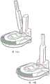
图9示出了由根据本公开的实施例的图8的示例真空吸尘器框架使用的示例集尘杯。FIG. 9 illustrates an example dust cup for use with the example vacuum cleaner frame of FIG. 8 according to an embodiment of the present disclosure.
图10示出了根据本公开的实施例的联接到插接部(dock)的手持式表面清洁装置的示例。10 illustrates an example of a handheld surface cleaning device coupled to a dock according to an embodiment of the disclosure.
图11示出了根据本公开的实施例的联接到插接部的手持式表面清洁装置的另一示例。11 illustrates another example of a handheld surface cleaning device coupled to a receptacle according to an embodiment of the disclosure.
图12示出了根据本公开的实施例的联接到插接部的手持式表面清洁装置的另一示例。12 illustrates another example of a handheld surface cleaning device coupled to a receptacle according to an embodiment of the disclosure.
图13A至图13D示出了根据本公开的实施例的联接到插接部的手持式表面清洁装置的另一示例。13A-13D illustrate another example of a handheld surface cleaning device coupled to a receptacle according to an embodiment of the disclosure.
图14A至图14C示出了根据本公开的实施例的联接到插接部的手持式表面清洁装置的另一示例。14A-14C illustrate another example of a handheld surface cleaning device coupled to a receptacle according to an embodiment of the disclosure.
图15A至图15C示出了根据本公开的实施例的联接到插接部的手持式表面清洁装置的另一示例。15A-15C illustrate another example of a handheld surface cleaning device coupled to a receptacle according to an embodiment of the disclosure.
图16A至图16C示出了根据本公开的实施例的联接到插接部的手持式表面清洁装置的另一示例。16A-16C illustrate another example of a handheld surface cleaning device coupled to a receptacle according to an embodiment of the disclosure.
图17A至图17C示出了根据本公开的实施例的联接到插接部的手持式表面清洁装置的另一示例。17A-17C illustrate another example of a handheld surface cleaning device coupled to a receptacle according to an embodiment of the disclosure.
图18A至图18C示出了根据本公开的实施例的联接到插接部的手持式表面清洁装置的另一示例。18A-18C illustrate another example of a handheld surface cleaning device coupled to a receptacle according to an embodiment of the disclosure.
图19A至图19B示出了根据本公开的实施例的联接到插接部的手持式表面清洁装置的另一示例。19A-19B illustrate another example of a handheld surface cleaning device coupled to a receptacle according to an embodiment of the disclosure.
图20A至图20B示出了根据本公开的实施例的联接到插接部的手持式表面清洁装置的另一示例。20A-20B illustrate another example of a handheld surface cleaning device coupled to a receptacle according to an embodiment of the disclosure.
图21示出了根据本公开的实施例的手持式表面清洁装置的透视图。21 shows a perspective view of a handheld surface cleaning device according to an embodiment of the disclosure.
图22A以分离的方式示出了根据本公开的实施例的图21的手持式表面清洁装置的本体部分的透视图。22A shows a perspective view of the body portion of the handheld surface cleaning device of FIG. 21 in isolation, according to an embodiment of the present disclosure.
图22B以分离的方式示出了根据本公开的实施例的图21的手持式表面清洁装置的本体部分的另一透视图。22B shows another perspective view of the body portion of the handheld surface cleaning device of FIG. 21 in isolation, according to an embodiment of the disclosure.
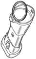
图23A示出了适用于根据本公开的实施例的图21的手持式表面清洁装置的示例电源。23A illustrates an example power supply suitable for use with the handheld surface cleaning device of FIG. 21 in accordance with an embodiment of the disclosure.
图23B示出了适用于根据本公开的实施例的图21的手持式表面清洁装置的另一示例电源。23B illustrates another example power supply suitable for use with the handheld surface cleaning device of FIG. 21 in accordance with an embodiment of the disclosure.
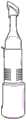
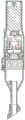
图23C示出了根据本公开的实施例的图21的手持式表面清洁装置的横截面视图。23C illustrates a cross-sectional view of the handheld surface cleaning device of FIG. 21 , according to an embodiment of the disclosure.
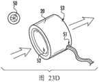
图23D示出了适用于根据本公开的实施例的图21的手持式表面清洁装置的示例马达。23D illustrates an example motor suitable for use with the handheld surface cleaning device of FIG. 21 in accordance with an embodiment of the disclosure.
图24A至图24C示出了根据本公开的另外的示例实施例。24A-24C illustrate additional example embodiments according to the present disclosure.
图25示出了根据本公开的示例手持式表面清洁装置。25 illustrates an example handheld surface cleaning device according to the present disclosure.
图26A示出了根据本公开的实施例的图25的手持式表面清洁装置的横截面视图。26A illustrates a cross-sectional view of the handheld surface cleaning device of FIG. 25, according to an embodiment of the disclosure.
图26B以分离的方式示出了根据本公开的实施例的图25的手持式表面清洁装置的示例清洁头。26B illustrates an example cleaning head of the handheld surface cleaning device of FIG. 25 in isolation, according to an embodiment of the disclosure.
图26C以分离的方式示出了根据本公开的实施例的图25的手持式表面清洁装置的示例手柄。26C illustrates an example handle of the handheld surface cleaning device of FIG. 25 in isolation, according to an embodiment of the disclosure.
图27示出了根据本公开的另一示例手持式表面清洁装置。27 illustrates another example handheld surface cleaning device according to the present disclosure.
图28A至图28C示出了根据本公开的实施例的表面清洁装置的另外的示例实施例。28A-28C illustrate additional example embodiments of surface cleaning devices according to embodiments of the present disclosure.
图29A至图29H示出了根据本公开的实施例的表面清洁装置的另外的示例实施例。29A-29H illustrate additional example embodiments of surface cleaning apparatus according to embodiments of the present disclosure.
图30A至图30C示出了根据本公开的实施例的表面清洁装置的另外的示例实施例。30A-30C illustrate additional example embodiments of surface cleaning apparatus according to embodiments of the present disclosure.
图31A示出了根据本公开的实施例的处于闭合位置/插接位置的表面清洁装置的另一示例。31A shows another example of a surface cleaning device in a closed/docked position according to an embodiment of the disclosure.
图31B示出了根据本公开的实施例的处于打开位置的表面清洁装置的另一示例。31B shows another example of a surface cleaning device in an open position, according to an embodiment of the disclosure.
图31C示出了图31A的沿着线C-C截取的表面清洁装置的横截面视图。31C shows a cross-sectional view of the surface cleaning device of FIG. 31A taken along line C-C.
图31D示出了图31B的沿着线D-D截取的表面清洁装置的横截面视图。Figure 3 ID shows a cross-sectional view of the surface cleaning device of Figure 3 IB taken along line D-D.
图32A至图32D示出了根据本公开的实施例的表面清洁装置的另外的示例实施例。32A-32D illustrate additional example embodiments of surface cleaning devices according to embodiments of the present disclosure.
图33示出了根据本公开的实施例的表面清洁装置的另一示例实施例。FIG. 33 illustrates another example embodiment of a surface cleaning device according to an embodiment of the present disclosure.
图34A至图34C示出了根据本公开的实施例的表面清洁装置的另外的示例实施例。34A-34C illustrate additional example embodiments of surface cleaning devices according to embodiments of the present disclosure.
图35A至图35B示出了根据本公开的实施例的表面清洁装置的另外的示例实施例。35A-35B illustrate additional example embodiments of surface cleaning devices according to embodiments of the present disclosure.
图36A至图36C示出了根据本公开的实施例的表面清洁装置的另外的示例实施例。36A-36C illustrate additional example embodiments of surface cleaning devices according to embodiments of the present disclosure.
图37示出了根据本公开的实施例的表面清洁装置的另一示例实施例。FIG. 37 illustrates another example embodiment of a surface cleaning device according to an embodiment of the present disclosure.
图38示出了根据本公开的实施例的图37的示例实施例的透视图。FIG. 38 shows a perspective view of the example embodiment of FIG. 37 according to an embodiment of the disclosure.
图39示出了根据本公开的实施例的图37的示例实施例的横截面视图。FIG. 39 illustrates a cross-sectional view of the example embodiment of FIG. 37 in accordance with an embodiment of the present disclosure.
图40示出了根据本公开的实施例的图37的示例实施例的另一透视图。FIG. 40 shows another perspective view of the example embodiment of FIG. 37 according to an embodiment of the disclosure.
图41示出了根据本公开的实施例的图37的示例实施例的另一横截面视图。FIG. 41 shows another cross-sectional view of the example embodiment of FIG. 37 in accordance with an embodiment of the disclosure.
图42示出了根据本公开的实施例的图37的示例实施例的另一透视图。FIG. 42 shows another perspective view of the example embodiment of FIG. 37 according to an embodiment of the disclosure.
图43示出了根据本公开的实施例的图37的示例实施例的分解图。FIG. 43 shows an exploded view of the example embodiment of FIG. 37 in accordance with an embodiment of the present disclosure.
图44示出了根据本公开的实施例的图37的示例实施例的另一分解图。FIG. 44 shows another exploded view of the example embodiment of FIG. 37 in accordance with an embodiment of the disclosure.
图45示出了根据本公开的实施例的图37的示例实施例的另一横截面视图。FIG. 45 shows another cross-sectional view of the example embodiment of FIG. 37 in accordance with an embodiment of the disclosure.
具体实施方式Detailed ways
通常,本公开涉及一种手持式表面清洁装置,该表面清洁装置包括相对紧凑的形状因子(form-factor),以允许使用者将其储存在附近位置(例如,在抽屉中、在相关的充电座中、在桌面上),从而便于获取以执行相对较小的清洁工作,否则该清洁工作需要从储存部取回全尺寸真空吸尘器。根据本公开的方面的手持式表面清洁装置包括本体(或本体部分),本体中设置有马达、电源和集尘杯。本体部分还起手柄的作用,以允许例如用一只手操作手持式表面清洁装置。因此,本体部分也可以称为握柄、手柄部分或简称为手柄。Generally, the present disclosure relates to a handheld surface cleaning device that includes a relatively compact form-factor to allow the user to store it in a nearby location (e.g., in a drawer, in an associated charging cradle, on a tabletop) for easy access to perform relatively minor cleaning jobs that would otherwise require retrieving a full-size vacuum cleaner from storage. A handheld surface cleaning device according to aspects of the present disclosure includes a body (or a body portion) in which a motor, a power source, and a dust cup are disposed. The body portion also functions as a handle to allow the hand-held surface cleaning device to be operated, for example, with one hand. Therefore, the body part may also be called a handle, a handle part or simply a handle.
在一个实施例中,根据本公开的手持式表面清洁装置包括限定出手柄部分和脏空气通道的本体。本体可以限定出用于保持马达的腔,该马达用于产生吸力以将脏物和碎屑吸入脏空气通道,并且本体可限定出用于为马达供电的电源,以及用于接纳和储存脏物的集尘杯。本体内的每个部件可以以同轴方式设置。电源、马达和集尘杯中的每一个可以包括通常与手持式表面清洁装置的本体相对应的形状,例如,大致圆筒形形状、矩形形状等。因此,本体可以包括围绕其长度的相对连续的宽度,以允许使用者在清洁操作期间舒适地握住本体。手持式表面清洁装置还包括清洁头(或喷嘴),该清洁头包括与本体平行的纵向轴线,以允许手持式表面清洁装置在一般意义上类似于常规的全尺寸真空吸尘器的接管(wand)进行操作,以便瞄准各种表面进行清洁,而不增加尾软管的体积。In one embodiment, a handheld surface cleaning device according to the present disclosure includes a body defining a handle portion and a dirty air passage. The body may define a cavity for holding a motor for generating suction to draw dirt and debris into the dirty air passage, and the body may define a power source for powering the motor, and for receiving and storing dirt dust cup. Each component within the body can be arranged in a coaxial manner. Each of the power supply, motor, and dust cup may include a shape generally corresponding to the body of the handheld surface cleaning device, eg, a generally cylindrical shape, a rectangular shape, and the like. Accordingly, the body may comprise a relatively continuous width around its length to allow a user to comfortably grip the body during cleaning operations. The handheld surface cleaning device also includes a cleaning head (or nozzle) that includes a longitudinal axis parallel to the body to allow the handheld surface cleaning device to operate in a general sense similar to the wand of a conventional full-size vacuum cleaner. Operates in order to target a variety of surfaces for cleaning without adding bulk to the tail hose.
如本文通常所提及的,灰尘和碎屑是指脏物、灰尘、水或可以通过抽吸被拉入手持式表面清洁装置中的任何其他颗粒。As generally referred to herein, dirt and debris refers to dirt, dust, water, or any other particles that can be drawn into the handheld surface cleaning device by suction.
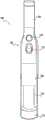
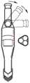
转到附图,图1至图4示出了根据本公开的实施例的手持式表面清洁装置100。如图所示,手持式表面清洁装置100包括本体102,该本体沿纵向轴线116从第一端部140延伸到第二端部142。手持式表面清洁装置100的本体102包括邻近第一端部140的手柄部分104、手柄部分之后是马达部分(或部段)106、过滤器部分108、集尘杯110和邻近第二端部142设置的喷嘴114。本体102可包括从第一端部140延伸到第二端部142的大致平坦且连续的表面180,以形成“接管”状装置。在一个实施例中,手柄部分104、马达部分106、过滤器部分108和喷嘴114可以形成为单个整体部件。在其他情况下,诸如喷嘴114和/或过滤器部分108等的部分可以是可移除的。Turning to the drawings, FIGS. 1-4 illustrate a handheld
如图所示,手持式表面清洁装置100的手柄部分104的轮廓被设计成在操作期间舒适地配合在使用者的手中。有利地,锥形区域146可以允许使用者的手和手指更舒适地抓握和操作手持式表面清洁装置100。手持式表面清洁装置100的本体102进一步包括打开/关闭按钮118和集尘杯释放按钮112。当手柄部分104由使用者的手保持时,打开/关闭按钮118和集尘杯释放按钮112可以由例如使用者的手的拇指致动。集尘杯释放按钮112可以被可滑动地接合,例如,被使用者的拇指移位,以解除锁定集尘杯110,这将在下面更详细地描述。在没有使用者提供的力的情况下,集尘杯释放按钮112可以被弹簧偏压以返回到后部位置。As shown, the
本体102的马达部段106可包括用于选择性地向设置在其中的马达126(参见图4)供电的电路(未示出)。马达126可以是DC马达或用于产生抽吸力的其他合适的马达。在一些实施例中,手持式表面清洁装置100可包括涡旋结构,因此所示实施例并不旨在限制本公开。马达126产生抽吸力以将空气吸入脏空气入口120。供应给马达126的电力的量可以变化以按比例调节抽吸功率的量。替代性地,打开/关闭按钮118可以简单地使恒定量的电力供应给马达126。The
继续地,集尘杯110可以被构造为接纳和储存经由脏空气入口120接纳的脏物和碎屑。如图所示,集尘杯110通过铰链149可旋转地联接到本体102,更具体地,联接到脏空气入口120的一部分,其中铰链149由相对于纵向轴线116大致横向地延伸穿过本体102的销形成。喷嘴114可以设置铰链149。在一些情况下,喷嘴114可以是可移动的。因此,当例如通过集尘杯释放按钮112释放集尘杯110时,集尘杯110可以沿第一旋转轴线旋转。例如,如图3所示,集尘杯110可以沿表示为D的大体方向旋转,并且在相对于本体102的纵向轴线116呈大约90度的角度处发生止动。集尘杯110的该位置可以被准确地称为打开取向、释放取向或处置取向。在打开取向上,开口148于是可用于允许灰尘和碎屑离开集尘杯110进入例如垃圾箱。因此,集尘杯110可以在例如如图1所示的锁定/闭合取向与如图3所示的打开/处置取向之间转换。当处于闭合取向时,集尘杯110通过开口148与过滤器部段108的过滤器流体连通。另一方面,当处于打开取向时,集尘杯110与过滤器部段108的过滤器断开流体连通并允许开口148释放/排出储存在集尘杯110内的灰尘和碎屑。Continuing, the
如下面进一步讨论的,集尘杯110可以包括清洁元件或搅拨元件,例如刷毛,该清洁元件或搅拨元件对过滤器部段108内的过滤器进行搅拨。对过滤器部段108内的过滤器的搅拨可以释放受困的/粘住的脏物和碎屑并且通常促进空气的流体连通的增加,以确保最小化堵塞或以其他方式防止堵塞减少抽吸功率。As discussed further below,
图4示出了沿着图1的线4-4截取的手持式表面清洁装置100的示例横截面视图。如图所示,本体102,特别是手柄部分104,限定了腔150,该腔可容纳一个或多个电源,例如电池。该腔可以包括电池保持部128或电池支架128,以便定位电池并将电池与相关的电触头(未示出)对准,从而将电池电联接到马达126。如上所论述的,手柄部分104提供锥形区域146,其中锥形区域146提供手柄部分104和马达部段106之间的过渡。FIG. 4 shows an example cross-sectional view of handheld
继续地,由本体102限定的腔150继续通过马达部段106。马达部段包括设置在腔150中的马达126。在马达部段之后,腔150继续通过过滤器部段108。于是,过滤器124可以设置在过滤器部段的腔150中。如图所示,过滤器124是锥形过滤器,但是其他过滤装置也在本公开的范围内。因此,腔150可以从手柄部分104的基部处的第一端部140延伸到途径脏空气入口120的第二端部。Continuing, the
与过滤器部段108相邻的集尘杯110联接到过滤器124。因此,集尘杯110可以通过开口148与过滤器部段108流体联接。挡网154(参见图6)可以覆盖开口148用于防止脏物和碎屑进入马达部段106,这将在下面进一步详细讨论。如进一步所示,脏空气入口120与集尘杯110流体连通,以接纳和储存脏物和碎屑。A
由柔性材料或弹性材料形成的阀体122可设置在集尘杯110和脏空气入口120之间。在没有由马达126提供的抽吸力的情况下,阀体122可保留在如图4所示的阀座部位置中。阀体122可以基于弹簧张力(例如,基于引入材料或其他合适的结构中的弯曲)被朝向脏空气入口120偏压。阀体122的座部位置可以形成密封,例如,阻止100%空气流的气密密封,或者形成限制集尘杯110的与脏空气入口120的开口对准的开口之中的至少80%空气流的部分气密密封,开口中的每一个通常以附图标记170示出。因此,当表面清洁装置100“闭合”(例如,不存在来自马达126的抽吸力)时,阀体122的就座位置可以防止灰尘和碎屑通过对准的开口170离开集尘杯110。阀体122可被构造成当由马达126产生的抽吸力将空气吸入脏空气入口并最终吸入集尘杯110时移位/弯曲进入集尘杯110的腔152中。A
在一个实施例中,当集尘杯110处于例如如图3所示的释放取向时,处于就座位置的阀体122例如基于弹簧力继续密封集尘杯110的腔,该弹簧力偏压阀体122离开集尘杯110以将其保持在一个或多个限定出集尘杯110的腔的表面上,从而确保灰尘和碎屑仅通过开口145离开集尘杯110。In one embodiment, when the
转到图5,其示出了适用于图1至图4的手持式表面清洁装置100的集尘杯的另一示例实施例。如图所示,集尘杯包括呈多个刷毛形式的搅拨构件155。刷毛可以由例如塑料或其他合适的刚性材料形成。当处于闭合位置时,诸如图6所示的,刷毛155可以设置成靠近手持式表面清洁装置100的本体102的上表面180。如图6的横截面视图所示,当集尘杯110绕轴线160旋转以从闭合取向转换到打开取向时,搅拨构件155与过滤器部段106的挡网154发生接触。注意,挡网154和过滤器124在本文中可统称为过滤器装置。一般来说,该接触“刮擦”挡网154,其可有利地移除或以其他方式移位粘附到挡网154的碎屑,以最小化或者减少马达、过滤器和脏空气入口120之间的抽吸功率的损失。Turning to FIG. 5 , another example embodiment of a dust cup suitable for use with the handheld
当将集尘杯110从打开取向转换到闭合取向时,可以实现相同的刮擦运动。为此,由使用者执行的集尘杯110的每次清洁操作可以导致两级清洁运动,其中第一级包括在释放集尘杯110时沿第一方向D1刮擦挡网154并且第二级包括当将集尘杯110转换到闭合位置时沿第二方向D2(参见图7)刮擦挡网154。在一些情况下,使用者可多次释放和闭合集尘杯110以使得两级清洁运动能够清除障碍物。The same scraping motion can be achieved when switching the
如图7所示,过滤器部段106可包括可移除的过滤器支架107,以允许更换过滤器124或者清洁过滤器124。如图所示,该实施例包括在移除可移除的过滤器支架107之前处于释放取向的集尘杯110。替代性地或另外地,整个过滤器支架107和过滤器124可以作为一体件更换以便于使用。As shown in FIG. 7 ,
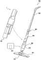
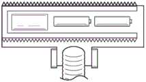
图8示出了真空吸尘器装置800的示例,该真空吸尘器装置被构造成可移除地联接到手持式表面清洁装置1。该手持式表面清洁装置1可以实现为图1的手持式表面清洁装置100,并且本公开不旨在限制这一点。如图所示,真空清洁装置800包括真空框架802(简称框架802)、可折叠接头804、手持式表面清洁器容纳部806、集尘杯容纳部808、可移除的集尘杯810和具有脏空气入口814的清洁头812。FIG. 8 shows an example of a
框架802限定手持式表面清洁器容纳部806或手持式容纳部,其中手持式容纳部被构造成牢固地保持手持式表面清洁装置1。当手持式表面清洁装置1被设置/安装在手持式容纳部806内时,脏空气入口120可与脏空气流道(未示出)对准并流体连通,该脏空气流道将脏空气入口814与集尘杯810流体地联接。因此,由手持式表面清洁装置1的马达产生的抽吸力可以用于将空气吸入脏空气入口814。从该脏空气入口,脏物和碎屑然后可以储存在集尘杯810(或第一集尘杯)中和/或手持式表面清洁装置1的集尘杯110(或第二集尘杯)中。The
在一些情况下,相对于单独使用集尘杯110,集尘杯810的存在有效地增加(例如,两倍或更多倍)了灰尘和碎屑的总储存量,尽管在一些实施例中可以唯一地使用集尘杯110。还如图所示,框架802包括可选的可折叠接头804,该接头允许框架802的手柄上部分平行于为了储存目的具有手持式容纳部806的下部分弯曲(另可参见图34A至图34C)。In some cases, the presence of
图9示出了具有门850的集尘杯810的示例,该门可以铰接到集尘杯810的本体840。在该示例中,可以按下按钮以释放门850并允许该门转动/旋转打开,而允许所储存的脏物和碎屑离开集尘杯810的本体840。FIG. 9 shows an example of a
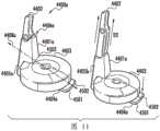
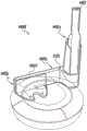
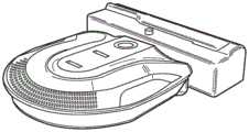
图10示出了插接系统4400的示例实施例,该插接系统包括插接部4401、手持式表面清洁装置4402和机器人真空吸尘器4403。在一个实施例中,手持式表面清洁装置4402被实现为图1的手持式表面清洁装置100或例如图21的手持式表面清洁装置1。如图所示,插接部4401包括至少部分地由基部4404限定的机器人真空吸尘器联接部段,其中基部4404被构造成可移除地联接到机器人真空吸尘器4403。基部4404可以进一步包括用于与机器人真空吸尘器4403电联接的电触头/端子,以用于再充电目的。FIG. 10 illustrates an example embodiment of a
插接部4401进一步包括手持式表面清洁装置联接部段4405,其也可以简称为接管联接部段。接管联接部段4405可包括接管容纳部4406和接管释放器4410(或接管释放踏板4410)。如图11的示例实施例中所示的,接管容纳部4406(或容纳部)可以是由接管联接部段4405的侧壁限定的凹部/开口。接管容纳部4406可以相对于插接部4401的纵向轴线4408大致垂直地延伸。接管容纳部4406可以被构造成至少部分地接纳手持式表面清洁装置4402。如图所示,接管容纳部4406包括使得手持式表面清洁装置4402的上表面4409能够与限定接管容纳部4406的表面4401齐平安装的深度。因此,手持式表面清洁装置4402在安装到接管容纳部4406中时可以相对地被隐藏,并且具有通常与接管联接部段4405的形状相对应的轮廓。The
将手持式表面清洁装置4402插入接管容纳部4406中可包括以第一角度(例如,大约80度)插入手持式表面清洁装置4402,其中手持式表面清洁装置4402的喷嘴用于偏压和接合弹簧加载机构(未示出)。一旦插入,手持式表面清洁装置4402可通过止动件(未示出)或其他合适的锁定机构锁定就位。Inserting the handheld
为了移除手持式表面清洁装置4402,提供在接管释放器4410上的使用者提供的力(例如,通过使用者的脚或手)使锁定机构断开接合并且可以允许弹簧加载机构将手持式表面清洁装置4402从储存位置转换到伸展位置/释放位置。如图所示,该转换可以包括手持式表面清洁装置4402围绕大致平行于纵向轴线4408延伸的第一旋转轴线4412旋转。在释放位置,使用者可以简单地抓握手持式表面清洁装置4402并且提供沿竖直远离接管容纳部4406的方向的力以使手持式表面清洁装置断开联接以便使用。To remove the hand-held
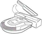
图11示出了根据本公开的插接系统4400a的另一示例实施例。图11的实施例还可以被确切地称为直立构型,在该直立构型,手持式表面清洁装置4402从插接部4401a竖直地延伸。更详细地,插接部4401a包括基部4404a和接管联接部段4405a。基部4404a包括释放按钮4501和4502。释放按钮4501和4502可以基于使用者提供的力(例如,来自使用者的脚)分别允许机器人真空吸尘器4403和手持式表面清洁装置4402断开联接。如图所示,释放按钮4501和4502可以至少部分地限定斜面,机器人真空吸尘器可以通过该斜面行进以联接到插接部4401a。FIG. 11 illustrates another example embodiment of a
接管联接部段4405a可以包括接管容纳部4406a,该接管容纳部被构造成至少部分地接纳手持式表面清洁装置4402。具体地,接管容纳部4406a可以包括细长的腔,该细长的腔具有可以与手持式表面清洁装置4402的纵向轴线大致垂直地延伸的纵向轴线。因此,当处于储存位置时,手持式表面清洁装置4402的手柄部段/区域可以至少部分地从接管容纳部4406a延伸。
接管联接部段4405a可以包括邻近机器人真空吸尘器联接部段的锥形部,以提供用于至少部分地接纳机器人真空吸尘器的凹部。因此,锥形部可以至少形成机器人真空吸尘器联接部段的一部分。当机器人真空吸尘器4403联接到基部4404a时,接管联接部段4405a的至少一部分4503可以延伸超过机器人真空吸尘器4403。有利地,这在机器人真空吸尘器处于储存位置、即联接到基部4404a时可以减少插接系统4400a的总占用面积。The
然后,使用者可以抓握手持式表面清洁装置4402的手柄部段/区域,并且通常沿着方向D2提供力以将手持式表面清洁装置与接管容纳部4406a断开联接。在一些情况下,使用者必须首先接合释放按钮4502以将手持式表面清洁装置4402从接管容纳部4406a解除锁定。另外,接管容纳部4406a可以包括弹簧加载机构,该弹簧加载机构响应于使用者为释放按钮4502提供的力而使手持式表面清洁装置4402沿方向D2向上行进,同时至少部分地保持在接管容纳部4406a内。方向D2可以相对于插接部4401a的纵向轴线4408a大致垂直地延伸。这可以有利地减少使用者必须向下伸手多远才能抓握手持式表面清洁装置4402的程度。The user can then grasp the handle section/region of the handheld
图12示出了根据本公开的处于直立构型的插接系统4400b的另一示例实施例。如图所示,该实施例大致类似于插接系统4400a的实施例,并且为了简洁起见,将不再重复其描述。然而,插接系统4400a包括没有锁定机构的接管容纳部4406b,而是可以利用摩擦配合或简单的重力。因此,手持式表面清洁装置4402可以在不致动例如释放按钮4502(图45)的释放器的情况下插入插接部4401b/从该插接部移除。FIG. 12 illustrates another example embodiment of a
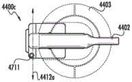
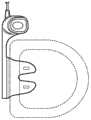
图13A至图13D示出了根据本公开的方面的插接系统4400c的另一示例实施例。如图所示,插接系统4400c包括插接部4401c、手持式表面清洁装置4402和机器人真空吸尘器4403。插接部4401c包括基部4404b,该基部限定机器人真空吸尘器联接部段。接管联接部段4401c包括通过铰链4702可旋转地联接到接管容纳部4407b的固定部分4703。因此,接管容纳部4407b可以围绕第二旋转轴线4412a在储存位置(图13/图13C/图13D)和释放位置(图13A)之间旋转,这在下面将更详细地论述。13A-13D illustrate another example embodiment of a
在图13A至图13D的实施例中,接管容纳部4407b可以至少部分地围绕手持式表面清洁装置4402。一般来讲,接管容纳部4407b可以形成基于摩擦配合连接、重力或者基于这两者将手持式表面清洁装置4402保持在固定位置的支架。In the embodiment of FIGS. 13A-13D , the
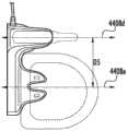
如图13A所示,接管容纳部4407b处于释放位置,在该释放位置,接管容纳部4407b相对于基部的纵向轴线4408b以约45±20度延伸。因此,使用者可以容易地向下伸手够到并抓握住手持式表面清洁装置4402。另一方面,当处于例如图13C所示的储存位置时,接管容纳部4407b大致平行于基部的纵向轴线4408b延伸。As shown in FIG. 13A, the
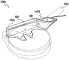
在一个实施例中,接管容纳部4407b可以通过铰链4702或通过允许围绕第二旋转轴线4412a旋转的其他合适的联接装置在储存位置和释放位置之间转换。插接部4401c可以包括用于使接管容纳部4407b在储存位置和释放位置之间旋转的机械机构(例如,齿轮、皮带驱动器或其他合适的机构)。固定部分4703可以包括接近传感器4711,例如红外(IR)传感器。接近传感器4711可以引起竖直IR场,使得当被使用者的手(或其他部分)破坏时,接管容纳部4407b可以自动旋转到释放位置,以使得能够容易地断开附接手持式表面清洁装置4402。释放位置还可以“暴露”或提供实现对机器人真空吸尘器4403的上表面进行控制的通路(参见图14A至图14C)。In one embodiment, the
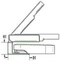
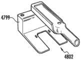
图14A至图14C额外详细地示出了图13A至图13D的实施例。如图所示,插接部4401c可以包括细长的腿部4802,该腿部从固定部段4799延伸一段距离D1,该距离D1是固定部段4799的高度H2的至少1.5倍。因此,在没有机器人真空吸尘器4403的情况下,有利地,细长的腿部4802可以支撑接管容纳部4407b(和手持式表面清洁装置4402)。14A-14C illustrate the embodiment of FIGS. 13A-13D in additional detail. As shown, the receptacle 4401c can include an
图15示出了根据本公开的方面的插接系统4400d的另一实施例。插接系统4400d类似于插接系统4400a(图11),为简洁起见,将不再复述其公开内容。如图所示,接管联接部段4405b包括IR传感器(或其他合适的接近传感器)和接管容纳部4407c,该接管容纳部具有齿/止动件(未示出)、升降机/伸展器机构。IR传感器可以发射在插接部4401d附近的IR光束。在IR光束被破坏(例如,通过使用者的手)的情况下,可以将信号发送到升降机/伸展器机构以使其沿竖直方向D3向上伸展。齿/止动件可以接合沿着手持式表面清洁装置4402的长度设置的引导部/轨道,以允许手持式表面清洁装置沿着相对直立的路径竖直地行进。在一个实施例中,这可以使手持式表面清洁装置4402上升六(6)英寸到八(8)英寸,但是其他配置也在本公开的范围内。IR传感器还可包括视觉指示器,例如LED,以将使用者的注意力吸引到传感器的位置。FIG. 15 illustrates another embodiment of a
如图15中进一步所示,接管联接部段4405b可以是锥形的(如侧面轮廓所示),以使接管容纳部4407c从相邻的壁偏移一距离D4。有利地,即使插接部4401d与壁齐平地设置,这也可以允许使用者更容易地伸手够到围绕手持式表面清洁装置4402的手柄,以抓握住手持式表面清洁装置。As further shown in FIG. 15, the
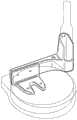
图16A至图16C共同示出了根据本公开的方面的插接系统4400e的另一实施例。如图所示,插接部4401e包括与插接部4401e的第一端部5001邻近的接管容纳部4407d。如图所示,接管容纳部4407d与插接部4401e一体形成为单个整体部件。然而,根据所需的构型,接管容纳部4407d和插接部4401e可以形成为单独的部件。接管容纳部4407d可包括曲线轮廓/形状,以增加美学吸引力并形成通常与手持式表面清洁装置4402的形状相对应的形状。16A-16C collectively illustrate another embodiment of a docking system 440Oe according to aspects of the present disclosure. As shown, the
如图所示,接管容纳部4407d具有固定的取向,在该固定的取向,设置在接管容纳部中的手持式表面清洁装置4402被保持在相对于限定插接部4401e的上表面5002为大约45度的角度。其他角度在本公开的范围内。图16A至图16C的实施例可以精确地称为并排式构型,其中接管容纳部4407d与机器人真空吸尘器的联接到插接部4401e的区域相邻(例如,侧向设置)。因此,当插入到接管容纳部4407d中时,手持式表面清洁装置4402包括纵向中心线4408d,该纵向中心线被设置成从与插接部4401e相切绘制的机器人真空吸尘器的中心线4408e水平地偏移一距离D5,其中距离D5至少等于机器人真空吸尘器的半径R1。As shown, the
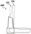
图17示出了根据本公开的方面的插接系统4400f的另一实施例。如图所示,实施例类似于图16A至图16C的插接系统4400e的实施例,因此为了简洁起见,将不再重复其描述。如图所示,插接部4401f包括接管联接部段4405c,该接管联接部段包括与机器人联接部段4420c处于并排构型的接管容纳部4407e。接管联接部段4405c还包括IR传感器5102(或其他合适的接近传感器)。响应于使用者破坏由IR传感器5102发射的IR光束,可以将信号发送到接管容纳部4407e。然后,提升和倾斜机构(未示出)可以接收信号并将手持式表面清洁装置4402从储存位置5105转换到释放位置5106。如图所示,转换到释放位置5106引起手持式真空装置4402首先沿着相对于机器人真空吸尘器的上表面的竖直路径行进(例如,远离机器人真空吸尘器),然后使手持式真空装置4402朝向机器人真空吸尘器“倾斜”,例如,相对于机器人真空吸尘器倾斜大约70±15度的角度。另一方面,转换到储存位置5105引起转换到释放位置5106的反向动作,例如,倾斜回到竖直方向,然后向下朝向机器人真空装置行进。FIG. 17 illustrates another embodiment of a
如果没有检测到使用者,例如,使用者离开插接部4401f,则提升和倾斜机构可以自动地将手持式表面清洁装置转换回到储存位置5105。有利地,这可以允许使用者将手持式表面清洁装置4402插入接管容纳部4407e中并且在接管容纳部4407e转换回到储存位置5105时仅简单地离开即可。The lift and tilt mechanism can automatically convert the handheld surface cleaning device back to the
以下另外的实施例和示例同样适用于前述公开内容。例如,图21的手持式表面清洁装置1可以在上文公开的各种实施例中使用并包括例如可以用于联接到机器人清洁装置以及手持式清洁装置的基部(参见图10至图20B)。The following additional embodiments and examples apply equally to the foregoing disclosure. For example, the handheld
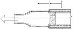
图21示出了根据本公开的实施例的手持式表面清洁装置1的透视图。如图所示,手持式表面清洁装置1包括联接到清洁头3的本体2。可选的柔性区域4(也可称为柔性导管)可将本体2联接到清洁头3,并且在清洁操作期间允许清洁头3相对于本体2旋转。脏空气通道14可以从由清洁头3提供的脏空气入口11穿过清洁头3和本体2延伸到集尘杯23(参见图22A和图22B),该集尘杯被设置为邻近本体的相对于清洁头3的远端部。因此,本体2和清洁头3可以流体连通,以通过脏空气通道接纳脏物和碎屑。Fig. 21 shows a perspective view of a handheld
本体2沿第一纵向轴线9从第一端部10-1延伸到第二端部10-2。本体2可具有例如如图所示的大致圆筒形的形状,但是其他形状(例如,矩形、正方形、不规则形状等等)和构型都在本公开的范围内。本体2可以由塑料或其他合适的刚性材料形成。本体2可以包括多个部件,或者可由一体部件形成。如图所示,本体2包括可移除的部件,以将集尘杯部分6与电力和马达部分8分开。The
本体2可以由表面5限定,该表面也可以称为手柄表面5。本体2的轮廓可以被设计成在使用期间舒适地配合在使用者的手中。因此,手柄表面5可以至少部分地围绕电力和马达部分8以及集尘杯部分6延伸。
本体2可以包括设置在第一端部10-1附近的电力和马达部分8,电力和马达部分之后是集尘杯部分6。如下面更详细地论述的,电力和马达部分8内的部件(例如,一个或多个马达和一个或多个例如电池的电源)可以与本体2的集尘杯部分6同轴地设置。由于电力和马达部分8设置在集尘杯部分6的前面(例如,上游),所以电力和马达部分8的部件可以共同限定一腔,该腔延伸穿过该电力和马达部分的部件,以允许沿着脏空气通道14行进的脏空气到达集尘杯部分6,以便储存。The
本体2可以包括靠近第二端部10-2设置的多个通气孔7,以允许已过滤的/清洁的空气离开本体2。多个通气孔7可靠近第二端部10-2设置,以确保使用者的手在操作期间不会无意中覆盖多个通气孔7。用于多个通气孔7的其他位置在本公开的范围内,并且图21中示出的示例不应被解释为是限制性的。The
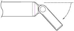
继续参照图21,清洁头3可以沿着第二纵向轴线15从第一端部12-1延伸到第二端部12-2。清洁头3可以与本体2由相同的材料形成,或者可以包括不同的材料。在一些情况下,清洁头3由可弯曲材料形成,例如,可以基于使用者提供的力弯曲/伸直的材料。在其他情况下,清洁头3由抵抗弯曲的相对刚性的材料形成。在其他情况下,清洁头3由多种材料形成。例如,邻近脏空气入口11的第一端部12-1可以由相对刚性的材料形成,且第二端部12-2可以由相对刚性的材料形成。With continued reference to FIG. 21 , the cleaning head 3 can extend along the second
在一些情况下,本体2的第一纵向轴线9可以相对于第二纵向轴线15大致平行,例如,出于储存目的、插接目的、或者当使用者希望清洁头3从本体2笔直延伸时。在其他情况下,如图所示,清洁头3的第二纵向轴线15可以相对于第一纵向轴线9以角度17延伸,该角度17在1度到180度之间、并且优选地在30至90度之间。In some cases, the first longitudinal axis 9 of the
如进一步所示的,脏空气入口11设置在第一端部12-1处。脏空气入口11可以限定具有宽度W1和高度H1的开口。例如,W1与H1的比率可以测量为约2:1、3:1、4:1、10:1、15:1,并包括它们之间的所有范围。总长度L1相对于宽度W1的比率可以测量为约1:1、1.25:1、1.5:1、2:1,并包括它们之间的所有范围。其他比率在本公开的范围内,并且所提供的示例不旨在是限制性的。脏空气入口11的宽度W1可以大于清洁头3的在第二端部12-2附近的宽度W2。因此,清洁头3可以从第一端部12-1朝向第二端12-2逐渐变细。然而,清洁头3可以不必需如图所示逐渐变细,并且可以包括沿纵向轴线15的大致连续的宽度。As further shown, the dirty air inlet 11 is provided at the first end 12-1. The dirty air inlet 11 may define an opening having a width W1 and a height H1. For example, the ratio of W1 to H1 may measure about 2:1, 3:1, 4:1, 10:1, 15:1 and include all ranges therebetween. The ratio of the total length L1 to the width W1 may measure about 1:1, 1.25:1, 1.5:1, 2:1 and include all ranges therebetween. Other ratios are within the scope of the disclosure, and the examples provided are not intended to be limiting. The width W1 of the dirty air inlet 11 may be greater than the width W2 of the cleaning head 3 near the second end 12 - 2 . Accordingly, the cleaning head 3 may taper from the first end 12-1 towards the second end 12-2. However, the cleaning head 3 may not necessarily taper as shown, and may comprise a generally continuous width along the
手持式表面清洁装置可进一步可选地包括设置在本体2和清洁头3之间的柔性区域4(或柔性导管)。具体地,柔性区域4的第一端部可以联接到清洁头3的第二端部12-2。柔性区域4的与第一端部相对的第二端部可以联接到本体2的第一端部10-1。柔性区域4可以包括至少限定了脏空气通道14的一部分的腔。The handheld surface cleaning device may further optionally include a flexible region 4 (or flexible conduit) disposed between the
柔性区域4可以由允许基于使用者提供的力进行弯曲的塑料或其他可弯曲的材料形成。柔性区域4可以被构造成在没有使用者提供的力的情况下返回到特定的静止状态。例如,柔性区域4可以返回到未弯曲状态,该未弯曲状态使本体2的第一纵向轴线9和清洁头3的第二纵向轴线15大致平行地延伸。在其他情况下,柔性区域4可以被构造成例如经由夹子或其他机械保持特征保持在弯曲位置,直到使用者提供力以将清洁头相对于本体2转换到不同的位置。The flexible region 4 may be formed from plastic or other bendable material that allows bending based on a force provided by the user. The flexible area 4 may be configured to return to a specific rest state in the absence of force provided by the user. For example, the flexible region 4 may be returned to an unbent state such that the first longitudinal axis 9 of the
在任何情况下,柔性区域4允许清洁头3相对于本体2旋转。在一些情况下,柔性区域4可以允许测量介于0度到180度之间的角度17,如上文所论述的。优选地,柔性区域4允许达到90度的旋转。In any case, the flexible area 4 allows the cleaning head 3 to rotate relative to the
在一些情况下,清洁头3相对于本体2的旋转可以使手持式表面清洁装置接通。例如,当使用者希望清洁特定表面时,使用者可以简单地通过提供使得清洁头3接合表面并引起柔性区域4的弯曲的力来自动接通手持式表面清洁装置1。响应于柔性区域4的弯曲,手持式表面清洁装置1可以向马达供电以引入沿着脏空气通道14的抽吸力。同样,没有使用者提供的力可能导致手持式表面清洁装置1切断。In some cases, rotation of cleaning head 3 relative to
替代性地,或者除了上面论述的自动接通特征之外,本体2可以包括按钮或其他合适的控制器(未示出),以允许手持式表面装置1的手动接通/切断。Alternatively, or in addition to the auto-on feature discussed above, the
注意,柔性区域4是可选的。例如,本体2可以简单地直接联接到清洁头3。替代性地,柔性区域4可以用基于使用者提供的力不会弯曲的刚性部分(或刚性导管)代替。Note that flex area 4 is optional. For example, the
在任何这样的情况下,本体2和/或清洁头3可以可移除地联接到柔性区域4。因此,使用者可以将本体2和/或清洁头3从柔性区域4移除,例如以疏通脏空气通道14或者附接不同类型的清洁头3,例如配置有刷毛的清洁头。In any such case, the
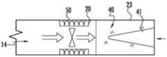
转到图22A,根据本公开的实施例,本体2被示出为与清洁头3和柔性区域4分离。本体2以高度简化的形式示出,并且其他部件可以设置在本体2内。如图所示,本体限定腔19。本体2进一步包括设置在腔19内的马达20、电源22和集尘杯23。马达20、电源22和集尘杯23中的每一个可以包括与纵向轴线9大致平行的纵向轴线。因此,马达20、电源22和集尘杯23可以同轴地设置在腔19内。如下文所论述的,这种同轴布置允许马达20、电源22和集尘杯23使它们各自的腔对齐以共同形成单个脏空气通道,例如脏空气通道14。注意,根据所需的构型,同轴布置可以形成多个脏空气通道,并且本公开不应该被解释为限于单个通道。Turning to FIG. 22A ,
马达20可以包括例如无刷DC马达,但是其他类型的马达也在本公开的范围内。马达20可以经由充电电路电联接到电源22和/或AC干线,如下文进一步论述的。马达20可以包括腔52(参见图23C),以允许脏空气通道14穿过该腔延伸。马达20可以包括将空气流/抽吸力引向集尘杯23的叶轮/风扇50。
图23C和图23B更详细地示出了根据本公开的实施例的马达20。如图所示,马达20可以包括设置在腔52中的内置风扇50。马达20可进一步可选地包括沿着侧壁53的开口/通气孔51,以调节空气流。23C and 23B illustrate
返回图22A,电源22可以包括多个电池单元29。在一个实施例中,电池单元中的每一个是锂离子电池单元,但是其他类型的电池单元也在本公开的范围内。如图23A的电源22A所示,多个电池单元29中的每一个可以形成环形结构。环形结构可以包括延伸穿过其中的腔32。在环形结构中,电池单元中的每一个可以具有各自的纵向轴线,当电源22A设置在本体2中时,电池单元的该纵向轴线与本体2的纵向轴线9大致平行。图23B示出了配置为环形电容器的另一示例电源22B。环形电容器还可以包括延伸穿过其中的腔33。在任何这样的情况下,电源22可以基于相关的腔至少部分地限定脏空气通道14。因此,当电源22和腔52设置在本体2的腔19内时,电源22的腔(例如,腔32或33)可以与马达的腔52对准。Returning to FIG. 22A , the power supply 22 may include a plurality of
返回图22A,电源22可以通过相关的充电电路(未示出)充电。充电电路可以包括例如感应线圈以接收电荷,从而为电源22充电。替代性地或者另外地,充电电路可以包括端子或其他合适的互连部(例如,USB-C端口),以例如为了充电而联接到基部/插接站。充电电路还可以允许来自干线的电力直接由手持式表面清洁装置1使用,同时还对电源22充电。Returning to Figure 22A, the power source 22 may be charged by an associated charging circuit (not shown). The charging circuit may include, for example, an induction coil to receive electrical charge to charge the power source 22 . Alternatively or in addition, the charging circuit may include terminals or other suitable interconnects (eg, USB-C ports) to couple to the base/docking station, eg, for charging. The charging circuit may also allow power from the mains to be used directly by the handheld
图22B示出了与图22A的本体2的构型具有大致相似构型的本体2’,因此前面的描述同样适用于本体2’,并且为了简洁起见,将不再复述。然而,本体2’包括设置在马达20之前的电源22。因此,本体2’包括靠近本体2的第一端部10-1设置的电源22,电源之后是马达20,然后是集尘杯23。Figure 22B shows a body 2' having a substantially similar configuration to that of the
图22A的本体2和图22B的本体2’可以包括多个电源22和/或多个马达20,多个电源22和/或多个马达20设置在腔19内并且在该腔内对准以形成脏空气通道14。因此,尽管上述示例示出了单个马达和电源,但是本公开并不限于此。同样地,尽管示出的每个马达、电源和集尘杯具有基本上圆筒形的形状,但是本公开不限于此。其他形状和构型在本公开的范围内。The
转到如图23C到图23D,集尘杯23可以被构造成接纳和储存从脏空气通道14接收的灰尘和碎屑。集尘杯可以限定出腔40以储存灰尘和碎屑。集尘杯进一步可以包括静电荷蓄电池(statically-charged accumulator)41,以帮助吸引和捕获灰尘和碎屑。在一些情况下,静电荷蓄电池41由自然趋于保持静电荷的材料形成。替代性地或另外地,静电荷蓄电池41可以经由例如电源22供以能量。Turning to FIGS. 23C-23D , the
图24A至图24C示出了根据本公开的另外的示例实施例。如图24B所示,手持式表面清洁装置可以插接到基部中以用于再充电目的。24A-24C illustrate additional example embodiments according to the present disclosure. As shown in Figure 24B, the handheld surface cleaning device can be plugged into the base for recharging purposes.
图25示出了根据本公开的示例手持式表面清洁装置。图26A示出了根据本公开的实施例的图25的手持式表面清洁装置的横截面视图。图26B以分离的方式示出了根据本公开的实施例的图25的手持式表面清洁装置的示例清洁头。图26C以分离的方式示出了根据本公开的实施例的图25的手持式表面清洁装置的示例手柄。25 illustrates an example handheld surface cleaning device according to the present disclosure. 26A illustrates a cross-sectional view of the handheld surface cleaning device of FIG. 25, according to an embodiment of the disclosure. 26B illustrates an example cleaning head of the handheld surface cleaning device of FIG. 25 in isolation, according to an embodiment of the disclosure. 26C illustrates an example handle of the handheld surface cleaning device of FIG. 25 in isolation, according to an embodiment of the disclosure.
图27示出了根据本公开的另一示例手持式表面清洁装置。如图27所示,手柄部分可以相对于本体旋转以转换/铰接到一个或多个位置。电池可以设置在手柄部分中,这例如在沿着A-A截取的横截面中示出。这种布置可以允许手柄部分在其整个长度上具有相对小的形状因子。27 illustrates another example handheld surface cleaning device according to the present disclosure. As shown in Figure 27, the handle portion can be rotated relative to the body to convert/hinge to one or more positions. A battery may be provided in the handle portion, as shown for example in cross-section along A-A. This arrangement may allow the handle portion to have a relatively small form factor over its entire length.
图28A至图28C示出了根据本公开的实施例的表面清洁装置的另外的示例实施例。28A-28C illustrate additional example embodiments of surface cleaning devices according to embodiments of the present disclosure.
图29A至图29H示出了根据本公开的实施例的表面清洁装置的另外的示例实施例。如图所示,根据本公开的手持式表面清洁装置可以包括用于在集尘杯清空过程中擦拭/移除灰尘的结构。29A-29H illustrate additional example embodiments of surface cleaning apparatus according to embodiments of the present disclosure. As shown, a handheld surface cleaning device according to the present disclosure may include structure for wiping/removing dust during emptying of the dust cup.
图30A至图30C示出了根据本公开的实施例的表面清洁装置的另外的示例实施例。如图所示,可以延长集尘杯以增加储存容量。30A-30C illustrate additional example embodiments of surface cleaning apparatus according to embodiments of the present disclosure. As shown, the dust cup can be extended to increase storage capacity.
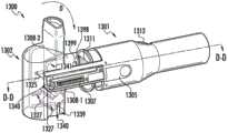
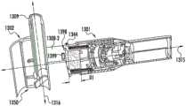
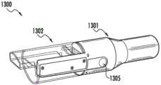
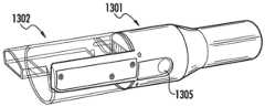
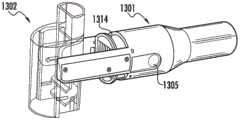
参照图31A至图31D,示出了根据本公开的实施例的示例表面清洁装置1300。如图所示,表面清洁装置1300包括本体1301和联接到本体1301的第一端部1319的集尘杯1302。注意,上文参照图1至图20B和图21至图30C示出和描述的方面和实施例同样适用于表面清洁装置1300,并且为了简洁起见,将不再复述。Referring to FIGS. 31A-31D , an example
如本文通常所提到的,术语“闭合位置”和“插接位置”可以互换使用,并且指的是集尘杯1302相对于本体1301的位置,在该位置,集尘杯1302联接到本体1301并且与本体1301流体连通,更具体地说,该集尘杯与设置在本体1301的腔内的产生抽吸力的马达1322流体连通以将脏物和碎屑吸入集尘杯1302。在一些情况下,闭合位置可以使集尘杯1302具有与本体1301的纵向轴线大致平行延伸的纵向轴线,例如图31A所示的。As generally referred to herein, the terms "closed position" and "docked position" are used interchangeably and refer to the position of the
相反,术语“打开位置”或“清空位置”可以互换使用,并且指的是集尘杯1302相对于本体1301的位置,在该位置,集尘杯1302相对于本体1301大致垂直地成角度,以允许清空集尘杯。集尘杯1302可以可旋转地/可枢转地联接到本体1301,以允许集尘杯1302转换到打开位置。该转换可以由例如设置在本体1301上的按钮1305启动,这将在下面更详细地论述。因此,当处于打开位置时,集尘杯可以与马达1322流体地断开联接,同时保持可枢转地/可旋转地联接到壳体。Rather, the terms "open position" or "emptying position" are used interchangeably and refer to the position of the
如下面更详细地论述的,集尘杯1302可以是弹簧加载的,以将该集尘杯“弹开(spring)”/推动到打开位置。本体1301可以设置止动部,例如侧壁1340(图31B)或其他表面特征,以在集尘杯1302由于弹簧张力的释放而旋转时接合集尘杯1302。然后,与止动部的接合可以使集尘杯1302突然停止旋转运动,伴随着的是有利地移除储存在集尘杯1302内的脏物和碎屑的冲击。然后可以利用重力来使移除的脏物和碎屑从集尘杯的位于与用于接收脏空气的入口相对的端部处的开口清空。然后,弹簧偏压可以将集尘杯1302保持在打开位置,直到使用者希望将集尘杯1302转换回闭合位置。因此,使用者可以简单地使手持式表面清洁装置1300在垃圾桶的口上方倾斜,并且例如通过按钮1305的致动将集尘杯1302转换到打开位置以清空集尘杯1302。As discussed in more detail below, the
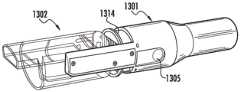
另外,并且根据一个实施例,过滤器装置1314可以至少部分地设置在本体1301内。过滤器装置1314也可以是弹簧加载的并且向前“弹开”(参见图31B和图31D)以至少部分地从本体1301延伸并停止在预定距离D1处。在该实施例中,过滤器装置1314可以从本体1301离开行进到距离D1(在集尘杯1302旋转远离过滤器装置1314之后),然后遇到止动部,例如,搭接部、捕获部(catch)或设置在本体1301内部或外部的其他突起,例如突起1398(参见图31B)。然后,弹簧偏压可以将过滤器装置1314保持在延伸位置,直到集尘杯1302在过滤器装置1314例如基于使用者提供的力而返回到闭合位置时使过滤器装置1314移位。Additionally, and according to one embodiment, a
因此,表面清洁装置1300可以被准确地描述为具有基于使用者提供的单个动作的多阶段(或多级)打开顺序,其中响应于使用者提供的单个动作(例如,按钮按下),集尘杯首先(纵向地)向前脱出/弹开/推出,然后旋转到竖直/直立位置,随后过滤器装置在集尘杯转换的同时脱出/弹出或在集尘杯转换后不久脱出/弹出(例如,基于过滤器装置1314的弹簧,该弹簧具有与和集尘杯1302相关联的弹簧不同的弹簧常数/构型)。注意,集尘杯1302可以加重以引起直立位置(参见图31B)。替代性地或另外地,可以基于由本体1301提供的引起旋转发生的轨道使集尘杯1302进入直立位置。注意,集尘杯1302可以被配置有类似于图5的集尘杯110的搅拨装置的搅拨装置,例如刷毛,上文公开的实施例同样适用于图31A至图31D的手持式表面清洁装置。Thus, the
继续参照图31A至图31D,马达1322设置在本体1301内并产生抽吸力以在使用期间经由脏空气通道1330(参见图31C)将脏空气吸入入口1309(或喷嘴)。当集尘杯1302处于例如图13A中所示的闭合位置时,集尘杯1302、更具体地为脏空气通道1330可以与马达1322流体连通。设置在本体1301和集尘杯1302之间的过滤器1311可以防止/减少灰尘和碎屑进入本体1301并最终堵塞马达1322。然后在表面清洁装置1300的操作期间可以将灰尘和碎屑储存在集尘杯1302的腔内的灰尘储存区域1331(图31C)中。With continued reference to FIGS. 31A-31D , a
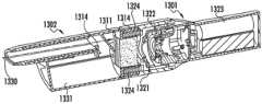
在一个实施例中,当基于集尘杯1302相对于本体1301的旋转而处于打开位置时,集尘杯1302可以与马达1322的抽吸断开联接。例如,如图31B所示,集尘杯1302的端部可以与本体1301断开联接并且旋转以使集尘杯1302相对于本体1301大致横向地成角度。如图31D所示,集尘杯1302的打开位置可以使得集尘杯1302具有纵向轴线1316,该纵向轴线1316相对于本体的纵向轴线1315大致是横向的。注意,集尘杯1302相对于本体1301延伸所按照的角度可以变化,例如从15度到180度,并且优选地从15度到90度,这取决于期望的构型。In one embodiment, the
在一个实施例中,本体1301可以由塑料、金属和/或任何其他合适的刚性材料形成。本体1301可以由材料的一体部件形成,或者由多个部件形成。In one embodiment,
本体1301可以由沿着纵向轴线1315从第一端部1319(可以被称为灰尘联接端部1319)延伸到第二端部1320的壁限定。该壁可以由表面1306限定,其中表面1306提供手柄部分或手柄,该手柄部分或手柄可在表面清洁装置1300的操作期间被舒适地抓握在使用者的手中。
本体1301进一步包括按钮1305,用于使集尘杯1302从闭合位置(例如,如图31A所示的)转换到打开位置(例如,如图31B所示的)。注意,按钮1305不必须受限于机械按钮,其中使用者按压该按钮以使表面清洁装置1300从闭合位置转换到打开位置。例如,按钮1305还可以是任何其他合适的使用者输入装置,诸如滑块按钮、电容触摸式按钮和围绕本体1301的直径延伸的可旋转环。The
本体1301可以限定腔1321(图31C)。腔可以包括设置在其中的过滤器装置1314、马达1322和电源1323。马达1322可以包括例如无刷DC马达,但是其他类型的马达也在本公开的范围内。马达1322可以电联接到电源1323并且产生用于将脏物和碎屑吸入到集尘杯1302中的抽吸力。The
集尘杯1302可以包括塑料、金属或任何其他合适的刚性材料。集尘杯1302可以由沿着纵向轴线1316(图31D)从第一端部1309(或喷嘴)延伸到第二端部1350(抽吸联接端部或抽吸联接部段)的一个或多个壁限定。集尘杯1302可以进一步限定出腔,该腔具有至少部分地延伸穿过其中的脏空气通道1330,其中脏空气通道与纵向轴线1316大致平行地延伸。集尘杯1302进一步包括在腔内的灰尘储存区域1331,以接纳和储存脏物和碎屑。围绕灰尘储存区域1331的壁可以是透光的,例如允许80%或更多的入射可见波长,以允许使用者通过壁可视地检查储存在灰尘储存区域中的脏物和碎屑的当前量。注意,当集尘杯1302在打开位置直立/竖直定向时,抽吸联接端部1350还设置用于清空脏物和碎屑的开口。The
过滤器装置1314包括通常与本体1301的形状相对应的圆筒形壳体。过滤器装置1314的其他形状和构型也在本公开的范围内。过滤器装置1314可以包括一个或多个过滤器,例如图31C中所示的褶皱过滤器1311。一个或多个过滤器可包括例如聚酯材料、PTFE、玻璃纤维或任何其他合适的过滤器材料。一个或多个过滤器可包括滤筒本体,以便于移除和更换过滤器。
过滤器装置1314可以进一步包括弹簧1324,以将过滤器装置1314偏压离开本体1301并朝向集尘杯1302。当集尘杯1302处于如图31A和图31C所示的闭合位置时,弹簧1324可以基于集尘杯1302被压缩,以使过滤器装置1314朝向本体1301的腔1321移位。注意,弹簧1324可以包括或多或少的弹簧,例如单个弹簧,这取决于期望的构型。The
继续地,臂1308-1和1308-2(或臂部分)可以沿着纵向轴线1315从本体1301延伸。臂1308-1、1308-2可以与本体1301一体地形成为单个整体部件,或者可以由多个部件形成。在一个实施例中,臂1308-1和1308-2可以由与本体1301的材料相同的材料形成,例如,由塑料或其他合适的刚性材料形成。在一些情况下,臂1308-1和1308-2可以由与本体1301的材料不同的材料形成。例如,臂1308-1和1308-2可以至少部分地由金属或者金属合金形成,以加强该臂。Continuing, arms 1308 - 1 and 1308 - 2 (or arm portions) can extend from
臂1308-1和1308-2可以各自枢转地联接到集尘杯1302,以允许沿着通常表示为D(图31B)的方向/路径进行旋转运动。因此,集尘杯1302可基于旋转轴线1325相对于臂1308-1和1308-2进行枢转/旋转,其中旋转轴线1325大致垂直于纵向轴线1315。Arms 1308-1 and 1308-2 may each be pivotally coupled to
臂1308-1和1308-2可以进一步限定出腔。由臂1308-1和1308-2限定的腔可以包括弹簧1307。弹簧1307中的每一个可以例如通过将力提供到集尘杯承载件1326或提供到联接到集尘杯1302的其他机构上而将集尘杯1302偏压离开本体1301。集尘杯承载件1326可以与集尘杯1302一体地形成,即形成为单个整体部件,或者可以由多个部件形成。集尘杯承载件1326被构造为沿着由臂1308-1和1308-2提供的轨道/引导部纵向地行进。因此,集尘杯承载件1326可用于使集尘杯1302从闭合位置转换/移位到打开位置。Arms 1308-1 and 1308-2 may further define a cavity. The cavity defined by arms 1308 - 1 and 1308 - 2 may include
为了将集尘杯承载件1326牢固地保持在闭合位置,并且通过延伸将集尘杯1302保持在闭合位置,止动件1399(图31B)或其他合适的锁定机构可以从臂1308-1和1308-2的表面延伸。止动件1399可以被弹簧偏压并且被构造成接合集尘杯1302的相应表面特征(例如,捕获部/凹部1327)。因此,当集尘杯1302例如基于使用者提供的力与过滤器装置1314对准并且压靠过滤器装置1314时,止动件1399可以与集尘杯1302的捕获部1327接合,以将集尘杯1302相对于本体1301牢固地保持就位。In order to securely hold the
为了释放集尘杯1302并将集尘杯转换到打开位置,使用者可以按压按钮1305。按压按钮1305可以包括使用拇指和食指对设置在本体1301的相对侧面上的按钮进行捏压动作。作为响应,按钮1305可以机械地致动止动件1399以使其与集尘杯1302的捕获部断开接合。替代性地,按钮1305可以提供可以用于例如引起马达或其他机械致动器与止动件1399断开接合的电信号。To release the
因此,在任何情况下,按钮1305可以允许使用者使集尘杯1302转换到打开位置以清空集尘杯并使灰尘和碎屑离开过滤器。集尘杯1302可以包括限定出侧壁1341的凹入表面1339(参见图31B)或凹入区域1339,其中侧壁1341相对于表面1339大致垂直地延伸。侧壁1341可以被构造成接合臂1308-1和1308-2的止动表面1340以防止集尘杯1302超过预定限制(例如90度)的旋转运动。集尘杯1302遇到止动表面1340的冲击可有利地移除集尘杯1302内的脏物和碎屑。Thus, in any event, the
同样地,如图31D所示,过滤器装置1314可包括突起/捕获部/表面1344以接合本体1301的相应止动部/突起1398。注意,集尘杯1302可以包括凹入区域/引导部1340以接合突起1398。因此,当集尘杯1302转换回到闭合位置时,突起1398可用于对准并引导集尘杯1302与本体1301对准。Likewise, as shown in FIG. 31D , the
在一个实施例中,表面清洁装置1300可以用单手保持并且用同一只手从闭合位置转换到打开位置。In one embodiment, the
图32A至图32D共同示出了从闭合位置转换到打开位置的手持式表面清洁装置1300。具体地,图32A示出了根据本公开的实施例的处于闭合位置的手持式表面清洁装置1300,在该闭合位置,集尘杯1302与设置在本体1301中的马达流体连通。32A-32D collectively illustrate the handheld
图32B示出了根据本公开的实施例的在使用者按下本体1301的两侧上的按钮1305中的一个或两个之后的手持式表面清洁装置1300。响应于按钮1305被按下,止动件1399(图31B)可以从集尘杯1302断开接合。同样,并且如图32C所示,集尘杯1302和过滤器装置1314可以纵向地行进远离本体1301。在一些情况下,在集尘杯1302的旋转运动和过滤器装置1314的运动之间可能存在短暂的停顿,这取决于所需的构型。Figure 32B shows the handheld
如图32D所示,集尘杯1302然后可以相对于本体1301旋转/枢转并且停止在将集尘杯1302保持在相对于本体1301大致横向的取向的位置。集尘杯1302可以基于由臂1308-1和1308-2提供的轨道/引导部枢转。替代性地或另外地,可以对集尘杯1302加重量以使集尘杯自然地倾向于朝向竖直/直立取向。As shown in FIG. 32D , the
集尘杯1302可以至少部分地基于设置在第一臂1308-1和第二臂1308-2中的弹簧1307(参见图31B)保持在该位置。同样地,过滤器装置1314可以基于来自弹簧1324的弹簧偏压而保持在伸出位置。因此,使用者然后可以摇动手持式表面清洁装置1300以使灰尘和碎屑从集尘杯1302中清空。为了使集尘杯1302进入闭合位置以供进一步使用,使用者可以简单地将集尘杯1302旋转成与本体1301对准,然后将集尘杯1302朝向本体1301滑动以移位过滤器装置1314并基于与集尘杯1302的侧壁特征(例如凹部1327)接合的止动件1399而“锁定”到闭合位置。The
图33示出了根据本公开的实施例的表面清洁装置的另一示例实施例。FIG. 33 illustrates another example embodiment of a surface cleaning device according to an embodiment of the present disclosure.
图34A至图34C示出了根据本公开的实施例的表面清洁装置的另外的示例实施例。注意,图34A至图34C所示的示例方面同样适用于图8所示的实施例。34A-34C illustrate additional example embodiments of surface cleaning devices according to embodiments of the present disclosure. Note that the exemplary aspects shown in FIGS. 34A-34C apply equally to the embodiment shown in FIG. 8 .
图35A至图35B示出了根据本公开的实施例的表面清洁装置的另外的示例实施例。35A-35B illustrate additional example embodiments of surface cleaning devices according to embodiments of the present disclosure.
图36A至图36B示出了根据本公开的实施例的表面清洁装置的另一示例实施例。36A-36B illustrate another example embodiment of a surface cleaning device according to an embodiment of the present disclosure.
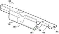
图37至图45示出了手持式表面清洁装置1900的另一示例实施例,该手持式表面清洁装置具有本体1901,该本体包括手柄1907、可延伸的缝隙工具1902、旋风分离器组件1904和电联接到至少一个电池1905的马达1912。电池1905可以储存在手柄1907中。如图所示,旋风分离器组件1904包括流体联接到缝隙工具1902的入口1906、涡流探测器1908、收集区域1910和过滤器1914。在操作中,空气从缝隙工具入口1916抽取并进入旋风分离器组件1904。空气可以包括例如在清洁操作期间收集的碎屑。携带在空气中的碎屑可以收集在旋风分离器组件1904内(例如,在收集区域1910内)。37-45 illustrate another example embodiment of a handheld
当在旋风分离器组件1904内收集足够量的碎屑时,操作者可通过使门1918打开来清空碎屑。一旦门1918打开,碎屑就可以离开旋风分离器组件1904(例如,由于重力)。操作者可以通过致动按钮(或触发器)1920来打开门1918。在一些情况下,按钮1920的致动可以导致推杆1922的移动。当推杆1922在第一位置和第二位置之间移动时,推杆1922可以接合将门1918保持在闭合位置的闩锁1924。如图所示,当闩锁1924被移动与门1918断开接合时,门1918绕轴线1926旋转。When a sufficient amount of debris has collected within
一旦被释放,操作者可以通过将门1918推回到与闩锁1924进行接合来使门1918重新闭合。另外地或替代性地,使用者可以第二次致动按钮1920(或致动不同的按钮或触发器),以使门1918闭合。在一些情况下,闩锁1924可包括偏压构件(例如,弹簧),该偏压构件驱使闩锁1924朝向接合位置(例如,闩锁1924能够接合门1918的位置)。Once released, the operator can reclose the
缝隙工具1902可以从第一位置延伸到第二位置。例如,操作者可手动抓住缝隙工具1902并拉动(或推动)缝隙工具1902以使缝隙工具1902在第一位置和第二位置之间转换。另外地或替代性地,缝隙工具1902可以响应于按钮(或触发器)的致动而在第一位置和第二位置之间转换。The
还如图所示,旋风分离器组件1904的至少一部分可以可移除地联接到手持式表面清洁装置1900的本体1901。例如,旋风分离器组件1904的移除可允许使用者对过滤器1914进行清洁和/或更换过滤器1914。作为另一个示例,在一些情况下,涡流探测器1908可以是可移除的。如图所示,可以设置脚趾状特征(toe in feature)1917以将旋风分离器组件1904联接到本体1901。As also shown, at least a portion of the
在一些情况下,手持式表面清洁装置1900可以用在机器人真空吸尘器系统中。例如,手持式表面清洁装置1900可用于从机器人真空吸尘器移除碎屑。In some cases, handheld
根据一个方面,公开了一种手持式表面清洁装置。该手持式表面清洁装置包括从第一端部延伸到第二端部的本体、由本体限定并且邻近第一端部的手柄部分、由本体限定并且邻近第二端部的具有脏空气入口的喷嘴、用于产生抽吸力并将空气吸入脏空气入口的马达、以及用于接纳和储存灰尘和碎屑的集尘杯,该集尘杯被可旋转地联接到手持式表面清洁装置的本体并且被构造成在闭合取向和释放取向之间转换,在闭合取向,使集尘杯与脏空气入口和马达流体联接,在释放取向,使集尘杯与脏空气入口和马达断开联接,以使储存在集尘杯中的脏物和碎屑从集尘杯的开口离开。According to one aspect, a handheld surface cleaning device is disclosed. The handheld surface cleaning device includes a body extending from a first end to a second end, a handle portion defined by the body and adjacent the first end, a nozzle having a dirty air inlet defined by the body and adjacent the second end , a motor for generating suction and drawing air into the dirty air inlet, and a dust cup for receiving and storing dust and debris, the dust cup being rotatably coupled to the body of the handheld surface cleaning device and is configured to switch between a closed orientation in which the dust cup is fluidly coupled with the dirty air inlet and the motor, and a released orientation in which the dust cup is disconnected from the dirty air inlet and the motor so that Dirt and debris stored in the dust cup exit through the opening of the dust cup.
根据另一方面,公开了一种插接系统。该插接系统包括具有机器人真空联接部段的插接部,并包括手持式表面清洁装置,该手持式表面清洁装置包括从第一端部延伸到第二端部的本体、由本体限定并且邻近第一端部的手柄部分、由本体限定并且邻近第二端部的具有脏空气入口的喷嘴、用于产生抽吸力并将空气吸入脏空气入口的马达、以及用于接纳和储存灰尘和碎屑的集尘杯,该集尘杯可旋转地联接到手持式表面清洁装置的本体并且被构造成在闭合取向和释放取向之间转换,在该闭合取向,使集尘杯与脏空气入口和马达流体地联接,在该释放取向,使集尘杯与脏空气入口和马达断开联接,以允许储存在集尘杯中的脏物和碎屑从集尘杯的开口离开,该插接系统还包括由插接部限定的容纳部,以接纳手持式表面清洁装置的第一端部和联接到手持式表面清洁装置的第一端部并使得限定手柄部分的第二端部远离插接部延伸。According to another aspect, a docking system is disclosed. The docking system includes a docking section having a robotic vacuum coupling section, and includes a handheld surface cleaning device including a body extending from a first end to a second end, defined by the body and adjacent to the A handle portion at the first end, a nozzle with a dirty air inlet defined by the body and adjacent to the second end, a motor for generating suction and drawing air into the dirty air inlet, and for receiving and storing dust and debris A dust cup for crumbs, the dust cup is rotatably coupled to the body of the handheld surface cleaning device and is configured to switch between a closed orientation and a released orientation in which the dust cup is in contact with the dirty air inlet and The motor is fluidly coupled, and in the released orientation, the dust cup is decoupled from the dirty air inlet and the motor to allow dirt and debris stored in the dust cup to escape from the opening of the dust cup, the plug-in system Also comprising a receptacle defined by the receptacle to receive and couple to the first end of the handheld surface cleaning device and to place the second end defining the handle portion away from the receptacle extend.
虽然本文已经描述了本公开的原理,但是本领域技术人员应当理解,该描述仅通过示例的方式作出,而不是作为对本公开范围的限制。除了本文所示和所述的示例性实施例之外,其他实施例也在本公开的范围内。本领域技术人员将理解,表面清洁装置可以体现本文所包含的特征中的任何一个或多个,并且该特征可以以任何特定组合或子组合使用。由本领域普通技术人员所作的修改和替换被认为是在本公开的范围内,本公开的范围只受权利要求的限制。While the principles of the disclosure have been described herein, those skilled in the art should understand that this description has been made by way of example only, and not as a limitation to the scope of the disclosure. Other embodiments in addition to the exemplary embodiments shown and described herein are also within the scope of the present disclosure. Those skilled in the art will appreciate that a surface cleaning device may embody any one or more of the features contained herein, and that the features may be used in any particular combination or subcombination. Modifications and substitutions by those of ordinary skill in the art are considered to be within the scope of the present disclosure, which is limited only by the claims.
Claims (64)
Translated fromChinesePriority Applications (1)
| Application Number | Priority Date | Filing Date | Title |
|---|---|---|---|
| CN202010302794.2ACN111466820B (en) | 2017-09-22 | 2018-09-25 | Handheld Surface Cleaning Devices |
Applications Claiming Priority (10)
| Application Number | Priority Date | Filing Date | Title |
|---|---|---|---|
| US201762561851P | 2017-09-22 | 2017-09-22 | |
| US62/561,851 | 2017-09-22 | ||
| US201762585320P | 2017-11-13 | 2017-11-13 | |
| US62/585,320 | 2017-11-13 | ||
| US201862616908P | 2018-01-12 | 2018-01-12 | |
| US62/616,908 | 2018-01-12 | ||
| US201862619309P | 2018-01-19 | 2018-01-19 | |
| US62/619,309 | 2018-01-19 | ||
| CN202010302794.2ACN111466820B (en) | 2017-09-22 | 2018-09-25 | Handheld Surface Cleaning Devices |
| CN201811114067.2ACN109602326B (en) | 2017-09-22 | 2018-09-25 | Hand-held surface cleaning device |
Related Parent Applications (1)
| Application Number | Title | Priority Date | Filing Date |
|---|---|---|---|
| CN201811114067.2ADivisionCN109602326B (en) | 2017-09-22 | 2018-09-25 | Hand-held surface cleaning device |
Publications (2)
| Publication Number | Publication Date |
|---|---|
| CN111466820A CN111466820A (en) | 2020-07-31 |
| CN111466820Btrue CN111466820B (en) | 2023-05-16 |
Family
ID=65807034
Family Applications (5)
| Application Number | Title | Priority Date | Filing Date |
|---|---|---|---|
| CN201811114067.2AActiveCN109602326B (en) | 2017-09-22 | 2018-09-25 | Hand-held surface cleaning device |
| CN201821563814.6UActiveCN210144592U (en) | 2017-09-22 | 2018-09-25 | Hand-held surface cleaning device and plug-in system |
| CN202020166985.6UActiveCN214073134U (en) | 2017-09-22 | 2018-09-25 | Hand-held surface cleaning device and vacuum cleaner device |
| CN202110525107.8AActiveCN113331727B (en) | 2017-09-22 | 2018-09-25 | Hand-held surface cleaning device |
| CN202010302794.2AActiveCN111466820B (en) | 2017-09-22 | 2018-09-25 | Handheld Surface Cleaning Devices |
Family Applications Before (4)
| Application Number | Title | Priority Date | Filing Date |
|---|---|---|---|
| CN201811114067.2AActiveCN109602326B (en) | 2017-09-22 | 2018-09-25 | Hand-held surface cleaning device |
| CN201821563814.6UActiveCN210144592U (en) | 2017-09-22 | 2018-09-25 | Hand-held surface cleaning device and plug-in system |
| CN202020166985.6UActiveCN214073134U (en) | 2017-09-22 | 2018-09-25 | Hand-held surface cleaning device and vacuum cleaner device |
| CN202110525107.8AActiveCN113331727B (en) | 2017-09-22 | 2018-09-25 | Hand-held surface cleaning device |
Country Status (10)
| Country | Link |
|---|---|
| US (8) | US11672388B2 (en) |
| EP (5) | EP3684237B1 (en) |
| JP (4) | JP6857283B2 (en) |
| KR (8) | KR102789119B1 (en) |
| CN (5) | CN109602326B (en) |
| AU (3) | AU2018336913B2 (en) |
| CA (3) | CA3201669A1 (en) |
| ES (1) | ES2974416T3 (en) |
| GB (3) | GB2581647B (en) |
| WO (1) | WO2019060564A1 (en) |
Families Citing this family (83)
| Publication number | Priority date | Publication date | Assignee | Title |
|---|---|---|---|---|
| US11751733B2 (en) | 2007-08-29 | 2023-09-12 | Omachron Intellectual Property Inc. | Portable surface cleaning apparatus |
| US11445871B2 (en) | 2014-12-17 | 2022-09-20 | Omachron Intellectual Property Inc. | Surface cleaning apparatus |
| US11647881B2 (en) | 2015-10-21 | 2023-05-16 | Sharkninja Operating Llc | Cleaning apparatus with combing unit for removing debris from cleaning roller |
| US10786126B2 (en) | 2015-11-10 | 2020-09-29 | Techtronic Industries Co. Ltd. | Handheld vacuum cleaner |
| WO2018049169A1 (en) | 2016-09-09 | 2018-03-15 | Sharkninja Operating Llc | Agitator with hair removal |
| US11285495B2 (en)* | 2016-12-27 | 2022-03-29 | Omachron Intellectual Property Inc. | Multistage cyclone and surface cleaning apparatus having same |
| CN114403741B (en) | 2017-03-10 | 2024-02-27 | 尚科宁家运营有限公司 | Agitator with a hair remover and hair removal |
| US11202542B2 (en) | 2017-05-25 | 2021-12-21 | Sharkninja Operating Llc | Robotic cleaner with dual cleaning rollers |
| US11219906B2 (en)* | 2019-01-23 | 2022-01-11 | Omachron Intellectual Property Inc. | Surface cleaning apparatus, cyclonic air treatment member and surface cleaning apparatus including the same |
| US11730327B2 (en)* | 2020-03-18 | 2023-08-22 | Omachron Intellectual Property Inc. | Surface cleaning apparatus with removable air treatment assembly |
| US11745190B2 (en) | 2019-01-23 | 2023-09-05 | Omachron Intellectual Property Inc. | Surface cleaning apparatus |
| EP3684237B1 (en) | 2017-09-22 | 2023-07-19 | SharkNinja Operating LLC | Hand-held surface cleaning device |
| US11122945B2 (en)* | 2017-12-04 | 2021-09-21 | Transform Sr Brands Llc | Two-in-one upright vacuum |
| US10959585B2 (en)* | 2018-03-16 | 2021-03-30 | Omachron Intellectual Property Inc. | Hand vacuum cleaner |
| US10959588B2 (en)* | 2018-03-16 | 2021-03-30 | Omachron Intellectual Property Inc. | Hand vacuum cleaner |
| US11439285B2 (en)* | 2018-03-16 | 2022-09-13 | Omachron Intellectual Property Inc. | Hand vacuum cleaner |
| US10952583B2 (en)* | 2018-03-16 | 2021-03-23 | Omachron Intellectual Property Inc. | Hand vacuum cleaner |
| US20190282052A1 (en)* | 2018-03-16 | 2019-09-19 | Omachron Intellectual Property Inc. | Hand vacuum cleaner |
| US11672395B2 (en) | 2021-01-06 | 2023-06-13 | Omachron Intellectual Property Inc. | Surface cleaning apparatus |
| US11687092B2 (en) | 2018-04-23 | 2023-06-27 | Sharkninja Operating Llc | Techniques for bounding cleaning operations of a robotic surface cleaning device within a region of interest |
| KR102073618B1 (en)* | 2018-05-31 | 2020-02-05 | 엘지전자 주식회사 | Cleaning Appliance |
| US11399675B2 (en) | 2018-07-31 | 2022-08-02 | Sharkninja Operating Llc | Upright surface treatment apparatus having removable pod |
| US11154169B2 (en) | 2018-08-13 | 2021-10-26 | Omachron Intellectual Property Inc. | Cyclonic air treatment member and surface cleaning apparatus including the same |
| US10882059B2 (en)* | 2018-09-21 | 2021-01-05 | Omachron Intellectual Property Inc. | Multi cyclone array for surface cleaning apparatus and a surface cleaning apparatus having same |
| CN109645881B (en)* | 2019-01-31 | 2024-05-28 | 莱克电气股份有限公司 | Dust suction device |
| WO2020186342A1 (en)* | 2019-03-15 | 2020-09-24 | Omachron Intellectual Property Inc. | Surface cleaning apparatus |
| DE102019002827A1 (en)* | 2019-04-18 | 2020-10-22 | Vorwerk & Co. Interholding Gmbh | Base station and method of assembling a base station |
| ES2956793T3 (en)* | 2019-04-18 | 2023-12-28 | Vorwerk Co Interholding | Operating procedure of a cleaning system, base station and filtration device |
| WO2020223619A1 (en)* | 2019-05-01 | 2020-11-05 | Sharkninja Operating Llc | Vacuum cleaner and docking station for use with the same |
| CN110123202B (en)* | 2019-05-27 | 2024-05-03 | 东莞优乐家智能家电有限公司 | Dustbin type dust collector |
| CN110179387B (en)* | 2019-06-04 | 2024-05-28 | 莱克电气股份有限公司 | A handheld cleaning device |
| GB2616963B (en)* | 2019-06-13 | 2023-12-27 | Omachron Intellectual Property Inc | Surface cleaning apparatus |
| CN110250991A (en)* | 2019-07-08 | 2019-09-20 | 炬大科技有限公司 | A handheld vacuum cleaner |
| CN114126463B (en) | 2019-07-11 | 2023-07-18 | 尚科宁家运营有限公司 | Smart nozzle and surface cleaning device implementing the smart nozzle |
| CN112386159A (en)* | 2019-08-11 | 2021-02-23 | 苏州谷为电器有限公司 | Hand-held type surface cleaning device |
| CN112438653B (en)* | 2019-08-29 | 2024-05-31 | 苏州爱普电器有限公司 | Hand-held dust collector |
| CN110558897B (en)* | 2019-08-30 | 2024-04-09 | 追觅创新科技(苏州)有限公司 | A portable vacuum cleaner |
| CN112438652B (en)* | 2019-09-05 | 2024-05-28 | 苏州市春菊电器有限公司 | Dust cup of dust collector with self-locking function handle |
| CN110584531A (en)* | 2019-09-10 | 2019-12-20 | 北京众清科技有限公司 | Portable dust collector and method for enabling portable dust collector to be compatible with various motors |
| CN110477800B (en)* | 2019-09-11 | 2024-07-02 | 宁波富佳实业股份有限公司 | Handheld dust collector and handheld vertical integrated dust collector |
| USD938675S1 (en) | 2019-09-16 | 2021-12-14 | Techtronic Cordless Gp | Handheld cleaner |
| US11350806B2 (en) | 2020-01-03 | 2022-06-07 | Techtronic Cordless Gp | Handheld vacuum cleaner |
| IT202000004126A1 (en)* | 2020-02-27 | 2020-05-27 | Dongguan Lize Tech Co Ltd | Cordless handheld vacuum cleaner |
| WO2021207139A1 (en) | 2020-04-06 | 2021-10-14 | Sharkninja Operating Llc | Allergen reduction device |
| JP7437687B2 (en)* | 2020-04-24 | 2024-02-26 | パナソニックIpマネジメント株式会社 | dust collector |
| USD995016S1 (en)* | 2020-07-29 | 2023-08-08 | Sharkninja Operating Llc | Vacuum cleaner |
| KR20230041777A (en)* | 2020-07-29 | 2023-03-24 | 샤크닌자 오퍼레이팅 엘엘씨 | surface cleaning device |
| EP4188182A4 (en)* | 2020-07-29 | 2024-12-25 | SharkNinja Operating LLC | Surface cleaning apparatus |
| KR102387678B1 (en) | 2020-10-28 | 2022-04-19 | 레이캅코리아 주식회사 | handheld cleaner |
| CN112386160B (en)* | 2020-12-01 | 2025-04-15 | 爱源(厦门)电子有限公司 | Self-cleaning dust cylinder assembly and handheld vacuum cleaner having the same |
| CN112656291B (en)* | 2020-12-28 | 2024-04-09 | 追创科技(苏州)有限公司 | Cleaning device |
| CN112842131B (en)* | 2021-01-15 | 2022-06-14 | 深圳市杉川机器人有限公司 | Hand-held vacuum cleaner |
| US11607096B2 (en) | 2021-02-03 | 2023-03-21 | Black & Decker, Inc. | Vacuum cleaner |
| JP2022146259A (en)* | 2021-03-22 | 2022-10-05 | 日立グローバルライフソリューションズ株式会社 | vacuum cleaner |
| USD971533S1 (en)* | 2021-03-23 | 2022-11-29 | Black & Decker, Inc. | Vacuum cleaner |
| KR20220135545A (en)* | 2021-03-30 | 2022-10-07 | 삼성전자주식회사 | Cleaner |
| EP4322812A4 (en) | 2021-04-12 | 2025-04-23 | SharkNinja Operating LLC | Robotic cleaner |
| JP7539705B2 (en) | 2021-04-21 | 2024-08-26 | アイリスオーヤマ株式会社 | Vacuum Cleaner System |
| GB2620092A (en) | 2021-04-23 | 2023-12-27 | Sharkninja Operating Llc | Determining state of charge for battery powered devices including battery powered surface treatment apparatuses |
| US12108920B2 (en) | 2021-07-13 | 2024-10-08 | Omachron Intellectual Property Inc. | Hand vacuum cleaner |
| US12433461B2 (en) | 2022-07-05 | 2025-10-07 | Sharkninja Operating Llc | Vacuum cleaner |
| US12075966B2 (en) | 2021-08-05 | 2024-09-03 | Omachron Intellectual Property Inc. | Household appliance having an improved cyclone and a cyclone for same |
| US11779178B2 (en) | 2021-08-05 | 2023-10-10 | Omachron Intellectual Property Inc. | Household appliance having an improved cyclone and a cyclone for same |
| USD1092892S1 (en)* | 2021-08-13 | 2025-09-09 | Sharkninja Operating Llc | Docking station |
| USD1078202S1 (en)* | 2021-08-13 | 2025-06-03 | Sharkninja Operating Llc | Wand vacuum assembly |
| WO2023018947A1 (en) | 2021-08-13 | 2023-02-16 | Sharkninja Operating Llc | Robotic cleaner |
| US12358169B2 (en) | 2021-09-07 | 2025-07-15 | Sharkninja Operating Llc | Robotic cleaner |
| USD1032121S1 (en)* | 2021-09-29 | 2024-06-18 | Shenzhen Carku Technology Co., Limited | Vehicle vacuum cleaner |
| USD1000735S1 (en)* | 2021-09-29 | 2023-10-03 | Black & Decker, Inc. | Handheld vacuum |
| CN220144215U (en) | 2021-11-05 | 2023-12-08 | 尚科宁家运营有限公司 | Surface cleaning device |
| USD1014881S1 (en)* | 2022-01-25 | 2024-02-13 | Shenzhen WoMei Tech Co., Ltd. | Cordless handheld vacuum cleaner |
| CN116236102A (en)* | 2022-02-21 | 2023-06-09 | 北京顺造科技有限公司 | Surface cleaning apparatus and method of assembly thereof |
| US12329350B2 (en) | 2022-05-09 | 2025-06-17 | Sharkninja Operating Llc | Robotic cleaner |
| GB2635620A (en)* | 2022-06-17 | 2025-05-21 | Origyn LLC | Waste receptacle and vacuum cleaner |
| WO2024003813A1 (en)* | 2022-06-29 | 2024-01-04 | Dyson Technology Limited | Vacuum cleaner |
| EP4586870A1 (en) | 2022-09-15 | 2025-07-23 | SharkNinja Operating LLC | Vacuum cleaner and docking station configured to cooperate with the same |
| US20240180381A1 (en)* | 2022-12-01 | 2024-06-06 | Tineco Intelligent Technology Co., Ltd. | Cleaning device and combined cleaning system |
| USD1006357S1 (en)* | 2023-06-28 | 2023-11-28 | Yongquan Wu | Vacuum cleaner with mobile power supply |
| CN116898322A (en)* | 2023-07-19 | 2023-10-20 | 苏州利飞特新能源电气有限公司 | Filter assembly and dust collector |
| WO2025043328A1 (en)* | 2023-08-25 | 2025-03-06 | Omachron Intellectual Property Inc. | Hand vacuum cleaner |
| JP2025051178A (en)* | 2023-09-25 | 2025-04-04 | アイリスオーヤマ株式会社 | Vacuum cleaner |
| WO2025065085A1 (en)* | 2023-09-26 | 2025-04-03 | Omachron Intellectual Property Inc. | Surface cleaning apparatus with rotatable component |
| US20250235063A1 (en)* | 2024-01-23 | 2025-07-24 | The Noco Company | Portable Vacuum Cleaner |
Citations (4)
| Publication number | Priority date | Publication date | Assignee | Title |
|---|---|---|---|---|
| JPS60188124A (en)* | 1984-03-07 | 1985-09-25 | シ−アイシ− インタ−ナシヨナル コ−ポレ−シヨン | Vacuum cleaner |
| EP1969988A2 (en)* | 2003-02-10 | 2008-09-17 | Aktiebolaget Electrolux | Hand held vacuum cleaner |
| CN101822506A (en)* | 2003-10-15 | 2010-09-08 | 布莱克和戴克公司 | Be used to filter the method for the air-flow that has dust and chip |
| CN104840150A (en)* | 2015-06-02 | 2015-08-19 | 莱克电气股份有限公司 | Bar type handheld two-in-one separate dust collector with independent dust and air separation and dust storage device |
Family Cites Families (309)
| Publication number | Priority date | Publication date | Assignee | Title |
|---|---|---|---|---|
| FR1094603A (en) | 1955-05-23 | |||
| CA161428A (en) | 1915-01-07 | 1915-03-23 | The Vulcan Metals Company | Vacuum cleaner |
| FR497856A (en) | 1915-07-16 | 1919-12-19 | Lux Ab | Improvements to dust vacuum cleaners |
| GB194963A (en) | 1922-04-21 | 1923-03-22 | Gustav Oscar Lehmann | Improvements in vacuum cleaning and dusting apparatus |
| GB283179A (en) | 1927-01-06 | 1928-08-09 | Inventia Patent Verwert Ges | Improvements in dust suction apparatus |
| US1940609A (en) | 1928-09-17 | 1933-12-19 | Arthur Koenreich | Vacuum cleaner |
| US2149135A (en) | 1936-01-03 | 1939-02-28 | Electrolux Corp | Vacuum cleaner |
| BE425021A (en) | 1936-12-05 | |||
| CH203675A (en) | 1938-05-27 | 1939-03-31 | Joerg Peter | Vacuum cleaner. |
| US2477685A (en) | 1945-12-19 | 1949-08-02 | Electrolux Corp | Latch for vacuum cleaner covers |
| JPS4820449Y1 (en)* | 1970-06-15 | 1973-06-13 | ||
| JPS4925163Y2 (en) | 1971-03-03 | 1974-07-06 | ||
| JPS4820449U (en) | 1971-07-14 | 1973-03-08 | ||
| JPS5524870B2 (en) | 1972-06-27 | 1980-07-02 | ||
| SE371928B (en)* | 1973-01-16 | 1974-12-09 | Electrolux Ab | |
| JPS53145375A (en) | 1977-05-24 | 1978-12-18 | Toshiba Corp | Fluorescent lamp |
| US4209875A (en) | 1978-08-11 | 1980-07-01 | Black & Decker, Inc. | Cordless vacuum cleaner bowl and filter system |
| GB2035787B (en) | 1978-11-11 | 1982-10-13 | L & H Designs Ltd & Merritt H | Suction cleaning device |
| USD273146S (en) | 1981-09-04 | 1984-03-20 | Grace Farr | Vacuum cleaner intake member |
| US4473923A (en) | 1982-05-10 | 1984-10-02 | Dayco Corporation | Vacuum cleaning tool adapter with electrical control means |
| JPS5927063A (en) | 1982-08-06 | 1984-02-13 | 山陽国策パルプ株式会社 | Ageing of building foundation material |
| JPS608814A (en) | 1983-06-29 | 1985-01-17 | Minorikawa Kojo:Kk | Converging device of light beam or electromagnetic wave |
| US4573234A (en)* | 1984-01-30 | 1986-03-04 | The Scott & Fetzer Company | Hand-held vacuum cleaner |
| EP0215165B1 (en) | 1985-09-09 | 1991-07-10 | Black & Decker Inc. | Wet-dry vacuum cleaner |
| JPS61222431A (en) | 1985-03-28 | 1986-10-02 | シャープ株式会社 | Small-sized cleaner |
| JPS6210850A (en) | 1985-07-08 | 1987-01-19 | Matsushita Electric Ind Co Ltd | Electron beam electrostatic lens |
| KR870001812A (en)* | 1985-08-08 | 1987-03-28 | 이노우에 가오루 | Mini Portable Electric Cleaner |
| JPS62142532A (en) | 1985-12-17 | 1987-06-25 | 松下電器産業株式会社 | rechargeable vacuum cleaner |
| JPS63127734A (en) | 1986-11-18 | 1988-05-31 | 松下電器産業株式会社 | Upright electric cleaner |
| JPS63129551A (en) | 1986-11-19 | 1988-06-01 | Matsushita Electric Ind Co Ltd | Cassette loading control device |
| JPH07100052B2 (en)* | 1987-01-13 | 1995-11-01 | 三洋電機株式会社 | Vacuum cleaner |
| JPS63129551U (en)* | 1987-02-13 | 1988-08-24 | ||
| JPS6445023A (en) | 1987-08-14 | 1989-02-17 | Univ Tokai | Heat treatment method for superconductive film |
| USD315043S (en) | 1988-08-01 | 1991-02-26 | Hayden Theodore R | Central vacuum system hose handle |
| USD334447S (en) | 1990-01-22 | 1993-03-30 | Rexair, Inc. | Vacuum cleaner handle |
| US5020187A (en) | 1990-03-19 | 1991-06-04 | Black & Decker, Inc. | Filter assembly for a vacuum cleaner |
| USD333023S (en) | 1990-10-10 | 1993-02-02 | Ryobi Motor Products Corp. | Vacuum cleaner hose handle |
| CH682801A5 (en) | 1990-11-16 | 1993-11-30 | Radwulf Sa | Appliance appliances. |
| KR930011949A (en) | 1991-12-18 | 1993-07-20 | 이헌조 | Cyclone vacuum cleaner |
| US5267371A (en) | 1992-02-19 | 1993-12-07 | Iona Appliances Inc. | Cyclonic back-pack vacuum cleaner |
| US5379483A (en)* | 1992-07-21 | 1995-01-10 | Bissell, Inc. | Vacuum cleaner having a tool attached to the nozzle |
| US5323510A (en) | 1993-07-09 | 1994-06-28 | Redding Glenn K | Vacuum cleaner having improved steering features |
| US5561885A (en)* | 1995-01-13 | 1996-10-08 | Royal Appliance Mfg. Co. | Portable hand-held vacuum cleaner |
| JP3733613B2 (en) | 1995-07-07 | 2006-01-11 | 住友電気工業株式会社 | Diamond sintered body and manufacturing method thereof |
| US5926909A (en)* | 1996-08-28 | 1999-07-27 | Mcgee; Daniel | Remote control vacuum cleaner and charging system |
| US5794305A (en) | 1996-12-17 | 1998-08-18 | Weger; Kenneth J. | Articulation device for a vacuum cleaner |
| US6055703A (en) | 1997-10-14 | 2000-05-02 | Oreck Holdings Llc | Upright vacuum cleaner having improved steering apparatus with a lock out feature |
| CA2256777A1 (en) | 1998-01-09 | 1999-07-09 | Samuel E. Hohulin | Vacuum cleaner having a reusable dirt cup |
| USD419731S (en)* | 1998-08-24 | 2000-01-25 | Rexair, Inc. | Combined wet-dry vacuum cleaner |
| USD431335S (en) | 1998-12-10 | 2000-09-26 | Matsushita Electric Corporation Of America | Vacuum cleaner handle |
| CN1143652C (en) | 1999-02-24 | 2004-03-31 | Lg电子株式会社 | Cyclone dust collector in vacuum cleaner |
| JP3476066B2 (en) | 1999-07-19 | 2003-12-10 | シャープ株式会社 | Electric vacuum cleaner |
| KR100597945B1 (en) | 1999-09-14 | 2006-07-06 | 삼성광주전자 주식회사 | Handheld vacuum cleaner |
| AU1775401A (en) | 1999-11-18 | 2001-05-30 | Procter & Gamble Company, The | Home cleaning robot |
| US6558453B2 (en) | 2000-01-14 | 2003-05-06 | White Consolidated Industries, Inc. | Bagless dustcup |
| US6295692B1 (en) | 2000-05-10 | 2001-10-02 | Pro-Team, Inc. | Convertible vacuum cleaner |
| US6485536B1 (en) | 2000-11-08 | 2002-11-26 | Proteam, Inc. | Vortex particle separator |
| GB0104678D0 (en) | 2001-02-24 | 2001-04-11 | Dyson Ltd | A vacuum cleaner |
| GB0104680D0 (en) | 2001-02-24 | 2001-04-11 | Dyson Ltd | A collecting chamber for a vacuum cleaner |
| US6493903B1 (en) | 2001-05-18 | 2002-12-17 | Quest Industries, Inc. | Hand-held vacuum cleaner with headlamp |
| GB2385292B (en) | 2002-02-16 | 2006-01-11 | Dyson Ltd | Cyclonic separating apparatus |
| US6829804B2 (en) | 2002-03-26 | 2004-12-14 | White Consolidated, Ltd. | Filtration arrangement of a vacuum cleaner |
| GB2391459A (en) | 2002-08-09 | 2004-02-11 | Dyson Ltd | A surface treating appliance with increased manoeuverability |
| US20040134022A1 (en) | 2003-01-10 | 2004-07-15 | Royal Manufacturing Co. | Bagless stick type vacuum cleaner |
| US7418763B2 (en) | 2003-02-26 | 2008-09-02 | Black & Decker Inc. | Hand vacuum with filter indicator |
| CN101390726A (en)* | 2003-02-26 | 2009-03-25 | 布莱克和戴克公司 | Hand-held vacuum cleaner with filter indicator |
| GB2399780A (en) | 2003-03-28 | 2004-09-29 | Dyson Ltd | Arrangement of cyclones for noise damping |
| US7003846B2 (en) | 2003-04-01 | 2006-02-28 | Holtz Engineering, Ltd. | Vacuum and disposal system for animal feces |
| USD510465S1 (en) | 2003-04-25 | 2005-10-04 | Sanyo Electric Co., Ltd. | Electric vacuum cleaner |
| KR100474078B1 (en) | 2003-06-02 | 2005-03-14 | 삼성광주전자 주식회사 | A cyclone dust-collecting apparatus of vacuum cleaner |
| KR100474083B1 (en) | 2003-06-26 | 2005-03-14 | 삼성광주전자 주식회사 | A vacuum cleaner for many purposes |
| KR100536506B1 (en) | 2003-09-09 | 2005-12-14 | 삼성광주전자 주식회사 | A cyclone separating apparatus and vacumm cleaner equipped whth such a device |
| EP1658003B1 (en) | 2003-08-22 | 2011-07-13 | Bissell Homecare, Inc. | Wet/dry bare floor cleaner |
| US20050086762A1 (en) | 2003-10-27 | 2005-04-28 | Paris Kenneth S. | Bagless portable backpack vacuum cleaner with bottom-mounted inlet hose |
| US7351269B2 (en) | 2003-12-22 | 2008-04-01 | Lau Kwok Yau | Self cleaning filter and vacuum incorporating same |
| US20050198769A1 (en) | 2004-03-11 | 2005-09-15 | Lg Electronics Inc. | Vacuum cleaner |
| KR100549990B1 (en) | 2004-04-16 | 2006-02-08 | 삼성광주전자 주식회사 | Dust collector for vacuum cleaner |
| USD510066S1 (en) | 2004-05-05 | 2005-09-27 | Irobot Corporation | Base station for robot |
| GB2416483B (en) | 2004-07-23 | 2007-12-27 | Dyson Ltd | A surface-treating appliance |
| US20060026788A1 (en) | 2004-08-06 | 2006-02-09 | Fischer Richard J | Upright vacuum cleaner incorporating telescopic handle and wand assembly with electrified hose |
| DE102004052306A1 (en) | 2004-10-16 | 2006-04-20 | Stein & Co Gmbh | Device for arranging a suction attachment |
| KR20060037980A (en) | 2004-10-29 | 2006-05-03 | 엘지전자 주식회사 | Main body of vacuum cleaner |
| US20060090290A1 (en) | 2004-11-01 | 2006-05-04 | Lau Ying W | Handheld vacuum with accelerated cyclonic flow and air freshener |
| US7805804B2 (en) | 2004-12-21 | 2010-10-05 | Royal Appliance Mfg. Co. | Steerable upright vacuum cleaner |
| US7645309B2 (en) | 2004-12-27 | 2010-01-12 | Lg Electronics Inc. | Dust collection unit and vacuum cleaner with the same |
| US20060156508A1 (en) | 2005-01-14 | 2006-07-20 | Royal Appliance Mfg. Co. | Vacuum cleaner with cyclonic separating dirt cup and dirt cup door |
| GB2422094B8 (en) | 2005-01-18 | 2008-06-05 | Dyson Technology Ltd | Surface-treating appliance |
| US7412749B2 (en) | 2005-01-24 | 2008-08-19 | Euro-Pro Operating, Llc | Vacuum cleaner and floor dustpan system |
| USD545511S1 (en) | 2005-04-08 | 2007-06-26 | Vax Limited | Dry only canister machine |
| JP2006333925A (en) | 2005-05-31 | 2006-12-14 | Sanyo Electric Co Ltd | Vertical type cleaner |
| USD565266S1 (en) | 2005-08-25 | 2008-03-25 | Shop Vac Corporation | Canister vacuum |
| WO2007084543A2 (en) | 2006-01-17 | 2007-07-26 | Electrolux Home Care Products North America | Stair cleaning vacuum cleaner |
| US20070209334A1 (en) | 2006-03-10 | 2007-09-13 | Gbd Corp. | Vacuum cleaner with a removable screen |
| SE0600668L (en) | 2006-03-24 | 2007-10-23 | Electrolux Abp | Handheld vacuum cleaner |
| US20080040883A1 (en) | 2006-04-10 | 2008-02-21 | Jonas Beskow | Air Flow Losses in a Vacuum Cleaners |
| EP2007264B1 (en) | 2006-04-10 | 2019-03-13 | Aktiebolaget Electrolux | Vacuum cleaner with filter cleaning means |
| SE531125C2 (en) | 2007-01-19 | 2008-12-23 | Electrolux Ab | Improvements in air flow losses in a vacuum cleaner |
| CN101061932A (en) | 2006-04-28 | 2007-10-31 | 光荣电业有限公司 | Cyclone Handheld Vacuums |
| GB2440125A (en) | 2006-07-18 | 2008-01-23 | Dyson Technology Ltd | Cyclonic separating apparatus |
| GB2474176A (en) | 2006-07-18 | 2011-04-06 | Dyson Technology Ltd | A hand-held vacuum cleaner with handle and suction pipe relatively angled |
| GB2441300B (en) | 2006-09-01 | 2011-10-12 | Dyson Technology Ltd | A collecting chamber for a vacuum cleaner |
| US9301666B2 (en) | 2006-12-12 | 2016-04-05 | Omachron Intellectual Property Inc. | Surface cleaning apparatus |
| US9888817B2 (en) | 2014-12-17 | 2018-02-13 | Omachron Intellectual Property Inc. | Surface cleaning apparatus |
| US9192269B2 (en) | 2006-12-15 | 2015-11-24 | Omachron Intellectual Property Inc. | Surface cleaning apparatus |
| EP1955630A3 (en)* | 2007-02-12 | 2009-10-07 | Black & Decker, Inc. | Motor, fan and filter arrangement for a vacuum cleaner |
| USD573759S1 (en) | 2007-02-27 | 2008-07-22 | Matsushita Electric Industrial Co., Ltd. | Electric vacuum cleaner |
| USD580116S1 (en) | 2007-03-09 | 2008-11-04 | Bissell Homecare, Inc. | Wand grip |
| ATE514367T1 (en) | 2007-04-04 | 2011-07-15 | Black & Decker Inc | FILTER CLEANING MECHANISMS |
| US8032983B2 (en) | 2007-05-17 | 2011-10-11 | Bissell Homecare, Inc. | Dust cup latch for cyclone separator vacuum |
| CA121151S (en) | 2007-06-21 | 2008-12-23 | Gbd Corp | Vacuum cleaner |
| EP2173226B1 (en) | 2007-07-09 | 2014-11-19 | S. C. Johnson & Son, Inc. | Handheld portable devices for touchless particulate matter removal |
| DE102007040957A1 (en) | 2007-08-30 | 2009-03-05 | Miele & Cie. Kg | Upright vacuum cleaner |
| DE102007040958A1 (en) | 2007-08-30 | 2009-03-05 | Miele & Cie. Kg | Upright vacuum cleaner |
| DE102007040961A1 (en) | 2007-08-30 | 2009-03-05 | Miele & Cie. Kg | Upright vacuum cleaner |
| KR101462952B1 (en) | 2007-12-20 | 2014-11-20 | 삼성전자주식회사 | A handle assembly rotatable in all directions and a cleaner having the same |
| GB2468797B (en) | 2008-03-14 | 2011-12-07 | Bissell Homecare Inc | Handheld vacuum cleaner with deployable suction arm |
| USD587870S1 (en) | 2008-07-28 | 2009-03-03 | Samsung Electronics Co., Ltd. | Vacuum cleaner |
| USD635728S1 (en) | 2008-10-21 | 2011-04-05 | Aktiebolaget Electrolux | Vacuum cleaner |
| US8069529B2 (en) | 2008-10-22 | 2011-12-06 | Techtronic Floor Care Technology Limited | Handheld vacuum cleaner |
| CN201299513Y (en) | 2008-10-23 | 2009-09-02 | 耀川电子(深圳)有限公司 | Remote operated handheld dust collector for emptying dust in duct chamber |
| US8533907B2 (en) | 2009-01-06 | 2013-09-17 | Emerson Electric Co. | Flexible crevice tool attachment for vacuum appliances |
| US9591952B2 (en)* | 2009-03-11 | 2017-03-14 | Omachron Intellectual Property Inc. | Hand vacuum cleaner with removable dirt chamber |
| CA2658019A1 (en) | 2009-03-11 | 2010-09-11 | G.B.D. Corp. | Configuration of a hand vacuum cleaner |
| US9265395B2 (en) | 2010-03-12 | 2016-02-23 | Omachron Intellectual Property Inc. | Surface cleaning apparatus |
| US9427122B2 (en) | 2009-03-13 | 2016-08-30 | Omachron Intellectual Property Inc. | Surface cleaning apparatus |
| KR101672787B1 (en) | 2009-06-19 | 2016-11-17 | 삼성전자주식회사 | Robot cleaner and docking station and robot cleaner system having the same and control method thereof |
| US8082624B2 (en) | 2009-11-10 | 2011-12-27 | Oreck Holdings Llc | Rotatable coupling for steering vacuum cleaner |
| CN201658325U (en)* | 2009-12-16 | 2010-12-01 | 耀川电子(深圳)有限公司 | Handheld dust collector capable of cleaning dust collection box through operation the front end |
| USD633264S1 (en) | 2010-02-12 | 2011-02-22 | Samsung Electronics Co., Ltd. | Vacuum cleaner |
| US8448295B2 (en) | 2010-03-12 | 2013-05-28 | Electrolux Home Care Products, Inc. | Vacuum cleaner with rotating handle |
| USD644385S1 (en) | 2010-05-12 | 2011-08-30 | Dyson Limited | Part of a vacuum cleaner |
| US10517449B2 (en) | 2010-05-31 | 2019-12-31 | Samsung Electronics Co., Ltd. | Cyclone dust collecting apparatus and hand-held cleaner having the same |
| KR101193779B1 (en)* | 2010-07-02 | 2012-10-23 | (주)마미로봇 | Handy type vacuum cleaner |
| USD640194S1 (en) | 2010-07-22 | 2011-06-21 | Samsung Electronics Co., Ltd. | Charger for vacuum cleaner |
| US8769764B2 (en) | 2010-08-05 | 2014-07-08 | Panasonic Corporation Of North America | Hand-held and conversion vacuum cleaner with adapter |
| USD641114S1 (en) | 2010-08-19 | 2011-07-05 | Samsung Electronics Co., Ltd. | Handle for vacuum cleaner |
| USD675154S1 (en) | 2010-08-31 | 2013-01-29 | Lg Electronics Inc. | Charger for robot cleaner |
| USD670458S1 (en) | 2010-09-03 | 2012-11-06 | Lg Electronics Inc. | Combined vacuum cleaner and charger |
| USD645403S1 (en) | 2010-09-03 | 2011-09-20 | Lg Electronics Inc. | Charger for vacuum cleaners |
| USD662272S1 (en) | 2010-12-09 | 2012-06-19 | G.B.D Corp. | Vacuum cleaner |
| USD662271S1 (en) | 2010-12-09 | 2012-06-19 | G.B.D. Corp. | Vacuum cleaner |
| KR101192540B1 (en)* | 2010-12-20 | 2012-10-17 | (주)마미로봇 | Multifunction charger for wireless cleaner |
| USD639735S1 (en) | 2011-01-05 | 2011-06-14 | Samsung Electronics Co., Ltd. | Charger for vacuum cleaner |
| USD639237S1 (en) | 2011-01-05 | 2011-06-07 | Samsung Electronics Co., Ltd. | Charger for vacuum cleaner |
| EP2820995B1 (en)* | 2011-01-07 | 2016-07-06 | iRobot Corporation | Evacuation station system |
| USD659923S1 (en) | 2011-01-27 | 2012-05-15 | Dyson Limited | Part of a vacuum cleaner |
| USD670056S1 (en) | 2011-02-02 | 2012-10-30 | Dyson Limited | Part of a vacuum cleaner |
| CN106108808B (en) | 2011-02-03 | 2019-08-16 | 尚科宁家运营有限公司 | Steam appliance |
| US8595894B1 (en) | 2011-05-09 | 2013-12-03 | Issa Kakish | Hand-held pest vacuum |
| CN202173358U (en) | 2011-08-17 | 2012-03-28 | 苏州市伊塔电器科技有限公司 | Handheld dust collector |
| CN202184686U (en)* | 2011-08-17 | 2012-04-11 | 苏州市伊塔电器科技有限公司 | Handheld dust collector provided with dust collecting box and filtering mechanism separated from each other |
| US9964299B2 (en) | 2011-09-02 | 2018-05-08 | Sharkninja Operating Llc | Steam generator |
| USD680288S1 (en) | 2011-09-26 | 2013-04-16 | Euro-Pro Operating Llc | Vacuum cleaner |
| USD684326S1 (en) | 2011-10-28 | 2013-06-11 | Panasonic Corporation | Vacuum cleaner |
| WO2013071190A1 (en) | 2011-11-11 | 2013-05-16 | Evolution Robotics, Inc. | Scaling vector field slam to large environments |
| TWM425634U (en) | 2011-11-14 | 2012-04-01 | Agait Technology Corp | Automatic walking device and electric charging base |
| US10016107B2 (en) | 2011-12-14 | 2018-07-10 | Sharkninja Operating Llc | Surface cleaning apparatus with a sideways pivoting handle |
| GB2497945B (en) | 2011-12-22 | 2014-11-12 | Dyson Technology Ltd | Vacuum cleaner |
| DE102012100050A1 (en) | 2012-01-04 | 2013-07-04 | Miele & Cie. Kg | Detachable dust collection container for battery-powered suction cleaner, e.g. handheld cleaner, has airflow filter element connected with container and removable via opposite end of container from opening used to discharge accumulated dust |
| USD681894S1 (en) | 2012-01-12 | 2013-05-07 | Telebrands Corp. | Vacuum adapter for lint removal |
| USD695980S1 (en) | 2012-03-08 | 2013-12-17 | Euro-Pro Operating Llc | Vacuum cleaner |
| USD686377S1 (en) | 2012-03-08 | 2013-07-16 | Euro-Pro Operating Llc | Cleaning apparatus |
| US9955831B2 (en) | 2012-03-09 | 2018-05-01 | Sharkninja Operating Llc | Surface cleaning apparatus with an adjustable handle |
| USD685961S1 (en) | 2012-03-09 | 2013-07-09 | Euro-Pro Operating Llc | Vacuum cleaner |
| US9814361B2 (en) | 2012-03-09 | 2017-11-14 | Sharkninja Operating Llc | Surface cleaning apparatus |
| JP5987404B2 (en)* | 2012-03-28 | 2016-09-07 | ツインバード工業株式会社 | Electric vacuum cleaner |
| US8806702B2 (en) | 2012-03-30 | 2014-08-19 | Shop Vac Corporation | Portable vacuum cleaner |
| US8918947B2 (en) | 2012-06-12 | 2014-12-30 | Michael N. Schwartz | Crevice tool for vacuum cleaners |
| USD691553S1 (en) | 2012-08-30 | 2013-10-15 | Samsung Electronics Co., Ltd. | Charger for vacuum cleaner |
| CN202776167U (en) | 2012-08-31 | 2013-03-13 | 莱克电气股份有限公司 | Multifunctional dust collector with cyclone assembly |
| US9714955B2 (en) | 2012-11-02 | 2017-07-25 | Qualcomm Incorporated | Method for aligning a mobile device surface with the coordinate system of a sensor |
| USD698310S1 (en) | 2012-11-21 | 2014-01-28 | Samsung Electronics Co., Ltd. | Charger for vacuum cleaner |
| GB201509668D0 (en) | 2012-11-29 | 2015-07-22 | Euro Pro Operating Llc | Steam cleaning appliance |
| EP2946567B1 (en) | 2013-01-18 | 2020-02-26 | iRobot Corporation | Environmental management systems including mobile robots and methods using same |
| USD693975S1 (en) | 2013-01-18 | 2013-11-19 | Bissell Homecare, Inc. | Vacuum cleaner module |
| US9314138B2 (en) | 2013-02-28 | 2016-04-19 | Omachron Intellectual Property Inc. | Surface cleaning apparatus |
| US9451855B2 (en) | 2013-02-28 | 2016-09-27 | Omachron Intellectual Property Inc. | Surface cleaning apparatus |
| WO2015009717A1 (en) | 2013-07-17 | 2015-01-22 | Euro-Pro Operating Llc | Variable flow rate mechanical pump assembly |
| CA2833555C (en)* | 2013-11-18 | 2020-03-10 | Canplas Industries Ltd. | Handheld vacuum cleaner and docking assembly for connecting to a central vacuum system |
| US9516979B2 (en) | 2013-11-21 | 2016-12-13 | Sharkninja Operating Llc | Surface cleaning apparatus configurable in a storage position |
| KR101771869B1 (en) | 2013-12-13 | 2017-08-25 | 도시바 라이프스타일 가부시키가이샤 | Traveling body device |
| USD743125S1 (en)* | 2014-01-14 | 2015-11-10 | Samsung Electronics Co., Ltd. | Cleaner |
| USD762932S1 (en) | 2014-02-10 | 2016-08-02 | Dyson Technology Limited | Tool for a vacuum cleaner |
| CN105979841B (en) | 2014-03-12 | 2019-11-08 | 伊莱克斯公司 | Bagless with filter cleaning element |
| US9844308B2 (en) | 2014-04-08 | 2017-12-19 | Sharkninja Operating Llc | Surface cleaning apparatus |
| EP2929820B1 (en)* | 2014-04-11 | 2018-09-12 | Black & Decker Inc. | A vacuum cleaning device |
| US9499134B2 (en) | 2014-04-25 | 2016-11-22 | Amber Camiller | Hand-held cleaning device and vehicle configured to equip the same |
| US9962049B2 (en) | 2014-06-06 | 2018-05-08 | Sharkninja Operating Llc | Surface cleaning apparatus |
| USD764125S1 (en) | 2014-06-30 | 2016-08-16 | Sharkninja Operating Llc | Duster |
| US9314139B2 (en) | 2014-07-18 | 2016-04-19 | Omachron Intellectual Property Inc. | Portable surface cleaning apparatus |
| US10584868B2 (en) | 2014-11-04 | 2020-03-10 | Sharkninja Operating Llc | Steam generator |
| US11992172B2 (en) | 2018-10-19 | 2024-05-28 | Sharkninja Operating Llc | Agitator for a surface treatment apparatus and a surface treatment apparatus having the same |
| USD782412S1 (en) | 2014-11-28 | 2017-03-28 | Samsung Electronics Co., Ltd. | Charger for cleaner |
| US11445873B2 (en)* | 2014-12-17 | 2022-09-20 | Omachron Intellectual Property Inc. | Hand carryable surface cleaning apparatus |
| WO2016100964A2 (en) | 2014-12-19 | 2016-06-23 | Sharkninja Operating Llc | Vacuum cleaner attachment with floating cleaning element and surface cleaning apparatus including the same |
| DE102014119192A1 (en)* | 2014-12-19 | 2016-06-23 | Vorwerk & Co. Interholding Gmbh | Base station for a vacuum cleaner |
| JP6459544B2 (en) | 2015-01-21 | 2019-01-30 | 三菱電機株式会社 | Electric vacuum cleaner |
| US9456723B2 (en) | 2015-01-30 | 2016-10-04 | Sharkninja Operating Llc | Surface cleaning head including openable agitator chamber and a removable rotatable agitator |
| US9955832B2 (en) | 2015-01-30 | 2018-05-01 | Sharkninja Operating Llc | Surface cleaning head with removable non-driven agitator having cleaning pad |
| US9655486B2 (en) | 2015-01-30 | 2017-05-23 | Sharkninja Operating Llc | Surface cleaning head including removable rotatable driven agitator |
| US10130237B2 (en) | 2015-05-28 | 2018-11-20 | Sharkninja Operating Llc | Systems for steam cleaning |
| EP3316752B1 (en) | 2015-06-30 | 2022-01-12 | Techtronic Industries Co. Ltd. | Vacuum cleaner with brushroll control |
| USD801923S1 (en) | 2015-07-01 | 2017-11-07 | Samsung Electronics Co., Ltd | Charger for vacuum cleaner |
| USD789634S1 (en) | 2015-07-09 | 2017-06-13 | Oneida Air Systems, Inc. | Vacuum assist scraper tool |
| USD796135S1 (en) | 2015-07-31 | 2017-08-29 | Samsung Electronics Co., Ltd. | Intake for vacuum cleaner |
| US10966584B2 (en) | 2015-08-06 | 2021-04-06 | Sharkninja Operating Llc | Low profile surface cleaning head |
| US10076183B2 (en) | 2015-08-14 | 2018-09-18 | Sharkninja Operating Llc | Surface cleaning head |
| USD812829S1 (en)* | 2015-09-15 | 2018-03-13 | Lg Electronics Inc. | Clothes cleaning machine |
| GB2542387B (en) | 2015-09-17 | 2017-11-01 | Dyson Technology Ltd | Vacuum cleaner |
| GB2542385B (en) | 2015-09-17 | 2018-10-10 | Dyson Technology Ltd | Vacuum Cleaner |
| US10702108B2 (en) | 2015-09-28 | 2020-07-07 | Sharkninja Operating Llc | Surface cleaning head for vacuum cleaner |
| US20170105591A1 (en) | 2015-10-14 | 2017-04-20 | Tammy Bernhard-Tanis | Small Portable Handheld Vacuum Device |
| US11647881B2 (en) | 2015-10-21 | 2023-05-16 | Sharkninja Operating Llc | Cleaning apparatus with combing unit for removing debris from cleaning roller |
| WO2017070492A1 (en) | 2015-10-21 | 2017-04-27 | Sharkninja Operating Llc | Surface cleaning head with dual rotating agitators |
| US10966581B2 (en) | 2015-10-22 | 2021-04-06 | Sharkninja Operating Llc | Vacuum cleaning device with foldable wand to provide storage configuration |
| US10398279B2 (en) | 2015-11-19 | 2019-09-03 | Sharkninja Operating Llc | Dispensing enclosure for a container |
| USD779753S1 (en) | 2015-11-20 | 2017-02-21 | Bissell Homecare, Inc. | Accessory tool for a floor care appliance |
| EP3400860B1 (en) | 2016-01-04 | 2021-03-17 | Jiangsu Midea Cleaning Appliances Co., Ltd. | Handheld dust collector |
| WO2017124632A1 (en)* | 2016-01-20 | 2017-07-27 | 江苏美的清洁电器股份有限公司 | Vacuum cleaner |
| GB2546541B (en)* | 2016-01-22 | 2018-07-04 | Dyson Technology Ltd | Vacuum cleaning apparatus |
| USD805267S1 (en) | 2016-01-25 | 2017-12-12 | Russell Maune | Water heater clean-out device |
| US10568477B2 (en) | 2016-04-11 | 2020-02-25 | Omachron Intellectual Property Inc. | Surface cleaning apparatus |
| CN105919515B (en)* | 2016-04-15 | 2018-08-28 | 苏州腾普电气科技有限公司 | Hand held cleaner host |
| CN205671986U (en)* | 2016-04-18 | 2016-11-09 | 苏州诚河清洁设备有限公司 | A kind of hand held cleaner |
| USD796133S1 (en) | 2016-04-18 | 2017-08-29 | CPA Pool Products, Inc. | Swimming pool telescoping pole |
| CN205849380U (en)* | 2016-05-16 | 2017-01-04 | 广东金莱特电器股份有限公司 | A kind of improved hand-held vacuum cleaner |
| US10531771B2 (en) | 2016-08-08 | 2020-01-14 | Sharkninja Operating Llc | Surface cleaning apparatus with cordless convertible handheld configuration |
| CN206280276U (en)* | 2016-11-29 | 2017-06-27 | 苏州宝时得电动工具有限公司 | Hand-held air-blast device |
| TWI749018B (en) | 2016-08-25 | 2021-12-11 | 南韓商Lg電子股份有限公司 | Cleaner |
| CA3035827C (en) | 2016-09-02 | 2021-06-08 | Sharkninja Operating Llc | Multifunction switch for use with cleaning device and/or other powered devices |
| CA3035828C (en) | 2016-09-02 | 2021-10-19 | Sharkninja Operating Llc | A hose clip arrangement for use with cleaning device and/or other devices |
| WO2018049169A1 (en) | 2016-09-09 | 2018-03-15 | Sharkninja Operating Llc | Agitator with hair removal |
| CN206295328U (en) | 2016-10-09 | 2017-07-04 | 苏州克林威尔电器有限公司 | Hand-held Efficient dust collector |
| CN109890258A (en) | 2016-11-01 | 2019-06-14 | 尚科宁家运营有限公司 | Multi-mode cleaning device with suction |
| CN106923745B (en) | 2017-01-17 | 2022-09-27 | 苏州爱普电器有限公司 | Multifunctional surface cleaning system |
| CN106923739B (en) | 2017-01-17 | 2022-11-11 | 苏州爱普电器有限公司 | Surface cleaning system |
| CN114403741B (en) | 2017-03-10 | 2024-02-27 | 尚科宁家运营有限公司 | Agitator with a hair remover and hair removal |
| CN107049138A (en) | 2017-03-29 | 2017-08-18 | 江苏美的清洁电器股份有限公司 | Hand-held cleaners |
| CN207152536U (en) | 2017-03-29 | 2018-03-30 | 江苏美的清洁电器股份有限公司 | Hand-held cleaners |
| US11284702B2 (en) | 2017-05-15 | 2022-03-29 | Sharkninja Operating Llc | Side brush with bristles at different lengths and/or angles for use in a robot cleaner and side brush deflectors |
| US11202542B2 (en) | 2017-05-25 | 2021-12-21 | Sharkninja Operating Llc | Robotic cleaner with dual cleaning rollers |
| EP3629866B1 (en) | 2017-05-26 | 2022-01-19 | SharkNinja Operating LLC | Hair cutting brushroll |
| EP3638088B1 (en) | 2017-06-12 | 2023-11-08 | SharkNinja Operating LLC | Surface cleaning device with compact storage configuration |
| USD854767S1 (en) | 2017-07-25 | 2019-07-23 | Sharkninja Operating Llc | Vacuum cleaner tool |
| CN208211971U (en) | 2017-07-31 | 2018-12-11 | 江苏美的清洁电器股份有限公司 | The storage dirt cup locking structure and dust catcher of dust catcher |
| CN110996736A (en) | 2017-08-02 | 2020-04-10 | 尚科宁家运营有限公司 | Flexible hose with compact storage configuration and cleaning device using flexible hose |
| CA3073151C (en) | 2017-08-16 | 2021-02-16 | Sharkninja Operating Llc | Robotic vacuum |
| US11458771B2 (en) | 2017-08-31 | 2022-10-04 | Sharkninja Operating Llc | Wheels having shock absorbing characteristics and a surface treatment apparatus using the same |
| US11234567B2 (en) | 2017-09-01 | 2022-02-01 | Sharkninja Operating Llc | Vacuum cleaner tool having a rotatable duct for moving between a use position and storage position on a vacuum cleaner |
| EP3678902B1 (en) | 2017-09-07 | 2023-06-21 | SharkNinja Operating LLC | Robotic cleaner |
| EP3684237B1 (en)* | 2017-09-22 | 2023-07-19 | SharkNinja Operating LLC | Hand-held surface cleaning device |
| CN107928544B (en) | 2017-12-01 | 2023-11-17 | 莱克电气股份有限公司 | Handheld vacuum cleaner and assembly method |
| CN111787836B (en) | 2017-12-27 | 2022-10-14 | 尚科宁家运营有限公司 | End cap assembly |
| US11672393B2 (en) | 2017-12-27 | 2023-06-13 | Sharkninja Operating Llc | Cleaning apparatus with selectable combing unit for removing debris from cleaning roller |
| CN111885951B (en) | 2018-02-09 | 2022-10-11 | 尚科宁家运营有限公司 | Accessory for surface treatment equipment |
| US11160427B2 (en) | 2018-03-07 | 2021-11-02 | Sharkninja Operating Llc | Cover for a fluff screen in a surface treatment apparatus |
| CN112204486B (en) | 2018-04-03 | 2024-08-09 | 尚科宁家运营有限公司 | Time-of-flight sensor arrangement for robot navigation and method for positioning using the same |
| CN209826545U (en) | 2018-04-13 | 2019-12-24 | 添可电器有限公司 | Hand-held vacuum cleaner |
| US11687092B2 (en) | 2018-04-23 | 2023-06-27 | Sharkninja Operating Llc | Techniques for bounding cleaning operations of a robotic surface cleaning device within a region of interest |
| GB2586193B (en) | 2018-04-23 | 2021-09-15 | Sharkninja Operating Llc | Assisted drive for surface cleaning devices |
| CN112004449B (en) | 2018-05-01 | 2021-05-25 | 尚科宁家运营有限公司 | Docking station for robot cleaner |
| EP3790436B1 (en) | 2018-05-09 | 2023-07-19 | SharkNinja Operating LLC | Upright vacuum cleaner including main body moving independently of wand to reduce movement of main body center of gravity |
| US11051668B2 (en) | 2018-05-25 | 2021-07-06 | Sharkninja Operating Llc | Vacuum cleaner having reconfigurable weight distribution |
| GB2589774B (en) | 2018-07-02 | 2022-11-30 | Sharkninja Operating Llc | Vacuum pod configured to couple to one or more accessories |
| CN115089055B (en) | 2018-07-20 | 2024-02-13 | 尚科宁家运营有限公司 | Docking station and cleaning system for robotic cleaner |
| USD873516S1 (en)* | 2018-07-30 | 2020-01-21 | Sharkninja Operating Llc | Wand vacuum |
| US11399675B2 (en) | 2018-07-31 | 2022-08-02 | Sharkninja Operating Llc | Upright surface treatment apparatus having removable pod |
| CN211933894U (en) | 2018-08-01 | 2020-11-17 | 尚科宁家运营有限公司 | Robot vacuum cleaner |
| US11503968B2 (en) | 2018-08-10 | 2022-11-22 | Sharkninja Operating Llc | System and method for reducing noise and/or vibration in a cleaning apparatus with combing unit for removing debris |
| WO2020051433A1 (en) | 2018-09-07 | 2020-03-12 | Sharkninja Operating Llc | Battery and suction motor assembly for a surface treatment apparatus and a surface treatment apparatus having the same |
| JP7200362B2 (en) | 2018-09-19 | 2023-01-06 | シャークニンジャ オペレーティング エルエルシー | Cleaning head for surface treatment apparatus having one or more stabilizers and surface treatment apparatus having the same |
| CA3114587C (en) | 2018-10-02 | 2022-06-21 | Sharkninja Operating Llc | Surface cleaning apparatus illumination system |
| CN116158688A (en) | 2018-10-19 | 2023-05-26 | 尚科宁家运营有限公司 | Vacuum cleaner and agitator for a vacuum cleaner |
| AU2019365813B2 (en) | 2018-10-22 | 2023-02-02 | Sharkninja Operating Llc | Docking station for robotic cleaner |
| CN212368885U (en) | 2018-11-07 | 2021-01-19 | 尚科宁家运营有限公司 | Robot cleaner and illuminator subassembly thereof |
| CA3121163C (en) | 2018-11-28 | 2023-09-05 | Sharkninja Operating Llc | Optical beacon for autonomous device and autonomous device configured to use the same |
| CN113365535B (en) | 2018-12-03 | 2023-01-06 | 尚科宁家运营有限公司 | Optical marker for communicating information to autonomous device |
| WO2020132466A1 (en) | 2018-12-20 | 2020-06-25 | Sharkninja Operating Llc | Robotic cleaner having distance sensors for use in estimating a velocity of the robotic cleaner |
| WO2020139996A1 (en) | 2018-12-28 | 2020-07-02 | Sharkninja Operating Llc | Wheel assembly for robotic cleaner and robotic cleaner having the same |
| CN210354542U (en) | 2019-06-13 | 2020-04-21 | 江门市贝尔斯顿电器有限公司 | Shell structure of handheld dust collector |
| USD891014S1 (en)* | 2019-07-25 | 2020-07-21 | Suzhou Sheng Jiajie Intelligent Technology Co., Ltd. | Vacuum cleaner |
| CN110558897B (en)* | 2019-08-30 | 2024-04-09 | 追觅创新科技(苏州)有限公司 | A portable vacuum cleaner |
| USD942721S1 (en)* | 2019-09-03 | 2022-02-01 | Samsung Electronics Co., Ltd. | Cleaner |
| USD938675S1 (en)* | 2019-09-16 | 2021-12-14 | Techtronic Cordless Gp | Handheld cleaner |
| JP1668589S (en)* | 2019-10-25 | 2020-09-23 | ||
| CN211862669U (en) | 2019-10-25 | 2020-11-06 | 苏州意达产品设计有限公司 | Handheld dust collector with dust cup and cup cover opened by one key |
| CN211324705U (en) | 2019-12-02 | 2020-08-25 | 珠海格力电器股份有限公司 | Cleaning equipment and dust collector |
| CN212015446U (en) | 2019-12-25 | 2020-11-27 | 浙江东亿磁业有限公司 | Two-in-one split dust collector |
| CN212037365U (en) | 2019-12-25 | 2020-12-01 | 浙江东亿磁业有限公司 | Dust collector with detachable connecting mechanism |
| CN211609590U (en) | 2020-01-10 | 2020-10-02 | 宁波市美斯凯电器有限公司 | Hand-held cleaning device |
| CN212234298U (en) | 2020-02-18 | 2020-12-29 | 苏州图途智能科技有限公司 | Dust collector |
| USD998917S1 (en)* | 2020-02-28 | 2023-09-12 | Sharkninja Operating Llc | Vacuum cleaner |
| USD898219S1 (en)* | 2020-03-30 | 2020-10-06 | Fanzhida Technology (Shenzhen) Co., Ltd. | Handheld UV sanitizer lamp |
| MX2022013967A (en)* | 2020-05-07 | 2023-04-19 | Dreame Innovation Tech Suzhou Co Ltd | Handheld vacuum cleaner. |
| CN212661752U (en) | 2020-05-08 | 2021-03-09 | 苏州市利飞特电器有限公司 | Handheld dust collector convenient for cleaning filter screen |
| USD948817S1 (en)* | 2020-06-02 | 2022-04-12 | Fine Dragon Technology Limited | Handheld vacuum cleaner |
| CN213155648U (en) | 2020-06-03 | 2021-05-11 | 尚科宁家(中国)科技有限公司 | Handheld dust collector and cleaning equipment |
| CN212879123U (en) | 2020-07-09 | 2021-04-06 | 苏州腾普电气科技有限公司 | Desktop dust collector |
| USD995019S1 (en)* | 2020-07-29 | 2023-08-08 | Sharkninja Operating Llc | Vacuum cleaner |
| USD995016S1 (en)* | 2020-07-29 | 2023-08-08 | Sharkninja Operating Llc | Vacuum cleaner |
| USD963268S1 (en)* | 2020-08-21 | 2022-09-06 | Dongguan San Long Electronic Technology Co., Ltd. | Vacuum cleaner |
| USD967573S1 (en)* | 2020-10-23 | 2022-10-18 | Anker Innovations Technology Co., Ltd. | Handheld vacuum cleaner |
| USD943848S1 (en)* | 2021-01-22 | 2022-02-15 | Songqing Liu | Handheld vacuum cleaner |
| US11607096B2 (en)* | 2021-02-03 | 2023-03-21 | Black & Decker, Inc. | Vacuum cleaner |
| JP1693557S (en)* | 2021-02-04 | 2021-08-23 | ||
| USD971533S1 (en)* | 2021-03-23 | 2022-11-29 | Black & Decker, Inc. | Vacuum cleaner |
| USD961868S1 (en)* | 2021-10-12 | 2022-08-23 | Shantou Mankol Toys Industrial Co., Ltd. | Vacuum cleaner |
| USD965239S1 (en)* | 2021-11-03 | 2022-09-27 | Liang Jun Chen | Vacuum cleaner |
| USD988623S1 (en)* | 2023-03-09 | 2023-06-06 | Fuzhou Fireegg Electrical Appliances Co., LTD. | Handheld vacuum cleaner |
- 2018
- 2018-09-20EPEP18857772.0Apatent/EP3684237B1/enactiveActive
- 2018-09-20KRKR1020247032345Apatent/KR102789119B1/enactiveActive
- 2018-09-20EPEP23185652.7Apatent/EP4248824B1/enactiveActive
- 2018-09-20KRKR1020207005226Apatent/KR102294008B1/enactiveActive
- 2018-09-20CACA3201669Apatent/CA3201669A1/enactivePending
- 2018-09-20JPJP2020516621Apatent/JP6857283B2/enactiveActive
- 2018-09-20EPEP20217725.9Apatent/EP3831260B1/enactiveActive
- 2018-09-20GBGB2005612.3Apatent/GB2581647B/enactiveActive
- 2018-09-20KRKR1020247018123Apatent/KR102712806B1/enactiveActive
- 2018-09-20KRKR1020227033255Apatent/KR102671830B1/enactiveActive
- 2018-09-20KRKR1020207014700Apatent/KR20200064151A/ennot_activeCeased
- 2018-09-20KRKR1020217019325Apatent/KR20210081446A/ennot_activeCeased
- 2018-09-20AUAU2018336913Apatent/AU2018336913B2/enactiveActive
- 2018-09-20CACA3076636Apatent/CA3076636C/enactiveActive
- 2018-09-20KRKR1020257009985Apatent/KR20250057853A/enactivePending
- 2018-09-20EPEP21181376.1Apatent/EP3909486B1/enactiveActive
- 2018-09-20WOPCT/US2018/051978patent/WO2019060564A1/ennot_activeCeased
- 2018-09-20GBGB2109060.0Apatent/GB2595780B/enactiveActive
- 2018-09-20ESES21181376Tpatent/ES2974416T3/enactiveActive
- 2018-09-20USUS16/649,469patent/US11672388B2/enactiveActive
- 2018-09-20EPEP25151856.9Apatent/EP4516183A3/enactivePending
- 2018-09-20GBGB2109055.0Apatent/GB2595779B/enactiveActive
- 2018-09-20KRKR1020217014892Apatent/KR102422500B1/enactiveActive
- 2018-09-20USUS16/136,934patent/US11213177B2/enactiveActive
- 2018-09-20CACA3118406Apatent/CA3118406C/enactiveActive
- 2018-09-25CNCN201811114067.2Apatent/CN109602326B/enactiveActive
- 2018-09-25CNCN201821563814.6Upatent/CN210144592U/enactiveActive
- 2018-09-25CNCN202020166985.6Upatent/CN214073134U/enactiveActive
- 2018-09-25CNCN202110525107.8Apatent/CN113331727B/enactiveActive
- 2018-09-25CNCN202010302794.2Apatent/CN111466820B/enactiveActive
- 2020
- 2020-03-06USUS29/726,897patent/USD1015660S1/enactiveActive
- 2020-12-23AUAU2020294284Apatent/AU2020294284B2/enactiveActive
- 2021
- 2021-01-06JPJP2021000867Apatent/JP7229279B2/enactiveActive
- 2021-04-06USUS17/224,090patent/US11864714B2/enactiveActive
- 2021-04-06USUS17/224,092patent/US11930988B2/enactiveActive
- 2022
- 2022-04-28JPJP2022074011Apatent/JP2022093517A/enactivePending
- 2023
- 2023-03-29AUAU2023201902Apatent/AU2023201902B2/enactiveActive
- 2023-11-08USUS18/387,907patent/US12029375B2/enactiveActive
- 2024
- 2024-06-03USUS18/732,030patent/US12336681B2/enactiveActive
- 2024-09-26JPJP2024166819Apatent/JP2024174048A/enactivePending
- 2025
- 2025-01-16USUS19/024,937patent/US20250151962A1/enactivePending
Patent Citations (4)
| Publication number | Priority date | Publication date | Assignee | Title |
|---|---|---|---|---|
| JPS60188124A (en)* | 1984-03-07 | 1985-09-25 | シ−アイシ− インタ−ナシヨナル コ−ポレ−シヨン | Vacuum cleaner |
| EP1969988A2 (en)* | 2003-02-10 | 2008-09-17 | Aktiebolaget Electrolux | Hand held vacuum cleaner |
| CN101822506A (en)* | 2003-10-15 | 2010-09-08 | 布莱克和戴克公司 | Be used to filter the method for the air-flow that has dust and chip |
| CN104840150A (en)* | 2015-06-02 | 2015-08-19 | 莱克电气股份有限公司 | Bar type handheld two-in-one separate dust collector with independent dust and air separation and dust storage device |
Also Published As
Similar Documents
| Publication | Publication Date | Title |
|---|---|---|
| CN111466820B (en) | Handheld Surface Cleaning Devices |
Legal Events
| Date | Code | Title | Description |
|---|---|---|---|
| PB01 | Publication | ||
| PB01 | Publication | ||
| SE01 | Entry into force of request for substantive examination | ||
| SE01 | Entry into force of request for substantive examination | ||
| GR01 | Patent grant | ||
| GR01 | Patent grant |