CN111464885A - Fixing support and electronic equipment applying same - Google Patents
Fixing support and electronic equipment applying sameDownload PDFInfo
- Publication number
- CN111464885A CN111464885ACN202010321141.9ACN202010321141ACN111464885ACN 111464885 ACN111464885 ACN 111464885ACN 202010321141 ACN202010321141 ACN 202010321141ACN 111464885 ACN111464885 ACN 111464885A
- Authority
- CN
- China
- Prior art keywords
- main body
- adapter
- mounting portion
- fixing bracket
- electronic device
- Prior art date
- Legal status (The legal status is an assumption and is not a legal conclusion. Google has not performed a legal analysis and makes no representation as to the accuracy of the status listed.)
- Withdrawn
Links
Images


Classifications
- H—ELECTRICITY
- H04—ELECTRIC COMMUNICATION TECHNIQUE
- H04Q—SELECTING
- H04Q1/00—Details of selecting apparatus or arrangements
- H04Q1/02—Constructional details
- H04Q1/04—Frames or mounting racks for selector switches; Accessories therefor, e.g. frame cover
- H—ELECTRICITY
- H01—ELECTRIC ELEMENTS
- H01R—ELECTRICALLY-CONDUCTIVE CONNECTIONS; STRUCTURAL ASSOCIATIONS OF A PLURALITY OF MUTUALLY-INSULATED ELECTRICAL CONNECTING ELEMENTS; COUPLING DEVICES; CURRENT COLLECTORS
- H01R13/00—Details of coupling devices of the kinds covered by groups H01R12/70 or H01R24/00 - H01R33/00
- H01R13/62—Means for facilitating engagement or disengagement of coupling parts or for holding them in engagement
- H01R13/6205—Two-part coupling devices held in engagement by a magnet
- F—MECHANICAL ENGINEERING; LIGHTING; HEATING; WEAPONS; BLASTING
- F16—ENGINEERING ELEMENTS AND UNITS; GENERAL MEASURES FOR PRODUCING AND MAINTAINING EFFECTIVE FUNCTIONING OF MACHINES OR INSTALLATIONS; THERMAL INSULATION IN GENERAL
- F16M—FRAMES, CASINGS OR BEDS OF ENGINES, MACHINES OR APPARATUS, NOT SPECIFIC TO ENGINES, MACHINES OR APPARATUS PROVIDED FOR ELSEWHERE; STANDS; SUPPORTS
- F16M13/00—Other supports for positioning apparatus or articles; Means for steadying hand-held apparatus or articles
- F16M13/02—Other supports for positioning apparatus or articles; Means for steadying hand-held apparatus or articles for supporting on, or attaching to, an object, e.g. tree, gate, window-frame, cycle
- F16M13/022—Other supports for positioning apparatus or articles; Means for steadying hand-held apparatus or articles for supporting on, or attaching to, an object, e.g. tree, gate, window-frame, cycle repositionable
- F—MECHANICAL ENGINEERING; LIGHTING; HEATING; WEAPONS; BLASTING
- F16—ENGINEERING ELEMENTS AND UNITS; GENERAL MEASURES FOR PRODUCING AND MAINTAINING EFFECTIVE FUNCTIONING OF MACHINES OR INSTALLATIONS; THERMAL INSULATION IN GENERAL
- F16M—FRAMES, CASINGS OR BEDS OF ENGINES, MACHINES OR APPARATUS, NOT SPECIFIC TO ENGINES, MACHINES OR APPARATUS PROVIDED FOR ELSEWHERE; STANDS; SUPPORTS
- F16M11/00—Stands or trestles as supports for apparatus or articles placed thereon ; Stands for scientific apparatus such as gravitational force meters
- F16M11/20—Undercarriages with or without wheels
- F16M11/22—Undercarriages with or without wheels with approximately constant height, e.g. with constant length of column or of legs
- H—ELECTRICITY
- H01—ELECTRIC ELEMENTS
- H01R—ELECTRICALLY-CONDUCTIVE CONNECTIONS; STRUCTURAL ASSOCIATIONS OF A PLURALITY OF MUTUALLY-INSULATED ELECTRICAL CONNECTING ELEMENTS; COUPLING DEVICES; CURRENT COLLECTORS
- H01R13/00—Details of coupling devices of the kinds covered by groups H01R12/70 or H01R24/00 - H01R33/00
- H01R13/66—Structural association with built-in electrical component
- H—ELECTRICITY
- H01—ELECTRIC ELEMENTS
- H01R—ELECTRICALLY-CONDUCTIVE CONNECTIONS; STRUCTURAL ASSOCIATIONS OF A PLURALITY OF MUTUALLY-INSULATED ELECTRICAL CONNECTING ELEMENTS; COUPLING DEVICES; CURRENT COLLECTORS
- H01R31/00—Coupling parts supported only by co-operation with counterpart
- H01R31/06—Intermediate parts for linking two coupling parts, e.g. adapter
- H—ELECTRICITY
- H01—ELECTRIC ELEMENTS
- H01R—ELECTRICALLY-CONDUCTIVE CONNECTIONS; STRUCTURAL ASSOCIATIONS OF A PLURALITY OF MUTUALLY-INSULATED ELECTRICAL CONNECTING ELEMENTS; COUPLING DEVICES; CURRENT COLLECTORS
- H01R2201/00—Connectors or connections adapted for particular applications
- H01R2201/04—Connectors or connections adapted for particular applications for network, e.g. LAN connectors
- H—ELECTRICITY
- H04—ELECTRIC COMMUNICATION TECHNIQUE
- H04L—TRANSMISSION OF DIGITAL INFORMATION, e.g. TELEGRAPHIC COMMUNICATION
- H04L12/00—Data switching networks
- H04L12/66—Arrangements for connecting between networks having differing types of switching systems, e.g. gateways
Landscapes
- Engineering & Computer Science (AREA)
- General Engineering & Computer Science (AREA)
- Mechanical Engineering (AREA)
- Computer Networks & Wireless Communication (AREA)
- Signal Processing (AREA)
- Casings For Electric Apparatus (AREA)
Abstract
Translated fromChinese
Description
Translated fromChinese技术领域technical field
本申请属于电子设备安装技术领域,更具体地说,是涉及一种固定支架及应用其的电子设备。The present application belongs to the technical field of electronic equipment installation, and more particularly, relates to a fixing bracket and an electronic equipment using the same.
背景技术Background technique
网关设备又称网间连接器、协议转换器,是多个网络间提供数据转换服务的计算机系统或设备。现有的固定支架可以实现对网关设备进行固定,但研发人员发现:对于有适配器的电子设备,电子设备与适配器通过数据线/电源线连接,即使电子设备通过固定支架固定后,仍存在容易产生数据线/电源线接触不良的问题,且拆装较为费力,不便于用户的使用。A gateway device, also known as a network connector or a protocol converter, is a computer system or device that provides data conversion services between multiple networks. The existing fixing brackets can be used to fix the gateway device, but the researchers found that for electronic devices with adapters, the electronic devices and the adapters are connected through data cables/power cables. Even after the electronic devices are fixed by the fixing brackets, there are still easy The data cable/power cable is in poor contact, and it is laborious to disassemble and assemble, which is inconvenient for users to use.
发明内容SUMMARY OF THE INVENTION
本申请实施例的目的在于提供一种固定支架及应用其的电子设备,以解决现有技术中存在的电子设备通过固定支架固定后仍存在接触不良、拆装费力的技术问题。The purpose of the embodiments of the present application is to provide a fixing bracket and an electronic device using the same, so as to solve the technical problems of poor contact and laborious disassembly and assembly of electronic devices in the prior art after being fixed by the fixing bracket.
为实现上述目的,本申请采用的技术方案是:提供一种固定支架,用于电子设备的安装固定,所述电子设备包括主体部及适配器,所述固定支架包括第一安装部及第二安装部,所述第一安装部与所述第二安装部固定连接;所述第一安装部用于对所述主体部进行可拆卸地安装限位,所述第二安装部用于对所述适配器进行可拆卸地安装限位。In order to achieve the above purpose, the technical solution adopted in the present application is to provide a fixing bracket for installation and fixing of electronic equipment, the electronic equipment includes a main body part and an adapter, and the fixing bracket includes a first installation part and a second installation part The first installation part is fixedly connected with the second installation part; the first installation part is used to detachably install and limit the main body part, and the second installation part is used to Adapter for detachable mounting limit.
可选地,所述第一安装部上设有用于与所述主体部形成插接配合的插接限位结构。Optionally, the first installation part is provided with a plug-in limit structure for forming plug-in cooperation with the main body part.
可选地,所述第一安装部上设有第一磁性件,所述第一磁性件用于吸附于所述主体部上以使所述第一安装部贴设于所述主体部的外壁。Optionally, a first magnetic member is disposed on the first mounting portion, and the first magnetic member is used to be adsorbed on the main body portion so that the first mounting portion is attached to the outer wall of the main body portion .
可选地,所述第一磁性件安装于所述插接限位结构中;Optionally, the first magnetic member is installed in the plug-in limit structure;
或者,所述第一磁性件与所述插接限位结构在所述第一安装部上间隔设置。Alternatively, the first magnetic member and the insertion limiting structure are arranged at intervals on the first mounting portion.
可选地,所述插接限位结构的插接方向设置为与所述适配器的插电方向平行。Optionally, the plugging direction of the plugging limiting structure is set to be parallel to the plugging direction of the adapter.
可选地,所述第一安装部上还开设有备用的安装孔。Optionally, the first mounting portion is further provided with spare mounting holes.
可选地,所述第二安装部开设有用于容纳所述适配器的容纳腔,所述容纳腔的侧壁上设有用于弹性抵接所述适配器外壁的弹性卡扣。Optionally, an accommodating cavity for accommodating the adapter is opened on the second mounting portion, and an elastic buckle for elastically abutting against the outer wall of the adapter is provided on the side wall of the accommodating cavity.
可选地,所述容纳腔贯穿所述第二安装部的相对两侧以形成第一开口及第二开口,所述第一开口用于供所述适配器装入所述容纳腔,所述第二开口用于供所述适配器的插脚穿出;所述容纳腔还贯穿所述第二安装部靠近所述第一安装部的一侧以形成用于供所述适配器的数据线穿过的侧面凹口。Optionally, the accommodating cavity penetrates two opposite sides of the second mounting portion to form a first opening and a second opening, the first opening is used for installing the adapter into the accommodating cavity, and the first opening is used to install the adapter into the accommodating cavity. Two openings are used for the pins of the adapter to pass through; the accommodating cavity also penetrates the side of the second mounting portion close to the first mounting portion to form a side surface for the data cable of the adapter to pass through Notches.
可选地,所述第一安装部与所述第二安装部之间连接有连接部,所述连接部上设有用于与主体部外周贴合的弧形面,且所述连接部上设有连接于所述弧形面与所述侧面凹口之间的并用于限位所述数据线的限位槽。Optionally, a connection part is connected between the first installation part and the second installation part, the connection part is provided with an arc surface for fitting with the outer periphery of the main body part, and the connection part is provided with an arc surface. There is a limiting groove connected between the arc-shaped surface and the side notch and used for limiting the data line.
可选地,所述第一安装部、连接部及第二安装部一体连接。Optionally, the first mounting portion, the connecting portion and the second mounting portion are integrally connected.
本申请实施例提供的固定支架的有益效果在于:与现有技术相比,本申请实施例提供固定支架,通过第一安装部及第二安装部相互固定连接的设置,可以将电子设备的主体部及适配器相对固定,改善了适配器与插座插接后出现接触不良的问题,同时也使得电子设备整体结构美观,且拆装方便。且当适配器插接插座后,电子设备结构小巧、美观。The beneficial effect of the fixing bracket provided by the embodiment of the present application is that compared with the prior art, the embodiment of the present application provides the fixing bracket, and the main body of the electronic device can be fixedly connected to each other through the arrangement of the first mounting portion and the second mounting portion. The part and the adapter are relatively fixed, which improves the problem of poor contact after the adapter and the socket are plugged, and also makes the overall structure of the electronic device beautiful and easy to disassemble. And when the adapter is plugged into the socket, the electronic device has a compact and beautiful structure.
本申请还提供了一种电子设备,所述电子设备包括主体部及适配器,所述电子设备可拆卸地安装于上述固定支架;所述主体部可拆卸地安装限位于所述固定支架的第一安装部,所述适配器可拆卸地安装限位于所述固定支架的第二安装部;所述第一安装部上设有插接限位结构,所述主体部上设有插槽,所述插槽与所述插接限位结构形成插接配合。The present application also provides an electronic device, the electronic device includes a main body part and an adapter, the electronic device is detachably installed on the above-mentioned fixing bracket; the main body part is detachably installed and limited to the first part of the fixing bracket an installation part, the adapter is detachably installed and limited to the second installation part of the fixing bracket; the first installation part is provided with a plug-in limit structure, the main body part is provided with a slot, the plug The slot forms a plug-fit with the plug-in limit structure.
可选地,所述主体部上设有第二磁性件,所述第二磁性件用于与所述第一安装部上设有的第一磁性件相互吸引以使所述主体部与所述第一安装部相互贴合。Optionally, a second magnetic member is provided on the main body portion, and the second magnetic member is used to attract each other with the first magnetic member provided on the first mounting portion, so that the main body portion and the The first installation parts are attached to each other.
可选地,所述适配器与所述主体部之间连接有数据线,所述主体部与所述第一安装部贴合的一侧外壁上开设有理线槽,所述数据线限位于所述理线槽中。Optionally, a data cable is connected between the adapter and the main body part, a cable management slot is opened on one outer wall of the main body part and the first installation part, and the data cable is limited to the in the wiring slot.
可选地,所述数据线包括依次连接的第一端、中间段及第二端,所述理线槽包括大径段及小径段,所述大径段靠近所述主体部的电源模块设置,所述小径段自所述大径段弯曲延伸至所述主体部的外边缘,所述第一端容置于所述大径段,所述中间段从所述第一端到第二端依次卡入所述小径段中,所述第二端伸出所述小径段以与所述适配器连接。Optionally, the data cable includes a first end, a middle section and a second end that are connected in sequence, the cable management slot includes a large diameter section and a small diameter section, and the large diameter section is arranged close to the power module of the main body. , the small-diameter section is bent and extended from the large-diameter section to the outer edge of the main body, the first end is accommodated in the large-diameter section, and the middle section extends from the first end to the second end The second end is inserted into the small diameter section in turn, and the second end extends out of the small diameter section to be connected with the adapter.
本申请实施例提供的电子设备的有益效果在于:与现有技术相比,本申请实施例提供的电子设备通过使用上述固定支架,使得电子设备安装之后,主体部与适配器位置相对固定,改善了适配器与插座插接后出现接触不良的问题,同时也使得整体结构美观,且拆装方便。The beneficial effect of the electronic device provided by the embodiment of the present application is that compared with the prior art, the electronic device provided by the embodiment of the present application uses the above-mentioned fixing bracket, so that after the electronic device is installed, the position of the main body and the adapter is relatively fixed, which improves the performance of the electronic device. After the adapter and the socket are plugged, the problem of poor contact occurs, and at the same time, the overall structure is beautiful, and the disassembly and assembly are convenient.
附图说明Description of drawings
为了更清楚地说明本申请实施例中的技术方案,下面将对实施例或现有技术描述中所需要使用的附图作简单地介绍,显而易见地,下面描述中的附图仅仅是本申请的一些实施例,对于本领域普通技术人员来讲,在不付出创造性劳动性的前提下,还可以根据这些附图获得其他的附图。In order to illustrate the technical solutions in the embodiments of the present application more clearly, the following briefly introduces the accompanying drawings that need to be used in the description of the embodiments or the prior art. Obviously, the drawings in the following description are only for the present application. In some embodiments, for those of ordinary skill in the art, other drawings can also be obtained according to these drawings without any creative effort.
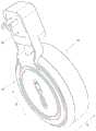
图1为本申请实施例提供的电子设备的立体示意图;FIG. 1 is a three-dimensional schematic diagram of an electronic device provided by an embodiment of the present application;
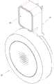
图2为本申请实施例提供的电子设备的另一角度立体示意图FIG. 2 is another perspective schematic diagram of the electronic device provided by the embodiment of the present application
图3为图1中电子设备的分解示意图;3 is an exploded schematic view of the electronic device in FIG. 1;
图4为图1中电子设备的剖视示意图;4 is a schematic cross-sectional view of the electronic device in FIG. 1;
图5为本申请实施例提供的固定支架的正面示意图;5 is a schematic front view of a fixing bracket provided by an embodiment of the present application;
图6为图5中固定支架的背面示意图;Fig. 6 is the back schematic diagram of the fixed bracket in Fig. 5;
图7为图1中电子设备的立体示意图。FIG. 7 is a schematic perspective view of the electronic device in FIG. 1 .
其中,图中各附图标记:Among them, each reference sign in the figure:
10、固定支架;20、主体部;30、适配器;40、数据线;11、第一安装部;12、第二安装部;13、连接部;14、第一磁性件;21、第二磁性件;22、第二安装槽;23、插槽;24、理线槽;25、通槽;41、第一端;42、中间段;43、第二端;111、插接限位结构;112、第一安装槽;113、卡钩;114、安装孔;115、第一贴合面;121、容纳腔;122、第一开口;123、第二开口;124、弹性卡扣;125、第二贴合面;126、侧面凹口;131、限位槽;132、弧形面;241、大径段;242、小径段;X、第一方向。10, fixing bracket; 20, main body; 30, adapter; 40, data cable; 11, first installation part; 12, second installation part; 13, connection part; 14, first magnetic part; 21, second
具体实施方式Detailed ways
为了使本申请所要解决的技术问题、技术方案及有益效果更加清楚明白,以下结合附图及实施例,对本申请进行进一步详细说明。应当理解,此处所描述的具体实施例仅仅用以解释本申请,并不用于限定本申请。In order to make the technical problems, technical solutions and beneficial effects to be solved by the present application clearer, the present application will be described in further detail below with reference to the accompanying drawings and embodiments. It should be understood that the specific embodiments described herein are only used to explain the present application, but not to limit the present application.
需要说明的是,当元件被称为“固定于”或“设置于”另一个元件,它可以直接在另一个元件上或者间接在该另一个元件上。当一个元件被称为是“连接于”另一个元件,它可以是直接连接到另一个元件或间接连接至该另一个元件上。It should be noted that when an element is referred to as being "fixed to" or "disposed on" another element, it can be directly on the other element or indirectly on the other element. When an element is referred to as being "connected to" another element, it can be directly connected to the other element or indirectly connected to the other element.
需要理解的是,术语“长度”、“宽度”、“上”、“下”、“前”、“后”、“左”、“右”、“竖直”、“水平”、“顶”、“底”、“内”、“外”等指示的方位或位置关系为基于附图所示的方位或位置关系,仅是为了便于描述本申请和简化描述,而不是指示或暗示所指的装置或元件必须具有特定的方位、以特定的方位构造和操作,因此不能理解为对本申请的限制。It is to be understood that the terms "length", "width", "upper", "lower", "front", "rear", "left", "right", "vertical", "horizontal", "top" , "bottom", "inside", "outside", etc. indicate the orientation or positional relationship based on the orientation or positional relationship shown in the accompanying drawings, only for the convenience of describing the application and simplifying the description, rather than indicating or implying the indicated A device or element must have a particular orientation, be constructed and operate in a particular orientation, and therefore should not be construed as a limitation of the present application.
此外,术语“第一”、“第二”仅用于描述目的,而不能理解为指示或暗示相对重要性或者隐含指明所指示的技术特征的数量。由此,限定有“第一”、“第二”的特征可以明示或者隐含地包括一个或者更多个该特征。在本申请的描述中,“多个”的含义是两个或两个以上,除非另有明确具体的限定。In addition, the terms "first" and "second" are only used for descriptive purposes, and should not be construed as indicating or implying relative importance or implying the number of indicated technical features. Thus, a feature defined as "first" or "second" may expressly or implicitly include one or more of that feature. In the description of the present application, "plurality" means two or more, unless otherwise expressly and specifically defined.
请一并参阅图1至图4,现对本申请实施例提供的固定支架10进行说明。Please refer to FIG. 1 to FIG. 4 together, and now the
该固定支架10用于电子设备的安装固定。具体的,该电子设备在本申请实施例中可以包括但不限于为网关设备等需要连接适配器的设备。The
电子设备包括主体部20及适配器30,固定支架10用于将电子设备的主体部20及适配器30进行安装固定,使得当适配器30插接于墙面后,整个电子设备能够挂设于墙面上。可以理解地,在本申请的其他实施例中,根据实际情况及具体需求,上述电子设备也可以是其他具有适配器30且结构尺寸不太大、重量不太重的电子设备,例如路由器、智能网关、智能音响、摄像头等。此外,该电子设备也可水平插接于地面或桌面上的插座上,固定支架10同样能够使得电子设备插接后整体小巧,占用面积不大,此处不做唯一限定。The electronic device includes a
请参阅图3,本实施例中所指电子设备是指具有适配器30的电子设备,因此该电子设备包括主体部20和适配器30,主体部20与适配器30通过数据线40连接。由于数据线40的存在,且数据线40为柔性结构,则使得主体部20与适配器30之间处于相对不固定状态。当适配器30插接于墙面的插座之后,主体部20通过数据线40悬挂,导致主体部20不稳定,或者将主体部20摆放于邻近的桌面上,这样就只能使用桌子附近的插座,占用空间大,使用不方便;而当将适配器30插接于水平插座上,适配器30与主体部20之间位置不固定,占据空间大,且外表零乱不美观、容易产生数据线/电源线接触不良的问题。Referring to FIG. 3 , the electronic device in this embodiment refers to an electronic device having an
而本申请的固定支架10能够解决上述问题,固定支架10能够实现主体部20与适配器30相对固定的目的。However, the fixing
具体的,请参阅图3及图4,固定支架10包括第一安装部11及第二安装部12,第一安装部11及第二安装部12固定连接,第一安装部11用于对电子设备的主体部20进行可拆卸地安装限位,第二安装部12用于对电子设备的适配器30进行可拆卸地安装限位。可以理解地,当将主体部20和适配器30分别安装于相互固定连接的第一安装部11及第二安装部12之后,主体部20与适配器30之间也处于相对固定状态,也即是通过该固定支架10的安装作用,将原本分散的主体部20与适配器30固定在一起,这样,当将适配器30插接于插座后,固定支架10跟随适配器30进行固定,则主体部20跟随适配器30固定,最终整个电子设备相对固定。Specifically, please refer to FIG. 3 and FIG. 4 , the fixing
本申请的固定支架10,通过第一安装部11及第二安装部12固定连接的设置,可以将电子设备的主体部20及适配器30相对固定,改善了适配器30与插座插接后出现接触不良的问题,同时也使得电子设备整体结构美观,拆装方便。且当适配器30插接插座后,电子设备结构小巧、美观。The fixing
请参阅图4,第一安装部11上设有第一磁性件14,第一磁性件14用于吸附于主体部20上以使第一安装部11贴设于主体部20的外壁。安装时,只需要将第一安装部11向主体部20的外壁靠近,当第一磁性件14吸附于主体部20后,第一安装部11将与主体部20的外壁紧紧贴合。第一安装部11通过第一磁性件14吸附贴合在主体部20的外壁,如此,使得第一安装部11的结构设计较为简单,第一安装部11的存在不会影响主体部20的外观,从而使得整个电子设备插接于墙面后,整体美观。此外,磁性安装,拆装方便,操作简单。Referring to FIG. 4 , the first mounting
请参阅图3,主体部20呈圆柱状,第一安装部11为贴设于主体部20轴向一端面上的薄板状结构,第一安装部11呈圆形,且第一安装部11的外径小于主体部20的外径,如此,使得第一安装部11占用体积小,且安装之后不会影响主体部20的整体外观。Please refer to FIG. 3 , the
在本实施例中,请参阅图4及图6,第一安装部11上设有插接限位结构111,插接限位结构111用于与主体部20形成插接配合,用于实现主体部20与第一安装部11之间的限位以及加强固定连接,本申请对与主体部30形成插接配合的插接限位结构111的设计数量及位置不做限定。安装时,可先通过插接限位结构111与主体部20对准定位,然后将第一安装部11与主体部20形成插接,最后通过第一磁性件14吸合,其定位准确,且连接牢靠。In this embodiment, please refer to FIG. 4 and FIG. 6 , the first mounting
具体的,请参阅图4,插接限位结构111为向主体部20延伸的凸部,凸部用于插入主体部20中以与主体部20形成插接配合。可以理解地,在本申请的其他实施例中,根据实际情况及具体要求,上述插接限位结构111也可以是凹槽,对应的,主体部20上设置凸部,此处不做唯一限定。Specifically, please refer to FIG. 4 , the
请参阅图4及图6,第一安装部11与第二安装部12沿第一方向X形成连接,第一方向X即为图4中的左右方向及图6中的上下方向,第一安装部11的侧面呈圆形,第二安装部12的侧面呈长形。当然,在本申请的其他实施例中,第一安装部11也可以是其他形状,只要与主体部20相适配即可,第二安装部12也可以是其他形状,只要与适配器30相适配即可,此处不做唯一限定。4 and 6 , the first mounting
插接限位结构111呈跑道型,且插接限位结构111的长度方向与第一方向X相同,如此,可增加主体部20与第一安装部11沿第一方向X上的连接强度。可以理解地,在本申请的其他实施例中,上述插接限位结构111也可以长圆形、椭圆形、长形、方形及多边形等,此处不做唯一限定。The
请参阅图1,插接限位结构111的插接方向设置为与适配器30的插接方向相同,具体的,插接限位结构111的插接方向即为图1中的Y方向,这样,当适配器30垂直插入墙面的插座之后,插接限位结构111处于水平状态,而主体部20的重力垂直向下,这样插接限位结构111能够在一定程度上承担对主体部20的承载作用,进而提高了该固定支架10对主体部20及适配器30的固定作用。Referring to FIG. 1 , the insertion direction of the
在本实施例中,第一磁性件14安装于插接限位结构111中,这样,插接的同时能够形成吸附连接,连接牢固,且结构设计简单。具体的,请参阅图4及图5,第一安装部11上开设有第一安装槽112,第一安装槽112自第一安装部11背离主体部20的一侧垂直向内延伸。实际设计时,只需将第一安装部11自背离主体部20的一侧向主体部20方向凹设即可,第一安装槽112及插接限位结构111同时形成,其结构简单,加工工艺简单,成本低。可以理解地,在本申请的其他实施例中,第一磁性件14与插接限位结构111也可以在第一安装部11上间隔设置,此处不做唯一限定。In this embodiment, the first
在本实施例中,请参阅图4,第一磁性件14通过卡扣方式安装于第一安装部11上。具体的,第一安装槽112中设有两卡钩113,两卡钩113沿第一方向X间隔设置,第一磁性件14即为磁块,磁块设于第一安装槽112中,并通过两卡钩113固定于第一安装槽112中。In this embodiment, please refer to FIG. 4 , the first
请参阅图4,两卡钩113均垂直于第一安装部11设置,两卡钩113的钩部相对设置,两卡钩113的背部均设有加强筋,加强筋呈棱柱状并用于加强两卡钩113的结构强度。Please refer to FIG. 4 , the two
可以理解地,在本申请的其他实施例中,第一磁性件14也可以通过粘贴方式或者螺钉锁紧方式安装于第一安装部11,粘贴方式即在第一磁性件14上涂设粘贴剂,然后将第一磁性件14粘贴于第一安装部11上;螺钉锁紧方式可以将第一磁性件14直接锁紧于第一安装部11上,或者通过安装板抵住第一磁性件14,然后将安装板锁紧于第一安装部11上。It can be understood that, in other embodiments of the present application, the first
请参阅图5,第一安装部11上还开设有备用的安装孔114,当通过适配器30将整个电子设备及固定支架10均挂在墙面上后,需要对整个结构与墙面的连接强度进行测试,如果测试发现连接强度不够,则可通过一个自攻螺钉穿过安装孔114并打入墙面上,从而加强了电子设备与墙面的连接强度。Please refer to FIG. 5 , the first mounting
安装孔114与插接限位结构111沿第一方向X间隔设置,安装孔114也呈腰形,且安装孔114的长度延伸方向与插接限位结构111的长度延伸方向相同。本申请对安装孔114的数量及位置不做限定。The installation holes 114 and the
请参阅图4及图6,安装孔114为沉孔,如此可将自攻螺钉的螺帽进行收容,不会影响第一安装部11与主体部20的贴合连接。加工时,将第一安装部11对应的位置从内侧向外侧凹设,然后开孔即可安装孔114,其加工工艺简单。Please refer to FIG. 4 and FIG. 6 , the mounting
在本实施例中,请参阅图4至图6,第二安装部12开设有容纳腔121,容纳腔121贯穿第二安装部12的相对两侧以形成第一开口122及第二开口123,第二开口123用于正对墙面设置,第一开口122用于背对墙面设置,第一开口122用于供适配器30装入容纳腔121,第二开口123用于供适配器30的插脚穿出。第一开口122的口径设置为大于适配器30的周向尺寸,第二开口123的口径设置为小于适配器30的周向尺寸且可以供适配器30的插脚穿过,安装时,适配器30从第一开口122装入容纳腔121中,且适配器30的插脚从第二开口123穿出并可插入墙面的插座上。In this embodiment, please refer to FIG. 4 to FIG. 6 , the second mounting
请参阅图4及图6,容纳腔121还贯穿第二安装部12靠近第一安装部11的一侧以侧面凹口126,侧面凹口126用于供适配器30的数据线40穿过。Please refer to FIGS. 4 and 6 , the
请参阅图4及图6,容纳腔121的侧壁上设有弹性卡扣124,弹性卡扣124用于弹性抵接适配器30的外壁,从而将适配器30卡紧于容纳腔121中,增加了适配器30在第二安装部12上的安装强度,且拆卸方便。Please refer to FIG. 4 and FIG. 6 , the side wall of the
弹性卡扣124凸设于侧壁上,弹性卡扣124沿容纳腔121的深度方向延伸,弹性卡扣124的厚度沿其长度方向由两端向中间逐渐增加,并形成有与适配器30相抵接的抵接点。The
请参阅图6,容纳腔121的四个侧壁上均设有两条弹性卡扣124,且两条弹性卡扣124均靠近每一侧壁的中间位置并间隔设置。可以理解地,在本申请的其他实施例中,弹性卡扣124的数量及位置布局还可以是其他情况,此处不做唯一限定。Referring to FIG. 6 , two
请参阅图4及图6,第一安装部11与第二安装部12之间连接有连接部13,连接部13上设有弧形面132及限位槽131,弧形面132靠近第一安装部11设置并用于与主体部20外周贴合,限位槽131连接于弧形面132与侧面凹口126之间的并用于限位数据线40,侧面凹口126连通于容纳腔121与限位槽131之间,数据线40的一端容置于限位槽131中并穿过侧面凹口126与适配器30连接。Please refer to FIG. 4 and FIG. 6 , a connecting
在本实施例中,请参阅图5及图6,第一安装部11、连接部13及第二安装部12一体连接,这样使得第一安装部11与第二安装部12的连接强度更高,也即是该固定支架10对主体部20及适配器30的安装固定效果更好,通过固定支架10即可将主体部20跟随适配器30一起挂设在墙面上。此外,通过一体连接的设置,使得整个固定支架10的加工工艺更加简单,成本低。可以理解地,在本申请的其他实施例中,上述第一安装部11与第二安装部12也可以分体设计,即将第一安装部11与第二安装部12通过紧固件锁紧,此处不做唯一限定。In this embodiment, please refer to FIG. 5 and FIG. 6 , the first mounting
请参阅图4,沿插接限位结构111的插接方向Y上,第二安装部12的厚度大于第一安装部11的厚度。Referring to FIG. 4 , along the insertion direction Y of the
第一安装部11具有用于与墙面贴合的第一贴合面115,第一贴合面115即为第一安装部11背离主体部20的一侧面,第二安装部12具有用于与插座贴合的第二贴合面125,第二贴合面125即为第二安装部12对应第二开口123的一侧面。第一贴合面115与第二贴合面125沿插接限位结构111的插接方向Y上具有第一距离,插座表面凸出于墙面有第二距离,第一距离设置为与第二距离相适配。The first mounting
本申请还提供了一种电子设备,包括主体部20及适配器30,电子设备可拆卸地安装于上述的固定支架10。主体部20可拆卸地安装限位于固定支架10的第一安装部11,适配器30可拆卸地限位于固定支架10的第二安装部12。主体20上设有插槽23,插槽23与插接限位结构111形成插接配合。本申请实施例提供电子设备使用上述固定支架10后,使得电子设备安装之后,主体部20与适配器30位置相对固定,改善了适配器30与插座插接后出现接触不良的问题,同时也使得电子设备整体结构美观,且拆装方便。The present application also provides an electronic device including a
主体部20上设有第二磁性件21,第一磁性件14与第二磁性件21相互吸引以使主体部20与第一安装部11贴合,适配器30安装于第二安装部12。通过第一磁性件14及第二磁性件21的设置,使得适配器30插接于插座后,主体部20能跟随适配器30挂设于墙面上,且挂接牢靠。同时也使得整个电子设备安装之后表面美观。The
请参阅图4,主体部20包括壳体,壳体内侧设有第二安装槽22,第二磁性件21同样为磁块,第二磁性件21容置于第二安装槽22中。且第二安装槽22中同样设有卡钩结构,通过卡钩结构将第二磁性件21卡接于第二安装槽22中。Referring to FIG. 4 , the
请参阅图4,插槽23由壳体自外向内凹设形成,插槽23与第二安装槽22背对背设置,且插槽23同样呈跑道型。安装时,插接限位结构111插入插槽23中以形成插接配合。Referring to FIG. 4 , the
在本实施例中,请参阅图3及图7,适配器30与主体部20之间连接有数据线40,主体部20一侧外壁上开设有理线槽24,数据线40收纳于理线槽24中。具体是,主体部20与第一安装部11贴合的一侧外壁设有理线槽24,通过将理线槽24设置于主体部20上,且设于主体部20与第一安装部11贴合的一侧外壁上,这样无需在第二安装部12上额外设置收纳结构,减少固定支架10的结构复杂性,同时还能够通过第一安装部11将数据线40进行遮盖,使得数据线40不外露,从而使得整体结构外表美观。在本申请的其他实施例中,理线槽24也可以设于主体部20的其他侧用于收纳数据线40,此处不做唯一限定。In this embodiment, please refer to FIG. 3 and FIG. 7 , a
在本实施例中,请参阅图7,数据线40包括依次连接的第一端41、中间段42及第二端43,第一端41用于与主体部20的电源模块形成插接,第二端43与适配器30连接。理线槽24包括大径段241及小径段242,大径段241靠近主体部20的电源模块设置,大径段241呈方形,且大径段241的尺寸大于第一端41的尺寸,小径段242自大径段241弯曲延伸至主体部20的外边缘,小径段242的内径与中间段42的外径相适配。第一端41容置于大径段241,中间段42从第一端41到第二端43依次卡入小径段242中,第二端43伸出小径段242以与适配器30连接。由此可见,本申请的数据线40的尺寸固定,数据线40在安装时无需进行缠绕理线,只需要将中间段42卡入小径段242即可,操作简单。可选地,如果中间段42的数据线40较长,还可以将部分收纳至大径段241。In this embodiment, please refer to FIG. 7 , the
请参阅图7,主体部20开设有通槽25,通槽25自大径段241延伸至主体部20内侧,以实现适配器30与电子设备的电连接。Referring to FIG. 7 , the
以上所述仅为本申请的较佳实施例而已,并不用以限制本申请,凡在本申请的精神和原则之内所作的任何修改、等同替换和改进等,均应包含在本申请的保护范围之内。The above descriptions are only preferred embodiments of the present application and are not intended to limit the present application. Any modifications, equivalent replacements and improvements made within the spirit and principles of the present application shall be included in the protection of the present application. within the range.
Claims (12)
Translated fromChinesePriority Applications (2)
| Application Number | Priority Date | Filing Date | Title |
|---|---|---|---|
| CN202010321141.9ACN111464885A (en) | 2020-04-22 | 2020-04-22 | Fixing support and electronic equipment applying same |
| US17/190,163US11682858B2 (en) | 2020-04-22 | 2021-03-02 | Mounting bracket and electronic device |
Applications Claiming Priority (1)
| Application Number | Priority Date | Filing Date | Title |
|---|---|---|---|
| CN202010321141.9ACN111464885A (en) | 2020-04-22 | 2020-04-22 | Fixing support and electronic equipment applying same |
Publications (1)
| Publication Number | Publication Date |
|---|---|
| CN111464885Atrue CN111464885A (en) | 2020-07-28 |
Family
ID=71680254
Family Applications (1)
| Application Number | Title | Priority Date | Filing Date |
|---|---|---|---|
| CN202010321141.9AWithdrawnCN111464885A (en) | 2020-04-22 | 2020-04-22 | Fixing support and electronic equipment applying same |
Country Status (2)
| Country | Link |
|---|---|
| US (1) | US11682858B2 (en) |
| CN (1) | CN111464885A (en) |
Cited By (1)
| Publication number | Priority date | Publication date | Assignee | Title |
|---|---|---|---|---|
| CN111970868A (en)* | 2020-08-19 | 2020-11-20 | 中磊电子(苏州)有限公司 | Network communication device set and transformer |
Citations (7)
| Publication number | Priority date | Publication date | Assignee | Title |
|---|---|---|---|---|
| US20110187323A1 (en)* | 2010-02-03 | 2011-08-04 | James Robert Gourley | Mobile Electronic Device AC Charger Mount |
| CN205716304U (en)* | 2016-06-23 | 2016-11-23 | 成都市极米科技有限公司 | A kind of floor stand and projector equipment |
| CN206458988U (en)* | 2016-12-29 | 2017-09-01 | 科立讯通信股份有限公司 | Mounting bracket |
| CN107289250A (en)* | 2017-07-21 | 2017-10-24 | 肖成英 | Flat electronic equipment mounting bracket |
| CN207339819U (en)* | 2017-10-13 | 2018-05-08 | 中山悦驰通信科技有限公司 | A kind of dust-proof wireless signal transmitter easy to fixation |
| US20190281713A1 (en)* | 2018-03-07 | 2019-09-12 | Jennifer Lovette-Cephus | Storage apparatus and methods of storing and using electronic devices during charging |
| CN211909038U (en)* | 2020-04-22 | 2020-11-10 | 深圳市晨北科技有限公司 | Fixed bracket and electronic equipment using the same |
Family Cites Families (18)
| Publication number | Priority date | Publication date | Assignee | Title |
|---|---|---|---|---|
| US5648712A (en)* | 1995-08-29 | 1997-07-15 | Asian Micro Sources, Inc. | Universally interchangeable and modular power supply with integrated battery charger |
| US5656914A (en)* | 1995-10-31 | 1997-08-12 | Motorola, Inc. | Battery charger having pocket with multiple sets of charging contacts |
| US6316911B1 (en)* | 1997-08-08 | 2001-11-13 | Black & Decker Inc. | Battery and flashlight recharger |
| US6049192A (en)* | 1999-03-18 | 2000-04-11 | Motorola, Inc. | Battery charger having moving door housing for a battery |
| US6553711B1 (en)* | 2000-03-22 | 2003-04-29 | Long Well Electronics Corp. | Switchable mosquito expelling/killing device |
| TW519330U (en)* | 2001-09-04 | 2003-01-21 | Delta Electronics Inc | Rotating plug |
| US6498458B1 (en)* | 2001-11-01 | 2002-12-24 | Cliff Chen | Battery charger for charging a wireless signal source and detachable receiver |
| TW543994U (en)* | 2001-12-25 | 2003-07-21 | Sheng-Shing Liau | Easy carrying multi-function charger |
| GB0308141D0 (en)* | 2003-03-24 | 2003-05-14 | Research In Motion Ltd | Battery charger adapter |
| US7176656B2 (en)* | 2004-06-22 | 2007-02-13 | Campbell Hausfeld/Scott Fetzer Company | Tool with battery pack |
| US7365514B2 (en)* | 2004-10-26 | 2008-04-29 | Totex Design Limited | Battery charger |
| US7658625B2 (en)* | 2008-03-07 | 2010-02-09 | Microsoft Corporation | AC Power adapter with swiveling plug having folding prongs |
| CA2717860C (en)* | 2008-03-07 | 2016-11-08 | Milwaukee Electric Tool Corporation | Battery pack for use with a power tool and a non-motorized sensing tool |
| US7812567B2 (en)* | 2008-06-12 | 2010-10-12 | Wen Hong Shen | Battery charger stand set for motor vehicle |
| US8072183B2 (en)* | 2009-03-12 | 2011-12-06 | Griffin Technology, Inc. | Multiple interface device charger with removable battery pack |
| US8686683B2 (en)* | 2010-03-22 | 2014-04-01 | Audiovox Corporation | Charge clip |
| US8564243B2 (en)* | 2011-03-01 | 2013-10-22 | Tennrich International Corp. | Charging module |
| US9437983B2 (en)* | 2015-01-26 | 2016-09-06 | Progressive Industries, Inc. | Electrical connection box |
- 2020
- 2020-04-22CNCN202010321141.9Apatent/CN111464885A/ennot_activeWithdrawn
- 2021
- 2021-03-02USUS17/190,163patent/US11682858B2/enactiveActive
Patent Citations (7)
| Publication number | Priority date | Publication date | Assignee | Title |
|---|---|---|---|---|
| US20110187323A1 (en)* | 2010-02-03 | 2011-08-04 | James Robert Gourley | Mobile Electronic Device AC Charger Mount |
| CN205716304U (en)* | 2016-06-23 | 2016-11-23 | 成都市极米科技有限公司 | A kind of floor stand and projector equipment |
| CN206458988U (en)* | 2016-12-29 | 2017-09-01 | 科立讯通信股份有限公司 | Mounting bracket |
| CN107289250A (en)* | 2017-07-21 | 2017-10-24 | 肖成英 | Flat electronic equipment mounting bracket |
| CN207339819U (en)* | 2017-10-13 | 2018-05-08 | 中山悦驰通信科技有限公司 | A kind of dust-proof wireless signal transmitter easy to fixation |
| US20190281713A1 (en)* | 2018-03-07 | 2019-09-12 | Jennifer Lovette-Cephus | Storage apparatus and methods of storing and using electronic devices during charging |
| CN211909038U (en)* | 2020-04-22 | 2020-11-10 | 深圳市晨北科技有限公司 | Fixed bracket and electronic equipment using the same |
Cited By (1)
| Publication number | Priority date | Publication date | Assignee | Title |
|---|---|---|---|---|
| CN111970868A (en)* | 2020-08-19 | 2020-11-20 | 中磊电子(苏州)有限公司 | Network communication device set and transformer |
Also Published As
| Publication number | Publication date |
|---|---|
| US20210336383A1 (en) | 2021-10-28 |
| US11682858B2 (en) | 2023-06-20 |
Similar Documents
| Publication | Publication Date | Title |
|---|---|---|
| CN107086507B (en) | Wire fixing clamp and air conditioner | |
| CN209856718U (en) | Communication equipment installation device and assembling and fixing support thereof | |
| CN211909038U (en) | Fixed bracket and electronic equipment using the same | |
| WO2016180002A1 (en) | Device mounting apparatus | |
| CN111464885A (en) | Fixing support and electronic equipment applying same | |
| JPH11233960A (en) | Assembled housing for electrical equipment | |
| CN209819353U (en) | Ceiling lamp | |
| CN206895053U (en) | Back plate, rear shell and rear shell mounting structure | |
| CN209963378U (en) | Wire pressing plate and electric appliance with same | |
| CN209948182U (en) | Tower bridge power supply box and tower bridge | |
| US12238889B1 (en) | Cable management assembly and cable management method | |
| CN218954776U (en) | Clamping hanging type installation assembly, double-clamping buckle installation assembly and lamp | |
| CN207233978U (en) | Fixing support and fixing structure | |
| CN211144876U (en) | A quick-release fan module | |
| CN205985670U (en) | Adapter | |
| WO2020113541A1 (en) | Adapter | |
| TW201344397A (en) | Connection port device and server using same | |
| CN220038019U (en) | Mounting brackets and terminal mounting structures | |
| CN215773401U (en) | Connecting interface anti-drop mechanism for network switching equipment | |
| CN218770459U (en) | Socket panel, socket assembly and energy storage power supply | |
| TWI846574B (en) | Cable management component and cable management method | |
| CN208174183U (en) | Medical multifunctional support arm wire slot quick release buckle structure | |
| JP3406906B1 (en) | Mounting method, mounting device and mounting system for network concentrator | |
| CN219712828U (en) | Suspension device and display equipment using it | |
| CN212115967U (en) | A sheet piece mounting bracket and sheet piece assembly |
Legal Events
| Date | Code | Title | Description |
|---|---|---|---|
| PB01 | Publication | ||
| PB01 | Publication | ||
| SE01 | Entry into force of request for substantive examination | ||
| SE01 | Entry into force of request for substantive examination | ||
| WW01 | Invention patent application withdrawn after publication | ||
| WW01 | Invention patent application withdrawn after publication | Application publication date:20200728 |