CN111464020A - Heat radiator for direct current converter - Google Patents
Heat radiator for direct current converterDownload PDFInfo
- Publication number
- CN111464020A CN111464020ACN202010438767.8ACN202010438767ACN111464020ACN 111464020 ACN111464020 ACN 111464020ACN 202010438767 ACN202010438767 ACN 202010438767ACN 111464020 ACN111464020 ACN 111464020A
- Authority
- CN
- China
- Prior art keywords
- pipe
- converter
- heat exchange
- heat dissipation
- shaped
- Prior art date
- Legal status (The legal status is an assumption and is not a legal conclusion. Google has not performed a legal analysis and makes no representation as to the accuracy of the status listed.)
- Pending
Links
- 230000017525heat dissipationEffects0.000claimsabstractdescription23
- 239000002826coolantSubstances0.000claimsabstractdescription9
- 239000003507refrigerantSubstances0.000claimsdescription5
- 238000001816coolingMethods0.000abstractdescription22
- 238000010586diagramMethods0.000description4
- 239000000463materialSubstances0.000description3
- 238000000034methodMethods0.000description3
- 230000009286beneficial effectEffects0.000description2
- 238000004140cleaningMethods0.000description2
- 230000000694effectsEffects0.000description2
- 238000009434installationMethods0.000description2
- XLYOFNOQVPJJNP-UHFFFAOYSA-NwaterSubstancesOXLYOFNOQVPJJNP-UHFFFAOYSA-N0.000description2
- 239000000428dustSubstances0.000description1
- 239000011810insulating materialSubstances0.000description1
- 230000007774longtermEffects0.000description1
- 239000007769metal materialSubstances0.000description1
- 238000012986modificationMethods0.000description1
- 230000004048modificationEffects0.000description1
Images


Classifications
- H—ELECTRICITY
- H02—GENERATION; CONVERSION OR DISTRIBUTION OF ELECTRIC POWER
- H02M—APPARATUS FOR CONVERSION BETWEEN AC AND AC, BETWEEN AC AND DC, OR BETWEEN DC AND DC, AND FOR USE WITH MAINS OR SIMILAR POWER SUPPLY SYSTEMS; CONVERSION OF DC OR AC INPUT POWER INTO SURGE OUTPUT POWER; CONTROL OR REGULATION THEREOF
- H02M3/00—Conversion of DC power input into DC power output
- H—ELECTRICITY
- H05—ELECTRIC TECHNIQUES NOT OTHERWISE PROVIDED FOR
- H05K—PRINTED CIRCUITS; CASINGS OR CONSTRUCTIONAL DETAILS OF ELECTRIC APPARATUS; MANUFACTURE OF ASSEMBLAGES OF ELECTRICAL COMPONENTS
- H05K5/00—Casings, cabinets or drawers for electric apparatus
- H05K5/02—Details
- H05K5/0213—Venting apertures; Constructional details thereof
- H—ELECTRICITY
- H05—ELECTRIC TECHNIQUES NOT OTHERWISE PROVIDED FOR
- H05K—PRINTED CIRCUITS; CASINGS OR CONSTRUCTIONAL DETAILS OF ELECTRIC APPARATUS; MANUFACTURE OF ASSEMBLAGES OF ELECTRICAL COMPONENTS
- H05K5/00—Casings, cabinets or drawers for electric apparatus
- H05K5/02—Details
- H05K5/0217—Mechanical details of casings
- H—ELECTRICITY
- H05—ELECTRIC TECHNIQUES NOT OTHERWISE PROVIDED FOR
- H05K—PRINTED CIRCUITS; CASINGS OR CONSTRUCTIONAL DETAILS OF ELECTRIC APPARATUS; MANUFACTURE OF ASSEMBLAGES OF ELECTRICAL COMPONENTS
- H05K7/00—Constructional details common to different types of electric apparatus
- H05K7/20—Modifications to facilitate cooling, ventilating, or heating
- H05K7/2089—Modifications to facilitate cooling, ventilating, or heating for power electronics, e.g. for inverters for controlling motor
Landscapes
- Engineering & Computer Science (AREA)
- Microelectronics & Electronic Packaging (AREA)
- Power Engineering (AREA)
- Physics & Mathematics (AREA)
- Thermal Sciences (AREA)
- Dc-Dc Converters (AREA)
- Cooling Or The Like Of Electrical Apparatus (AREA)
- Cooling Or The Like Of Semiconductors Or Solid State Devices (AREA)
Abstract
Translated fromChinese
Description
Translated fromChinese技术领域technical field
本发明属于电力设备技术领域,尤其涉及一种直流变换器的散热装置。The invention belongs to the technical field of electric power equipment, and in particular relates to a heat dissipation device of a DC converter.
背景技术Background technique
直流变换器在工作时会产生大量的热量,如果散热不及时就会使直流变换器的温度过高,影响其正常工作。The DC converter will generate a lot of heat when it is working. If the heat dissipation is not timely, the temperature of the DC converter will be too high, which will affect its normal operation.
目前直流变换器运用得比较普遍的依然通过风扇送风等以空气为冷却介质的供冷方式,但在实际运行中还会存在送风不均匀、供冷效率低的问题,严重影响了设备的冷却效果,并且以送风的方式冷却会将空气中的灰尘吹送到直流变换器的内部结构中,影响了直流变换器的性能。At present, DC converters are still widely used in the cooling mode that uses air as the cooling medium, such as air supply by fans. However, in actual operation, there are still problems of uneven air supply and low cooling efficiency, which seriously affects the equipment performance. The cooling effect, and cooling by means of air supply will blow the dust in the air into the internal structure of the DC converter, which affects the performance of the DC converter.
现有的直流变换器水冷方式冷却,水管拆卸麻烦,现有大多数的水冷散热方式的水管和和直流变换器是一体的,水管在长时间使用后,无法拆卸清洗。The existing DC converter is cooled by water-cooling, and the water pipe is troublesome to disassemble. Most of the existing water-cooled heat dissipation method is integrated with the DC converter, and the water pipe cannot be disassembled and cleaned after long-term use.
因此我们提出一种直流变换器的散热装置,以便解决上述中所提出的问题。Therefore, we propose a cooling device for a DC converter in order to solve the above-mentioned problems.
发明内容SUMMARY OF THE INVENTION
(一)要解决的技术问题(1) Technical problems to be solved
为了解决现有技术的上述问题,本发明提供一种直流变换器的散热装置,解决了现有技术中存在的直流变换器的散热装置供冷效率低、无法拆卸清洗的问题。In order to solve the above problems of the prior art, the present invention provides a heat sink for a DC converter, which solves the problems of low cooling efficiency and inability to disassemble and clean the heat sink of the DC converter in the prior art.
(二)技术方案(2) Technical solutions
为了达到上述目的,本发明采用的主要技术方案包括:In order to achieve the above-mentioned purpose, the main technical scheme adopted in the present invention includes:
本发明提供了一种直流变换器的散热装置,包括直流变换器本体和壳体,The invention provides a heat dissipation device of a DC converter, comprising a DC converter body and a casing,
还包括热交换组件,所述热交换组件用于直流变换器的散热;Also includes a heat exchange component, the heat exchange component is used for heat dissipation of the DC converter;
所述壳体设有一开口侧;the housing is provided with an open side;
所述直流变换器本体设置在所述壳体内部,所述直流变换器的一端面与所述开口侧对应连接;The DC converter body is arranged inside the casing, and one end face of the DC converter is correspondingly connected to the opening side;
所述热交换组件可拆卸的设置在所述壳体的内侧壁,所述热交换组件内部设有流动的冷却介质。The heat exchange assembly is detachably arranged on the inner side wall of the casing, and a cooling medium is arranged inside the heat exchange assembly.
根据本发明,所述热交换组件包括输入管、输出管和多个U型管组;According to the present invention, the heat exchange assembly includes an input pipe, an output pipe and a plurality of U-shaped pipe groups;
多个所述U型管组等间距水平放置;A plurality of the U-shaped tube groups are placed horizontally at equal intervals;
所述U型管组的一端口与所述输入管转动连接,所述U型管组的另一端口与所述输出管转动连接。One port of the U-shaped pipe group is rotatably connected with the input pipe, and the other port of the U-shaped pipe group is rotatably connected with the output pipe.
根据本发明,所述U型管组包括U型管、第一旋转管和第二旋转管;According to the present invention, the U-shaped pipe group includes a U-shaped pipe, a first rotating pipe and a second rotating pipe;
所述U型管上设有进口端和出口端;The U-shaped pipe is provided with an inlet end and an outlet end;
所述第一旋转管的一端与所述U型管的进口端转动连接,所述第一旋转管的另一端与所述输入管转动连接;One end of the first rotating pipe is rotatably connected with the inlet end of the U-shaped pipe, and the other end of the first rotating pipe is rotatably connected with the input pipe;
所述第二旋转管的一端与所述U型管的出口端转动连接,所述第二旋转管的另一端与所述输出管转动连接。One end of the second rotating pipe is rotatably connected with the outlet end of the U-shaped pipe, and the other end of the second rotating pipe is rotatably connected with the output pipe.
根据本发明,所述第一旋转管的近顶端和近底端分别设置有方向相反的螺纹,所述第一旋转管的第一端与输入管螺纹连接,所述第一旋转管的第二端与U型管的进口端螺纹连接;According to the present invention, the proximal top end and the proximal bottom end of the first rotating pipe are respectively provided with threads in opposite directions, the first end of the first rotating pipe is threadedly connected with the input pipe, and the second rotating pipe The end is threadedly connected with the inlet end of the U-shaped pipe;
所述第二旋转管的近顶端和近底端分别设置有方向相反的螺纹,所述第二旋转管的第一端与输出管螺纹连接,所述第二旋转管的第二端与U型管的出口端螺纹连接。The proximal top end and the proximal bottom end of the second rotating pipe are respectively provided with threads in opposite directions, the first end of the second rotating pipe is threadedly connected with the output pipe, and the second end of the second rotating pipe is connected to the U-shaped The outlet end of the tube is threaded.
根据本发明,所述壳体内侧开设有多个与所述热交换组件相匹配的凹槽,所述热交换组件放置在所述凹槽内。According to the present invention, a plurality of grooves matching with the heat exchanging components are formed on the inner side of the casing, and the heat exchanging components are placed in the grooves.
根据本发明,所述壳体的顶部开设有多个散热孔。According to the present invention, the top of the casing is provided with a plurality of heat dissipation holes.
根据本发明,所述输入管的进口端设有单向阀。According to the present invention, the inlet end of the input pipe is provided with a one-way valve.
根据本发明,所述冷却介质为制冷剂。According to the present invention, the cooling medium is a refrigerant.
(三)有益效果(3) Beneficial effects
本发明的有益效果是:The beneficial effects of the present invention are:
本发明提供的一种直流变换器的散热装置,将热交换组件设置在壳体内部,利用壳体的导热性能对直流变换器和热交换组件之间进行热交换,使得制冷量全部在壳体内部用于冷却直流变换器,减少了冷量损失,提高了冷却效率和冷却能力,并且热交换组件与壳体可拆卸连接,便于热交换组件的清洗。The present invention provides a heat dissipation device for a DC converter. The heat exchange component is arranged inside the casing, and the heat conduction performance of the casing is used to exchange heat between the DC converter and the heat exchange component, so that all the cooling capacity is stored in the casing. The inside is used to cool the DC converter, which reduces the loss of cooling capacity, improves the cooling efficiency and cooling capacity, and the heat exchange component is detachably connected to the shell, which is convenient for cleaning of the heat exchange component.
附图说明Description of drawings
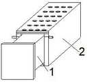
图1为本发明直流变换器的散热装置的结构示意图;Fig. 1 is the structural schematic diagram of the heat sink of the DC converter of the present invention;
图2为本发明壳体和热交换组件的结构示意图;Fig. 2 is the structural schematic diagram of the casing and the heat exchange assembly of the present invention;
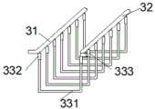
图3为本发明热交换组件的结构示意图;3 is a schematic structural diagram of a heat exchange assembly of the present invention;
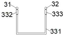
图4为本发明热交换组件的正视图;4 is a front view of the heat exchange assembly of the present invention;
图5为本发明第一旋转管的结构示意图。FIG. 5 is a schematic structural diagram of the first rotating tube of the present invention.
【附图标记说明】[Description of reference numerals]
1:直流变换器本体;2:壳体;21:凹槽;22:散热孔;31:输入管;32:输出管;331:U型管;332:第一旋转管;333:第二旋转管。1: DC converter body; 2: shell; 21: groove; 22: cooling hole; 31: input pipe; 32: output pipe; 331: U-shaped pipe; 332: first rotating pipe; 333: second rotating pipe Tube.
具体实施方式Detailed ways
为了更好的解释本发明,以便于理解,下面结合附图,通过具体实施方式,对本发明作详细描述。In order to better explain the present invention and facilitate understanding, the present invention will be described in detail below with reference to the accompanying drawings and through specific embodiments.
本发明提供了一种直流变换器的散热装置,包括直流变换器本体1和壳体2,还包括热交换组件,所述热交换组件用于直流变换器的散热,所述壳体2设有一开口侧,所述直流变换器本体1设置在所述壳体2内部,所述直流变换器的一端面与所述开口侧对应连接,所述热交换组件可拆卸的设置在所述壳体2的内侧壁,所述热交换组件内部设有流动的冷却介质。The present invention provides a heat dissipation device for a DC converter, which includes a
在本实施例中将热交换组件设置在壳体2内部,利用壳体2的导热性能对直流变换器和热交换组件之间进行热交换,使得制冷量全部在壳体2内部用于冷却直流变换器,减少了冷量损失,提高了冷却效率和冷却能力。其中,热交换组件在壳体2的内部可拆卸连接,便于热交换组件与壳体2的安装,当热交换组件长时间使用内部出现污垢,影响制冷效果时,可将热交换组件从壳体2内部拆卸清洗,进一步提高了冷却装置的冷却效率和冷却性能。In this embodiment, the heat exchange assembly is arranged inside the
当然,热交换组件和壳体2的材料可以为导热性良好的金属材料。为了保证安全,还可以在壳体2的内部的表面涂覆绝缘材料。Of course, the materials of the heat exchange component and the
具体地,所述热交换组件包括输入管31、输出管32和多个U型管组,多个所述U型管组等间距水平放置,所述U型管组的一端口与所述输入管31转动连接,所述U型管组的另一端口与所述输出管32转动连接。其中输入管31的进口端和输出管32的出口端分别穿过壳体2的两侧壁与外界连接。Specifically, the heat exchange assembly includes an
优选地,所述U型管组包括U型管331、第一旋转管332和第二旋转管333,所述U型管331上设有进口端和出口端,所述第一旋转管332的一端与所述U型管331的进口端转动连接,所述第一旋转管332的另一端与所述输入管31转动连接。所述第二旋转管333的一端与所述U型管331的出口端转动连接,所述第二旋转管333的另一端与所述输出管32转动连接,其中第一旋转管332和第二旋转管333中间为中空结构。Preferably, the U-shaped pipe group includes a
具体地,所述第一旋转管332的近顶端和近底端分别设置有方向相反的螺纹,所述第一旋转管332的第一端与输入管31螺纹连接,所述第一旋转管332的第二端与U型管331的进口端螺纹连接,所述第二旋转管333的近顶端和近底端分别设置有方向相反的螺纹,所述第二旋转管333的第一端与输出管32螺纹连接,所述第二旋转管333的第二端与U型管331的出口端螺纹连接。Specifically, the proximal top and proximal bottom ends of the first rotating
在实际应用中,输入管31、输出管32与U型管组的连接处设有螺纹连接孔,当输入管31、输出管32与U型管组配合连接时,分别转动调节第一旋转管332和第二旋转管333进行调节,因为旋转管的近上端和近底端分别带有正螺纹和反螺纹,当顺时针转动旋转管时旋转管上升分别于输入管31、输出管32螺纹连接,当逆时针转动旋转管时,使旋转管下降分别与输入管31、输出管32拆卸,操作简便,可以直接用手操作,无需使用工具。In practical application, threaded connection holes are provided at the connection between the
进一步地,所述壳体2内侧开设有多个与所述热交换组件相匹配的凹槽21,所述热交换组件放置在所述凹槽21内。在实际应用中,输入管31、输出管32与U型管组可选用圆柱管体,当然也可以选为柱体,只要当输入管31和输出管32放置在凹槽21内时,圆柱和柱体不突出凹槽21即可,不影响直流变换器本体1的安装。Further, a plurality of
在本实施例中,所述壳体2的顶部开设有多个散热孔22,可进一步提高直流变换器的散热能力。其中,所述输入管31的进口端可设有单向阀,可以用于防止冷却介质的回流。In this embodiment, the top of the
具体地,所述冷却介质为制冷剂。制冷剂选择不会与壳体2的材料和直流变换器本体1的材料发生反应的制冷剂,即使发生泄漏也不会对直流变换器本体1造成大的影响。Specifically, the cooling medium is a refrigerant. A refrigerant that does not react with the material of the
本发明实施例中的直流变换器的散热装置的原理为:The principle of the cooling device of the DC converter in the embodiment of the present invention is:
制冷剂从输入管31的进口端流入后,依次进入第一旋转管332、U型管331、第二旋转管333,最后从输出管32的出口端流出。并在流动过程中经经易导热的壳体2与直流变换器进行热交换,在应用过程中,直流变换器本体1直接与壳体2的底端、左端、右端直接接触,进行直接接触的热交换。After the refrigerant flows in from the inlet end of the
以上对本发明的具体实施例进行的描述只是为了说明本发明的技术路线和特点,其目的在于让本领域内的技术人员能够了解本发明的内容并据以实施,但本发明并不限于上述特定实施方式。凡是在本发明权利要求的范围内做出的各种变化或修饰,都应涵盖在本发明的保护范围内。The above description of the specific embodiments of the present invention is only to illustrate the technical route and characteristics of the present invention, and its purpose is to enable those skilled in the art to understand the content of the present invention and implement it accordingly, but the present invention is not limited to the above-mentioned specific embodiments. implementation. Any changes or modifications made within the scope of the claims of the present invention should be covered within the protection scope of the present invention.
Claims (8)
Translated fromChinesePriority Applications (1)
| Application Number | Priority Date | Filing Date | Title |
|---|---|---|---|
| CN202010438767.8ACN111464020A (en) | 2020-05-22 | 2020-05-22 | Heat radiator for direct current converter |
Applications Claiming Priority (1)
| Application Number | Priority Date | Filing Date | Title |
|---|---|---|---|
| CN202010438767.8ACN111464020A (en) | 2020-05-22 | 2020-05-22 | Heat radiator for direct current converter |
Publications (1)
| Publication Number | Publication Date |
|---|---|
| CN111464020Atrue CN111464020A (en) | 2020-07-28 |
Family
ID=71680058
Family Applications (1)
| Application Number | Title | Priority Date | Filing Date |
|---|---|---|---|
| CN202010438767.8APendingCN111464020A (en) | 2020-05-22 | 2020-05-22 | Heat radiator for direct current converter |
Country Status (1)
| Country | Link |
|---|---|
| CN (1) | CN111464020A (en) |
Cited By (1)
| Publication number | Priority date | Publication date | Assignee | Title |
|---|---|---|---|---|
| CN113489311A (en)* | 2021-08-19 | 2021-10-08 | 江苏博乐电力能源装备有限公司 | DC-DC switching power supply |
Citations (8)
| Publication number | Priority date | Publication date | Assignee | Title |
|---|---|---|---|---|
| US20020117291A1 (en)* | 2000-05-25 | 2002-08-29 | Kioan Cheon | Computer having cooling apparatus and heat exchanging device of the cooling apparatus |
| US20120127655A1 (en)* | 2010-11-23 | 2012-05-24 | Inventec Corporation | Server cabinet |
| CN108278909A (en)* | 2018-01-17 | 2018-07-13 | 嘉善超盛五金材料有限公司 | A kind of cooling water heat dissipating device and its circulation cooling method of electric furnace mold |
| CN207711782U (en)* | 2017-07-17 | 2018-08-10 | 上海汽车集团股份有限公司 | Integral type power control unit |
| WO2019050122A1 (en)* | 2017-09-06 | 2019-03-14 | 이현환 | Heat-radiating device casing having refrigerant pipe embedded therein and apparatus and method for manufacturing same |
| CN109890183A (en)* | 2019-04-10 | 2019-06-14 | 东北大学 | A data center cooling cabinet |
| CN109889024A (en)* | 2019-01-28 | 2019-06-14 | 四川富肯斯科技有限公司 | A high-power DC converter cooling system |
| CN110581657A (en)* | 2019-09-23 | 2019-12-17 | 中国科学院电工研究所 | A Photovoltaic High Voltage DC Series Grid-connected System |
- 2020
- 2020-05-22CNCN202010438767.8Apatent/CN111464020A/enactivePending
Patent Citations (8)
| Publication number | Priority date | Publication date | Assignee | Title |
|---|---|---|---|---|
| US20020117291A1 (en)* | 2000-05-25 | 2002-08-29 | Kioan Cheon | Computer having cooling apparatus and heat exchanging device of the cooling apparatus |
| US20120127655A1 (en)* | 2010-11-23 | 2012-05-24 | Inventec Corporation | Server cabinet |
| CN207711782U (en)* | 2017-07-17 | 2018-08-10 | 上海汽车集团股份有限公司 | Integral type power control unit |
| WO2019050122A1 (en)* | 2017-09-06 | 2019-03-14 | 이현환 | Heat-radiating device casing having refrigerant pipe embedded therein and apparatus and method for manufacturing same |
| CN108278909A (en)* | 2018-01-17 | 2018-07-13 | 嘉善超盛五金材料有限公司 | A kind of cooling water heat dissipating device and its circulation cooling method of electric furnace mold |
| CN109889024A (en)* | 2019-01-28 | 2019-06-14 | 四川富肯斯科技有限公司 | A high-power DC converter cooling system |
| CN109890183A (en)* | 2019-04-10 | 2019-06-14 | 东北大学 | A data center cooling cabinet |
| CN110581657A (en)* | 2019-09-23 | 2019-12-17 | 中国科学院电工研究所 | A Photovoltaic High Voltage DC Series Grid-connected System |
Cited By (2)
| Publication number | Priority date | Publication date | Assignee | Title |
|---|---|---|---|---|
| CN113489311A (en)* | 2021-08-19 | 2021-10-08 | 江苏博乐电力能源装备有限公司 | DC-DC switching power supply |
| CN113489311B (en)* | 2021-08-19 | 2022-03-18 | 江苏博乐电力能源装备有限公司 | DC-DC switching power supply |
Similar Documents
| Publication | Publication Date | Title |
|---|---|---|
| CN210091870U (en) | Oil-immersed transformer | |
| CN201844486U (en) | Semiconductor refrigerating air-conditioning device | |
| CN205245840U (en) | Chemical engineering hot air cooler | |
| CN111464020A (en) | Heat radiator for direct current converter | |
| CN215413288U (en) | High-temperature gas quick cooler | |
| CN112533441B (en) | A valve cooling system and method for flexible DC transmission converter valve | |
| CN104457017B (en) | Packaging box for magnetic working medium used for magnetic refrigeration circulation | |
| CN211879186U (en) | An oil-immersed transformer tank | |
| CN221010587U (en) | Quick heat dissipation mechanism of electromechanical device | |
| CN211120741U (en) | Warm heat transfer device that leads to | |
| CN211451973U (en) | Chemical heat exchange equipment | |
| CN220493453U (en) | Balanced heat abstractor of electromechanical device | |
| CN217004843U (en) | Cooling circulation structure in refrigeration air conditioner | |
| CN210168376U (en) | A water-cooled cooling cabinet for a data center | |
| CN210814968U (en) | A microplate oscillator with heat dissipation structure | |
| CN209510445U (en) | A kind of Novel water tank increasing radiator of water tank water capacity | |
| CN107728746B (en) | A server cooling system | |
| CN218495435U (en) | Water chilling unit | |
| CN213984129U (en) | Energy-saving environment-friendly vehicle air conditioner heat exchanger | |
| CN211084537U (en) | A cooling and cooling device for large mechanical equipment | |
| CN214501805U (en) | A device for improving the heat exchange effect of the condenser | |
| CN219995686U (en) | Uniform temperature type copper pipe liquid cooling plate | |
| CN210694733U (en) | Convection pipe fitting of computer room | |
| CN211650520U (en) | Condenser water cooling device for air conditioner outdoor unit | |
| CN217334787U (en) | Power distribution cabinet with controllable temperature |
Legal Events
| Date | Code | Title | Description |
|---|---|---|---|
| PB01 | Publication | ||
| PB01 | Publication | ||
| SE01 | Entry into force of request for substantive examination | ||
| SE01 | Entry into force of request for substantive examination | ||
| WD01 | Invention patent application deemed withdrawn after publication | Application publication date:20200728 | |
| WD01 | Invention patent application deemed withdrawn after publication |