CN111462110A - Welding seam quality detection method, device and system and electronic equipment - Google Patents
Welding seam quality detection method, device and system and electronic equipmentDownload PDFInfo
- Publication number
- CN111462110A CN111462110ACN202010313058.7ACN202010313058ACN111462110ACN 111462110 ACN111462110 ACN 111462110ACN 202010313058 ACN202010313058 ACN 202010313058ACN 111462110 ACN111462110 ACN 111462110A
- Authority
- CN
- China
- Prior art keywords
- target
- weld
- point
- welding seam
- welding
- Prior art date
- Legal status (The legal status is an assumption and is not a legal conclusion. Google has not performed a legal analysis and makes no representation as to the accuracy of the status listed.)
- Granted
Links
Images


Classifications
- G—PHYSICS
- G06—COMPUTING OR CALCULATING; COUNTING
- G06T—IMAGE DATA PROCESSING OR GENERATION, IN GENERAL
- G06T7/00—Image analysis
- G06T7/0002—Inspection of images, e.g. flaw detection
- G06T7/0004—Industrial image inspection
- G—PHYSICS
- G01—MEASURING; TESTING
- G01N—INVESTIGATING OR ANALYSING MATERIALS BY DETERMINING THEIR CHEMICAL OR PHYSICAL PROPERTIES
- G01N21/00—Investigating or analysing materials by the use of optical means, i.e. using sub-millimetre waves, infrared, visible or ultraviolet light
- G01N21/84—Systems specially adapted for particular applications
- G01N21/88—Investigating the presence of flaws or contamination
- G01N21/8851—Scan or image signal processing specially adapted therefor, e.g. for scan signal adjustment, for detecting different kinds of defects, for compensating for structures, markings, edges
- G—PHYSICS
- G01—MEASURING; TESTING
- G01N—INVESTIGATING OR ANALYSING MATERIALS BY DETERMINING THEIR CHEMICAL OR PHYSICAL PROPERTIES
- G01N33/00—Investigating or analysing materials by specific methods not covered by groups G01N1/00 - G01N31/00
- G01N33/20—Metals
- G01N33/204—Structure thereof, e.g. crystal structure
- G01N33/2045—Defects
- G—PHYSICS
- G01—MEASURING; TESTING
- G01N—INVESTIGATING OR ANALYSING MATERIALS BY DETERMINING THEIR CHEMICAL OR PHYSICAL PROPERTIES
- G01N33/00—Investigating or analysing materials by specific methods not covered by groups G01N1/00 - G01N31/00
- G01N33/20—Metals
- G01N33/207—Welded or soldered joints; Solderability
- G—PHYSICS
- G06—COMPUTING OR CALCULATING; COUNTING
- G06T—IMAGE DATA PROCESSING OR GENERATION, IN GENERAL
- G06T7/00—Image analysis
- G06T7/10—Segmentation; Edge detection
- G06T7/12—Edge-based segmentation
- G—PHYSICS
- G06—COMPUTING OR CALCULATING; COUNTING
- G06T—IMAGE DATA PROCESSING OR GENERATION, IN GENERAL
- G06T7/00—Image analysis
- G06T7/10—Segmentation; Edge detection
- G06T7/13—Edge detection
- G—PHYSICS
- G06—COMPUTING OR CALCULATING; COUNTING
- G06T—IMAGE DATA PROCESSING OR GENERATION, IN GENERAL
- G06T7/00—Image analysis
- G06T7/60—Analysis of geometric attributes
- G06T7/62—Analysis of geometric attributes of area, perimeter, diameter or volume
- G—PHYSICS
- G01—MEASURING; TESTING
- G01N—INVESTIGATING OR ANALYSING MATERIALS BY DETERMINING THEIR CHEMICAL OR PHYSICAL PROPERTIES
- G01N21/00—Investigating or analysing materials by the use of optical means, i.e. using sub-millimetre waves, infrared, visible or ultraviolet light
- G01N21/84—Systems specially adapted for particular applications
- G01N21/88—Investigating the presence of flaws or contamination
- G01N21/8851—Scan or image signal processing specially adapted therefor, e.g. for scan signal adjustment, for detecting different kinds of defects, for compensating for structures, markings, edges
- G01N2021/8887—Scan or image signal processing specially adapted therefor, e.g. for scan signal adjustment, for detecting different kinds of defects, for compensating for structures, markings, edges based on image processing techniques
- G—PHYSICS
- G06—COMPUTING OR CALCULATING; COUNTING
- G06T—IMAGE DATA PROCESSING OR GENERATION, IN GENERAL
- G06T2207/00—Indexing scheme for image analysis or image enhancement
- G06T2207/10—Image acquisition modality
- G06T2207/10028—Range image; Depth image; 3D point clouds
- G—PHYSICS
- G06—COMPUTING OR CALCULATING; COUNTING
- G06T—IMAGE DATA PROCESSING OR GENERATION, IN GENERAL
- G06T2207/00—Indexing scheme for image analysis or image enhancement
- G06T2207/20—Special algorithmic details
- G06T2207/20021—Dividing image into blocks, subimages or windows
- G—PHYSICS
- G06—COMPUTING OR CALCULATING; COUNTING
- G06T—IMAGE DATA PROCESSING OR GENERATION, IN GENERAL
- G06T2207/00—Indexing scheme for image analysis or image enhancement
- G06T2207/20—Special algorithmic details
- G06T2207/20081—Training; Learning
- G—PHYSICS
- G06—COMPUTING OR CALCULATING; COUNTING
- G06T—IMAGE DATA PROCESSING OR GENERATION, IN GENERAL
- G06T2207/00—Indexing scheme for image analysis or image enhancement
- G06T2207/30—Subject of image; Context of image processing
- G06T2207/30108—Industrial image inspection
- G—PHYSICS
- G06—COMPUTING OR CALCULATING; COUNTING
- G06T—IMAGE DATA PROCESSING OR GENERATION, IN GENERAL
- G06T2207/00—Indexing scheme for image analysis or image enhancement
- G06T2207/30—Subject of image; Context of image processing
- G06T2207/30108—Industrial image inspection
- G06T2207/30152—Solder
Landscapes
- Engineering & Computer Science (AREA)
- Physics & Mathematics (AREA)
- General Physics & Mathematics (AREA)
- Computer Vision & Pattern Recognition (AREA)
- Chemical & Material Sciences (AREA)
- Life Sciences & Earth Sciences (AREA)
- Health & Medical Sciences (AREA)
- Theoretical Computer Science (AREA)
- Analytical Chemistry (AREA)
- Biochemistry (AREA)
- General Health & Medical Sciences (AREA)
- Immunology (AREA)
- Pathology (AREA)
- Signal Processing (AREA)
- Quality & Reliability (AREA)
- Food Science & Technology (AREA)
- Medicinal Chemistry (AREA)
- Crystallography & Structural Chemistry (AREA)
- Geometry (AREA)
- Length Measuring Devices By Optical Means (AREA)
- Investigating Or Analyzing Materials By The Use Of Ultrasonic Waves (AREA)
- Investigating Materials By The Use Of Optical Means Adapted For Particular Applications (AREA)
Abstract
Translated fromChinese
Description
Translated fromChinese技术领域technical field
本申请涉及工业制造技术领域,具体而言,涉及焊缝质量检测方法、装置、系统及电子设备。The present application relates to the technical field of industrial manufacturing, and in particular, to a welding seam quality detection method, device, system and electronic equipment.
背景技术Background technique
在工业制造技术领域,通常会涉及焊接工序,而焊接工序对焊接工具的精度要求颇高,在焊接工序中,若焊接工具精度较低,控制不到位,则会使得焊缝表面出现凸凹不平、气孔、凹陷、炸点等缺陷,最终,影响产品质量和使用寿命,因此,在产品出厂之前,通常需要对焊缝质量进行检测,以剔除焊缝质量不合格的产品,从而提高产品良率。然而,目前大多数的产品制造商还是采用人工检测的方法对焊缝质量进行检测,这种方法受检测人员的熟练程度、疲劳程度、情绪高低等因素的影响,而无法保证检测结果的准确度。In the field of industrial manufacturing technology, the welding process is usually involved, and the welding process has high requirements on the precision of the welding tool. Defects such as pores, dents, and explosions will ultimately affect product quality and service life. Therefore, before the product leaves the factory, it is usually necessary to inspect the weld quality to eliminate products with unqualified weld quality, thereby improving product yield. However, at present, most product manufacturers still use manual inspection methods to inspect the weld quality. This method is affected by the inspectors' proficiency, fatigue, emotional level and other factors, and cannot guarantee the accuracy of inspection results. .
发明内容SUMMARY OF THE INVENTION
本申请实施例的目的在于,提供一种焊缝质量检测方法、装置、系统及电子设备,以解决上述问题。The purpose of the embodiments of the present application is to provide a welding seam quality detection method, device, system and electronic equipment to solve the above problems.
第一方面,本申请实施例提供的焊缝质量检测方法,包括:In the first aspect, the welding seam quality detection method provided by the embodiment of the present application includes:
获取目标焊接物的点云数据,并将点云数据转换为高度图,目标焊接物包括基材、焊接件,以及将焊接件焊接于基材上形成的目标焊缝;Obtain the point cloud data of the target weld, and convert the point cloud data into a height map. The target weld includes the base material, the weldment, and the target weld formed by welding the weldment on the base material;
从高度图中,确定出用于表征目标焊缝的焊缝区域;From the height map, determine the weld area used to characterize the target weld;
对焊缝区域进行分析,获得目标焊缝的特征参数;Analyze the weld area to obtain the characteristic parameters of the target weld;
根据特征参数,获得目标焊缝的质量检测结果。According to the characteristic parameters, the quality inspection result of the target weld is obtained.
本申请实施例提供的焊缝质量检测方法,通过获取目标焊接物的点云数据,并将点云数据转换为高度图,从高度图中,确定出用于表征目标焊缝的焊缝区域,再对焊缝区域进行分析,获得目标焊缝的特征参数,最后,根据特征参数,获得目标焊缝的质量检测结果,其中,目标焊接物包括基材、焊接件,以及将焊接件焊接于基材上形成的目标焊缝。相对于现有技术中,采用人工检测的方法对焊缝质量进行检测的方案而言,本申请实施例提供的焊缝质量检测方法基于机器视觉技术,获得目标焊缝的质量检测结果,避免了人工参与,因此,能够提高质量检测结果的准确度,例如,本申请实施例提供的焊缝质量检测方法能够应用于周边焊的焊缝质量检测,以检测出面积大于0.5mm2,深度大于0.2mm的焊缝缺陷,具有较强的实际应用价值。The welding seam quality detection method provided by the embodiment of the present application obtains the point cloud data of the target weld object, converts the point cloud data into a height map, and determines the weld seam area used to characterize the target weld seam from the height map, Then analyze the weld area to obtain the characteristic parameters of the target weld. Finally, according to the characteristic parameters, obtain the quality inspection result of the target weld, wherein the target weld includes the base material, the weldment, and the weldment welded to the base. target weld formed on the material. Compared with the solution in the prior art that uses the manual detection method to detect the weld quality, the weld quality detection method provided by the embodiments of the present application is based on machine vision technology to obtain the quality detection result of the target weld, avoiding the need for Manual participation, therefore, the accuracy of the quality inspection results can be improved. For example, the welding seam quality inspection method provided in the embodiment of the present application can be applied to the welding seam quality inspection of peripheral welding, so as to detect that the area is greater than 0.5 mm2 and the depth is greater than 0.2 The weld defect of mm has strong practical application value.
结合第一方面,本申请实施例还提供了第一方面的第一种可选的实施方式,从高度图中,确定出用于表征目标焊缝的焊缝区域之前,焊缝质量检测方法,还包括:In conjunction with the first aspect, the embodiment of the present application also provides a first optional implementation manner of the first aspect, from the height map, before determining the weld seam area used to characterize the target weld seam, the welding seam quality detection method, Also includes:
对高度图进行预处理,预处理包括滤波处理和/或纠偏处理。Preprocessing the height map, including filtering and/or bias correction.
在上述实施方式中,从高度图中,确定出用于表征目标焊缝的焊缝区域之前,焊缝质量检测方法还包括,对高度图进行预处理,其中,预处理包括滤波处理和/或纠偏处理,从而提高高度图的图像质量,以进一步地提高质量检测结果的准确度。In the above embodiment, before determining the weld seam area used to characterize the target weld seam from the height map, the weld seam quality detection method further includes preprocessing the height map, wherein the preprocessing includes filtering processing and/or Skew correction processing to improve the image quality of the height map to further improve the accuracy of the quality detection results.
结合第一方面的第一种可选的实施方式,本申请实施例还提供了第一方面的第二种可选的实施方式,预处理包括纠偏处理,对高度图进行预处理,包括:In combination with the first optional implementation manner of the first aspect, the embodiment of the present application also provides the second optional implementation manner of the first aspect, the preprocessing includes bias correction processing, and preprocessing the height map includes:
对高度图进行边缘检测,确定出目标焊接物中,焊接侧的边缘直线;Perform edge detection on the height map to determine the edge straight line on the welding side of the target weld;
获取边缘直线与预设参考线之间的夹角值;Get the angle value between the edge line and the preset reference line;
获取参考点,并以参考点为旋转中心,夹角值为旋转角度,获得旋转矩阵;Obtain the reference point, and take the reference point as the rotation center, the included angle value is the rotation angle, and obtain the rotation matrix;
基于所述旋转矩阵,对所述高度图进行仿射变换,以实现对所述高度图的纠偏处理。Based on the rotation matrix, affine transformation is performed on the height map, so as to implement the deviation correction processing on the height map.
结合第一方面,本申请实施例还提供了第一方面的第三种可选的实施方式,从高度图中,确定出用于表征目标焊缝的焊缝区域,包括:In conjunction with the first aspect, the embodiment of the present application also provides a third optional implementation manner of the first aspect, and from the height map, the weld area used to characterize the target weld is determined, including:
从高度图中,选取出第一感兴趣区域;From the height map, select the first region of interest;
根据第一感兴趣区域内多个像素点与预设基准面的高度差值,确定出目标焊缝的第一边缘线和第二边缘线;Determine the first edge line and the second edge line of the target weld according to the height difference between the plurality of pixels in the first region of interest and the preset reference plane;
将第一边缘线与第二边缘线之间的区域图像,作为表征目标焊缝的焊缝区域。The image of the area between the first edge line and the second edge line is used as the weld area representing the target weld.
结合第一方面的第三种可选的实施方式,本申请实施例还提供了第一方面的第四种可选的实施方式,根据第一感兴趣区域内多个像素点与预设基准面的高度差值,确定出目标焊缝的第一边缘线和第二边缘线,包括:In conjunction with the third optional implementation manner of the first aspect, the embodiment of the present application also provides the fourth optional implementation manner of the first aspect, according to the plurality of pixel points in the first region of interest and the preset reference plane. The height difference value of , determines the first edge line and the second edge line of the target weld, including:
在第一感兴趣区域内,沿第一方向绘制多条搜索直线,且搜索直线与第一方向垂直,第一方向为第一感兴趣区域的长度方向;In the first region of interest, a plurality of search lines are drawn along a first direction, and the search lines are perpendicular to the first direction, and the first direction is the length direction of the first region of interest;
针对多条搜索直线中的每条搜索直线,根据搜索直线上离散出的多个像素点与预设基准面的高度差值,在搜索直线上确定出目标焊缝的第一边缘点和第二边缘点;For each of the multiple search lines, the first edge point and the second edge point of the target weld are determined on the search line according to the height difference between the plurality of discrete pixel points on the search line and the preset reference plane. edge point;
对多条搜索直线中,每条搜索直线上的第一边缘点进行拟合,获得目标焊缝的第一边缘线;Fitting the first edge point on each search line among the multiple search lines to obtain the first edge line of the target weld;
对多条搜索直线中,每条搜索直线上的第二边缘点进行拟合,获得目标焊缝的第二边缘线。Fitting the second edge points on each of the multiple search lines to obtain the second edge line of the target weld.
结合第一方面的第四种可选的实施方式,本申请实施例还提供了第一方面的第五种可选的实施方式,根据搜索直线上离散出的多个像素点与预设基准面的高度差值,在搜索直线上确定出目标焊缝的第一边缘点和第二边缘点,包括:Combined with the fourth optional implementation manner of the first aspect, the embodiment of the present application also provides the fifth optional implementation manner of the first aspect, according to the plurality of discrete pixels on the search line and the preset reference plane. The height difference value of , determines the first edge point and the second edge point of the target weld on the search line, including:
针对搜索直线上离散出的多个像素点中的每个像素点,获取像素点与预设基准面的高度差值;For each pixel point in the plurality of pixel points discreted on the search line, obtain the height difference between the pixel point and the preset reference plane;
从搜索直线上离散出的多个像素点中,获取与预设基准面的高度差值最大的像素点,作为峰值点;Obtain the pixel point with the largest height difference from the preset reference plane from the plurality of pixel points discreted on the search line as the peak point;
从搜索直线上离散出的多个像素点中,选取出位于峰值点的第一方位、与峰值点的距离值满足预设距离要求,且与预设基准面的高度差值最小的像素点,作为第一辅助点,并从第二辅助点与第三辅助点之间选取出与预设基准面的高度差值最小的亚像素点,作为第一边缘点,第二辅助点为与第一辅助点相邻,且位于第一辅助点第一方位的像素点,第三辅助点为与第一辅助点相邻,且位于第一辅助点第二方位的像素点,第二方位与第一方位关于峰值点对称;From the plurality of pixel points discreted on the search line, select the pixel point located in the first azimuth of the peak point, the distance value from the peak point meets the preset distance requirement, and the pixel point with the smallest height difference from the preset reference plane, As the first auxiliary point, the sub-pixel point with the smallest height difference with the preset reference plane is selected from the second auxiliary point and the third auxiliary point as the first edge point, and the second auxiliary point is the same as the first edge point. The auxiliary point is adjacent to the pixel point located in the first orientation of the first auxiliary point, and the third auxiliary point is the pixel point adjacent to the first auxiliary point and located in the second orientation of the first auxiliary point, and the second orientation is the same as the first auxiliary point. Azimuth is symmetrical about the peak point;
从搜索直线上离散出的多个像素点中,选取出位于峰值点的第二方位、与预设基准面的高度差值位于预设高度值区间,且与峰值点的距离值最接近第一边缘点与峰值点距离值的像素点,作为第四辅助点,并从第五辅助点与第六辅助点之间选取出与预设基准面的高度差值最小的亚像素点,作为第二边缘点,第五辅助点为与第四辅助点相邻,且位于第四辅助点第一方位的像素点,第六辅助点为与第四辅助点相邻,且位于第四辅助点第二方位的像素点。From the plurality of pixel points scattered on the search line, select the second azimuth located at the peak point, the height difference from the preset reference plane is located in the preset height value range, and the distance value from the peak point is closest to the first The pixel point of the distance value between the edge point and the peak point is used as the fourth auxiliary point, and the sub-pixel point with the smallest height difference with the preset reference plane is selected from the fifth auxiliary point and the sixth auxiliary point as the second auxiliary point. Edge point, the fifth auxiliary point is a pixel point adjacent to the fourth auxiliary point and located in the first orientation of the fourth auxiliary point, and the sixth auxiliary point is adjacent to the fourth auxiliary point and is located in the second auxiliary point of the fourth auxiliary point. Azimuth in pixels.
结合第一方面,本申请实施例还提供了第一方面的第六种可选的实施方式,对焊缝区域进行分析,获得目标焊缝的特征参数,包括:In conjunction with the first aspect, the embodiment of the present application also provides a sixth optional implementation manner of the first aspect, which analyzes the weld area to obtain characteristic parameters of the target weld, including:
在焊缝区域上,沿第二方向设置多个扫描窗口,以将焊缝区域划分为多个子区域图像,第二方向为焊缝区域的长度方向;On the welding seam area, a plurality of scanning windows are arranged along the second direction to divide the welding seam area into a plurality of sub-region images, and the second direction is the length direction of the welding seam area;
针对多个子区域图像中的每个子区域图像,获得子区域图像所表征子目标焊缝的体积参数,以获得多个体积参数;For each sub-area image in the multiple sub-area images, obtain volume parameters of the sub-target welds represented by the sub-area images to obtain multiple volume parameters;
将多个体积参数中数值最小的体积参数,作为目标焊缝的特征参数。The volume parameter with the smallest value among the multiple volume parameters is used as the characteristic parameter of the target weld.
结合第一方面的第六种可选的实施方式,本申请实施例还提供了第一方面的第七种可选的实施方式,获得子区域图像所表征的子目标焊缝的体积参数,包括:In conjunction with the sixth optional implementation manner of the first aspect, the embodiment of the present application also provides the seventh optional implementation manner of the first aspect, obtaining the volume parameters of the sub-target welds represented by the sub-region images, including :
根据子区域图像内每个像素点与预设基准面的高度差值,利用二重积分计算子区域图像所表征的子目标焊缝的体积参数。According to the height difference between each pixel in the sub-area image and the preset reference plane, the volume parameter of the sub-target weld represented by the sub-area image is calculated by double integral.
结合第一方面,本申请实施例还提供了第一方面的第八种可选的实施方式,根据特征参数,获得目标焊缝的质量检测结果,包括:In conjunction with the first aspect, the embodiment of the present application also provides an eighth optional implementation manner of the first aspect, according to the characteristic parameters, the quality inspection result of the target weld is obtained, including:
判断特征参数是否位于预设参数范围内;Determine whether the characteristic parameters are within the preset parameter range;
若特征参数位于预设参数范围内,则目标焊缝的质量检测结果为合格;If the characteristic parameters are within the preset parameter range, the quality inspection result of the target weld is qualified;
若特征参数超出预设参数范围内,则目标焊缝的质量检测结果为不合格。If the characteristic parameters exceed the preset parameter range, the quality inspection result of the target weld is unqualified.
结合第一方面,本申请实施例还提供了第一方面的第九种可选的实施方式,根据特征参数,获得目标焊缝的质量检测结果,包括:In conjunction with the first aspect, the embodiment of the present application also provides the ninth optional implementation manner of the first aspect, according to the characteristic parameters, the quality inspection result of the target weld is obtained, including:
将特征参数输入预设的分类模型,并获得分类模型的输出结果,输出结果包括用于表征目标焊缝的质量检测结果为合格的第一结果,以及用于表征目标焊缝的质量检测结果为不合格的第二结果。Input the characteristic parameter into the preset classification model, and obtain the output result of the classification model, the output result includes the first result used to characterize the quality inspection result of the target weld as qualified, and the quality inspection result used to characterize the target weld as Unqualified secondary results.
结合第一方面的第九种可选的实施方式,本申请实施例还提供了第一方面的第十种可选的实施方式,将特征参数输入预设的分类模型,并获得分类模型的输出结果之前,焊缝质量检测方法,还包括:In conjunction with the ninth optional implementation manner of the first aspect, the embodiment of the present application also provides the tenth optional implementation manner of the first aspect, inputting the feature parameters into a preset classification model, and obtaining the output of the classification model Before the results, the weld quality inspection method also includes:
获取第一目标数量个标准焊接物中,每个标准焊接物包括的标准焊缝的特征参数,作为标准参数,以获得第一目标数量条标准参数;Acquire the characteristic parameters of the standard welds included in each of the standard welds in the first target quantity of standard welds as standard parameters, so as to obtain the first target quantity of standard parameters;
获取第二目标数量个次品焊接物中,每个次品焊接物包括的不合格焊缝的特征参数,作为不合格参数,以获得第二目标数量条不合格参数;Acquiring the second target quantity of defective welds, the characteristic parameters of the unqualified welds included in each defective weld, as unqualified parameters, to obtain the second target quantity of unqualified parameters;
通过第一目标数量条标准参数和第二目标数量条不合格参数,对初始学习模型进行训练,获得分类模型。The initial learning model is trained by using the standard parameters of the first target quantity and the unqualified parameters of the second target quantity to obtain a classification model.
第二方面,本申请实施例提供了一种焊缝质量检测装置,包括:In a second aspect, an embodiment of the present application provides a weld quality detection device, including:
图像获取模块,用于获取目标焊接物的点云数据,并将点云数据转换为高度图,目标焊接物包括基材、焊接件,以及将焊接件焊接于基材上形成的目标焊缝,目标焊缝位于焊接侧;The image acquisition module is used to acquire the point cloud data of the target weld and convert the point cloud data into a height map. The target weld includes the base material, the weldment, and the target weld formed by welding the weldment on the base material. The target weld is on the welding side;
定位模块,用于从高度图中,确定出用于表征目标焊缝的焊缝区域;The positioning module is used to determine the weld area used to characterize the target weld from the height map;
图像分析模块,用于对焊缝区域进行分析,获得目标焊缝的特征参数;The image analysis module is used to analyze the weld area and obtain the characteristic parameters of the target weld;
结果获取模块,用于根据特征参数,获得目标焊缝的质量检测结果。The result obtaining module is used to obtain the quality inspection result of the target weld according to the characteristic parameters.
本申请实施例提供的焊缝质量检测装置具有与上述第一方面,或第一方面的任意一种可选的实施方式所提供的焊缝质量检测方法相同的有益效果,此处不作赘述。The weld seam quality detection device provided in the embodiment of the present application has the same beneficial effects as the weld seam quality detection method provided by the first aspect or any of the optional embodiments of the first aspect, which will not be repeated here.
第三方面,本申请实施例提供了一种电子设备,包括处理器和存储器,存储器上存储有计算机程序,处理器用于执行计算机程序,以实现上述第一方面,或第一方面的任意一种可选的实施方式提供的焊缝质量检测方法。In a third aspect, embodiments of the present application provide an electronic device, including a processor and a memory, where a computer program is stored on the memory, and the processor is configured to execute the computer program to implement the first aspect or any one of the first aspects An optional embodiment provides a welding seam quality inspection method.
本申请实施例提供电子设备具有与上述第一方面,或第一方面的任意一种可选的实施方式所提供的焊缝质量检测方法相同的有益效果,此处不作赘述。The electronic device provided in the embodiment of the present application has the same beneficial effects as the welding seam quality detection method provided by the first aspect or any optional implementation manner of the first aspect, which will not be repeated here.
第四方面,本申请实施例提供了一种计算机可读存储介质,计算机可读存储介质上存储有计算机程序,计算机程序被执行时,实现上述第一方面,或第一方面的任意一种可选的实施方式提供的焊缝质量检测方法。In a fourth aspect, an embodiment of the present application provides a computer-readable storage medium, where a computer program is stored on the computer-readable storage medium, and when the computer program is executed, the first aspect or any of the first aspect can be implemented. The selected embodiment provides a welding seam quality inspection method.
本申请实施例提供的计算机可读存储介质具有与上述第一方面,或第一方面的任意一种可选的实施方式所提供的焊缝质量检测方法相同的有益效果,此处不作赘述。The computer-readable storage medium provided by the embodiment of the present application has the same beneficial effects as the welding seam quality detection method provided by the first aspect or any optional implementation manner of the first aspect, which will not be repeated here.
第五方面,本申请实施例提供了一种焊缝质量检测系统,包括运行控制组件、控制器、数据采集器和上述第三方面提供的电子设备,控制器分别与运行控制组件和数据采集器连接,数据采集器还与电子设备连接;In a fifth aspect, an embodiment of the present application provides a weld quality inspection system, including an operation control component, a controller, a data collector, and the electronic device provided in the third aspect, wherein the controller is respectively connected with the operation control component and the data collector. connection, the data collector is also connected with electronic equipment;
运行控制组件用于搭载目标焊接物,并运行;The operation control component is used to carry the target welding object and operate;
控制器用于在运行控制组件搭载目标焊接物运行至目标位置时,控制数据采集器采集目标焊接物中,焊接侧的点云数据;The controller is used to control the data collector to collect point cloud data on the welding side of the target welding object when the operation control component carries the target welding object to the target position;
数据采集器用于将点云数据发送给电子设备;The data collector is used to send the point cloud data to the electronic device;
电子设备用于获取目标焊接物的点云数据,并将点云数据转换为高度图,从高度图中,确定出用于表征目标焊缝的焊缝区域,对焊缝区域进行分析,获得目标焊缝的特征参数,根据特征参数,获得目标焊缝的质量检测结果,目标焊接物包括基材、焊接件,以及将焊接件焊接于基材上形成的目标焊缝,目标焊缝位于焊接侧。The electronic equipment is used to obtain the point cloud data of the target weld, and convert the point cloud data into a height map. From the height map, determine the weld area used to characterize the target weld, and analyze the weld area to obtain the target. The characteristic parameters of the weld. According to the characteristic parameters, the quality inspection result of the target weld is obtained. The target weld includes the base material, the weldment, and the target weld formed by welding the weldment to the base material. The target weld is located on the welding side. .
本申请实施例提供的焊缝质量检测系统具有与上述第一方面,或第一方面的任意一种可选的实施方式所提供的焊缝质量检测方法相同的有益效果,此处不作赘述。The weld seam quality detection system provided in the embodiments of the present application has the same beneficial effects as the weld seam quality detection method provided by the above-mentioned first aspect or any optional embodiment of the first aspect, which will not be repeated here.
附图说明Description of drawings
为了更清楚地说明本申请实施例的技术方案,下面将对本申请实施例中所需要使用的附图作简单地介绍,应当理解,以下附图仅示出了本申请的某些实施例,因此不应被看作是对范围的限定,对于本领域普通技术人员来讲,在不付出创造性劳动的前提下,还可以根据这些附图获得其他相关的附图。In order to explain the technical solutions of the embodiments of the present application more clearly, the following briefly introduces the accompanying drawings that need to be used in the embodiments of the present application. It should be understood that the following drawings only show some embodiments of the present application, therefore It should not be regarded as a limitation of the scope. For those of ordinary skill in the art, other related drawings can also be obtained from these drawings without any creative effort.
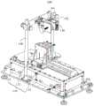
图1为本申请实施例提供的一种焊缝质量检测系统的结构示意图。FIG. 1 is a schematic structural diagram of a welding seam quality detection system provided by an embodiment of the present application.
图2为本申请实施例提供的一种焊缝质量检测系统的示意性结构框图。FIG. 2 is a schematic structural block diagram of a welding seam quality detection system provided by an embodiment of the present application.
图3为本申请实施例提供的一种焊缝质量检测方法的步骤流程图。FIG. 3 is a flow chart of steps of a method for detecting weld seam quality provided by an embodiment of the present application.
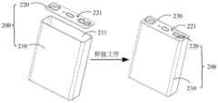
图4为本申请实施例提供的一种动力电池的焊接装配示意图。FIG. 4 is a schematic diagram of welding assembly of a power battery according to an embodiment of the present application.
图5为本申请实施例提供的一种对高度图进行纠偏处理的过程示意图。FIG. 5 is a schematic diagram of a process of performing deviation correction processing on a height map according to an embodiment of the present application.
图6为本申请实施例提供的一种高度图中第一感兴趣区域的位置示意图。FIG. 6 is a schematic diagram of the location of a first region of interest in a height map according to an embodiment of the present application.
图7为本申请实施例提供的一种多条搜索直线的绘制方式示意图。FIG. 7 is a schematic diagram of a drawing manner of multiple search lines according to an embodiment of the present application.
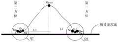
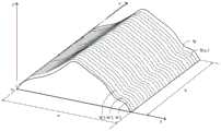
图8为本申请实施例提供的一种目标焊缝的剖面图。FIG. 8 is a cross-sectional view of a target weld provided by an embodiment of the present application.
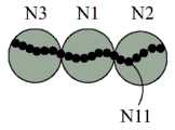
图9为图8中Q1部分的放大图。FIG. 9 is an enlarged view of the portion Q1 in FIG. 8 .
图10为图8中Q2部分的放大图。FIG. 10 is an enlarged view of the portion Q2 in FIG. 8 .
图11为本申请实施例提供的一种扫描窗口的设置示意图。FIG. 11 is a schematic diagram of setting a scanning window according to an embodiment of the present application.
图12为本申请实施例提供的扫描窗口的另一种设置示意图。FIG. 12 is a schematic diagram of another setting of a scan window provided by an embodiment of the present application.
图13为本申请实施例提供的一种子目标焊缝的体积参数计算过程辅助说明图。FIG. 13 is an auxiliary explanatory diagram of a calculation process of a volume parameter of a sub-target weld provided by an embodiment of the present application.
图14为本申请实施例提供的另一种子目标焊缝的体积参数计算过程辅助说明图。FIG. 14 is an auxiliary illustration diagram of another sub-target weld volume parameter calculation process provided by the embodiment of the present application.
图15为本申请实施例提供的扫描窗口的另一种设置示意图。FIG. 15 is a schematic diagram of another setting of a scan window provided by an embodiment of the present application.
图16为本申请实施例提供的一种焊缝质量检测装置的结构示意图。FIG. 16 is a schematic structural diagram of a welding seam quality detection device provided by an embodiment of the present application.
附图标记:100-焊缝质量检测系统;110-运行控制组件;111-基板;112- 滑轨;113-夹具;114-引导控制组件;120-控制器;130-数据采集器;140- 电子设备;150-第一安装架;151-夹持部;200-动力电池;210-电池外壳; 211-开口;220-电池盖板;221-外侧面;230-目标焊缝;300-焊缝质量检测装置;310-图像获取模块;320-定位模块;330-图像分析模块;340-结果获取模块。Reference numerals: 100-weld seam quality inspection system; 110-operation control assembly; 111-substrate; 112-slide rail; 113-fixture; 114-guidance control assembly; 120-controller; 130-data collector; 140- Electronic equipment; 150-first mounting frame; 151-clamping part; 200-power battery; 210-battery casing; 211-opening; 220-battery cover plate; 221-outer side; 230-target welding seam; 300-welding 310-image acquisition module; 320-positioning module; 330-image analysis module; 340-result acquisition module.
具体实施方式Detailed ways
为使本申请实施例的目的、技术方案和优点更加清楚,下面将结合本申请实施例中的附图,对本申请实施例中的技术方案进行描述。此外,应注意到:相似的标号和字母在下面的附图中表示类似项,因此,一旦某一项在一个附图中被定义,则在随后的附图中不需要对其进行进一步定义和解释。In order to make the purposes, technical solutions and advantages of the embodiments of the present application more clear, the technical solutions in the embodiments of the present application will be described below with reference to the accompanying drawings in the embodiments of the present application. Furthermore, it should be noted that like numerals and letters refer to like items in the following figures, so once an item is defined in one figure, it need not be further defined and defined in subsequent figures. explain.
请参阅图1和图2,本申请实施例中,焊缝质量检测系统100包括运行控制组件110、控制器120、数据采集器130和电子设备140,控制器120 分别与运行控制组件110和数据采集器130连接,数据采集器130还与电子设备140连接。Referring to FIGS. 1 and 2 , in this embodiment of the present application, the weld
运行控制组件110用于搭载目标焊接物,并运行。The
本申请实施例中,运行控制组件110可以包括基板111、滑轨112、夹具113和引导控制组件114,其中,滑轨112设置于基板111上,夹具113 设置于滑轨112上,且能够在引导控制组件114的控制作用下,沿滑轨112 的长度方向运行,夹具113用于夹持目标焊接物,且目标焊接物中,焊接侧背离滑轨112。In the embodiment of the present application, the
控制器120用于在运行控制组件110搭载目标焊接物运行至目标位置时,控制数据采集器130采集目标焊接物中,焊接侧的点云数据。The controller 120 is configured to control the
本申请实施例中,控制器120可以是,但不限于可编程逻辑控制器120(Programmable Logic Controller,PLC)。本申请实施例中,控制器120具体可以与引导控制组件114连接,用于在目标焊接物夹持于夹具113,且焊接侧背离滑轨112时,通过引导控制组件114控制夹具113沿滑轨112的长度方向运行,并在夹具113夹持目标焊接物运行至目标位置时,控制数据采集器130采集目标焊接物中,焊接侧的点云数据。此外,本申请实施例中,控制器120可以根据控制组件搭载目标焊接物运行的运行时长和运行速度,判断运行控制组件110是否搭载目标焊接物运行至目标位置。In this embodiment of the present application, the controller 120 may be, but is not limited to, a programmable logic controller 120 (Programmable Logic Controller, PLC). In this embodiment of the present application, the controller 120 may be specifically connected to the
对于数据采集器130,本申请实施例中,其可以是激光轮廓传感器,例如,LMI2520线轮廓传感器。实际实施时,数据采集器130可以通过第一安装架150设置于基板111的上方,具体地,数据采集器130可以夹持于第一安装架150上设置的夹持部151。For the
数据采集器130用于将点云数据发送给电子设备140。The
电子设备140用于获取目标焊接物的点云数据,并将点云数据转换为高度图,从高度图中,确定出用于表征目标焊缝的焊缝区域,对焊缝区域进行分析,获得目标焊缝的特征参数,根据特征参数,获得目标焊缝的质量检测结果,目标焊接物包括基材、焊接件,以及将焊接件焊接于基材上形成的目标焊缝。对于电子设备140,本申请实施例中,其可以是服务器,例如,网络服务器、数据库服务器等,也可以是终端设备,例如,工业计算机,而在结构上,电子设备140可以包括处理器和存储器。The
处理器和存储器直接或间接地电性连接,以实现数据的传输或交互,例如,这些元件相互之间可通过一条或多条通讯总线或信号线实现电性连接。焊缝质量检测装置包括至少一个可以软件或固件(Firmware)的形式存储在存储器中或固化在电子设备140的操作系统(Operating System,OS) 中的软件模块。处理器用于执行存储器中存储的可执行模块,例如,焊缝质量检测装置所包括的软件功能模块及计算机程序等,以实现焊缝质量检测方法。The processor and the memory are electrically connected directly or indirectly to realize data transmission or interaction. For example, these elements can be electrically connected to each other through one or more communication buses or signal lines. The welding seam quality inspection apparatus includes at least one software module that can be stored in a memory or solidified in an operating system (Operating System, OS) of the
处理器可以在接收到执行指令后,执行计算机程序。其中,处理器可以是一种集成电路芯片,具有信号处理能力。处理器也可以是通用处理器,例如,可以是数字信号处理器(Digital Signal Processor,DSP)、专用集成电路(Application Specific IntegratedCircuit,ASIC)、分立门或晶体管逻辑器件、分立硬件组件,可以实现或者执行本申请实施例中的公开的各方法、步骤及逻辑框图,此外,通用处理器可以是微处理器或者任何常规处理器等。The processor may execute the computer program after receiving the execution instructions. The processor may be an integrated circuit chip with signal processing capability. The processor can also be a general-purpose processor, for example, can be a digital signal processor (Digital Signal Processor, DSP), an application specific integrated circuit (Application Specific Integrated Circuit, ASIC), a discrete gate or transistor logic device, a discrete hardware component, which can implement or To execute the methods, steps, and logical block diagrams disclosed in the embodiments of the present application, in addition, the general-purpose processor may be a microprocessor or any conventional processor or the like.
存储器可以是,但不限于,随机存取存储器(Random Access Memory, RAM)、只读存储器(Read Only Memory,ROM)、可编程只读存储器 (Programmable Read-Only Memory,PROM)、可擦可编程序只读存储器 (Erasable Programmable Read-Only Memory,EPROM),以及电可擦编程只读存储器(Electric Erasable Programmable Read-Only Memory,EEPROM)。存储器用于存储程序,处理器在接收到执行指令后,执行该程序。The memory can be, but is not limited to, random access memory (Random Access Memory, RAM), read only memory (Read Only Memory, ROM), programmable read only memory (Programmable Read-Only Memory, PROM), erasable and programmable Program read-only memory (Erasable Programmable Read-Only Memory, EPROM), and Electrical Erasable Programmable Read-Only Memory (Electric Erasable Programmable Read-Only Memory, EEPROM). The memory is used to store the program, and the processor executes the program after receiving the execution instruction.
应当理解,以上描述的结构仅为示意,本申请实施例提供的电子设备 140还可以具有比以上描述内容更少或更多的组件,或是具有与以上描述内容不同的配置。It should be understood that the structure described above is only for illustration, and the
请参阅图3,为本申请实施例提供的焊缝质量检测方法的流程示意图,该方法应用于图2所示的电子设备。所应说明的是,本申请实施例提供的焊缝质量检测方法不以图3及以下所示的顺序为限制,以下结合图3对本申请实施例提供的焊缝质量检测方法的具体流程及步骤进行描述。Please refer to FIG. 3 , which is a schematic flowchart of a welding seam quality detection method provided by an embodiment of the present application, and the method is applied to the electronic device shown in FIG. 2 . It should be noted that the welding seam quality detection method provided by the embodiment of the present application is not limited to the sequence shown in FIG. 3 and the following. The following describes the specific flow and steps of the welding seam quality detection method provided by the embodiment of the present application with reference to FIG. 3 . describe.
步骤S100,获取目标焊接物的点云数据,并将点云数据转换为高度图,目标焊接物包括基材、焊接件,以及将焊接件焊接于基材上形成的目标焊缝。Step S100 , acquiring point cloud data of the target welding object, and converting the point cloud data into a height map. The target welding object includes a base material, a welding piece, and a target weld formed by welding the welding piece on the base material.
本申请实施例中,目标焊接物可以是,但不限于石化、汽车、船舶、电力能源、包装盒制造等工业产品。请结合图4,以目标焊接物为动力电池 200为例,基材可以为电池外壳210,焊接件可以是电池盖板220,而电池外壳210可以呈矩形开口211结构,电池盖板220与电池外壳210中开口 211的形状大小匹配,当电池盖板220安装于电池外壳210的开口211处时,电池盖板220的外侧面221与电池外壳210的开口211处齐平,但还是需要通过焊接工序,将电池盖板220焊接于电池外壳210上,以实现固定,而将电池盖板220焊接于电池外壳210上形成的目标焊缝230,正是位于电池盖板220的外侧面221与电池外壳210的开口211处齐平之后,形成的接合处。In the embodiments of the present application, the target welding object may be, but is not limited to, industrial products such as petrochemicals, automobiles, ships, electric energy, and packaging box manufacturing. Referring to FIG. 4 , taking the target welding object as the
此外,需要说明的是,本申请实施例中,高度图可以理解为点云数据转换的灰度图,针对高度图中的每个像素点,可以根据该像素点的灰度值,获取该像素点的高度值,而像素点的高度值可以理解为目标焊接物上,该像素点所表征位置与数据采集器的距离值。In addition, it should be noted that in this embodiment of the present application, the height map can be understood as a grayscale image converted from point cloud data, and for each pixel in the height map, the pixel can be obtained according to the grayscale value of the pixel. The height value of the point, and the height value of the pixel point can be understood as the distance value between the position represented by the pixel point and the data collector on the target welding object.
步骤S200,从高度图中,确定出用于表征目标焊缝的焊缝区域。Step S200, from the height map, determine the weld area used to characterize the target weld.
本申请实施例中,为提高高度图的图像质量,在执行步骤S200之前,还可以包括步骤S001,对高度图进行预处理,预处理包括滤波处理和/或纠偏处理。In this embodiment of the present application, in order to improve the image quality of the height map, before step S200 is performed, step S001 may be further included to preprocess the height map, and the preprocessing includes filtering processing and/or bias correction processing.
本申请实施例中,滤波处理的方法可以是,但不限于均值滤波、中值滤波、高斯滤波、双边滤波等,以高斯滤波为例,其原理为针对高度图中的每个像素点,通过预设的掩膜版扫描该像素点,并利用掩膜版所在区域内,所有像素点的加权平均灰度值替换位于掩膜版所在区域中心像素点的灰度值,从而平滑高度图,而实际实施时,采用的高斯滤波函数可以是 OpenCV的GaussianBlur函数,掩膜版可以为5*5个像素点。In the embodiments of the present application, the filtering processing method may be, but is not limited to, mean filtering, median filtering, Gaussian filtering, bilateral filtering, etc. Taking Gaussian filtering as an example, the principle is that for each pixel in the height map, through The preset mask scans the pixel, and uses the weighted average gray value of all pixels in the area where the mask is located to replace the gray value of the pixel in the center of the area where the mask is located, thereby smoothing the height map, while In actual implementation, the Gaussian filter function used can be the GaussianBlur function of OpenCV, and the mask can be 5*5 pixels.
对于纠偏处理,本申请实施例中,作为一种可选的实施方式,其可以通过对高度图进行边缘检测,确定出目标焊接物中,焊接侧的边缘直线,获取边缘直线与预设参考线之间的夹角值,再获取参考点,并以参考点为旋转中心,夹角值为旋转角度,获得旋转矩阵,最后,基于旋转矩阵,对高度图进行仿射变换,以实现对高度图的纠偏处理。实际实施时,可以通过Sobel算子,以预设的搜索参数在高度图的第二感兴趣区域内,获取多个焊接物边缘点,再对多个焊接物边缘点进行拟合,确定出目标焊接物中,焊接侧的边缘直线,而预设参考线可以是高度图中任意一条竖直线或水平线,参考点可以是高度图中任一像素点,例如,高度图中目标焊接物所在区域的中心点。For the deviation correction processing, in the embodiment of the present application, as an optional implementation, it can determine the edge straight line on the welding side in the target weld by performing edge detection on the height map, and obtain the edge straight line and the preset reference line The included angle value between them, and then obtain the reference point, and take the reference point as the rotation center, the included angle value is the rotation angle, obtain the rotation matrix, and finally, based on the rotation matrix, perform affine transformation on the height map to realize the height map. correction processing. In actual implementation, the Sobel operator can be used to obtain multiple weld object edge points in the second region of interest of the height map with preset search parameters, and then fit the multiple weld object edge points to determine the target. In the welding object, the edge of the welding side is straight, and the preset reference line can be any vertical or horizontal line in the height map. The reference point can be any pixel point in the height map, for example, the area where the target welding object is located in the height map. the center point.
以图5所示对高度图进行纠偏处理的过程为例,预设参考线为高度图中的竖直线A,参考点为高度图中目标焊接物所在区域的中心点B,以参考点为旋转中心,边缘直线与预设参考线之间的夹角值a为旋转角度,获得旋转矩阵,最后,基于旋转矩阵,对高度图进行仿射变换,以实现对高度图的纠偏处理。Taking the process of correcting the height map shown in FIG. 5 as an example, the preset reference line is the vertical line A in the height map, the reference point is the center point B of the area where the target welding object is located in the height map, and the reference point is The rotation center, the angle value a between the edge straight line and the preset reference line is the rotation angle, and the rotation matrix is obtained. Finally, based on the rotation matrix, affine transformation is performed on the height map to realize the correction processing of the height map.
此外,需要说明的是,本申请实施例中,感兴趣区域是指机器视觉、图像处理过程中,从被处理图像中,以矩形框、圆、椭圆、不规则多边形等形状框架勾勒出的待处理区域。实际实施时,可以通过Halcon、OpenCV、 Matlab等机器视觉软件上常用到各种算子(Operator)和函数来获取第二感兴趣区域。此外,本申请实施例中,多个焊接物边缘点可以是,但不限于3 个、5个、10个,获取到多个焊接物边缘点之后,可以通过最小二乘法对多个焊接物边缘点进行拟合,确定出目标焊接物中,焊接侧的边缘直线。In addition, it should be noted that, in the embodiments of the present application, the region of interest refers to the area to be outlined in the shape of a rectangular frame, a circle, an ellipse, an irregular polygon, etc. from the processed image in the process of machine vision and image processing. processing area. In actual implementation, various operators and functions commonly used in machine vision software such as Halcon, OpenCV, and Matlab can be used to obtain the second region of interest. In addition, in this embodiment of the present application, the number of welding object edge points may be, but not limited to, 3, 5, or 10. After obtaining the multiple welding object edge points, the least squares method can be used to analyze the multiple welding object edge points. Points are fitted to determine the edge straight line on the welding side in the target weld.
通过对高度图进行预处理,能够提高高度图的图像质量,如此,在执行后续步骤200、步骤S300和步骤S400,最终,获得目标焊缝的质量检测结果时,便能够进一步地提高质量检测结果的准确度。By preprocessing the height map, the image quality of the height map can be improved. In this way, when the
而对于步骤S200,本申请实施例中,作为一种可选的实施方式,其可以包括步骤S210、步骤S220和步骤S230。As for step S200, in this embodiment of the present application, as an optional implementation manner, it may include step S210, step S220, and step S230.
步骤S210,从高度图中,选取出第一感兴趣区域。Step S210, from the height map, select a first region of interest.
以图6所示高度图为例,该高度图为目标焊接物中,焊接侧的高度图,也可以理解为,该高度图为目标焊接物的俯视图。此外,本申请实施例中,从高度图中选取出的第一感兴趣区域C可以是矩形框勾勒出的待处理区域,该待处理区域中包括焊接区域图像。Taking the height map shown in FIG. 6 as an example, the height map is a height map of the welding side of the target welding object, and it can also be understood that the height map is a top view of the target welding object. In addition, in this embodiment of the present application, the first region of interest C selected from the height map may be a to-be-processed region outlined by a rectangular frame, and the to-be-processed region includes a welding region image.
步骤S220,根据第一感兴趣区域内多个像素点与预设基准面的高度差值,确定出目标焊缝的第一边缘线和第二边缘线。Step S220: Determine the first edge line and the second edge line of the target weld according to the height difference between the plurality of pixel points in the first region of interest and the preset reference plane.
本申请实施例中,针对第一感兴趣区域内的每个像素点,可以根据该像素点的灰度值,获取该像素点的高度值,该像素点的高度值可以理解为目标焊接物上,该像素点对应位置与数据采集器的距离值,而该像素点与预设基准面的高度差值可以理解为目标焊接物上,该像素点的高度值与预设基准面的高度值之间的差值,同样,可以理解的是,预设基准面的高度值为预设基准面与数据采集器的距离值。进一步地,对于步骤S220,本申请实施例中,作为一种可选的实施方式,其可以包括步骤S221、步骤S222、步骤S223和步骤S224。In the embodiment of the present application, for each pixel in the first region of interest, the height value of the pixel can be obtained according to the gray value of the pixel, and the height value of the pixel can be understood as the height value of the target welding object. , the distance between the corresponding position of the pixel and the data collector, and the height difference between the pixel and the preset reference plane can be understood as the difference between the height of the pixel and the height of the preset reference plane on the target welding object Similarly, it can be understood that the height value of the preset reference plane is the distance value between the preset reference plane and the data collector. Further, for step S220, in this embodiment of the present application, as an optional implementation manner, it may include step S221, step S222, step S223 and step S224.
步骤S221,在第一感兴趣区域内,沿第一方向绘制多条搜索直线,且搜索直线与第一方向垂直,第一方向为第一感兴趣区域的长度方向。Step S221, in the first region of interest, draw a plurality of search lines along a first direction, and the search lines are perpendicular to the first direction, and the first direction is the length direction of the first region of interest.
请参阅图7,本申请实施例中,可以在第一感兴趣区域C内,沿第一方向,以第一预设长度为间隔距离,绘制多条搜索直线D,且搜索直线D 与第一方向垂直,其中,第一方向为第一感兴趣区域C的长度方向,而第一预设长度可以是,但不限于10个像素点、20个像素点、30个像素点。Referring to FIG. 7 , in the embodiment of the present application, a plurality of search lines D may be drawn in the first region of interest C along the first direction with the first preset length as the interval distance, and the search lines D and the first The direction is vertical, wherein the first direction is the length direction of the first region of interest C, and the first preset length may be, but not limited to, 10 pixels, 20 pixels, and 30 pixels.
步骤S222,针对多条搜索直线中的每条搜索直线,根据搜索直线上离散出的多个像素点与预设基准面的高度差值,在搜索直线上确定出目标焊缝的第一边缘点和第二边缘点。Step S222, for each search line in the plurality of search lines, according to the height difference between the plurality of discrete pixel points on the search line and the preset reference plane, determine the first edge point of the target weld on the search line and the second edge point.
对于步骤S222中包括的根据搜索直线上离散出的多个像素点与预设基准面的高度差值,在搜索直线上确定出目标焊缝的第一边缘点和第二边缘点,本申请实施例中,作为一种可选的实施方式,其也可以具体为:针对搜索直线上离散出的多个像素点中的每个像素点,获取像素点与预设基准面的高度差值,从搜索直线上离散出的多个像素点中,获取与预设基准面的高度差值最大的像素点,作为峰值点,此后,从搜索直线上离散出的多个像素点中,选取出位于峰值点的第一方位、与峰值点的距离值满足预设距离要求,且与预设基准面的高度差值最小的像素点,作为第一辅助点,并从第二辅助点与第三辅助点之间选取出与预设基准面的高度差值最小的亚像素点,作为第一边缘点,第二辅助点为与第一辅助点相邻,且位于第一辅助点第一方位的像素点,第三辅助点为与第一辅助点相邻,且位于第一辅助点第二方位的像素点,第二方位与第一方位关于峰值点对称,最后,再从搜索直线上离散出的多个像素点中,选取出位于峰值点的第二方位、与预设基准面的高度差值位于预设高度值区间,且与峰值点的距离值最接近第一边缘点与峰值点距离值的像素点,作为第四辅助点,并从第五辅助点与第六辅助点之间选取出与预设基准面的高度差值最小的亚像素点,作为第二边缘点,第五辅助点为与第四辅助点相邻,且位于第四辅助点第一方位的像素点,第六辅助点为与第四辅助点相邻,且位于第四辅助点第二方位的像素点,其中,预设距离要求、预设高度值区间可以根据目标焊接物的产品要求具体设定,本申请实施例对此不作具体限制。此外,需要说明的是,本申请实施例中,对于第一辅助点与第二辅助点之间划分的亚像素点个数、第一辅助点与第三辅助点之间划分的亚像素点个数、第四辅助点与第五辅助点之间划分的亚像素点个数、第四辅助点与第六辅助点之间划分的亚像素点个数均不作限制。For the height difference between the plurality of pixel points discreted on the search line and the preset reference plane included in step S222, the first edge point and the second edge point of the target weld are determined on the search line, and the present application implements In an example, as an optional implementation, it can also be specifically: for each pixel point in the plurality of pixel points discrete on the search line, obtain the height difference between the pixel point and the preset reference plane, from From the multiple pixels scattered on the search line, the pixel with the largest height difference from the preset reference plane is obtained as the peak point. The first azimuth of the point, the distance value from the peak point meets the preset distance requirements, and the pixel point with the smallest height difference from the preset reference plane is used as the first auxiliary point. The sub-pixel point with the smallest height difference with the preset reference plane is selected as the first edge point, and the second auxiliary point is the pixel point adjacent to the first auxiliary point and located in the first orientation of the first auxiliary point. , the third auxiliary point is a pixel point adjacent to the first auxiliary point and located in the second orientation of the first auxiliary point. The second orientation and the first orientation are symmetrical about the peak point. Among the pixel points, select the second azimuth located at the peak point, the height difference from the preset reference plane is located in the preset height value interval, and the distance value from the peak point is closest to the distance value between the first edge point and the peak point. The pixel point is used as the fourth auxiliary point, and the sub-pixel point with the smallest height difference with the preset reference plane is selected from the fifth auxiliary point and the sixth auxiliary point as the second edge point, and the fifth auxiliary point is The pixel point adjacent to the fourth auxiliary point and located in the first orientation of the fourth auxiliary point, the sixth auxiliary point is the pixel point adjacent to the fourth auxiliary point and located in the second orientation of the fourth auxiliary point, wherein the pre- The distance requirement and the preset height value interval can be specifically set according to the product requirements of the target welding object, which are not specifically limited in the embodiment of the present application. In addition, it should be noted that in this embodiment of the present application, the number of sub-pixel points divided between the first auxiliary point and the second auxiliary point, the number of sub-pixel points divided between the first auxiliary point and the third auxiliary point The number of sub-pixel points divided between the fourth auxiliary point and the fifth auxiliary point, and the number of sub-pixel points divided between the fourth auxiliary point and the sixth auxiliary point are not limited.
需要说明的是,本申请实施例中,第一方位可以是峰值点朝向目标焊缝外侧的方位,也可以是峰值点朝向目标焊缝内侧的方位,若第一方位为峰值点朝向目标焊缝外侧的方位,则第一边缘点为目标焊缝的外侧边缘点,第二边缘点为目标焊缝的内侧边缘点,若第一方位为峰值点朝向目标焊缝内侧的方位,则第一边缘点为目标焊缝的内侧边缘点,第二边缘点为目标焊缝的外侧边缘点。It should be noted that, in the embodiment of the present application, the first orientation may be the orientation with the peak point facing the outside of the target weld, or the orientation with the peak point facing the inside of the target weld. If the first orientation is that the peak point is facing the target weld If the orientation of the outside, the first edge point is the outer edge point of the target weld, the second edge point is the inner edge point of the target weld. The point is the inner edge point of the target weld, and the second edge point is the outer edge point of the target weld.
此外,还需要说明的是,本申请实施例中,预设基准面可以是目标焊接物中焊接件上,高度平缓的区域,以目标焊接物为动力电池为例,预设基准面可以是电池盖板上,高度平缓的区域,也可以理解为,预设基准面可以是电池盖板上,未形成目标焊缝的平缓区域,且该区域与目标焊缝的底部共面。In addition, it should also be noted that, in the embodiment of the present application, the preset reference plane may be an area with a flat height on the welding part of the target welding object. Taking the target welding object as a power battery as an example, the preset reference plane may be a battery The flat area on the cover plate can also be understood as the preset reference plane may be a flat area on the battery cover plate where the target weld is not formed, and the area is coplanar with the bottom of the target weld.
以下,将结合图8、图9和图10,对步骤S222的具体流程及步骤进行进一步描述,其中,图9为图8中Q1部分的放大图,图10为图8中Q2 部分的放大图。Hereinafter, the specific flow and steps of step S222 will be further described with reference to FIG. 8 , FIG. 9 and FIG. 10 , wherein FIG. 9 is an enlarged view of the Q1 part in FIG. 8 , and FIG. 10 is an enlarged view of the Q2 part in FIG. 8 . .
以图7所示的搜索直线D1为例,首先,针对搜索直线D1上离散出的多个像素点中的每个像素点,获取该像素点与预设基准面之间的高度差值。为方便理解,本申请实施例中,可以模拟出图7所示感兴趣区域对应目标焊缝的E-E向剖面图,也即,搜索直线D1位置处对应目标焊缝的剖面图,如图8所示。Taking the search straight line D1 shown in FIG. 7 as an example, first, for each pixel point of the plurality of discrete pixel points on the search line D1, the height difference between the pixel point and the preset reference plane is obtained. For the convenience of understanding, in the embodiment of the present application, the E-E sectional view corresponding to the target weld in the region of interest shown in FIG. 7 can be simulated, that is, the sectional view corresponding to the target weld at the position of the search line D1, as shown in FIG. 8 . Show.
针对搜索直线D1上离散出的多个像素点中的每个像素点,获取该像素点与预设基准面之间的高度差值之后,可以从搜索直线D1上离散出的多个像素点中,获取与预设基准面的高度差值最大的像素点,作为峰值点。为方便描述,本申请实施例中,可以将峰值点记作Nmax。For each pixel point of the plurality of pixel points discreted on the search line D1, after obtaining the height difference between the pixel point and the preset reference plane, it is possible to obtain the height difference value between the pixel point and the preset reference plane. , and obtain the pixel with the largest height difference from the preset reference plane as the peak point. For convenience of description, in this embodiment of the present application, the peak point may be denoted as Nmax.
此后,从搜索直线D1上离散出的多个像素点中,选取出位于峰值点 Nmax的第一方位、与峰值点Nmax的距离值满足预设距离要求,且与预设基准面的高度差值最小的像素点,作为第一辅助点,并从第二辅助点与第三辅助点之间选取出与预设基准面的高度差值最小的亚像素点,作为第一边缘点。以第一方位为峰值点Nmax朝向目标焊缝外侧的方位为例,也即,图7和图8中,峰值点Nmax的右侧方位为例,可以从搜索直线D1上离散出的多个像素点中,选取出位于峰值点Nmax右侧方位,与峰值点Nmax 的距离值满足预设距离要求,且与预设基准面的高度差值最小的像素点,作为第一辅助点,记作N1,再从第二辅助点N2与第三辅助点N3之间选取出与预设基准面的高度差值最小的亚像素点,作为第一边缘点,记作N11。After that, from the plurality of pixels scattered on the search line D1, select the first azimuth located at the peak point Nmax, the distance value from the peak point Nmax meets the preset distance requirement, and the height difference value from the preset reference plane is selected. The smallest pixel point is used as the first auxiliary point, and the sub-pixel point with the smallest height difference with the preset reference plane is selected from the second auxiliary point and the third auxiliary point as the first edge point. Taking the first azimuth as the azimuth of the peak point Nmax facing the outside of the target weld as an example, that is, in Figures 7 and 8, the right azimuth of the peak point Nmax is taken as an example, a plurality of pixels that can be separated from the search line D1 Among the points, select the pixel point located on the right side of the peak point Nmax, the distance value from the peak point Nmax meets the preset distance requirement, and the pixel point with the smallest height difference with the preset reference plane is selected as the first auxiliary point, denoted as N1 , and then select the sub-pixel point with the smallest height difference from the preset reference plane from between the second auxiliary point N2 and the third auxiliary point N3 as the first edge point, denoted as N11.
最后,从搜索直线D1上离散出的多个像素点中,选取出位于峰值点 Nmax的第二方位、与预设基准面的高度差值位于预设高度值区间,且与峰值点Nmax的距离值L1最接近第一边缘点N11与峰值点Nmax距离值的像素点,作为第四辅助点,记作N4,再从第五辅助点N5与第六辅助点N6 之间选取出与预设基准面的高度差值最小的亚像素点,作为第二边缘点,记作N21。Finally, from the plurality of discrete pixels on the search line D1, select the second azimuth located at the peak point Nmax, the height difference from the preset reference plane is located in the preset height value interval, and the distance from the peak point Nmax The pixel point whose value L1 is closest to the distance value between the first edge point N11 and the peak point Nmax is used as the fourth auxiliary point, denoted as N4, and then selected from the fifth auxiliary point N5 and the sixth auxiliary point N6 and the preset reference. The sub-pixel point with the smallest height difference of the surface is used as the second edge point, and is denoted as N21.
步骤S223,对多条搜索直线中,每条搜索直线上的第一边缘点进行拟合,获得目标焊缝的第一边缘线。Step S223: Fitting the first edge points on each of the multiple search straight lines to obtain the first edge line of the target weld.
步骤S224,对多条搜索直线中,每条搜索直线上的第二边缘点进行拟合,获得目标焊缝的第二边缘线。Step S224: Fitting the second edge points on each of the multiple search straight lines to obtain the second edge line of the target weld.
需要说明的是,本申请实施例中,目标焊缝的第一边缘线可以是直线,也可以是曲线,同样,目标焊缝的第二边缘线可以是直线,也可以是曲线,本申请实施例中对此不作具体限制。It should be noted that, in the embodiment of the present application, the first edge line of the target weld may be a straight line or a curve. Similarly, the second edge line of the target weld may be a straight line or a curve. This application implements the There is no specific limitation on this in the example.
步骤S230,将第一边缘线与第二边缘线之间的区域图像,作为表征目标焊缝的焊缝区域。In step S230, the image of the area between the first edge line and the second edge line is used as the weld area representing the target weld.
步骤S300,对焊缝区域进行分析,获得目标焊缝的特征参数。Step S300, analyze the weld area to obtain characteristic parameters of the target weld.
本申请实施例中,目标焊缝的特征参数可以理解为目标焊缝的整体体积参数,而目标焊缝的整体体积参数可以根据焊缝区域内每个像素点与预设基准面的高度差值,利用二重积分计算获得。但为进一步地提高质量检测结果的准确度,对于步骤S300,本申请实施例中,作为一种可选的实施方式,其也可以包括步骤S310、步骤S320和步骤S330。In the embodiment of the present application, the characteristic parameter of the target weld can be understood as the overall volume parameter of the target weld, and the overall volume parameter of the target weld can be based on the height difference between each pixel in the weld area and the preset reference plane , obtained by double integral calculation. However, in order to further improve the accuracy of the quality detection result, for step S300, in this embodiment of the present application, as an optional implementation manner, it may also include step S310, step S320 and step S330.
步骤S310,在焊缝区域上,沿第二方向设置多个扫描窗口,以将焊缝区域划分为多个子区域图像,第二方向为焊缝区域的长度方向。Step S310 , on the weld seam area, set a plurality of scanning windows along a second direction to divide the weld seam area into a plurality of sub-area images, and the second direction is the length direction of the weld seam area.
本申请实施例中,扫描窗口的长度可以根据目标焊接物的产品要求具体设定,本申请实施例对此不作具体限制,此外,本申请实施例中,扫描窗口可以是正方形,也可以为长方形,本申请实施例对此同样不作限制。请结合图11,在设定好扫描窗口的长度之后,可以在焊缝区域上,沿第二方向,以第二预设长度作为步进值,设置多个扫描窗口,分别表征为M1、 M2、M3……Mn-1、Mn,以将焊缝区域划分为多个子区域图像,或请结合图12,在设定好扫描窗口的长度之后,可以在焊缝区域上,沿第二方向,以第二预设长度作为步进值,设置多个扫描窗口,分别表征为M1、M2、 M3……M2n-2、M2n-1,其中,第二方向为焊缝区域的长度方向,第二预设长度可以与扫描窗口的长度相等(如图11所示),也可以是扫描窗口长度的1/2(如图12所示),或其他数值。In the embodiment of the present application, the length of the scanning window may be specifically set according to the product requirements of the target welding object, which is not specifically limited in the embodiment of the present application. In addition, in the embodiment of the present application, the scanning window may be a square or a rectangle. , the embodiments of the present application also do not limit this. Please refer to Fig. 11, after setting the length of the scanning window, you can set a plurality of scanning windows in the welding seam area along the second direction with the second preset length as the step value, which are represented as M1 and M2 respectively. , M3...Mn-1, Mn, to divide the weld area into multiple sub-area images, or please refer to Figure 12, after setting the length of the scanning window, on the weld area, along the second direction, Using the second preset length as the step value, set a plurality of scanning windows, which are respectively represented as M1, M2, M3... M2n-2, M2n-1, wherein the second direction is the length direction of the weld area, and the second The preset length can be equal to the length of the scanning window (as shown in Figure 11 ), or it can be 1/2 of the length of the scanning window (as shown in Figure 12 ), or other values.
步骤S320,针对多个子区域图像中的每个子区域图像,获得子区域图像所表征子目标焊缝的体积参数,以获得多个体积参数。Step S320, for each sub-area image in the plurality of sub-area images, obtain volume parameters of the sub-target welds represented by the sub-area images, so as to obtain a plurality of volume parameters.
本申请实施例中,针对多个子区域图像中的每个子区域图像,可以根据该子区域图像内每个像素点与预设基准面的高度差值,利用二重积分计算该子区域图像所表征的子目标焊缝的体积参数。以图11或图12所示的任意扫描窗口划分的子区域图像为例,可以建立X轴和Y轴位于预设基准面上,且X轴方向为焊缝区域的宽度方向,Y轴方向为第二方向,也即,焊缝区域的长度方向,Z轴垂直于预设基准面的三维坐标系O-XYZ,具体如图13所示,如此,子区域图像中,任意像素点的Z轴坐标值,便为该像素点与预设基准面的高度差值。基于此,对于步骤S320,本申请实施例中,作为第一种可选的实施方式,可以通过以下二重积分计算逻辑,计算该子区域图像所表征的子目标焊缝的体积参数。In the embodiment of the present application, for each sub-area image in the multiple sub-area images, according to the height difference between each pixel in the sub-area image and the preset reference plane, double integral can be used to calculate the representation of the sub-area image. The volume parameter of the sub-target weld. Taking the sub-region image divided by any scanning window shown in Figure 11 or Figure 12 as an example, it can be established that the X-axis and the Y-axis are located on the preset reference plane, and the X-axis direction is the width direction of the weld area, and the Y-axis direction is In the second direction, that is, the length direction of the weld area, the Z axis is perpendicular to the three-dimensional coordinate system O-XYZ of the preset reference plane, as shown in Figure 13. In this way, in the sub-area image, the Z axis of any pixel point The coordinate value is the height difference between the pixel and the preset reference plane. Based on this, for step S320, in this embodiment of the present application, as a first optional implementation, the following double integral calculation logic can be used to calculate the volume parameter of the sub-target weld represented by the sub-region image.

其中,f(x,y)为子目标焊缝在Z轴上的截面积函数,D为积分区域,也即,子区域图像所在的区域。Among them, f(x, y) is the cross-sectional area function of the sub-target weld on the Z axis, and D is the integral area, that is, the area where the sub-area image is located.
请结合图14,对于步骤S320,本申请实施例中,作为第二种可选的实施方式,也可以沿Y轴方向,以一个像素点为单位,将子区域图像划分为多个积分单元,分别表征为W1、W2、W3……Wn-1、Wn,此后,针对每个积分单元,可以通过以下第一积分计算逻辑,计算该积分单元所表征的焊缝单元的体积参数。Please refer to FIG. 14 , for step S320, in this embodiment of the present application, as a second optional implementation manner, the sub-region image may also be divided into a plurality of integration units along the Y-axis direction with a pixel point as a unit, They are respectively represented as W1, W2, W3...Wn-1, Wn. Thereafter, for each integral unit, the volume parameters of the weld unit represented by the integral unit can be calculated by the following first integral calculation logic.

其中,f(x)为焊缝单元在Z轴上的高度函数,a为扫描窗口在X轴方向上的长度值。Among them, f(x) is the height function of the weld element on the Z axis, and a is the length value of the scanning window in the X axis direction.
通过第一积分计算逻辑,获得多个积分单元中,每个积分单元所表征的焊缝单元的体积参数之后,可以通过以下第二积分计算逻辑,计算该子区域图像所表征的子目标焊缝的体积参数。Through the first integral calculation logic, after obtaining the volume parameters of the weld unit represented by each integral unit in the multiple integral units, the sub-target weld represented by the sub-area image can be calculated by the following second integral calculation logic volume parameter.

其中,f(y)为沿Y轴方向,积分单元所表征的焊缝单元的体积参数,也可以理解为,f(y)为子目标焊缝在Y轴上的截面积函数,b为扫描窗口在Y 轴方向上的长度值。Among them, f(y) is the volume parameter of the weld element represented by the integral unit along the Y-axis direction. It can also be understood that f(y) is the cross-sectional area function of the sub-target weld on the Y-axis, and b is the scan The length of the window in the Y-axis direction.
步骤S330,将多个体积参数中数值最小的体积参数,作为目标焊缝的特征参数。Step S330, taking the volume parameter with the smallest value among the multiple volume parameters as the characteristic parameter of the target weld.
需要说明的是,若第二预设长度为扫描窗口长度的1/2或更小的数值,则可以将多个体积参数中数值最小的体积参数,直接作为目标焊缝的特征参数,若第二预设长度与扫描窗口的长度相等,则可以在执行步骤S310和步骤S320而获得多个体积参数之后,以执行步骤S310时,获得的第一个扫描窗口的中心位置为窗口起始位置,再次沿第二方向设置多个扫描窗口,以将焊缝区域划分为多个子区域图像,并针对多个子区域图像中的每个子区域图像,获得子区域图像所表征子目标焊缝的体积参数,以再次获得多个体积参数,第一次获得多个体积参数过程中设置多个扫描窗口,分别表征为M1、M2、M3……Mn-1、Mn,以及第二次获得多个体积参数过程中设置多个扫描窗口,分别表征为M'1、M'2、M'3……M'n-1、M'n,如图15 所示,最后,将两次获得的多个体积参数中数值最小的体积参数,作为目标焊缝的特征参数。It should be noted that if the second preset length is 1/2 or less of the length of the scanning window, the volume parameter with the smallest value among the multiple volume parameters can be directly used as the characteristic parameter of the target weld. 2. The preset length is equal to the length of the scanning window, then after step S310 and step S320 are performed to obtain a plurality of volume parameters, the center position of the first scanning window obtained when step S310 is performed is the starting position of the window, A plurality of scanning windows are set along the second direction again to divide the weld area into a plurality of sub-area images, and for each sub-area image in the plurality of sub-area images, the volume parameters of the sub-target welds represented by the sub-area images are obtained, In order to obtain multiple volume parameters again, multiple scan windows are set in the process of obtaining multiple volume parameters for the first time, which are respectively characterized as M1, M2, M3...Mn-1, Mn, and the second process of obtaining multiple volume parameters Set up multiple scanning windows in M'1, M'2, M'3... The volume parameter with the smallest value is used as the characteristic parameter of the target weld.
步骤S400,根据特征参数,获得目标焊缝的质量检测结果。Step S400, obtaining the quality inspection result of the target weld according to the characteristic parameters.
对于步骤S400,本申请实施例中,作为第一种可选的实施方式,其可以通过判断特征参数是否位于预设参数范围内,若特征参数位于预设参数范围内,则目标焊缝的质量检测结果为合格,若特征参数超出预设参数范围内,则目标焊缝的质量检测结果为不合格。其中,预设参数范围可以根据目标焊接物的产品要求具体设定,本申请实施例对此不作具体限制。For step S400, in the embodiment of the present application, as a first optional implementation, it can judge whether the characteristic parameter is within the preset parameter range, and if the characteristic parameter is within the preset parameter range, the quality of the target weld The test result is qualified, and if the characteristic parameters exceed the preset parameter range, the quality test result of the target weld is unqualified. The preset parameter range may be specifically set according to the product requirements of the target welding object, which is not specifically limited in the embodiment of the present application.
为进一步提高质量检测结果的准确度,对于步骤S400,本申请实施例中,作为第二种可选的实施方式,其也可以通过将特征参数输入预设的分类模型,并获得分类模型的输出结果实现,而输出结果包括用于表征目标焊缝的质量检测结果为合格的第一结果,以及用于表征目标焊缝的质量检测结果为不合格的第二结果。In order to further improve the accuracy of the quality detection result, for step S400, in this embodiment of the present application, as a second optional implementation, it can also input the feature parameters into a preset classification model, and obtain the output of the classification model. The result is achieved, and the output result includes a first result for characterizing the quality inspection result of the target weld as acceptable, and a second result for characterizing the quality inspection result for the target weld as unqualified.
基于以上描述,本申请实施例提供的焊缝质量检测方法,在将特征参数输入预设的分类模型,并获得分类模型的输出结果之前,还可以包括:获取第一目标数量个标准焊接物中,每个标准焊接物包括的标准焊缝的特征参数,作为标准参数,以获得第一目标数量条标准参数,获取第二目标数量个次品焊接物中,每个次品焊接物包括的不合格焊缝的特征参数,作为不合格参数,以获得第二目标数量条不合格参数,以及通过第一目标数量条标准参数和第二目标数量条不合格参数,对初始学习模型进行训练,获得分类模型,需要说明的是,再对初始学习模型进行训练的过程中,还将运用到每个标准焊接物中,标准焊缝的焊缝区域轮廓参数,以及每个次品焊接物中,不合格焊缝的焊缝区域轮廓参数。此外,本申请实施例中,初始学习模型可以是支持向量机(Support Vector Machine,SVM)。Based on the above description, in the weld quality detection method provided by the embodiment of the present application, before inputting the characteristic parameters into the preset classification model and obtaining the output result of the classification model, the method may further include: obtaining a first target number of standard welds , the characteristic parameters of the standard welds included in each standard weld are used as standard parameters to obtain the first target quantity of standard parameters, and to obtain the second target quantity of defective welds, each defective weld includes different The characteristic parameters of qualified welds are used as unqualified parameters to obtain the second target number of unqualified parameters, and the initial learning model is trained through the first target number of standard parameters and the second target number of unqualified parameters to obtain The classification model, it should be noted that, in the process of training the initial learning model, it will also be applied to each standard weld, the weld area contour parameters of the standard weld, and each defective weld. Weld area profile parameters for qualified welds. In addition, in this embodiment of the present application, the initial learning model may be a support vector machine (Support Vector Machine, SVM).
基于与上述焊缝质量检测方法同样的发明构思,本申请实施例还提供了一种焊缝质量检测装置300。请参阅图16,本申请实施例提供的焊缝质量检测装置300包括图像获取模块310、定位模块320、图像分析模块330 和结果获取模块340。Based on the same inventive concept as the above-mentioned welding seam quality detection method, an embodiment of the present application further provides a welding seam
图像获取模块310,用于获取目标焊接物的点云数据,并将点云数据转换为高度图,目标焊接物包括基材、焊接件,以及将焊接件焊接于基材上形成的目标焊缝。The
关于图像获取模块310的描述具体可参考对图3中所示的步骤S100的详细描述,也即,步骤S100可以由图像获取模块310执行。For the description of the
定位模块320,用于从高度图中,确定出用于表征目标焊缝的焊缝区域。The
关于定位模块320的描述具体可参考对图3中所示的步骤S200的详细描述,也即,步骤S200可以由定位模块320执行。For the description of the
图像分析模块330,用于对焊缝区域进行分析,获得目标焊缝的特征参数。The
关于图像分析模块330的描述具体可参考对图3中所示的步骤S300的详细描述,也即,步骤S300可以由图像分析模块330执行。For the description of the
结果获取模块340,用于根据特征参数,获得目标焊缝的质量检测结果。The
根据特征参数,获得目标焊缝的质量检测结果,可以包括:According to the characteristic parameters, the quality inspection result of the target weld is obtained, which can include:
判断特征参数是否位于预设参数范围内;Determine whether the characteristic parameters are within the preset parameter range;
若特征参数位于预设参数范围内,则目标焊缝的质量检测结果为合格;If the characteristic parameters are within the preset parameter range, the quality inspection result of the target weld is qualified;
若特征参数超出预设参数范围内,则目标焊缝的质量检测结果为不合格。If the characteristic parameters exceed the preset parameter range, the quality inspection result of the target weld is unqualified.
判断特征参数是否位于预设参数范围内,也可以包括:Judging whether the characteristic parameters are within the preset parameter range can also include:
将特征参数输入预设的分类模型,并获得分类模型的输出结果,输出结果包括用于表征目标焊缝的质量检测结果为合格的第一结果,以及用于表征目标焊缝的质量检测结果为不合格的第二结果。Input the characteristic parameter into the preset classification model, and obtain the output result of the classification model, the output result includes the first result used to characterize the quality inspection result of the target weld as qualified, and the quality inspection result used to characterize the target weld as Unqualified secondary results.
基于此,将特征参数输入预设的分类模型,并获得分类模型的输出结果之前,焊缝质量检测方法,还包括:Based on this, before inputting the feature parameters into the preset classification model and obtaining the output result of the classification model, the welding seam quality detection method also includes:
获取第一目标数量个标准焊接物中,每个标准焊接物包括的标准焊缝的特征参数,作为标准参数,以获得第一目标数量条标准参数;Acquire the characteristic parameters of the standard welds included in each of the standard welds in the first target quantity of standard welds as standard parameters, so as to obtain the first target quantity of standard parameters;
获取第二目标数量个次品焊接物中,每个次品焊接物包括的不合格焊缝的特征参数,作为不合格参数,以获得第二目标数量条不合格参数;Acquiring the second target quantity of defective welds, the characteristic parameters of the unqualified welds included in each defective weld, as unqualified parameters, to obtain the second target quantity of unqualified parameters;
通过第一目标数量条标准参数和第二目标数量条不合格参数,对初始学习模型进行训练,获得分类模型。The initial learning model is trained by using the standard parameters of the first target quantity and the unqualified parameters of the second target quantity to obtain a classification model.
关于结果获取模块340的描述具体可参考对图3中所示的步骤S400的详细描述,也即,步骤S400可以由结果获取模块340执行。For the description of the
本申请实施例提供的焊缝质量检测装置300,还可以包括预处理模块。The welding seam
预处理模块,用于对高度图进行预处理,预处理包括滤波处理和/或纠偏处理。The preprocessing module is used to preprocess the height map, and the preprocessing includes filtering processing and/or bias correction processing.
预处理包括纠偏处理,对高度图进行预处理,可以包括:Preprocessing includes bias correction processing, and preprocessing the height map, which can include:
对高度图进行边缘检测,确定出目标焊接物中,焊接侧的边缘直线;Perform edge detection on the height map to determine the edge straight line on the welding side of the target weld;
获取边缘直线与预设参考线之间的夹角值;Get the angle value between the edge line and the preset reference line;
获取参考点,并以参考点为旋转中心,夹角值为旋转角度,获得旋转矩阵;Obtain the reference point, and take the reference point as the rotation center, the included angle value is the rotation angle, and obtain the rotation matrix;
基于旋转矩阵,对高度图进行仿射变换,以实现对高度图的纠偏处理。Based on the rotation matrix, perform affine transformation on the height map to realize the correction processing of the height map.
关于预处理模块的描述具体可参考上述焊缝质量检测方法相关实施例中关于步骤S001的详细描述,也即,步骤S001可以由预处理模块执行。For the description of the preprocessing module, reference may be made to the detailed description of step S001 in the above-mentioned related embodiments of the welding seam quality detection method, that is, step S001 may be executed by the preprocessing module.
本申请实施例中,定位模块320可以包括区域选取单元、边缘线确定单元和图像获取单元。In this embodiment of the present application, the
区域选取单元,用于从高度图中,选取出第一感兴趣区域。The region selection unit is used to select the first region of interest from the height map.
关于区域选取单元的描述具体可参考上述焊缝质量检测方法相关实施例中关于步骤S210的详细描述,也即,步骤S210可以由区域选取单元执行。For the description of the area selection unit, reference may be made to the detailed description of step S210 in the above-mentioned related embodiments of the welding seam quality detection method, that is, step S210 may be performed by the area selection unit.
边缘线确定单元,用于根据第一感兴趣区域内多个像素点与预设基准面的高度差值,确定出目标焊缝的第一边缘线和第二边缘线。The edge line determining unit is configured to determine the first edge line and the second edge line of the target weld according to the height difference between the plurality of pixel points in the first region of interest and the preset reference plane.
关于边缘线确定单元的描述具体可参考上述焊缝质量检测方法相关实施例中关于步骤S220的详细描述,也即,步骤S220可以由边缘线确定单元执行。For the description of the edge line determination unit, reference may be made to the detailed description of step S220 in the above-mentioned related embodiments of the welding seam quality detection method, that is, step S220 may be performed by the edge line determination unit.
图像获取单元,用于将第一边缘线与第二边缘线之间的区域图像,作为表征目标焊缝的焊缝区域。The image acquisition unit is configured to use the image of the area between the first edge line and the second edge line as the weld area representing the target weld.
关于图像获取单元的描述具体可参考上述焊缝质量检测方法相关实施例中关于步骤S230的详细描述,也即,步骤S230可以由图像获取单元执行。For the description of the image acquisition unit, reference may be made to the detailed description of step S230 in the above-mentioned related embodiments of the welding seam quality detection method, that is, step S230 may be performed by the image acquisition unit.
本申请实施例中,边缘线确定单元可以包括绘制子单元、边缘点确定子单元、第一边缘线确定子单元和第二边缘线确定子单元。In this embodiment of the present application, the edge line determination unit may include a drawing subunit, an edge point determination subunit, a first edge line determination subunit, and a second edge line determination subunit.
绘制子单元,用于在第一感兴趣区域内,沿第一方向绘制多条搜索直线,且搜索直线与第一方向垂直,第一方向为第一感兴趣区域的长度方向。The drawing subunit is used for drawing a plurality of search lines along a first direction in the first region of interest, and the search lines are perpendicular to the first direction, and the first direction is the length direction of the first region of interest.
关于绘制子单元的描述具体可参考上述焊缝质量检测方法相关实施例中关于步骤S221的详细描述,也即,步骤S221可以由绘制子单元执行。For the description of the drawing subunit, reference may be made to the detailed description of step S221 in the above-mentioned related embodiments of the welding seam quality detection method, that is, step S221 may be performed by the drawing subunit.
边缘点确定子单元,用于针对多条搜索直线中的每条搜索直线,根据搜索直线上离散出的多个像素点与预设基准面的高度差值,在搜索直线上确定出目标焊缝的第一边缘点和第二边缘点。The edge point determination sub-unit is used to determine the target weld on the search line according to the height difference between the plurality of discrete pixel points on the search line and the preset reference plane for each search line in the search line The first edge point and the second edge point of .
根据搜索直线上离散出的多个像素点与预设基准面的高度差值,在搜索直线上确定出目标焊缝的第一边缘点和第二边缘点,可以包括:Determine the first edge point and the second edge point of the target weld on the search line according to the height difference between the plurality of discrete pixel points on the search line and the preset reference plane, which may include:
针对搜索直线上离散出的多个像素点中的每个像素点,获取像素点与预设基准面的高度差值;For each pixel point in the plurality of pixel points discreted on the search line, obtain the height difference between the pixel point and the preset reference plane;
从搜索直线上离散出的多个像素点中,获取与预设基准面的高度差值最大的像素点,作为峰值点;Obtain the pixel point with the largest height difference from the preset reference plane from the plurality of pixel points discreted on the search line as the peak point;
从搜索直线上离散出的多个像素点中,选取出位于峰值点的第一方位、与峰值点的距离值满足预设距离要求,且与预设基准面的高度差值最小的像素点,作为第一辅助点,并从第二辅助点与第三辅助点之间选取出与预设基准面的高度差值最小的亚像素点,作为第一边缘点,第二辅助点为与第一辅助点相邻,且位于第一辅助点第一方位的像素点,第三辅助点为与第一辅助点相邻,且位于第一辅助点第二方位的像素点,第二方位与第一方位关于峰值点对称;From the plurality of pixel points discreted on the search line, select the pixel point located in the first azimuth of the peak point, the distance value from the peak point meets the preset distance requirement, and the pixel point with the smallest height difference from the preset reference plane, As the first auxiliary point, the sub-pixel point with the smallest height difference with the preset reference plane is selected from the second auxiliary point and the third auxiliary point as the first edge point, and the second auxiliary point is the same as the first edge point. The auxiliary point is adjacent to the pixel point located in the first orientation of the first auxiliary point, and the third auxiliary point is the pixel point adjacent to the first auxiliary point and located in the second orientation of the first auxiliary point, and the second orientation is the same as the first auxiliary point. Azimuth is symmetrical about the peak point;
从搜索直线上离散出的多个像素点中,选取出位于峰值点的第二方位、与预设基准面的高度差值位于预设高度值区间,且与峰值点的距离值最接近第一边缘点与峰值点距离值的像素点,作为第四辅助点,并从第五辅助点与第六辅助点之间选取出与预设基准面的高度差值最小的亚像素点,作为第二边缘点,第五辅助点为与第四辅助点相邻,且位于第四辅助点第一方位的像素点,第六辅助点为与第四辅助点相邻,且位于第四辅助点第二方位的像素点。From the plurality of pixel points scattered on the search line, select the second azimuth located at the peak point, the height difference from the preset reference plane is located in the preset height value range, and the distance value from the peak point is closest to the first The pixel point of the distance value between the edge point and the peak point is used as the fourth auxiliary point, and the sub-pixel point with the smallest height difference with the preset reference plane is selected from the fifth auxiliary point and the sixth auxiliary point as the second auxiliary point. Edge point, the fifth auxiliary point is a pixel point adjacent to the fourth auxiliary point and located in the first orientation of the fourth auxiliary point, and the sixth auxiliary point is adjacent to the fourth auxiliary point and is located in the second auxiliary point of the fourth auxiliary point. Azimuth in pixels.
关于边缘点确定子单元的描述具体可参考上述焊缝质量检测方法相关实施例中关于步骤S222的详细描述,也即,步骤S222可以由边缘点确定子单元执行。For the description of the edge point determination subunit, reference may be made to the detailed description of step S222 in the above-mentioned related embodiments of the welding seam quality detection method, that is, step S222 may be performed by the edge point determination subunit.
第一边缘线确定子单元,用于对多条搜索直线中,每条搜索直线上的第一边缘点进行拟合,获得目标焊缝的第一边缘线。The first edge line determination subunit is used for fitting the first edge points on each search line among the multiple search lines to obtain the first edge line of the target weld.
关于第一边缘线确定子单元的描述具体可参考上述焊缝质量检测方法相关实施例中关于步骤S223的详细描述,也即,步骤S223可以由第一边缘线确定子单元执行。For the description of the first edge line determination subunit, reference may be made to the detailed description of step S223 in the above-mentioned related embodiments of the welding seam quality detection method, that is, step S223 may be performed by the first edge line determination subunit.
第二边缘线确定子单元,用于对多条搜索直线中,每条搜索直线上的第二边缘点进行拟合,获得目标焊缝的第二边缘线。The second edge line determination subunit is used for fitting the second edge points on each search line among the multiple search lines to obtain the second edge line of the target weld.
关于第二边缘线确定子单元的描述具体可参考上述焊缝质量检测方法相关实施例中关于步骤S224的详细描述,也即,步骤S224可以由第二边缘线确定子单元执行。For the description of the second edge line determination subunit, reference may be made to the detailed description of step S224 in the above-mentioned related embodiments of the welding seam quality detection method, that is, step S224 may be performed by the second edge line determination subunit.
本申请实施例中,图像分析模块330可以包括窗口设置单元、第一参数获取单元和第二参数获取单元。In this embodiment of the present application, the
窗口设置单元,用于在焊缝区域上,沿第二方向设置多个扫描窗口,以将焊缝区域划分为多个子区域图像,第二方向为焊缝区域的长度方向。The window setting unit is used for setting a plurality of scanning windows along the second direction on the weld area, so as to divide the weld area into a plurality of sub-area images, and the second direction is the length direction of the weld area.
关于窗口设置单元的描述具体可参考上述焊缝质量检测方法相关实施例中关于步骤S310的详细描述,也即,步骤S310可以由窗口设置单元执行。For the description of the window setting unit, reference may be made to the detailed description of step S310 in the above-mentioned related embodiments of the welding seam quality detection method, that is, step S310 may be performed by the window setting unit.
第一参数获取单元,用于针对多个子区域图像中的每个子区域图像,获得子区域图像所表征子目标焊缝的体积参数,以获得多个体积参数。The first parameter obtaining unit is configured to obtain, for each sub-region image in the plurality of sub-region images, volume parameters of the sub-target welds represented by the sub-region images, so as to obtain a plurality of volume parameters.
获得子区域图像所表征的子目标焊缝的体积参数,可以包括:Obtain the volume parameters of the sub-target weld represented by the sub-region image, which can include:
根据子区域图像内每个像素点与预设基准面的高度差值,利用二重积分计算子区域图像所表征的子目标焊缝的体积参数。According to the height difference between each pixel in the sub-area image and the preset reference plane, the volume parameter of the sub-target weld represented by the sub-area image is calculated by double integral.
关于第一参数获取单元的描述具体可参考上述焊缝质量检测方法相关实施例中关于步骤S320的详细描述,也即,步骤S320可以由第一参数获取单元执行。For the description of the first parameter acquisition unit, reference may be made to the detailed description of step S320 in the above-mentioned related embodiments of the welding seam quality detection method, that is, step S320 may be performed by the first parameter acquisition unit.
第二参数获取单元,用于将多个体积参数中数值最小的体积参数,作为目标焊缝的特征参数。The second parameter obtaining unit is used for taking the volume parameter with the smallest value among the multiple volume parameters as the characteristic parameter of the target weld.
关于第二参数获取单元的描述具体可参考上述焊缝质量检测方法相关实施例中关于步骤S330的详细描述,也即,步骤S330可以由第二参数获取单元执行。For the description of the second parameter acquisition unit, reference may be made to the detailed description of step S330 in the above-mentioned related embodiments of the welding seam quality detection method, that is, step S330 may be performed by the second parameter acquisition unit.
此外,本申请实施例还提供了一种计算机可读存储介质,计算机可读存储介质上存储有计算机程序,计算机程序被执行时,实现上述方法实施例所提供的焊缝质量检测方法,具体可参见上述方法实施例,本申请实施例中对此不作赘述。In addition, the embodiments of the present application also provide a computer-readable storage medium, where a computer program is stored on the computer-readable storage medium, and when the computer program is executed, the welding seam quality detection method provided by the above method embodiment is implemented. Refer to the foregoing method embodiments, which are not repeated in the embodiments of the present application.
综上所述,本申请实施例提供的焊缝质量检测方法、装置、系统及电子设备,通过获取目标焊接物的点云数据,并将点云数据转换为高度图,从高度图中,确定出用于表征目标焊缝的焊缝区域,再对焊缝区域进行分析,获得目标焊缝的特征参数,最后,根据特征参数,获得目标焊缝的质量检测结果,其中,目标焊接物包括基材、焊接件,以及将焊接件焊接于基材上形成的目标焊缝。相对于现有技术中,采用人工检测的方法对焊缝质量进行检测的方案而言,本申请实施例提供的焊缝质量检测方法、装置、系统及电子设备基于机器视觉技术,获得目标焊缝的质量检测结果,避免了人工参与,因此,能够提高质量检测结果的准确度,例如,本申请实施例提供的焊缝质量检测方法能够应用于周边焊的焊缝质量检测,以检测出面积大于0.5mm2,深度大于0.2mm的焊缝缺陷,具有较强的实际应用价值。To sum up, the welding seam quality detection method, device, system and electronic equipment provided by the embodiments of the present application obtain the point cloud data of the target welding object, convert the point cloud data into a height map, and determine from the height map. Obtain the weld area used to characterize the target weld, then analyze the weld area to obtain the characteristic parameters of the target weld, and finally, according to the characteristic parameters, obtain the quality inspection result of the target weld, wherein the target weld includes material, weldments, and target welds formed by welding weldments to substrates. Compared with the solution in the prior art that uses the manual detection method to detect the weld seam quality, the weld seam quality detection method, device, system and electronic device provided by the embodiments of the present application are based on machine vision technology to obtain the target weld seam. Therefore, the accuracy of the quality inspection results can be improved. For example, the welding seam quality inspection method provided in the embodiment of the present application can be applied to the welding seam quality inspection of peripheral welding, so that the detected area is larger than 0.5mm2 , weld defects with a depth greater than 0.2mm have strong practical application value.
在本申请几个实施例中,应当理解到,所揭露的焊缝质量检测方法和装置,也可以通过其它的方式实现,而以上所描述的焊缝质量检测装置实施例仅仅是示意性的,例如,附图中的流程图和框图显示了根据本申请的多个实施例的装置、方法和计算机程序产品可能实现的体系架构、功能和操作。在这点上,流程图或框图中的每个方框可以代表一个模块、程序段或代码的一部分,所述模块、程序段或代码的一部分包含一个或多个用于实现规定的逻辑功能的可执行指令。此外,在有些作为替换的实现方式中,方框中所标注的功能也可以以不同于附图中所标注的顺序发生。例如,两个连续的方框实际上可以并行地执行,它们有时也可以按相反的顺序执行,这将根据所涉及的功能而定。还应当注意的是,框图和/或流程图中的每个方框、以及框图和/或流程图中方框的组合,可以用执行规定的功能或动作的专用的基于硬件的系统来实现,或者可以用专用硬件与计算机指令的组合来实现。此外,在本申请每个实施例中,各功能模块可以集成在一起形成一个独立的部分,也可以是每个模块单独存在,也可以多个模块集成形成一个独立的部分。In several embodiments of the present application, it should be understood that the disclosed method and device for detecting weld seam quality can also be implemented in other ways, and the above-described embodiments of the device for detecting weld seam quality are merely illustrative. For example, the flowchart and block diagrams in the Figures illustrate the architecture, functionality, and operation of possible implementations of apparatus, methods and computer program products according to various embodiments of the present application. In this regard, each block in the flowchart or block diagrams may represent a module, segment, or portion of code that contains one or more functions for implementing the specified logical function(s) executable instructions. Furthermore, in some alternative implementations, the functions noted in the blocks may occur out of the order noted in the figures. For example, two blocks in succession may, in fact, be executed in parallel, or the blocks may sometimes be executed in the reverse order, depending upon the functionality involved. It should also be noted that each block of the block diagrams and/or flowchart illustrations, and combinations of blocks in the block diagrams and/or flowchart illustrations, can be implemented in dedicated hardware-based systems that perform the specified functions or actions, or It may be implemented in a combination of special purpose hardware and computer instructions. In addition, in each embodiment of the present application, each functional module may be integrated together to form an independent part, or each module may exist independently, or multiple modules may be integrated to form an independent part.
此外,所述功能如果以软件功能模块的形式实现,并作为独立的产品销售或使用时,可以存储在一个计算机可读取存储介质中。基于这样的理解,本申请的技术方案本质上或者说对现有技术做出贡献的部分或者该技术方案的部分可以以软件产品的形式体现出来,该计算机软件产品存储在一个存储介质中,包括若干指令用以使得一台计算机设备(可以是个人计算机,服务器,或者网络设备等)执行本申请每个实施例所述方法的全部或部分步骤。而前述的存储介质包括:U盘、移动硬盘、ROM、RAM、磁碟或者光盘等各种可以存储程序代码的介质。In addition, if the functions are implemented in the form of software function modules and sold or used as independent products, they may be stored in a computer-readable storage medium. Based on this understanding, the technical solution of the present application can be embodied in the form of a software product in essence, or the part that contributes to the prior art or the part of the technical solution. The computer software product is stored in a storage medium, including Several instructions are used to cause a computer device (which may be a personal computer, a server, or a network device, etc.) to execute all or part of the steps of the method described in each embodiment of the present application. The aforementioned storage medium includes: a U disk, a removable hard disk, a ROM, a RAM, a magnetic disk, or an optical disk and other mediums that can store program codes.
还需要说明的是,在本申请文件中,诸如“第一”、“第二”、“第三”等之类的关系术语仅仅用来将一个实体或者操作与另一个实体或操作区分开来,而不一定要求或者暗示这些实体或操作之间存在任何这种实际的关系或者顺序,而术语“包括”、“包含”或者其任何其他变体意在涵盖非排他性的包含,从而使得包括一系列要素的过程、方法、物品或者设备不仅包括那些要素,而且还包括没有明确列出的其他要素,或者是还包括为这种过程、方法、物品或者设备所固有的要素。It should also be noted that in this application document, relational terms such as "first", "second", "third", etc. are only used to distinguish one entity or operation from another entity or operation , without necessarily requiring or implying the existence of any such actual relationship or order between these entities or operations, and the terms "comprising", "comprising" or any other variation thereof are intended to encompass a non-exclusive inclusion such that including a A process, method, article or apparatus of a series of elements includes not only those elements, but also other elements not expressly listed, or elements inherent to such process, method, article or apparatus.
Claims (12)
Translated fromChinesePriority Applications (4)
| Application Number | Priority Date | Filing Date | Title |
|---|---|---|---|
| CN202010313058.7ACN111462110B (en) | 2020-04-20 | 2020-04-20 | Weld quality inspection method, device, system and electronic equipment |
| US17/917,947US12394035B2 (en) | 2020-04-20 | 2021-04-14 | Weld quality inspection method, apparatus and system, and electronic device |
| PCT/CN2021/087111WO2021213223A1 (en) | 2020-04-20 | 2021-04-14 | Weld quality inspection method, apparatus and system, and electronic device |
| DE112021000013.6TDE112021000013T5 (en) | 2020-04-20 | 2021-04-14 | Process, device and system for quality inspection of a weld seam as well as electronic system |
Applications Claiming Priority (1)
| Application Number | Priority Date | Filing Date | Title |
|---|---|---|---|
| CN202010313058.7ACN111462110B (en) | 2020-04-20 | 2020-04-20 | Weld quality inspection method, device, system and electronic equipment |
Publications (2)
| Publication Number | Publication Date |
|---|---|
| CN111462110Atrue CN111462110A (en) | 2020-07-28 |
| CN111462110B CN111462110B (en) | 2021-04-13 |
Family
ID=71685956
Family Applications (1)
| Application Number | Title | Priority Date | Filing Date |
|---|---|---|---|
| CN202010313058.7AActiveCN111462110B (en) | 2020-04-20 | 2020-04-20 | Weld quality inspection method, device, system and electronic equipment |
Country Status (4)
| Country | Link |
|---|---|
| US (1) | US12394035B2 (en) |
| CN (1) | CN111462110B (en) |
| DE (1) | DE112021000013T5 (en) |
| WO (1) | WO2021213223A1 (en) |
Cited By (28)
| Publication number | Priority date | Publication date | Assignee | Title |
|---|---|---|---|---|
| CN112067633A (en)* | 2020-09-10 | 2020-12-11 | 张晓锋 | Steel construction building engineering quality intelligent detection system based on machine vision |
| CN112183555A (en)* | 2020-09-23 | 2021-01-05 | 唐山松下产业机器有限公司 | Method and system for detecting welding quality, electronic device and storage medium |
| CN112200786A (en)* | 2020-10-15 | 2021-01-08 | 福建工程学院 | A kind of extraction method of pole welding annular area |
| CN112561854A (en)* | 2020-11-11 | 2021-03-26 | 深圳大学 | Welding seam detection method based on line structure light point cloud |
| CN112692406A (en)* | 2020-12-14 | 2021-04-23 | 深圳市瑞凌实业股份有限公司 | Welding line energy acquisition device and method |
| WO2021213223A1 (en)* | 2020-04-20 | 2021-10-28 | 广东利元亨智能装备股份有限公司 | Weld quality inspection method, apparatus and system, and electronic device |
| CN113610814A (en)* | 2021-08-10 | 2021-11-05 | 广东利元亨智能装备股份有限公司 | Weld quality detection method and device, electronic equipment and storage medium |
| CN114061509A (en)* | 2021-11-16 | 2022-02-18 | 珠海格力智能装备有限公司 | Remote controller detection method, device, equipment, storage medium and processor |
| CN114083184A (en)* | 2021-11-29 | 2022-02-25 | 西安万硕电子科技有限公司 | Full-automatic welding equipment and method for bent cap framework piece |
| CN114092438A (en)* | 2021-11-18 | 2022-02-25 | 武汉逸飞激光股份有限公司 | Method, device, electronic equipment and storage medium for welding quality detection of soft-packed cell |
| CN114119470A (en)* | 2021-10-15 | 2022-03-01 | 厦门微亚智能科技有限公司 | Electric core seal nail weld appearance detection algorithm and system based on deep learning |
| CN114119497A (en)* | 2021-11-04 | 2022-03-01 | 武汉逸飞激光股份有限公司 | Method and device for detecting sealing welding quality of cylindrical battery cell, electronic equipment and storage medium |
| CN114147389A (en)* | 2021-11-05 | 2022-03-08 | 江苏三沃电子科技有限公司 | Welding auxiliary method and system for detecting welding process parameters |
| CN114193029A (en)* | 2020-09-18 | 2022-03-18 | 宝山钢铁股份有限公司 | Welding machine weld joint pre-evaluation method based on big data analysis model |
| CN114354618A (en)* | 2021-12-16 | 2022-04-15 | 浙江大华技术股份有限公司 | Method and device for welding seam detection |
| CN114648517A (en)* | 2022-03-30 | 2022-06-21 | 上海电气集团股份有限公司 | Detection method and system for tube panel welding seam, electronic equipment and storage medium |
| CN114740006A (en)* | 2022-03-15 | 2022-07-12 | 安徽工程大学 | Weldment surface defect online detection method and device based on 3D visual sensing |
| CN115931877A (en)* | 2022-12-23 | 2023-04-07 | 哈尔滨工业大学芜湖机器人产业技术研究院 | Battery pack surface defect detection device and method based on point cloud data |
| CN116168001A (en)* | 2023-02-27 | 2023-05-26 | 无锡先导智能装备股份有限公司 | Method and device for quality inspection of welded parts |
| CN116168032A (en)* | 2023-04-25 | 2023-05-26 | 浙江工业大学 | Point cloud-based method and point cloud-based system for detecting defects of terminating weld joints |
| CN116416183A (en)* | 2021-12-29 | 2023-07-11 | 广东利元亨智能装备股份有限公司 | Weld quality detection area determination method, device, computer and storage medium |
| CN116823832A (en)* | 2023-08-29 | 2023-09-29 | 武汉精一微仪器有限公司 | Solder paste defect detection method based on three-dimensional point cloud |
| WO2024000953A1 (en)* | 2022-06-21 | 2024-01-04 | 苏州大学 | Testing method for welding quality of friction stir welded surface |
| CN117420152A (en)* | 2023-12-19 | 2024-01-19 | 聚时科技(深圳)有限公司 | Visual inspection method, visual inspection device, computer equipment and computer readable storage medium |
| US11878364B2 (en) | 2022-06-27 | 2024-01-23 | Soochow University | Method for detecting surface welding quality of friction stir welding |
| US20240062336A1 (en)* | 2022-08-19 | 2024-02-22 | Contemporary Amperex Technology Co., Limited | Correction method and apparatus for depth image, and method for welding inspection of shell assembly of battery |
| CN118067624A (en)* | 2024-04-19 | 2024-05-24 | 宁德时代新能源科技股份有限公司 | Battery pre-welding detection method, device and system |
| CN119282476A (en)* | 2024-12-11 | 2025-01-10 | 大连益丰物流科技有限公司 | Computer-aided metal wire welding quality detection method and system |
Families Citing this family (19)
| Publication number | Priority date | Publication date | Assignee | Title |
|---|---|---|---|---|
| WO2023097491A1 (en)* | 2021-11-30 | 2023-06-08 | 宁德时代新能源科技股份有限公司 | Machine vision inspection method, and inspection apparatus and inspection system therefor |
| CN114088738B (en)* | 2022-01-20 | 2022-04-15 | 深圳市华汉伟业科技有限公司 | High-precision defect detection method and device for annular welding seam |
| CN114723758B (en)* | 2022-06-10 | 2022-11-15 | 惠州威尔高电子有限公司 | Production quality detection method for full-automatic connection of MiniLED thin plate |
| US12345696B2 (en)* | 2022-07-25 | 2025-07-01 | GM Global Technology Operations LLC | Methods for inspection of press-hardening steel surfaces prior to spot-welding for improved welding quality |
| CN115018827B (en)* | 2022-08-03 | 2022-11-04 | 山东亿昌装配式建筑科技有限公司 | Automatic detection method for quality of building material weld joint |
| CN115345878B (en)* | 2022-10-18 | 2023-01-31 | 广州市易鸿智能装备有限公司 | High-precision method and device for detecting distance between nickel sheet and bus sheet of lithium battery |
| CN115471504B (en)* | 2022-11-14 | 2023-02-10 | 深圳市富安娜家居用品股份有限公司 | Automatic thread end identification method based on textile fabric |
| CN115601369B (en)* | 2022-12-16 | 2023-03-03 | 国网山东省电力公司东营供电公司 | Quality evaluation method for power transformation equipment support for power transmission and transformation engineering |
| CN115810133B (en)* | 2023-02-09 | 2023-05-23 | 中建科技集团有限公司 | Welding control method based on image processing and point cloud processing and related equipment |
| CN116258713B (en)* | 2023-05-11 | 2023-07-21 | 青岛穗禾信达金属制品有限公司 | Welding processing detection method for metal cabinet |
| CN116958050A (en)* | 2023-06-16 | 2023-10-27 | 新奥新智科技有限公司 | Weld defect depth determination method and device, electronic equipment and storage medium |
| CN116542977B (en)* | 2023-07-06 | 2024-02-06 | 宁德时代新能源科技股份有限公司 | Image processing methods, devices, equipment, storage media and program products |
| CN116593479B (en)* | 2023-07-19 | 2024-02-06 | 北京阿丘机器人科技有限公司 | Method, device, equipment and storage medium for detecting appearance quality of battery cover plate |
| CN116673572B (en)* | 2023-07-31 | 2023-09-26 | 天津悦华阀门科技有限公司 | Mechanical welding data management analysis system based on artificial intelligence |
| CN117274262B (en)* | 2023-11-22 | 2024-03-26 | 东莞市天逸电子有限公司 | Wire welding method for acoustic horn circuit board |
| CN118469676B (en)* | 2024-07-11 | 2024-10-18 | 上海大华电子秤厂 | Intelligent city big data management platform based on intelligent bar code scale |
| CN118501161B (en)* | 2024-07-18 | 2024-10-29 | 深圳市欣茂鑫实业有限公司 | Quality detection method and system for copper column crimping |
| CN118961747A (en)* | 2024-07-26 | 2024-11-15 | 中国铁建重工集团股份有限公司 | Weld quality detection method and system, electronic equipment, and storage medium |
| CN119625245B (en)* | 2024-12-09 | 2025-06-20 | 四川福骏汽车制造有限公司 | A truck steel structure quality prediction method and system based on beam welding results |
Citations (12)
| Publication number | Priority date | Publication date | Assignee | Title |
|---|---|---|---|---|
| CN101559512A (en)* | 2009-05-21 | 2009-10-21 | 山东大学 | Welding track detection and control method of plate butt weld based on laser ranging |
| US20130304399A1 (en)* | 2012-05-11 | 2013-11-14 | Kla-Tencor Corporation | Systems and methods for wafer surface feature detection, classification and quantification with wafer geometry metrology tools |
| CN104959719A (en)* | 2015-07-15 | 2015-10-07 | 重庆大学 | Quick nondestructive testing method for hole defect in welding seam of fusion welding |
| CN105665970A (en)* | 2016-03-01 | 2016-06-15 | 中国科学院自动化研究所 | System and method for automatic generation for path points of welding robot |
| CN106770394A (en)* | 2017-02-16 | 2017-05-31 | 温州大学 | The three-dimensional appearance of metal welding seam internal flaw and the lossless detection method of stress characteristics |
| CN108776964A (en)* | 2018-06-04 | 2018-11-09 | 武汉理工大学 | A kind of ship weld defect image detecting system and method based on Adaboost and Haar features |
| CN109283182A (en)* | 2018-08-03 | 2019-01-29 | 江苏理工学院 | A method, device and system for detecting defects in battery solder joints |
| CN109406173A (en)* | 2018-12-30 | 2019-03-01 | 杭州翰融智能科技有限公司 | A kind of wheel hub detection alarm method and wheel hub press detection device |
| CN109752392A (en)* | 2018-12-24 | 2019-05-14 | 苏州江奥光电科技有限公司 | A kind of pcb board defect type detection system and method |
| CN110047604A (en)* | 2019-04-17 | 2019-07-23 | 岭东核电有限公司 | Nuclear power station control rod drive mechanism replacing options |
| US10565911B2 (en)* | 2017-01-12 | 2020-02-18 | Boe Technology Group Co., Ltd. | Device and method for detection of display panel |
| CN210334929U (en)* | 2019-06-28 | 2020-04-17 | 广东利元亨智能装备股份有限公司 | Be used for battery module welded positioning device |
Family Cites Families (5)
| Publication number | Priority date | Publication date | Assignee | Title |
|---|---|---|---|---|
| US20170182586A1 (en)* | 2015-12-29 | 2017-06-29 | G.E. Schmidt, Inc. | Weld monitoring systems and methods |
| CN107764205B (en)* | 2017-11-06 | 2020-05-12 | 长安大学 | Three-dimensional detection device and detection method of weld seam morphology of high-frequency resistance welding based on line structured light scanning |
| CN110524581B (en)* | 2019-09-16 | 2023-06-02 | 西安中科光电精密工程有限公司 | Flexible welding robot system and welding method thereof |
| CN110530877B (en)* | 2019-09-16 | 2023-09-19 | 西安中科光电精密工程有限公司 | Welding appearance quality detection robot and detection method thereof |
| CN111462110B (en) | 2020-04-20 | 2021-04-13 | 广东利元亨智能装备股份有限公司 | Weld quality inspection method, device, system and electronic equipment |
- 2020
- 2020-04-20CNCN202010313058.7Apatent/CN111462110B/enactiveActive
- 2021
- 2021-04-14USUS17/917,947patent/US12394035B2/enactiveActive
- 2021-04-14WOPCT/CN2021/087111patent/WO2021213223A1/ennot_activeCeased
- 2021-04-14DEDE112021000013.6Tpatent/DE112021000013T5/enactivePending
Patent Citations (12)
| Publication number | Priority date | Publication date | Assignee | Title |
|---|---|---|---|---|
| CN101559512A (en)* | 2009-05-21 | 2009-10-21 | 山东大学 | Welding track detection and control method of plate butt weld based on laser ranging |
| US20130304399A1 (en)* | 2012-05-11 | 2013-11-14 | Kla-Tencor Corporation | Systems and methods for wafer surface feature detection, classification and quantification with wafer geometry metrology tools |
| CN104959719A (en)* | 2015-07-15 | 2015-10-07 | 重庆大学 | Quick nondestructive testing method for hole defect in welding seam of fusion welding |
| CN105665970A (en)* | 2016-03-01 | 2016-06-15 | 中国科学院自动化研究所 | System and method for automatic generation for path points of welding robot |
| US10565911B2 (en)* | 2017-01-12 | 2020-02-18 | Boe Technology Group Co., Ltd. | Device and method for detection of display panel |
| CN106770394A (en)* | 2017-02-16 | 2017-05-31 | 温州大学 | The three-dimensional appearance of metal welding seam internal flaw and the lossless detection method of stress characteristics |
| CN108776964A (en)* | 2018-06-04 | 2018-11-09 | 武汉理工大学 | A kind of ship weld defect image detecting system and method based on Adaboost and Haar features |
| CN109283182A (en)* | 2018-08-03 | 2019-01-29 | 江苏理工学院 | A method, device and system for detecting defects in battery solder joints |
| CN109752392A (en)* | 2018-12-24 | 2019-05-14 | 苏州江奥光电科技有限公司 | A kind of pcb board defect type detection system and method |
| CN109406173A (en)* | 2018-12-30 | 2019-03-01 | 杭州翰融智能科技有限公司 | A kind of wheel hub detection alarm method and wheel hub press detection device |
| CN110047604A (en)* | 2019-04-17 | 2019-07-23 | 岭东核电有限公司 | Nuclear power station control rod drive mechanism replacing options |
| CN210334929U (en)* | 2019-06-28 | 2020-04-17 | 广东利元亨智能装备股份有限公司 | Be used for battery module welded positioning device |
Non-Patent Citations (3)
| Title |
|---|
| MUTHUKUMARAN MALARVEL 等: "Anisotropic diffusion based denoising on X-radiography images to detect weld defects", 《DIGITAL SIGNAL PROCESSING》* |
| 樊凌: "基于图像处理和机器学习的船舶焊接缺陷识别技术", 《舰船科学技术》* |
| 王海霞 等: "结构光在集装箱顶角加强板焊缝定位中的应用", 《计算机工程与应用》* |
Cited By (42)
| Publication number | Priority date | Publication date | Assignee | Title |
|---|---|---|---|---|
| WO2021213223A1 (en)* | 2020-04-20 | 2021-10-28 | 广东利元亨智能装备股份有限公司 | Weld quality inspection method, apparatus and system, and electronic device |
| CN112067633A (en)* | 2020-09-10 | 2020-12-11 | 张晓锋 | Steel construction building engineering quality intelligent detection system based on machine vision |
| CN112067633B (en)* | 2020-09-10 | 2021-06-18 | 龙元明筑科技有限责任公司 | Steel construction building engineering quality intelligent detection system based on machine vision |
| CN114193029A (en)* | 2020-09-18 | 2022-03-18 | 宝山钢铁股份有限公司 | Welding machine weld joint pre-evaluation method based on big data analysis model |
| CN112183555A (en)* | 2020-09-23 | 2021-01-05 | 唐山松下产业机器有限公司 | Method and system for detecting welding quality, electronic device and storage medium |
| CN112183555B (en)* | 2020-09-23 | 2022-12-02 | 唐山松下产业机器有限公司 | Method and system for detecting welding quality, electronic device and storage medium |
| CN112200786A (en)* | 2020-10-15 | 2021-01-08 | 福建工程学院 | A kind of extraction method of pole welding annular area |
| CN112200786B (en)* | 2020-10-15 | 2023-09-22 | 福建工程学院 | A method for extracting the annular area of pole welding |
| CN112561854A (en)* | 2020-11-11 | 2021-03-26 | 深圳大学 | Welding seam detection method based on line structure light point cloud |
| CN112561854B (en)* | 2020-11-11 | 2023-07-04 | 深圳大学 | A Weld Seam Detection Method Based on Line Structured Light Point Cloud |
| CN112692406B (en)* | 2020-12-14 | 2022-09-16 | 深圳市瑞凌实业集团股份有限公司 | Welding line energy acquisition device and method |
| CN112692406A (en)* | 2020-12-14 | 2021-04-23 | 深圳市瑞凌实业股份有限公司 | Welding line energy acquisition device and method |
| CN113610814A (en)* | 2021-08-10 | 2021-11-05 | 广东利元亨智能装备股份有限公司 | Weld quality detection method and device, electronic equipment and storage medium |
| CN114119470A (en)* | 2021-10-15 | 2022-03-01 | 厦门微亚智能科技有限公司 | Electric core seal nail weld appearance detection algorithm and system based on deep learning |
| CN114119497B (en)* | 2021-11-04 | 2025-06-13 | 武汉逸飞激光股份有限公司 | Cylindrical battery core sealing quality detection method, device, electronic equipment and storage medium |
| CN114119497A (en)* | 2021-11-04 | 2022-03-01 | 武汉逸飞激光股份有限公司 | Method and device for detecting sealing welding quality of cylindrical battery cell, electronic equipment and storage medium |
| CN114147389A (en)* | 2021-11-05 | 2022-03-08 | 江苏三沃电子科技有限公司 | Welding auxiliary method and system for detecting welding process parameters |
| CN114147389B (en)* | 2021-11-05 | 2024-06-04 | 江苏三沃电子科技有限公司 | Welding auxiliary method and system for detecting welding process parameters |
| CN114061509A (en)* | 2021-11-16 | 2022-02-18 | 珠海格力智能装备有限公司 | Remote controller detection method, device, equipment, storage medium and processor |
| CN114092438A (en)* | 2021-11-18 | 2022-02-25 | 武汉逸飞激光股份有限公司 | Method, device, electronic equipment and storage medium for welding quality detection of soft-packed cell |
| CN114083184A (en)* | 2021-11-29 | 2022-02-25 | 西安万硕电子科技有限公司 | Full-automatic welding equipment and method for bent cap framework piece |
| CN114354618A (en)* | 2021-12-16 | 2022-04-15 | 浙江大华技术股份有限公司 | Method and device for welding seam detection |
| CN116416183A (en)* | 2021-12-29 | 2023-07-11 | 广东利元亨智能装备股份有限公司 | Weld quality detection area determination method, device, computer and storage medium |
| CN114740006B (en)* | 2022-03-15 | 2024-09-27 | 安徽工程大学 | A method and device for online detection of weldment surface defects based on 3D visual sensing |
| CN114740006A (en)* | 2022-03-15 | 2022-07-12 | 安徽工程大学 | Weldment surface defect online detection method and device based on 3D visual sensing |
| CN114648517A (en)* | 2022-03-30 | 2022-06-21 | 上海电气集团股份有限公司 | Detection method and system for tube panel welding seam, electronic equipment and storage medium |
| WO2024000953A1 (en)* | 2022-06-21 | 2024-01-04 | 苏州大学 | Testing method for welding quality of friction stir welded surface |
| US11878364B2 (en) | 2022-06-27 | 2024-01-23 | Soochow University | Method for detecting surface welding quality of friction stir welding |
| US20240062336A1 (en)* | 2022-08-19 | 2024-02-22 | Contemporary Amperex Technology Co., Limited | Correction method and apparatus for depth image, and method for welding inspection of shell assembly of battery |
| US12374072B2 (en)* | 2022-08-19 | 2025-07-29 | Contemporary Amperex Technology (Hong Kong) Limited | Correction method and apparatus for depth image, and method for welding inspection of shell assembly of battery |
| CN115931877A (en)* | 2022-12-23 | 2023-04-07 | 哈尔滨工业大学芜湖机器人产业技术研究院 | Battery pack surface defect detection device and method based on point cloud data |
| CN116168001A (en)* | 2023-02-27 | 2023-05-26 | 无锡先导智能装备股份有限公司 | Method and device for quality inspection of welded parts |
| WO2024179284A1 (en)* | 2023-02-27 | 2024-09-06 | 无锡先导智能装备股份有限公司 | Quality test method and apparatus for weldment |
| CN116168032A (en)* | 2023-04-25 | 2023-05-26 | 浙江工业大学 | Point cloud-based method and point cloud-based system for detecting defects of terminating weld joints |
| CN116823832B (en)* | 2023-08-29 | 2023-12-12 | 武汉精一微仪器有限公司 | Solder paste defect detection method based on three-dimensional point cloud |
| CN116823832A (en)* | 2023-08-29 | 2023-09-29 | 武汉精一微仪器有限公司 | Solder paste defect detection method based on three-dimensional point cloud |
| CN117420152B (en)* | 2023-12-19 | 2024-03-19 | 聚时科技(深圳)有限公司 | Visual inspection method, visual inspection device, computer equipment and computer readable storage medium |
| CN117420152A (en)* | 2023-12-19 | 2024-01-19 | 聚时科技(深圳)有限公司 | Visual inspection method, visual inspection device, computer equipment and computer readable storage medium |
| CN118067624A (en)* | 2024-04-19 | 2024-05-24 | 宁德时代新能源科技股份有限公司 | Battery pre-welding detection method, device and system |
| CN118067624B (en)* | 2024-04-19 | 2024-08-23 | 宁德时代新能源科技股份有限公司 | Battery pre-welding detection method, device and system |
| CN119282476A (en)* | 2024-12-11 | 2025-01-10 | 大连益丰物流科技有限公司 | Computer-aided metal wire welding quality detection method and system |
| CN119282476B (en)* | 2024-12-11 | 2025-03-11 | 大连益丰物流科技有限公司 | Computer-aided metal wire welding quality detection method and system |
Also Published As
| Publication number | Publication date |
|---|---|
| CN111462110B (en) | 2021-04-13 |
| US12394035B2 (en) | 2025-08-19 |
| WO2021213223A1 (en) | 2021-10-28 |
| US20230139733A1 (en) | 2023-05-04 |
| DE112021000013T5 (en) | 2021-12-30 |
Similar Documents
| Publication | Publication Date | Title |
|---|---|---|
| CN111462110A (en) | Welding seam quality detection method, device and system and electronic equipment | |
| CN109612390B (en) | Large-size workpiece automatic measuring system based on machine vision | |
| CN109001224B (en) | Welding seam detection method and detection device | |
| CN113340909B (en) | Glue line defect detection method based on machine vision | |
| CN104084669B (en) | A kind of circumferential weld visible detection method detected based on decoupling zero | |
| WO2021169335A1 (en) | Visual online detection method for laser welding point of lithium battery tab | |
| EP4411633B1 (en) | Method and device for detecting stability of vision system | |
| CN116823822B (en) | Ship sheet metal part welding defect detection method based on visual characteristics | |
| CN107192716A (en) | A kind of workpiece, defect quick determination method based on contour feature | |
| CN111161208A (en) | Image detection method and device | |
| CN108844961A (en) | A kind of temperature controller case vision detection system and method | |
| CN114088738B (en) | High-precision defect detection method and device for annular welding seam | |
| CN107388991B (en) | A kind of more fillet axial workpiece radius of corner measurement methods in end face | |
| CN109986172B (en) | Welding seam positioning method, equipment and system | |
| CN117058411B (en) | Method, device, medium and equipment for identifying edge appearance flaws of battery | |
| CN108871185B (en) | Method, apparatus, apparatus, and computer-readable storage medium for part inspection | |
| CN115575416B (en) | Flexible circuit board pad detection method and system | |
| CN110751628A (en) | Ultrasonic image-based automatic weld defect identification method | |
| CN114283139A (en) | A method and device for welding seam detection and segmentation based on area array structured light 3D vision | |
| CN119251230B (en) | Welding quality visual inspection method and system applied to welding machine | |
| CN107131829B (en) | Dimension tolerance detection device and dimension tolerance detection method | |
| CN114648517A (en) | Detection method and system for tube panel welding seam, electronic equipment and storage medium | |
| CN114460087A (en) | Welding spot defect detection system and method based on machine vision | |
| CN116818668A (en) | PCB defect detection device, method, device, computer device and storage medium | |
| CN116309397A (en) | Method and device for detecting solder defects, computer equipment and storage medium |
Legal Events
| Date | Code | Title | Description |
|---|---|---|---|
| PB01 | Publication | ||
| PB01 | Publication | ||
| SE01 | Entry into force of request for substantive examination | ||
| SE01 | Entry into force of request for substantive examination | ||
| GR01 | Patent grant | ||
| GR01 | Patent grant |