CN111462054A - Dispensing quality detection method - Google Patents
Dispensing quality detection methodDownload PDFInfo
- Publication number
- CN111462054A CN111462054ACN202010191531.9ACN202010191531ACN111462054ACN 111462054 ACN111462054 ACN 111462054ACN 202010191531 ACN202010191531 ACN 202010191531ACN 111462054 ACN111462054 ACN 111462054A
- Authority
- CN
- China
- Prior art keywords
- area
- glue
- image
- region
- workpiece
- Prior art date
- Legal status (The legal status is an assumption and is not a legal conclusion. Google has not performed a legal analysis and makes no representation as to the accuracy of the status listed.)
- Granted
Links
Images


Classifications
- G—PHYSICS
- G06—COMPUTING OR CALCULATING; COUNTING
- G06T—IMAGE DATA PROCESSING OR GENERATION, IN GENERAL
- G06T7/00—Image analysis
- G06T7/0002—Inspection of images, e.g. flaw detection
- G06T7/0004—Industrial image inspection
- G—PHYSICS
- G01—MEASURING; TESTING
- G01B—MEASURING LENGTH, THICKNESS OR SIMILAR LINEAR DIMENSIONS; MEASURING ANGLES; MEASURING AREAS; MEASURING IRREGULARITIES OF SURFACES OR CONTOURS
- G01B11/00—Measuring arrangements characterised by the use of optical techniques
- G01B11/28—Measuring arrangements characterised by the use of optical techniques for measuring areas
- G—PHYSICS
- G06—COMPUTING OR CALCULATING; COUNTING
- G06T—IMAGE DATA PROCESSING OR GENERATION, IN GENERAL
- G06T7/00—Image analysis
- G06T7/10—Segmentation; Edge detection
- G06T7/13—Edge detection
- G—PHYSICS
- G06—COMPUTING OR CALCULATING; COUNTING
- G06T—IMAGE DATA PROCESSING OR GENERATION, IN GENERAL
- G06T7/00—Image analysis
- G06T7/10—Segmentation; Edge detection
- G06T7/136—Segmentation; Edge detection involving thresholding
- G—PHYSICS
- G06—COMPUTING OR CALCULATING; COUNTING
- G06T—IMAGE DATA PROCESSING OR GENERATION, IN GENERAL
- G06T7/00—Image analysis
- G06T7/10—Segmentation; Edge detection
- G06T7/187—Segmentation; Edge detection involving region growing; involving region merging; involving connected component labelling
- G—PHYSICS
- G06—COMPUTING OR CALCULATING; COUNTING
- G06V—IMAGE OR VIDEO RECOGNITION OR UNDERSTANDING
- G06V10/00—Arrangements for image or video recognition or understanding
- G06V10/70—Arrangements for image or video recognition or understanding using pattern recognition or machine learning
- G06V10/74—Image or video pattern matching; Proximity measures in feature spaces
- G06V10/75—Organisation of the matching processes, e.g. simultaneous or sequential comparisons of image or video features; Coarse-fine approaches, e.g. multi-scale approaches; using context analysis; Selection of dictionaries
- G06V10/751—Comparing pixel values or logical combinations thereof, or feature values having positional relevance, e.g. template matching
- G—PHYSICS
- G06—COMPUTING OR CALCULATING; COUNTING
- G06T—IMAGE DATA PROCESSING OR GENERATION, IN GENERAL
- G06T2207/00—Indexing scheme for image analysis or image enhancement
- G06T2207/10—Image acquisition modality
- G06T2207/10004—Still image; Photographic image
- G—PHYSICS
- G06—COMPUTING OR CALCULATING; COUNTING
- G06T—IMAGE DATA PROCESSING OR GENERATION, IN GENERAL
- G06T2207/00—Indexing scheme for image analysis or image enhancement
- G06T2207/30—Subject of image; Context of image processing
- G06T2207/30108—Industrial image inspection
- Y—GENERAL TAGGING OF NEW TECHNOLOGICAL DEVELOPMENTS; GENERAL TAGGING OF CROSS-SECTIONAL TECHNOLOGIES SPANNING OVER SEVERAL SECTIONS OF THE IPC; TECHNICAL SUBJECTS COVERED BY FORMER USPC CROSS-REFERENCE ART COLLECTIONS [XRACs] AND DIGESTS
- Y02—TECHNOLOGIES OR APPLICATIONS FOR MITIGATION OR ADAPTATION AGAINST CLIMATE CHANGE
- Y02P—CLIMATE CHANGE MITIGATION TECHNOLOGIES IN THE PRODUCTION OR PROCESSING OF GOODS
- Y02P90/00—Enabling technologies with a potential contribution to greenhouse gas [GHG] emissions mitigation
- Y02P90/30—Computing systems specially adapted for manufacturing
Landscapes
- Engineering & Computer Science (AREA)
- Computer Vision & Pattern Recognition (AREA)
- Physics & Mathematics (AREA)
- General Physics & Mathematics (AREA)
- Theoretical Computer Science (AREA)
- Quality & Reliability (AREA)
- Health & Medical Sciences (AREA)
- Artificial Intelligence (AREA)
- Computing Systems (AREA)
- Databases & Information Systems (AREA)
- Evolutionary Computation (AREA)
- General Health & Medical Sciences (AREA)
- Medical Informatics (AREA)
- Software Systems (AREA)
- Multimedia (AREA)
- Image Analysis (AREA)
Abstract
Description
Translated fromChinese技术领域technical field
本发明涉及机器视觉模板匹配技术领域,特别是涉及一种基于HALCON的数字图像分析处理技术的点胶质量检测方法。The invention relates to the technical field of machine vision template matching, in particular to a dispensing quality detection method based on HALCON-based digital image analysis and processing technology.
背景技术Background technique
点胶工艺广泛应用于各种结构件封装、连接等工况。点胶工艺完成后需要对点胶质量进行检测。由于材料为非金属,硬度、强度等力学性能又较金属相差较多。相当一部分适用于金属加工后质量检测的手段对点胶并不适用。传统的点胶质量检验仍旧较大程度的依赖人工检测,即通过人工比对来完成点胶质量检测,以致质量检测工序成本高、效率越低、精度差,不能保证产品质量。The dispensing process is widely used in various structural parts packaging, connection and other working conditions. After the dispensing process is completed, the dispensing quality needs to be tested. Since the material is non-metal, the mechanical properties such as hardness and strength are much different from those of metals. A considerable part of the methods suitable for quality inspection after metal processing are not suitable for dispensing. The traditional dispensing quality inspection still relies on manual inspection to a large extent, that is, the dispensing quality inspection is completed through manual comparison, so that the quality inspection process has high cost, lower efficiency and poor accuracy, and cannot guarantee product quality.
发明内容SUMMARY OF THE INVENTION
为克服上述现有技术存在的不足,本发明之目的在于提供一种点胶质量检测方法,以而提升点胶质量的检测效率,减少人工成本,尽可能保证产品质量。In order to overcome the above-mentioned deficiencies in the prior art, the purpose of the present invention is to provide a method for detecting glue dispensing quality, so as to improve the detection efficiency of dispensing quality, reduce labor costs, and ensure product quality as much as possible.
为达上述及其它目的,本发明提出一种点胶质量检测方法,包括如下步骤:In order to achieve the above and other purposes, the present invention proposes a method for detecting the quality of dispensing, comprising the following steps:
步骤S1,采集标准合格工件图,基于HALCON图像分析处理技术确定边缘槽,所述边缘槽即指工件中的胶水区域;In step S1, a standard qualified workpiece image is collected, and an edge groove is determined based on the HALCON image analysis and processing technology, and the edge groove refers to the glue area in the workpiece;
步骤S2,利用得到的胶水区域于所述标准合格工件图中确定溢胶区域;Step S2, utilize the obtained glue area to determine the overflow area in the standard qualified workpiece drawing;
步骤S3,利用所述标准合格工件图创建匹配模板;Step S3, using the standard qualified workpiece map to create a matching template;
步骤S4,获取待检测工件图,将其与步骤S3所创建的匹配模板进行匹配;Step S4, obtain the workpiece map to be detected, and match it with the matching template created in step S3;
步骤S5,根据步骤S4的匹配结果对点胶质量检测结果进行确定。In step S5, the dispensing quality detection result is determined according to the matching result in step S4.
优选地,步骤S1进一步包括:Preferably, step S1 further comprises:
步骤S100,采集标准合格工件图;Step S100, collecting a standard qualified workpiece map;
步骤S101,于所采集的标准合格工件图上手动选择两个不同大小的矩形区域,并计算该两个区域的差,初定位胶水区域;Step S101, manually select two rectangular areas of different sizes on the collected standard qualified workpiece map, calculate the difference between the two areas, and initially locate the glue area;
步骤S102,对经过步骤S101处理后的图像进行增强对比度处理;Step S102, performing contrast enhancement processing on the image processed in step S101;
步骤S103,对步骤S102增强对比度处理后的图像根据固定阈值进行全局阈分割;Step S103, performing global threshold segmentation on the image after the contrast enhancement processing in step S102 according to a fixed threshold;
步骤S104,对经步骤S103全局阈分割处理后的图像进行连通域联合;Step S104, performing connected domain union on the image processed by the global threshold segmentation in step S103;
步骤S105,根据区域面积特征提取出经步骤S104处理后图像中面积在预设范围的区域,返回所有包含区域的集合;Step S105, extracting the area in the image with the area within the preset range after the processing in step S104 according to the area area feature, and returning a set of all included areas;
步骤S106,封闭步骤S105中得到的区域;Step S106, the area obtained in step S105 is closed;
步骤S107,生成经过步骤S106处理后的区域的XLD轮廓,并于得到各个轮廓的长度后将长度存放于一个数组中。In step S107, the XLD contour of the region processed in step S106 is generated, and after the length of each contour is obtained, the length is stored in an array.
步骤S108,从所述数组中选择目标对象,并从选择的目标对象的XLD轮廓创建区域,用圆形结构封闭得到的区域。Step S108, selecting a target object from the array, creating an area from the XLD outline of the selected target object, and enclosing the obtained area with a circular structure.
优选地,于步骤S100中,采集通过x光拍摄所述标准合格工件图。Preferably, in step S100, a picture of the standard qualified workpiece captured by x-ray is collected.
优选地,于步骤S101中,所述两个矩形区域中大的矩形区域包含所述标准合格工件图中所有的胶水区域,小的矩形区域为不包含胶水区域的最大矩形。Preferably, in step S101 , the large rectangular area of the two rectangular areas includes all the glue areas in the standard qualified workpiece drawing, and the small rectangular area is the largest rectangle that does not include the glue area.
优选地,于步骤S105中,根据区域面积特征提取出经步骤S104处理后图像中灰度值总和在1500-99999之间的区域。Preferably, in step S105, an area in which the sum of the grayscale values in the image processed in step S104 is between 1500 and 99999 is extracted according to the area feature of the area.
优选地,于步骤S108之前,还包括如下步骤:Preferably, before step S108, the following steps are further included:
对所述数组中各个轮廓的长度进行从大到小排序后返回数组中元素的索引。After sorting the length of each contour in the array from large to small, the index of the element in the array is returned.
优选地,步骤S2进一步包括:Preferably, step S2 further comprises:
步骤S200,;Step S200,;
步骤S201,采用圆形结构元素扩张经过步骤S109处理后的区域,以对得到的胶水区域扩张。In step S201, the area processed in step S109 is expanded by using a circular structural element, so as to expand the obtained glue area.
步骤S202,在所述标准合格工件图上手动选择两个大小不同的矩形区域,将选择的大小矩形区域作差得到胶水与溢胶区域,再将得到的区域与经过步骤201处理后的区域作差,得到溢胶区域。Step S202, manually select two rectangular areas with different sizes on the standard qualified workpiece map, and make a difference between the selected rectangular areas to obtain the glue and the overflow area, and then make the obtained area with the area processed in step 201. Poor, get the overflow area.
优选地,于步骤S3中,在所述标准合格工件图手动选择一个矩形区域,要求所选择的矩形区域在模板图像和待检测图像中均相同且与待检测的胶水区域和溢胶区域无关,得到匹配模板。Preferably, in step S3, a rectangular area is manually selected in the standard qualified workpiece map, and the selected rectangular area is required to be the same in both the template image and the to-be-detected image and has nothing to do with the to-be-detected glue area and the glue overflow area, Get matching templates.
优选地,步骤S4进一步包括:Preferably, step S4 further comprises:
步骤S400,获取所述待检测工件图,利用与创建匹配模板所使用算子create_ncc_model相对应的模板匹配算子find_ncc_model进行模板匹配,并通过vector_angle_to_rigid获得创建模板与匹配的点和角度之间的刚性仿射变换矩阵,利用仿射变换取得待检工件初定位的胶水区域的位置信息,并对经过步骤S108处理和步骤S202中大矩形得到的区域差应用任意二维转换,分别得到胶水区域和溢胶区域;Step S400, obtain the workpiece map to be detected, utilize the template matching operator find_ncc_model corresponding to the operator create_ncc_model used to create the matching template to perform template matching, and obtain the rigid simulation between the created template and the matching points and angles through vector_angle_to_rigid. Using the affine transformation to obtain the position information of the glue area where the workpiece to be inspected is initially positioned, and applying any two-dimensional transformation to the area difference obtained by the processing in step S108 and the large rectangle in step S202, the glue area and the overflow glue area are obtained respectively. area;
步骤S401,将所述待检测工件图定义域缩小到溢胶区域,再根据固定阈值进行全局阈分割,打开分割后的图像中具有圆形结构元素的区域;Step S401, reducing the definition domain of the workpiece image to be detected to the glue overflow area, then performing global threshold segmentation according to a fixed threshold, and opening the area with circular structural elements in the segmented image;
步骤S402,根据经过步骤S401处理后的区域的区域面积判断是否溢胶;Step S402, according to the area of the area processed in step S401, determine whether the glue overflows;
步骤S403,将所述待检测工件图定义域缩小至胶水区域,根据固定阈值进行全局阈分割,分别得到胶水反光区域和胶水不反光区域,返回这两个区域的联合;Step S403, reducing the definition domain of the workpiece image to be detected to the glue area, performing global threshold segmentation according to the fixed threshold, obtaining the glue reflective area and the glue non-reflective area respectively, and returning the combination of these two areas;
步骤S404,用圆形结构元素关闭经步骤S403处理后的图像,对该区域进行孔洞填充再打开其中具有圆形结构元素的区域;In step S404, the image processed in step S403 is closed with a circular structure element, and the region is filled with holes, and then the region with the circular structure element is opened;
步骤S405,对经步骤S404处理后的图像进行连通域联合,根据形状—区域面积特征提取出面积在预设范围的区域,计算提取出的区域的个数。In step S405, the images processed in step S404 are combined with connected domains, regions with an area within a preset range are extracted according to the shape-region area feature, and the number of the extracted regions is calculated.
优选地,步骤S5进一步包括:Preferably, step S5 further comprises:
步骤S501,根据步骤S405得到的个数进行判断,如果个数为0则表示无胶,个数大于1即断胶;In step S501, judgment is made according to the number obtained in step S405, if the number is 0, it means that there is no glue, and if the number is greater than 1, the glue is broken;
步骤S502,当个数等于1时,利用erosion_circle算子侵蚀步骤S405中提取出的区域图像中具有圆形结构元素的区域并计算个数,当个数大于1时则确定为少胶,否则为正常胶即合格品。Step S502, when the number is equal to 1, use the erosion_circle operator to erode the area with circular structural elements in the region image extracted in step S405 and calculate the number, when the number is greater than 1, it is determined to be less glue, otherwise it is Normal glue is a qualified product.
与现有技术相比,本发明一种点胶质量检测方法通过采集标准合格工件图图像,并基于HALCON图像分析处理技术确定边缘槽区域,然后根据步骤S1确定的区域创建匹配模板,获取待检测图片,将其与步骤S2所创建的匹配模板进行匹配,最后根据步骤S3的匹配结果对点胶质量检测结果进行确定,通过本发明,可提升点胶质量的检测效率,减少人工成本,尽可能保证产品质量。Compared with the prior art, a method for detecting glue dispensing quality of the present invention collects images of standard qualified workpieces, determines the edge groove area based on the HALCON image analysis and processing technology, and then creates a matching template according to the area determined in step S1, and obtains an image to be detected. The picture is matched with the matching template created in step S2, and finally the glue dispensing quality detection result is determined according to the matching result in step S3. Through the present invention, the detection efficiency of glue dispensing quality can be improved, labor cost can be reduced, and as much as possible Guarantee product quality.
附图说明Description of drawings
图1为本发明一种点胶质量检测方法的步骤流程图;Fig. 1 is the step flow chart of a kind of dispensing quality detection method of the present invention;
图2-图10为本发明具体实施例中点胶质量检测过程的示意图。FIG. 2-FIG. 10 are schematic diagrams of the dispensing quality detection process in the specific embodiment of the present invention.
具体实施方式Detailed ways
以下通过特定的具体实例并结合附图说明本发明的实施方式,本领域技术人员可由本说明书所揭示的内容轻易地了解本发明的其它优点与功效。本发明亦可通过其它不同的具体实例加以施行或应用,本说明书中的各项细节亦可基于不同观点与应用,在不背离本发明的精神下进行各种修饰与变更。The embodiments of the present invention will be described below through specific examples and in conjunction with the accompanying drawings, and those skilled in the art can easily understand other advantages and effects of the present invention from the contents disclosed in this specification. The present invention can also be implemented or applied through other different specific examples, and various details in this specification can also be modified and changed based on different viewpoints and applications without departing from the spirit of the present invention.
图1为本发明一种点胶质量检测方法的步骤流程图。如图1所示,本发明一种点胶质量检测方法,包括如下步骤:FIG. 1 is a flow chart of the steps of a method for detecting glue dispensing quality according to the present invention. As shown in Figure 1, a kind of glue dispensing quality detection method of the present invention comprises the following steps:
步骤S1,采集标准合格工件图图像,基于HALCON图像分析处理技术确定边缘槽,所述边缘槽即指工件中的胶水区域,如图5-2中的区域502(红色区域)。In step S1, the image of the standard qualified workpiece is collected, and the edge groove is determined based on the HALCON image analysis and processing technology. The edge groove refers to the glue area in the workpiece, such as the area 502 (red area) in Figure 5-2.
具体,步骤S1进一步包括:Specifically, step S1 further includes:
步骤S100,采集标准合格工件图图像。具体地,采集通过x光拍摄的标准合格工件图图像,如图2所示。Step S100, collecting a standard qualified workpiece map image. Specifically, an image of a standard qualified workpiece map photographed by x-rays is collected, as shown in FIG. 2 .
步骤S101,于所采集的标准合格工件图图像上手动选择两个不同大小的矩形区域,并计算该两个区域的差,初定位胶水区域。如图3和图4所示,其中大矩形区域301(红色区域)需要包含图像中所有的胶水区域(见图3),小矩形区域401(红色区域)为不包含胶水区域的最大矩形(见图4),计算两个矩形区域之差。Step S101: Manually select two rectangular areas of different sizes on the collected standard qualified workpiece map image, calculate the difference between the two areas, and initially locate the glue area. As shown in Figures 3 and 4, the large rectangular area 301 (red area) needs to contain all the glue areas in the image (see Figure 3), and the small rectangular area 401 (red area) is the largest rectangle that does not contain the glue area (see Figure 3). Figure 4), calculate the difference between the two rectangular areas.
步骤S102,对经过步骤S101处理后的图像进行增强对比度处理。Step S102, performing contrast enhancement processing on the image processed in step S101.
步骤S103,对步骤S102增强对比度处理后的图像根据固定阈值进行全局阈分割。Step S103, perform global threshold segmentation on the image after the contrast enhancement processing in step S102 according to a fixed threshold.
步骤S104,对经步骤S103全局阈分割处理后的图像进行连通域联合,即将图像中具有相同像素值且位置相邻的像素点组成的图像区域连接成为一个区域。Step S104, performing connected domain union on the image after the global threshold segmentation process in step S103, that is, connecting the image regions composed of adjacent pixels with the same pixel value in the image into one region.
步骤S105,根据区域面积特征提取出经步骤S104处理后图像中面积在1500-99999的区域,即灰度值总和在1500-99999之间的区域,返回所有包含区域的集合,即,集合中的所有区域都是灰度值总和在1500-99999之间的区域;Step S105, extract the area of 1500-99999 in the image processed in step S104 according to the area area feature, that is, the area with the gray value sum between 1500-99999, and return the set of all included areas, that is, the All areas are areas where the sum of gray values is between 1500-99999;
步骤S106,封闭步骤S105中得到的区域。在本发明具体实施例中,利用一个圆形结构来封闭步骤S105中得到的区域,即将所有区域封闭在一起;In step S106, the area obtained in step S105 is closed. In a specific embodiment of the present invention, a circular structure is used to close the area obtained in step S105, that is, all areas are closed together;
步骤S107,生成经过步骤S106处理后的区域的XLD(亚像素级别)轮廓,并于得到各个轮廓的长度后将长度存放于一个数组中。In step S107, an XLD (sub-pixel level) contour of the region processed in step S106 is generated, and after the length of each contour is obtained, the length is stored in an array.
步骤S108,对数组中各个轮廓的长度进行从大到小排序后返回数组中元素的索引;Step S108, returning the index of the element in the array after sorting the length of each contour in the array from large to small;
步骤S109,从数组中选择目标对象,并从选择的目标对象的XLD轮廓创建区域,用圆形结构封闭得到的区域,如图5-2所示为封闭后的区域,在本发明具体实施例中,选择轮廓长度最长的作为目标对象,如图5-1。Step S109, select the target object from the array, and create an area from the XLD outline of the selected target object, and seal the obtained area with a circular structure, as shown in Figure 5-2, the closed area, in the specific embodiment of the present invention. , select the longest contour length as the target object, as shown in Figure 5-1.
步骤S2,利用得到的胶水区域于所述标准合格工件图图像确定溢胶区域。Step S2, using the obtained glue area in the image of the standard qualified workpiece to determine the glue overflow area.
具体地,步骤S2进一步包括:Specifically, step S2 further includes:
步骤S201,采用圆形结构元素扩张经过步骤S109处理后的区域,即对步骤S1得到的胶水区域的扩张,因为对胶水区域扩张之后再相减能得到更准确的溢胶区域,若不对胶水区域扩张,得到的溢胶区域可能会包含部分胶水区域,从而造成溢胶检测错误;In step S201, a circular structural element is used to expand the area processed in step S109, that is, the expansion of the glue area obtained in step S1, because the glue area is expanded and then subtracted to obtain a more accurate overflow area. Expansion, the resulting glue overflow area may contain part of the glue area, resulting in error detection of glue overflow;
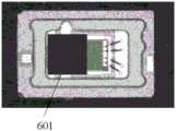
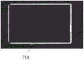
步骤S202,在标准合格工件图上手动选择两个大小不同的矩形区域,如图7和图8所示的701和801(红色区域),将选择的大小矩形区域作差得到胶水与溢胶区域,再将得到的区域与经过步骤201处理后的区域(扩张后的胶水区域)作差,得到溢胶区域;在本发明具体实施例中,所选择的大矩形区域需包含所有的溢胶区域,胶水区域,所选择的小矩形区域不能包含溢胶区域以及胶水区域,这样选取之后俩矩形相减之后得到的区域才能包含所有的溢胶区域以及胶水区域,该部分区域再减去胶水区域即得到溢胶区域。Step S202, manually select two rectangular areas of different sizes on the standard qualified workpiece map, such as 701 and 801 (red areas) as shown in Figures 7 and 8, and make a difference between the selected rectangular areas to obtain the glue and the overflow area. , and then make a difference between the obtained area and the area processed in step 201 (the expanded glue area) to obtain a glue overflow area; in the specific embodiment of the present invention, the selected large rectangular area needs to include all the glue overflow areas , glue area, the selected small rectangular area cannot include the overflow area and the glue area, so that the area obtained after the subtraction of the two rectangles can contain all the overflow area and the glue area, and the glue area is subtracted from this part of the area. Get the spill area.
步骤S3,利用所述标准合格工件图创建匹配模板。Step S3, using the standard qualified workpiece map to create a matching template.
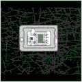
具体地,于模板图像(即标准合格工件图像)上选择一个矩形区域,得到匹配模板。要求该矩形区域在模板图像(即标准合格工件图图像)和待检测工件图像中均相同且与待检测的胶水区域和溢胶区域无关,得到匹配模板,如图6所示,601为选择的矩形区域(红色区域)。也就是说,本发明需要在所述标准合格工件图中选择该矩形区域做为模板,通过模板匹配则可以在待检测工件图中找到对应的区域Specifically, a rectangular area is selected on the template image (ie, the standard qualified workpiece image) to obtain a matching template. It is required that the rectangular area is the same in the template image (that is, the image of the standard qualified workpiece map) and the image of the workpiece to be detected, and has nothing to do with the glue area and the overflow area to be detected, so as to obtain a matching template, as shown in Figure 6, 601 is the selected Rectangular area (red area). That is to say, the present invention needs to select the rectangular area as a template in the standard qualified workpiece map, and through template matching, the corresponding area can be found in the to-be-detected workpiece map
在本发明中,于建立匹配模板后,则可利用ncc匹配算法可以自动得到在待检测工件中该模板的位置,再通过对选取的匹配模板与得到的在待检测工件中的模板位置的坐标和角度关系得到仿射变换矩阵,通过所述仿射变换矩阵则可以得到在待检测工件图中溢胶区域以及胶水区域,从而进行检测。在本发明中,匹配模板的作用就是为了得到标准图和待检测工件图之间的关系,再通过该关系以及标准图中所提取出的胶水与溢胶区域,即可得到待检测工件图中的胶水区域与溢胶区域,本发明中,不能直接用胶水区域与溢胶区域去匹配的原因是:在标准图和待检测图中该部分是不一样的,本发明的目的则是去判断是否不一致,以及到底是什么不一致。In the present invention, after the matching template is established, the ncc matching algorithm can be used to automatically obtain the position of the template in the workpiece to be detected, and then by comparing the selected matching template and the obtained coordinates of the template position in the workpiece to be detected The affine transformation matrix is obtained from the relationship with the angle, and through the affine transformation matrix, the glue overflow area and the glue area in the image of the workpiece to be detected can be obtained, so as to perform detection. In the present invention, the function of the matching template is to obtain the relationship between the standard map and the image of the workpiece to be inspected, and then through the relationship and the glue and the overflow area extracted from the standard image, the image of the workpiece to be inspected can be obtained. In the present invention, the reason why the glue area and the overflow area cannot be directly matched is: the part in the standard drawing and the drawing to be detected are different, and the purpose of the present invention is to judge Is it inconsistent, and what exactly is inconsistent.
步骤S4,获取待检测工件图像,将其与步骤S3所创建的匹配模板进行匹配。Step S4, acquire the image of the workpiece to be detected, and match it with the matching template created in step S3.
具体地,步骤S4进一步包括:Specifically, step S4 further includes:
步骤S400,获取所述待检测图片,利用与创建匹配模板所使用算子create_ncc_model相对应的模板匹配算子find_ncc_model进行模板匹配。在本发明具体实施例中,匹配方法可采用标准NCC算法,由于该方法为成熟技术,在此不赘述,这里需说明的是,create_ncc_model是用于创建模板的(将步骤S3区域即选取的矩形区域用作匹配的模板,应用到此处可以得到该模板的句柄)句柄,find_ncc_model是用来得到待检测工件图中的相对应的模板(可得到角度以及坐标),通过对选取的匹配模板与得到的在待检测工件中的模板位置的坐标和角度关系得到仿射变换矩阵,即通过vector_angle_to_rigid获得创建模板与匹配的点和角度(模板位置)之间的刚性仿射变换矩阵,最后通过该刚性仿射变换矩阵得到在待检测工件中的胶水区域以及溢胶区域用于检测,即利用该刚性仿射变换矩阵取得待检测工件初定位的胶水区域的位置信息。进一步地,使用reduce_domain算子取得所寻找到的区域,完成胶水区域的初定位,reduce_domain只是在得到需要的待检测图像中的胶水和溢胶区域后将图像的定义域缩小到要处理的区域(即胶水或溢胶区域),以便于后续处理;对经过步骤S109处理和步骤S202中大矩形得到的区域差应用任意二维转换,分别得到图9和图10,如图9示出了胶水区域901(红色区域),图10示出了溢胶区域101(红色区域);Step S400: Obtain the picture to be detected, and perform template matching using the template matching operator find_ncc_model corresponding to the operator create_ncc_model used to create the matching template. In the specific embodiment of the present invention, the standard NCC algorithm can be used for the matching method. Since this method is a mature technology, it will not be repeated here. It should be noted here that create_ncc_model is used to create a template (the rectangle selected in the area of step S3 The area is used as a matching template, and when applied here, the handle of the template can be obtained. find_ncc_model is used to obtain the corresponding template (angle and coordinates can be obtained) in the image of the workpiece to be detected. By comparing the selected matching template with The obtained coordinate and angle relationship of the template position in the workpiece to be detected obtains the affine transformation matrix, that is, the rigid affine transformation matrix between the created template and the matching point and angle (template position) is obtained through vector_angle_to_rigid, and finally through the rigid affine transformation matrix The affine transformation matrix obtains the glue area and the glue overflow area in the workpiece to be inspected for detection, that is, the rigid affine transformation matrix is used to obtain the position information of the glue area where the workpiece to be inspected is initially positioned. Further, use the reduce_domain operator to obtain the found area and complete the initial positioning of the glue area. reduce_domain just reduces the definition domain of the image to the area to be processed after obtaining the required glue and overflow area in the image to be detected ( That is, glue or glue overflow area), so as to facilitate subsequent processing; apply any two-dimensional transformation to the area difference obtained by the processing in step S109 and the large rectangle in step S202 to obtain Figure 9 and Figure 10 respectively, and Figure 9 shows the glue area 901 (red area), Figure 10 shows the overflow area 101 (red area);
步骤S401,将所述待检测工件图像定义域缩小到图10区域,再根据固定阈值进行全局阈分割,打开分割后的图像中具有圆形结构元素的区域;Step S401, reducing the definition domain of the workpiece image to be detected to the area in FIG. 10, then performing global threshold segmentation according to a fixed threshold, and opening the area with circular structural elements in the segmented image;
步骤S402,根据经过步骤S401处理后的区域的区域面积判断是否溢胶;Step S402, according to the area of the area processed in step S401, determine whether the glue overflows;
步骤S403,将所述待检测工件图像定义域缩小至图9区域,根据固定阈值进行全局阈分割,分别得到胶水反光区域和胶水不反光区域,返回这两个区域的联合;也就是说,在本发明中,利用步骤S401和s403缩减图像的定义域,将图像的定义域由全图改变到一个指定的区域,从而形成一幅新的图像。In step S403, the definition domain of the image of the workpiece to be detected is reduced to the area in FIG. 9, and global threshold segmentation is performed according to the fixed threshold to obtain the reflective area of the glue and the non-reflective area of the glue, and return the combination of these two areas; In the present invention, steps S401 and S403 are used to reduce the definition domain of the image, and the definition domain of the image is changed from the whole image to a designated area, thereby forming a new image.
步骤S404,用圆形结构元素关闭经步骤S403处理后的图像,对此区域进行孔洞填充再打开其中具有圆形结构元素的区域;In step S404, the image processed in step S403 is closed with a circular structure element, and the region is filled with holes, and then the region with the circular structure element is opened;
步骤S405,对经步骤S404处理后的图像进行连通域联合,根据形状—区域面积特征提取出面积在15000-9999999的区域(即灰度值总和在1500-99999之间的区域),计算提取出的区域的个数。In step S405, the image processed in step S404 is combined with connected domains, and an area with an area of 15000-9999999 (that is, an area with a sum of gray values between 1500 and 99999) is extracted according to the shape-area area feature, and calculated to extract the area. the number of regions.
步骤S5,根据步骤S4的匹配结果对点胶质量检测结果进行确定。In step S5, the dispensing quality detection result is determined according to the matching result in step S4.
步骤S501,根据步骤S405得到的个数进行判断,如果个数为0则表示无胶,个数大于1即断胶;In step S501, judgment is made according to the number obtained in step S405, if the number is 0, it means that there is no glue, and if the number is greater than 1, the glue is broken;
步骤S502,当个数等于1时,利用erosion_circle算子侵蚀步骤S305中提取出的区域图像中具有圆形结构元素的区域并计算个数,当个数大于1时则确定为少胶,否则为正常胶即合格品。需说明的是,所述erosion_circle算子为软件内置,其作用为用于检测当前区域图像并使得图像边界光滑,通过减少区域面积实现区域分割。Step S502, when the number is equal to 1, use the erosion_circle operator to erode the area with circular structural elements in the regional image extracted in step S305 and calculate the number, when the number is greater than 1, it is determined to be less glue, otherwise it is Normal glue is a qualified product. It should be noted that the erosion_circle operator is built-in in the software, and its function is to detect the current region image and smooth the image boundary, and realize region segmentation by reducing the region area.
综上所述,本发明一种点胶质量检测方法通过采集标准合格工件图图像,并基于HALCON图像分析处理技术确定边缘槽区域,然后根据步骤S1确定的区域创建匹配模板,获取待检测图片,将其与步骤S2所创建的匹配模板进行匹配,最后根据步骤S3的匹配结果对点胶质量检测结果进行确定,通过本发明,可提升点胶质量的检测效率,减少人工成本,尽可能保证产品质量。To sum up, a method for detecting glue dispensing quality of the present invention collects images of standard qualified workpiece images, determines the edge groove area based on the HALCON image analysis and processing technology, and then creates a matching template according to the area determined in step S1 to obtain the image to be detected, Match it with the matching template created in step S2, and finally determine the dispensing quality detection result according to the matching result in step S3. Through the present invention, the detection efficiency of dispensing quality can be improved, labor costs can be reduced, and products can be guaranteed as much as possible. quality.
上述实施例仅例示性说明本发明的原理及其功效,而非用于限制本发明。任何本领域技术人员均可在不违背本发明的精神及范畴下,对上述实施例进行修饰与改变。因此,本发明的权利保护范围,应如权利要求书所列。The above-mentioned embodiments merely illustrate the principles and effects of the present invention, but are not intended to limit the present invention. Any person skilled in the art can modify and change the above embodiments without departing from the spirit and scope of the present invention. Therefore, the protection scope of the present invention should be as listed in the claims.
Claims (10)
Priority Applications (1)
| Application Number | Priority Date | Filing Date | Title |
|---|---|---|---|
| CN202010191531.9ACN111462054B (en) | 2020-03-18 | 2020-03-18 | A kind of dispensing quality detection method |
Applications Claiming Priority (1)
| Application Number | Priority Date | Filing Date | Title |
|---|---|---|---|
| CN202010191531.9ACN111462054B (en) | 2020-03-18 | 2020-03-18 | A kind of dispensing quality detection method |
Publications (2)
| Publication Number | Publication Date |
|---|---|
| CN111462054Atrue CN111462054A (en) | 2020-07-28 |
| CN111462054B CN111462054B (en) | 2023-04-07 |
Family
ID=71685605
Family Applications (1)
| Application Number | Title | Priority Date | Filing Date |
|---|---|---|---|
| CN202010191531.9AActiveCN111462054B (en) | 2020-03-18 | 2020-03-18 | A kind of dispensing quality detection method |
Country Status (1)
| Country | Link |
|---|---|
| CN (1) | CN111462054B (en) |
Cited By (13)
| Publication number | Priority date | Publication date | Assignee | Title |
|---|---|---|---|---|
| CN112164032A (en)* | 2020-09-14 | 2021-01-01 | 浙江华睿科技有限公司 | Dispensing method, dispensing device, electronic equipment and storage medium |
| CN112288732A (en)* | 2020-11-05 | 2021-01-29 | 昆山丘钛光电科技有限公司 | A detection method, device, equipment and system for dispensing glue |
| CN112365446A (en)* | 2020-10-19 | 2021-02-12 | 杭州亿奥光电有限公司 | Paper bag bonding quality detection method |
| CN113252697A (en)* | 2021-06-18 | 2021-08-13 | 深圳远荣智能制造股份有限公司 | Material quality detection method and equipment and computer readable storage medium |
| CN113284113A (en)* | 2021-05-27 | 2021-08-20 | 西安闻泰信息技术有限公司 | Glue overflow flaw detection method and device, computer equipment and readable storage medium |
| CN114049035A (en)* | 2021-11-24 | 2022-02-15 | 深圳市领志光机电自动化系统有限公司 | Automatic dispensing monitoring system and method based on Internet |
| CN114581445A (en)* | 2022-05-06 | 2022-06-03 | 深圳市元硕自动化科技有限公司 | Sectional detection method, system and equipment for dispensing products and storage medium |
| CN114742827A (en)* | 2022-06-09 | 2022-07-12 | 深圳市腾盛精密装备股份有限公司 | Glue detection method, device, equipment and medium based on flying shooting of visual sensor |
| CN115619779A (en)* | 2022-12-14 | 2023-01-17 | 杭州百子尖科技股份有限公司 | Hot melt adhesive box sealing machine vision detection system and method based on thermal imaging |
| CN116630333A (en)* | 2023-07-26 | 2023-08-22 | 常州铭赛机器人科技股份有限公司 | Method for on-line monitoring dispensing quality of laser radar optical lens |
| CN118009889A (en)* | 2024-04-09 | 2024-05-10 | 常州铭赛机器人科技股份有限公司 | Method for measuring position of workpiece dispensing slot |
| CN119395032A (en)* | 2024-12-27 | 2025-02-07 | 包头市英思特稀磁新材料股份有限公司 | A magnet dispensing detection method |
| CN119850627A (en)* | 2025-03-20 | 2025-04-18 | 深圳荣耀智能机器有限公司 | Dispensing detection method, dispensing detection system and electronic equipment |
Citations (2)
| Publication number | Priority date | Publication date | Assignee | Title |
|---|---|---|---|---|
| CN108896577A (en)* | 2018-05-30 | 2018-11-27 | 昆山睿力得软件技术有限公司 | A kind of automatic testing method of brake block profile defects |
| CN110555829A (en)* | 2019-08-12 | 2019-12-10 | 华南理工大学 | method for detecting chip dispensing condition |
- 2020
- 2020-03-18CNCN202010191531.9Apatent/CN111462054B/enactiveActive
Patent Citations (2)
| Publication number | Priority date | Publication date | Assignee | Title |
|---|---|---|---|---|
| CN108896577A (en)* | 2018-05-30 | 2018-11-27 | 昆山睿力得软件技术有限公司 | A kind of automatic testing method of brake block profile defects |
| CN110555829A (en)* | 2019-08-12 | 2019-12-10 | 华南理工大学 | method for detecting chip dispensing condition |
Cited By (18)
| Publication number | Priority date | Publication date | Assignee | Title |
|---|---|---|---|---|
| CN112164032B (en)* | 2020-09-14 | 2023-12-29 | 浙江华睿科技股份有限公司 | Dispensing method and device, electronic equipment and storage medium |
| CN112164032A (en)* | 2020-09-14 | 2021-01-01 | 浙江华睿科技有限公司 | Dispensing method, dispensing device, electronic equipment and storage medium |
| CN112365446A (en)* | 2020-10-19 | 2021-02-12 | 杭州亿奥光电有限公司 | Paper bag bonding quality detection method |
| CN112288732A (en)* | 2020-11-05 | 2021-01-29 | 昆山丘钛光电科技有限公司 | A detection method, device, equipment and system for dispensing glue |
| CN113284113A (en)* | 2021-05-27 | 2021-08-20 | 西安闻泰信息技术有限公司 | Glue overflow flaw detection method and device, computer equipment and readable storage medium |
| CN113252697A (en)* | 2021-06-18 | 2021-08-13 | 深圳远荣智能制造股份有限公司 | Material quality detection method and equipment and computer readable storage medium |
| CN113252697B (en)* | 2021-06-18 | 2021-10-08 | 深圳远荣智能制造股份有限公司 | Material quality detection method and equipment and computer readable storage medium |
| CN114049035A (en)* | 2021-11-24 | 2022-02-15 | 深圳市领志光机电自动化系统有限公司 | Automatic dispensing monitoring system and method based on Internet |
| CN114581445A (en)* | 2022-05-06 | 2022-06-03 | 深圳市元硕自动化科技有限公司 | Sectional detection method, system and equipment for dispensing products and storage medium |
| CN114742827A (en)* | 2022-06-09 | 2022-07-12 | 深圳市腾盛精密装备股份有限公司 | Glue detection method, device, equipment and medium based on flying shooting of visual sensor |
| CN114742827B (en)* | 2022-06-09 | 2022-09-20 | 深圳市腾盛精密装备股份有限公司 | Glue detection method, device, equipment and medium based on flying shooting of visual sensor |
| CN115619779A (en)* | 2022-12-14 | 2023-01-17 | 杭州百子尖科技股份有限公司 | Hot melt adhesive box sealing machine vision detection system and method based on thermal imaging |
| CN115619779B (en)* | 2022-12-14 | 2023-03-17 | 杭州百子尖科技股份有限公司 | Hot melt adhesive box sealing machine vision detection system and method based on thermal imaging |
| CN116630333A (en)* | 2023-07-26 | 2023-08-22 | 常州铭赛机器人科技股份有限公司 | Method for on-line monitoring dispensing quality of laser radar optical lens |
| CN116630333B (en)* | 2023-07-26 | 2023-09-29 | 常州铭赛机器人科技股份有限公司 | Method for on-line monitoring dispensing quality of laser radar optical lens |
| CN118009889A (en)* | 2024-04-09 | 2024-05-10 | 常州铭赛机器人科技股份有限公司 | Method for measuring position of workpiece dispensing slot |
| CN119395032A (en)* | 2024-12-27 | 2025-02-07 | 包头市英思特稀磁新材料股份有限公司 | A magnet dispensing detection method |
| CN119850627A (en)* | 2025-03-20 | 2025-04-18 | 深圳荣耀智能机器有限公司 | Dispensing detection method, dispensing detection system and electronic equipment |
Also Published As
| Publication number | Publication date |
|---|---|
| CN111462054B (en) | 2023-04-07 |
Similar Documents
| Publication | Publication Date | Title |
|---|---|---|
| CN111462054B (en) | A kind of dispensing quality detection method | |
| CN110555829B (en) | A detection method for chip dispensing | |
| CN109580630B (en) | Visual inspection method for defects of mechanical parts | |
| CN114550021B (en) | Surface defect detection method and device based on feature fusion | |
| Loverdos et al. | An innovative image processing-based framework for the numerical modelling of cracked masonry structures | |
| WO2019134252A1 (en) | Method and device for automated portrayal and accurate measurement of width of structural crack | |
| CN114693633B (en) | Welding defect detection method, device and detection system | |
| CN110097547B (en) | Automatic detection method for welding seam negative film counterfeiting based on deep learning | |
| CN113706464B (en) | Printed matter appearance quality detection method and system | |
| CN112734761B (en) | Industrial product image boundary contour extraction method | |
| CN116630323B (en) | An automatic calculation method, system, medium and equipment for dense metal corrosion depth | |
| CN103839271B (en) | A kind of image texture synthetic method based on optimal coupling | |
| CN111986170A (en) | Defect detection algorithm based on Mask R-CNN (deep neural network) | |
| CN109583377B (en) | Control method and device for pipeline model reconstruction and upper computer | |
| CN117260055A (en) | Weld quality detection method and computer equipment for thick-wall welded workpiece | |
| CN110222704A (en) | A kind of Weakly supervised object detection method and device | |
| CN101685000B (en) | Computer system and method for image boundary scan | |
| CN119338897B (en) | Insulation board adhesive area ratio detection method, device, terminal and storage medium | |
| CN120102589A (en) | Surface defect detection method and related equipment for touch screen | |
| CN115526854A (en) | A mirror surface defect detection method, device and medium based on binary fringes | |
| CN118918285A (en) | Monocular vision-based concrete structure surface defect detection and positioning three-dimensional reconstruction method | |
| CN110426395A (en) | A kind of solar energy EL cell silicon chip surface inspecting method and device | |
| CN110555385A (en) | welding seam characteristic point solving method based on variable step length curvature filtering | |
| CN117541565A (en) | Detection method, detection device and storage medium | |
| JP7562851B2 (en) | Method for analyzing a component, method for training a system, device, computer program and computer readable storage medium |
Legal Events
| Date | Code | Title | Description |
|---|---|---|---|
| PB01 | Publication | ||
| PB01 | Publication | ||
| SE01 | Entry into force of request for substantive examination | ||
| SE01 | Entry into force of request for substantive examination | ||
| GR01 | Patent grant | ||
| GR01 | Patent grant | ||
| TR01 | Transfer of patent right | Effective date of registration:20250113 Address after:Room 102, No. 7 Tengfei 1st Street, Huangpu District, Guangzhou City, Guangdong Province 510000 Patentee after:Guangdong Weihua Intelligent Technology Co.,Ltd. Country or region after:China Address before:No. 230, Waihuan West Road, Guangzhou University Town, Panyu, Guangzhou City, Guangdong Province, 510006 Patentee before:Guangzhou University Country or region before:China | |
| TR01 | Transfer of patent right |