CN111456986A - A memory alloy locking and releasing mechanism - Google Patents
A memory alloy locking and releasing mechanismDownload PDFInfo
- Publication number
- CN111456986A CN111456986ACN202010203211.0ACN202010203211ACN111456986ACN 111456986 ACN111456986 ACN 111456986ACN 202010203211 ACN202010203211 ACN 202010203211ACN 111456986 ACN111456986 ACN 111456986A
- Authority
- CN
- China
- Prior art keywords
- locking
- memory alloy
- spring
- cap
- separation
- Prior art date
- Legal status (The legal status is an assumption and is not a legal conclusion. Google has not performed a legal analysis and makes no representation as to the accuracy of the status listed.)
- Granted
Links
- 229910001285shape-memory alloyInorganic materials0.000titleclaimsabstractdescription60
- 230000007246mechanismEffects0.000titleclaimsabstractdescription43
- 238000000926separation methodMethods0.000claimsdescription84
- 230000006835compressionEffects0.000claimsdescription22
- 238000007906compressionMethods0.000claimsdescription22
- 230000001050lubricating effectEffects0.000claimsdescription7
- 239000007787solidSubstances0.000claimsdescription7
- 239000010935stainless steelSubstances0.000claimsdescription6
- 229910001220stainless steelInorganic materials0.000claimsdescription6
- 229910000838Al alloyInorganic materials0.000claimsdescription4
- 239000000463materialSubstances0.000claimsdescription4
- 230000013011matingEffects0.000claimsdescription4
- 238000006073displacement reactionMethods0.000claimsdescription3
- 238000009434installationMethods0.000claimsdescription3
- 238000000034methodMethods0.000abstractdescription4
- 230000007547defectEffects0.000abstractdescription3
- 230000008569processEffects0.000abstractdescription3
- 239000000779smokeSubstances0.000abstractdescription2
- 239000000956alloySubstances0.000description4
- 238000010586diagramMethods0.000description4
- 230000006870functionEffects0.000description4
- 238000004200deflagrationMethods0.000description3
- 230000009471actionEffects0.000description2
- 230000009286beneficial effectEffects0.000description2
- 230000008859changeEffects0.000description2
- 238000005474detonationMethods0.000description2
- 230000001133accelerationEffects0.000description1
- 229910045601alloyInorganic materials0.000description1
- 230000004323axial lengthEffects0.000description1
- 230000003749cleanlinessEffects0.000description1
- 230000007812deficiencyEffects0.000description1
- 230000007613environmental effectEffects0.000description1
- 230000005284excitationEffects0.000description1
- 239000000446fuelSubstances0.000description1
- 230000005484gravityEffects0.000description1
- 230000006386memory functionEffects0.000description1
- 229910052751metalInorganic materials0.000description1
- 230000003068static effectEffects0.000description1
Images


Classifications
- F—MECHANICAL ENGINEERING; LIGHTING; HEATING; WEAPONS; BLASTING
- F16—ENGINEERING ELEMENTS AND UNITS; GENERAL MEASURES FOR PRODUCING AND MAINTAINING EFFECTIVE FUNCTIONING OF MACHINES OR INSTALLATIONS; THERMAL INSULATION IN GENERAL
- F16B—DEVICES FOR FASTENING OR SECURING CONSTRUCTIONAL ELEMENTS OR MACHINE PARTS TOGETHER, e.g. NAILS, BOLTS, CIRCLIPS, CLAMPS, CLIPS OR WEDGES; JOINTS OR JOINTING
- F16B1/00—Devices for securing together, or preventing relative movement between, constructional elements or machine parts
- F16B1/02—Means for securing elements of mechanisms after operation
- F16B1/04—Means for securing elements of mechanisms after operation disengaged by movement of the actuating member of the element
- F—MECHANICAL ENGINEERING; LIGHTING; HEATING; WEAPONS; BLASTING
- F16—ENGINEERING ELEMENTS AND UNITS; GENERAL MEASURES FOR PRODUCING AND MAINTAINING EFFECTIVE FUNCTIONING OF MACHINES OR INSTALLATIONS; THERMAL INSULATION IN GENERAL
- F16B—DEVICES FOR FASTENING OR SECURING CONSTRUCTIONAL ELEMENTS OR MACHINE PARTS TOGETHER, e.g. NAILS, BOLTS, CIRCLIPS, CLAMPS, CLIPS OR WEDGES; JOINTS OR JOINTING
- F16B2200/00—Constructional details of connections not covered for in other groups of this subclass
- F16B2200/77—Use of a shape-memory material
Landscapes
- Engineering & Computer Science (AREA)
- General Engineering & Computer Science (AREA)
- Mechanical Engineering (AREA)
- Refuge Islands, Traffic Blockers, Or Guard Fence (AREA)
- Filling Or Discharging Of Gas Storage Vessels (AREA)
Abstract
Translated fromChinese
Description
Translated fromChinese技术领域technical field
本发明涉及一种采用记忆合金驱动的机构,属于锁紧、释放技术领域。The invention relates to a mechanism driven by a memory alloy, belonging to the technical field of locking and releasing.
背景技术Background technique
锁紧、释放通常是对至少有1个运动自由度的机构进行的固定和释放操作,锁紧的目的是约束固定被锁紧机构的活动部件,避免发生碰撞或在外界激励下被锁紧机构发生共振现象。释放的目的是释放被锁紧机构的活动部件,使被锁紧机构获得被锁紧前原有的自由度数量。Locking and releasing are usually the fixing and releasing operations for a mechanism with at least one degree of freedom of movement. The purpose of locking is to restrain and fix the moving parts of the locked mechanism and avoid collision or the locked mechanism under external excitation. resonance occurs. The purpose of releasing is to release the movable parts of the locked mechanism, so that the locked mechanism can obtain the original number of degrees of freedom before being locked.
近年来,国内外常见的锁紧、释放装置均采用火工品锁紧、释放装置,其锁紧原理为利用螺栓、螺母压紧以及压紧面两侧凹凸配合的原理约束被锁紧机构的自由度,释放原理为利用火工品装置内部的燃料瞬间爆燃产生的的冲击力,切断压紧螺栓,最终实现恢复被锁紧机构自由度的目的。In recent years, the common locking and releasing devices at home and abroad all use pyrotechnic locking and releasing devices. The degree of freedom, the release principle is to use the impact force generated by the instantaneous deflagration of the fuel inside the pyrotechnic device to cut off the compression bolt, and finally achieve the purpose of restoring the degree of freedom of the locked mechanism.
现有技术中,传统的火工品锁紧、释放装置主要存在如下问题:In the prior art, the traditional pyrotechnic locking and releasing devices mainly have the following problems:
第一、火工品锁紧、释放装置的解锁瞬间,爆燃产生的冲击力达到百倍于重力加速度,存在解锁冲击大的缺陷。First, at the moment of unlocking the pyrotechnic product locking and releasing device, the impact force generated by the deflagration reaches a hundred times the acceleration of gravity, and there is a defect that the unlocking impact is large.
第二、每套火工品锁紧、释放装置仅能实现一次爆燃释放功能,当存在多次释放需求时,需要不断更换新的火工品锁紧、释放装置,使用成本较高。Second, each set of pyrotechnic locking and releasing device can only realize the function of deflagration release once. When there is a need for multiple releases, new pyrotechnic locking and releasing devices need to be continuously replaced, and the use cost is high.
第三、火工品锁紧、释放装置解锁释放后,被锁紧机构在锁机位置大多不具有沿与压紧面平行的切向运动的自由度,使被锁紧机构在锁紧位置运动范围受限。Third, after the pyrotechnic product is locked and the release device is unlocked and released, the locked mechanism in the locking position mostly does not have the freedom of tangential movement parallel to the pressing surface, so that the locked mechanism moves in the locked position Scope is limited.
第四、具备一次性起爆释放功能的火工品锁紧、释放装置因不同批次零件加工误差、安装误差、材料批次差异等因素影响,存在锁紧或释放状态一致性差等不足之处。Fourth, the pyrotechnic product locking and releasing device with the function of one-time detonation and release has shortcomings such as poor consistency of locking or releasing state due to the influence of different batches of parts processing error, installation error, material batch difference and other factors.
发明内容SUMMARY OF THE INVENTION
本发明解决的技术问题是:克服现有技术的不足,本发明提供了一种记忆合金锁紧释放机构,通过一定次数内可重复使用的记忆合金解锁器、锁紧座、压紧锥、分离垫、锁紧臂、锁紧杆的配合,实现了一定次数内可重复锁紧解锁、解锁冲击小、锁紧位置解锁后不影响运动件沿压紧面切向运动、重复锁紧一致性良好的功能,弥补了传统锁紧、解锁装置的缺陷。The technical problem solved by the present invention is: to overcome the deficiencies of the prior art, the present invention provides a memory alloy locking and releasing mechanism, which can be reused within a certain number of times through a memory alloy unlocker, a locking seat, a pressing cone, a separation The cooperation of the pad, the locking arm and the locking rod realizes the repeated locking and unlocking within a certain number of times, the unlocking impact is small, the tangential movement of the moving part along the pressing surface is not affected after the locking position is unlocked, and the repeated locking consistency is good It makes up for the defects of traditional locking and unlocking devices.
本发明的技术解决方案是:一种记忆合金锁紧释放机构,包括锁紧座、压紧锥、记忆合金解锁器、分离帽、锁紧杆、锁紧臂、锁紧螺母、锁防脱螺母、防脱帽、防脱弹簧、分离垫、分离弹簧、拉簧、收纳罩;The technical solution of the present invention is: a memory alloy locking and releasing mechanism, comprising a locking seat, a pressing cone, a memory alloy unlocking device, a separating cap, a locking rod, a locking arm, a locking nut, and a locking anti-dropping nut , Anti-off cap, anti-off spring, separation pad, separation spring, tension spring, storage cover;
锁紧座为两端设有通孔的壳体;压紧锥安装在锁紧座内,从锁紧座一端端口伸出,压紧锥一端安装固定记忆合金解锁器,另一端为凸锥面用于和锁紧臂端口内壁的凹锥面贴合;分离弹簧一端和锁紧座上用于安装压紧锥的轴肩压接,另一端和压紧锥外壁上设置的台阶压接;记忆合金解锁器上与分离帽连接的配合端头插入压紧锥内孔中,端头在记忆合金解锁器处于锁紧状态时和分离帽固连,端头在记忆合金解锁器处于解锁释放状态时和记忆合金解锁器分离;锁紧臂一端安装防脱帽,另一端与分离垫贴合;分离垫位于锁紧座安装有压紧锥的一端,安装在锁紧臂和锁紧座之间;拉簧一端和分离垫挂接,拉簧另一端与锁紧座另一端挂接;锁紧杆一端伸入锁紧臂的内腔与分离帽连接,另一端从锁紧臂端口伸出并安装锁紧螺母,锁紧杆从防脱帽伸出的一端安装锁防脱螺母;防脱弹簧安装在防脱帽内部;收纳罩安装于锁紧座、拉簧的外侧,用于在解锁后收纳分离垫和拉簧。The locking seat is a shell with through holes at both ends; the pressing cone is installed in the locking seat and protrudes from one end of the locking seat, one end of the pressing cone is installed with a fixed memory alloy unlocker, and the other end is a convex cone surface It is used to fit with the concave cone surface of the inner wall of the locking arm port; one end of the separation spring is crimped with the shoulder on the locking seat for installing the compression cone, and the other end is crimped with the step set on the outer wall of the compression cone; memory The mating end of the alloy unlocker connected with the separation cap is inserted into the inner hole of the compression cone, the end is fixed with the separation cap when the memory alloy unlocker is in the locked state, and the end is in the unlocked and released state of the memory alloy unlocker. It is separated from the memory alloy unlocker; one end of the locking arm is installed with an anti-off cap, and the other end is attached to the separation pad; the separation pad is located at the end of the locking seat where the compression cone is installed, and is installed between the locking arm and the locking seat; pull One end of the spring is connected to the separation pad, and the other end of the tension spring is connected to the other end of the locking seat; Tighten the nut, the end of the locking rod protruding from the anti-falling cap is installed with a locking and anti-falling nut; the anti-falling spring is installed inside the anti-falling cap; the storage cover is installed on the outside of the locking seat and the tension spring, which is used to store the separation pad and tension spring.
所述压紧锥为空心多阶梯轴,一端为平面用于安装固定记忆合金解锁器,另一端为凸锥面用于和锁紧臂凹锥面贴合,压紧锥外壁上设置用于和锁紧座间隙配合的台阶和用于安装并限制分离弹簧位移的台阶。The pressing cone is a hollow multi-step shaft, one end is a flat surface for installing and fixing the memory alloy unlocker, the other end is a convex cone surface for fitting with the concave cone surface of the locking arm, and the outer wall of the pressing cone is provided for and A step for the clearance fit of the lock seat and a step for mounting and limiting the displacement of the release spring.
所述压紧锥采用不锈钢材料,外表面镀有固体润滑膜。The pressing cone is made of stainless steel, and the outer surface is plated with a solid lubricating film.
所述分离垫采用不锈钢材料,表面镀有固体润滑膜。The separation pad is made of stainless steel, and the surface is plated with a solid lubricating film.
所述收纳罩内设置有能容纳分离垫和拉簧的局部区域封闭空间;收纳罩边沿采用卷边处理。The storage cover is provided with a partial area closed space capable of accommodating the separation pad and the tension spring; the edge of the storage cover is processed by curling.
所述锁紧座、锁紧臂的材料采用铝合金。The material of the locking seat and the locking arm is aluminum alloy.
分离弹簧在机构锁紧状态时为压缩状态;分离弹簧为直螺旋压簧。The separation spring is in a compressed state when the mechanism is locked; the separation spring is a straight helical compression spring.
防脱弹簧在机构锁紧状态时为压缩状态;防脱弹簧为直线螺旋压簧。The anti-drop spring is in a compressed state when the mechanism is locked; the anti-drop spring is a linear helical compression spring.
所述拉簧在机构锁紧状态为拉伸状态,拉簧为直线螺旋拉簧。The tension spring is in a tension state when the mechanism is locked, and the tension spring is a linear helical tension spring.
分离帽与记忆合金解锁器释放分离后,锁紧螺母、防脱帽、防脱螺母在防脱弹簧的推动下沿锁紧臂轴向移动,带动锁紧杆和分离帽,直至分离帽接触到锁紧臂内腔壁面位置停止移动;记忆合金解锁器和压紧锥被分离弹簧推动并落入锁紧座内腔,分离垫被拉簧拉出落入收纳罩。After the release cap and the memory alloy unlocker are released and separated, the lock nut, anti-drop cap, and anti-drop nut move axially along the locking arm under the push of the anti-drop spring, driving the locking rod and the separation cap until the separation cap touches the lock. The position of the inner cavity wall of the tightening arm stops moving; the memory alloy unlocker and the compression cone are pushed by the separation spring and fall into the inner cavity of the locking seat, and the separation pad is pulled out by the tension spring and falls into the storage cover.
本发明与现有技术相比的有益效果是:The beneficial effects of the present invention compared with the prior art are:
(1)本发明通过采用记忆合金解锁器,实现了对具有一定运动自由度机构的锁紧、释放功能。与使用传统火工品相比降低了解锁过程的冲击力,有利于保护被锁紧机构及载荷;因记忆合金解锁器解锁过程无烟雾等多余物产生,满足某些应用场合对环境洁净度的要求。(1) The present invention realizes the locking and releasing functions of a mechanism with a certain degree of freedom of movement by using a memory alloy unlocker. Compared with the use of traditional pyrotechnics, the impact force of the unlocking process is reduced, which is beneficial to protect the locked mechanism and load; because the memory alloy unlocker does not generate smoke and other excesses during the unlocking process, it meets the requirements of environmental cleanliness in some applications. Require.
(2)本发明通过采用具有一定可重复锁紧、释放次数的记忆合金解锁器,实现了对具有一定运动自由度机构的可重复锁紧、释放功能。与使用传统一次性起爆动作的火工品解锁器相比,降低了试验的成本。同时,减少了因更换解锁器硬件引入的零件批次性尺寸误差、装调误差、材料批次差异性。(2) The present invention realizes the repeatable locking and releasing functions of a mechanism with a certain degree of freedom of movement by using a memory alloy unlocker with certain repeatable locking and releasing times. Compared with pyrotechnic unlockers using traditional one-time detonation action, the cost of experimentation is reduced. At the same time, the batch size error of parts, assembly and adjustment errors, and material batch differences introduced by replacing the unlocker hardware are reduced.
(3)本发明通过采用分离弹簧,将解锁释放后的记忆合金解锁器、压紧锥螺接组合件与运动件锁紧臂完全分离,使锁紧臂在锁紧位置不仅具有沿压紧平面法向向外的自由度,还具有沿压紧平面切向平移的自由度。(3) The present invention completely separates the unlocked and released memory alloy unlocker, the compression cone screwing assembly and the moving part locking arm by using a separation spring, so that the locking arm not only has a movement along the pressing plane at the locking position The degrees of freedom are normal outward, and also have degrees of freedom for tangential translation along the compression plane.
(4)本发明通过采用分离垫、拉簧、收纳罩组合方式,当机构解锁释放后,分离垫被拉簧拉入收纳罩,分离垫的厚度即运动件锁紧臂和静止件锁紧座之间的静动间隙,通过调整分离垫的厚度,可以调整被锁紧机构的静动间隙。(4) The present invention adopts the combination of the separation pad, the tension spring and the storage cover. When the mechanism is unlocked and released, the separation pad is pulled into the storage cover by the tension spring, and the thickness of the separation pad is the locking arm of the moving part and the locking seat of the stationary part. By adjusting the thickness of the separation pad, the static and dynamic gap of the locked mechanism can be adjusted.
(5)本发明整体结构紧凑,适用于多种工作环境,使用寿命相对较长,在复杂工况下依然能够良好工作,具有适用范围广的特点,具备良好的空间应用前景。(5) The present invention has a compact overall structure, is suitable for various working environments, has a relatively long service life, can still work well under complex working conditions, has the characteristics of wide application range, and has a good space application prospect.
附图说明Description of drawings
附图用来提供对本发明的进一步理解,构成本申请的一部分,本发明的实施例及其说明用于解释本发明,并不构成对本发明的不当限定。在附图中:The accompanying drawings are used to provide a further understanding of the present invention and constitute a part of the present application. The embodiments of the present invention and their descriptions are used to explain the present invention and do not constitute an improper limitation of the present invention. In the attached image:
图1为本发明锁紧状态的结构图;Fig. 1 is the structure diagram of the locked state of the present invention;
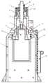
图2为本发明锁紧状态的剖视图;Fig. 2 is the sectional view of the locked state of the present invention;
图3为本发明解锁释放状态的结构图;Fig. 3 is the structure diagram of unlocking and releasing state of the present invention;
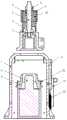
图4为本发明解锁释放状态的剖视图;Fig. 4 is the sectional view of the unlocking release state of the present invention;
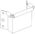
图5为压紧锥、记忆合金解锁器螺接结构图;Fig. 5 is the screw connection structure diagram of the compression cone and the memory alloy unlocker;
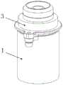
图6为收纳罩的结构图。FIG. 6 is a structural diagram of a storage cover.
其中:1锁紧座;2压紧锥;3记忆合金解锁器;4分离帽;5锁紧杆;6锁紧臂;7锁紧螺母;8防脱螺母;9防脱帽;10防脱弹簧;11分离垫;12分离弹簧;13拉簧;14收纳罩Among them: 1 locking seat; 2 pressing cone; 3 memory alloy unlocker; 4 separating cap; 5 locking rod; 6 locking arm; 7 locking nut; ; 11 separation pad; 12 separation spring; 13 tension spring; 14 storage cover
具体实施方式Detailed ways
为使本发明的方案更加明了,下面结合附图说明和具体实施例对本发明作进一步描述:In order to make the solution of the present invention clearer, the present invention will be further described below in conjunction with the accompanying drawings and specific embodiments:
如图1~6所示,一种记忆合金锁紧释放机构,包括锁紧座1、压紧锥2、记忆合金解锁器3、分离帽4、锁紧杆5、锁紧臂6、锁紧螺母7、防脱螺母8、防脱帽9、防脱弹簧10、分离垫11、分离弹簧12、拉簧13、收纳罩14。As shown in Figures 1-6, a memory alloy locking and releasing mechanism includes a
锁紧座1为两端设有通孔的壳体,壳体一端设有用于穿设压紧锥2、记忆合金解锁器3、分离弹簧12的通孔,还设有用于安装固定的法兰,壳体另一端有用于穿设和安装压紧锥的轴肩,壳体外表面有用于安装收纳罩14的螺孔,壳体外表面还有螺纹孔用于安装螺钉并固定拉簧13,锁紧座1安装压紧锥的一端外端面为平面用于和分离垫11平面贴合;压紧锥2为空心多阶梯轴,轴的一端为平面用于安装固定记忆合金解锁器3,轴另一端为凸锥面用于和锁紧臂6凹锥面贴合并承受锁紧力,压紧锥2有用于和锁紧座1间隙配合的台阶,有用于安装并限制分离弹簧12位移的台阶;分离弹簧12为直螺旋压簧,一端和锁紧座1穿设压紧锥2的轴肩压接,另一端和压紧锥2的台阶压接;记忆合金解锁器3有用于和分离帽4连接的配合端头,端头在记忆合金解锁器3锁紧状态和分离帽4完全固连,端头在解锁释放状态和记忆合金解锁器3完全分离;The
分离垫11上表面和锁紧臂6贴合,下表面和锁紧座1贴合,中心孔穿设压紧锥2且与压紧锥2间隙配合,分离垫11所有表面镀固体润滑膜处理,分离垫11设有小孔用于悬臂拉簧;拉簧13为直线螺旋拉簧且两端设有挂钩,一端挂钩用于和分离垫11挂接,另一端挂钩用于和锁紧座1上安装的螺钉挂接;锁紧臂6设有用于压紧分离垫11的平面,还设有用于穿设和容纳分离帽4和锁紧杆5的腔体,腔体深度大于分离帽4的轴向长度且分离帽4进入腔体后分离帽4的端面不高出锁紧臂6压紧平面,锁紧臂6上设有用于穿设锁紧杆5的通孔和用于安装防脱帽9、防脱弹簧10的轴肩,设有用于和锁紧螺母7贴合的平面,还设有用于连接被锁紧机构或零件的连接法兰;锁紧杆5为杆状结构,杆一端设有螺纹用于和分离帽4螺接,另一端设有螺纹用于和锁紧螺母7、防脱螺母8螺接;防脱弹簧10为直线螺旋压簧,压簧套于锁紧臂6的台阶轴外同时套于防脱帽9的壳体内,防脱弹簧10一个端面和防脱帽9的内腔臂贴合,另一个端面和锁紧臂6的轴肩贴合,防脱弹簧10的原长减去其锁紧状态的长度之差大于分离帽4缩入锁紧臂6的长度;防脱帽9为薄壳结构,壳体一端设有用于穿设锁紧杆5的通孔并在壳体外端面和防脱螺母贴合,壳体另一端用于放入防脱弹簧10并在壳体端面和锁紧臂6的轴肩贴合;收纳罩14安装于锁紧座1、拉簧13的外侧,收纳罩14边沿有卷边用于防止其和拉簧13钩挂,收纳罩14局部封闭容纳分离垫和拉簧且不和锁紧臂有运动干涉。The upper surface of the
压紧锥2安装在锁紧座1内,从锁紧座1一端端口伸出,压紧锥2一端安装固定记忆合金解锁器3,另一端为凸锥面用于和锁紧臂6端口内壁的凹锥面贴合;分离弹簧12一端和锁紧座1上用于安装压紧锥2的轴肩压接,另一端和压紧锥2外壁上设置的台阶压接;记忆合金解锁器3上与分离帽4连接的配合端头插入压紧锥2内孔中,端头在记忆合金解锁器3处于锁紧状态时和分离帽4固连,端头在记忆合金解锁器3处于解锁释放状态时和记忆合金解锁器3分离;锁紧臂6一端安装防脱帽9,另一端与分离垫11贴合;分离垫11位于锁紧座1安装有压紧锥2的一端,安装在锁紧臂6和锁紧座1之间;拉簧13一端和分离垫11挂接,拉簧13另一端与锁紧座1另一端挂接;锁紧杆5一端伸入锁紧臂6的内腔与分离帽4连接,另一端从锁紧臂6端口伸出并安装锁紧螺母7,锁紧杆5从防脱帽9伸出的一端安装锁防脱螺母8;防脱弹簧10安装在防脱帽9内部;收纳罩14安装于锁紧座1、拉簧13的外侧,用于在解锁后收纳分离垫11和拉簧13。The
分离弹簧12和防脱弹簧10在机构锁紧状态皆为压缩状态。分离弹簧12的原长减去机构锁紧状态时其的长度大于压紧锥2超出锁紧座1的高度。防脱弹簧10的原长大于机构解锁释放后分离帽4在锁紧臂6内的运动长度。Both the
拉簧13在机构锁紧状态为拉伸状态,当机构解锁释放后拉簧13收缩拉动分离垫11,最终和分离垫11一起收缩入收纳盒内局部封闭空间,且分离垫11和压紧锥2、锁紧臂6不发生运动干涉。The
记忆合金解锁器3解锁动力源采用记忆合金原理驱动,由主要成分为有形状记忆功能的金属元素制作而成的丝状或片状记忆合金材料,在其温度达到一定值时记忆合金材料自身尺寸会发生改变,利用这种尺寸的改变可以驱动与记忆合金材料连接的物体的运动。
锁紧座1和压紧锥11间隙配合,锁紧座1采用铝合金材料。The locking
压紧锥2外表面镀固体润滑膜,压紧锥2采用不锈钢材料。The outer surface of the
分离垫11全部表面镀固体润滑膜,分离垫11采用不锈钢材料。The entire surface of the
分离帽4解锁后全部缩入锁紧臂6且不超出锁紧臂6的压紧端面。After the
收纳罩14边沿采用卷边处理用于避免和拉簧13钩挂。收纳罩14有局部封闭空间用于容纳分离垫11和拉簧13。收纳罩14采用铝合金。The edge of the
本发明的工作原理是:The working principle of the present invention is:
机构锁紧状态的锁紧力从锁紧螺母7依次传递至锁紧杆5、分离帽4、记忆合金解锁器3、压紧锥2、锁紧座1、分离垫11、锁紧臂6又传递回锁紧螺母7,当记忆合金解锁器3动作机构解锁释放后,锁紧螺母7、防脱帽9、防脱螺母8被防脱弹簧10推动,并带动锁紧杆5和分离帽4沿锁紧臂6的中心轴移动,分离帽4缩入锁紧臂6的内腔,记忆合金解锁器3和压紧锥2被分离弹簧12推动并完全落入锁紧座1内腔,使得锁紧臂6具有沿其与分离垫11压紧面的法向和切向两个方向运动的自由度,锁紧臂6离开分离垫11正上方时拉簧13将分离垫11拉入收纳罩14。The locking force in the locked state of the mechanism is transmitted from the locking
本发明说明书中未详细描述的内容为本领域技术人员公知技术。Contents that are not described in detail in the specification of the present invention are well known to those skilled in the art.
Claims (10)
Translated fromChinesePriority Applications (1)
| Application Number | Priority Date | Filing Date | Title |
|---|---|---|---|
| CN202010203211.0ACN111456986B (en) | 2020-03-20 | 2020-03-20 | Memory alloy locking and releasing mechanism |
Applications Claiming Priority (1)
| Application Number | Priority Date | Filing Date | Title |
|---|---|---|---|
| CN202010203211.0ACN111456986B (en) | 2020-03-20 | 2020-03-20 | Memory alloy locking and releasing mechanism |
Publications (2)
| Publication Number | Publication Date |
|---|---|
| CN111456986Atrue CN111456986A (en) | 2020-07-28 |
| CN111456986B CN111456986B (en) | 2021-11-16 |
Family
ID=71683645
Family Applications (1)
| Application Number | Title | Priority Date | Filing Date |
|---|---|---|---|
| CN202010203211.0AActiveCN111456986B (en) | 2020-03-20 | 2020-03-20 | Memory alloy locking and releasing mechanism |
Country Status (1)
| Country | Link |
|---|---|
| CN (1) | CN111456986B (en) |
Cited By (2)
| Publication number | Priority date | Publication date | Assignee | Title |
|---|---|---|---|---|
| CN114838039A (en)* | 2022-04-11 | 2022-08-02 | 吉林大学 | An intelligent image stabilization device with a micro-hair array structure at the junction of the dragonfly-like head and neck |
| CN115126821A (en)* | 2022-07-20 | 2022-09-30 | 中国科学院沈阳自动化研究所 | A vibration isolation unlocking device for sky survey module |
Citations (7)
| Publication number | Priority date | Publication date | Assignee | Title |
|---|---|---|---|---|
| US5160233A (en)* | 1992-05-13 | 1992-11-03 | The United State Of America As Representd By The Administrator Of The National Aeronautics And Space Administration | Fastening apparatus having shape memory alloy actuator |
| US5771742A (en)* | 1995-09-11 | 1998-06-30 | Tini Alloy Company | Release device for retaining pin |
| CN203248486U (en)* | 2013-04-16 | 2013-10-23 | 中国科学院金属研究所 | Non-hot-work-type pop-up unlocking device |
| CN106428646A (en)* | 2016-10-28 | 2017-02-22 | 哈尔滨工业大学 | SMA wire driving catapult releasing device |
| CN108615654A (en)* | 2018-06-01 | 2018-10-02 | 孝感锐创机械科技有限公司 | A kind of memorial alloy and inertial confinement multi-channel switch |
| CN109026996A (en)* | 2018-09-11 | 2018-12-18 | 北京空间飞行器总体设计部 | A kind of magnetic suspension shaft locking protecting device and locking protection system |
| CN109319174A (en)* | 2018-11-28 | 2019-02-12 | 长光卫星技术有限公司 | A kind of in-orbit unlocking separation mechanism of satellite |
- 2020
- 2020-03-20CNCN202010203211.0Apatent/CN111456986B/enactiveActive
Patent Citations (7)
| Publication number | Priority date | Publication date | Assignee | Title |
|---|---|---|---|---|
| US5160233A (en)* | 1992-05-13 | 1992-11-03 | The United State Of America As Representd By The Administrator Of The National Aeronautics And Space Administration | Fastening apparatus having shape memory alloy actuator |
| US5771742A (en)* | 1995-09-11 | 1998-06-30 | Tini Alloy Company | Release device for retaining pin |
| CN203248486U (en)* | 2013-04-16 | 2013-10-23 | 中国科学院金属研究所 | Non-hot-work-type pop-up unlocking device |
| CN106428646A (en)* | 2016-10-28 | 2017-02-22 | 哈尔滨工业大学 | SMA wire driving catapult releasing device |
| CN108615654A (en)* | 2018-06-01 | 2018-10-02 | 孝感锐创机械科技有限公司 | A kind of memorial alloy and inertial confinement multi-channel switch |
| CN109026996A (en)* | 2018-09-11 | 2018-12-18 | 北京空间飞行器总体设计部 | A kind of magnetic suspension shaft locking protecting device and locking protection system |
| CN109319174A (en)* | 2018-11-28 | 2019-02-12 | 长光卫星技术有限公司 | A kind of in-orbit unlocking separation mechanism of satellite |
Cited By (2)
| Publication number | Priority date | Publication date | Assignee | Title |
|---|---|---|---|---|
| CN114838039A (en)* | 2022-04-11 | 2022-08-02 | 吉林大学 | An intelligent image stabilization device with a micro-hair array structure at the junction of the dragonfly-like head and neck |
| CN115126821A (en)* | 2022-07-20 | 2022-09-30 | 中国科学院沈阳自动化研究所 | A vibration isolation unlocking device for sky survey module |
Also Published As
| Publication number | Publication date |
|---|---|
| CN111456986B (en) | 2021-11-16 |
Similar Documents
| Publication | Publication Date | Title |
|---|---|---|
| CN111456986A (en) | A memory alloy locking and releasing mechanism | |
| CN111284731B (en) | Electromagnetic locking and releasing mechanism for separating star from arrow and electromagnetic locking and releasing method | |
| CN111301724B (en) | A connection and unlocking mechanism based on electromagnetic drive | |
| CN110550236A (en) | self-split locking and releasing device | |
| CN111453001B (en) | Connecting and unlocking mechanism driven by shape memory alloy spring | |
| CN108177800B (en) | A rotary joint based on shape memory alloy locking and releasing | |
| CN109050988A (en) | A kind of separation nut connection tripper | |
| CN113428388B (en) | Flywheel mechanism for belt connection unlocking device | |
| CN101451571A (en) | Locking device | |
| US2755120A (en) | Latch construction | |
| CN113428389A (en) | Satellite release device | |
| US3325196A (en) | Device for assembling two parts having between them a connection of the screw and nut type | |
| US12404064B2 (en) | Fixing assembly and fixing device | |
| US3122408A (en) | Electrical connector | |
| CN216734828U (en) | A Separation and Unlocking Mechanism Based on Rotating Electromagnet | |
| CN214729794U (en) | Inclined-pushing axial separation device for fairing | |
| CN109611435B (en) | Nut | |
| US3208496A (en) | Heavy load-carrying barrel nut | |
| CN111622401A (en) | Node connecting device between curtain wall structure and building main body | |
| CN219967711U (en) | Auxiliary supporting mechanism for drag hook type spring push wedge block | |
| CN220010092U (en) | Cube star separator | |
| CN113359371B (en) | Resettable locking device suitable for space camera focusing mechanism | |
| CN115320895B (en) | Energy-absorbing buffer capture device suitable for fire working device | |
| CN219077505U (en) | Memory metal dual-sensor induction locking and releasing device | |
| CN215673090U (en) | A bolt that can be easily removed after sliding |
Legal Events
| Date | Code | Title | Description |
|---|---|---|---|
| PB01 | Publication | ||
| PB01 | Publication | ||
| SE01 | Entry into force of request for substantive examination | ||
| SE01 | Entry into force of request for substantive examination | ||
| GR01 | Patent grant | ||
| GR01 | Patent grant |