CN111449806A - Connection structure of porous surface structure and substrate, preparation method and prosthesis - Google Patents
Connection structure of porous surface structure and substrate, preparation method and prosthesisDownload PDFInfo
- Publication number
- CN111449806A CN111449806ACN202010119232.4ACN202010119232ACN111449806ACN 111449806 ACN111449806 ACN 111449806ACN 202010119232 ACN202010119232 ACN 202010119232ACN 111449806 ACN111449806 ACN 111449806A
- Authority
- CN
- China
- Prior art keywords
- substrate
- porous
- porous structure
- prosthesis
- contact
- Prior art date
- Legal status (The legal status is an assumption and is not a legal conclusion. Google has not performed a legal analysis and makes no representation as to the accuracy of the status listed.)
- Granted
Links
Images


Classifications
- A—HUMAN NECESSITIES
- A61—MEDICAL OR VETERINARY SCIENCE; HYGIENE
- A61F—FILTERS IMPLANTABLE INTO BLOOD VESSELS; PROSTHESES; DEVICES PROVIDING PATENCY TO, OR PREVENTING COLLAPSING OF, TUBULAR STRUCTURES OF THE BODY, e.g. STENTS; ORTHOPAEDIC, NURSING OR CONTRACEPTIVE DEVICES; FOMENTATION; TREATMENT OR PROTECTION OF EYES OR EARS; BANDAGES, DRESSINGS OR ABSORBENT PADS; FIRST-AID KITS
- A61F2/00—Filters implantable into blood vessels; Prostheses, i.e. artificial substitutes or replacements for parts of the body; Appliances for connecting them with the body; Devices providing patency to, or preventing collapsing of, tubular structures of the body, e.g. stents
- A61F2/02—Prostheses implantable into the body
- A61F2/30—Joints
- A—HUMAN NECESSITIES
- A61—MEDICAL OR VETERINARY SCIENCE; HYGIENE
- A61C—DENTISTRY; APPARATUS OR METHODS FOR ORAL OR DENTAL HYGIENE
- A61C8/00—Means to be fixed to the jaw-bone for consolidating natural teeth or for fixing dental prostheses thereon; Dental implants; Implanting tools
- A—HUMAN NECESSITIES
- A61—MEDICAL OR VETERINARY SCIENCE; HYGIENE
- A61C—DENTISTRY; APPARATUS OR METHODS FOR ORAL OR DENTAL HYGIENE
- A61C8/00—Means to be fixed to the jaw-bone for consolidating natural teeth or for fixing dental prostheses thereon; Dental implants; Implanting tools
- A61C8/0012—Means to be fixed to the jaw-bone for consolidating natural teeth or for fixing dental prostheses thereon; Dental implants; Implanting tools characterised by the material or composition, e.g. ceramics, surface layer, metal alloy
- A61C8/0013—Means to be fixed to the jaw-bone for consolidating natural teeth or for fixing dental prostheses thereon; Dental implants; Implanting tools characterised by the material or composition, e.g. ceramics, surface layer, metal alloy with a surface layer, coating
- A—HUMAN NECESSITIES
- A61—MEDICAL OR VETERINARY SCIENCE; HYGIENE
- A61F—FILTERS IMPLANTABLE INTO BLOOD VESSELS; PROSTHESES; DEVICES PROVIDING PATENCY TO, OR PREVENTING COLLAPSING OF, TUBULAR STRUCTURES OF THE BODY, e.g. STENTS; ORTHOPAEDIC, NURSING OR CONTRACEPTIVE DEVICES; FOMENTATION; TREATMENT OR PROTECTION OF EYES OR EARS; BANDAGES, DRESSINGS OR ABSORBENT PADS; FIRST-AID KITS
- A61F2/00—Filters implantable into blood vessels; Prostheses, i.e. artificial substitutes or replacements for parts of the body; Appliances for connecting them with the body; Devices providing patency to, or preventing collapsing of, tubular structures of the body, e.g. stents
- A61F2/02—Prostheses implantable into the body
- A61F2/30—Joints
- A61F2/30721—Accessories
- A61F2/30734—Modular inserts, sleeves or augments, e.g. placed on proximal part of stem for fixation purposes or wedges for bridging a bone defect
- A—HUMAN NECESSITIES
- A61—MEDICAL OR VETERINARY SCIENCE; HYGIENE
- A61F—FILTERS IMPLANTABLE INTO BLOOD VESSELS; PROSTHESES; DEVICES PROVIDING PATENCY TO, OR PREVENTING COLLAPSING OF, TUBULAR STRUCTURES OF THE BODY, e.g. STENTS; ORTHOPAEDIC, NURSING OR CONTRACEPTIVE DEVICES; FOMENTATION; TREATMENT OR PROTECTION OF EYES OR EARS; BANDAGES, DRESSINGS OR ABSORBENT PADS; FIRST-AID KITS
- A61F2/00—Filters implantable into blood vessels; Prostheses, i.e. artificial substitutes or replacements for parts of the body; Appliances for connecting them with the body; Devices providing patency to, or preventing collapsing of, tubular structures of the body, e.g. stents
- A61F2/02—Prostheses implantable into the body
- A61F2/30—Joints
- A61F2/30767—Special external or bone-contacting surface, e.g. coating for improving bone ingrowth
- A61F2/30907—Nets or sleeves applied to surface of prostheses or in cement
- A—HUMAN NECESSITIES
- A61—MEDICAL OR VETERINARY SCIENCE; HYGIENE
- A61F—FILTERS IMPLANTABLE INTO BLOOD VESSELS; PROSTHESES; DEVICES PROVIDING PATENCY TO, OR PREVENTING COLLAPSING OF, TUBULAR STRUCTURES OF THE BODY, e.g. STENTS; ORTHOPAEDIC, NURSING OR CONTRACEPTIVE DEVICES; FOMENTATION; TREATMENT OR PROTECTION OF EYES OR EARS; BANDAGES, DRESSINGS OR ABSORBENT PADS; FIRST-AID KITS
- A61F2/00—Filters implantable into blood vessels; Prostheses, i.e. artificial substitutes or replacements for parts of the body; Appliances for connecting them with the body; Devices providing patency to, or preventing collapsing of, tubular structures of the body, e.g. stents
- A61F2/02—Prostheses implantable into the body
- A61F2/30—Joints
- A61F2/3094—Designing or manufacturing processes
- A—HUMAN NECESSITIES
- A61—MEDICAL OR VETERINARY SCIENCE; HYGIENE
- A61F—FILTERS IMPLANTABLE INTO BLOOD VESSELS; PROSTHESES; DEVICES PROVIDING PATENCY TO, OR PREVENTING COLLAPSING OF, TUBULAR STRUCTURES OF THE BODY, e.g. STENTS; ORTHOPAEDIC, NURSING OR CONTRACEPTIVE DEVICES; FOMENTATION; TREATMENT OR PROTECTION OF EYES OR EARS; BANDAGES, DRESSINGS OR ABSORBENT PADS; FIRST-AID KITS
- A61F2/00—Filters implantable into blood vessels; Prostheses, i.e. artificial substitutes or replacements for parts of the body; Appliances for connecting them with the body; Devices providing patency to, or preventing collapsing of, tubular structures of the body, e.g. stents
- A61F2/02—Prostheses implantable into the body
- A61F2/30—Joints
- A61F2/32—Joints for the hip
- A61F2/34—Acetabular cups
- A—HUMAN NECESSITIES
- A61—MEDICAL OR VETERINARY SCIENCE; HYGIENE
- A61F—FILTERS IMPLANTABLE INTO BLOOD VESSELS; PROSTHESES; DEVICES PROVIDING PATENCY TO, OR PREVENTING COLLAPSING OF, TUBULAR STRUCTURES OF THE BODY, e.g. STENTS; ORTHOPAEDIC, NURSING OR CONTRACEPTIVE DEVICES; FOMENTATION; TREATMENT OR PROTECTION OF EYES OR EARS; BANDAGES, DRESSINGS OR ABSORBENT PADS; FIRST-AID KITS
- A61F2/00—Filters implantable into blood vessels; Prostheses, i.e. artificial substitutes or replacements for parts of the body; Appliances for connecting them with the body; Devices providing patency to, or preventing collapsing of, tubular structures of the body, e.g. stents
- A61F2/02—Prostheses implantable into the body
- A61F2/30—Joints
- A61F2/32—Joints for the hip
- A61F2/36—Femoral heads ; Femoral endoprostheses
- A61F2/3662—Femoral shafts
- A—HUMAN NECESSITIES
- A61—MEDICAL OR VETERINARY SCIENCE; HYGIENE
- A61F—FILTERS IMPLANTABLE INTO BLOOD VESSELS; PROSTHESES; DEVICES PROVIDING PATENCY TO, OR PREVENTING COLLAPSING OF, TUBULAR STRUCTURES OF THE BODY, e.g. STENTS; ORTHOPAEDIC, NURSING OR CONTRACEPTIVE DEVICES; FOMENTATION; TREATMENT OR PROTECTION OF EYES OR EARS; BANDAGES, DRESSINGS OR ABSORBENT PADS; FIRST-AID KITS
- A61F2/00—Filters implantable into blood vessels; Prostheses, i.e. artificial substitutes or replacements for parts of the body; Appliances for connecting them with the body; Devices providing patency to, or preventing collapsing of, tubular structures of the body, e.g. stents
- A61F2/02—Prostheses implantable into the body
- A61F2/30—Joints
- A61F2/38—Joints for elbows or knees
- A61F2/3859—Femoral components
- A—HUMAN NECESSITIES
- A61—MEDICAL OR VETERINARY SCIENCE; HYGIENE
- A61F—FILTERS IMPLANTABLE INTO BLOOD VESSELS; PROSTHESES; DEVICES PROVIDING PATENCY TO, OR PREVENTING COLLAPSING OF, TUBULAR STRUCTURES OF THE BODY, e.g. STENTS; ORTHOPAEDIC, NURSING OR CONTRACEPTIVE DEVICES; FOMENTATION; TREATMENT OR PROTECTION OF EYES OR EARS; BANDAGES, DRESSINGS OR ABSORBENT PADS; FIRST-AID KITS
- A61F2/00—Filters implantable into blood vessels; Prostheses, i.e. artificial substitutes or replacements for parts of the body; Appliances for connecting them with the body; Devices providing patency to, or preventing collapsing of, tubular structures of the body, e.g. stents
- A61F2/02—Prostheses implantable into the body
- A61F2/30—Joints
- A61F2/38—Joints for elbows or knees
- A61F2/389—Tibial components
- A—HUMAN NECESSITIES
- A61—MEDICAL OR VETERINARY SCIENCE; HYGIENE
- A61F—FILTERS IMPLANTABLE INTO BLOOD VESSELS; PROSTHESES; DEVICES PROVIDING PATENCY TO, OR PREVENTING COLLAPSING OF, TUBULAR STRUCTURES OF THE BODY, e.g. STENTS; ORTHOPAEDIC, NURSING OR CONTRACEPTIVE DEVICES; FOMENTATION; TREATMENT OR PROTECTION OF EYES OR EARS; BANDAGES, DRESSINGS OR ABSORBENT PADS; FIRST-AID KITS
- A61F2/00—Filters implantable into blood vessels; Prostheses, i.e. artificial substitutes or replacements for parts of the body; Appliances for connecting them with the body; Devices providing patency to, or preventing collapsing of, tubular structures of the body, e.g. stents
- A61F2/02—Prostheses implantable into the body
- A61F2/30—Joints
- A61F2/40—Joints for shoulders
- A—HUMAN NECESSITIES
- A61—MEDICAL OR VETERINARY SCIENCE; HYGIENE
- A61F—FILTERS IMPLANTABLE INTO BLOOD VESSELS; PROSTHESES; DEVICES PROVIDING PATENCY TO, OR PREVENTING COLLAPSING OF, TUBULAR STRUCTURES OF THE BODY, e.g. STENTS; ORTHOPAEDIC, NURSING OR CONTRACEPTIVE DEVICES; FOMENTATION; TREATMENT OR PROTECTION OF EYES OR EARS; BANDAGES, DRESSINGS OR ABSORBENT PADS; FIRST-AID KITS
- A61F2/00—Filters implantable into blood vessels; Prostheses, i.e. artificial substitutes or replacements for parts of the body; Appliances for connecting them with the body; Devices providing patency to, or preventing collapsing of, tubular structures of the body, e.g. stents
- A61F2/02—Prostheses implantable into the body
- A61F2/30—Joints
- A61F2/42—Joints for wrists or ankles; for hands, e.g. fingers; for feet, e.g. toes
- A—HUMAN NECESSITIES
- A61—MEDICAL OR VETERINARY SCIENCE; HYGIENE
- A61F—FILTERS IMPLANTABLE INTO BLOOD VESSELS; PROSTHESES; DEVICES PROVIDING PATENCY TO, OR PREVENTING COLLAPSING OF, TUBULAR STRUCTURES OF THE BODY, e.g. STENTS; ORTHOPAEDIC, NURSING OR CONTRACEPTIVE DEVICES; FOMENTATION; TREATMENT OR PROTECTION OF EYES OR EARS; BANDAGES, DRESSINGS OR ABSORBENT PADS; FIRST-AID KITS
- A61F2/00—Filters implantable into blood vessels; Prostheses, i.e. artificial substitutes or replacements for parts of the body; Appliances for connecting them with the body; Devices providing patency to, or preventing collapsing of, tubular structures of the body, e.g. stents
- A61F2/02—Prostheses implantable into the body
- A61F2/30—Joints
- A61F2/44—Joints for the spine, e.g. vertebrae, spinal discs
- B—PERFORMING OPERATIONS; TRANSPORTING
- B23—MACHINE TOOLS; METAL-WORKING NOT OTHERWISE PROVIDED FOR
- B23K—SOLDERING OR UNSOLDERING; WELDING; CLADDING OR PLATING BY SOLDERING OR WELDING; CUTTING BY APPLYING HEAT LOCALLY, e.g. FLAME CUTTING; WORKING BY LASER BEAM
- B23K11/00—Resistance welding; Severing by resistance heating
- B23K11/16—Resistance welding; Severing by resistance heating taking account of the properties of the material to be welded
- B—PERFORMING OPERATIONS; TRANSPORTING
- B33—ADDITIVE MANUFACTURING TECHNOLOGY
- B33Y—ADDITIVE MANUFACTURING, i.e. MANUFACTURING OF THREE-DIMENSIONAL [3-D] OBJECTS BY ADDITIVE DEPOSITION, ADDITIVE AGGLOMERATION OR ADDITIVE LAYERING, e.g. BY 3-D PRINTING, STEREOLITHOGRAPHY OR SELECTIVE LASER SINTERING
- B33Y80/00—Products made by additive manufacturing
- A—HUMAN NECESSITIES
- A61—MEDICAL OR VETERINARY SCIENCE; HYGIENE
- A61B—DIAGNOSIS; SURGERY; IDENTIFICATION
- A61B5/00—Measuring for diagnostic purposes; Identification of persons
- A61B5/68—Arrangements of detecting, measuring or recording means, e.g. sensors, in relation to patient
- A61B5/6846—Arrangements of detecting, measuring or recording means, e.g. sensors, in relation to patient specially adapted to be brought in contact with an internal body part, i.e. invasive
- A61B5/6847—Arrangements of detecting, measuring or recording means, e.g. sensors, in relation to patient specially adapted to be brought in contact with an internal body part, i.e. invasive mounted on an invasive device
- A61B5/686—Permanently implanted devices, e.g. pacemakers, other stimulators, biochips
- A—HUMAN NECESSITIES
- A61—MEDICAL OR VETERINARY SCIENCE; HYGIENE
- A61F—FILTERS IMPLANTABLE INTO BLOOD VESSELS; PROSTHESES; DEVICES PROVIDING PATENCY TO, OR PREVENTING COLLAPSING OF, TUBULAR STRUCTURES OF THE BODY, e.g. STENTS; ORTHOPAEDIC, NURSING OR CONTRACEPTIVE DEVICES; FOMENTATION; TREATMENT OR PROTECTION OF EYES OR EARS; BANDAGES, DRESSINGS OR ABSORBENT PADS; FIRST-AID KITS
- A61F2/00—Filters implantable into blood vessels; Prostheses, i.e. artificial substitutes or replacements for parts of the body; Appliances for connecting them with the body; Devices providing patency to, or preventing collapsing of, tubular structures of the body, e.g. stents
- A61F2/02—Prostheses implantable into the body
- A61F2/30—Joints
- A61F2/30767—Special external or bone-contacting surface, e.g. coating for improving bone ingrowth
- A61F2/30771—Special external or bone-contacting surface, e.g. coating for improving bone ingrowth applied in original prostheses, e.g. holes or grooves
- A—HUMAN NECESSITIES
- A61—MEDICAL OR VETERINARY SCIENCE; HYGIENE
- A61F—FILTERS IMPLANTABLE INTO BLOOD VESSELS; PROSTHESES; DEVICES PROVIDING PATENCY TO, OR PREVENTING COLLAPSING OF, TUBULAR STRUCTURES OF THE BODY, e.g. STENTS; ORTHOPAEDIC, NURSING OR CONTRACEPTIVE DEVICES; FOMENTATION; TREATMENT OR PROTECTION OF EYES OR EARS; BANDAGES, DRESSINGS OR ABSORBENT PADS; FIRST-AID KITS
- A61F2/00—Filters implantable into blood vessels; Prostheses, i.e. artificial substitutes or replacements for parts of the body; Appliances for connecting them with the body; Devices providing patency to, or preventing collapsing of, tubular structures of the body, e.g. stents
- A61F2/02—Prostheses implantable into the body
- A61F2/30—Joints
- A61F2002/30001—Additional features of subject-matter classified in A61F2/28, A61F2/30 and subgroups thereof
- A61F2002/30003—Material related properties of the prosthesis or of a coating on the prosthesis
- A61F2002/30004—Material related properties of the prosthesis or of a coating on the prosthesis the prosthesis being made from materials having different values of a given property at different locations within the same prosthesis
- A61F2002/30011—Material related properties of the prosthesis or of a coating on the prosthesis the prosthesis being made from materials having different values of a given property at different locations within the same prosthesis differing in porosity
- A—HUMAN NECESSITIES
- A61—MEDICAL OR VETERINARY SCIENCE; HYGIENE
- A61F—FILTERS IMPLANTABLE INTO BLOOD VESSELS; PROSTHESES; DEVICES PROVIDING PATENCY TO, OR PREVENTING COLLAPSING OF, TUBULAR STRUCTURES OF THE BODY, e.g. STENTS; ORTHOPAEDIC, NURSING OR CONTRACEPTIVE DEVICES; FOMENTATION; TREATMENT OR PROTECTION OF EYES OR EARS; BANDAGES, DRESSINGS OR ABSORBENT PADS; FIRST-AID KITS
- A61F2/00—Filters implantable into blood vessels; Prostheses, i.e. artificial substitutes or replacements for parts of the body; Appliances for connecting them with the body; Devices providing patency to, or preventing collapsing of, tubular structures of the body, e.g. stents
- A61F2/02—Prostheses implantable into the body
- A61F2/30—Joints
- A61F2002/30001—Additional features of subject-matter classified in A61F2/28, A61F2/30 and subgroups thereof
- A61F2002/30003—Material related properties of the prosthesis or of a coating on the prosthesis
- A61F2002/30004—Material related properties of the prosthesis or of a coating on the prosthesis the prosthesis being made from materials having different values of a given property at different locations within the same prosthesis
- A61F2002/30014—Material related properties of the prosthesis or of a coating on the prosthesis the prosthesis being made from materials having different values of a given property at different locations within the same prosthesis differing in elasticity, stiffness or compressibility
- A—HUMAN NECESSITIES
- A61—MEDICAL OR VETERINARY SCIENCE; HYGIENE
- A61F—FILTERS IMPLANTABLE INTO BLOOD VESSELS; PROSTHESES; DEVICES PROVIDING PATENCY TO, OR PREVENTING COLLAPSING OF, TUBULAR STRUCTURES OF THE BODY, e.g. STENTS; ORTHOPAEDIC, NURSING OR CONTRACEPTIVE DEVICES; FOMENTATION; TREATMENT OR PROTECTION OF EYES OR EARS; BANDAGES, DRESSINGS OR ABSORBENT PADS; FIRST-AID KITS
- A61F2/00—Filters implantable into blood vessels; Prostheses, i.e. artificial substitutes or replacements for parts of the body; Appliances for connecting them with the body; Devices providing patency to, or preventing collapsing of, tubular structures of the body, e.g. stents
- A61F2/02—Prostheses implantable into the body
- A61F2/30—Joints
- A61F2002/30001—Additional features of subject-matter classified in A61F2/28, A61F2/30 and subgroups thereof
- A61F2002/30003—Material related properties of the prosthesis or of a coating on the prosthesis
- A61F2002/30004—Material related properties of the prosthesis or of a coating on the prosthesis the prosthesis being made from materials having different values of a given property at different locations within the same prosthesis
- A61F2002/30052—Material related properties of the prosthesis or of a coating on the prosthesis the prosthesis being made from materials having different values of a given property at different locations within the same prosthesis differing in electric or magnetic properties
- A—HUMAN NECESSITIES
- A61—MEDICAL OR VETERINARY SCIENCE; HYGIENE
- A61F—FILTERS IMPLANTABLE INTO BLOOD VESSELS; PROSTHESES; DEVICES PROVIDING PATENCY TO, OR PREVENTING COLLAPSING OF, TUBULAR STRUCTURES OF THE BODY, e.g. STENTS; ORTHOPAEDIC, NURSING OR CONTRACEPTIVE DEVICES; FOMENTATION; TREATMENT OR PROTECTION OF EYES OR EARS; BANDAGES, DRESSINGS OR ABSORBENT PADS; FIRST-AID KITS
- A61F2/00—Filters implantable into blood vessels; Prostheses, i.e. artificial substitutes or replacements for parts of the body; Appliances for connecting them with the body; Devices providing patency to, or preventing collapsing of, tubular structures of the body, e.g. stents
- A61F2/02—Prostheses implantable into the body
- A61F2/30—Joints
- A61F2002/30001—Additional features of subject-matter classified in A61F2/28, A61F2/30 and subgroups thereof
- A61F2002/30003—Material related properties of the prosthesis or of a coating on the prosthesis
- A61F2002/3006—Properties of materials and coating materials
- A—HUMAN NECESSITIES
- A61—MEDICAL OR VETERINARY SCIENCE; HYGIENE
- A61F—FILTERS IMPLANTABLE INTO BLOOD VESSELS; PROSTHESES; DEVICES PROVIDING PATENCY TO, OR PREVENTING COLLAPSING OF, TUBULAR STRUCTURES OF THE BODY, e.g. STENTS; ORTHOPAEDIC, NURSING OR CONTRACEPTIVE DEVICES; FOMENTATION; TREATMENT OR PROTECTION OF EYES OR EARS; BANDAGES, DRESSINGS OR ABSORBENT PADS; FIRST-AID KITS
- A61F2/00—Filters implantable into blood vessels; Prostheses, i.e. artificial substitutes or replacements for parts of the body; Appliances for connecting them with the body; Devices providing patency to, or preventing collapsing of, tubular structures of the body, e.g. stents
- A61F2/02—Prostheses implantable into the body
- A61F2/30—Joints
- A61F2002/30001—Additional features of subject-matter classified in A61F2/28, A61F2/30 and subgroups thereof
- A61F2002/30316—The prosthesis having different structural features at different locations within the same prosthesis; Connections between prosthetic parts; Special structural features of bone or joint prostheses not otherwise provided for
- A61F2002/30317—The prosthesis having different structural features at different locations within the same prosthesis
- A61F2002/30322—The prosthesis having different structural features at different locations within the same prosthesis differing in surface structures
- A—HUMAN NECESSITIES
- A61—MEDICAL OR VETERINARY SCIENCE; HYGIENE
- A61F—FILTERS IMPLANTABLE INTO BLOOD VESSELS; PROSTHESES; DEVICES PROVIDING PATENCY TO, OR PREVENTING COLLAPSING OF, TUBULAR STRUCTURES OF THE BODY, e.g. STENTS; ORTHOPAEDIC, NURSING OR CONTRACEPTIVE DEVICES; FOMENTATION; TREATMENT OR PROTECTION OF EYES OR EARS; BANDAGES, DRESSINGS OR ABSORBENT PADS; FIRST-AID KITS
- A61F2/00—Filters implantable into blood vessels; Prostheses, i.e. artificial substitutes or replacements for parts of the body; Appliances for connecting them with the body; Devices providing patency to, or preventing collapsing of, tubular structures of the body, e.g. stents
- A61F2/02—Prostheses implantable into the body
- A61F2/30—Joints
- A61F2002/30001—Additional features of subject-matter classified in A61F2/28, A61F2/30 and subgroups thereof
- A61F2002/30316—The prosthesis having different structural features at different locations within the same prosthesis; Connections between prosthetic parts; Special structural features of bone or joint prostheses not otherwise provided for
- A61F2002/30317—The prosthesis having different structural features at different locations within the same prosthesis
- A61F2002/30324—The prosthesis having different structural features at different locations within the same prosthesis differing in thickness
- A—HUMAN NECESSITIES
- A61—MEDICAL OR VETERINARY SCIENCE; HYGIENE
- A61F—FILTERS IMPLANTABLE INTO BLOOD VESSELS; PROSTHESES; DEVICES PROVIDING PATENCY TO, OR PREVENTING COLLAPSING OF, TUBULAR STRUCTURES OF THE BODY, e.g. STENTS; ORTHOPAEDIC, NURSING OR CONTRACEPTIVE DEVICES; FOMENTATION; TREATMENT OR PROTECTION OF EYES OR EARS; BANDAGES, DRESSINGS OR ABSORBENT PADS; FIRST-AID KITS
- A61F2/00—Filters implantable into blood vessels; Prostheses, i.e. artificial substitutes or replacements for parts of the body; Appliances for connecting them with the body; Devices providing patency to, or preventing collapsing of, tubular structures of the body, e.g. stents
- A61F2/02—Prostheses implantable into the body
- A61F2/30—Joints
- A61F2002/30001—Additional features of subject-matter classified in A61F2/28, A61F2/30 and subgroups thereof
- A61F2002/30316—The prosthesis having different structural features at different locations within the same prosthesis; Connections between prosthetic parts; Special structural features of bone or joint prostheses not otherwise provided for
- A61F2002/30329—Connections or couplings between prosthetic parts, e.g. between modular parts; Connecting elements
- A61F2002/30451—Connections or couplings between prosthetic parts, e.g. between modular parts; Connecting elements soldered or brazed or welded
- A—HUMAN NECESSITIES
- A61—MEDICAL OR VETERINARY SCIENCE; HYGIENE
- A61F—FILTERS IMPLANTABLE INTO BLOOD VESSELS; PROSTHESES; DEVICES PROVIDING PATENCY TO, OR PREVENTING COLLAPSING OF, TUBULAR STRUCTURES OF THE BODY, e.g. STENTS; ORTHOPAEDIC, NURSING OR CONTRACEPTIVE DEVICES; FOMENTATION; TREATMENT OR PROTECTION OF EYES OR EARS; BANDAGES, DRESSINGS OR ABSORBENT PADS; FIRST-AID KITS
- A61F2/00—Filters implantable into blood vessels; Prostheses, i.e. artificial substitutes or replacements for parts of the body; Appliances for connecting them with the body; Devices providing patency to, or preventing collapsing of, tubular structures of the body, e.g. stents
- A61F2/02—Prostheses implantable into the body
- A61F2/30—Joints
- A61F2002/30001—Additional features of subject-matter classified in A61F2/28, A61F2/30 and subgroups thereof
- A61F2002/30667—Features concerning an interaction with the environment or a particular use of the prosthesis
- A61F2002/30668—Means for transferring electromagnetic energy to implants
- A61F2002/3067—Means for transferring electromagnetic energy to implants for data transfer
- A—HUMAN NECESSITIES
- A61—MEDICAL OR VETERINARY SCIENCE; HYGIENE
- A61F—FILTERS IMPLANTABLE INTO BLOOD VESSELS; PROSTHESES; DEVICES PROVIDING PATENCY TO, OR PREVENTING COLLAPSING OF, TUBULAR STRUCTURES OF THE BODY, e.g. STENTS; ORTHOPAEDIC, NURSING OR CONTRACEPTIVE DEVICES; FOMENTATION; TREATMENT OR PROTECTION OF EYES OR EARS; BANDAGES, DRESSINGS OR ABSORBENT PADS; FIRST-AID KITS
- A61F2/00—Filters implantable into blood vessels; Prostheses, i.e. artificial substitutes or replacements for parts of the body; Appliances for connecting them with the body; Devices providing patency to, or preventing collapsing of, tubular structures of the body, e.g. stents
- A61F2/02—Prostheses implantable into the body
- A61F2/30—Joints
- A61F2002/30001—Additional features of subject-matter classified in A61F2/28, A61F2/30 and subgroups thereof
- A61F2002/30667—Features concerning an interaction with the environment or a particular use of the prosthesis
- A61F2002/30677—Means for introducing or releasing pharmaceutical products, e.g. antibiotics, into the body
- A61F2002/3068—Means for introducing or releasing pharmaceutical products, e.g. antibiotics, into the body the pharmaceutical product being in a reservoir
- A—HUMAN NECESSITIES
- A61—MEDICAL OR VETERINARY SCIENCE; HYGIENE
- A61F—FILTERS IMPLANTABLE INTO BLOOD VESSELS; PROSTHESES; DEVICES PROVIDING PATENCY TO, OR PREVENTING COLLAPSING OF, TUBULAR STRUCTURES OF THE BODY, e.g. STENTS; ORTHOPAEDIC, NURSING OR CONTRACEPTIVE DEVICES; FOMENTATION; TREATMENT OR PROTECTION OF EYES OR EARS; BANDAGES, DRESSINGS OR ABSORBENT PADS; FIRST-AID KITS
- A61F2/00—Filters implantable into blood vessels; Prostheses, i.e. artificial substitutes or replacements for parts of the body; Appliances for connecting them with the body; Devices providing patency to, or preventing collapsing of, tubular structures of the body, e.g. stents
- A61F2/02—Prostheses implantable into the body
- A61F2/30—Joints
- A61F2/30767—Special external or bone-contacting surface, e.g. coating for improving bone ingrowth
- A61F2/30771—Special external or bone-contacting surface, e.g. coating for improving bone ingrowth applied in original prostheses, e.g. holes or grooves
- A61F2002/30772—Apertures or holes, e.g. of circular cross section
- A61F2002/30784—Plurality of holes
- A—HUMAN NECESSITIES
- A61—MEDICAL OR VETERINARY SCIENCE; HYGIENE
- A61F—FILTERS IMPLANTABLE INTO BLOOD VESSELS; PROSTHESES; DEVICES PROVIDING PATENCY TO, OR PREVENTING COLLAPSING OF, TUBULAR STRUCTURES OF THE BODY, e.g. STENTS; ORTHOPAEDIC, NURSING OR CONTRACEPTIVE DEVICES; FOMENTATION; TREATMENT OR PROTECTION OF EYES OR EARS; BANDAGES, DRESSINGS OR ABSORBENT PADS; FIRST-AID KITS
- A61F2/00—Filters implantable into blood vessels; Prostheses, i.e. artificial substitutes or replacements for parts of the body; Appliances for connecting them with the body; Devices providing patency to, or preventing collapsing of, tubular structures of the body, e.g. stents
- A61F2/02—Prostheses implantable into the body
- A61F2/30—Joints
- A61F2/30767—Special external or bone-contacting surface, e.g. coating for improving bone ingrowth
- A61F2002/3092—Special external or bone-contacting surface, e.g. coating for improving bone ingrowth having an open-celled or open-pored structure
- A—HUMAN NECESSITIES
- A61—MEDICAL OR VETERINARY SCIENCE; HYGIENE
- A61F—FILTERS IMPLANTABLE INTO BLOOD VESSELS; PROSTHESES; DEVICES PROVIDING PATENCY TO, OR PREVENTING COLLAPSING OF, TUBULAR STRUCTURES OF THE BODY, e.g. STENTS; ORTHOPAEDIC, NURSING OR CONTRACEPTIVE DEVICES; FOMENTATION; TREATMENT OR PROTECTION OF EYES OR EARS; BANDAGES, DRESSINGS OR ABSORBENT PADS; FIRST-AID KITS
- A61F2/00—Filters implantable into blood vessels; Prostheses, i.e. artificial substitutes or replacements for parts of the body; Appliances for connecting them with the body; Devices providing patency to, or preventing collapsing of, tubular structures of the body, e.g. stents
- A61F2/02—Prostheses implantable into the body
- A61F2/30—Joints
- A61F2/30767—Special external or bone-contacting surface, e.g. coating for improving bone ingrowth
- A61F2002/3093—Special external or bone-contacting surface, e.g. coating for improving bone ingrowth for promoting ingrowth of bone tissue
- A—HUMAN NECESSITIES
- A61—MEDICAL OR VETERINARY SCIENCE; HYGIENE
- A61F—FILTERS IMPLANTABLE INTO BLOOD VESSELS; PROSTHESES; DEVICES PROVIDING PATENCY TO, OR PREVENTING COLLAPSING OF, TUBULAR STRUCTURES OF THE BODY, e.g. STENTS; ORTHOPAEDIC, NURSING OR CONTRACEPTIVE DEVICES; FOMENTATION; TREATMENT OR PROTECTION OF EYES OR EARS; BANDAGES, DRESSINGS OR ABSORBENT PADS; FIRST-AID KITS
- A61F2/00—Filters implantable into blood vessels; Prostheses, i.e. artificial substitutes or replacements for parts of the body; Appliances for connecting them with the body; Devices providing patency to, or preventing collapsing of, tubular structures of the body, e.g. stents
- A61F2/02—Prostheses implantable into the body
- A61F2/30—Joints
- A61F2/3094—Designing or manufacturing processes
- A61F2002/30967—Diffusion bonding
- A—HUMAN NECESSITIES
- A61—MEDICAL OR VETERINARY SCIENCE; HYGIENE
- A61F—FILTERS IMPLANTABLE INTO BLOOD VESSELS; PROSTHESES; DEVICES PROVIDING PATENCY TO, OR PREVENTING COLLAPSING OF, TUBULAR STRUCTURES OF THE BODY, e.g. STENTS; ORTHOPAEDIC, NURSING OR CONTRACEPTIVE DEVICES; FOMENTATION; TREATMENT OR PROTECTION OF EYES OR EARS; BANDAGES, DRESSINGS OR ABSORBENT PADS; FIRST-AID KITS
- A61F2/00—Filters implantable into blood vessels; Prostheses, i.e. artificial substitutes or replacements for parts of the body; Appliances for connecting them with the body; Devices providing patency to, or preventing collapsing of, tubular structures of the body, e.g. stents
- A61F2/02—Prostheses implantable into the body
- A61F2/30—Joints
- A61F2/3094—Designing or manufacturing processes
- A61F2002/3097—Designing or manufacturing processes using laser
- A—HUMAN NECESSITIES
- A61—MEDICAL OR VETERINARY SCIENCE; HYGIENE
- A61F—FILTERS IMPLANTABLE INTO BLOOD VESSELS; PROSTHESES; DEVICES PROVIDING PATENCY TO, OR PREVENTING COLLAPSING OF, TUBULAR STRUCTURES OF THE BODY, e.g. STENTS; ORTHOPAEDIC, NURSING OR CONTRACEPTIVE DEVICES; FOMENTATION; TREATMENT OR PROTECTION OF EYES OR EARS; BANDAGES, DRESSINGS OR ABSORBENT PADS; FIRST-AID KITS
- A61F2/00—Filters implantable into blood vessels; Prostheses, i.e. artificial substitutes or replacements for parts of the body; Appliances for connecting them with the body; Devices providing patency to, or preventing collapsing of, tubular structures of the body, e.g. stents
- A61F2/02—Prostheses implantable into the body
- A61F2/30—Joints
- A61F2/3094—Designing or manufacturing processes
- A61F2002/30971—Laminates, i.e. layered products
- A61F2002/30973—Two joined adjacent layers having complementary interlocking protrusions and recesses
- A—HUMAN NECESSITIES
- A61—MEDICAL OR VETERINARY SCIENCE; HYGIENE
- A61F—FILTERS IMPLANTABLE INTO BLOOD VESSELS; PROSTHESES; DEVICES PROVIDING PATENCY TO, OR PREVENTING COLLAPSING OF, TUBULAR STRUCTURES OF THE BODY, e.g. STENTS; ORTHOPAEDIC, NURSING OR CONTRACEPTIVE DEVICES; FOMENTATION; TREATMENT OR PROTECTION OF EYES OR EARS; BANDAGES, DRESSINGS OR ABSORBENT PADS; FIRST-AID KITS
- A61F2/00—Filters implantable into blood vessels; Prostheses, i.e. artificial substitutes or replacements for parts of the body; Appliances for connecting them with the body; Devices providing patency to, or preventing collapsing of, tubular structures of the body, e.g. stents
- A61F2/02—Prostheses implantable into the body
- A61F2/30—Joints
- A61F2/3094—Designing or manufacturing processes
- A61F2002/30985—Designing or manufacturing processes using three dimensional printing [3DP]
- A—HUMAN NECESSITIES
- A61—MEDICAL OR VETERINARY SCIENCE; HYGIENE
- A61F—FILTERS IMPLANTABLE INTO BLOOD VESSELS; PROSTHESES; DEVICES PROVIDING PATENCY TO, OR PREVENTING COLLAPSING OF, TUBULAR STRUCTURES OF THE BODY, e.g. STENTS; ORTHOPAEDIC, NURSING OR CONTRACEPTIVE DEVICES; FOMENTATION; TREATMENT OR PROTECTION OF EYES OR EARS; BANDAGES, DRESSINGS OR ABSORBENT PADS; FIRST-AID KITS
- A61F2/00—Filters implantable into blood vessels; Prostheses, i.e. artificial substitutes or replacements for parts of the body; Appliances for connecting them with the body; Devices providing patency to, or preventing collapsing of, tubular structures of the body, e.g. stents
- A61F2/02—Prostheses implantable into the body
- A61F2/30—Joints
- A61F2/38—Joints for elbows or knees
- A61F2/3859—Femoral components
- A61F2002/3863—Condyles fitted on an anchored base
- A—HUMAN NECESSITIES
- A61—MEDICAL OR VETERINARY SCIENCE; HYGIENE
- A61F—FILTERS IMPLANTABLE INTO BLOOD VESSELS; PROSTHESES; DEVICES PROVIDING PATENCY TO, OR PREVENTING COLLAPSING OF, TUBULAR STRUCTURES OF THE BODY, e.g. STENTS; ORTHOPAEDIC, NURSING OR CONTRACEPTIVE DEVICES; FOMENTATION; TREATMENT OR PROTECTION OF EYES OR EARS; BANDAGES, DRESSINGS OR ABSORBENT PADS; FIRST-AID KITS
- A61F2310/00—Prostheses classified in A61F2/28 or A61F2/30 - A61F2/44 being constructed from or coated with a particular material
- A61F2310/00389—The prosthesis being coated or covered with a particular material
- A61F2310/00592—Coating or prosthesis-covering structure made of ceramics or of ceramic-like compounds
- A61F2310/00796—Coating or prosthesis-covering structure made of a phosphorus-containing compound, e.g. hydroxy(l)apatite
- B—PERFORMING OPERATIONS; TRANSPORTING
- B23—MACHINE TOOLS; METAL-WORKING NOT OTHERWISE PROVIDED FOR
- B23K—SOLDERING OR UNSOLDERING; WELDING; CLADDING OR PLATING BY SOLDERING OR WELDING; CUTTING BY APPLYING HEAT LOCALLY, e.g. FLAME CUTTING; WORKING BY LASER BEAM
- B23K11/00—Resistance welding; Severing by resistance heating
- B23K11/10—Spot welding; Stitch welding
- B23K11/11—Spot welding
- B—PERFORMING OPERATIONS; TRANSPORTING
- B23—MACHINE TOOLS; METAL-WORKING NOT OTHERWISE PROVIDED FOR
- B23K—SOLDERING OR UNSOLDERING; WELDING; CLADDING OR PLATING BY SOLDERING OR WELDING; CUTTING BY APPLYING HEAT LOCALLY, e.g. FLAME CUTTING; WORKING BY LASER BEAM
- B23K11/00—Resistance welding; Severing by resistance heating
- B23K11/14—Projection welding
- Y—GENERAL TAGGING OF NEW TECHNOLOGICAL DEVELOPMENTS; GENERAL TAGGING OF CROSS-SECTIONAL TECHNOLOGIES SPANNING OVER SEVERAL SECTIONS OF THE IPC; TECHNICAL SUBJECTS COVERED BY FORMER USPC CROSS-REFERENCE ART COLLECTIONS [XRACs] AND DIGESTS
- Y02—TECHNOLOGIES OR APPLICATIONS FOR MITIGATION OR ADAPTATION AGAINST CLIMATE CHANGE
- Y02E—REDUCTION OF GREENHOUSE GAS [GHG] EMISSIONS, RELATED TO ENERGY GENERATION, TRANSMISSION OR DISTRIBUTION
- Y02E60/00—Enabling technologies; Technologies with a potential or indirect contribution to GHG emissions mitigation
- Y02E60/30—Hydrogen technology
- Y02E60/50—Fuel cells
- Y—GENERAL TAGGING OF NEW TECHNOLOGICAL DEVELOPMENTS; GENERAL TAGGING OF CROSS-SECTIONAL TECHNOLOGIES SPANNING OVER SEVERAL SECTIONS OF THE IPC; TECHNICAL SUBJECTS COVERED BY FORMER USPC CROSS-REFERENCE ART COLLECTIONS [XRACs] AND DIGESTS
- Y02—TECHNOLOGIES OR APPLICATIONS FOR MITIGATION OR ADAPTATION AGAINST CLIMATE CHANGE
- Y02P—CLIMATE CHANGE MITIGATION TECHNOLOGIES IN THE PRODUCTION OR PROCESSING OF GOODS
- Y02P10/00—Technologies related to metal processing
- Y02P10/25—Process efficiency
Landscapes
- Health & Medical Sciences (AREA)
- Orthopedic Medicine & Surgery (AREA)
- Engineering & Computer Science (AREA)
- Animal Behavior & Ethology (AREA)
- Oral & Maxillofacial Surgery (AREA)
- Veterinary Medicine (AREA)
- Public Health (AREA)
- General Health & Medical Sciences (AREA)
- Life Sciences & Earth Sciences (AREA)
- Biomedical Technology (AREA)
- Transplantation (AREA)
- Vascular Medicine (AREA)
- Heart & Thoracic Surgery (AREA)
- Cardiology (AREA)
- Physical Education & Sports Medicine (AREA)
- Manufacturing & Machinery (AREA)
- Dentistry (AREA)
- Epidemiology (AREA)
- Ceramic Engineering (AREA)
- Mechanical Engineering (AREA)
- Neurology (AREA)
- Chemical & Material Sciences (AREA)
- Materials Engineering (AREA)
- Prostheses (AREA)
- Connection Of Plates (AREA)
- Toys (AREA)
- Combinations Of Printed Boards (AREA)
- Lining Or Joining Of Plastics Or The Like (AREA)
- Casings For Electric Apparatus (AREA)
Abstract
Description
Translated fromChinese技术领域technical field
本发明涉及机械结构的连接技术,特别涉及医疗器械,提供一种多孔性表面结构和基底的连接结构、制备方法及假体。The invention relates to a connection technology of mechanical structures, in particular to medical instruments, and provides a connection structure of a porous surface structure and a substrate, a preparation method and a prosthesis.
背景技术Background technique
工程应用常常对机械结构的整体性能和表面性能有不同的要求。比如,人工髋关节的髋臼杯和股骨柄,其整体性能(如疲劳强度)要满足假体在植入体内后几十年、平均每年一百万到两百万次走路时承受的动态载荷下的抗疲劳要求,而且对假体表面有特定的性能需要,以满足假体表面与病人的骨骼组牢固结合在一起,保证假体不松动;否则病人会有疼痛,就必须取出假体,使病人再经过一次翻修手术,植入一个新的假体。其它骨科植入物(如脊柱)也有类似情况和需求。事实上,在其它领域,也有基底和表面有不同性能需求,而两者之间需要可靠有效连接的情况。Engineering applications often have different requirements for the overall and surface properties of mechanical structures. For example, the overall performance (such as fatigue strength) of the acetabular cup and femoral stem of the artificial hip joint should meet the dynamic load that the prosthesis will bear when it is implanted in the body, with an average of one million to two million walks per year. It also has specific performance requirements for the surface of the prosthesis to ensure that the surface of the prosthesis is firmly combined with the patient's bone group to ensure that the prosthesis does not loosen; otherwise, the patient will have pain, and the prosthesis must be removed. The patient undergoes one more revision surgery and a new prosthesis is implanted. Other orthopaedic implants, such as the spine, have similar situations and needs. In fact, in other fields, there are also cases where the substrate and the surface have different performance requirements, and a reliable and effective connection between the two is required.
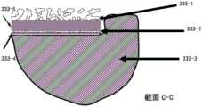
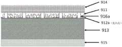
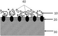
关节假体常用的人工材料是钛合金/钴铬钢合金/不锈钢等,和骨头无法形成有效的生物或化学结合。假体和骨之间的界面一般主要通过物理/机械结合。比如,高度抛光的假体表面和骨组织无法形成有效的结合力,所以,需要增加骨传导、骨诱导、骨再生,以加速或加强骨组织与假体表面的结合,进一步提高骨长上或骨长入的性能。有时钛丝或钛珠等可以用烧结或扩散焊等方法在假体(如髋臼杯/股骨柄)的表面形成多孔性的涂层。或者,用金属 3D打印增材制造工艺、气相沉淀工艺等等,预先制作出具有多孔结构的薄片 0001,然后用扩散焊的方式把薄片0001与假体的实心基底0002结合起来,如图1所示。这些方式为假体提供了多孔性的表面,与假体接触的骨组织能够再生,新的骨组织填充于互相贯通的多孔结构里,达到了“骨长入”假体的效果。但是,这些工艺都有一个不可避免的后果,就是基底的力学强度会大幅降低,从而提高了假体断裂的风险,特别是当假体(比如股骨柄)受到弯曲扭矩或拉伸应力情况下,容易断裂。所以,如何可靠牢固地把一个多孔性结构与其基底结合,同时保证基底力学性能不受太明显的影响成为一个设计/工艺难点。The commonly used artificial materials for joint prostheses are titanium alloy/cobalt-chromium steel alloy/stainless steel, etc., which cannot form an effective biological or chemical bond with bone. The interface between the prosthesis and the bone is generally primarily through physical/mechanical bonding. For example, the highly polished prosthesis surface cannot form an effective bonding force with the bone tissue. Therefore, it is necessary to increase osteoconduction, osteoinduction, and bone regeneration to accelerate or strengthen the combination of bone tissue and the prosthesis surface, and further improve bone growth or growth. The performance of bone ingrowth. Sometimes titanium wires or titanium beads can be used to form porous coatings on the surface of prostheses (such as acetabular cups/femoral stems) by sintering or diffusion welding. Alternatively, use metal 3D printing additive manufacturing process, vapor deposition process, etc., to pre-fabricate a
相对而言,焊接工艺对基底的力学性能影响较低。但是,当多孔性结构的孔隙率很高时(>50%),互相连接的支架占比较低,而且薄弱;支架之间形成大量孔隙。这样的高孔隙率结构无论用金属3D打印增材制造工艺实现,还是通过烧结等方式实现,在采用渗透焊对多孔性结构和基底进行连接时,由于处于高温高压条件下,基底结构的强度会大幅降低。Relatively speaking, the welding process has less influence on the mechanical properties of the substrate. However, when the porosity of the porous structure is high (>50%), the proportion of interconnected scaffolds is low and weak; a large number of pores are formed between the scaffolds. Whether such a high-porosity structure is realized by a metal 3D printing additive manufacturing process or by sintering, when the porous structure and the substrate are connected by penetration welding, the strength of the substrate structure will be reduced due to the high temperature and high pressure conditions. significantly reduce.
基于上述原因,研发一种既能多孔性结构与基底之间的结合强度,还能避免热压工艺(如渗透焊工艺)等造成基底的力学性能大幅下降的方法实为必要。Based on the above reasons, it is necessary to develop a method that can not only achieve the bonding strength between the porous structure and the substrate, but also avoid the significant decrease in the mechanical properties of the substrate caused by the hot pressing process (such as the penetration welding process).
发明内容SUMMARY OF THE INVENTION
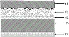
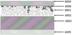
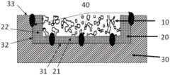
本发明的目的在于提供一种多孔性表面结构和基底的连接结构、制备方法与装置及假体,在多孔性表面结构和基底之间的空隙内设置高分子材料层,使得多孔性表面结构与基底紧密联结,既保证连接结构的基本强度,还能改善应力屏蔽现象,解决现有技术中术后骨溶的问题;本发明还可在基底上预设一预连复合体,该预连复合体包含预先连接的另一多孔结构和中间体,将预连复合体与基底通过各种方法(包括激光焊、电阻焊等)预先进行结合后,再通过高分子材料层将带有预连复合体的基底与多孔性表面结构紧密联结,可防止高分子材料层与其表面的多孔结构形成的结构体与表面光滑的基底之间发生相对运动甚至脱落;基于本发明的多孔性结构的表面,可以保证人工植入假体具备优良的骨长入性能,且使基底的强度不受实质性影响,而且整体复合结构刚度优化降低应力屏蔽风险。The purpose of the present invention is to provide a connection structure, preparation method and device and prosthesis between the porous surface structure and the substrate, and a polymer material layer is arranged in the gap between the porous surface structure and the substrate, so that the porous surface structure and The bases are tightly connected, which not only ensures the basic strength of the connection structure, but also improves the stress shielding phenomenon and solves the problem of postoperative osteolysis in the prior art; the present invention can also preset a pre-connected complex on the base. The body contains another porous structure and an intermediate body that are pre-connected. After the pre-connected composite body and the substrate are pre-bonded by various methods (including laser welding, resistance welding, etc.) The substrate of the composite is closely connected with the porous surface structure, which can prevent the relative movement or even fall off between the structure formed by the polymer material layer and the porous structure on the surface and the substrate with smooth surface; based on the surface of the porous structure of the present invention, It can ensure that the artificial implantation prosthesis has excellent bone ingrowth performance, and the strength of the base is not substantially affected, and the overall composite structure stiffness is optimized to reduce the risk of stress shielding.
为了达到上述目的,本发明通过以下技术方案实现:In order to achieve the above object, the present invention realizes through the following technical solutions:
(一)本发明提供了一种用于制备多孔性表面结构和基底的连接结构的方法,该方法包含:(1) The present invention provides a method for preparing a porous surface structure and a connecting structure of a substrate, the method comprising:
将所述多孔性表面结构与所述基底之间留有间隙;leaving a gap between the porous surface structure and the substrate;
在所述间隙内设置熔融状的热塑性材料;disposing molten thermoplastic material in the gap;
所述熔融状的热塑性材料渗透到所述多孔性表面结构内部,且所述热塑性材料与所述基底接触;The molten thermoplastic material penetrates the interior of the porous surface structure, and the thermoplastic material is in contact with the substrate;
凝固后的热塑性材料将所述多孔性表面结构与所述基底进行连接,所述多孔性表面结构位于所述基底的表面。The solidified thermoplastic material connects the porous surface structure to the substrate, the porous surface structure being located on the surface of the substrate.
优选地,所述热塑性材料为高分子材料。Preferably, the thermoplastic material is a polymer material.
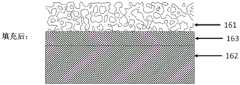
优选地,所述多孔性表面结构的靠近基底的一侧称为内侧,所述间隙是多孔性表面结构内侧设置的一间隔层与所述基底之间的孔隙部分,所述间隔层用于阻挡所述热塑性材料过度渗透。Preferably, the side of the porous surface structure close to the substrate is called the inner side, and the gap is a pore portion between a spacer layer disposed inside the porous surface structure and the substrate, and the spacer layer is used for blocking Excessive penetration of the thermoplastic material.
优选地,所述间隔层为实心结构或多孔结构;Preferably, the spacer layer is a solid structure or a porous structure;
所述多孔性表面结构与所述间隔层一体成型。The porous surface structure is integrally formed with the spacer layer.
优选地,所述的方法,进一步包含:通过向所述间隙内注入熔融状的热塑性材料和/或在所述间隙内放置热塑性材料而后加温熔融,形成熔融状的热塑性材料。Preferably, the method further comprises: forming a molten thermoplastic material by injecting a molten thermoplastic material into the gap and/or placing the thermoplastic material in the gap and then heating and melting.
优选地,所述基底为实心结构,凝固后的热塑性材料和将所述多孔性表面结构的结合体包裹在所述基底的表面;Preferably, the substrate is a solid structure, and the solidified thermoplastic material and the combination of the porous surface structure are wrapped on the surface of the substrate;
或者,所述基底是多孔结构,熔融状的热塑性材料分别渗透到所述多孔性表面结构和所述基底的内部,使得凝固后的热塑性材料将所述多孔性表面结构与所述基底进行联结。Alternatively, the substrate is a porous structure, and the molten thermoplastic material penetrates into the porous surface structure and the interior of the substrate, respectively, so that the solidified thermoplastic material binds the porous surface structure and the substrate.
本发明还提供一种采用如上文(一)所述的方法的连接结构,所述连接结构包含多孔性表面结构和基底,所述多孔性表面结构与所述基底之间留有间隙,通过间隙内的熔融状的热塑性材料渗透到所述多孔性表面结构内部,且与所述基底接触,使得凝固后的热塑性材料将所述多孔性表面结构与所述基底进行连接,所述多孔性表面结构位于所述基底的表面。The present invention also provides a connection structure using the method described in (1) above, the connection structure comprising a porous surface structure and a substrate, a gap is left between the porous surface structure and the substrate, and a gap passes through the gap The molten thermoplastic material inside penetrates into the porous surface structure and contacts the substrate, so that the solidified thermoplastic material connects the porous surface structure with the substrate, the porous surface structure on the surface of the substrate.
优选地,所述热塑性材料为高分子材料。Preferably, the thermoplastic material is a polymer material.
优选地,所述多孔性表面结构的靠近基底的一侧称为内侧,所述间隙是多孔性表面结构内侧设置的一间隔层与所述基底之间的孔隙部分,所述间隔层用于阻挡所述热塑性材料过度渗透。Preferably, the side of the porous surface structure close to the substrate is called the inner side, and the gap is a pore portion between a spacer layer disposed inside the porous surface structure and the substrate, and the spacer layer is used for blocking Excessive penetration of the thermoplastic material.
优选地,所述间隔层为实心结构或多孔结构;所述多孔性表面结构与所述间隔层一体成型。Preferably, the spacer layer is a solid structure or a porous structure; the porous surface structure is integrally formed with the spacer layer.
优选地,所述基底为实心结构,凝固后的热塑性材料和将所述多孔性表面结构的结合体包裹在所述基底的表面;或者,所述基底是多孔结构,熔融状的热塑性材料分别渗透到所述多孔性表面结构和所述基底的内部,使得凝固后的热塑性材料将所述多孔性表面结构与所述基底进行联结。Preferably, the substrate is a solid structure, and the solidified thermoplastic material and the combination of the porous surface structure are wrapped on the surface of the substrate; or, the substrate is a porous structure, and the molten thermoplastic material penetrates respectively to the interior of the porous surface structure and the substrate, so that the solidified thermoplastic material bonds the porous surface structure to the substrate.
与上述(一)部分对应,本发明还提供了一种假体,设置一连接结构,所述连接结构包含多孔性表面结构和基底,所述基底用于形成假体主体;所述假体主体的至少部分表面作为连接区域,且所述多孔性表面结构与所述假体主体的连接区域之间留有间隙,通过间隙内的熔融状的热塑性材料渗透到所述多孔性表面结构内部,且与所述假体主体的连接区域接触,使得凝固后的热塑性材料将所述多孔性表面结构与所述假体主体进行连接,所述多孔性表面结构位于所述假体主体的连接区域。Corresponding to the above-mentioned part (1), the present invention also provides a prosthesis, which is provided with a connecting structure, and the connecting structure includes a porous surface structure and a base, and the base is used to form a prosthesis body; the prosthesis body At least part of the surface is used as a connecting region, and a gap is left between the porous surface structure and the connecting region of the prosthesis body, and the molten thermoplastic material in the gap penetrates into the porous surface structure, and Contacting the connecting region of the prosthesis body causes the solidified thermoplastic material to connect the porous surface structure with the prosthetic body, the porous surface structure being located at the connecting region of the prosthetic body.
优选地,所述假体是关节假体。Preferably, the prosthesis is a joint prosthesis.
优选地,所述多孔性表面结构与热塑性材料的结合体形成为壳体,包覆在所述假体主体的连接区域上;Preferably, the combination of the porous surface structure and the thermoplastic material is formed as a shell, covering the connection area of the prosthesis body;
所述壳体的外层包含所述多孔性表面结构;the outer layer of the shell comprises the porous surface structure;
所述壳体的内层包含热塑性材料,其与所述假体主体的连接区域接触。The inner layer of the shell comprises a thermoplastic material which is in contact with the connection area of the prosthesis body.
优选地,所述结合体形成的壳体是一个整体;Preferably, the housing formed by the combination is a whole;
或者,所述结合体形成的壳体包含多个壳体片体;其中,多个壳体片体相互独立,或者相邻的壳体片体之间在至少一侧的邻边相连接。Alternatively, the casing formed by the combination includes a plurality of casing sheets; wherein the plurality of casing sheets are independent of each other, or adjacent casing sheets are connected on at least one adjacent edge.
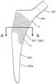
优选地,所述假体包含髋关节的股骨柄,所述股骨柄包含柄体,其形成为基底;所述连接区域的位置为柄体上部的表面。Preferably, the prosthesis comprises a femoral stem of a hip joint, the femoral stem comprising a stem body formed as a base; the location of the connection region is the upper surface of the stem body.
优选地,所述柄体下部的表面为光滑表面,所述柄体下部开设若干纵向的沟槽,所述柄体下部插入股骨髓腔。Preferably, the surface of the lower part of the handle body is a smooth surface, the lower part of the handle body is provided with several longitudinal grooves, and the lower part of the handle body is inserted into the femoral medullary cavity.
优选地,所述股骨柄还包含头部和颈部,所述头部、颈部和所述柄体是一体的或是组装形成;所述股骨柄的头部为锥台结构,其第一端通过颈部与柄体连接,头部与颈部相对柄体有一定的偏转角度,以相对于柄体一侧倾斜的形式布置,股骨柄的头部的第二端插入至股骨球头。Preferably, the femoral stem further comprises a head and a neck, and the head, the neck and the stem are integrated or formed by assembly; the head of the femoral stem is a frustum structure, and its first The end is connected with the handle body through the neck, the head and the neck have a certain deflection angle relative to the handle body, and are arranged in the form of inclination relative to one side of the handle body, and the second end of the head of the femoral stem is inserted into the femoral ball head.
优选地,所述结合体形成为壳体包裹在所述柄体的连接区域外围;所述结合体包含多个壳体片体。Preferably, the combination body is formed such that a shell is wrapped around the periphery of the connection area of the handle body; the combination body includes a plurality of shell pieces.
优选地,所述假体包含髋关节的髋臼杯,所述髋臼杯包含内侧的杯体主体,其形成为基底;所述连接区域的位置为髋臼杯的外周面。Preferably, the prosthesis comprises an acetabular cup of the hip joint, the acetabular cup comprises an inner cup body formed as a base; the location of the connection region is the outer peripheral surface of the acetabular cup.
优选地,所述假体包含胫骨平台,所述胫骨平台包含胫骨托,其形成为基底;所述连接区域的位置为胫骨托的远端的表面。Preferably, the prosthesis comprises a tibial plateau comprising a tibial tray formed as a base; the location of the attachment region is the surface of the distal end of the tibial tray.
优选地,所述假体包含股骨髁,所述股骨髁包含髁内固定面,其形成为基底;所述连接区域的位置为髁内固定面。Preferably, the prosthesis includes a femoral condyle, and the femoral condyle includes an intracondylar fixation surface, which is formed as a base; the location of the connection area is the intracondylar fixation surface.
优选地,所述假体是以下的任意一种或多种:髌骨、脊柱融合器、脊柱椎间小平面关节、踝关节、肩关节、肘关节、指关节、趾关节、人工椎间盘、下颌关节、腕关节。Preferably, the prosthesis is any one or more of the following: patella, spinal cage, spinal facet joint, ankle joint, shoulder joint, elbow joint, finger joint, toe joint, artificial intervertebral disc, mandibular joint ,LOL.
优选地,所述热塑性材料为高分子材料。Preferably, the thermoplastic material is a polymer material.
优选地,所述多孔性表面结构的靠近基底的一侧称为内侧,所述间隙是多孔性表面结构内侧设置的一间隔层与所述基底之间的孔隙部分,所述间隔层用于阻挡所述热塑性材料过度渗透。Preferably, the side of the porous surface structure close to the substrate is called the inner side, and the gap is a pore portion between a spacer layer disposed inside the porous surface structure and the substrate, and the spacer layer is used for blocking Excessive penetration of the thermoplastic material.
优选地,所述间隔层为实心结构或多孔结构;所述多孔性表面结构与所述间隔层一体成型。Preferably, the spacer layer is a solid structure or a porous structure; the porous surface structure is integrally formed with the spacer layer.
优选地,所述基底为实心结构,凝固后的热塑性材料和将所述多孔性表面结构的结合体包裹在所述基底的表面;或者,所述基底是多孔结构,熔融状的热塑性材料分别渗透到所述多孔性表面结构和所述基底的内部,使得凝固后的热塑性材料将所述多孔性表面结构与所述基底进行联结。Preferably, the substrate is a solid structure, and the solidified thermoplastic material and the combination of the porous surface structure are wrapped on the surface of the substrate; or, the substrate is a porous structure, and the molten thermoplastic material penetrates respectively to the interior of the porous surface structure and the substrate, so that the solidified thermoplastic material bonds the porous surface structure to the substrate.
(二)本发明又提供了一种用于制备多孔性表面结构和基底的连接结构的方法,该方法包含:(2) The present invention also provides a method for preparing the connection structure of the porous surface structure and the substrate, the method comprising:
基底上设置至少一预连多孔结构,预连多孔结构与基底预先连接;At least one pre-connected porous structure is arranged on the base, and the pre-connected porous structure is pre-connected to the base;
将所述预连多孔结构的远离基底的一侧与所述多孔性表面结构的靠近基底的一侧之间留有间隙;leaving a gap between the side of the pre-connected porous structure away from the substrate and the side of the porous surface structure close to the substrate;
在所述间隙内设置熔融状的热塑性材料;disposing molten thermoplastic material in the gap;
所述熔融状的热塑性材料分别渗透到所述多孔性表面结构和所述预连多孔结构的内部;The molten thermoplastic material penetrates into the porous surface structure and the interior of the preconnected porous structure, respectively;
凝固后的热塑性材料将所述多孔性表面结构与所述预连多孔结构进行连接,所述多孔性表面结构位于所述基底的表面。The solidified thermoplastic material joins the porous surface structure on the surface of the substrate with the pre-connected porous structure.
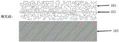
优选地,所述多孔性表面结构的靠近基底的一侧称为内侧,所述间隙是多孔性表面结构内侧设置的一间隔层与所述预连多孔结构的远离基底的一侧之间的孔隙部分,所述间隔层用于阻挡所述热塑性材料过度渗透。Preferably, the side of the porous surface structure close to the substrate is referred to as the inner side, and the gap is the pore between a spacer layer provided inside the porous surface structure and the side of the pre-connected porous structure away from the substrate In part, the spacer layer is used to block excessive penetration of the thermoplastic material.
优选地,所述间隔层为实心结构或多孔结构;所述多孔性表面结构与所述间隔层一体成型。Preferably, the spacer layer is a solid structure or a porous structure; the porous surface structure is integrally formed with the spacer layer.
优选地,所述的方法进一步包含:通过向所述间隙内注入熔融状的热塑性材料和/或在所述间隙内放置热塑性材料而后加温熔融,形成熔融状的热塑性材料。Preferably, the method further comprises: forming the molten thermoplastic material by injecting the molten thermoplastic material into the gap and/or placing the thermoplastic material in the gap and then heating and melting.
优选地,所述预连多孔结构的靠近基底的一侧与所述基底的靠近多孔性表面结构的一侧是通过激光焊接和/或电阻焊接进行预先连接。Preferably, the side of the pre-connected porous structure and the side of the substrate near the porous surface structure are pre-connected by laser welding and/or resistance welding.
优选地,当采用电阻焊接时,进一步包含:Preferably, when resistance welding is adopted, it further comprises:
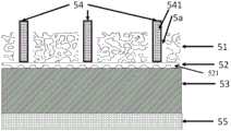
预连多孔结构的至少部分与所述基底直接接触,所述基底和所述预连多孔结构置于第一极性电极和第二极性电极之间,所述第一极性电极与所述预连多孔结构导电接触,所述基底与所述第二极性电极导电接触,形成电流回路,使得预连多孔结构与基底的接触部分与基底进行电阻焊接;At least part of the pre-connected porous structure is in direct contact with the substrate, the substrate and the pre-connected porous structure are interposed between a first polarity electrode and a second polarity electrode, the first polarity electrode and the The pre-connected porous structure is in conductive contact, and the substrate is in conductive contact with the second polarity electrode to form a current loop, so that the contact portion of the pre-connected porous structure and the substrate is resistance welded with the substrate;
和/或,预连多孔结构与基底之间设置中间体且所述中间体与所述预连多孔结构形成一预连复合体,所述预连复合体与所述基底置于所述第一极性电极和所述第二极性电极之间,所述第一极性电极与所述预连多孔结构和/或中间体导电接触,所述基底与所述第二极性电极导电接触,形成电流回路,使得所述中间体和所述基底进行电阻焊接,实现所述预连复合体与所述基底之间的连接。And/or, an intermediate is arranged between the pre-connected porous structure and the substrate, and the intermediate and the pre-connected porous structure form a pre-connected composite body, and the pre-connected composite body and the substrate are placed in the first between the polarity electrode and the second polarity electrode, the first polarity electrode is in conductive contact with the preconnected porous structure and/or the intermediate body, the substrate is in conductive contact with the second polarity electrode, A current loop is formed, so that the intermediate body and the substrate undergo resistance welding, so as to realize the connection between the pre-connected composite body and the substrate.
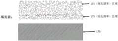
优选地,所述预连复合体中的预连多孔结构称为第一多孔结构;所述中间体是实心结构,或者,所述中间体是第二多孔结构并且所述第二多孔结构的孔隙率低于所述第一多孔结构的孔隙率。Preferably, the pre-connected porous structure in the pre-connected composite is referred to as a first porous structure; the intermediate is a solid structure, or the intermediate is a second porous structure and the second porous structure The porosity of the structure is lower than the porosity of the first porous structure.
优选地,所述电阻焊接为凸焊式电阻焊和/或点焊式电阻焊。Preferably, the resistance welding is projection welding resistance welding and/or spot welding resistance welding.
优选地,当所述电阻焊接为凸焊式电阻焊时,所述第一极性电极是连续的平面电极或分段的多个电极单体,所述第二极性电极是连续的平面电极或分段的多个电极单体;当所述电阻焊接为点焊式电阻焊时,所述第一极性电极和/或所述第二极性电极是分段的多个电极单体。Preferably, when the resistance welding is projection welding, the first polarity electrode is a continuous planar electrode or a plurality of segmented electrode units, and the second polarity electrode is a continuous planar electrode or a plurality of segmented electrode units; when the resistance welding is spot welding resistance welding, the first polarity electrode and/or the second polarity electrode is a segmented plurality of electrode units.
优选地,当点焊式电阻焊时,通过移动以下任意一个或多个部件:第一极性电极、第二极性电极、已在至少一个接触位置完成焊接的中间体与基底的结合体,使得从当前焊接位置移动到下一焊接位置。Preferably, during spot welding resistance welding, by moving any one or more of the following components: the first polarity electrode, the second polarity electrode, the combination of the intermediate body and the base that has been welded at at least one contact position, Causes movement from the current welding position to the next welding position.
优选地,所述第一极性电极分成多个电极单体时,所述电极单体插入至预连多孔结构内的预制空隙,电极单体靠近所述中间体,使得插入后的所述电极单体与所述中间体导电接触或者使得插入后的所述电极单体经过预连多孔结构与所述中间体导电接触。Preferably, when the first polarity electrode is divided into a plurality of electrode cells, the electrode cells are inserted into the prefabricated voids in the preconnected porous structure, and the electrode cells are close to the intermediate body, so that the inserted electrode is The monomer is in conductive contact with the intermediate or the inserted electrode monomer is in conductive contact with the intermediate through the pre-connected porous structure.
优选地,所述电极单体从预连多孔结构的表面穿过直至穿透至中间体表面或中间体的内部,使得插入后的所述电极单体与所述中间体导电接触。Preferably, the electrode monomer penetrates from the surface of the pre-connected porous structure until it penetrates to the surface of the intermediate body or the interior of the intermediate body, so that the inserted electrode monomer is in conductive contact with the intermediate body.
优选地,所述电极单体与所述预连多孔结构为侧向间隙配合,使得所述电极单体与所述预连多孔结构完全不接触。Preferably, the electrode monomer and the pre-connected porous structure are in a lateral gap fit, so that the electrode monomer and the pre-connected porous structure are not in contact with each other at all.
优选地,所述多个电极单体并联连接至另一平面电极且所述另一平面电极与电源端连接,或者,所述多个电极单体并联并直接连接至电源端。Preferably, the plurality of electrode units are connected in parallel to another planar electrode and the other planar electrode is connected to the power terminal, or the plurality of electrode units are connected in parallel and directly to the power terminal.
优选地,所述第一极性电极为柔性电极,所述柔性电极在压力作用下,通过柔性变形使得其与所述预连多孔结构表面相匹配,增大所述柔性电极与所述预连多孔结构表面的接触面积。Preferably, the first polarity electrode is a flexible electrode, and under the action of pressure, the flexible electrode is flexibly deformed to match the surface of the pre-connected porous structure, so as to increase the relationship between the flexible electrode and the pre-connected porous structure. The contact area of the porous structure surface.
优选地,所述第一极性电极为正电极,所述第二极性电极为负电极;或者,所述第一极性电极为负电极,所述第二极性电极为正电极。Preferably, the first polarity electrode is a positive electrode, and the second polarity electrode is a negative electrode; or, the first polarity electrode is a negative electrode, and the second polarity electrode is a positive electrode.
优选地,所述第一极性电极和所述第二极性电极由导电材料制成;所述基底由导电材料制成,所述预连多孔结构由导电材料制成,所述中间体由导电材料制成。Preferably, the first polarity electrode and the second polarity electrode are made of conductive material; the substrate is made of conductive material, the pre-connected porous structure is made of conductive material, and the intermediate is made of Made of conductive material.
优选地,所述中间体包含中间板结构。Preferably, the intermediate comprises an intermediate plate structure.
优选地,所述中间板结构上设置多个凸起结构,所述凸起结构设置在所述中间板结构上靠近所述基底的一侧,所述凸起结构的凸点与所述基底接触。Preferably, a plurality of raised structures are arranged on the intermediate plate structure, the raised structures are arranged on a side of the intermediate plate structure close to the base, and the bumps of the raised structures are in contact with the base .
优选地,所述中间体是所述第二多孔结构,所述第二多孔结构包含多个凸起结构,所述凸起结构形成在所述第二多孔结构上靠近所述基底的一侧,所述凸起结构的凸点与所述基底接触。Preferably, the intermediate body is the second porous structure, the second porous structure includes a plurality of raised structures, and the raised structures are formed on the second porous structure close to the substrate On one side, the bumps of the raised structures are in contact with the substrate.
优选地,所述中间体包含若干个分散布置的凸起结构,形成在所述预连多孔结构靠近基底的一侧,所述凸起结构的凸点与所述基底接触。Preferably, the intermediate body includes a plurality of dispersedly arranged protruding structures formed on the side of the pre-connected porous structure close to the substrate, and the bumps of the protruding structures are in contact with the substrate.
优选地,所述中间体包含若干支撑柱,每个支撑柱的全部或至少部分位于预连多孔结构内。Preferably, the intermediate body comprises several support posts, all or at least part of each support post being located within the pre-connected porous structure.
优选地,所述中间体的支撑柱与所述中间体的凸起结构对应布置并接触,或所述中间体的支撑柱与所述中间体的凸起结构错位分布且不接触。Preferably, the support columns of the intermediate body are arranged correspondingly and in contact with the convex structures of the intermediate body, or the support columns of the intermediate body and the convex structures of the intermediate body are dislocated and distributed and not in contact.
优选地,所述支撑柱的远离基底一侧的表面超出所述预连多孔结构的表面;或者,所述支撑柱的远离基底一侧的表面低于所述预连多孔结构的表面;或者,所述支撑柱的远离基底一侧的表面与所述预连多孔结构的表面平齐。Preferably, the surface of the support column on the side away from the substrate exceeds the surface of the pre-connected porous structure; or, the surface of the support column on the side away from the substrate is lower than the surface of the pre-connected porous structure; or, The surface of the support column on the side away from the substrate is flush with the surface of the preconnected porous structure.
优选地,所述支撑柱的远离基底一侧的表面超出所述预连多孔结构的表面时,在电阻焊完成后,切割所述支撑柱超出所述预连多孔结构的部分。Preferably, when the surface of the support column on the side away from the substrate extends beyond the surface of the pre-connected porous structure, after the resistance welding is completed, the part of the support column beyond the pre-connected porous structure is cut.
优选地,所述第一极性电极分成多个电极单体时,所述支撑柱位于所述预连多孔结构的预制空隙内,所述支撑柱开设凹槽,用于放置所述电极单体,插入后的所述电极单体与所述支撑柱导电接触;所述支撑柱的表面超出或平齐于或低于所述预连多孔结构的表面,所述支撑柱为多孔结构或实心结构。Preferably, when the first polarity electrode is divided into a plurality of electrode units, the support column is located in the prefabricated space of the pre-connected porous structure, and the support column is provided with a groove for placing the electrode unit. , the inserted electrode monomer is in conductive contact with the support column; the surface of the support column exceeds or is flush with or lower than the surface of the pre-connected porous structure, and the support column is a porous structure or a solid structure .
优选地,所述支撑柱的远离基底一侧的表面超出所述预连多孔结构的表面时:所述支撑柱为多段结构,至少包含超出所述预连多孔结构的第一段部分和剩余的第二段部分;所述第一段部分为多孔结构;所述第二段部分为多孔结构或实心结构,所述第二段部分上远离基底一侧的表面平齐于所述预连多孔结构的表面,使得第一段部分因与第一极性电极接触生热导致所述支撑柱下沉至所述第二段部分的远离基底一侧的表面。Preferably, when the surface of the support column on the side away from the substrate exceeds the surface of the pre-connected porous structure: the support column is a multi-segment structure, including at least the first section beyond the pre-connected porous structure and the remaining part of the pre-connected porous structure. The second section; the first section is a porous structure; the second section is a porous structure or a solid structure, and the surface of the second section away from the substrate is flush with the pre-connected porous structure The surface of the second segment portion is caused to sink to the surface of the second segment portion away from the substrate due to heat generation of the first segment portion due to contact with the first polarity electrode.
优选地,所述支撑柱为导电体时,所述支撑柱接入到所述电流回路,所述支撑柱与以下任意一个或多个部件导电接触:第一极性电极、预连多孔结构、中间体。Preferably, when the support column is a conductor, the support column is connected to the current loop, and the support column is in conductive contact with any one or more of the following components: a first polarity electrode, a pre-connected porous structure, Intermediate.
优选地,所述支撑柱为绝缘体。Preferably, the support column is an insulator.
优选地,所述凸起结构位于所述中间体上的位置,靠近所述预连多孔结构与所述中间体的接触位置。Preferably, the protruding structure is located at a position on the intermediate body, close to the contact position of the pre-connected porous structure and the intermediate body.
优选地,所述预连多孔结构内至少部分的孔隙内填充导电材料。Preferably, at least part of the pores in the preconnected porous structure is filled with conductive material.
优选地,所述预连多孔结构内至少部分的孔隙内填充粉末状的导电材料或丝材状的导电材料或网状的导电材料。Preferably, at least part of the pores in the pre-connected porous structure is filled with powdered conductive material, wire-shaped conductive material or mesh-shaped conductive material.
优选地,预连多孔结构的至少部分的表面铺设固体薄膜状或丝状或网状的可变形导电介质,所述可变形导电介质位于所述第一极性电极和所述预连多孔结构之间;和/或,至少部分的预连多孔结构的表面与所述第一极性电极之间喷涂固态导电介质或液态导电剂。Preferably, at least part of the surface of the pre-connected porous structure is covered with a solid film-like or filament-like or mesh-like deformable conductive medium, and the deformable conductive medium is located between the first polarity electrode and the pre-connected porous structure. and/or, a solid conductive medium or a liquid conductive agent is sprayed between at least part of the surface of the preconnected porous structure and the first polarity electrode.
优选地,至少部分的预连多孔结构的孔隙内注入熔融状的导电介质,和/ 或,至少部分的预连多孔结构的孔隙内置导电介质并通过高温使导电介质成熔融状;所述导电介质的熔点低于基底的熔点和/或预连多孔结构的熔点。Preferably, a molten conductive medium is injected into at least part of the pores of the pre-connected porous structure, and/or, at least a part of the pores of the pre-connected porous structure has a built-in conductive medium and the conductive medium is melted by high temperature; the conductive medium The melting point is lower than the melting point of the substrate and/or the melting point of the pre-connected porous structure.
优选地,所述预连多孔结构表面设置若干个凹槽,所述凹槽的表面低于所述预连多孔结构表面,将所述预连多孔结构划分成多个区域;经所述凹槽划分出的各区域,均被该区域对应接触的第一极性电极覆盖,所述预连多孔结构的任意一区域与邻近凹槽的位置关系是以下的任意一种:与凹槽第一侧不接触、跨过凹槽第一侧且不超出凹槽第二侧、跨过凹槽第一侧直至凹槽第二侧、跨过凹槽第二侧并接触到邻近的另一区域的至少一部分;其中,凹槽的第一侧为靠近所述任意一区域的一侧,凹槽的第二侧为远离所述任意一区域的一侧。Preferably, the surface of the pre-connected porous structure is provided with several grooves, the surface of the groove is lower than the surface of the pre-connected porous structure, and the pre-connected porous structure is divided into multiple regions; Each divided area is covered by the first polarity electrode corresponding to the area, and the positional relationship between any area of the pre-connected porous structure and the adjacent groove is any one of the following: with the first side of the groove Not touching, spanning the first side of the groove and not beyond the second side of the groove, spanning the first side of the groove up to the second side of the groove, spanning the second side of the groove and touching at least one adjacent area Wherein, the first side of the groove is the side close to any one of the regions, and the second side of the groove is the side away from the any one of the regions.
优选地,凹槽划分的相邻两区域的预连多孔结构与基底之间的电阻焊过程是分别通过覆盖位置不相重合的两个不同的第一极性电极同时进行;或者,凹槽划分的相邻两区域的预连多孔结构与基底之间的电阻焊过程是分别通过两个不同的第一极性电极按先后次序分两次进行;或者,凹槽划分的相邻两区域的预连多孔结构与基底之间的电阻焊过程是通过同一个第一极性电极按先后次序分两次进行。Preferably, the resistance welding process between the pre-connected porous structure and the substrate in two adjacent regions divided by the grooves is performed simultaneously by covering two different first polarity electrodes whose positions do not coincide; or, the grooves are divided The resistance welding process between the pre-connected porous structure of the two adjacent regions and the substrate is carried out twice in sequence through two different first polarity electrodes; or, the pre-connection of the two adjacent regions divided by the groove The resistance welding process between the porous structure and the substrate is performed twice in sequence through the same first polarity electrode.
优选地,所述凹槽为长条状。Preferably, the grooves are elongated.
优选地,所述第二极性电极为连续的平面电极;或者,所述第二极性电极分为多个区域的第二极性电极,分别与各个区域相匹配。Preferably, the second polarity electrode is a continuous planar electrode; or, the second polarity electrode is divided into a plurality of regions of the second polarity electrode, which are respectively matched with each region.
优选地,将预连多孔结构划分成多个区域,划分的任意相邻的两个区域称为第一区域的多孔结构和第二区域的多孔结构;第一区域的多孔结构与对应的第一区域的一第一极性电极接触,完成第一区域的多孔结构与基底的电阻焊接后,所述第一区域的多孔结构与所述第一区域的第一极性电极的接触边缘形成凸边;所述第二区域的多孔结构与对应的第二区域的一第一极性电极接触,第二区域的一第一极性电极至少覆盖到第一区域的多孔结构上靠近第二区域的多孔结构一侧的凸边,完成第二区域的多孔结构与基底的电阻焊接。Preferably, the preconnected porous structure is divided into a plurality of regions, and any two adjacent regions divided are referred to as the porous structure of the first region and the porous structure of the second region; the porous structure of the first region and the corresponding first region A first polarity electrode in the first region is in contact, and after the resistance welding between the porous structure in the first region and the substrate is completed, the contact edge between the porous structure in the first region and the first polarity electrode in the first region forms a convex edge The porous structure of the second area is in contact with a first polarity electrode of the corresponding second area, and a first polarity electrode of the second area covers at least the porous structure of the first area and is close to the porous structure of the second area. The convex edge on one side of the structure completes the resistance welding of the porous structure in the second area and the substrate.
优选地,所述第二极性电极为连续的平面电极;或者,所述第二极性电极分为多个区域的第二极性电极,分别与各个区域相匹配。Preferably, the second polarity electrode is a continuous planar electrode; or, the second polarity electrode is divided into a plurality of regions of the second polarity electrode, which are respectively matched with each region.
优选地,所述基底包含一表面连接层,所述表面连接层与基底主体预先连接,所述表面连接层介于所述预连复合体的中间体与基底主体之间;所述表面连接层包含凸起结构,所述凸起结构的凸点与所述预连复合体的中间体接触。Preferably, the substrate comprises a surface connection layer, the surface connection layer is pre-connected to the base body, and the surface connection layer is interposed between the intermediate body of the pre-connected composite and the base body; the surface connection layer A protruding structure is included, and the protruding point of the protruding structure is in contact with the intermediate body of the pre-connected composite.
优选地,所述表面连接层与基底主体预先焊接连接。Preferably, the surface connection layer is pre-welded and connected to the base body.
优选地,所述中间体上靠近所述基底的一侧为平面状;或者,所述中间体上靠近所述基底的一侧设置的凸起结构与所述表面连接层的凸起结构错开。Preferably, the side of the intermediate body close to the base is flat; or, the protruding structures provided on the side of the intermediate body close to the base are staggered from the protruding structures of the surface connection layer.
优选地,当采用激光焊接时,进一步包含:预连多孔结构与基底之间设置中间体且所述中间体与所述预连多孔结构形成预连复合体;所述中间体与基底之间有至少一对接触面;所述中间体与基底在两者之间的至少一对接触面通过激光焊接来连接固定。Preferably, when using laser welding, it further comprises: an intermediate is arranged between the pre-connected porous structure and the substrate, and the intermediate and the pre-connected porous structure form a pre-connected composite; there is a pre-connected composite between the intermediate and the substrate At least one pair of contact surfaces; the at least one pair of contact surfaces between the intermediate and the substrate are connected and fixed by laser welding.
优选地,所述基底包含一个连接区域,其与一个预连复合体的中间体接触且连接,或分别与多个预连复合体的中间体接触且连接;或者,所述基底包含多个连接区域,其与同一个预连复合体的中间体接触且连接;或者,所述基底包含多个连接区域,其中的每个连接区域和与之对应的一个预连复合体的中间体接触且连接,或每个连接区域和与之对应的多个预连复合体的中间体分别接触且连接。Preferably, the substrate comprises a connecting region, which is in contact with and is connected to the intermediate of a pre-joined complex, or is in contact with and connected to the intermediates of a plurality of pre-joined complexes respectively; alternatively, the substrate comprises a plurality of joints region, which contacts and connects with the intermediate of the same pre-connected complex; or, the substrate comprises a plurality of connected regions, each of which is in contact with and connected to the intermediate of a corresponding pre-connected complex , or each connecting region and the corresponding intermediates of multiple pre-connected complexes are respectively contacted and connected.
优选地,所述基底包含有多个连接区域时,所述多个连接区域处在同一平面,或者一部分连接区域与该基底上的其他连接区域不处在同一平面;基底上的多个连接区域各自独立布置,或者基底上的至少一部分连接区域与该基底上的其他连接区域相互连通。Preferably, when the substrate includes a plurality of connection regions, the plurality of connection regions are in the same plane, or a part of the connection regions and other connection regions on the substrate are not in the same plane; the plurality of connection regions on the substrate They are each independently arranged, or at least a part of the connection areas on the substrate communicate with other connection areas on the substrate.
优选地,所述中间体与基底在两者之间的至少一对接触面焊接,称一对相互焊接的接触面为一对第一接触面;所述中间体与基底在两者之间的至少一对接触面相应地设置有定位结构,称一对相应设置有定位结构的接触面为一对第二接触面;相应设置有定位结构的第二接触面,属于相互焊接的第一接触面;或者,相应设置有定位结构的第二接触面,不属于相互焊接的第一接触面。Preferably, at least a pair of contact surfaces between the intermediate body and the substrate are welded, and a pair of mutually welded contact surfaces is referred to as a pair of first contact surfaces; At least a pair of contact surfaces are correspondingly provided with positioning structures, and a pair of contact surfaces correspondingly provided with positioning structures are referred to as a pair of second contact surfaces; the second contact surfaces correspondingly provided with positioning structures belong to the first contact surfaces welded to each other ; Or, the second contact surface correspondingly provided with the positioning structure does not belong to the first contact surface welded to each other.
优选地,所述定位结构,包含:限位口,形成在任意一对第二接触面之中的一个接触面;突起,形成在所述任意一对第二接触面之中的另一个接触面,并插入到对应位置的所述限位口内。Preferably, the positioning structure includes: a limit opening formed on one contact surface of any pair of second contact surfaces; a protrusion formed on the other contact surface of any pair of second contact surfaces , and insert it into the limit opening at the corresponding position.
优选地,任意一对第二接触面通过相配合的表面形状及尺寸,来形成定位结构。Preferably, any pair of the second contact surfaces form the positioning structure through the matched surface shapes and sizes.
优选地,所述基底的连接区域包含开设在基底的凹部;所述预连复合体包含嵌置于凹部内的嵌入部分,位于嵌入部分内的中间体与基底凹部之间有至少一对接触面;位于嵌入部分内的中间体与基底凹部在两者之间的至少一对接触面处焊接。Preferably, the connection area of the base includes a concave part opened in the base; the pre-connected composite body includes an embedded part embedded in the concave part, and there are at least one pair of contact surfaces between the intermediate body located in the embedded part and the base concave part ; The intermediate body and the base recess located in the embedded portion are welded at at least one pair of contact surfaces therebetween.
优选地,所述基底的凹部设有开口,以及与所述开口相对的顶面;所述开口与顶面之间设有侧边;位于嵌入部分内的中间体包含底部,所述中间体的底部与基底凹部的顶面之间焊接固定;或者,位于嵌入部分内的中间体包含底部及周边,所述中间体的底部与基底凹部的顶面之间焊接固定,和/或所述中间体的至少一侧周边与基底凹部的至少一侧侧边之间焊接固定。Preferably, the recess of the base is provided with an opening, and a top surface opposite to the opening; a side edge is provided between the opening and the top surface; the intermediate body located in the embedded part includes a bottom, and the intermediate body is provided with a bottom. The bottom and the top surface of the base recess are welded and fixed; alternatively, the intermediate body located in the embedded portion includes the bottom and the periphery, the bottom of the intermediate body is welded and fixed between the top surface of the base recess, and/or the intermediate body At least one side of the periphery of the base is welded and fixed with at least one side of the base recess.
优选地,所述中间体与基底在两者之间的至少一对接触面,通过相配合的表面形成定位结构;所述定位结构,包含:基底凹部的至少一个侧边为斜面,其与基底凹部的顶面形成设定的角度;与所述至少一个侧边相对应的所述中间体的至少一个周边为斜面,其与所述中间体的底部形成设定的角度。Preferably, at least a pair of contact surfaces between the intermediate body and the base form a positioning structure through the matching surfaces; the positioning structure includes: at least one side of the base recess is an inclined surface, which is connected to the base. The top surface of the recess forms a set angle; at least one periphery of the intermediate body corresponding to the at least one side edge is an inclined surface, which forms a set angle with the bottom of the intermediate body.
优选地,所述角度为锐角。Preferably, the angle is an acute angle.
优选地,所述预连复合体的中间体为板状或片状。Preferably, the intermediate body of the pre-connected composite body is in the shape of a plate or a sheet.
优选地,所述基底是实心结构,或者,所述基底是第三多孔结构且所述第三多孔结构的孔隙率小于所述预连多孔结构的孔隙率。Preferably, the substrate is a solid structure, or the substrate is a third porous structure and the porosity of the third porous structure is smaller than the porosity of the pre-connected porous structure.
优选地,所述基底通过锻造或铸造或机加工或或粉末冶金或金属注射成型工艺制成。Preferably, the substrate is made by forging or casting or machining or either powder metallurgy or metal injection moulding processes.
优选地,所述预连复合体的预连多孔结构与中间体一体成型。Preferably, the pre-connected porous structure of the pre-connected composite body is integrally formed with the intermediate body.
优选地,所述预连复合体的预连多孔结构与中间体,通过3D打印增材制造工艺、或气相沉淀工艺实现。Preferably, the pre-connected porous structure and the intermediate of the pre-connected composite body are realized by a 3D printing additive manufacturing process or a vapor deposition process.
优选地,所述预连多孔结构、所述中间体和所述支撑柱一体成型。Preferably, the preconnected porous structure, the intermediate body and the support column are integrally formed.
本发明还提供一种采用如上文(二)中所述的方法制成的连接结构,包含多孔性表面结构和基底,所述基底上设有至少一预连多孔结构,用于与所述基底预先连接;所述预连多孔结构的远离基底的一侧与所述多孔性表面结构的靠近基底的一侧之间留有间隙,通过间隙内的熔融状的热塑性材料分别渗透到所述多孔性表面结构和所述预连多孔结构的内部,使得凝固后的热塑性材料将所述多孔性表面结构与所述预连多孔结构进行连接,所述多孔性表面结构位于所述基底的表面。The present invention also provides a connection structure made by the method described in (2) above, comprising a porous surface structure and a substrate, on which the substrate is provided with at least one preconnected porous structure for connecting with the substrate Pre-connected; a gap is left between the side of the pre-connected porous structure away from the substrate and the side of the porous surface structure close to the substrate, and the molten thermoplastic material in the gap penetrates into the porous structure respectively The surface structure and the interior of the pre-connected porous structure are such that the solidified thermoplastic material connects the porous surface structure with the pre-connected porous structure, the porous surface structure being located on the surface of the substrate.
优选地,所述多孔性表面结构的靠近基底的一侧称为内侧,所述间隙是多孔性表面结构内侧设置的一间隔层与所述预连多孔结构的远离基底的一侧之间的孔隙部分,所述间隔层用于阻挡所述热塑性材料过度渗透。Preferably, the side of the porous surface structure close to the substrate is referred to as the inner side, and the gap is the pore between a spacer layer provided inside the porous surface structure and the side of the pre-connected porous structure away from the substrate In part, the spacer layer is used to block excessive penetration of the thermoplastic material.
优选地,所述间隔层为实心结构或多孔结构;所述多孔性表面结构与所述间隔层一体成型。Preferably, the spacer layer is a solid structure or a porous structure; the porous surface structure is integrally formed with the spacer layer.
优选地,所述预连多孔结构的靠近基底的一侧与所述基底的靠近多孔性表面结构的一侧是通过激光焊接和/或电阻焊接进行预先连接。Preferably, the side of the pre-connected porous structure and the side of the substrate near the porous surface structure are pre-connected by laser welding and/or resistance welding.
优选地,所述预连多孔结构的至少部分与所述基底直接接触,所述基底和所述预连多孔结构置于第一极性电极和第二极性电极之间,所述第一极性电极与所述预连多孔结构导电接触,所述基底与第二极性电极导电接触,形成电流回路,使得所述预连多孔结构与基底的接触部分与所述基底进行电阻焊接;和/或,所述预连多孔结构与所述基底之间设置中间体且所述中间体与所述预连多孔结构形成一预连复合体,所述预连复合体与所述基底置于第一极性电极和第二极性电极之间,所述第一极性电极与所述预连多孔结构和/ 或中间体导电接触,所述基底与第二极性电极导电接触,形成电流回路,使得所述中间体和所述基底进行电阻焊接,实现所述预连复合体与所述基底之间的连接。Preferably, at least part of the pre-connected porous structure is in direct contact with the substrate, the substrate and the pre-connected porous structure are interposed between a first polarity electrode and a second polarity electrode, the first electrode and/ Or, an intermediate is arranged between the pre-connected porous structure and the substrate, and the intermediate and the pre-connected porous structure form a pre-connected composite body, and the pre-connected composite body and the substrate are placed in the first between the polarity electrode and the second polarity electrode, the first polarity electrode is in conductive contact with the preconnected porous structure and/or the intermediate body, the substrate is in conductive contact with the second polarity electrode to form a current loop, The intermediate body and the substrate are resistance welded to realize the connection between the pre-connected composite body and the substrate.
优选地,所述预连复合体中的预连多孔结构称为第一多孔结构;所述中间体是实心结构,或者,所述中间体是第二多孔结构并且所述第二多孔结构的孔隙率低于所述第一多孔结构的孔隙率。Preferably, the pre-connected porous structure in the pre-connected composite is referred to as a first porous structure; the intermediate is a solid structure, or the intermediate is a second porous structure and the second porous structure The porosity of the structure is lower than the porosity of the first porous structure.
优选地,所述基底由导电材料制成,所述预连多孔结构由导电材料制成,所述中间体由导电材料制成。Preferably, the substrate is made of conductive material, the pre-connected porous structure is made of conductive material, and the intermediate is made of conductive material.
优选地,所述中间体包含中间板结构。Preferably, the intermediate comprises an intermediate plate structure.
优选地,所述中间板结构上设置多个凸起结构,所述凸起结构设置在所述中间板结构上靠近所述基底的一侧,所述凸起结构的凸点与所述基底接触。Preferably, a plurality of raised structures are arranged on the intermediate plate structure, the raised structures are arranged on a side of the intermediate plate structure close to the base, and the bumps of the raised structures are in contact with the base .
优选地,所述中间体是所述第二多孔结构,所述第二多孔结构包含多个凸起结构,所述凸起结构形成在所述第二多孔结构上靠近所述基底的一侧,所述凸起结构的凸点与所述基底接触。Preferably, the intermediate body is the second porous structure, the second porous structure includes a plurality of raised structures, and the raised structures are formed on the second porous structure close to the substrate On one side, the bumps of the raised structures are in contact with the substrate.
优选地,所述中间体包含若干个分散布置的凸起结构,形成在所述预连多孔结构靠近基底的一侧,所述凸起结构的凸点与所述基底接触。Preferably, the intermediate body includes a plurality of dispersedly arranged protruding structures formed on the side of the pre-connected porous structure close to the substrate, and the bumps of the protruding structures are in contact with the substrate.
优选地,所述中间体包含若干支撑柱,每个支撑柱的全部或至少部分位于预连多孔结构内。Preferably, the intermediate body comprises several support posts, all or at least part of each support post being located within the pre-connected porous structure.
优选地,所述中间体的支撑柱与所述中间体的凸起结构对应布置并接触,或所述中间体的支撑柱与所述中间体的凸起结构错位分布且不接触。Preferably, the support columns of the intermediate body are arranged correspondingly and in contact with the convex structures of the intermediate body, or the support columns of the intermediate body and the convex structures of the intermediate body are dislocated and distributed and not in contact.
优选地,所述支撑柱的远离基底一侧的表面超出所述预连多孔结构的表面;或者,所述支撑柱的远离基底一侧的表面低于所述预连多孔结构的表面;或者,所述支撑柱的远离基底一侧的表面与所述预连多孔结构的表面平齐。Preferably, the surface of the support column on the side away from the substrate exceeds the surface of the pre-connected porous structure; or, the surface of the support column on the side away from the substrate is lower than the surface of the pre-connected porous structure; or, The surface of the support column on the side away from the substrate is flush with the surface of the preconnected porous structure.
优选地,所述支撑柱的远离基底一侧的表面超出所述预连多孔结构的表面时,在电阻焊完成后,切割所述支撑柱超出所述预连多孔结构的部分。Preferably, when the surface of the support column on the side away from the substrate extends beyond the surface of the pre-connected porous structure, after the resistance welding is completed, the part of the support column beyond the pre-connected porous structure is cut.
优选地,所述支撑柱的远离基底一侧的表面超出所述预连多孔结构的表面时:所述支撑柱为多段结构,至少包含超出所述预连多孔结构的第一段部分和剩余的第二段部分;所述第一段部分为多孔结构;所述第二段部分为多孔结构或实心结构,所述第二段部分上远离基底一侧的表面平齐于所述预连多孔结构的表面,使得第一段部分因与第一极性电极接触生热导致所述支撑柱下沉至所述第二段部分的远离基底一侧的表面。Preferably, when the surface of the support column on the side away from the substrate exceeds the surface of the pre-connected porous structure: the support column is a multi-segment structure, including at least the first section beyond the pre-connected porous structure and the remaining part of the pre-connected porous structure. The second section; the first section is a porous structure; the second section is a porous structure or a solid structure, and the surface of the second section away from the substrate is flush with the pre-connected porous structure The surface of the second segment portion is caused to sink to the surface of the second segment portion away from the substrate due to heat generation of the first segment portion due to contact with the first polarity electrode.
优选地,所述支撑柱为导电体时,所述支撑柱接入到所述电流回路,所述支撑柱与以下任意一个或多个部件导电接触:第一极性电极、预连多孔结构、中间体。Preferably, when the support column is a conductor, the support column is connected to the current loop, and the support column is in conductive contact with any one or more of the following components: a first polarity electrode, a pre-connected porous structure, Intermediate.
优选地,所述支撑柱为绝缘体。Preferably, the support column is an insulator.
优选地,所述凸起结构位于所述中间体上的位置,靠近所述预连多孔结构与所述中间体的接触位置。Preferably, the protruding structure is located at a position on the intermediate body, close to the contact position of the pre-connected porous structure and the intermediate body.
优选地,所述预连多孔结构内至少部分的孔隙内填充导电材料。Preferably, at least part of the pores in the preconnected porous structure is filled with conductive material.
优选地,所述预连多孔结构内至少部分的孔隙内填充粉末状的导电材料或丝材状的导电材料或网状的导电材料。Preferably, at least part of the pores in the pre-connected porous structure is filled with powdered conductive material, wire-shaped conductive material or mesh-shaped conductive material.
优选地,预连多孔结构的至少部分的表面铺设固体薄膜状或丝状或网状的可变形导电介质,所述可变形导电介质位于所述第一极性电极和所述预连多孔结构之间;和/或,至少部分的预连多孔结构的表面与所述第一极性电极之间喷涂固态导电介质或液态导电剂。Preferably, at least part of the surface of the pre-connected porous structure is covered with a solid film-like or filament-like or mesh-like deformable conductive medium, and the deformable conductive medium is located between the first polarity electrode and the pre-connected porous structure. and/or, a solid conductive medium or a liquid conductive agent is sprayed between at least part of the surface of the preconnected porous structure and the first polarity electrode.
优选地,至少部分的预连多孔结构的孔隙内注入熔融状的导电介质,和/ 或,至少部分的预连多孔结构构的孔隙内置导电介质并通过高温使导电介质成熔融状;所述导电介质的熔点低于基底的熔点和/或预连多孔结构的熔点。Preferably, a molten conductive medium is injected into at least part of the pores of the pre-connected porous structure, and/or, a conductive medium is built in at least part of the pores of the pre-connected porous structure, and the conductive medium is melted by high temperature; The melting point of the medium is lower than the melting point of the substrate and/or the melting point of the pre-connected porous structure.
优选地,所述基底包含一表面连接层,所述表面连接层与基底主体预先连接,所述表面连接层介于所述预连复合体的中间体与基底主体之间;所述表面连接层包含凸起结构,所述表面连接层的凸起结构的凸点与所述预连复合体的中间体接触。Preferably, the substrate comprises a surface connection layer, the surface connection layer is pre-connected to the base body, and the surface connection layer is interposed between the intermediate body of the pre-connected composite and the base body; the surface connection layer A raised structure is included, and the bumps of the raised structure of the surface connection layer are in contact with the intermediate body of the pre-connected composite.
优选地,所述基底的表面连接层与基底主体预先焊接连接。Preferably, the surface connection layer of the substrate is pre-welded and connected to the main body of the substrate.
优选地,所述中间体上靠近所述基底的一侧为平面状;或者,所述中间体上靠近所述基底的一侧设置的凸起结构与所述表面连接层的凸起结构错开。Preferably, the side of the intermediate body close to the base is flat; or, the protruding structures provided on the side of the intermediate body close to the base are staggered from the protruding structures of the surface connection layer.
优选地,预连多孔结构与基底之间设置中间体且所述中间体与所述预连多孔结构形成预连复合体;所述中间体与基底之间有至少一对接触面;所述中间体与基底在两者之间的至少一对接触面通过激光焊接来连接固定。Preferably, an intermediate is arranged between the pre-connected porous structure and the substrate, and the intermediate and the pre-connected porous structure form a pre-connected composite; there are at least one pair of contact surfaces between the intermediate and the substrate; the intermediate At least a pair of contact surfaces between the body and the base are connected and fixed by laser welding.
优选地,所述基底包含一个连接区域,其与一个预连复合体的中间体接触且连接,或分别与多个预连复合体的中间体接触且连接;或者,所述基底包含多个连接区域,其与同一个预连复合体的中间体接触且连接;或者,所述基底包含多个连接区域,其中的每个连接区域和与之对应的一个预连复合体的中间体接触且连接,或每个连接区域和与之对应的多个预连复合体的中间体分别接触且连接。Preferably, the substrate comprises a connecting region, which is in contact with and is connected to the intermediate of a pre-joined complex, or is in contact with and connected to the intermediates of a plurality of pre-joined complexes respectively; alternatively, the substrate comprises a plurality of joints region, which contacts and connects with the intermediate of the same pre-connected complex; or, the substrate comprises a plurality of connected regions, each of which is in contact with and connected to the intermediate of a corresponding pre-connected complex , or each connecting region and the corresponding intermediates of multiple pre-connected complexes are respectively contacted and connected.
优选地,所述基底包含有多个连接区域时,所述多个连接区域处在同一平面,或者一部分连接区域与该基底上的其他连接区域不处在同一平面;基底上的多个连接区域各自独立布置,或者基底上的至少一部分连接区域与该基底上的其他连接区域相互连通。Preferably, when the substrate includes a plurality of connection regions, the plurality of connection regions are in the same plane, or a part of the connection regions and other connection regions on the substrate are not in the same plane; the plurality of connection regions on the substrate They are each independently arranged, or at least a part of the connection areas on the substrate communicate with other connection areas on the substrate.
优选地,所述中间体与基底在两者之间的至少一对接触面焊接,称一对相互焊接的接触面为一对第一接触面;所述中间体与基底在两者之间的至少一对接触面相应地设置有定位结构,称一对相应设置有定位结构的接触面为一对第二接触面;相应设置有定位结构的第二接触面,属于相互焊接的第一接触面;或者,相应设置有定位结构的第二接触面,不属于相互焊接的第一接触面。Preferably, at least a pair of contact surfaces between the intermediate body and the substrate are welded, and a pair of mutually welded contact surfaces is referred to as a pair of first contact surfaces; At least a pair of contact surfaces are correspondingly provided with positioning structures, and a pair of contact surfaces correspondingly provided with positioning structures are referred to as a pair of second contact surfaces; the second contact surfaces correspondingly provided with positioning structures belong to the first contact surfaces welded to each other ; Or, the second contact surface correspondingly provided with the positioning structure does not belong to the first contact surface welded to each other.
优选地,所述定位结构,包含:限位口,形成在任意一对第二接触面之中的一个接触面;突起,形成在所述任意一对第二接触面之中的另一个接触面,并插入到对应位置的所述限位口内。Preferably, the positioning structure includes: a limit opening formed on one contact surface of any pair of second contact surfaces; a protrusion formed on the other contact surface of any pair of second contact surfaces , and insert it into the limit opening at the corresponding position.
优选地,任意一对第二接触面通过相配合的表面形状及尺寸,来形成定位结构。Preferably, any pair of the second contact surfaces form the positioning structure through the matched surface shapes and sizes.
优选地,所述基底的连接区域包含开设在基底的凹部;所述预连复合体包含嵌置于凹部内的嵌入部分,位于嵌入部分内的中间体与基底凹部之间有至少一对接触面;位于嵌入部分内的中间体与基底凹部在两者之间的至少一对接触面处焊接。Preferably, the connection area of the base includes a concave part opened in the base; the pre-connected composite body includes an embedded part embedded in the concave part, and there are at least one pair of contact surfaces between the intermediate body located in the embedded part and the base concave part ; The intermediate body and the base recess located in the embedded portion are welded at at least one pair of contact surfaces therebetween.
优选地,所述基底的凹部设有开口,以及与所述开口相对的顶面;所述开口与顶面之间设有侧边;位于嵌入部分内的中间体包含底部,所述中间体的底部与基底凹部的顶面之间焊接固定;或者,位于嵌入部分内的中间体包含底部及周边,所述中间体的底部与基底凹部的顶面之间焊接固定,和/或所述中间体的至少一侧周边与基底凹部的至少一侧侧边之间焊接固定。Preferably, the recess of the base is provided with an opening, and a top surface opposite to the opening; a side edge is provided between the opening and the top surface; the intermediate body located in the embedded part includes a bottom, and the intermediate body is provided with a bottom. The bottom and the top surface of the base recess are welded and fixed; alternatively, the intermediate body located in the embedded portion includes the bottom and the periphery, the bottom of the intermediate body is welded and fixed between the top surface of the base recess, and/or the intermediate body At least one side of the periphery of the base is welded and fixed with at least one side of the base recess.
优选地,所述中间体与基底在两者之间的至少一对接触面,通过相配合的表面形成定位结构;所述定位结构,包含:基底凹部的至少一个侧边为斜面,其与基底凹部的顶面形成设定的角度;与所述至少一个侧边相对应的所述中间体的至少一个周边为斜面,其与所述中间体的底部形成设定的角度。Preferably, at least a pair of contact surfaces between the intermediate body and the base form a positioning structure through the matching surfaces; the positioning structure includes: at least one side of the base recess is an inclined surface, which is connected to the base. The top surface of the recess forms a set angle; at least one periphery of the intermediate body corresponding to the at least one side edge is an inclined surface, which forms a set angle with the bottom of the intermediate body.
优选地,所述角度为锐角。Preferably, the angle is an acute angle.
优选地,所述预连复合体的中间体为板状或片状。Preferably, the intermediate body of the pre-connected composite body is in the shape of a plate or a sheet.
优选地,所述基底是实心结构,或者,所述基底是第三多孔结构且所述第三多孔结构的孔隙率小于所述预连多孔结构的孔隙率。Preferably, the substrate is a solid structure, or the substrate is a third porous structure and the porosity of the third porous structure is smaller than the porosity of the pre-connected porous structure.
优选地,所述基底通过锻造或铸造或机加工或粉末冶金或金属注射成型工艺制成。Preferably, the substrate is made by forging or casting or machining or powder metallurgy or metal injection moulding processes.
优选地,所述预连复合体的预连多孔结构与中间体一体成型。Preferably, the pre-connected porous structure of the pre-connected composite body is integrally formed with the intermediate body.
优选地,所述预连复合体的预连多孔结构与中间体,通过3D打印增材制造工艺、或气相沉淀工艺实现。Preferably, the pre-connected porous structure and the intermediate of the pre-connected composite body are realized by a 3D printing additive manufacturing process or a vapor deposition process.
优选地,所述预连多孔结构、所述中间体和所述支撑柱一体成型Preferably, the preconnected porous structure, the intermediate body and the support column are integrally formed
(三)本发明还提供了一种用于制备连接结构的方法,该方法包含以下过程:采用如上述(二)中所述的方法提供至少两个预连多孔结构和至少两个多孔性表面结构;基底表面至少提供两个连接区域,分别与两个预连多孔结构进行预先连接;将每个预连多孔结构的远离基底的一侧分别与对应的多孔性表面结构靠近基底的一侧之间均留有间隙;在所有的间隙内设置熔融状的热塑性材料;熔融状的热塑性材料分别渗透到多孔性表面结构和与之匹配的预连多孔结构的内部;凝固后的热塑性材料将多孔性表面结构与预连多孔结构进行连接,多孔性表面结构位于所述基底的表面。(3) The present invention also provides a method for preparing a connected structure, the method comprising the following process: using the method as described in (2) above to provide at least two preconnected porous structures and at least two porous surfaces structure; the surface of the substrate provides at least two connection regions, which are respectively pre-connected with the two pre-connected porous structures; the side of each pre-connected porous structure away from the substrate and the side of the corresponding porous surface structure close to the substrate are respectively There are gaps between them; molten thermoplastic material is arranged in all the gaps; the molten thermoplastic material penetrates into the porous surface structure and the inside of the matching pre-connected porous structure respectively; the solidified thermoplastic material will be porous. The surface structure is connected to the pre-connected porous structure, and the porous surface structure is located on the surface of the substrate.
(四)本发明还提供了一种用于制备连接结构的方法,该方法包含以下过程:采用上述(二)中所述的方法提供至少两个预连复合体,分别为第一预连复合体和第二预连复合体;第一极性电极和第二极性电极之间设置第一预连复合体、基底和第二预连复合体;所述第一预连复合体置于所述第一极性电极与所述基底之间,所述第一预连复合体中的中间体与所述基底接触,所述第一极性电极与所述第一预连复合体中的预连多孔结构和/或中间体导电接触,所述第二预连复合体置于所述第二极性电极与所述基底之间,所述第二预连复合体中的中间体与所述基底接触,所述第二极性电极与所述第二预连复合体中的预连多孔结构和/或中间体导电接触,用以形成电流回路;所述第一预连复合体的中间体与所述基底,以及所述第二预连复合体中的中间体与所述基底进行电阻焊接,实现预连复合体与所述基底的连接;将每个预连复合体中的预连多孔结构上远离基底的一侧分别与对应的多孔性表面结构靠近基底的一侧之间均留有间隙;在所有的间隙内设置熔融状的热塑性材料;熔融状的热塑性材料分别渗透到多孔性表面结构和与之匹配的预连复合体中的预连多孔结构的内部;凝固后的热塑性材料将多孔性表面结构与对应的预连复合体中的预连多孔结构进行连接,多孔性表面结构位于所述基底的表面。(4) The present invention also provides a method for preparing a connecting structure, the method comprising the following process: adopting the method described in the above (2) to provide at least two pre-connected composites, which are respectively the first pre-connected composite the first pre-connected composite body and the second pre-connected composite body; the first pre-connected composite body, the substrate and the second pre-connected composite body are arranged between the first polarity electrode and the second polarity electrode; the first pre-connected composite body is placed Between the first polarity electrode and the substrate, the intermediate in the first pre-connected complex is in contact with the substrate, and the first polarity electrode is in contact with the pre-connected in the first pre-connected complex. The porous structure and/or the intermediate are in conductive contact, the second pre-connected complex is placed between the second polarity electrode and the substrate, and the intermediate in the second pre-connected complex is in contact with the the substrate is in contact, and the second polarity electrode is in conductive contact with the pre-connected porous structure and/or the intermediate in the second pre-connected complex, so as to form a current loop; the intermediate of the first pre-connected complex resistance welding is performed with the substrate and the intermediate in the second pre-connected composite body and the substrate to realize the connection between the pre-connected composite body and the substrate; the pre-connected porous body in each pre-connected composite body There are gaps between the side of the structure far away from the substrate and the side of the corresponding porous surface structure close to the substrate; molten thermoplastic material is arranged in all the gaps; the molten thermoplastic material penetrates into the porous surface respectively structure and the interior of the pre-connected porous structure in the matching pre-connected composite; the solidified thermoplastic material connects the porous surface structure with the pre-connected porous structure in the corresponding pre-connected composite, and the porous surface structure is located in the surface of the substrate.
优选地,采用如上述方法得到所述第一预连复合体的方法称为第一方法,采用如上述方法得到所述第二预连复合体的方法称为第二方法,所述第一方法与所述第二方法相同或不同。Preferably, the method of obtaining the first pre-connected complex by the above method is called the first method, the method of obtaining the second pre-connected complex by the above method is called the second method, and the first method Same as or different from the second method.
(五)本发明提供了一种假体,设置一连接结构,所述连接结构包含多孔性表面结构和基底,所述基底用于形成假体主体;所述假体主体的至少部分表面作为连接区域并在该连接区域上设有一预连多孔结构,用于与假体主体预先连接;所述预连多孔结构的远离假体主体的一侧与所述多孔性表面结构的靠近假体主体的一侧之间留有间隙,通过间隙内的熔融状的热塑性材料分别渗透到所述多孔性表面结构和所述预连多孔结构的内部,使得凝固后的热塑性材料将所述多孔性表面结构与所述预连多孔结构进行连接,所述多孔性表面结构位于假体主体的连接区域。(5) The present invention provides a prosthesis, which is provided with a connecting structure, the connecting structure includes a porous surface structure and a substrate, and the substrate is used to form a prosthesis main body; at least part of the surface of the prosthesis main body serves as a connection A pre-connected porous structure is arranged on the connection area for pre-connecting with the prosthesis body; the side of the pre-connected porous structure away from the prosthesis body and the porous surface structure close to the prosthesis body There is a gap between one side, and the molten thermoplastic material in the gap penetrates into the porous surface structure and the interior of the pre-connected porous structure, respectively, so that the solidified thermoplastic material combines the porous surface structure with the porous surface structure. The pre-connected porous structure is connected, and the porous surface structure is located in the connection area of the prosthesis body.
优选地,所述假体是关节假体。Preferably, the prosthesis is a joint prosthesis.
优选地,所述假体包含髋关节的股骨柄,所述股骨柄包含柄体,其形成为基底;所述连接区域的位置为柄体上部的表面。Preferably, the prosthesis comprises a femoral stem of a hip joint, the femoral stem comprising a stem body formed as a base; the location of the connection region is the upper surface of the stem body.
优选地,所述柄体下部的表面为光滑表面,所述柄体下部开设若干纵向的沟槽,所述柄体下部插入股骨髓腔。Preferably, the surface of the lower part of the handle body is a smooth surface, the lower part of the handle body is provided with several longitudinal grooves, and the lower part of the handle body is inserted into the femoral medullary cavity.
优选地,所述股骨柄还包含头部和颈部,所述头部、颈部和所述柄体是一体的或是组装形成;所述股骨柄的头部为锥台结构,其第一端通过颈部与柄体连接,头部与颈部相对柄体有一定的偏转角度,以相对于柄体一侧倾斜的形式布置,股骨柄的头部的第二端插入至股骨球头。Preferably, the femoral stem further comprises a head and a neck, and the head, the neck and the stem are integrated or formed by assembly; the head of the femoral stem is a frustum structure, and its first The end is connected with the handle body through the neck, the head and the neck have a certain deflection angle relative to the handle body, and are arranged in the form of inclination relative to one side of the handle body, and the second end of the head of the femoral stem is inserted into the femoral ball head.
优选地,所述假体包含髋关节的髋臼杯,所述髋臼杯包含内侧的杯体主体,其形成为基底;所述连接区域的位置为髋臼杯的外周面。Preferably, the prosthesis comprises an acetabular cup of the hip joint, the acetabular cup comprises an inner cup body formed as a base; the location of the connection region is the outer peripheral surface of the acetabular cup.
优选地,所述假体包含胫骨平台,所述胫骨平台包含胫骨托,其形成为基底;所述连接区域的位置为胫骨托的远端的表面。Preferably, the prosthesis comprises a tibial plateau comprising a tibial tray formed as a base; the location of the attachment region is the surface of the distal end of the tibial tray.
优选地,所述假体包含股骨髁,所述股骨髁包含髁内固定面,其形成为基底;所述连接区域的位置为髁内固定面。Preferably, the prosthesis includes a femoral condyle, and the femoral condyle includes an intracondylar fixation surface, which is formed as a base; the location of the connection area is the intracondylar fixation surface.
优选地,所述假体是以下的任意一种或多种:髌骨、脊柱融合器、脊柱椎间小平面关节、踝关节、肩关节、肘关节、指关节、趾关节、人工椎间盘、下颌关节、腕关节。Preferably, the prosthesis is any one or more of the following: patella, spinal cage, spinal facet joint, ankle joint, shoulder joint, elbow joint, finger joint, toe joint, artificial intervertebral disc, mandibular joint ,LOL.
优选地,所述多孔性表面结构的靠近基底的一侧称为内侧,所述间隙是多孔性表面结构内侧设置的一间隔层与所述预连多孔结构的远离基底的一侧之间的孔隙部分,所述间隔层用于阻挡所述热塑性材料过度渗透。Preferably, the side of the porous surface structure close to the substrate is referred to as the inner side, and the gap is the pore between a spacer layer provided inside the porous surface structure and the side of the pre-connected porous structure away from the substrate In part, the spacer layer is used to block excessive penetration of the thermoplastic material.
优选地,所述间隔层为实心结构或多孔结构;所述多孔性表面结构与所述间隔层一体成型。Preferably, the spacer layer is a solid structure or a porous structure; the porous surface structure is integrally formed with the spacer layer.
优选地,所述预连多孔结构的靠近基底的一侧与所述基底的靠近多孔性表面结构的一侧是通过激光焊接和/或电阻焊接进行预先连接。Preferably, the side of the pre-connected porous structure and the side of the substrate near the porous surface structure are pre-connected by laser welding and/or resistance welding.
优选地,所述预连多孔结构的至少部分与所述基底直接接触,所述基底和所述预连多孔结构置于第一极性电极和第二极性电极之间,所述第一极性电极与所述预连多孔结构导电接触,所述基底与第二极性电极导电接触,形成电流回路,使得所述预连多孔结构与基底的接触部分与所述基底进行电阻焊接;和/或,所述预连多孔结构与所述基底之间设置中间体且所述中间体与所述预连多孔结构形成一预连复合体,所述预连复合体与所述基底置于第一极性电极和第二极性电极之间,所述第一极性电极与所述预连多孔结构和/ 或中间体导电接触,所述基底与第二极性电极导电接触,形成电流回路,使得所述中间体和所述基底进行电阻焊接,实现所述预连复合体与所述基底之间的连接。Preferably, at least part of the pre-connected porous structure is in direct contact with the substrate, the substrate and the pre-connected porous structure are interposed between a first polarity electrode and a second polarity electrode, the first electrode and/ Or, an intermediate is arranged between the pre-connected porous structure and the substrate, and the intermediate and the pre-connected porous structure form a pre-connected composite body, and the pre-connected composite body and the substrate are placed in the first between the polarity electrode and the second polarity electrode, the first polarity electrode is in conductive contact with the preconnected porous structure and/or the intermediate body, the substrate is in conductive contact with the second polarity electrode to form a current loop, The intermediate body and the substrate are resistance welded to realize the connection between the pre-connected composite body and the substrate.
优选地,所述预连复合体中的预连多孔结构称为第一多孔结构;所述中间体是实心结构,或者,所述中间体是第二多孔结构并且所述第二多孔结构的孔隙率低于所述第一多孔结构的孔隙率。Preferably, the pre-connected porous structure in the pre-connected composite is referred to as a first porous structure; the intermediate is a solid structure, or the intermediate is a second porous structure and the second porous structure The porosity of the structure is lower than the porosity of the first porous structure.
优选地,所述基底由导电材料制成,所述预连多孔结构由导电材料制成,所述中间体由导电材料制成。Preferably, the substrate is made of conductive material, the pre-connected porous structure is made of conductive material, and the intermediate is made of conductive material.
优选地,所述中间体包含中间板结构。Preferably, the intermediate comprises an intermediate plate structure.
优选地,所述中间板结构上设置多个凸起结构,所述凸起结构设置在所述中间板结构上靠近所述基底的一侧,所述凸起结构的凸点与所述基底接触。Preferably, a plurality of raised structures are arranged on the intermediate plate structure, the raised structures are arranged on a side of the intermediate plate structure close to the base, and the bumps of the raised structures are in contact with the base .
优选地,所述中间体是所述第二多孔结构,所述第二多孔结构包含多个凸起结构,所述凸起结构形成在所述第二多孔结构上靠近所述基底的一侧,所述凸起结构的凸点与所述基底接触。Preferably, the intermediate body is the second porous structure, the second porous structure includes a plurality of raised structures, and the raised structures are formed on the second porous structure close to the substrate On one side, the bumps of the raised structures are in contact with the substrate.
优选地,所述中间体包含若干个分散布置的凸起结构,形成在所述预连多孔结构靠近基底的一侧,所述凸起结构的凸点与所述基底接触。Preferably, the intermediate body includes a plurality of dispersedly arranged protruding structures formed on the side of the pre-connected porous structure close to the substrate, and the bumps of the protruding structures are in contact with the substrate.
优选地,所述中间体包含若干支撑柱,每个支撑柱的全部或至少部分位于预连多孔结构内。Preferably, the intermediate body comprises several support posts, all or at least part of each support post being located within the pre-connected porous structure.
优选地,所述中间体的支撑柱与所述中间体的凸起结构对应布置并接触,或所述中间体的支撑柱与所述中间体的凸起结构错位分布且不接触。Preferably, the support columns of the intermediate body are arranged correspondingly and in contact with the convex structures of the intermediate body, or the support columns of the intermediate body and the convex structures of the intermediate body are dislocated and distributed and not in contact.
优选地,所述支撑柱的远离基底一侧的表面超出所述预连多孔结构的表面;或者,所述支撑柱的远离基底一侧的表面低于所述预连多孔结构的表面;或者,所述支撑柱的远离基底一侧的表面与所述预连多孔结构的表面平齐。Preferably, the surface of the support column on the side away from the substrate exceeds the surface of the pre-connected porous structure; or, the surface of the support column on the side away from the substrate is lower than the surface of the pre-connected porous structure; or, The surface of the support column on the side away from the substrate is flush with the surface of the preconnected porous structure.
优选地,所述支撑柱的远离基底一侧的表面超出所述预连多孔结构的表面时,在电阻焊完成后,切割所述支撑柱超出所述预连多孔结构的部分。Preferably, when the surface of the support column on the side away from the substrate extends beyond the surface of the pre-connected porous structure, after the resistance welding is completed, the part of the support column beyond the pre-connected porous structure is cut.
优选地,所述支撑柱的远离基底一侧的表面超出所述预连多孔结构的表面时:所述支撑柱为多段结构,至少包含超出所述预连多孔结构的第一段部分和剩余的第二段部分;所述第一段部分为多孔结构;所述第二段部分为多孔结构或实心结构,所述第二段部分上远离基底一侧的表面平齐于所述预连多孔结构的表面,使得第一段部分因与第一极性电极接触生热导致所述支撑柱下沉至所述第二段部分的远离基底一侧的表面。Preferably, when the surface of the support column on the side away from the substrate exceeds the surface of the pre-connected porous structure: the support column is a multi-segment structure, including at least the first section beyond the pre-connected porous structure and the remaining part of the pre-connected porous structure. The second section; the first section is a porous structure; the second section is a porous structure or a solid structure, and the surface of the second section away from the substrate is flush with the pre-connected porous structure The surface of the second segment portion is caused to sink to the surface of the second segment portion away from the substrate due to heat generation of the first segment portion due to contact with the first polarity electrode.
优选地,所述支撑柱为导电体时,所述支撑柱接入到所述电流回路,所述支撑柱与以下任意一个或多个部件导电接触:第一极性电极、预连多孔结构、中间体。Preferably, when the support column is a conductor, the support column is connected to the current loop, and the support column is in conductive contact with any one or more of the following components: a first polarity electrode, a pre-connected porous structure, Intermediate.
优选地,所述支撑柱为绝缘体。Preferably, the support column is an insulator.
优选地,所述凸起结构位于所述中间体上的位置,靠近所述预连多孔结构与所述中间体的接触位置。Preferably, the protruding structure is located at a position on the intermediate body, close to the contact position of the pre-connected porous structure and the intermediate body.
优选地,所述预连多孔结构内至少部分的孔隙内填充导电材料。Preferably, at least part of the pores in the preconnected porous structure is filled with conductive material.
优选地,所述预连多孔结构内至少部分的孔隙内填充粉末状的导电材料或丝材状的导电材料或网状的导电材料。Preferably, at least part of the pores in the pre-connected porous structure is filled with powdered conductive material, wire-shaped conductive material or mesh-shaped conductive material.
优选地,预连多孔结构的至少部分的表面铺设固体薄膜状或丝状或网状的可变形导电介质,所述可变形导电介质位于所述第一极性电极和所述预连多孔结构之间;和/或,至少部分的预连多孔结构的表面与所述第一极性电极之间喷涂固态导电介质或液态导电剂。Preferably, at least part of the surface of the pre-connected porous structure is covered with a solid film-like or filament-like or mesh-like deformable conductive medium, and the deformable conductive medium is located between the first polarity electrode and the pre-connected porous structure. and/or, a solid conductive medium or a liquid conductive agent is sprayed between at least part of the surface of the preconnected porous structure and the first polarity electrode.
优选地,至少部分的预连多孔结构的孔隙内注入熔融状的导电介质,和/ 或,至少部分的预连多孔结构构的孔隙内置导电介质并通过高温使导电介质成熔融状;所述导电介质的熔点低于基底的熔点和/或预连多孔结构的熔点。Preferably, a molten conductive medium is injected into at least part of the pores of the pre-connected porous structure, and/or, a conductive medium is built in at least part of the pores of the pre-connected porous structure, and the conductive medium is melted by high temperature; The melting point of the medium is lower than the melting point of the substrate and/or the melting point of the pre-connected porous structure.
优选地,所述基底包含一表面连接层,所述表面连接层与基底主体预先连接,所述表面连接层介于所述预连复合体的中间体与基底主体之间;所述表面连接层包含凸起结构,所述表面连接层的凸起结构的凸点与所述预连复合体的中间体接触。Preferably, the substrate comprises a surface connection layer, the surface connection layer is pre-connected to the base body, and the surface connection layer is interposed between the intermediate body of the pre-connected composite and the base body; the surface connection layer A raised structure is included, and the bumps of the raised structure of the surface connection layer are in contact with the intermediate body of the pre-connected composite.
优选地,所述基底的表面连接层与基底主体预先焊接连接。Preferably, the surface connection layer of the substrate is pre-welded and connected to the main body of the substrate.
优选地,所述中间体上靠近所述基底的一侧为平面状;或者,所述中间体上靠近所述基底的一侧设置的凸起结构与所述表面连接层的凸起结构错开。Preferably, the side of the intermediate body close to the base is flat; or, the protruding structures provided on the side of the intermediate body close to the base are staggered from the protruding structures of the surface connection layer.
优选地,预连多孔结构与基底之间设置中间体且所述中间体与所述预连多孔结构形成预连复合体;所述中间体与基底之间有至少一对接触面;所述中间体与基底在两者之间的至少一对接触面通过激光焊接来连接固定。Preferably, an intermediate is arranged between the pre-connected porous structure and the substrate, and the intermediate and the pre-connected porous structure form a pre-connected composite; there are at least one pair of contact surfaces between the intermediate and the substrate; the intermediate At least a pair of contact surfaces between the body and the base are connected and fixed by laser welding.
优选地,所述基底包含一个连接区域,其与一个预连复合体的中间体接触且连接,或分别与多个预连复合体的中间体接触且连接;或者,所述基底包含多个连接区域,其与同一个预连复合体的中间体接触且连接;或者,所述基底包含多个连接区域,其中的每个连接区域和与之对应的一个预连复合体的中间体接触且连接,或每个连接区域和与之对应的多个预连复合体的中间体分别接触且连接。Preferably, the substrate comprises a connecting region, which is in contact with and is connected to the intermediate of a pre-joined complex, or is in contact with and connected to the intermediates of a plurality of pre-joined complexes respectively; alternatively, the substrate comprises a plurality of joints region, which contacts and connects with the intermediate of the same pre-connected complex; or, the substrate comprises a plurality of connected regions, each of which is in contact with and connected to the intermediate of a corresponding pre-connected complex , or each connecting region and the corresponding intermediates of multiple pre-connected complexes are respectively contacted and connected.
优选地,所述基底包含有多个连接区域时,所述多个连接区域处在同一平面,或者一部分连接区域与该基底上的其他连接区域不处在同一平面;基底上的多个连接区域各自独立布置,或者基底上的至少一部分连接区域与该基底上的其他连接区域相互连通。Preferably, when the substrate includes a plurality of connection regions, the plurality of connection regions are in the same plane, or a part of the connection regions and other connection regions on the substrate are not in the same plane; the plurality of connection regions on the substrate They are each independently arranged, or at least a part of the connection areas on the substrate communicate with other connection areas on the substrate.
优选地,所述中间体与基底在两者之间的至少一对接触面焊接,称一对相互焊接的接触面为一对第一接触面;所述中间体与基底在两者之间的至少一对接触面相应地设置有定位结构,称一对相应设置有定位结构的接触面为一对第二接触面;相应设置有定位结构的第二接触面,属于相互焊接的第一接触面;或者,相应设置有定位结构的第二接触面,不属于相互焊接的第一接触面。Preferably, at least a pair of contact surfaces between the intermediate body and the substrate are welded, and a pair of mutually welded contact surfaces is referred to as a pair of first contact surfaces; At least a pair of contact surfaces are correspondingly provided with positioning structures, and a pair of contact surfaces correspondingly provided with positioning structures are referred to as a pair of second contact surfaces; the second contact surfaces correspondingly provided with positioning structures belong to the first contact surfaces welded to each other ; Or, the second contact surface correspondingly provided with the positioning structure does not belong to the first contact surface welded to each other.
优选地,所述定位结构,包含:限位口,形成在任意一对第二接触面之中的一个接触面;突起,形成在所述任意一对第二接触面之中的另一个接触面,并插入到对应位置的所述限位口内。Preferably, the positioning structure includes: a limit opening formed on one contact surface of any pair of second contact surfaces; a protrusion formed on the other contact surface of any pair of second contact surfaces , and insert it into the limit opening at the corresponding position.
优选地,任意一对第二接触面通过相配合的表面形状及尺寸,来形成定位结构。Preferably, any pair of the second contact surfaces form the positioning structure through the matched surface shapes and sizes.
优选地,所述基底的连接区域包含开设在基底的凹部;所述预连复合体包含嵌置于凹部内的嵌入部分,位于嵌入部分内的中间体与基底凹部之间有至少一对接触面;位于嵌入部分内的中间体与基底凹部在两者之间的至少一对接触面处焊接。Preferably, the connection area of the base includes a concave part opened in the base; the pre-connected composite body includes an embedded part embedded in the concave part, and there are at least one pair of contact surfaces between the intermediate body located in the embedded part and the base concave part ; The intermediate body and the base recess located in the embedded portion are welded at at least one pair of contact surfaces therebetween.
优选地,所述基底的凹部设有开口,以及与所述开口相对的顶面;所述开口与顶面之间设有侧边;位于嵌入部分内的中间体包含底部,所述中间体的底部与基底凹部的顶面之间焊接固定;或者,位于嵌入部分内的中间体包含底部及周边,所述中间体的底部与基底凹部的顶面之间焊接固定,和/或所述中间体的至少一侧周边与基底凹部的至少一侧侧边之间焊接固定。Preferably, the recess of the base is provided with an opening, and a top surface opposite to the opening; a side edge is provided between the opening and the top surface; the intermediate body located in the embedded part includes a bottom, and the intermediate body is provided with a bottom. The bottom and the top surface of the base recess are welded and fixed; alternatively, the intermediate body located in the embedded portion includes the bottom and the periphery, the bottom of the intermediate body is welded and fixed between the top surface of the base recess, and/or the intermediate body At least one side of the periphery of the base is welded and fixed with at least one side of the base recess.
优选地,所述中间体与基底在两者之间的至少一对接触面,通过相配合的表面形成定位结构;所述定位结构,包含:基底凹部的至少一个侧边为斜面,其与基底凹部的顶面形成设定的角度;与所述至少一个侧边相对应的所述中间体的至少一个周边为斜面,其与所述中间体的底部形成设定的角度。Preferably, at least a pair of contact surfaces between the intermediate body and the base form a positioning structure through the matching surfaces; the positioning structure includes: at least one side of the base recess is an inclined surface, which is connected to the base. The top surface of the recess forms a set angle; at least one periphery of the intermediate body corresponding to the at least one side edge is an inclined surface, which forms a set angle with the bottom of the intermediate body.
优选地,所述角度为锐角。Preferably, the angle is an acute angle.
优选地,所述预连复合体的中间体为板状或片状。Preferably, the intermediate body of the pre-connected composite body is in the shape of a plate or a sheet.
优选地,所述基底是实心结构,或者,所述基底是第三多孔结构且所述第三多孔结构的孔隙率小于所述预连多孔结构的孔隙率。Preferably, the substrate is a solid structure, or the substrate is a third porous structure and the porosity of the third porous structure is smaller than the porosity of the pre-connected porous structure.
优选地,所述基底通过锻造或铸造或机加工或粉末冶金或金属注射成型工艺制成。Preferably, the substrate is made by forging or casting or machining or powder metallurgy or metal injection moulding processes.
优选地,所述预连复合体的预连多孔结构与中间体一体成型。Preferably, the pre-connected porous structure of the pre-connected composite body is integrally formed with the intermediate body.
优选地,所述预连复合体的预连多孔结构与中间体,通过3D打印增材制造工艺、或气相沉淀工艺实现。Preferably, the pre-connected porous structure and the intermediate of the pre-connected composite body are realized by a 3D printing additive manufacturing process or a vapor deposition process.
优选地,所述预连多孔结构、所述中间体和所述支撑柱一体成型。Preferably, the preconnected porous structure, the intermediate body and the support column are integrally formed.
优选地,所述预连多孔结构与所述热塑性材料的结合体形成为壳体,包覆在所述假体主体的连接区域上;所述壳体的外层包含所述多孔性表面结构;所述壳体的内层包含热塑性材料,其与所述假体主体的连接区域接触。Preferably, the combination of the pre-connected porous structure and the thermoplastic material is formed as a shell, which is wrapped on the connection area of the prosthesis body; the outer layer of the shell contains the porous surface structure; the The inner layer of the shell comprises a thermoplastic material which is in contact with the connection area of the prosthesis body.
优选地,任意一项所述的假体,其特征在于,所述预连复合体与所述热塑性材料的结合体形成为壳体,包覆在所述假体主体的连接区域上;所述壳体的外层包含所述多孔性表面结构;所述壳体的内层由外至内依次包含热塑性材料、预连复合体中的预连多孔结构和预连复合中的中间体,该内层与所述假体主体的连接区域连接。Preferably, any one of the prostheses is characterized in that, the combination of the pre-connected composite body and the thermoplastic material is formed as a shell, which covers the connection area of the prosthesis main body; the shell The outer layer of the body contains the porous surface structure; the inner layer of the shell contains thermoplastic material, the pre-connected porous structure in the pre-connected composite body and the intermediate in the pre-connected composite in order from the outside to the inside, the inner layer connected to the connection region of the prosthesis body.
优选地,所述结合体形成的壳体是一个整体;或者,所述结合体形成的壳体包含多个壳体片体;其中,多个壳体片体相互独立,或者相邻的壳体片体之间在至少一侧的邻边相连接。Preferably, the casing formed by the combination body is a whole; or, the casing formed by the combination body includes a plurality of casing sheets; wherein, the plurality of casing sheets are independent of each other, or adjacent casings The sheets are connected with adjacent edges on at least one side.
与现有技术相比,本发明的有益效果在于:Compared with the prior art, the beneficial effects of the present invention are:
(1)本发明通过锻造、铸造或机加工等工艺制造一个实心(高致密度) 的基底,或者基底可以是多孔性结构,但多孔表面结构的致密度要低于基底;本发明在多孔性表面结构与基底的连接结构中加入中间层的高分子材料,可以适当地减小基底层的厚度,既保证连接结构的基本强度,还能改善应力屏蔽现象,解决现有技术中发生术后骨溶的问题;同时,还进一步通过设置间隔层(如低孔隙率的多孔结构或实心板),用来阻挡高分子材料不受限的渗透,避免高分子材料在注入过程中因持续渗透而渗透超出连接结构顶面的情况,以形成外观较为美观的连接结构表面。(1) The present invention manufactures a solid (high density) substrate by forging, casting or machining, or the substrate can be a porous structure, but the density of the porous surface structure is lower than that of the substrate; Adding the polymer material of the intermediate layer to the connection structure between the surface structure and the base layer can appropriately reduce the thickness of the base layer, which not only ensures the basic strength of the connection structure, but also improves the stress shielding phenomenon, and solves the problem of postoperative osteoarthritis in the prior art. At the same time, a spacer layer (such as a low-porosity porous structure or a solid plate) is further arranged to block the unrestricted penetration of the polymer material to avoid the penetration of the polymer material due to continuous penetration during the injection process. beyond the top surface of the connecting structure to form a connecting structure surface with a more beautiful appearance.
(2)本发明还可在表面光滑的基底上预设另一多孔结构,将该另一多孔结构与基底通过各种方法(包括激光焊、电阻焊等)预先结合后,再通过高分子材料层将多孔性表面结构和带有上述另一多孔结构的基底紧密联结,可以防止高分子材料层与其表面的多孔结构形成的结合体与光滑的基底之间发生脱落,还能避免热压工艺(如渗透焊工艺)等造成基底的力学性能大幅下降的问题。进一步地,当采用电阻焊(例如凸焊式电阻焊或点焊式电阻焊等) 实现另一多孔结构与基底的结合时,在另一多孔结构与基底之间设计中间体,该中间体相对该另一多孔结构可以有更高致密度的中间体,所述另一多孔结构和中间体通过3D打印或其它工艺预先连接成一预连复合体,使得另一多孔结构与中间体形成的所述预连复合体能够与基底紧密结合在一起,以提高另一多孔结构和基底的结合效率及保证足够的焊接强度,最终保证多孔表面结构与带有预连复合体的基底之间的紧密结合。(2) In the present invention, another porous structure can also be preset on the substrate with a smooth surface, and the other porous structure and the substrate are pre-bonded by various methods (including laser welding, resistance welding, etc.) The molecular material layer closely connects the porous surface structure and the substrate with the above-mentioned other porous structure, which can prevent the combination formed by the polymer material layer and the porous structure on the surface and the smooth substrate from falling off, and can also avoid heat. The mechanical properties of the substrate are greatly reduced due to the pressing process (such as the penetration welding process). Further, when using resistance welding (such as projection welding resistance welding or spot welding resistance welding, etc.) to realize the combination of another porous structure and the substrate, an intermediate is designed between the other porous structure and the substrate, and the intermediate The body can have a higher density intermediate relative to the other porous structure, and the other porous structure and the intermediate body are pre-connected to form a pre-connected composite body through 3D printing or other processes, so that the other porous structure and the intermediate body are connected in advance. The pre-connected composite body formed by the body can be closely combined with the substrate to improve the bonding efficiency of another porous structure and the substrate and ensure sufficient welding strength, and finally ensure the porous surface structure and the substrate with the pre-connected composite body. tight integration between.
(3)本发明加工操作得以简化,降低了制造成本,也节约了时间。(3) The processing operation of the present invention is simplified, the manufacturing cost is reduced, and the time is also saved.
(4)本发明利用多孔性表面结构和基底的连接结构及方法,制成了各种人工植入假体,尤其是骨科假体,比如股骨柄体,髋臼杯、胫骨平台、股骨髁等,使假体主体便于加工且具有高强度,同时通过与之有效结合的多孔表面结构来优化骨长入的性能,还可以使假体(如股骨柄)的截面最小化。(4) The present invention utilizes the porous surface structure and the connection structure and method of the base to make various artificial implant prostheses, especially orthopedic prostheses, such as femoral stem, acetabular cup, tibial plateau, femoral condyle, etc. , to make the prosthesis body easy to process and have high strength, and at the same time to optimize the performance of bone ingrowth through the porous surface structure effectively combined with it, and also to minimize the cross-section of the prosthesis (eg, femoral stem).
附图说明Description of drawings
图1为现有技术的基底和多孔性表面结构的连接结构示意图;1 is a schematic diagram of the connection structure of a substrate and a porous surface structure in the prior art;
图2a-图2b为本发明实施例一中填充前与填充后的多孔性表面结构和基底的连接结构示意图;2a-2b are schematic diagrams of the connection structure of the porous surface structure and the substrate before and after filling in Example 1 of the present invention;
图3a-图3b为本发明实施例二中填充前与填充后的多孔性表面结构和基底的连接结构示意图;3a-3b are schematic diagrams of the connection structure of the porous surface structure and the substrate before and after filling in Example 2 of the present invention;
图4a-图4b为本发明实施例三中填充前与填充后的多孔性表面结构和基底的连接结构示意图;4a-4b are schematic diagrams of the connection structure of the porous surface structure and the substrate before and after filling in Example 3 of the present invention;
图5为本发明实施例四的多孔性表面结构和基底的连接结构示意图;5 is a schematic diagram of the connection structure between the porous surface structure and the substrate according to the fourth embodiment of the present invention;
图5a-图5b为本发明图5的局部结构的原理示意图;5a-5b are schematic schematic diagrams of the partial structure of FIG. 5 of the present invention;
图6为本发明实施例五的多孔性表面结构和基底的连接结构示意图;6 is a schematic diagram of the connection structure between the porous surface structure and the substrate according to
图7为本发明实施例六的多孔性表面结构和基底的连接结构示意图;7 is a schematic diagram of the connection structure between the porous surface structure and the substrate according to Embodiment 6 of the present invention;
图8a-图8b为本发明实施例七的人工假体的股骨柄的示意图;8a-8b are schematic diagrams of the femoral stem of the artificial prosthesis according to the seventh embodiment of the present invention;
图8c为本发明的图8a的截面示意图;Figure 8c is a schematic cross-sectional view of Figure 8a of the present invention;
图9a-图9e为本发明实施例七的人工假体的柄体壳体的示意图;9a-9e are schematic diagrams of the handle body housing of the artificial prosthesis according to the seventh embodiment of the present invention;
图10a为本发明实施例八的人工假体的髋臼杯的示意图;10a is a schematic diagram of the acetabular cup of the artificial prosthesis according to the eighth embodiment of the present invention;
图10b为本发明的图10a的局部示意图;Fig. 10b is a partial schematic view of Fig. 10a of the present invention;
图11a为本发明实施例九的人工假体的胫骨平台的示意图;11a is a schematic diagram of the tibial plateau of the artificial prosthesis according to the ninth embodiment of the present invention;
图11b为本发明的图11a的局部示意图;Figure 11b is a partial schematic view of Figure 11a of the present invention;
图12a为本发明实施例十的人工假体的股骨髁的示意图;12a is a schematic diagram of the femoral condyle of the artificial prosthesis according to the tenth embodiment of the present invention;
图12b为本发明的图12a的局部示意图;Figure 12b is a partial schematic view of Figure 12a of the present invention;
图13a为本发明实施例十一的预连多孔结构和基底的连接结构示意图(低孔隙率区域的下表面不带凸点);Figure 13a is a schematic diagram of the connection structure between the pre-connected porous structure and the substrate according to the eleventh embodiment of the present invention (the lower surface of the low-porosity region has no bumps);
图13b为本发明实施例十一的预连多孔结构和基底的连接结构示意图 (低孔隙率区域的下表面带有凸点);Figure 13b is a schematic diagram of the connection structure between the pre-connected porous structure and the substrate according to the eleventh embodiment of the present invention (the lower surface of the low-porosity region has bumps);
图14为本发明实施例十二的预连多孔结构和基底的连接结构示意图;14 is a schematic diagram of the connection structure between the pre-connected porous structure and the substrate according to Embodiment 12 of the present invention;
图15为本发明实施例十三的预连多孔结构和基底的连接结构示意图;15 is a schematic diagram of the connection structure between the pre-connected porous structure and the substrate according to the thirteenth embodiment of the present invention;
图16a-图16b为本发明实施例十三中连接结构的相关变形的原理示意图;16a-16b are schematic schematic diagrams of related deformations of the connection structure in the thirteenth embodiment of the present invention;
图17为本发明实施例十四的预连多孔结构和基底的连接结构示意图;17 is a schematic diagram of the connection structure between the pre-connected porous structure and the substrate according to Embodiment 14 of the present invention;
图18a为本发明实施例十五的预连多孔结构和基底的连接结构示意图;18a is a schematic diagram of the connection structure between the pre-connected porous structure and the substrate according to the fifteenth embodiment of the present invention;
图18b为本发明实施例十六的预连多孔结构和基底的连接结构示意图;18b is a schematic diagram of the connection structure between the pre-connected porous structure and the substrate according to Embodiment 16 of the present invention;
图18c为本发明实施例十七的预连多孔结构和基底的连接结构示意图;18c is a schematic diagram of the connection structure between the pre-connected porous structure and the substrate according to Embodiment 17 of the present invention;
图19a为本发明实施例十八的预连多孔结构和基底的连接结构示意图;19a is a schematic diagram of the connection structure between the pre-connected porous structure and the substrate according to the eighteenth embodiment of the present invention;
图19b为本发明实施例十九的预连多孔结构和基底的连接结构示意图;19b is a schematic diagram of the connection structure between the pre-connected porous structure and the substrate according to the nineteenth embodiment of the present invention;
图20a为本发明实施例二十的预连多孔结构和基底的连接结构示意图;Figure 20a is a schematic diagram of the connection structure between the pre-connected porous structure and the substrate according to
图20b为本发明实施例二十一的预连多孔结构和基底的连接结构示意图;20b is a schematic diagram of the connection structure between the pre-connected porous structure and the substrate according to
图21a为本发明实施例二十二的预连多孔结构和基底的连接结构示意图;Figure 21a is a schematic diagram of the connection structure between the pre-connected porous structure and the substrate according to
图21b-图21d为本发明实施例二十三的预连多孔结构和基底的连接结构示意图;21b-21d are schematic diagrams of the connection structure between the pre-connected porous structure and the substrate according to Embodiment 23 of the present invention;
图22为本发明实施例二十四的预连多孔结构和基底的连接结构示意图;22 is a schematic diagram of the connection structure between the pre-connected porous structure and the substrate according to
图23-图24为本发明实施例二十五的预连多孔结构和基底的连接结构示意图;23-24 are schematic diagrams of the connection structure between the pre-connected porous structure and the substrate according to the twenty-fifth embodiment of the present invention;
图25为本发明实施例二十七的预连多孔结构和基底的连接结构示意图;25 is a schematic diagram of the connection structure between the pre-connected porous structure and the substrate according to the twenty-seventh embodiment of the present invention;
图26为本发明实施例二十九的预连多孔结构和基底的连接结构示意图;26 is a schematic diagram of the connection structure between the pre-connected porous structure and the substrate according to Embodiment 29 of the present invention;
图27-图28为本发明实施例三十的预连多孔结构和基底的连接结构示意图;27-28 are schematic diagrams of the connection structure between the pre-connected porous structure and the substrate according to
图29本发明实施例三十一的复合体与基底连接的示意图;Figure 29 is a schematic diagram of the connection between the composite body and the substrate according to the thirty-first embodiment of the present invention;
图30是本发明实施例三十一的复合体与有凹部的基底连接的示意图;30 is a schematic diagram of the connection between the composite body and the substrate having the recessed portion according to the thirty-first embodiment of the present invention;
图31是本发明实施例三十一的复合体与基底的凹部在两侧有对应斜边的示意图;FIG. 31 is a schematic diagram showing that the concave part of the composite body and the base has corresponding hypotenuses on both sides according to the thirty-first embodiment of the present invention;
图32是本发明实施例三十一的复合体与基底的凹部在一侧有对应斜边的示意图;FIG. 32 is a schematic diagram showing that the concave part of the composite body and the substrate according to the thirty-first embodiment of the present invention has a corresponding hypotenuse on one side;
图33是本发明实施例三十一的复合体与基底的凹部在两侧有卡扣结构的示意图;FIG. 33 is a schematic diagram of a clasp structure on both sides of the concave portion of the composite body and the base according to the thirty-first embodiment of the present invention;
图34是本发明实施例三十一的复合体与基底的凹部在一侧有卡扣结构的示意图。FIG. 34 is a schematic diagram of the composite body and the recessed portion of the base having a buckle structure on one side according to the thirty-first embodiment of the present invention.
具体实施方式Detailed ways
为使本发明实施例的目的、技术方案和优点更加清楚,下面将结合本发明实施例中的附图,对本发明实施例中的技术方案进行清楚、完整地描述,显然,所描述的实施例仅仅是本发明一部分实施例,而不是全部的实施例。基于本发明中的实施例,本领域普通技术人员在没有做出创造性劳动前提下所获得的所有其他实施例,都属于本发明保护的范围。In order to make the purposes, technical solutions and advantages of the embodiments of the present invention clearer, the technical solutions in the embodiments of the present invention will be clearly and completely described below with reference to the accompanying drawings in the embodiments of the present invention. Obviously, the described embodiments It is only a part of the embodiments of the present invention, but not all of the embodiments. Based on the embodiments of the present invention, all other embodiments obtained by those of ordinary skill in the art without creative efforts shall fall within the protection scope of the present invention.
实施例一:Example 1:
图2a和图2b分别为实施例一中填充前与填充后的多孔性表面结构和基底的结构示意图。图2a中所示的X轴正方向表示右,X轴负方向表示左,Y 轴正方向表示顶,Y轴负方向表示底,后续实施例的方位规定与本实施例一相同,用以更清楚地描述本发明的技术方案,上述方位规定仅用于表示图示,不影响实际应用中的方位。2a and 2b are schematic structural diagrams of the porous surface structure and the substrate before and after filling in Example 1, respectively. As shown in Figure 2a, the positive direction of the X axis represents the right, the negative direction of the X axis represents the left, the positive direction of the Y axis represents the top, and the negative direction of the Y axis represents the bottom. To clearly describe the technical solution of the present invention, the above orientation specification is only used for illustration and does not affect the orientation in practical applications.
基底162是实心的,有利于连接结构的整体强度,如图2a和图2b所示。或者,基底是另一多孔结构且基底的孔隙率小于多孔性表面结构的孔隙率(未图示)。所述基底162可由金属材料制成,通过锻造、铸造等各种方式成型,并可以对其实行各种机械加工。多孔性表面结构161的孔性结构包含众多交错布置的支架(或梁),并在这些支架(或梁)之间构成一些多向贯通、形状规则或不规则的孔隙。如图2a所示,填充之前的多孔性表面结构161与基底162未发生结合,此时多孔性表面结构161与基底162之间存在空隙部分,因此,实施例一将高温熔化状的高分子材料163注入到该空隙部分中或把高分子材料163置于该空隙部分后高温熔化,高分子材料163在冷却后与多孔性表面结构161的下部产生紧密联结。The
本实施例一在多孔性表面结构与基底的连接结构中加入中间层的高分子材料,既可以保证所述连接结构的基本强度,还能够改善应力屏蔽效应,该应力屏蔽效应即指:两个弹性模量不同的材料一起受力的时候,弹性模量大的会承受较多的应力;当基底的弹性模量比骨骼的弹性模量要大的多,所以骨骼承担应力减少,严重时会导致术后长期应力屏蔽而骨溶。由于本发明加入了弹性模量小于基底的高分子聚合物材料,应力屏蔽效应现象会相应得到改善。In the first embodiment, the polymer material of the intermediate layer is added to the connection structure between the porous surface structure and the substrate, which can not only ensure the basic strength of the connection structure, but also improve the stress shielding effect. The stress shielding effect refers to: two When materials with different elastic moduli are stressed together, the larger elastic modulus will bear more stress; when the elastic modulus of the substrate is much larger than the elastic modulus of the bone, the bone bears less stress, and in severe cases, it will bear more stress. It leads to long-term stress shielding and osteolysis after surgery. Since the present invention adds a high molecular polymer material whose elastic modulus is smaller than that of the substrate, the phenomenon of stress shielding effect will be improved accordingly.
实施例二:Embodiment 2:
针对实施例一,上述方案存在缺陷:由于多孔性表面结构161的支架(或梁)之间构成一些多向贯通、形状规则或不规则的孔隙,当高分子材料163 在注入填充多孔性表面结构161孔隙过程中,部分的高分子材料很有可能会一直渗透直至超出多孔性表面结构161顶部,这样会非常影响多孔性表面结构161表面的外观效果和其他使用性能(如骨长入)。For the first embodiment, the above solution has defects: since there are some multi-directional, regular or irregular pores formed between the supports (or beams) of the
为了解决上述问题,本实施例二中的连接结构设置高孔隙率区域的多孔性表面结构171(多孔性表面结构171也称为第一多孔结构171)、低孔隙率区域的第二多孔结构172(作为间隔层)和基底173,第二多孔结构172位于第一多孔结构171和基底173之间,如图3a和图3b结合所示。In order to solve the above problems, the connection structure in the second embodiment is provided with a porous surface structure 171 in the high porosity region (the porous surface structure 171 is also referred to as the first porous structure 171 ), and a second porous structure in the low porosity region. The structure 172 (as a spacer layer) and the
示例地,第一多孔结构171和/或第二多孔结构42是包含众多交错布置的支架(或梁),在这些支架(或梁)之间构成一些多向贯通、形状规则或不规则的孔隙。其中,第一多孔结构171的孔隙率大小记为a%,第二多孔结构172的孔隙率大小记为b%,a%>b%。因此,相比构成多孔性表面结构的第一多孔结构171,间隔层采用第二多孔结构172时,该第二多孔结构172 的致密度更高,如表现为第二多孔结构172中的支架(梁)更粗和/或孔隙率更低。Exemplarily, the first porous structure 171 and/or the second porous structure 42 is composed of a plurality of staggered brackets (or beams), and some multi-directional through, regular or irregular shapes are formed between these brackets (or beams) pore. The porosity of the first porous structure 171 is denoted as a%, and the porosity of the second porous structure 172 is denoted as b%, where a%>b%. Therefore, compared with the first porous structure 171 constituting the porous surface structure, when the second porous structure 172 is used for the spacer layer, the density of the second porous structure 172 is higher, such as the second porous structure 172 The scaffolds (beams) are thicker and/or less porous.
如图3a所示为本发明实施例二中填充前的多孔性表面结构和基底的结构示意图。可选地,第一多孔结构171与第二多孔结构172是一体成型的结构,例如在填充之前预先通过3D打印增材制造工艺、或气相沉淀工艺等实现。填充之前,高孔隙率区域的第一多孔结构171与低孔隙率区域的第二多孔结构172形成的整体结构和基底172还未发生联结,此时该整体结构与基底173之间存在空隙部分。因此,本实施例二通过将高温熔化状的高分子材料174注入到该空隙部分中或把高分子材料174置于该空隙部分后高温熔化,高分子材料174在冷却后与第二多孔结构172的至少一部分产生紧密结合,同时高分子材料174包裹基底173(虽然高分子材料174和基底173的结合不强),实现上述第一多孔结构171与第二多孔结构172形成的整体结构与基底之间的联结,如图3b所示;对于基底173不形成包裹式时,则需要采用如下实施例四的方案(图5)。Figure 3a is a schematic structural diagram of the porous surface structure and the substrate before filling in Example 2 of the present invention. Optionally, the first porous structure 171 and the second porous structure 172 are integrally formed structures, for example, realized by a 3D printing additive manufacturing process, a vapor deposition process, or the like before filling. Before filling, the overall structure formed by the first porous structure 171 in the high porosity region and the second porous structure 172 in the low porosity region and the substrate 172 have not yet been connected, and there is a gap between the overall structure and the
为了避免高分子材料在注入过程中因持续渗透,以及难以在渗透过程中确定渗透截止位置,因此容易导致高分子材料渗透超出第一多孔结构171顶部,所以,本实施例采用上述低孔隙率区域的第二多孔结构172阻挡高分子材料的不受限的渗透。其中,需要保证第二多孔结构172内的部分的交错布置的支架(或梁)能够阻挡高分子材料,从而将高分子材料与高孔隙率区域的第一多孔结构171间隔开。这样,本实施例最终能形成表面较为美观和孔隙率足够的第一多孔结构171。In order to avoid the continuous penetration of the polymer material during the injection process and the difficulty in determining the penetration cut-off position during the penetration process, it is easy to cause the polymer material to penetrate beyond the top of the first porous structure 171. Therefore, this embodiment adopts the above-mentioned low porosity. The second porous structure 172 of the region blocks unrestricted penetration of the polymeric material. Therein, it is necessary to ensure that the partially staggered scaffolds (or beams) within the second porous structure 172 can block the polymer material, thereby separating the polymer material from the first porous structure 171 in the high porosity region. In this way, the present embodiment can finally form the first porous structure 171 with a beautiful surface and sufficient porosity.
同时,本发明通过在多孔性表面结构与基底的连接结构中加入中间层的高分子材料,可以适当地减小基底层的厚度,既可以保证所述连接结构的基本强度,还能够改善应力屏蔽效应,该应力屏蔽效应即指:两个弹性模量不同的材料一起受力的时候,弹性模量大的会承受较多的应力;当基底的弹性模量比骨骼的弹性模量要大的多,所以骨骼承担应力减少,严重时会导致术后长期应力屏蔽而骨溶。由于本发明加入了弹性模量小于基底的高分子聚合物材料,应力屏蔽效应现象会相应得到改善。At the same time, the present invention can appropriately reduce the thickness of the base layer by adding the polymer material of the intermediate layer to the connection structure of the porous surface structure and the substrate, which can not only ensure the basic strength of the connection structure, but also improve the stress shielding. The stress shielding effect means that when two materials with different elastic moduli are stressed together, the larger elastic modulus will bear more stress; when the elastic modulus of the base is larger than that of the bone Therefore, the bone bears less stress, and in severe cases, it will lead to long-term stress shielding and osteolysis after surgery. Since the present invention adds a high molecular polymer material whose elastic modulus is smaller than that of the substrate, the phenomenon of stress shielding effect will be improved accordingly.
值得说明的是,在本实施例二中,第二多孔结构172中交错布置的支架 (或梁)应当通过形状、孔隙率、高分子材料的注入量等因素,来制成一种基本不泄露的的多孔结构。一般而言,孔隙率越小,其形成封闭不泄露的间隔层的可能性越大。因此,本发明只要能保证第二多孔结构172能够阻挡高分子材料渗透至第一多孔结构171即可,对第二多孔结构172的孔隙率大小和具体布置要求不做限定。It is worth noting that, in the second embodiment, the stents (or beams) staggered in the second porous structure 172 should be made into a kind of basically non-uniform structure based on factors such as shape, porosity, and injection amount of polymer materials. leaked porous structure. In general, the smaller the porosity, the more likely it is to form a sealed, leak-tight spacer layer. Therefore, as long as the present invention can ensure that the second porous structure 172 can prevent the polymer material from penetrating into the first porous structure 171 , the porosity and specific arrangement requirements of the second porous structure 172 are not limited.
实施例三:Embodiment three:
作为实施例二的一种变形,如图4a和图4b结合所示,本实施例三中采用实心结构的非多孔性间隔板182来替换上述实施例二中低孔隙率区域的第二多孔结构172,即当实施例二中的第二多孔结构的孔隙率大小为零的时候,就变成了实施例三中的非多孔性间隔板182。同样地,本实施例三中的多孔性表面结构181包含众多交错布置的支架(或梁),在这些支架(或梁)之间构成一些多向贯通、形状规则或不规则的孔隙。As a modification of the second embodiment, as shown in the combination of FIG. 4a and FIG. 4b , in the third embodiment, a
在一些示例中,非多孔性间隔板182可以设置在多孔性表面结构181顶部和底部之间的任意一截面位置。In some examples, the
示例地,非多孔性间隔板182嵌入到多孔性表面结构181内的方向(例如沿平行于基底183顶端表面的方向嵌入或者与基底183顶端表面呈一定倾斜角度等等)、非多孔性间隔板182自身的形状(例如平面结构、弧状结构、任意曲面结构等等),本发明对此均不做限定,只要能保证非多孔性间隔板 182起到阻挡高分子材料184渗透进入到非多孔性间隔板182上方部分的多孔性表面结构181内部即可。这样,多孔性表面结构181不被聚合物堵塞。Illustratively, the direction in which the
高分子材料184注入到非多孔性间隔板182与基底183之间的这一部分的多孔性表面结构内的空隙中,高分子材料184在冷却后与该部分的多孔性表面结构生紧密结合。可选地,多孔性表面结构181与非多孔性间隔板182 是一体成型的结构,例如在填充之前预先通过3D打印增材制造工艺、或气相沉淀工艺等实现。The
实施例四:Embodiment 4:
上述实施例二中:第二多孔结构172和基底173之间填充有高分子材料 174,高分子材料174与第二多孔结构172的一部分联结;以及上述实施例三中:非多孔性间隔板182与基底183之间这一部分的多孔性表面结构与基底 183之间填充有高分子材料184。当基底为多孔结构时,至少部分的高分子材料会渗透到基底中的多孔结构,则高分子材料层将基底和多孔性表面结构联结起来。但是当上述实施例中的基底为类似钛合金等光滑非多孔结构时,由于基底表面本身也很难制成孔隙结构,则冷却后的高分子材料与基底之间无法产生紧密联结,特别是在前者没有包裹后者时,很容易发生高分子材料与其上方的多孔结构形成的组合体与基底之间脱落的情况。In the second embodiment above: the
为了实现高分子材料与基底之间的紧密联结,避免高分子材料与其上方的多孔结构形成的组合体与基底之间发生脱落,本实施例四采用如下方案:基底193顶端设置预连多孔结构192,先通过各种方法(包括激光焊、电阻焊等)将所述预连多孔结构192与基底193预先进行有效地结合,如图5所示。示例地,当采用电阻焊将预连多孔结构192与基底193结合的方法时,可以将预连多孔结构1922与基底203直接接触进行电阻焊接,或者也可以利用电阻焊法将预连多孔结构192通过中间体196与基底193的结合。In order to realize the close connection between the polymer material and the substrate, and prevent the composite formed by the polymer material and the porous structure above it from falling off and the substrate, the fourth embodiment adopts the following scheme: the top of the
在一个具体示例中,如图5(电阻焊接完成后的示意图)和图5a所示(电阻焊接过程中的示意图),预连多孔结构192的多孔性结构包含众多交错布置的支架(或梁),并在这些支架(或梁)之间构成一些多向贯通、形状规则或不规则的孔隙。中间体196位于预连多孔结构192和基底193之间。可选地,中间体196为非多孔性底板,即实心底板,如图示。预连多孔结构192、中间体196均由导电材料(如金属材料)制成。预连多孔结构192与中间体 196是一体成型的结构,例如通过3D打印增材制造工艺、或气相沉淀工艺等实现。示例地,基底193是实心的,有利于连接结构的整体强度,基底193 可由导电材料(例如金属材料)制成,通过锻造、铸造等各种方式成型,并可以对其实行各种机械加工。In a specific example, as shown in FIG. 5 (a schematic diagram after resistance welding is completed) and FIG. 5a (a schematic diagram during resistance welding), the porous structure of the pre-connected
如图5a所示,预连多孔结构192与中间体196预先连接形成复合体2A,并且中间体196与基底193通过电阻焊法进行有效地结合,使该复合体2A 与基底193实现连接。电阻焊的原理是:采用一种将两个被焊工件压紧在两电极之间并通过电流流经两个工件之间的接触面及邻近区域产生的电阻热而使其形成金属工件之间有效结合的电阻焊法,将多孔性结构和基底进行连接。所述电阻焊法包含点焊式和/或凸焊式等。本实施例着重以中间体196与基底 193采用凸焊式电阻焊法进行连接进行示例说明。As shown in FIG. 5a , the pre-connected
如图5所示,本实施例四利用所述预连多孔结构192与所述基底193之间的中间体196(如图5的非多孔性底板196)通过凸焊式电阻焊法将预连多孔结构192与基底193结合起来,两者之间生成联结界面19a;然后再将预连多孔结构192与其上方的多孔性表面结构191(用于骨长入)之间留有一定的间隙,并在该间隙内注入高温熔融状的高分子材料而同时渗透在多孔性表面结构191和预连多孔结构192内,或者在该间隙内放置高分子材料而后加温熔融,使之同时渗透到多孔性表面结构191和预连多孔结构192的多孔结构内,最终形成的高分子材料中间层194。此时高分子材料中间层194同时与多孔性表面结构191和预连多孔结构1922紧密结合,进而实现将多孔性表面结构191与基底193紧密联结,如图5所示。As shown in FIG. 5 , the fourth embodiment utilizes the
本示例可以避免高分子材料与其上方的多孔结构形成的组合体与基底之间发生脱落。另外,本示例通过在多孔性表面结构与基底的连接结构中加入中间的高分子材料,可以适当地减小基底层的厚度,既可以保证所述连接结构的基本强度,还能够改善应力屏蔽现象,该应力屏蔽效应即指:两个弹性模量不同的材料一起受力的时候,弹性模量大的会承受较多的应力;当基底的弹性模量比骨骼的弹性模量要大的多,所以骨骼承担应力减少,严重时会导致术后骨溶。由于本发明加入了弹性模量小于基底的高分子聚材料,应力屏蔽效应现象会相应得到改善。This example can avoid the detachment between the composite body formed by the polymer material and the porous structure above it and the substrate. In addition, in this example, by adding an intermediate polymer material to the connection structure between the porous surface structure and the substrate, the thickness of the substrate layer can be appropriately reduced, which can not only ensure the basic strength of the connection structure, but also improve the stress shielding phenomenon , the stress shielding effect means that when two materials with different elastic moduli are stressed together, the larger elastic modulus will bear more stress; when the elastic modulus of the base is much larger than that of the bone , so the bone bears less stress, which can lead to postoperative osteolysis in severe cases. Since the present invention adds a high molecular polymer material whose elastic modulus is smaller than that of the substrate, the phenomenon of stress shielding effect will be improved accordingly.
本发明的预连多孔结构192与多孔性表面结构191为各自独立的部分。高分子材料中间层194分别填充在多孔性表面结构191中的至少一部分孔隙内和预连多孔结构192中的至少一部分孔隙内。另外,本发明对预连多孔结构192与基底193进行有效结合使用的方法不做限制,只要能实现两者之间的联结作用即可。The preconnected
有关本示例中的凸焊式电阻焊接法原理,具体而言:如图5a所示,预连多孔结构192顶部的至少一部分与正电极24接触,由于预连多孔结构192 与中间体196预先连接,即预连多孔结构192底部的至少一部分与中间体196 顶部接触。中间体196的底部预先制造出多个凸起结构221,该凸起结构221 与基底193顶部相接触,以及基底193底部与负电极25相接触。其中,凸起结构221是朝向基底193一侧凸起。优选地,多个凸起结构221的制造位置同预连多孔结构192底部与中间体196顶部所接触的位置以及其邻近区域相对应。由于预连多孔结构192与中间体196形成的复合体2A,以及基底193 被压紧在正电极24和负电极25之间。当通以电流,电流流经预连多孔结构 192、中间体196直至凸起结构221与基底193顶端的接触面及邻近区域,因接触电阻产生电阻热从而将凸起结构221和基底193顶部加热到熔化或塑性状态,使得中间体196的凸起结构221与基底193顶端形成金属结合体,最终实现中间体196与基底193之间的固连作用,从而使预连多孔结构192与中间体196形成的复合体2A与基底193紧密结合在一起。Regarding the principle of the projection welding resistance welding method in this example, specifically: as shown in FIG. 5a, at least a part of the top of the pre-connected
由于中间体196的底部设有多个凸起结构221,使得凸起结构221与基底193顶部表面接触,两者之间存在接触电阻,由于通电使得电流经过从而产生电阻热,则凸起结构221与基底193的这些接触点形成焊点。其中,接触电阻是指两个独立的工件之间在接触时通过电流而产生的电阻,电阻热Q 正比于IR2,R为接触电阻,I为通过工件的电流,即电流越大,接触电阻越大,则电阻热的值越大,反之电阻热的值越小。Since the bottom of the
基于上述可知,本示例的中间体196通过凸起结构(如凸点),来增大其与基底193的接触电阻,产生足够的电阻热量,则凸起结构221与基底193 有足够的焊接强度。优选地,基底193由钛合金制成。示例地,中间体196 的凸起结构221的形状可为球状或弧状或环状或长条状等等,本实施例对此不做具体限定,也不限定在其他示例中,如图5b所示,中间体196可带各种凸起或纹理,用以减少接触面积,增大接触电阻,从而相应地增加其与基底之间的结合效率,提高中间体与基底之间的焊接强度。示例地,正电极24 和负电极25由导电材料(如金属材料)制成;负电极25的顶部与基底193 的底部紧贴,正电极24的底部与预连多孔结构192的顶部紧贴,相互接触的接触面可为平面或弧面或曲面等,本发明对该接触面的形状、尺寸等都不做具体限定,可以根据实际应用情况设计。Based on the above, it can be seen that the
因此,通过在预连多孔结构和基底之间添加中间体,并利用电阻焊方法 (例如凸焊式)将中间体与预连多孔结构形成的复合体和基底进行焊接结合,可以在预连多孔结构的孔隙率很高(>50%)的时候,也能保证较高的结合效率(例如70%~80%),相对于将多孔性结构和基底直接进行接触实现的电阻焊接的结合效率更高,达到的焊接强度更大。本实施例中的正电极24和负电极25也可互换,该拓展方式同样也适用于后续的各个实施例,本发明对此不做赘述。Therefore, by adding an intermediate between the pre-connected porous structure and the substrate, and using a resistance welding method (such as projection welding) to weld the intermediate and the composite formed by the pre-connected porous structure and the substrate, the pre-connected porous structure can be formed. When the porosity of the structure is very high (>50%), it can also ensure a high bonding efficiency (for example, 70% to 80%), which is higher than the bonding efficiency of resistance welding realized by direct contact between the porous structure and the substrate High, the achieved welding strength is greater. The
值得说明的是,当本发明采用电阻焊法将预连多孔结构192通过中间体与基底的结合时,不仅限于本例上述电阻焊接方法的内容,还可以参照以下实施例十一到实施例三十及其变形示例中多孔性表面结构与基底的结合方法,此时的预连多孔结构192均等价于以下实施例十一到实施例三十及其变形示例中的所述多孔性表面结构。It is worth noting that, when the present invention adopts the resistance welding method to combine the pre-connected
实施例五:Embodiment 5:
参照本发明实施例二中对实施例一方案的改进原理,本实施例五对实施例四做出同样方式的改进,具体如下:如图6所示,本实施例五在多孔性表面结构201与预连多孔结构205之间添加了一层间隔层,所述间隔层为低孔隙区域的第二多孔结构202,用于阻挡高分子材料渗透出设定位置。多孔性表面结构201为高孔隙区域的多孔结构,也称为第一多孔结构201。第二多孔结构202和多孔性表面结构201是一体制成的复合结构,可以通过3D打印/气相沉淀等方式实现。Referring to the improvement principle of Embodiment 1 in
示例地,多孔性表面结构201和第二多孔结构202的多孔性结构均是包含众多交错布置的支架(或梁),在这些支架(或梁)之间构成一些多向贯通、形状规则或不规则的孔隙。其中,多孔性表面结构201的孔隙率大小记为a%,第二多孔结构201的孔隙率大小记为b%,a%>b%。因此,相比构成多孔性表面结构的多孔性表面结构201,间隔层采用第二多孔结构202时,该第二多孔结构202的致密度更高,如表现为第二多孔结构202中的支架(梁) 更粗和/或孔隙率更低。进一步拓展地,本实施例采用低孔隙率区域的第二多孔结构202进行阻挡,则无论第二多孔结构202的孔隙率b%的大小范围值,至少需要保证第二多孔结构202内的部分交错布置的支架(或梁)能够阻挡高分子材料。Exemplarily, the porous structures of the
本实施例五中,基底203顶端设置预连多孔结构205,首先通过各种方法(包括激光焊、电阻焊等)将预连多孔结构205与基底203预先进行有效地结合,如图6所示。当采用电阻焊将预连多孔结构205与基底203结合的方法时,可以将预连多孔结构205与基底203直接接触进行电阻焊接,或者也可以利用电阻焊法将预连多孔结构205通过中间体206与基底203的结合。In the fifth embodiment, the pre-connected
如图6所示,本实施例五利用预连多孔结构205与基底203之间的中间体206(如图6的非多孔性底板206)通过凸焊式电阻焊将预连多孔结构205 与基底203结合起来,两者之间生成联结界面20a;然后将预连多孔结构205 与其上方的多孔性表面结构201之间留有一定的间隙,并在该间隙内注入高温熔化状的高分子材料,由于多孔性表面结构201与预连多孔结构205设置第二多孔结构202进行间隔,可以避免高分子材料在注入过程中因持续渗透导致发生高分子材料渗透超出多孔性表面结构201顶部,因此,注入的高分子材料最终渗透在第二多孔结构202和预连多孔结构205之间的间隙内,最终形成的高分子材料中间层204,因此,本示例将作为多孔性表面结构的多孔性表面结构201与与基底203进行紧密联结。本示例可以避免高分子材料与其上方的多孔结构形成的复合体与基底之间发生脱落。另外,本示例通过在多孔性表面结构与基底的连接结构中加入中间层的高分子材料,可以适当地减小基底层的厚度,既可以保证所述连接结构的基本强度,还能够改善应力屏蔽现象,具体参照上述实施例四,在此不做赘述。As shown in FIG. 6 , in the fifth embodiment, the pre-connected
需要说明的是,预连多孔结构205与多孔性表面结构201为各自独立的部分。高分子材料中间层204分别填充在第二多孔结构202中的至少一部分孔隙内和预连多孔结构205中的至少一部分孔隙内。另外,本发明对预连多孔结构205与基底203进行有效结合使用的方法不做限制,只要能实现两者之间的联结作用即可。It should be noted that the pre-connected
另外,当本实施例五中采用电阻焊法将预连多孔结构192通过中间体与基底的结合时,还可以参照以下实施例十一到实施例三十及其变形示例中多孔性表面结构与基底的结合方法,此时的预连多孔结构192均等价于以下实施例十一到实施例三十及其变形示例中的所述多孔性表面结构。In addition, when the resistance welding method is used to bond the pre-connected
实施例六:Embodiment 6:
作为实施例五的一种变形,如图7所示,本实施例六中采用实心的非多孔性间隔板212来替换上述实施例四中低孔隙率区域的第二多孔结构202,即实施例五中的所述第二多孔结构202的孔隙率为零的时候,就变成实施例六中的非多孔性间隔板212。本实施例的其他内容(例如基底213、非多孔性间隔板212上方的多孔性表面结构211、高分子材料中间层214、高分子材料中间层214下方的预连多孔结构215、中间体216以及联结界面21a等)可参照上述实施例五,在此不做赘述。As a variation of the fifth embodiment, as shown in FIG. 7 , in the sixth embodiment, a solid
实施例七:Embodiment 7:
如图8a-图8c结合所示,本实施例七提供一种人工植入假体,优选是一种骨科假体;可以使用上述实施例一到实施例六及其各自变形示例中的任意一种或多种连接结构及方法。假体主体1对应于连接结构中的基底,假体主体1的至少部分表面作为连接区域,与多孔性表面结构连接,例如通过高分子材料(例如实施例一中的高分子材料163、实施例二中的高分子材料174、实施例三中的高分子材料184)与基底(例如实施例一中的基底162,实施例二中的基底173、实施例三中的基底183等)联结,或者通过单独的一预连多孔结构,或者通过预连多孔结构与中间体的预连复合体以及一高分子材料层(例如,实施例四中的预连多孔结构192、中间体196以及高分子材料层 194,再比如实施例五中的预连多孔结构205、中间体206以及高分子材料层 204,等等)与多孔性表面结构连接,最终实现了多孔性表面结构与基底的连接,形成对假体上连接区域的表面覆盖。As shown in the combination of FIGS. 8a-8c, the seventh embodiment provides an artificial implant prosthesis, preferably an orthopaedic prosthesis; any one of the above-mentioned first embodiment to sixth embodiment and their respective deformation examples can be used One or more connection structures and methods. The prosthesis body 1 corresponds to the base in the connection structure, and at least part of the surface of the prosthesis body 1 is used as a connection area, and is connected with the porous surface structure, for example, through a polymer material (such as the
本发明结合实施例一至实施例六或其变形示例的结构及方法,设置假体壳体,外层为多孔性表面结构,内层为高分子材料或单独的一预连多孔结构与高分子材料的结合体或预连复合体(预连多孔结构与中间体的复合体)与高分子材料的结合体,并通过各种方法固定连接至假体本体的连接区域,实现多孔性表面结构与假体本体的连接,形成对假体本体上连接区域的表面覆盖,从而在其他种类的骨科假体、人工关节等各种人工植入假体应用,如股骨柄、髋臼杯、股骨髁、胫骨平台等,具体参照后续各实施例的描述。The present invention combines the structures and methods of Embodiments 1 to 6 or their modified examples to provide a prosthesis shell, the outer layer is a porous surface structure, and the inner layer is a polymer material or a separate pre-connected porous structure and a polymer material. The combined body or pre-connected composite (complex of pre-connected porous structure and intermediate) and polymer material, and fixedly connected to the connection area of the prosthesis body by various methods to realize the porous surface structure and the prosthesis. The connection of the body body forms the surface coverage of the connection area on the body of the prosthesis, so as to be used in other types of orthopaedic prostheses, artificial joints and other artificial implant prosthesis applications, such as femoral stem, acetabular cup, femoral condyle, tibia Platform, etc., refer to the descriptions of subsequent embodiments for details.
以人工髋关节为例进行说明。人工髋关节包含股骨柄、股骨球头(图未示出)、髋臼杯、衬体(图未示出),均为假体,使用可植入人体的医用材料制成,例如是钛合金、钴铬钼合金、不锈钢等金属材料,超高分子量聚乙烯等聚合物,陶瓷等,且不限于此。Take the artificial hip joint as an example. The artificial hip joint includes a femoral stem, a femoral ball head (not shown in the figure), an acetabular cup, and a lining body (not shown in the figure), all of which are prostheses and are made of medical materials that can be implanted into the human body, such as titanium alloys , Cobalt-chromium-molybdenum alloy, stainless steel and other metal materials, ultra-high molecular weight polyethylene and other polymers, ceramics, etc., but not limited to this.
所述股骨柄3(图8a-图8c)包含头部301、颈部302、柄体303,可以是一体的或是组装形成的。股骨柄3的头部301为锥台结构,第一端通过颈部 302与柄体303连接,头部301与颈部302相对柄部有一定的偏转角度,以相对于柄部一侧倾斜的形式布置。柄体303下部插入股骨髓腔。柄体303下部可以开设若干纵向的沟槽。在柄体303的表面,优选是柄体303上部的表面为多孔性结构;柄体303下部可以具有光滑表面。The femoral stem 3 (FIG. 8a-FIG. 8c) includes a
股骨柄3的头部301的第二端插入至股骨球头的内锥安装结构;髋臼杯套设在股骨球头的外侧,股骨球头与髋臼衬体的内凹面接触,使股骨球头可在此处旋转。一些示例中的髋臼杯为部分球形(如半球形)的穹顶状;髋臼杯内设有与之配合的衬体;股骨球头与衬体的内凹面形成接触,使股骨球头可在此处旋转。所述髋臼杯上可以开设通孔,用于设置将髋臼杯连接至髋臼窝的连接件(螺钉等);衬体可以开设对应的通孔或者不开设通孔。衬体的内凹面与股骨球头接触;衬体可以由金属材料或者由非金属材料(如聚乙烯或陶瓷等)制成,以减少人工关节的磨损。壳体通常由金属材料制成。髋臼杯的外周面,优选使用多孔性结构。The second end of the
股骨柄柄体303的上部表面,髋臼杯外壳的外周面使用多孔性结构,一方面可以增大粗糙度;另一方面可以诱使成骨细胞骨长入,进而有效地将股骨柄与股骨,髋臼杯与髋臼窝固定连接,形成良好的长期生物固定,增强人工髋关节与宿主骨组织之间的界面稳定性。The upper surface of the femoral stem stem
为了加速或加强骨组织与多孔性假体表面的结合,任意一种假体(同样适用于后续实施例的人工关节)在其接触骨组织的表面,可以形成羟基磷灰石(HA)等涂层;或者使用凝胶/胶原蛋白等材料作为植入细胞、生长因子等的载体,附着在假体多孔性表面;或者形成抗菌涂层(如抗菌素/银离子等)。In order to accelerate or strengthen the combination of bone tissue and the porous prosthesis surface, any prosthesis (also applicable to the artificial joint of the subsequent embodiments) can form a coating such as hydroxyapatite (HA) on its surface contacting the bone tissue. layer; or use materials such as gel/collagen as a carrier for implanted cells, growth factors, etc., attached to the porous surface of the prosthesis; or form an antibacterial coating (such as antibiotics/silver ions, etc.).
股骨柄3既可使用上述实施例一至实施例六或其变形示例的结构及方法,在此不做赘述,具体可参照上述对应实施例内容。其中,所述股骨柄3 的柄体303对应于连接结构中的基底;包含中间联结体(如高分子材料,或单独的一预连多孔结构与高分子材料的结合体,或预连复合体与高分子材料的结合体等,具体需要根据不同实施例确定),以及多孔性表面结构的组合体形成柄体壳体2,其覆盖在柄体主体303a(上部)的连接区域,与基底连接,从而实现多孔性表面结构201与基底的连接,形成对连接区域的覆盖,得到股骨柄柄体303上的多孔性结构。The
在一些示例中,柄体主体303a使用锻造、铸造或机加工等方式制成,优选是实心结构,便于加工且具有高强度;或者柄体主体303a也可以是高致密度的多孔性结构。一个具体示例中,如图8c所示对应于上述实施例一中的图 2a、图2b。内侧的柄体303对应连接结构中的基底,外侧的多孔结构201对应连接结构的多孔性表面结构,柄体303和多孔结构201之间有高分子材料层,由于高分子材料包裹着柄体303,即使高分子材料与柄体303结合不强,对股骨柄3的性能没有影响。本示例通过在多孔性表面结构与基底的连接结构中加入中间的高分子材料,可以适当地减小基底层的厚度,既可以保证所述连接结构的基本强度,还能够改善应力屏蔽现象,该应力屏蔽效应即指:两个弹性模量不同的材料一起受力的时候,弹性模量大的会承受较多的应力;当基底的弹性模量比骨骼的弹性模量要大的多,所以骨骼承担应力减少,严重时会导致术后骨溶。由于本发明加入了弹性模量小于基底的高分子聚材料,应力屏蔽效应现象会相应得到改善。本发明有关股骨柄适用于实施例一的其他内容在此不做赘述。In some examples, the
一个具体示例中,股骨柄3的柄体主体303a上部设有连接区域;为方便叙述,以股骨柄3的头部301与颈部302倾斜布置的一侧为股骨柄3的内侧,按照图8a所示的逆时针方向,将柄体主体303a的其他方向作为后侧、外侧至前侧,内侧与外侧相对,后侧与前侧相对;图8a示出前侧,图8b示出外侧。In a specific example, the upper part of the
本例中,股骨柄3的连接区域,包含柄体主体303a上部的内侧、后侧、外侧、前侧的表面。如图9a-图9e结合所示,柄体壳体2包含两个壳体片体,一个壳体片体2-1对应柄体主体303a上部的内侧表面01的一部分、后侧表面02、外侧表面03的一部分;另一个壳体片体2-2对应柄体主体303a上部内侧表面01的剩余部分、前侧表面04、外侧表面03的剩余部分。两个壳体片体合拢后,分别接触并焊接至柄体主体上部所述连接区域的对应位置。每个壳体片体的内层为中间体202,外层全部或大部分为多孔性表面结构201。In this example, the connection region of the
如图9d和图9e所示,两个壳体片体可以是对称的(或是错位交叉的,图未示出)。示例地,两个壳体片体在成型和合拢后,邻边都可以是相互分离而不进行连接的。或者,两个壳体片体在成型时一侧的邻边(如外侧03) 可以是相连的,并且可以在邻边附近有一定弯曲(以使两个壳体片体合拢) 时仍保持连接。又或者,两个壳体片体在成型时邻边相互分离,而在合拢后对每一侧的邻边都进行连接(例如焊接或使用连接件或其他连接方式)。所述邻边是指两个壳体片体合拢后相邻的边缘。邻边的相互连接,可以是对每个壳体片体内层的中间体和/或外层的多孔性表面结构进行连接。As shown in FIG. 9d and FIG. 9e, the two shell pieces may be symmetrical (or crossed in a dislocation, not shown). For example, after the two shell sheets are formed and closed, the adjacent sides may be separated from each other without being connected. Alternatively, the adjacent sides of the two shell pieces (eg, the outer side 03) may be connected during molding, and may remain connected when there is a certain bend near the adjacent edge (to bring the two shell pieces together) . Alternatively, the adjacent sides of the two shell sheets are separated from each other during molding, and the adjacent sides of each side are connected (eg, welded, or using connectors or other connection methods) after being closed. The adjacent edge refers to the adjacent edge after the two shell sheets are closed. The interconnection of the adjacent edges may be to connect the porous surface structure of the intermediate and/or outer layers of the inner layer of each shell sheet.
实施例八:Embodiment 8:
本实施例中,髋臼杯300a外周面的多孔性结构,可以类似地使用上述实施例一至实施例六或其变形示例的结构及方法实现。In this embodiment, the porous structure of the outer peripheral surface of the
在一个具体示例中,如图10a和图10b结合所示,本实施例对应于上述实施例四中的图5;所述髋臼杯的外壳处,杯体主体对应于连接结构中的基底3-3;包含作为中间联结体的预连复合体(预连多孔结构与中间体的复合体)与高分子材料的结合体,以及多孔性表面结构3-1的组合体,形成在杯体主体3-3的外侧,且覆盖在杯体主体的连接区域,与基底3-3连接,从而实现多孔性表面结构3-1与基底3-3的连接,形成对杯体主体上连接区域的覆盖,得到髋臼杯外周面上的多孔性结构。In a specific example, as shown in combination of FIGS. 10a and 10b, this embodiment corresponds to FIG. 5 in the fourth embodiment above; at the outer shell of the acetabular cup, the cup body corresponds to the
髋臼杯的杯体主体与整个组合体在接触及连接的部位相适配。具体地,多孔性表面结构3-1与基底3-3之间还设置另一预连多孔结构3-2,先将预连多孔结构3-2与基底3-3进行有效结合,再在预连多孔结构3-2与多孔性表面结构3-1之间的间隙内注入高温熔化状的高分子材料3-5,利用高分子材料 3-5将多孔性表面结构3-1和预连多孔结构3-2紧密结合,进而实现多孔性表面结构3-1与基底3-3的紧密联结;其中,预连多孔结构3-2与基底3-3可以通过各种方法(包括激光焊、电阻焊等)进行有效结合,例如10b中的将非多孔性底板3-4作为预连复合体中的中间体的电阻焊方法。图10a和图10b 对应于上述图5的实施例四。The cup body of the acetabular cup is adapted to the contacting and connecting position of the whole assembly. Specifically, another pre-connected porous structure 3-2 is also arranged between the porous surface structure 3-1 and the substrate 3-3. A high-temperature molten polymer material 3-5 is injected into the gap between the connected porous structure 3-2 and the porous surface structure 3-1, and the porous surface structure 3-1 and the pre-connected porous structure are connected by the polymer material 3-5. The structure 3-2 is closely combined, thereby realizing the tight connection between the porous surface structure 3-1 and the substrate 3-3; wherein, the pre-connected porous structure 3-2 and the substrate 3-3 can be connected by various methods (including laser welding, resistance welding, etc.) for effective bonding, such as the resistance welding method in 10b using the non-porous base plate 3-4 as an intermediate in the pre-joined composite. Figures 10a and 10b correspond to the fourth embodiment of Figure 5 described above.
在一些示例中,髋臼杯的杯体主体使用锻造、铸造或机加工等方式制成,优选是实心结构,便于加工且具有高强度;或者杯体主体也可以是高致密度的多孔性结构;其中,当髋臼杯的杯体主体通过预连多孔结构与中间体形成的预连复合体以及一高分子材料层实现与多孔性表面结构连接时,中间体可以是实心的,或是比预连多孔结构致密度更高的多孔性结构;该预连复合体中的中间体与预连多孔结构优选使用3D打印增材制造工艺实现,可以很好地形成符合设计要求的孔隙等。本发明有关髋臼杯适用于其他实施例的具体内容在此不做赘述。In some examples, the cup body of the acetabular cup is made by forging, casting or machining, preferably a solid structure, which is easy to process and has high strength; or the cup body can also be a highly dense porous structure ; Wherein, when the main body of the acetabular cup is connected with the porous surface structure through the pre-connected composite formed by the pre-connected porous structure and the intermediate and a polymer material layer, the intermediate can be solid, or the intermediate can be solid The pre-connected porous structure is a porous structure with higher density; the intermediate and the pre-connected porous structure in the pre-connected composite body are preferably realized by a 3D printing additive manufacturing process, which can well form pores that meet the design requirements. The specific content of the present invention that the acetabular cup is applicable to other embodiments will not be repeated here.
具体的示例中,可以将杯体主体的整个外表面作为一个连接区域,设置一个整体的组合体与之对应接触并通过所包含的高分子材料层或高分子材料层与预连复合体的结合体在连接区域进行联结。也可以在杯体主体的整个外表面划分多个独立的连接区域;多个组合体(各自可以是片状或其他形状,与穹顶外壳相适配),分别与这些连接区域对应接触,并通过各自的高分子材料层或高分子材料层与预连复合体的结合体在这些连接区域相应联结。其中,每个组合体的内层为单独的高分子材料层或高分子材料层与预连复合体的结合体,外层全部或大部分为多孔性表面结构。In a specific example, the entire outer surface of the cup body can be used as a connecting area, and a whole assembly can be set in corresponding contact with it, and the included polymer material layer or the polymer material layer can be combined with the pre-connected composite body. The bodies are connected in the connecting region. It is also possible to divide a plurality of independent connection areas on the entire outer surface of the cup body; a plurality of composite bodies (each of which can be a sheet or other shape, which is suitable for the dome shell), are in corresponding contact with these connection areas, and pass through. The respective polymer material layers or the combination of the polymer material layers and the pre-connected composite are correspondingly connected in these connection regions. Wherein, the inner layer of each assembly is a separate polymer material layer or a combination of the polymer material layer and the pre-connected composite body, and all or most of the outer layers are porous surface structures.
实施例九:Embodiment 9:
胫骨近端与股骨远端形成膝关节,胫骨与股骨远端接触的面为胫骨平台,胫骨平台是膝关节的重要负荷结构。在植入假体中,用于替代股骨侧骨质的部件称为股骨髁,用于替代胫骨侧骨质的部件称为胫骨平台,股骨髁与胫骨平台之间有聚乙烯垫片,从而起到降低磨损和恢复膝关节功能的作用。The proximal end of the tibia and the distal end of the femur form the knee joint, and the contact surface between the tibia and the distal end of the femur is the tibial plateau, which is an important load structure of the knee joint. In the implanted prosthesis, the part used to replace the bone on the femoral side is called the femoral condyle, and the part used to replace the bone on the tibial side is called the tibial plateau. To reduce wear and restore knee function.
如图11a和图11b所示,胫骨平台300b呈T型结构,包含上方的胫骨托 300-1和下方的支撑部分300-2。胫骨平台300b的下表面使用多孔性结构,一方面可以增大粗糙度;另一方面可以诱使成骨细胞骨长入,进而有效地将胫骨平台假体与人体胫骨连接固定,替代受损病变的胫骨面,形成良好的长期生物固定,用以承受人体压力载荷、满足运动和抗磨损功能要求。所述胫骨平台300b的下表面的多孔性结构可以类似地使用上述实施例一至实施例六或其变形示例的结构及方法实现。As shown in Figures 11a and 11b, the
一个具体示例中,胫骨托300-1的下表面对应连接结构的多孔性表面结构33-1,胫骨托300-1的上端对应连接结构的内侧的基底33-3;还包含中间联结体(如高分子材料或单独的一预连多孔结构与高分子材料的结合体或预连复合体与高分子材料的结合体等,具体需要根据不同实施例确定),如图 11a和图11b结合所示。具体地,多孔性表面结构33-1与基底33-3之间还设置另一预连多孔结构33-2,先将预连多孔结构33-2与基底33-3进行有效结合,再在预连多孔结构33-2与多孔性表面结构33-1之间的间隙内注入高温熔化状的高分子材料33-5或设置高分子材料33-5后加温熔融,利用高分子材料33-5将多孔性表面结构33-1和预连多孔结构33-2紧密结合,进而实现多孔性表面结构33-1与基底33-3的紧密联结;其中,预连多孔结构33-2与基底33-3可以通过各种方法(包括激光焊、电阻焊等)进行有效结合,例如图11b中的利用非多孔性底板33-4作为作为预连复合体中的中间体的电阻焊方法。本示例中的多孔性表面结构与中间联结体构成的组合体,形成在胫骨托下端,且覆盖胫骨托的连接区域。有关胫骨平台适用于其他实施例的具体内容在此不做赘述。In a specific example, the lower surface of the tibial tray 300-1 corresponds to the porous surface structure 33-1 of the connection structure, and the upper end of the tibial tray 300-1 corresponds to the inner base 33-3 of the connection structure; it also includes an intermediate coupling body (such as polymer material or a separate combination of a pre-connected porous structure and a polymer material or a combination of a pre-connected composite body and a polymer material, etc., the specific needs to be determined according to different embodiments), as shown in the combination of Figure 11a and Figure 11b . Specifically, another pre-connected porous structure 33-2 is also arranged between the porous surface structure 33-1 and the substrate 33-3. A high-temperature molten polymer material 33-5 is injected into the gap between the porous structure 33-2 and the porous surface structure 33-1, or the polymer material 33-5 is installed and then heated and melted, using the polymer material 33-5 The porous surface structure 33-1 and the pre-connected porous structure 33-2 are tightly combined, thereby realizing the tight connection between the porous surface structure 33-1 and the substrate 33-3; wherein, the pre-connected porous structure 33-2 and the substrate 33- 3 can be effectively joined by various methods (including laser welding, resistance welding, etc.), such as the resistance welding method in FIG. 11b using a non-porous base plate 33-4 as an intermediate in the pre-joined composite. The combination of the porous surface structure and the intermediate coupling body in this example is formed at the lower end of the tibial tray and covers the connecting area of the tibial tray. The specific content that the tibial plateau is applicable to other embodiments will not be repeated here.
实施例十:Embodiment ten:
人工膝关节假体包括股骨髁,胫骨托,及设置在二者之间的衬垫,和髌骨假体。股骨髁连接到股骨远端,胫骨托连接到胫骨近端。衬垫部件与胫骨托部件连接,股骨髁与衬垫接触。衬垫的下部与胫骨平台的上表面接触,股骨髁的外凸面与衬垫的上部及髌骨假体关节面接触,可以在规定范围内实现屈伸、滑动、旋转等活动。The artificial knee joint prosthesis includes a femoral condyle, a tibial tray with a pad disposed therebetween, and a patellar prosthesis. The femoral condyles are attached to the distal end of the femur, and the tibial tray is attached to the proximal end of the tibia. The pad component is connected to the tibial tray component, and the femoral condyle is in contact with the pad. The lower part of the pad is in contact with the upper surface of the tibial plateau, and the outer convex surface of the femoral condyle is in contact with the upper part of the pad and the articular surface of the patella prosthesis, which can realize flexion, extension, sliding, rotation and other activities within a specified range.
其中,股骨髁300c主体的外凸面通常非常光滑,以减少其与衬垫之间的磨损;而股骨髁主体会在其内凹面,与股骨远端形成的截骨截面相匹配且相接触,因而优选地是在股骨髁主体的内凹面(如内侧髁固定面)上形成多孔结构,帮助骨长入,实现假体和骨组织的紧密结合,降低假体术后松动导致关节置换手术失败的风险。本实施例中,股骨髁300c的内凹面使用多孔性结构,一方面可以增大粗糙度以增强假体术后初始稳定性;另一方面可以促进骨长入,进而有效地将股骨髁假体与人体股骨髁连接固定。胫骨衬垫位于股骨髁假体与胫骨平台假体中间,承受人体压力载荷、满足关节运动学和抗磨损要求。所述股骨髁300c内表面的多孔性结构(即多孔性表面结构),可以类似地使用上述实施例一至实施例六或其变形示例的结构及方法实现。Among them, the outer convex surface of the main body of the
一个具体示例中,股骨髁300c的内表面中,由外向内依次对应连接结构的多孔性表面结构333-1、中间联结体(如图中的预连多孔结构333-2与非多孔性底板333-4预连形成的复合体和高分子材料层333-5之间的结合体)和基底333-3,如图12a和图12b结合所示。其中,股骨髁300c的内侧髁对应连接结构的基底333-3,股骨髁300c的内侧髁固定面使用多孔性表面结构 333-1。具体地,多孔性表面结构333-1与基底333-3之间还设置另一预连多孔结构333-2,先将预连多孔结构333-2与基底333-3进行有效结合,再在预连多孔结构333-2与多孔性表面结构333-1之间的间隙内注入高温熔化状的高分子材料333-5或设置高分子材料333-5后加热熔融,利用高分子材料 333-5将多孔性表面结构333-1和预连多孔结构333-2紧密结合,进而实现多孔性表面结构333-1与基底333-3的紧密联结;其中,预连多孔结构333-2 与基底333-3可以通过各种方法(包括激光焊、电阻焊等)进行有效结合,例如图12b中的利用非多孔性底板333-4作为预连复合体中的中间体的电阻焊方法。本示例中的多孔性表面结构与中间联结体构成的组合体,形成在股骨髁的内凹面,且覆盖股骨髁的连接区域。有关股骨髁适用于其他实施例的具体内容在此不做赘述。In a specific example, in the inner surface of the
同样地,髌骨假体同样可以使用上述任意一实施例或其变形示例的结构及方法,在其与骨骼接触的表面增加多孔性结构。Similarly, the patella prosthesis can also use the structure and method of any one of the above-mentioned embodiments or its modified examples to add a porous structure to the surface of the patella prosthesis in contact with the bone.
本发明的实施例一到实施例六或其变形示例还不仅限应用于上述假体示例,同样可应用于如脊柱假体、踝关节、肩关节、肘关节、指关节、趾关节、椎间小关节、下颌关节、腕关节等等,具体结构和原理参照上述,本发明在此不做赘述。The first to sixth embodiments of the present invention or their modified examples are not limited to the above-mentioned prosthesis examples, but can also be applied to spinal prostheses, ankle joints, shoulder joints, elbow joints, finger joints, toe joints, and intervertebral joints. Facet joints, mandibular joints, wrist joints, etc., the specific structures and principles are referred to above, and the present invention will not repeat them here.
实施例十一:Embodiment eleven:
本发明提及的电阻焊法包含点焊式和/或凸焊式等。以下实施例着重以中间体与基底采用凸焊式电阻焊法进行连接进行示例说明。对于上述的实施例四中的电阻焊接方法而言,预连多孔结构192为一定孔隙率的结构,中间体 196位于预连多孔结构192和基底193之间,且中间体196为非多孔性底板 196。其实,中间体196可以是实施例四中所述的实心板,也可以是实施例十一中阐述的低孔隙率的多孔性结构。The resistance welding method mentioned in the present invention includes spot welding and/or projection welding and the like. The following embodiments focus on the example that the intermediate and the substrate are connected by projection welding resistance welding. For the above-mentioned resistance welding method in the fourth embodiment, the pre-connected
因此,与实施例四的主要区别在于,本实施例十一的预连包含高孔隙率区域的多孔性表面结构41(也称第一多孔结构41,其作用相当于实施例四中的预连多孔结构192)和低孔隙率区域的第二多孔结构42(作为中间体),第二多孔结构42位于多孔性表面结构41和基底23之间,如图13a所示。Therefore, the main difference from the fourth embodiment is that the pre-connected porous surface structure 41 (also called the first porous structure 41) including the high-porosity region in the eleventh embodiment is equivalent to the pre-connection in the fourth embodiment. Connecting the porous structure 192) and the second porous structure 42 (as an intermediate) of the low porosity region, the second porous structure 42 is located between the porous surface structure 41 and the substrate 23, as shown in Figure 13a.
示例地,多孔性表面结构41和第二多孔结构42的孔性结构均是包含众多交错布置的支架(或梁),在这些支架(或梁)之间构成一些多向贯通、形状规则或不规则的孔隙。其中,多孔性表面结构41的孔隙率大小记为a%,第二多孔结构42的孔隙率大小记为b%,a%>b%。当b%数值等于0时,这里的第二多孔结构42就是实施例一所述的实心结构的中间体。因此,相比构成多孔性表面结构的多孔性表面结构41,中间体采用第二多孔结构42时,该第二多孔结构42的致密度更高,如表现为第二多孔结构42中的支架(梁) 更粗和/或孔隙率更低。Exemplarily, the porous structures of the porous surface structure 41 and the second porous structure 42 both comprise numerous staggered brackets (or beams), and some multi-directional through, regular shape or beams are formed between these brackets (or beams). irregular pores. The porosity of the porous surface structure 41 is denoted as a%, and the porosity of the second porous structure 42 is denoted as b%, where a%>b%. When the b% value is equal to 0, the second porous structure 42 here is the intermediate of the solid structure described in the first embodiment. Therefore, compared with the porous surface structure 41 constituting the porous surface structure, when the intermediate adopts the second porous structure 42 , the density of the second porous structure 42 is higher, as shown in the second porous structure 42 . The scaffolds (beams) are thicker and/or less porous.
本实施例中,多孔性表面结构41、第二多孔结构42均由导电材料(如金属材料)制成。多孔性表面结构41与第二多孔结构42是一体成型的结构,例如通过3D打印增材制造工艺、或气相沉淀工艺等实现。In this embodiment, the porous surface structure 41 and the second porous structure 42 are both made of conductive materials (eg, metal materials). The porous surface structure 41 and the second porous structure 42 are integrally formed structures, for example, realized by a 3D printing additive manufacturing process, a vapor deposition process, or the like.
多孔性表面结构41与第二多孔结构42形成为复合体4A,并且第二多孔结构42与基底43之间通过电阻焊法,进行有效地结合,例如凸焊式阻焊法:第二多孔结构42底部至少部分的支架(或梁)与基底43顶部相接触,因接触电阻产生电阻热,从而将两者的接触部分加热到熔化或塑性状态,使得第二多孔结构42与基底43顶端形成金属结合体,使复合体与基底43实现连接。The porous surface structure 41 and the second porous structure 42 are formed into a
多孔性表面结构41顶部的至少一部分与正电极44接触,第二多孔结构 42底部的至少一部分与基底43顶部相接触,基底43底部与负电极45接触。正电极24和负电极25由金属材料制成。负电极45的顶部与基底43的底部紧贴,正电极44的底部与多孔性表面结构41的顶部紧贴。At least a portion of the top of the porous surface structure 41 is in contact with the
与实施例四中的电阻焊接方法的主要区别在于,本实施例十一利用低孔隙率区域的第二多孔结构42来替换实施例四的实心结构的中间体,实施例十一的中间体虽然为多孔性结构,但是由于其的孔隙率较低并处于一定范围值,能够保证第二多孔结构42与基底43保持一定的接触面积,从而保证一定的结合效率,原则上来说,第二多孔结构42的孔隙率越小,复合体4A与基底 43之间的结合效率越高,反之效率越低;同时,最终的结合效率还与多孔结构内部交错布置的支架(或梁)的具体布置方式有关,可以根据实际应用情况设计。The main difference from the resistance welding method in the fourth embodiment is that in the eleventh embodiment, the second porous structure 42 in the low porosity region is used to replace the intermediate body of the solid structure of the fourth embodiment, and the intermediate body of the eleventh embodiment Although it is a porous structure, due to its low porosity and within a certain range, it can ensure that the second porous structure 42 and the
上述的第二多孔结构42下表面也可以带有凸点421,如图13b所示。当通以电流后,电流流经多孔性表面结构41和第二多孔结构42,通过第二多孔结构42的凸点421与基底43顶部的接触产生电阻热从而使得第二多孔结构42底部与基底23顶部形成金属结合体,从而使得多孔性表面结构41和第二多孔结构42形成的复合体4A与基底43紧密结合在一起。The lower surface of the above-mentioned second porous structure 42 may also have
实施例十二:Embodiment 12:
对于上述的实施例四中的电阻焊接方法而言,负电极25的顶部与基底 196的底部紧贴,以及正电极24的底部与预连多孔结构192的顶部紧贴;可选地,正电极24和负电极25为大平面电极且正电极24覆盖于多孔性表面结构21顶部之上,负电极25贴覆在基底193底部之下。由于实施例四的大平面正电极24压在预连多孔结构192顶部,大平面正电极24与多孔性表面结构21表面接触并产生挤压,使得预连多孔结构192表面发生损伤,例如因被压产生凹陷以及因接触电阻生热导致温度升高而变黑、凹陷、孔隙空间减小等。For the above-mentioned resistance welding method in the fourth embodiment, the top of the
为了保护预连多孔结构,本实施例十二中的正电极54并非采用大平面电极贴覆于多孔性表面结构51(其作用相当于实施例四的预连多孔结构192) 上,而是将正电极分成多个正电极单体541并将正电极单体541沿着竖向方向插入至多孔性表面结构51内的空隙5a中,而且正电极单体541置于非多孔性底板52(作为中间体)顶端,如图14所示。同样地,本示例中的多孔性表面结构51与非多孔性底板52是一体成型的结构,例如通过3D打印增材制造工艺、或气相沉淀工艺等实现。本实施例中的基底53、非多孔性底板 52、多孔性表面结构51的材质及制作工艺等,都可以参见实施例四,在此不做赘述。In order to protect the pre-connected porous structure, the
本实施例中,各个正电极单体541并联连接且均连接到电源正极端,负电极55连接在电源负极端。非多孔性底板52的底部预先制造出多个凸起结构521,该凸起结构521与基底53顶部相接触,以及基底53底部与负电极 55相接触。可选地,多孔性表面结构51内的空隙5a作为对应正电极单体541 的插入空间,该空隙5a为预制的孔隙部分,空隙5a是从多孔性表面结构51 表面开始,穿过多孔性表面结构51直至非多孔性底板52的上方,使得非多孔性底板52顶部在空隙5a内暴露,供插入的正电极单体541底部与非多孔性底板52顶部接触。In this embodiment, each
本实施例的正电极54与多孔性表面结构51表面未产生接触,解决了多孔性表面结构表面与正电极之间因接触电阻产生电阻热发生损伤的问题。The
示例地,空隙5a与正电极单体541侧向配合,例如是间隙配合,即空隙 5a需要保证在插入正电极单体541后还要与临近部分的多孔性表面结构间隔开,避免该部分的多孔性表面结构的表面因电阻热而受损,用以保护多孔性表面结构的表面。可选地,正电极单体541为柱状结构或其他形状的结构,本实施例对此不做限定,也不限定在其他相关示例中。Illustratively, the gap 5a is laterally fitted with the
示例地,非多孔性底板52底部的多个凸起结构521与各个正电极单体 541的位置相对应,例如,正电极单体541与非多孔性底板52顶部之间接触位置是处在各凸起结构521的正上方或者处于凸起结构521相邻部分区域内,用以保证电流顺利传导至非多孔性底板52直至凸起结构521与基底53顶端的接触面及邻近区域,产生电阻热从而将凸起结构521与基底23顶端形成结合体。本实施例的凸起结构521的形状等都可以参见实施例四,在此不做赘述。Exemplarily, the plurality of protruding
值得说明的是,本实施例中将正电极分成多个正电极单体并将正电极单体沿着竖向方向插入至多孔性表面结构内的空隙,同样适用于中间体是第二多孔结构(比所述多孔性表面结构的孔隙率低)的实施例十一,即将实施例十一中的正电极44替换为多个正电极单体并分别将各个正电极单体沿着竖向方向插入至多孔性表面结构41内的空隙,此时,该预制的空隙从第一多孔结构的表面开始,穿过第一多孔结构后直至第二多孔结构上方或第二多孔结构内部,使得第二多孔结构的部分在空隙5a内暴露,供插入的正电极单体的底部与部分的第二多孔结构接触,同样地,该空隙与正电极单体侧向配合,例如是间隙配合,即空隙需要保证在插入正电极单体后还要与临近部分的多孔性表面结构间隔开,避免该部分的多孔性表面结构的表面因电阻热而受损,用以保护多孔性表面结构的表面,其他具体结构和工艺等与本实施例十二相同,在此不做赘述。It is worth noting that in this embodiment, the positive electrode is divided into a plurality of positive electrode monomers and the positive electrode monomers are inserted into the voids in the porous surface structure along the vertical direction. The eleventh embodiment of the structure (the porosity of the porous surface structure is lower than that of the porous surface structure), that is, the
实施例十三:Embodiment thirteen:
对于上述的实施例四中的电阻焊接方法而言,正电极24和负电极25可由导电材料(例如金属材料)制成;负电极25的顶部与基底193的底部紧贴,正电极24的底部与预连多孔结构192的顶部紧贴;正电极24和负电极25 为大平面电极,并且正电极24覆盖于预连多孔结构192顶部之上,负电极 25贴覆在基底193底部之下。For the above-mentioned resistance welding method in the fourth embodiment, the
与实施例四的主要区别在于,本实施例十三中的正电极是柔性正电极 64,如图15所示。本实施例中,柔性正电极64为大平面电极并覆盖于多孔性表面结构61(其作用相当于实施例四中的预连多孔结构192)顶部之上,负电极65贴覆在基底63底部之下,非多孔性底板62位于多孔性表面结构 61和基底63之间。示例地,多孔性表面结构61与非多孔性底板62是一体成型的结构,例如通过3D打印增材制造工艺、或气相沉淀工艺等实现。本实施例的基底63、非多孔性底板62、多孔性表面结构61的材质及制作工艺等,都可以参见实施例四,在此不做赘述。The main difference from the fourth embodiment is that the positive electrode in the thirteenth embodiment is a flexible
本实施例中,由于柔性正电极64覆盖于多孔性表面结构61顶部表面,对多孔性表面结构61表面产生一定压力,此时柔性正电极64在压力的相互作用下产生一定柔性变形,使得其与多孔性表面结构61顶部之间的接触面积增大(相比于同等条件下的硬性正电极与多孔性表面结构顶部之间的接触面积),不仅可以降低正电极64与多孔性表面结构61之间的接触电阻,改善或避免多孔性表面因电阻热导致表面损伤(例如凹陷、变黑、孔隙空间减小等),保护多孔性表面结构的表面,而且可以增强电流传导,非多孔性底板 62与基底63之间的焊接结合效率增大,增大焊接强度。In this embodiment, since the flexible
示例地,柔性材料为导电材料,例如铜箔或锡箔等,本实施例对此不做限定,也不限定在其他相关示例中,可以根据实际应用情况设计。For example, the flexible material is a conductive material, such as copper foil or tin foil, which is not limited in this embodiment, nor is it limited to other related examples, and can be designed according to actual application conditions.
作为实施例十三的一种变形,如下:如图16a所示,在正电极604的底部和多孔性表面结构601(其作用相当于实施例四中的预连多孔结构192)顶部之间增加易变形良导电介质606,所述易变形良导电介质606覆盖于多孔性表面结构601顶面。可选地,所述易变形良导电介质606为连续的固体薄膜状,例如铜箔等;或者所述易变形良导电介质606是良导电丝材或网状的良导电材料。同样地,中间体602位于多孔性表面结构601和基底603之间,负电极605的顶部与基底603的底部紧贴。正电极604为大平面电极并覆盖于易变形良导电介质606的顶面,由于易变形良导电介质606极易产生变形,使得其与多孔性表面结构601之间的接触面积增大,不仅可以降低多孔性表面结构601与其上方的正电极604之间的接触电阻,降低电阻热,减少多孔性表面结构601的表面损伤,而且可以增大电流传导作用,使得中间体602 与基底603之间的焊接强度增大。As a modification of the thirteenth embodiment, as follows: as shown in FIG. 16a, between the bottom of the
根据上述变形方式,还可做进一步地拓展,如下:在正电极6004的底部和多孔性表面结构6001(其作用相当于实施例四中的预连多孔结构192)顶部之间的孔隙内填充良导电材料粉末6006(或良导电丝材或网状的良导电材料),如图16b所示,这样可以降低正电极6004与多孔性表面结构6001表面之间的接触电阻,从而减小了多孔性表面结构6001的表面损伤,同时还可增大电流传导作用,增大中间体6002与基底6003之间的焊接结合效率。优选地,良导电材料粉末6006(或良导电丝材)的材质与多孔性表面结构6001 的材质相同,例如为钛粉(或钛丝)。同样地,如图16b,中间体6002位于多孔性表面结构6001和基底6003之间,负电极6005的顶部与基底6003的底部紧贴。在另一不同的示例中,通过在多孔性表面结构6001的表面喷涂导电材料,同样也可以降低电极和多孔性表面结构之间的接触电阻,减少多孔性表面结构的表面损伤,本发明对此不做赘述。According to the above-mentioned modification, it can be further expanded as follows: the pores between the bottom of the
无论上述的易变形良导电介质606、良导电材料粉末6006(或良导电丝材)、喷涂的导电材料或液态导电剂等,均需要在多孔性表面结构与基底完成焊接结合之后适当去除以致于保证多孔性表面结构的孔隙敞开。Regardless of the above-mentioned deformable and good conductive medium 606, good conductive material powder 6006 (or good conductive wire), sprayed conductive material or liquid conductive agent, etc., they all need to be properly removed after the porous surface structure and the substrate are welded and combined, so that the Ensure that the pores of the porous surface structure are open.
值得说明的是,在上述任一实施例完成多孔性表面结构与基底连接之后,还可在多孔性表面结构表面地单独地喷涂一层羟基磷灰石(HA)涂层,该HA涂层具有良好的生物活性和生物相容性,有利于后续的骨长入过程;或者,还可在多孔性表面结构表面地单独地喷涂一层包含抗菌的银离子的涂层或者其他含有细胞生长因子等。It is worth noting that, after the connection between the porous surface structure and the substrate is completed in any of the above embodiments, a layer of hydroxyapatite (HA) coating can also be sprayed on the surface of the porous surface structure separately, and the HA coating has Good bioactivity and biocompatibility are beneficial to the subsequent bone ingrowth process; alternatively, a coating containing antibacterial silver ions or other containing cell growth factors can also be separately sprayed on the porous surface structure. .
基于上述,本发明还提供一个变形示例,具体如下:Based on the above, the present invention also provides a modified example, as follows:
为了避免或改善多孔性表面结构的表面因电阻热发生损伤,需要尽可能地提高多孔性表面结构的导电性能,用以减少其与电极之间的接触电阻。本变形示例中,将特定材料(导电性较好的材质)的熔液渗透到多孔性表面结构中,熔液几乎可以将选定部分(间隔层的上方部分)的多孔性表面结构内的孔隙填满,此时不仅需要限定所述导电性质较好的熔液的熔点较低,还需要在多孔性表面结构内设置一间隔层,间隔层优选为由导电材料制成,从而避免熔液向下渗透而流至下方的中间体上,避免影响电阻焊的效果。待电阻焊过程结束后,将结合后的整体放入到高温环境中,由于特定导电介质的熔点低于多孔性表面结构和基底(如钛合金),则高温环境对基底影响不大,但是低熔点的导电介质会被熔化,并通过现有技术的一些工艺将该添加的低熔点的导电介质去除。In order to avoid or improve the surface damage of the porous surface structure due to resistance heat, it is necessary to improve the electrical conductivity of the porous surface structure as much as possible to reduce the contact resistance between the porous surface structure and the electrode. In this modified example, the melt of a specific material (a material with better conductivity) is penetrated into the porous surface structure, and the melt can almost penetrate the pores in the porous surface structure of the selected part (the upper part of the spacer layer). At this time, it is not only necessary to limit the melting point of the melt with good electrical conductivity to be lower, but also to set a spacer layer in the porous surface structure. It penetrates down and flows to the intermediate body below, so as to avoid affecting the effect of resistance welding. After the resistance welding process is completed, the combined whole is placed in a high temperature environment. Since the melting point of the specific conductive medium is lower than that of the porous surface structure and the substrate (such as titanium alloy), the high temperature environment has little effect on the substrate, but low The melting point conductive medium is melted and the added low melting point conductive medium is removed by some processes in the prior art.
实施例十四:Embodiment fourteen:
对于上述的实施例十一,正电极24和负电极25由导电材料(金属材料) 制成,负电极45的顶部与基底43的底部紧贴,正电极44的底部与高孔隙率区域的第一多孔结构41的顶部紧贴。与实施例二的主要区别在于:本实施例十四的正电极是由柔性材料制成的柔性正电极74,并非是上述实施例中的金属材料,如图17所示。For the eleventh embodiment described above, the
本实施例十四中,柔性正电极74为大平面电极并覆盖于高孔隙率区域的多孔性表面结构71(也称第一多孔结构71,其作用相当于实施例四中的预连多孔结构192)顶部之上,负电极75贴覆在基底73底部之下,低孔隙率区域的第二多孔结构72位于高孔隙率区域的第一多孔结构71和基底73之间。可选地,第一多孔结构71与第二多孔结构72是一体成型的结构,例如通过 3D打印增材制造工艺、或气相沉淀工艺等实现。本实施例中的基底73、第二多孔结构72、第一多孔结构71的材质及制作工艺等,都可以参见实施例二,在此不做赘述。In the fourteenth embodiment, the flexible
本实施例中,柔性正电极74覆盖于第一多孔结构71顶面,对第一多孔结构71顶面产生一定的压力,此时柔性正电极74的柔性材料会在压力的相互作用下产生一定柔性变形,使得其与第一多孔结构71顶部之间的接触面积增大(相比于同等条件下的硬性正电极与第一多孔结构顶部之间的接触面积),不仅可以降低正电极74与多孔性表面结构71之间的接触电阻,改善或避免多孔性表面因电阻热导致表面损伤(例如凹陷、变黑、孔隙空间减小等),保护多孔性表面结构的表面,而且可以增强电流传导,非多孔性底板 72与基底73之间的焊接结合效率增大,增大焊接强度。In this embodiment, the flexible
示例地,柔性材料为导电材料,例如铜箔或锡箔等,本实施例对此不做限定,也不限定在其他相关示例中,可以根据实际应用情况设计。类似实施例十一(图13b所示),低孔隙率底板72下表面可以带有凸点,以增加电阻焊效率。For example, the flexible material is a conductive material, such as copper foil or tin foil, which is not limited in this embodiment, nor is it limited to other related examples, and can be designed according to actual application conditions. Similar to the eleventh embodiment (shown in FIG. 13b ), the lower surface of the low-porosity base plate 72 may be provided with bumps to increase the resistance welding efficiency.
实施例十五:Embodiment fifteen:
基于上述实施例四中的电阻焊接方法,本实施例十五不仅在多孔性表面结构811(其作用相当与实施例四中的预连多孔结构192)和基底813之间设置非多孔性底板812(或低孔隙率的多孔结构),以及非多孔性底板812的底面预制造出多个凸起结构,凸起结构与基底813顶部相接触,同时还在非多孔性底板812上靠近多孔性表面结构一侧的表面设置若干个支撑柱816a,如图18a所示,所述支撑柱816a介于非多孔性底板812和正电极814之间。支撑柱816a位于多孔性表面结构811的内部,支撑柱816a的顶端与多孔性表面结构811的顶端基本平齐,支撑柱816a的高度基本等于多孔性表面结构 811的高度。同样地,本实施例十五中的负电极815的顶部也与基底813的底部紧贴。当然这里的所述的高度方向为图示的方位,上述方位规定仅用于表示图示,不一定作为实际应用中的方位,后续相关实施例的规定同此一致。Based on the resistance welding method in the fourth embodiment above, the fifteenth embodiment not only provides a
本实施例中,支撑柱816a为良导电的实心结构。各个支撑柱816a分别与其下方对应的各凸起结构正对,使得支撑柱816a覆盖的区域同凸起结构与基底813之间的接触部分至少有部分重合,且支撑柱816a的尺寸与凸起结构相匹配。In this embodiment, the
可选地,非多孔性底板812、多孔性表面结构811以及支撑柱816a是一体成型的结构,例如通过3D打印增材制造工艺、或气相沉淀工艺等实现。Optionally, the
本示例中虽然多孔性表面结构811的表面仍与其上方的正电极814有部分接触,但由于支撑柱816a为良导电的实心结构,而多孔性表面结构811 因有孔隙存在,则电极流出的大部分电流优先通过实心结构的良导电的支撑柱816a,大大降低多孔性表面结构811因电阻热产生的表面损伤,还能增强电流传导作用,非多孔性底板812与基底813之间的焊接结合效率增大,保证足够的焊接强度。In this example, although the surface of the
实施例十六:Embodiment sixteen:
作为实施例十五的一种变形,本实施例十六的变形在于:为了完全避免多孔性表面结构(本实施例中的所述多孔性表面结构的作用相当与实施例四中的预连多孔结构)与其上方的正电极接触产生电阻热导致多孔性表面结构表面产生损伤,如图18b所示,本实施例十六将所有支撑柱816b的顶端设置成高于多孔性表面结构的顶面,各个支撑柱816b的高度均高于其对应邻近部分的多孔性表面结构的高度,这样的话,正电极会与较高位置处的支撑柱 816b先接触,从而避免了正电极与较低位置的多孔性表面结构811进行接触。As a modification of the fifteenth embodiment, the modification of the sixteenth embodiment is: in order to completely avoid the porous surface structure (the effect of the porous surface structure in this embodiment is equivalent to that of the preconnected porous surface in the fourth embodiment) structure) contact with the positive electrode above it to generate resistance heat, resulting in damage to the surface of the porous surface structure. As shown in FIG. 18b, in the sixteenth embodiment, the tops of all the
由于本例中的支撑柱816b的高度超出多孔性表面结构,为了保证整个连接结构的基本功能,焊接完成后可以通过切削等工艺将支撑柱816b高出多孔性表面结构811的这部分去除,保证表面平整。进一步地,如图18b所示,正电极不仅可以是图18a所示的连续式大平面正电极,还可以是分段的多个正电极单体814b,每段正电极单体814b均压在对应的支撑柱816b的顶端,且正电极单体814b并联连接至一个大平面电极或直接连接至电源正极端。Since the height of the
实施例十七:Embodiment seventeen:
基于上述实施例十五和实施例十六,本实施例十七做进一步地拓展,该拓展的思路在于:如图18c所示,各个支撑柱816c的顶端低于对应部分的多孔性表面结构811(本实施例中的所述多孔性表面结构811的作用相当与实施例四中的预连多孔结构192)的顶面,支撑柱816c的高度低于多孔性表面结构的高度,所述支撑柱816a隐藏在多孔性表面结构811的内部,即支撑柱816c上方是多孔结构。这样的话,正电极814会与其下方的多孔性表面结构 811的先表面接触,从而多孔性表面结构811的顶面因接触电阻生热导致发生少量下沉,直至下沉至支撑柱816c的顶端位置为止(最大下沉程度也只能下沉至支撑柱顶端位置,当下沉程度不大时,下沉位置高于支撑柱顶端位置),因为支撑柱816c为实心结构,支撑柱816c起到限位的作用,保证最终的多孔性表面结构表面的高度达至支撑柱所在的高度位置,避免多孔性表面结构被过多压缩。可选地,支撑柱816c上方也可以是凹陷结构,使得支撑柱816c 的顶端低于对应部分的多孔性表面结构的顶面,所述支撑柱816c也能起到限位的作用。Based on the fifteenth and sixteenth embodiments above, the seventeenth embodiment is further expanded. The idea of the expansion is: as shown in FIG. 18c , the top of each
示例地,非多孔性底板812、多孔性表面结构811以及支撑柱816c可以是一体成型的结构,例如通过3D打印增材制造工艺、或气相沉淀工艺等实现。For example, the
本实施例中虽然多孔性表面结构811的顶面与上方的正电极814接触,但支撑柱816c为良导电的实心结构,而多孔性表面结构811因有孔隙存在,则电流大部分选择性地流经支撑柱816c直至凸起结构与基底813,既保证了非多孔性底板812与基底813之间的焊接强度,也能一定程度减小多孔性表面结构811表面的损伤。本实施例八中虽然仍然导致多孔性表面结构表面发生一定程度的损伤,但是因支撑柱816c的顶端始终低于多孔性表面结构811 表面,终究不影响连接结构应用到相应领域的基本功能。In this embodiment, although the top surface of the
基于图18b和图18c的实施方式,在另外的一个示例中(未图示),在原本高于多孔性表面结构811表面的支撑柱上选择一设定高度位置并将该位置的上方设计为孔隙结构,不再是图18b中所示的表面齐平的支撑柱。此时,正电极与较高位置的顶部孔隙结构先接触,支撑柱的顶部孔隙结构被压并因接触电阻生热发生少量下沉,支撑柱下沉至支撑柱的上述设定位置,使得支撑柱与其旁边的多孔结构基本齐平(最大下沉程度也只能下沉至设定位置,当下沉程度不大时,下沉位置高于设定位置)。这种情况下,既能完全避免多孔性表面结构与其上方的正电极接触产生电阻热导致其表面产生损伤,又不需要用于将支撑柱高出多孔性表面结构的多余部分去除的额外加工工艺。Based on the embodiments of Fig. 18b and Fig. 18c, in another example (not shown), a set height position is selected on the support column originally higher than the surface of the
实施例十八:Embodiment 18:
对于上述的实施例十五,多孔性表面结构811和基底813之间设置非多孔性底板812(或低孔隙率的多孔结构),以及非多孔性底板812的底面预制造出多个凸起结构,凸起结构与基底813顶部相接触,同时还在非多孔性底板812上靠近多孔性表面结构一侧表面设置多个良导电的实心结构的支撑柱816a,支撑柱816a介于非多孔性底板812和正电极814之间。For the fifteenth embodiment above, a non-porous bottom plate 812 (or a low-porosity porous structure) is arranged between the
与实施例十五的主要区别在于,本实施例十八中的多孔性表面结构911 (其作用相当与实施例四中的预连多孔结构192)和基底913之间设置的非多孔性底板912a底面并未制造出上述的凸起结构(如凸点),且也还在非多孔性底板912a上靠近多孔性表面结构一侧表面设置了多个良导电的支撑柱 916a,支撑柱916a介于非多孔性底板912a和正电极914之间,如图19a所示,非多孔性底板912a底面与基底813几乎是平面接触。The main difference from the fifteenth embodiment is that the
示例地,支撑柱916a位于多孔性表面结构911的内部,支撑柱916a的高度与多孔性表面结构的顶面基本平齐,支撑柱916a的高度基本等于多孔性表面结构的高度,同样地,负电极915的顶部也与基底913的底部紧贴。Illustratively, the
示例地,非多孔性底板812、多孔性表面结构811以及支撑柱816a是一体成型的结构,例如通过3D打印增材制造工艺、或气相沉淀工艺等实现。For example, the
本实施例十八中,多孔性表面结构表面911虽然仍与其上方的正电极814 存在部分接触,但是支撑柱916a为良导电的实心结构,而多孔性表面结构 911因有孔隙存在,则电极流出的大部分电流优先通过良导电的实心结构的支撑柱916a并经过非多孔性底板912a直至基底913,即使非多孔性底板912a 底端未设置凸起结构,但本实施例十八已设置多个良导电柱状的支撑柱 916a,仍然有足够的电流量和电阻热量使得非多孔性底板912a与基底913 有足够的焊接强度,也能一定程度减小多孔性表面结构表面的损伤。In the eighteenth embodiment, although the porous
实施例十九:Embodiment nineteen:
作为实施例十八的一种变形,本实施例十九的变形思路在于:如图19b 所示,本实施例十九中除了实施例十八中有关未设有凸起结构的非多孔性底板(或低孔隙率的多孔结构)的特征以外,还为了完全避免多孔性表面结构 911因接触电阻生热导致其表面损伤,特地将所有的支撑柱916b的顶端设置成高于多孔性表面结构顶面,各个支撑柱916b的高度均高于其对应邻近部分的多孔性表面结构。本示例中的正电极会与较高位处置的支撑柱916b先接触,进而避免了正电极与较低位置的多孔性表面结构911进行接触。另外,由于支撑柱916b的高度超出多孔性表面结构,为了保证整体连接结构的基本功能,在焊接完成后,可以通过切削等工艺将支撑柱916b高出多孔性表面结构911的这部分去除,保证表面平整。进一步地,如图19b所示,正电极不仅可以是图19a所示的连续式的大平面正电极,还可以是分段的多个正电极单体914b,每段正电极单体914b均压在对应的支撑柱916b上端,且正电极单体914b并联连接至一个大平面电极或直接连接至电源正极端。As a modification of the eighteenth embodiment, the modification idea of the nineteenth embodiment is as follows: as shown in FIG. 19b , in the nineteenth embodiment, except for the non-porous bottom plate without the protruding structure in the eighteenth embodiment In addition to the characteristics of the porous structure (or the porous structure with low porosity), in order to completely avoid the surface damage of the
实施例二十:Embodiment 20:
与实施例四中的电阻焊接方法不同,本实施例二十中的正电极1014a并非采用大平面电极贴覆于多孔性表面结构1011(其作用相当于实施例四中的预连多孔结构192)上,而是将正电极54分成多个正电极单体001并将正电极单体001沿着竖向方向插入至多孔性表面结构1011内的空隙10a中,如图 10a所示,而且正电极单体001置于非多孔性底板1012a(或低孔隙率的多孔结构)顶端。示例地,多个所述正电极单体001并联连接且都连接到一个大平面电极或直接连接至电源正极端,负电极1015连接在电源负极端。Different from the resistance welding method in Embodiment 4, the
可选地,多孔性表面结构1011与非多孔性底板1012a是一体成型的结构,例如通过3D打印增材制造工艺、或气相沉淀工艺等实现。Optionally, the
如图20a所示,多孔性表面结构1011内的空隙10a作为对应的正电极单体001的插入空间,空隙10a为预制的孔隙。本示例中的正电极1014a底端与多孔性表面结构101顶端不接触,避免多孔性表面结构1011表面因电阻热导致损伤。其中,空隙10a与正电极单体001侧向配合,例如是间隙配合,即空隙10a需要保证在插入正电极单体001后还要与临近部分的多孔性表面结构间隔开,避免该部分的多孔性表面结构产生电阻热而受损。As shown in FIG. 20a, the
上述实施例四中的非多孔性底板的设置用以产生较大接触电阻以及电阻热量的凸起结构(如凸点),但是本实施例二十与之不同,本例中的非多孔性底板1012a的底部未设置凸起结构,但是由于正电极1014a本身与非多孔性底板1012a直接接触,而且每个正电极单体001分别与电源连接,电流直接从正电极单体001流出并经过非多孔性底板1012a和基底1013(不经过多孔性表面结构1011),即仍然能保证足够的电流量和电阻热量,使得非多孔性底板1012a与基底1013有足够的焊接强度。The arrangement of the non-porous bottom plate in the above-mentioned embodiment 4 is used to generate convex structures (such as bumps) with high contact resistance and resistance heat, but this
实施例二十一:Embodiment 21:
作为实施例二十的一种变形,本实施例二十一变形点在于:非多孔性底板1012b(或低孔隙率的多孔结构)顶面上设置若干个良导电的实心结构的支撑结构10b,支撑结构10b置于多孔性表面结构1011(其作用相当于实施例四中的预连多孔结构192)内部预留的孔隙中,如图20b所示。所述支撑结构10b分别用于放置和支撑正电极1014a中的各个正电极单体001,正电极单体001位于支撑结构10b开设的凹槽内,并与凹槽相配合,保证所有的正电极单体001与对应的支撑结构10b之间良好地接触。As a modification of the twenty-first embodiment, the modification of the twenty-first embodiment is that: a plurality of
示例地,非多孔性底板1012b、多孔性表面结构1011以及支撑柱支撑结构10b是一体成型的结构,例如通过3D打印增材制造工艺、或气相沉淀工艺等实现。For example, the non-porous bottom plate 1012b, the
可选地,支撑结构10b的顶端与多孔性表面结构1011的顶端基本平齐,支撑结构10b的高度基本等于多孔性表面结构1011的高度;或者,支撑结构 10b的顶端低于多孔性表面结构1011的顶端;或者,支撑结构10b的顶端高于多孔性表面结构1011的顶端并借助后续的切削工艺,使得最终的支撑结构 10b的顶端与多孔性表面结构1011的顶端平齐;选择何种高度设计方式,本发明对此不做限制。同样地,本例中即使非多孔性底板1012b的底端并未设置凸起结构,但是由于正电极1014a通过良导电的实心结构的支撑结构10b 与非多孔性底板1012b进行导电连接,而且每个正电极单体001分别与电源连接,电流直接从正电极单体001流出并经过非多孔性底板1012b和基底 1013(不经过多孔性表面结构1011),即仍然能保证足够的电流量和电阻热量,使得非多孔性底板1012b与基底1013有足够的焊接强度。Optionally, the top of the
实施例二十二:Embodiment twenty-two:
与实施例十七不同,本实施例二十二中的多孔性表面结构1111与基底 1113之间并未设置非多孔性底板,本实施例二十二的改进之处在于:多孔性表面结构1111(其相当于实施例四中的预连多孔结构192)至少部分区域的底部连接有良导电的实心结构的凸起结构1112a(如凸点),凸起结构1112a 与基底1113顶部接触,如图21a所示,同时,多孔性表面结构1111内的任意位置处可设置实心结构且良导电的支撑柱1116a。Different from the seventeenth embodiment, the non-porous bottom plate is not provided between the
支撑柱1116a与凸起结构1112a可以错位分布,如图21a所示。示例地,多孔性表面结构1111、凸起结构1112a、支撑柱1116a是一体成型的结构,例如通过3D打印增材制造工艺、或气相沉淀工艺等实现。The
可选地,支撑柱1116a隐藏于多孔性表面结构1111内部,支撑柱1116a 顶端低于多孔性表面结构1111顶端,支撑柱1116a的底端高于多孔性表面结构1111底端。Optionally, the
本示例中既可以利用支撑柱1116a的限位作用来避免多孔性表面结构 1111被过度压缩,因为正电极1114会与其下方的多孔性表面结构1111顶面先接触,进而多孔性表面结构1111表面因接触电阻生热导致损伤而发生少量下沉,直至下沉至支撑柱1116a的顶端为止(最大下沉程度也只能下沉至顶端位置,甚至下沉程度不大时,下沉位置高于顶端位置),因为支撑柱1116a 为实心结构,支撑柱1116a起到限位作用,保证最终的多孔性表面结构表面的高度达至支撑柱所在的高度位置;同时,还可利用支撑柱1116a的良导电的实心结构,使得电流大多优选选择经过支撑柱1116a,再经过该支撑柱1116a 附近部分的多孔性表面结构后到达凸起结构1112a,则可以改善多孔性表面结构表面因接触电阻生热造成的损伤问题;再者,本例中进一步利用凸起结构1112a的凸点来增加与基底1113的接触电阻,用以产生足够的电阻热量,使得凸起结构1112a与基底1113有足够的焊接强度。In this example, the limiting effect of the support posts 1116a can be used to avoid excessive compression of the
实施例二十三:Embodiment 23:
上述实施例二十二描述了支撑柱1116a与凸起结构1112a是错位分布,那么作为实施例二十二的一种变形,本实施例二十三将凸起结构1112b与其上方的支撑柱1116b设计成正对配合,两者至少部分重合(如一部分重合或完全重合),如图21b所示。The above-mentioned
示例地,多孔性表面结构1111(其相当于实施例四中的预连多孔结构 192)、凸起结构1112b、支撑柱1116b是一体成型的结构,例如通过3D打印增材制造工艺、或气相沉淀工艺等实现。Illustratively, the porous surface structure 1111 (which is equivalent to the pre-connected
本实施例二十三中,支撑柱1116b隐藏于多孔性表面结构1111内部,支撑柱1116b的顶端低于多孔性表面结构1111的顶端,支撑柱1116b的高度低于多孔性表面结构的高度。所述凸起结构1112b与基底1113顶部接触。In the twenty-third embodiment, the
本例中同样既可以利用支撑柱1116b来避免多孔性表面结构1111过渡压缩,因为正电极1114首先会与其下方的多孔性表面结构1111表面接触,进而多孔性表面结构1111的表面因接触电阻生热导致损伤而导致少量下沉,直至下沉至支撑柱1116b顶端为止(最大下沉程度也只能下沉至顶端位置,甚至下沉程度不大时,下沉位置高于顶端位置),因为支撑柱1116b为良导电的实心结构,支撑柱1116b起到限位作用,保证最终的多孔性表面结构表面的高度达至支撑柱所在的高度位置;同时,还可利用支撑柱1116a实心的良导电结构,电流大多优选选择经过支撑柱1116a,可以改善多孔性表面结构顶面因接触电阻生热造成损伤的问题;再者,本例中还可利用凸起结构1112b 来增加基底1113的接触电阻,用以产生足够的电阻热量,使得凸起结构1112b 与基底1113有足够的焊接强度。值得说明的是,本实施例二十三的焊接效率比实施例二十二较好,因为凸起结构1112b与支撑柱1116b正对配合,电流流经支撑柱1116b后直接通过凸起结构1112b,而实施例二十二中电流流经支撑柱1116a后还需经过多孔性表面结构中的孔隙结构后再流经凸起结构 1112a。In this example, the
作为本实施例二十三的一种变形,该变形思路在于:As a variant of the twenty-third embodiment, the variant thinking is as follows:
将上述支撑柱的高度低于多孔性表面结构改成:支撑柱1116c位于多孔性表面结构111的内部且支撑柱1116c的顶端基本与多孔性表面结构的顶端平齐,支撑柱1116c的高度与多孔性表面结构的高度基本相等,此时,凸起结构1112c也与其上方的支撑柱1116c正对配合,两者至少部分重合(如一部分重合或完全重合),如图21c所示。The height of the above-mentioned support column is lower than that of the porous surface structure: the
示例地,多孔性表面结构1111、凸起结构1112c、支撑柱1116c是一体成型的结构,例如通过3D打印增材制造工艺、或气相沉淀工艺等实现。该变形的实施方式中的其他内容可参照上述实施例十五和上述实施例二十三,在此不做赘述。For example, the
同理,作为本实施例二十三的另一种变形,该变形思路在于:Similarly, as another modification of the twenty-third embodiment, the modification idea is as follows:
将上述记载的支撑柱的高度低于多孔性表面结构改成:将所有的支撑柱 1116d的顶面设置成高于多孔性表面结构顶面,如图21d所示,各个支撑柱 1116d的高度均高于其对应邻近部分的多孔性表面结构的高度。此时,凸起结构1112d也与其上方的支撑柱1116d正对配合,两者至少部分重合(如一部分重合或完全重合),如图21d所示。示例地,多孔性表面结构1111、凸起结构1112d、支撑柱1116d是一体成型的结构,例如通过3D打印增材制造工艺、或气相沉淀工艺等实现。该变形的实施方式中的其他内容可参照上述实施例十六和上述实施例二十三,在此不做赘述。The height of the above-mentioned support columns is lower than that of the porous surface structure: the top surfaces of all
实施例二十四:Embodiment 24:
如图22所示,本实施例二十四在实施例四的基础上,进一步地在非多孔性底板1212(或低孔隙率的多孔结构)和正电极1214之间设置若干个限位柱1216,限位柱1216置于非多孔性底板1212上的靠近多孔性表面结构1211 (其相当于实施例四中的预连多孔结构192)一侧的表面。可选地,限位柱 1216的顶面低于对应部分的多孔性表面结构顶面,限位柱1216的高度低于多孔性表面结构的高度,限位柱1216隐藏在多孔性表面结构1211的内部。同样地,本实施例二十四中的非多孔性底板1212的底端预制造出多个凸起结构12a,凸起结构12a与基底1213顶部相接触。As shown in FIG. 22 , on the basis of the fourth embodiment, this
本实施例二十四中,正电极1214首先会与其下方的较高位置的多孔性表面结构1211的表面接触,进而多孔性表面结构1211的表面因接触电阻生热导致损伤而发生下沉,直至下沉至限位柱1216的顶端位置为止(最大下沉程度也只能下沉至顶端位置,甚至下沉程度不大时,下沉位置高于顶端位置),因为限位柱1216为实心结构,限位柱1216起到限位作用,保证最终的多孔性表面结构表面的高度达至限位柱1216所在的高度位置,避免多孔性表面结构被过多压缩。In the twenty-fourth embodiment, the
示例地,限位柱1216可以与其下方对应的各凸起结构12a正对分布或者错开分布;同时,本实施例中的限位柱1216的材质是否为导电材料或不导电材料,本发明对此均不做限制,只要最终能满足限位柱1216的限位作用,避免多孔性表面结构被过多压缩即可。其中,当限位柱1216为导电材料时,电流大多优选选择经过限位柱1216,再经过该限位柱1216附近部分的多孔性表面结构后到达对应的凸起结构12a,这样可以改善多孔性表面结构表面因接触电阻生热造成的损伤问题。当限位柱1216为非导电材料时,电流从正电极1214到达多孔性表面结构1211直至凸起结构12a。本实施例的上述情况,虽然仍然导致多孔性表面结构表面一定程度的损伤,但是由于限位柱1216 始终低于多孔性表面结构1212表面,终究不会影响整个结构应用到相关领域的基本功能。Exemplarily, the limiting
实施例二十五:Embodiment 25:
本发明的多孔性表面结构(在本实施例中的所述多孔性表面结构相当于实施例四中的预连多孔结构192)和基底通过电阻焊(例如凸焊)结合起来,当被焊工件的面积过大时,就需要更多数量的凸起结构。当凸起结构确定后,为了保证每个凸起结构与基底之间的焊接强度时,需要增大电极的总电流,可能导致电源设备成本增加、电极损伤以及多孔性表面结构表面损伤增大,此时可以采用分区域、分批次对被焊工件进行焊接。The porous surface structure of the present invention (the porous surface structure in this embodiment is equivalent to the pre-connected
本实施例二十五中,将多孔性表面结构1311分区域并与基底1313分批次地进行电阻焊接,如图23所示,第一区域对应的多孔性表面结构1311-1 的上方连接有第一正电极1314-1,第二区域对应的多孔性表面结构1311-2的上方连接有第二正电极1314-2。负电极1315的顶部与基底1313的底部紧贴,多孔性表面结构1311和基底1313之间设置非多孔性底板1312(或低孔隙率的多孔结构),以及非多孔性底板1312的底面预制造出多个凸起结构,凸起结构与基底1313顶部相接触。In the twenty-fifth embodiment, the
本实施例是将多孔性表面结构1311采用分区域的电阻焊接,但在分区焊接时各个区域对应的正电极可能出现无法完全覆盖对应的多孔性表面结构的情况,例如任意被划分的相两邻区域相靠近一侧的边缘无法被完全覆盖,此时各区域的边缘相比于被覆盖的其他部分的位置可能略微偏高(即凸边),则影响多孔性表面结构1311的表面平整度。In this embodiment, the
为了克服上述缺陷,本实施例二十五的多孔性表面结构1311设置凹槽 13a,将多孔性表面结构1311的顶部划分成了多个区域,例如图中第一区域的多孔性表面结构1311-1和第二区域的多孔性表面结构1311-2。凹槽13a为长条状,第一区域的多孔性表面结构1311-1和第二区域的多孔性表面结构 1311-2分别位于长条状的凹槽13a的两侧。凹槽13a顶端低于多孔性表面结构1311顶端。凹槽13a的高度小于多孔性表面结构1311的高度。In order to overcome the above-mentioned defects, the
示例地,非多孔性底板1312的主体、凹槽13a、多孔性表面结构1311 是一体成型的结构,例如通过3D打印增材制造工艺、或气相沉淀工艺等实现。所述凹槽13a也可以通过机加工形成。For example, the main body, the
图23所示表明了第一正电极1314-1和第二正电极1314-2之间存在间隙,此时第一正电极1314-1和第二正电极1314-2可以分先后次序,则图23仅代表位置示意,或者第一正电极1314-1和第二正电极1314-2不分先后次序,可以同时压在对应区域的多孔性表面结构上;而且划分的各个区域所对应的正电极的覆盖面积均大于对应区域的多孔性表面结构1311-1表面面积。FIG. 23 shows that there is a gap between the first positive electrode 1314-1 and the second positive electrode 1314-2. At this time, the first positive electrode 1314-1 and the second positive electrode 1314-2 can be placed in order. 23 only represents a position indication, or the first positive electrode 1314-1 and the second positive electrode 1314-2 can be pressed on the porous surface structure of the corresponding area at the same time in no particular order; and the positive electrodes corresponding to the divided areas The coverage area is larger than the surface area of the porous surface structure 1311-1 in the corresponding area.
由于本实施例设计了凹槽13a,凹槽13a靠近第一正电极1314-1的一侧记作为第一侧,凹槽13a靠近第二正电极1314-2的另一侧记作为第二侧。Since the
本实施例中,第一区域的多孔性表面结构1311-1先通过电阻焊与基底 1313完成连接:第一正电极1314-1底面覆盖对应区域的多孔性表面结构 1311-1,并且,第一正电极1314-1超出连接区域的部分不超过凹槽13a第二侧的边缘,第一正电极1314-1和第一区域的多孔性表面结构1311-1之间因接触电阻生热导致第一区域的多孔性表面结构1311-1表面虽有少量下沉但不会形成凸边;然后继续开始第二区域的多孔性表面结构1311-2与基底1313 完成电阻焊接:第二正电极1314-2覆盖对应区域的多孔性表面结构1311-2 表面接触,并且,第二正电极1314-2超出连接区域的部分不超出第一正电极 1314-1的靠近第二正电极1314-2的一侧边缘,第二正电极1314-2和第二区域的多孔性表面结构1311-2之间因接触电阻生热导致第二区域的多孔性表面结构1311-2表面虽有少量下沉但不会形成凸边。当第一正电极1314-1和第二正电极1314-2分先后次序时,第一正电极1314-1和第二正电极1314-2 可以是同一电极。In this embodiment, the porous surface structure 1311-1 in the first region is first connected to the
或者,第一正电极1314-1和第二正电极1314-2不分先后次序,同时压在对应区域的多孔性表面结构上,则第一区域的多孔性表面结构1311-1和第二区域的多孔性表面结构1311-2同时与基底完成电阻焊接,其中,第一正电极1314-1底面覆盖对应区域的多孔性表面结构1311-1,并且第一正电极 1314-1超出连接区域的部分不超过凹槽13a第二侧的边缘;以及,第二正电极1314-2覆盖对应区域的多孔性表面结构1311-2表面接触,并且第二正电极1314-2超出连接区域的部分不超出凹槽13a第一侧的边缘。Alternatively, the first positive electrode 1314-1 and the second positive electrode 1314-2 are pressed against the porous surface structures in the corresponding regions in no particular order, and the porous surface structures 1311-1 in the first region and the second region At the same time, the porous surface structure 1311-2 of the first positive electrode 1311-2 completes resistance welding with the substrate, wherein the bottom surface of the first positive electrode 1314-1 covers the porous surface structure 1311-1 in the corresponding area, and the part of the first positive electrode 1314-1 beyond the connection area not beyond the edge of the second side of the
这种方法解决了分区域焊接导致的边缘凸边的问题。工艺过程需要控制多孔性表面结构下沉的位置比凹槽13a的顶端高。This method solves the problem of edge beading caused by sub-area welding. The process needs to control the position where the porous surface structure sinks higher than the top of the
作为本实施例二十五的一种变形,如下:As a variant of the twenty-fifth embodiment, as follows:
如图24所示,第一区域对应的多孔性表面结构1411-1的上方连接有第一正电极1414-1,第二区域对应的多孔性表面结构1411-2的上方连接有第二正电极1414-2。负电极1415的顶部与基底1413的底部紧贴,多孔性表面结构1411和基底1413之间设置非多孔性底板1412(或低孔隙率的多孔结构),以及非多孔性底板1412的底面预制造出多个凸起结构,凸起结构与基底1413 顶部相接触。As shown in FIG. 24 , a first positive electrode 1414-1 is connected above the porous surface structure 1411-1 corresponding to the first region, and a second positive electrode is connected above the porous surface structure 1411-2 corresponding to the second region 1414-2. The top of the
多孔性表面结构1411设置凹槽14a,将多孔性表面结构1411的顶部划分成了多个区域,例如图中第一区域的多孔性表面结构1411-1和第二区域的多孔性表面结构1411-2。凹槽14a为长条状,第一区域的多孔性表面结构 1411-1和第二区域的多孔性表面结构1411-2分别位于长条状的凹槽14a的两侧。凹槽14a顶端低于多孔性表面结构1411顶端。凹槽14a的高度小于多孔性表面结构1411的高度。由于本实施例设计了凹槽14a,凹槽14a靠近第一正电极1414-1的一侧记作为第一侧,凹槽14a靠近第二正电极1414-2的另一侧记作为第二侧。The
如图24所示,第一正电极1414-1和第二正电极1414-2之间有重合部分 (第一正电极1414-1和第二正电极1414-2分先后次序,图24仅代表位置示意)。As shown in FIG. 24, there is overlap between the first positive electrode 1414-1 and the second positive electrode 1414-2 (the first positive electrode 1414-1 and the second positive electrode 1414-2 are in order, and FIG. 24 only represents location indication).
第一正电极1414-1与第一区域的多孔性表面结构1411-1接触,并且第一正电极1414-1超出部分的凹槽14a(即第一正电极1414-1跨过凹槽14a的第一侧但不超出凹槽14a的第二侧),并与部分的第二区域的多孔性表面结构1411-2进一步接触,焊接过程完成后,第二区域的多孔性表面结构1411-2 表面有少量下沉且第二区域的多孔性表面结构1411-2边缘的表面会有压痕凸边;然后第二正电极1414-2与第二区域的多孔性表面结构1411-2接触,并且第二正电极1414-2跨过剩余部分的凹槽14a或跨过整个凹槽14a,第二正电极1414-2超出上述压痕凸边,保证第二正电极1414-2压到上述多孔性表面结构1411-2可能产生的压痕凸边,使得上述压痕凸边被压平。The first positive electrode 1414-1 is in contact with the porous surface structure 1411-1 of the first region, and the first positive electrode 1414-1 extends beyond the
或者,第一正电极1414-1与第一区域的多孔性表面结构1411-1接触,并且第一正电极1414-1未超出凹槽14a的第一侧,焊接过程完成后,第一区域的多孔性表面结构1411-1表面有少量下沉且表面会有压痕凸边,然后第二正电极1414-2与第二区域的多孔性表面结构1411-2接触,第二正电极1414-2 跨过整个凹槽13a,而且第二正电极1414-2超出多孔性表面结构1411-1表面产生的压痕凸边,保证第二正电极1414-2压到多孔性表面结构1411-1表面产生的压痕凸边,使得压痕凸边被压平。工艺过程需要控制多孔性表面结构下沉的位置比凹槽14a的顶端高或者基本齐平。Alternatively, the first positive electrode 1414-1 is in contact with the porous surface structure 1411-1 of the first area, and the first positive electrode 1414-1 does not extend beyond the first side of the
实施例二十六:Embodiment 26:
与实施例二十五的相同点在于,本实施例二十六依然采用分区域的电阻焊接;但是与实施例二十五的区别在于,同样为了解决分区域焊接导致的压痕凸边的问题,本实施例二十六(未图示)的多孔性表面结构(在本实施例中的所述多孔性表面结构相当于实施例四中的预连多孔结构192)不采用凹槽设计。本示例中,当相邻两个分区域的多孔性表面结构按照先后顺序依次进行电阻焊,由于第一正电极的覆盖面积小于对应区域的面积时,第一次分区电阻焊后第一区域的边缘出现凸起(这里的凸起是一种高度的相对位置关系,指未发生凹陷的边缘部分相对于其他发生凹陷的部分较高),此时需要保证下一次进行电阻焊的第二正电极能覆盖住原先发生凸起的第一区域中的边缘部分,这样利用第二次电阻焊过程中该凸起的边缘部分的多孔性表面结构会发生凹陷,从而避免了分区域焊接导致的边缘压痕凸边的问题。The same point with the twenty-fifth embodiment is that this embodiment 26 still adopts sub-regional resistance welding; but the difference from the twenty-fifth embodiment is that it is also in order to solve the problem of indentation raised edges caused by sub-regional welding. , the porous surface structure of the twenty-sixth embodiment (not shown) (the porous surface structure in this embodiment is equivalent to the preconnected
实施例二十七:Embodiment 27:
如图25所示,本实施例二十七的非多孔性底板1512顶端设置限位结构 15a,限位结构15a为长条状,可作为区域划分的基准,所述限位结构15a设置在任意两邻近区域的相邻侧的边缘处。限位结构15a的顶端低于多孔性表面结构1511顶端,限位结构15a的高度小于多孔性表面结构1511的高度。示例地,非多孔性底板1512的主体、限位结构15a、多孔性表面结构1511 是一体成型的结构,例如通过3D打印增材制造工艺、或气相沉淀工艺等实现。As shown in FIG. 25 , the top of the
本实施中的限位结构15a为实心结构或比多孔性表面结构1311-1和多孔性表面结构1311-2孔隙率低的多孔结构。The limiting
本实施例二十七的正电极可以是图25所示为大平面电极1514,覆盖多个区域的多孔性表面结构,也可以是图23中的存在间隙的第一正电极1314-1 和第二正电极1314-2,或者是图24中至少部分重合的第一正电极1414-1和第二正电极1414-2。此时,通过电阻焊将多孔性表面结构1511与非多孔性底板1512形成的复合体与基底1513结合后,各个区域的多孔性表面结构 1511表面虽有少量下沉但不会形成凸边,且通过限位结构15a进行限位,限定下沉的限度。这种方法不仅解决了分区域焊接导致的边缘凸边的问题,还可对多孔性表面结构因焊接过程导致下沉的位置进行限定。The positive electrode of the twenty-seventh embodiment may be the large
实施例二十八:Embodiment twenty-eight:
值得说明的是,本发明并不仅限于上述任意一实施例中的单独采用凸焊式电阻焊法,还可以采用单独采用点焊式电阻焊法或者将凸焊式电阻焊法和点焊式电阻焊法配合使用,将中间体与基底结合起来。具体地:点焊式电阻焊法与通过设置凸起结构的凸焊式电阻焊法不同,所述点焊式电阻焊法中,中间体未设置凸起结构,在一个焊接循环过程中,通过单个电极以及每次移动被焊工件(例如预连多孔结构与中间体的复合体和基底)或者通过单个电极以及每次移动电极来完成一个焊点的焊接,直至完成设定个数的焊点,保证中间体与基底之间有足够的焊接强度。另外,本发明还可以将凸焊式电阻焊法和点焊式电阻焊法配合使用,例如在上述任意一实施例中的凸焊式电阻焊法完成后,进一步地采用点焊式电阻焊法操作,用以加强中间体与基底之间的焊接强度。It is worth noting that the present invention is not limited to the single use of the projection welding resistance welding method in any one of the above-mentioned embodiments, and may also adopt the single use of the spot welding resistance welding method or the combination of the projection welding resistance welding method and the spot welding resistance welding method. Welding is used in conjunction to bond the intermediate to the substrate. Specifically, the spot-welding resistance welding method is different from the projection-welding resistance welding method in which the convex structure is provided. In the spot-welding resistance welding method, the intermediate body is not provided with the convex structure. A single electrode and each movement of the workpiece to be welded (such as a composite and a substrate of a pre-connected porous structure and an intermediate body) or a single electrode and each movement of the electrode to complete the welding of a welding spot until the set number of welding spots are completed. , to ensure sufficient welding strength between the intermediate and the substrate. In addition, the present invention can also use the projection welding resistance welding method and the spot welding resistance welding method together. For example, after the projection welding resistance welding method in any of the above embodiments is completed, the spot welding resistance welding method is further adopted Operation to strengthen the weld strength between the intermediate and the substrate.
本发明凸焊式电阻焊的方法可以在一个焊接循环内可同时焊接多个焊点,生产效率高,而且没有分流影响;同时,由于电流密度集中于凸点,电流密度大,所以可以采用较小的电流进行焊接,并能可靠地形成较小的熔核,克服了点焊式电阻焊的熔核偏移现象;凸焊式电阻焊法的凸点位置准确、尺寸一致,各点的强度比较均匀,因此对于给定的焊接强度、单个凸焊焊点的尺寸可以小于点焊;另外,由于采用大平面电极,且凸点设置在中间体上,所以可最大限度地减轻基底外露表面上的压痕,同时大平面电极的电流密度小、散热好,电极的磨损要比点焊式小得多,因而大大降低了电极的保养和维修费用。The projection welding resistance welding method of the present invention can simultaneously weld multiple welding points in one welding cycle, has high production efficiency, and has no influence of shunt; Small current can be used for welding, and a small nugget can be formed reliably, which overcomes the nugget offset phenomenon of spot welding resistance welding; the projection welding resistance welding method has accurate position and consistent size of bumps, and the strength of each point is high. Relatively uniform, so for a given weld strength, the size of a single bump joint can be smaller than a spot weld; in addition, due to the use of large flat electrodes, and the bumps are placed on the intermediate body, it can minimize the exposure of the substrate surface. At the same time, the current density of the large flat electrode is small, the heat dissipation is good, and the wear of the electrode is much smaller than that of the spot welding type, thus greatly reducing the maintenance and repair costs of the electrode.
针对上述任一实施例中的凸焊电阻焊过程中,由于凸起结构主要是中间部分的凸起受到上方电极的压力较大并与基底通过接触产生电阻热进行结合,而凸起结构的侧边部分未与基底充分接触导致无法焊接结合。为了提高中间体的凸起结构与基底之间的焊接强度,通过旋转电极、基底、中间体中的任意一个或多个,对中间体分多次并从多个方向进行焊接,确保凸起结构与基底全方位的进行焊接。For the resistance welding process of projection welding in any of the above-mentioned embodiments, since the protrusions in the middle part of the raised structures are mainly subjected to greater pressure from the upper electrode and are combined with the substrate through contact to generate resistance heat, the side of the raised structures is The edge portion is not in sufficient contact with the substrate to prevent solder bonding. In order to improve the welding strength between the convex structure of the intermediate body and the base, by rotating any one or more of the electrode, the base, and the intermediate body, the intermediate body is welded in multiple times and from multiple directions to ensure the convex structure. All-round welding to the base.
另外,作为上述实施例方式的一个拓展方式,具体包含:由于上述某些实施例的多孔性表面结构(本实施例中所述的多孔性表面结构相当于实施例四中的预连多孔结构)与其上方的大平面正电极接触,则多孔性表面结构表面可能因接触电阻生热导致表面发生损伤(凹陷、变黑),为了克服该缺陷,保护多孔性表面结构的表面,通过在多孔性表面结构覆盖一绝缘件,并在所述绝缘件上相应位置开设多个孔,用以放入正电极或良导电的支撑柱等,使得未开孔位置的绝缘件下方的多孔性表面结构不受任何损伤。其中,所述绝缘件的厚度适度,因为需要保证完整的电流回路导通,使得焊接工艺得以顺序进行。In addition, as an extension of the above embodiments, it specifically includes: due to the porous surface structures of some of the above embodiments (the porous surface structures described in this embodiment are equivalent to the pre-connected porous structures in the fourth embodiment) In contact with the large flat positive electrode above it, the surface of the porous surface structure may be damaged (depressed, blackened) due to heat generated by the contact resistance. In order to overcome this defect and protect the surface of the porous surface structure, The structure covers an insulating member, and a plurality of holes are opened in corresponding positions on the insulating member to accommodate positive electrodes or well-conducted support posts, etc., so that the porous surface structure under the insulating member at the position where the holes are not opened is not affected. any damage. Wherein, the thickness of the insulating member is moderate, because it is necessary to ensure the complete conduction of the current loop, so that the welding process can be performed sequentially.
实施例二十九:Embodiment 29:
如图26所示,基于实施例一/实施例二还可做如下改进:本实施例二十九将实施例四和实施例十一中的非多孔性底板(图5a)或低孔隙率区域(图 13b)的凸点去除变换成一种无凸起结构的(非多孔性或低孔隙率)中间板结构272,并将基底273改成一种基底主体273和其顶面上的另一带凸点的结构272A的基底复合体,所述结构272A与所述基底主体273预先连接(如电阻焊/激光焊),272A的凸起结构是朝向不带凸点的中间板结构272一侧,即所述结构272A的凸点与复合体中的中间板结构272底面进行接触。As shown in Fig. 26, the following improvements can be made based on Example 1/Example 2: In this Example 29, the non-porous bottom plate (Fig. 5a) or the low-porosity region in Example 4 and Example 11 is used. (FIG. 13b) The bump removal transforms into a bulge-free (non-porous or low-porosity)
由多孔性表面结构271(本实施例中的多孔性表面结构相当于实施例四中的预连多孔结构)与中间板结构272形成的表面复合体,以及由凸点结构 272A与基底主体273形成的基底复合体,被压紧在正电极274和负电极275 之间。当通以电流,电流流经多孔性表面结构271、中间板结构272直至结构272A的凸点,因接触电阻产生电阻热从而将272A的凸点与中间板结构 272底部加热到熔化或塑性状态,最终达到结构272与272A之间的固连作用,从而使所述表面复合体与所述基底复合体紧密结合在一起。另外一示例中,表面复合体仍然采用实施例四和实施例十一中带有凸点的结构272,其凸起结构朝向基底主体273一侧,并让结构272的凸起结构与基底上方的结构 272A的凸起结构错开布置,最终也可实现所述表面复合体与所述基底复合体紧密结合在一起。本实施例二十九的上述改进不仅限于实施例四的基础上,还可适用于上述任一实施例(如实施例十一到实施例二十八的内容),本发明对此不做赘述。The surface complex formed by the porous surface structure 271 (the porous surface structure in this embodiment is equivalent to the pre-connected porous structure in the fourth embodiment) and the
实施例三十:Embodiment Thirty:
如图28所示,本实施例三十基于上述实施例四做如下改进:As shown in FIG. 28 ,
本实施例三十在基底193的上下两侧分别设置有第一预连多孔结构192 和第二预连多孔结构192’,首先首先通过各种方法(包括激光焊、电阻焊等) 将所述第一预连多孔结构192与基底193上侧预先进行有效地结合以及将第二预连多孔结构192’与基底193下侧预先进行有效地结合。In this
当采用电阻焊将第一预连多孔结构192与基底193上侧结合或第二预连多孔结构192’与基底193下侧结合的方法时,可以将各个预连多孔结构与基底对应一侧直接接触进行电阻焊接,或者也可以利用电阻焊法将各个预连多孔结构通过各自的中间体与基底对应侧的结合,例如第一预连多孔结构192 通过第一中间体196与基底193上侧预先进行有效地结合,以及第二预连多孔结构192’通过第二中间体196’与基底193下侧预先进行有效地结合。When resistance welding is used to combine the first pre-connected
在一个具体示例中,如图28所示,第一预连多孔结构192和第二预连多孔结构192’的多孔性结构均是包含众多交错布置的支架(或梁),并在这些支架(或梁)之间构成一些多向贯通、形状规则或不规则的孔隙。第一中间体196位于第一预连多孔结构192和基底193上侧之间,以及第二中间体196’位于第二预连多孔结构192’和基底193下侧之间。可选地,第一中间体196 和/或第二中间体196’为非多孔性底板,即实心底板,如图28所示。第一预连多孔结构192、第二预连多孔结构192’、第一中间体196、第二中间体196’均由导电材料(如金属材料)制成。第一预连多孔结构192与第一中间体196 是一体成型的结构,以及第二预连多孔结构192’与第二中间体196’是一体成型的结构,例如通过3D打印增材制造工艺、或气相沉淀工艺等实现。示例地,基底193是实心的,有利于连接结构的整体强度,基底193可由导电材料(例如金属材料)制成,通过锻造、铸造等各种方式成型,并可以对其实行各种机械加工。In a specific example, as shown in FIG. 28 , the porous structures of the first pre-connected
如图28所示,第一预连多孔结构192与第一中间体196预先连接形成第一预连复合体,并且第一中间体196与基底193上侧通过电阻焊法进行有效地结合,使该第一预连复合体与基底193上侧实现连接,同理,第二预连多孔结构192’与第二中间体196’预先连接形成第二预连复合体,并且第二中间体196’与基底193下侧通过电阻焊法进行有效地结合,使该第二预连复合体与基底193下侧实现连接。As shown in FIG. 28 , the first pre-connected
本实施例利用各个预连多孔结构分别与基底两侧之间的中间体通过凸焊式电阻焊法将各个预连多孔结构与基底两侧结合起来,且生成联结界面;然后再第一预连多孔结构192与其上方的多孔性表面结构191(用于骨长入) 之间留有一定的间隙,以及在第二预连多孔结构192’与其下方的多孔性表面结构191’(用于骨长入)之间留有一定的间隙,并在各间隙内分别注入高温熔融状的高分子材料而同时渗透在多孔性表面结构和预连多孔结构内,或者在间隙内放置高分子材料而后加温熔融,使之同时渗透到多孔性表面结构和预连多孔结构的多孔结构内,最终分别形成两侧的第一高分子材料中间层 194和第二高分子材料中间层194’。此时第一高分子材料中间层194同时与第一多孔性表面结构191和第一预连多孔结构1922紧密结合,以及第二高分子材料中间层194’同时与第二多孔性表面结构191’和第二预连多孔结构192’紧密结合,进而实现将多孔性表面结构与基底紧密联结,如图28所示。In this embodiment, each pre-connected porous structure is combined with the intermediates between the two sides of the substrate by projection welding resistance welding method, and the connection interface is formed; A certain gap is left between the
如图27所示,本实施例三十中采用的电阻焊接方法如下实施方案:首先和实施四中的电阻焊接方法相同,本实施例在基底283的顶部一侧设置由第一多孔性表面结构281-1(本实施例中任意的所述多孔性表面结构都相当于实施例四中的预连多孔结构192)与第一非多孔性底板282-1预先连接形成的第一预连复合体,第一预连复合体置于正电极24与基底283顶面之间,且第一多孔性表面结构281-1顶部的至少一部分与正电极24接触;第一非多孔性底板282-1的底部预先制造出多个第一凸起结构,该第一凸起结构与基底 283顶部相接触。同时,基底283底部一侧设置由第二多孔性表面结构281-2 与第二非多孔性底板282-2预先连接形成的第二预连复合体,第二预连复合体置于基底283底面与负电极285之间,且第二多孔性表面结构281-2底部的至少一部分与负电极285接触。其中,第二预连复合体与第一预连复合体结构相同,且关于基底283为轴对称。按照实施例四的原理,第一预连复合体和第二预连复合体分别与基底283上下表面同时进行电阻焊接,实现第一预连复合体、第二预连复合体、基底预连的连接。此种变形同样适用于上述任意一实施例,本发明对此不做赘述。As shown in FIG. 27 , the resistance welding method adopted in Example 30 is implemented as follows: First, the same as the resistance welding method in Example 4, in this example, a first porous surface is provided on the top side of the
实施例三十一:Embodiment 31:
上述实施例四中是以采用电阻焊方法将预连多孔结构192与基底193预先进行有效结合作为示例,但是本发明不仅限于上述电阻焊接方法的内容,还可以采用激光焊接方法来实现预连多孔结构192与基底193之间的牢固连接,该激光焊接的内容可参照实施例三十一及其变形示例中多孔性表面结构与基底的结合方法,此时的预连多孔结构192均等价于实施例三十一及其变形示例中的所述多孔性表面结构。In the above-mentioned fourth embodiment, the resistance welding method is used to effectively combine the pre-connected
如图29所示,在本实施例三十一中,多孔性表面结构10(相当于实施例四中的预连多孔结构192)与中间体20(相当于实施例四中的中间体196) 形成为复合体,通过中间体20与基底30(相当于实施例四中的基底193)之间的连接,使该复合体与基底30实现连接。As shown in FIG. 29, in the thirty-first embodiment, the porous surface structure 10 (equivalent to the pre-connected
优选的基底30是实心的,有利于连接结构的整体强度。示例的基底30 由金属材料制成,通过锻造、铸造、粉末冶金工艺等各种方式成型,并可以对其实行各种机械加工。中间体20与基底30之间优选通过激光焊进行有效地结合,图29中的符号40表示两者之间的焊接点40,焊接点40的位置根据应用需要自由选择。不限制在某些示例中,在中间体20与基底30之间的某些部位,通过粘接、使用连接件(螺钉等),或其他各种连接方式进行结合,本文对此不做赘述。The
中间体20可以是实心的,也可以是一种多孔性结构。多孔性结构包含众多交错布置的支架(或梁),在这些支架(或梁)之间构成一些多向贯通、形状规则或不规则的孔隙。相比构成多孔性表面结构10的第一多孔性结构,中间体20使用第二多孔性结构构成时,所述第二多孔性结构的致密度更高,如表现为第二多孔性结构中的支架(梁)更粗和/或孔隙率更低。The intermediate 20 may be solid or a porous structure. The porous structure contains numerous staggered supports (or beams), and some multi-directional, regular or irregular pores are formed between these supports (or beams). Compared with the first porous structure constituting the
优选的示例中,多孔性表面结构10、中间体20均由金属材料制成。多孔性表面结构10与中间体20是一体成型的结构,例如通过3D打印增材制造工艺、或气相沉淀工艺、或烧结等实现。In a preferred example, the
本发明对焊接位置不做具体限定,可以根据应用需要选择至少一对接触面进行焊接。图29示出的中间体20包含底部,整体呈薄片状或薄板状;中间体20的底部与基底30顶面进行焊接固定的情况。或者,某些示例中,中间体20包含底部,并向底部上方的至少一侧延伸形成中间体20的周边;中间体20的底部与周边可以具有相同或不同的形状、尺寸(如厚度)、致密度等。The welding position is not specifically limited in the present invention, and at least one pair of contact surfaces can be selected for welding according to application requirements. The
图30示出在基底30上设有凹部的情况,多孔性表面结构10与中间体 20的复合体嵌置于凹部内,且中间体20的底部21和周边22与基底30凹部的顶面31和侧边32对应接触,并在这些接触面分别焊接固定。当然,本发明对凹部的形状、尺寸或其在基底30上的位置等都不做限定;也不限定在其他示例中,仅在中间体20与基底30或其凹部的其中一部分接触面之间进行焊接固定(而在其他接触面之间不做焊接);例如,仅在中间体20的底部 21与基底30凹部的顶面31焊接,或者仅在中间体20的周边22与凹部侧边 32焊接。又例如,还可以在某些示例中,使得复合体既有嵌入于凹部的部分,又有接触于基底30非凹部位置的部分(如接触于凹部开口旁边的基底30表面33的部分),复合体的这些接触部分都可以与基底30的相应位置焊接或者仅有其中一些与基底30的相应位置焊接。30 shows the case where the
在图30示例的基础上,可以做以下的结构变化:图30中基底30凹部的侧边32与凹部顶面31是大致垂直的;中间体20的周边22与底部21也是大致垂直的。图31中基底30凹部的所有侧边(图示为两侧)均为倾斜的斜面 321;图32中基底30凹部的部分侧边为斜面321(图示凹部一侧为斜面,另一侧侧边与凹部顶面大致垂直)。图31或图32中,基底30凹部处倾斜的侧边,表示基底30凹部的该处侧边与凹部顶面之间形成有设定的角度;所述角度优选为锐角;则凹部(截面)为上窄下宽的梯形,越远离凹部顶面,凹部的开口越小。On the basis of the example in FIG. 30 , the following structural changes can be made: in FIG. 30 , the
为此,中间体20的周边也相应地设置成倾斜的斜面221,其与中间体20 的底部也具有设定的角度(优选为锐角);因而,多孔性表面结构10与中间体20的复合体嵌置于凹部时,中间体20的倾斜周边(斜面221)能够与基底30凹部的倾斜侧边(斜面321)相配合;中间体20的底部和周边与基底 30凹部的顶面和侧边对应接触,并在这些接触面分别焊接固定。本发明对中间体20与基底30(或其凹部)之间接触面的所在位置、焊接位置、形状(如改为曲面、弧面等)、尺寸等都不做具体限定,可以根据实际应用情况设计。To this end, the periphery of the
在图30示例的基础上,还可以做以下的结构变化:图33或图34的示例中,在基底30凹部与中间体20的接触面之间对应设置有卡扣结构。图33 示出基底30凹部的每侧侧边、中间体20的每侧周边(图示为两侧),均对应设有卡扣结构;图7示出基底30凹部的部分侧边、中间体20的部分周边对应设有卡扣结构(图示一侧有卡扣结构,另一侧没有)。所述卡扣结构,例如是在凹部的侧边开设限位口322,比方是凹孔或凹槽的形式;相应地,在中间体20的周边设有突起222,如插销状或条状,可以嵌入到相应位置的限位口322内。多孔性表面结构10与中间体20的复合体嵌置于凹部时,中间体20与基底30凹部通过卡扣结构定位,且中间体20的底部和周边与基底 30凹部的顶面和侧边对应接触,并在这些接触面分别焊接固定。On the basis of the example in FIG. 30 , the following structural changes can also be made: in the example in FIG. 33 or FIG. 34 , a snap structure is correspondingly provided between the concave portion of the
图33或图34所示卡扣结构中的突起222,大致是自中间体20的底部向外横向延伸的,基本位于中间体20周边与底部的交界处(限位口322在基底 30上的对应位置);而在其他示例中,可以使卡扣结构中的突起,形成在中间体20周边和/或中间体20底部的其他位置(将限位口设在基底30上的对应位置),不局限于周边与底部的交界处。又或者,在不影响复合体嵌入的前提下,也可以将卡扣结构中的突起形成在基底30的顶面和/或侧边(将限位口设在中间体20上的对应位置)。因而,本发明对卡扣结构的所在部件、位置、形状、尺寸等都不做具体限定,可以根据实际应用情况设计。The
上述多个示例中的基底30凹部与中间体20的接触部位的斜面结构、卡扣结构,可以单独或配合地设置。将这些结构统称为定位结构,主要是在对基底30(即相当于实施例四中的基底193)与中间体20(即相当于实施例四中的中间体196)进行焊接时,确保两者可以紧贴在一起,不产生移位;而在完成焊接后,也可以起辅助的固定作用。基底30接触面处的斜面或限位口等定位结构,可以在通过成型工艺制成基底30本体时一并成型,或者也可以在基底30本体成型后再通过机加工手段形成。中间体20接触面处的斜面或突起等定位结构,优选是与中间体20其他部位一体成型的,利用3D打印或其它工艺制成(但不限制在某些示例中,在中间体20本体成型后再采用一定的机加工手段形成斜面或突起等结构)。In the above-mentioned examples, the inclined surface structure and the buckle structure of the contact portion between the recessed portion of the
尽管本发明的内容已经通过上述优选实施例作了详细介绍,但应当认识到上述的描述不应被认为是对本发明的限制。在本领域技术人员阅读了上述内容后,对于本发明的多种修改和替代都将是显而易见的。因此,本发明的保护范围应由所附的权利要求来限定。While the content of the present invention has been described in detail by way of the above preferred embodiments, it should be appreciated that the above description should not be construed as limiting the present invention. Various modifications and alternatives to the present invention will be apparent to those skilled in the art upon reading the foregoing. Accordingly, the scope of protection of the present invention should be defined by the appended claims.
Claims (184)
Priority Applications (2)
| Application Number | Priority Date | Filing Date | Title |
|---|---|---|---|
| CN202310342697.XACN116370158A (en) | 2019-12-30 | 2020-02-26 | Method and prosthesis for joining porous surface structures and substrates with thermoplastic materials |
| PCT/CN2020/136529WO2021135928A1 (en) | 2019-12-30 | 2020-12-15 | Connecting structure of porous surface structure and substrate, preparation method, and prosthesis |
Applications Claiming Priority (2)
| Application Number | Priority Date | Filing Date | Title |
|---|---|---|---|
| CN201911394644 | 2019-12-30 | ||
| CN2019113946442 | 2019-12-30 |
Related Child Applications (1)
| Application Number | Title | Priority Date | Filing Date |
|---|---|---|---|
| CN202310342697.XADivisionCN116370158A (en) | 2019-12-30 | 2020-02-26 | Method and prosthesis for joining porous surface structures and substrates with thermoplastic materials |
Publications (2)
| Publication Number | Publication Date |
|---|---|
| CN111449806Atrue CN111449806A (en) | 2020-07-28 |
| CN111449806B CN111449806B (en) | 2023-04-21 |
Family
ID=71023385
Family Applications (10)
| Application Number | Title | Priority Date | Filing Date |
|---|---|---|---|
| CN202010073169.5AActiveCN111281611B (en) | 2019-12-30 | 2020-01-22 | Method for connecting porous structure and substrate |
| CN202010073158.7AActiveCN111281610B (en) | 2019-12-30 | 2020-01-22 | Connection structure between porous structure and substrate |
| CN202010073172.7AActiveCN111281612B (en) | 2019-12-30 | 2020-01-22 | Prosthesis with porous surface structure |
| CN202310342697.XAPendingCN116370158A (en) | 2019-12-30 | 2020-02-26 | Method and prosthesis for joining porous surface structures and substrates with thermoplastic materials |
| CN202010119232.4AActiveCN111449806B (en) | 2019-12-30 | 2020-02-26 | Connection structure, preparation method and prosthesis of porous surface structure and substrate |
| CN202211203568.4APendingCN115568982A (en) | 2019-12-30 | 2020-09-04 | Prosthesis with different rigidity in multiple composite regions and manufacturing method thereof |
| CN202010922145.2AActiveCN112237498B (en) | 2019-12-30 | 2020-09-04 | Connection structure of porous surface structure and substrate, and preparation method and prosthesis |
| CN202011184551.XAActiveCN112618109B (en) | 2019-12-30 | 2020-10-29 | Connection structure of porous structure with accommodation space and substrate, method of making same, and prosthesis |
| CN202011184579.3AActiveCN112618110B (en) | 2019-12-30 | 2020-10-29 | Porous composite connection structure capable of sensing, detecting and equipping medicines, method and prosthesis |
| CN202211009399.0AActiveCN115300188B (en) | 2019-12-30 | 2020-10-29 | Prosthesis with accommodation space and assembly method thereof |
Family Applications Before (4)
| Application Number | Title | Priority Date | Filing Date |
|---|---|---|---|
| CN202010073169.5AActiveCN111281611B (en) | 2019-12-30 | 2020-01-22 | Method for connecting porous structure and substrate |
| CN202010073158.7AActiveCN111281610B (en) | 2019-12-30 | 2020-01-22 | Connection structure between porous structure and substrate |
| CN202010073172.7AActiveCN111281612B (en) | 2019-12-30 | 2020-01-22 | Prosthesis with porous surface structure |
| CN202310342697.XAPendingCN116370158A (en) | 2019-12-30 | 2020-02-26 | Method and prosthesis for joining porous surface structures and substrates with thermoplastic materials |
Family Applications After (5)
| Application Number | Title | Priority Date | Filing Date |
|---|---|---|---|
| CN202211203568.4APendingCN115568982A (en) | 2019-12-30 | 2020-09-04 | Prosthesis with different rigidity in multiple composite regions and manufacturing method thereof |
| CN202010922145.2AActiveCN112237498B (en) | 2019-12-30 | 2020-09-04 | Connection structure of porous surface structure and substrate, and preparation method and prosthesis |
| CN202011184551.XAActiveCN112618109B (en) | 2019-12-30 | 2020-10-29 | Connection structure of porous structure with accommodation space and substrate, method of making same, and prosthesis |
| CN202011184579.3AActiveCN112618110B (en) | 2019-12-30 | 2020-10-29 | Porous composite connection structure capable of sensing, detecting and equipping medicines, method and prosthesis |
| CN202211009399.0AActiveCN115300188B (en) | 2019-12-30 | 2020-10-29 | Prosthesis with accommodation space and assembly method thereof |
Country Status (5)
| Country | Link |
|---|---|
| US (2) | US20250049574A1 (en) |
| EP (2) | EP4085874A4 (en) |
| CN (10) | CN111281611B (en) |
| TW (1) | TWI771843B (en) |
| WO (4) | WO2021135927A1 (en) |
Cited By (2)
| Publication number | Priority date | Publication date | Assignee | Title |
|---|---|---|---|---|
| CN112618109A (en)* | 2019-12-30 | 2021-04-09 | 雅博尼西医疗科技(苏州)有限公司 | Porous structure with containing space and base connecting structure and its making method and prosthesis |
| WO2021135929A1 (en)* | 2019-12-30 | 2021-07-08 | 骄英医疗器械(上海)有限公司 | Prosthesis based on connection structure of porous surface structure and substrate |
Families Citing this family (4)
| Publication number | Priority date | Publication date | Assignee | Title |
|---|---|---|---|---|
| WO2021135931A1 (en)* | 2019-12-30 | 2021-07-08 | 骄英医疗器械(上海)有限公司 | Method for preparing connection structure of porous surface structure and substrate |
| CN113927032B (en)* | 2021-09-02 | 2022-09-16 | 山东晶盾新材料科技有限公司 | Mold structure for rapid hot-pressing sintering |
| CN117816976B (en)* | 2024-03-04 | 2024-05-03 | 西安赛隆增材技术股份有限公司 | A powder bed electron beam additive joining method for sintering porous metal |
| CN118356278B (en)* | 2024-05-08 | 2025-02-11 | 成都天齐增材智造有限责任公司 | Temporomandibular joint prosthesis |
Citations (13)
| Publication number | Priority date | Publication date | Assignee | Title |
|---|---|---|---|---|
| US4307472A (en)* | 1978-06-12 | 1981-12-29 | Glasrock Products, Inc. | Prosthetic device with rigid implantable member having bonded porous coating |
| US4997445A (en)* | 1989-12-08 | 1991-03-05 | Zimmer, Inc. | Metal-backed prosthetic implant with enhanced bonding of polyethylene portion to metal base |
| US6676704B1 (en)* | 1994-08-12 | 2004-01-13 | Diamicron, Inc. | Prosthetic joint component having at least one sintered polycrystalline diamond compact articulation surface and substrate surface topographical features in said polycrystalline diamond compact |
| US20040098127A1 (en)* | 2002-11-19 | 2004-05-20 | Steven Charlebois | Prosthetic device and method of making the same |
| US20110085929A1 (en)* | 2009-10-08 | 2011-04-14 | Biomet Manufacturing Corp. | Method of bonding porous metal to metal substrates |
| CN102574357A (en)* | 2009-10-21 | 2012-07-11 | 3M创新有限公司 | Porous multilayer articles and methods of making |
| CN102821716A (en)* | 2010-02-04 | 2012-12-12 | 芬斯贝利(发展)有限责任公司 | Prosthesis |
| CN102892386A (en)* | 2010-04-08 | 2013-01-23 | 迪美康公司 | Application of Ti and Nb Bonded TiC in Artificial Joints |
| CN103221000A (en)* | 2010-11-18 | 2013-07-24 | 捷迈有限公司 | Resistance Welding of Porous Metal Layers to Metal Substrates |
| US20130304227A1 (en)* | 2012-05-14 | 2013-11-14 | Zimmer, Inc. | Method of forming local bonds to fasten a porous metal material to a substrate |
| CN104245001A (en)* | 2012-02-10 | 2014-12-24 | 新特斯有限责任公司 | Porous implant materials and related methods |
| US20170156869A1 (en)* | 2014-07-16 | 2017-06-08 | Zimmer, Inc. | Resistance welding a porous metal layer to a metal substrate utilizing an intermediate element |
| CN108201634A (en)* | 2016-12-20 | 2018-06-26 | 重庆润泽医药有限公司 | A kind of joint repair stent |
Family Cites Families (62)
| Publication number | Priority date | Publication date | Assignee | Title |
|---|---|---|---|---|
| US5192324A (en)* | 1982-02-18 | 1993-03-09 | Howmedica Inc. | Bone prosthesis with porous coating |
| US4829152A (en)* | 1987-11-16 | 1989-05-09 | Rostoker, Inc. | Method of resistance welding a porous body to a substrate |
| US5139528A (en)* | 1988-02-26 | 1992-08-18 | Sulzer Brothers Limited | Method of securing a mesh to a metal substrate for a bone implant |
| US5104410A (en)* | 1990-10-22 | 1992-04-14 | Intermedics Orthopedics, Inc | Surgical implant having multiple layers of sintered porous coating and method |
| US5198308A (en)* | 1990-12-21 | 1993-03-30 | Zimmer, Inc. | Titanium porous surface bonded to a cobalt-based alloy substrate in an orthopaedic implant device |
| US5507833A (en)* | 1992-02-10 | 1996-04-16 | Kim-Med, Inc. | Hip replacement system and method for implanting the same |
| JP3694584B2 (en)* | 1998-03-31 | 2005-09-14 | 京セラ株式会社 | Surface-modified bone prosthesis member and method for manufacturing the same |
| US6572619B2 (en)* | 2001-02-23 | 2003-06-03 | Albert N. Santilli | Cage plate for spinal fusion and method of operation |
| US6682567B1 (en)* | 2001-09-19 | 2004-01-27 | Biomet, Inc. | Method and apparatus for providing a shell component incorporating a porous ingrowth material and liner |
| US6945448B2 (en)* | 2002-06-18 | 2005-09-20 | Zimmer Technology, Inc. | Method for attaching a porous metal layer to a metal substrate |
| ZA200501542B (en)* | 2002-08-15 | 2007-03-28 | Us Synthes | Controlled artificial intervertebral disc implant |
| AU2003297195A1 (en)* | 2002-12-17 | 2004-07-22 | Amedica Corporation | Total disc implant |
| JP4874970B2 (en)* | 2004-06-07 | 2012-02-15 | ジンテス ゲゼルシャフト ミット ベシュレンクテル ハフツング | Orthopedic implant with sensor |
| AU2006206559A1 (en)* | 2005-01-19 | 2006-07-27 | Nexgen Spine, Inc. | Fixation of elastomer to rigid structures |
| US20060178749A1 (en)* | 2005-02-10 | 2006-08-10 | Zimmer Technology, Inc. | Modular porous implant |
| US8092548B2 (en)* | 2005-06-22 | 2012-01-10 | Warsaw Orthopedic, Inc. | Osteograft treatment to promote osteoinduction and osteograft incorporation |
| US20070016163A1 (en)* | 2005-06-28 | 2007-01-18 | Microchips, Inc. | Medical and dental implant devices for controlled drug delivery |
| WO2007066669A1 (en)* | 2005-12-05 | 2007-06-14 | Mitsubishi Materials Corporation | Medical device and method of modifying the surface of medical device |
| US7578851B2 (en)* | 2005-12-23 | 2009-08-25 | Howmedica Osteonics Corp. | Gradient porous implant |
| JP2007236802A (en)* | 2006-03-10 | 2007-09-20 | Takiron Co Ltd | Material for implant inclination |
| WO2007123861A2 (en)* | 2006-04-18 | 2007-11-01 | University Of Florida | Prosthetic device |
| GB0618612D0 (en)* | 2006-09-21 | 2006-11-01 | Smith & Nephew | Medical device |
| CN200980749Y (en)* | 2006-09-21 | 2007-11-28 | 北京乐普医疗器械有限公司 | Partially porous drug-loaded drug-releasing structures for drug-eluting devices |
| WO2008088869A1 (en)* | 2007-01-19 | 2008-07-24 | Spinemedica Corporation | Methods and systems for forming implants with selectively exposed mesh for fixation |
| US10201935B2 (en)* | 2007-03-19 | 2019-02-12 | Augustine Temperature Management LLC | Electric heating pad |
| US8608049B2 (en)* | 2007-10-10 | 2013-12-17 | Zimmer, Inc. | Method for bonding a tantalum structure to a cobalt-alloy substrate |
| CN100574726C (en)* | 2008-04-17 | 2009-12-30 | 上海交通大学 | Artificial joint prosthesis with local gradient pore structure and preparation method thereof |
| EP2209126A3 (en)* | 2009-01-19 | 2012-04-04 | Dräger Medical GmbH | Flexible deformable cable with textile compound for electromedical assemblies |
| US8556972B2 (en)* | 2009-04-02 | 2013-10-15 | Sevika Holding AG | Monolithic orthopedic implant with an articular finished surface |
| WO2011037668A1 (en)* | 2009-09-23 | 2011-03-31 | Zimmer Spine, Inc. | Composite implant |
| IT1398443B1 (en)* | 2010-02-26 | 2013-02-22 | Lima Lto S P A Ora Limacorporate Spa | INTEGRATED PROSTHETIC ELEMENT |
| CN101947149B (en)* | 2010-10-08 | 2013-01-02 | 李亚东 | Artificial hip joint consisting of multilayer shell core composite structural components |
| US10427235B2 (en)* | 2010-11-18 | 2019-10-01 | Zimmer, Inc. | Resistance welding a porous metal layer to a metal substrate |
| EP2672928A1 (en)* | 2011-02-08 | 2013-12-18 | Prosthexis Pty Ltd | Prosthetic menisci and method of implanting in the human knee joint |
| JP5789445B2 (en)* | 2011-08-10 | 2015-10-07 | 本田技研工業株式会社 | Resistance welding method |
| CN104644290A (en)* | 2013-11-18 | 2015-05-27 | 中国科学院深圳先进技术研究院 | Porous total knee prosthesis |
| DE102014103962A1 (en)* | 2014-03-24 | 2015-09-24 | Ghv Schmiedetechnik Gmbh | Feumurkomponente a hip joint prosthesis and method for producing a femoral component of a hip joint prosthesis |
| DE102015107599A1 (en)* | 2015-05-13 | 2016-11-17 | Heraeus Medical Gmbh | Flat bone substitute material and method of making a porous body |
| CN104840273A (en)* | 2015-05-21 | 2015-08-19 | 北京爱康宜诚医疗器材股份有限公司 | Prosthesis component and method for manufacturing same |
| CN104814811A (en)* | 2015-05-21 | 2015-08-05 | 北京爱康宜诚医疗器材股份有限公司 | Prosthesis part |
| US11737878B2 (en)* | 2015-12-16 | 2023-08-29 | P Tech, Llc | Implant comprising nonbiologic portion and biologic portion |
| CN108697423A (en)* | 2016-02-16 | 2018-10-23 | 伊瑟拉医疗公司 | The part flow arrangement of suction unit and anchoring |
| CN106388976B (en)* | 2016-04-11 | 2018-06-29 | 四川大学华西医院 | 3D printing bone trabecula-imitating porous bearing reinforced metal prosthesis |
| CN105943202B (en)* | 2016-05-17 | 2018-01-12 | 嘉思特华剑医疗器材(天津)有限公司 | The prosthesis assembly of drug release treatment joint postoperative infection |
| CN105919698A (en)* | 2016-05-19 | 2016-09-07 | 北京爱康宜诚医疗器材有限公司 | Prosthesis assembly and manufacturing method thereof |
| CN105877876B (en)* | 2016-05-19 | 2018-07-03 | 北京爱康宜诚医疗器材有限公司 | Hip prosthesis component |
| US10279521B1 (en)* | 2016-08-12 | 2019-05-07 | Smith & Nephew, Inc. | Forming of additively manufactured product |
| CN106236328B (en)* | 2016-08-29 | 2018-10-09 | 中奥汇成科技股份有限公司 | A kind of novel porous titanium artificial hip joint |
| EP3308829B1 (en)* | 2016-09-10 | 2020-04-29 | Cook Biotech Incorporated | Electrostimulative graft products |
| CN106726022B (en)* | 2017-02-22 | 2019-06-18 | 无锡宝莱福医疗器械有限公司 | An artificial intervertebral disc without interfacial friction and its forming method |
| ES2864404T3 (en)* | 2017-03-29 | 2021-10-13 | Vito Nv | Surgical implants comprising porous gradient structures |
| US10687947B2 (en)* | 2017-05-15 | 2020-06-23 | Biomet Manufacturing, Llc | Augments and methods for implanting hip prostheses |
| US10695227B2 (en)* | 2017-06-07 | 2020-06-30 | Kci Licensing, Inc. | Methods for manufacturing and assembling dual material tissue interface for negative-pressure therapy |
| CN107537065A (en)* | 2017-07-11 | 2018-01-05 | 吉林大学 | High-entropy alloy joint prosthesis based on in-situ test couples bionical construction method |
| CN107157626A (en)* | 2017-07-18 | 2017-09-15 | 优适医疗科技(苏州)有限公司 | Distal femoral component prosthese |
| CN208492402U (en)* | 2017-07-18 | 2019-02-15 | 优适医疗科技(苏州)有限公司 | A kind of artificial knee joint prosthesis |
| CN107280813A (en)* | 2017-07-18 | 2017-10-24 | 优适医疗科技(苏州)有限公司 | Acetabular component prosthese |
| CN110074900B (en)* | 2019-02-01 | 2024-04-02 | 北京爱康宜诚医疗器材有限公司 | Joint spacer prosthesis and joint prosthesis with same |
| CN109662812B (en)* | 2019-03-01 | 2024-05-17 | 安徽工程大学 | Knee joint prosthesis |
| CN110368143B (en)* | 2019-08-05 | 2024-07-02 | 北京爱康宜诚医疗器材有限公司 | Humeral head prosthesis |
| CN111281611B (en)* | 2019-12-30 | 2022-05-24 | 雅博尼西医疗科技(苏州)有限公司 | Method for connecting porous structure and substrate |
| CN111012551B (en)* | 2019-12-30 | 2024-10-08 | 雅博尼西医疗科技(苏州)有限公司 | A prosthesis based on a connection structure of a porous surface structure and a substrate |
- 2020
- 2020-01-22CNCN202010073169.5Apatent/CN111281611B/enactiveActive
- 2020-01-22CNCN202010073158.7Apatent/CN111281610B/enactiveActive
- 2020-01-22CNCN202010073172.7Apatent/CN111281612B/enactiveActive
- 2020-02-26CNCN202310342697.XApatent/CN116370158A/enactivePending
- 2020-02-26CNCN202010119232.4Apatent/CN111449806B/enactiveActive
- 2020-09-04CNCN202211203568.4Apatent/CN115568982A/enactivePending
- 2020-09-04CNCN202010922145.2Apatent/CN112237498B/enactiveActive
- 2020-10-29CNCN202011184551.XApatent/CN112618109B/enactiveActive
- 2020-10-29CNCN202011184579.3Apatent/CN112618110B/enactiveActive
- 2020-10-29CNCN202211009399.0Apatent/CN115300188B/enactiveActive
- 2020-12-15EPEP20910675.6Apatent/EP4085874A4/enactivePending
- 2020-12-15EPEP20909876.3Apatent/EP4094726A4/enactivePending
- 2020-12-15WOPCT/CN2020/136527patent/WO2021135927A1/ennot_activeCeased
- 2020-12-15USUS18/278,136patent/US20250049574A1/enactivePending
- 2020-12-15USUS17/790,409patent/US20230225870A1/enactivePending
- 2020-12-15WOPCT/CN2020/136523patent/WO2021135925A1/ennot_activeCeased
- 2020-12-15WOPCT/CN2020/136526patent/WO2021135926A1/ennot_activeCeased
- 2020-12-15WOPCT/CN2020/136529patent/WO2021135928A1/ennot_activeCeased
- 2020-12-24TWTW109146075Apatent/TWI771843B/enactive
Patent Citations (13)
| Publication number | Priority date | Publication date | Assignee | Title |
|---|---|---|---|---|
| US4307472A (en)* | 1978-06-12 | 1981-12-29 | Glasrock Products, Inc. | Prosthetic device with rigid implantable member having bonded porous coating |
| US4997445A (en)* | 1989-12-08 | 1991-03-05 | Zimmer, Inc. | Metal-backed prosthetic implant with enhanced bonding of polyethylene portion to metal base |
| US6676704B1 (en)* | 1994-08-12 | 2004-01-13 | Diamicron, Inc. | Prosthetic joint component having at least one sintered polycrystalline diamond compact articulation surface and substrate surface topographical features in said polycrystalline diamond compact |
| US20040098127A1 (en)* | 2002-11-19 | 2004-05-20 | Steven Charlebois | Prosthetic device and method of making the same |
| US20110085929A1 (en)* | 2009-10-08 | 2011-04-14 | Biomet Manufacturing Corp. | Method of bonding porous metal to metal substrates |
| CN102574357A (en)* | 2009-10-21 | 2012-07-11 | 3M创新有限公司 | Porous multilayer articles and methods of making |
| CN102821716A (en)* | 2010-02-04 | 2012-12-12 | 芬斯贝利(发展)有限责任公司 | Prosthesis |
| CN102892386A (en)* | 2010-04-08 | 2013-01-23 | 迪美康公司 | Application of Ti and Nb Bonded TiC in Artificial Joints |
| CN103221000A (en)* | 2010-11-18 | 2013-07-24 | 捷迈有限公司 | Resistance Welding of Porous Metal Layers to Metal Substrates |
| CN104245001A (en)* | 2012-02-10 | 2014-12-24 | 新特斯有限责任公司 | Porous implant materials and related methods |
| US20130304227A1 (en)* | 2012-05-14 | 2013-11-14 | Zimmer, Inc. | Method of forming local bonds to fasten a porous metal material to a substrate |
| US20170156869A1 (en)* | 2014-07-16 | 2017-06-08 | Zimmer, Inc. | Resistance welding a porous metal layer to a metal substrate utilizing an intermediate element |
| CN108201634A (en)* | 2016-12-20 | 2018-06-26 | 重庆润泽医药有限公司 | A kind of joint repair stent |
Cited By (5)
| Publication number | Priority date | Publication date | Assignee | Title |
|---|---|---|---|---|
| CN112618109A (en)* | 2019-12-30 | 2021-04-09 | 雅博尼西医疗科技(苏州)有限公司 | Porous structure with containing space and base connecting structure and its making method and prosthesis |
| CN112618110A (en)* | 2019-12-30 | 2021-04-09 | 雅博尼西医疗科技(苏州)有限公司 | Porous composite connection structure, method and prosthesis capable of sensing, detecting and equipping medicines |
| WO2021135929A1 (en)* | 2019-12-30 | 2021-07-08 | 骄英医疗器械(上海)有限公司 | Prosthesis based on connection structure of porous surface structure and substrate |
| WO2021135928A1 (en)* | 2019-12-30 | 2021-07-08 | 骄英医疗器械(上海)有限公司 | Connecting structure of porous surface structure and substrate, preparation method, and prosthesis |
| CN112618110B (en)* | 2019-12-30 | 2022-05-27 | 雅博尼西医疗科技(苏州)有限公司 | Porous composite connection structure capable of sensing, detecting and equipping medicines, method and prosthesis |
Also Published As
| Publication number | Publication date |
|---|---|
| EP4085874A4 (en) | 2023-08-02 |
| EP4085874A1 (en) | 2022-11-09 |
| CN112237498B (en) | 2022-10-28 |
| CN112618109A (en) | 2021-04-09 |
| CN111281612B (en) | 2022-05-27 |
| CN112618110A (en) | 2021-04-09 |
| CN111449806B (en) | 2023-04-21 |
| EP4094726A4 (en) | 2024-08-07 |
| CN116370158A (en) | 2023-07-04 |
| CN115300188B (en) | 2025-02-21 |
| CN111281610A (en) | 2020-06-16 |
| CN111281611B (en) | 2022-05-24 |
| TWI771843B (en) | 2022-07-21 |
| CN115568982A (en) | 2023-01-06 |
| US20250049574A1 (en) | 2025-02-13 |
| CN111281610B (en) | 2023-08-18 |
| CN112618110B (en) | 2022-05-27 |
| WO2021135928A1 (en) | 2021-07-08 |
| TW202139945A (en) | 2021-11-01 |
| CN111281612A (en) | 2020-06-16 |
| CN112618109B (en) | 2022-09-09 |
| CN112237498A (en) | 2021-01-19 |
| CN111281611A (en) | 2020-06-16 |
| EP4094726A1 (en) | 2022-11-30 |
| US20230225870A1 (en) | 2023-07-20 |
| WO2021135927A1 (en) | 2021-07-08 |
| WO2021135925A1 (en) | 2021-07-08 |
| CN115300188A (en) | 2022-11-08 |
| WO2021135926A1 (en) | 2021-07-08 |
Similar Documents
| Publication | Publication Date | Title |
|---|---|---|
| CN111449806A (en) | Connection structure of porous surface structure and substrate, preparation method and prosthesis | |
| CN111012551B (en) | A prosthesis based on a connection structure of a porous surface structure and a substrate | |
| EP2314239B1 (en) | Device to be implanted in human or animal tissue | |
| US8191760B2 (en) | Method for attaching porous metal layer to a metal substrate | |
| CN110773854B (en) | Method for preparing connection structure of porous surface structure and substrate | |
| CN108289733A (en) | Medical implant and fixation system for medical implant | |
| CN111084676B (en) | Porous surface structure and substrate connecting structure and preparation device | |
| KR20120115985A (en) | Method of forming a polymer component | |
| CN102630197B (en) | Process for coupling a polymeric component to a metal component forming part of or a biomedical joint prosthesis | |
| CN213130116U (en) | Prosthesis based on porous surface structure and substrate connecting structure | |
| KR20170138880A (en) | Artificial Joints with Porous Layers and Molding Method thereof | |
| TWI809339B (en) | Connection structure between porous surface structure and substrate, prosthesis, preparation method and device | |
| CN213130117U (en) | Porous surface structure and substrate connecting structure and preparation device | |
| WO2021135929A1 (en) | Prosthesis based on connection structure of porous surface structure and substrate | |
| WO2021135930A1 (en) | Connecting structure of porous surface structure and substrate, and preparation device | |
| WO2021135931A1 (en) | Method for preparing connection structure of porous surface structure and substrate | |
| US20220338994A1 (en) | Implant for reconstructing an acetabulum and at least part of a pelvic structure |
Legal Events
| Date | Code | Title | Description |
|---|---|---|---|
| PB01 | Publication | ||
| PB01 | Publication | ||
| SE01 | Entry into force of request for substantive examination | ||
| SE01 | Entry into force of request for substantive examination | ||
| GR01 | Patent grant | ||
| GR01 | Patent grant |