CN111449742A - Dynamic balance locking bone fracture plate - Google Patents
Dynamic balance locking bone fracture plateDownload PDFInfo
- Publication number
- CN111449742A CN111449742ACN202010418380.6ACN202010418380ACN111449742ACN 111449742 ACN111449742 ACN 111449742ACN 202010418380 ACN202010418380 ACN 202010418380ACN 111449742 ACN111449742 ACN 111449742A
- Authority
- CN
- China
- Prior art keywords
- plate
- splicing
- pressurizing
- splice
- pushing
- Prior art date
- Legal status (The legal status is an assumption and is not a legal conclusion. Google has not performed a legal analysis and makes no representation as to the accuracy of the status listed.)
- Pending
Links
Images


Classifications
- A—HUMAN NECESSITIES
- A61—MEDICAL OR VETERINARY SCIENCE; HYGIENE
- A61B—DIAGNOSIS; SURGERY; IDENTIFICATION
- A61B17/00—Surgical instruments, devices or methods
- A61B17/56—Surgical instruments or methods for treatment of bones or joints; Devices specially adapted therefor
- A61B17/58—Surgical instruments or methods for treatment of bones or joints; Devices specially adapted therefor for osteosynthesis, e.g. bone plates, screws or setting implements
- A61B17/68—Internal fixation devices, including fasteners and spinal fixators, even if a part thereof projects from the skin
- A61B17/80—Cortical plates, i.e. bone plates; Instruments for holding or positioning cortical plates, or for compressing bones attached to cortical plates
- A61B17/8004—Cortical plates, i.e. bone plates; Instruments for holding or positioning cortical plates, or for compressing bones attached to cortical plates with means for distracting or compressing the bone or bones
- A61B17/8014—Cortical plates, i.e. bone plates; Instruments for holding or positioning cortical plates, or for compressing bones attached to cortical plates with means for distracting or compressing the bone or bones the extension or compression force being caused by interaction of the plate hole and the screws
- A—HUMAN NECESSITIES
- A61—MEDICAL OR VETERINARY SCIENCE; HYGIENE
- A61B—DIAGNOSIS; SURGERY; IDENTIFICATION
- A61B17/00—Surgical instruments, devices or methods
- A61B17/56—Surgical instruments or methods for treatment of bones or joints; Devices specially adapted therefor
- A61B17/58—Surgical instruments or methods for treatment of bones or joints; Devices specially adapted therefor for osteosynthesis, e.g. bone plates, screws or setting implements
- A61B17/68—Internal fixation devices, including fasteners and spinal fixators, even if a part thereof projects from the skin
- A61B17/84—Fasteners therefor or fasteners being internal fixation devices
- A61B17/86—Pins or screws or threaded wires; nuts therefor
Landscapes
- Health & Medical Sciences (AREA)
- Orthopedic Medicine & Surgery (AREA)
- Surgery (AREA)
- Life Sciences & Earth Sciences (AREA)
- Heart & Thoracic Surgery (AREA)
- Nuclear Medicine, Radiotherapy & Molecular Imaging (AREA)
- Engineering & Computer Science (AREA)
- Biomedical Technology (AREA)
- Neurology (AREA)
- Medical Informatics (AREA)
- Molecular Biology (AREA)
- Animal Behavior & Ethology (AREA)
- General Health & Medical Sciences (AREA)
- Public Health (AREA)
- Veterinary Medicine (AREA)
- Surgical Instruments (AREA)
Abstract
Description
Translated fromChinese技术领域technical field
本发明涉及锁定加压接骨板的技术领域,尤其是涉及一种动态平衡锁定接骨板。The present invention relates to the technical field of locking compression bone plates, in particular to a dynamic balance locking bone plate.
背景技术Background technique
目前,接骨板是治疗四肢长管状骨骼骨折的主要固定器械之一,传统的接骨板如公开号为CN1149246A的中国专利中的公开的接骨板,通常为钛系合金、钴铬合金、或者不锈钢材料制成的具有一定厚度的条形板或异形板,螺孔均匀分布在接骨板中央,通过螺孔中打入螺钉,对患者的断骨起到加压固定的作用。At present, the bone plate is one of the main fixation devices for the treatment of long tubular bone fractures of the limbs. The traditional bone plate, such as the one disclosed in the Chinese Patent Publication No. CN1149246A, is usually made of titanium alloy, cobalt-chromium alloy, or stainless steel. The manufactured strip plate or special-shaped plate with a certain thickness, the screw holes are evenly distributed in the center of the bone plate, and the screws are driven into the screw holes to press and fix the broken bone of the patient.
但临床实践证明,对于骨质疏松骨折或粉碎性骨折而言,上述传统的接骨板很难为骨折部位提供骨折愈合所需的足够的稳定性,导致传统钢板在对这类骨折进行固定时使用数量较多,容易增减患者治疗过程中的痛苦。因此,锁定加压接骨板应运而生,其具有LCP结合孔,同一结合孔由带有螺纹和不带有螺纹的两部分组成,能够实现竖直锁定和偏心拧入螺钉形成加压锁定两种效果,从而能够根据患者的骨折情况选择螺钉的不同拧入角度,利用螺钉的角度稳定性为骨折部位提供更高的稳定性,不仅临床操作起来更加灵活,而且能加速骨折部位的愈合。However, clinical practice has proved that for osteoporotic fractures or comminuted fractures, the above-mentioned traditional bone plates are difficult to provide sufficient stability for fracture healing, resulting in the use of traditional plates in the fixation of such fractures. More, it is easy to increase or decrease the pain of patients in the process of treatment. Therefore, the locking compression bone plate came into being, which has an LCP coupling hole, and the same coupling hole consists of two parts with threads and without threads, which can realize vertical locking and eccentric screwing of screws to form compression locking. Therefore, different screwing angles of the screw can be selected according to the fracture condition of the patient, and the angular stability of the screw can be used to provide higher stability for the fracture site, which not only makes the clinical operation more flexible, but also accelerates the healing of the fracture site.
如公告号为CN206924105U的中国专利中公开了一种配用螺旋刀片DHS锁定接骨板,其通过DHS接骨板钢板上设置的LCP复合孔将一个动力加压单元和一个锁定螺孔结合在一起,可自由选择进行加压或者锁定。该技术方案中的锁定接骨板应用于临床治疗时,能够便于医务人员在接骨板锁定的同时对患者骨折部位进行加压,进一步提高患者骨折部位的稳定性。For example, the Chinese patent with the publication number of CN206924105U discloses a DHS locking bone plate with a spiral blade, which combines a dynamic compression unit and a locking screw hole through the LCP compound hole provided on the steel plate of the DHS bone plate, which can Free choice to pressurize or lock. When the locking bone plate in the technical solution is applied to clinical treatment, it is convenient for medical personnel to pressurize the fracture site of the patient while the bone plate is locked, and further improves the stability of the fracture site of the patient.
但是上述现有的具有LCP结合孔的锁定加压接骨板,该接骨板一旦加工成型后,其LCP结合孔的大小和位置都是固定的,进行加压接骨时,只能通过接骨板上螺钉的倾斜角度来调节接骨板施加于断骨上的压力,导致接骨板施加于断骨上的压力有限,往往无法适应临床骨折治疗的多种需求。However, in the above-mentioned existing locking compression bone plate with LCP binding holes, once the plate is processed and formed, the size and position of the LCP binding holes are fixed. The inclination angle of the bone plate can adjust the pressure exerted by the bone plate on the broken bone, resulting in the limited pressure exerted by the bone plate on the broken bone, which often cannot meet the various needs of clinical fracture treatment.
发明内容SUMMARY OF THE INVENTION
针对现有技术存在的不足,本发明的目的是提供一种动态平衡锁定接骨板,其将传统的加压锁定接骨板设置为拼接式,根据拼接部位重合面积的不同,拓宽了接骨板的加压范围,方便临床上对骨折部位进行较大程度的加压。In view of the deficiencies in the prior art, the purpose of the present invention is to provide a dynamic balance locking bone plate, which sets the traditional compression locking bone plate into a splicing type, and widens the length of the bone plate according to the different overlapping areas of the splicing parts. The pressure range is convenient for clinically applying a greater degree of pressure to the fracture site.
本发明的上述发明目的是通过以下技术方案得以实现的:The above-mentioned purpose of the present invention is achieved through the following technical solutions:
一种动态平衡锁定接骨板,至少包括两块拼接板每块所述拼接板上均开设有锁定孔,相邻两块所述拼接板相互靠近的端部通过连接结构连接形成接骨板本体,所述连接结构包括第一定位孔和第二定位孔,所述第一定位孔和所述第二定位孔分别位于相邻两块拼接板相互靠近的一端,当所述接骨板本体与骨骼固定时,所述第二定位孔靠近骨骼设置,且所述第二定位孔的正投影位于所述第一定位孔内,所述第一定位孔的孔径沿靠近第二定位孔的方向呈渐缩趋势。A dynamic balance locking bone plate, comprising at least two splicing plates, each of the splicing plates is provided with a locking hole, and the ends of the two adjacent splicing plates that are close to each other are connected by a connecting structure to form a bone plate body, so the bone plate body is formed. The connection structure includes a first positioning hole and a second positioning hole, and the first positioning hole and the second positioning hole are respectively located at the ends of the two adjacent splicing plates that are close to each other. When the bone plate body is fixed to the bone , the second positioning hole is arranged close to the bone, and the orthographic projection of the second positioning hole is located in the first positioning hole, and the aperture of the first positioning hole is tapered along the direction close to the second positioning hole. .
通过采用上述技术方案,当两块拼接板沿骨骼的轴向紧贴于骨折部位的骨膜表面时,医务人员能够根据患者的骨折程度,通过锁定孔将一块拼接板锁定于骨骼上,并朝靠近锁定的拼接板加压推进另一块拼接板,使两块拼接板相互靠近的端部重叠,随着两块拼接板长度方向重叠面积的不断增加,使本方案中的接骨板能够不断地为骨折部位加压,直到第一拼接板和第二拼接板将患者的骨折部位加压推进至正确的复位位置后,利用螺丝钉通过第一定位孔和第二定位孔对两块拼接板的连接结构进行锁定,使两块拼接板形成稳定拼合,从而为患者的骨折部位提供稳定支撑。与现有技术中仅通过螺钉在LCP结合孔内偏心拧入所带来的加压动力相比,一方面,本方案中通过相邻两块拼接板上的连接结构的拼接面积大小,为本方案中的接骨板提供了更大的加压动力范围,方便医务人员在临床治疗时对患者骨折部位进行较大程度的加压,对于骨质疏松骨折或粉碎性骨折等对稳定性要求较高的骨折具有更好的治疗效果。另一方面,本方案中的接骨板用于临床加压时,其先加压后锁定,不仅加压动力大小易于控制,且一旦加压操作过程中发现加压动力不适用时,可在不易给患者带来痛苦的情况下迅速调整加压动力。By adopting the above technical solution, when the two splicing plates are in close contact with the periosteal surface of the fracture site along the axial direction of the bone, the medical staff can lock one splicing plate on the bone through the locking hole according to the degree of the patient's fracture, and move the splicing plate closer to the bone. The locked splicing plate pressurizes and pushes the other splicing plate, so that the ends of the two splicing plates that are close to each other overlap. Pressurize the site until the first splice plate and the second splice plate push the patient's fracture site to the correct reduction position, and then use screws to pass through the first positioning hole and the second positioning hole to the connection structure of the two splice plates. Locking makes the two splice plates form a stable joint, thereby providing stable support for the patient's fracture site. Compared with the pressing force brought by the eccentric screwing of the screw in the LCP combination hole in the prior art, on the one hand, the size of the splicing area of the connecting structure on the adjacent two splicing plates in this scheme is the same as the The bone plate in the middle provides a larger compression dynamic range, which is convenient for medical staff to apply a greater degree of compression to the fracture site of the patient during clinical treatment. For osteoporotic fractures or comminuted fractures, which require high stability Fractures are better treated. On the other hand, when the bone plate in this scheme is used for clinical compression, it is compressed first and then locked, which is not only easy to control the size of the compression force, but also can be easily controlled once the compression force is found to be unsuitable during the compression operation. Quickly adjust the compression force in the case of pain to the patient.
本发明在一较佳示例中可以进一步配置为:所述连接结构还包括第一加压推进板和第二加压推进板,所述第一加压推进板和所述第二加压推进板分别固定连接于相邻两块拼接板相互靠近的一端,且所述第一定位孔位于所述第一加压推进板上,所述第二定位孔位于所述第二加压推进板上,相邻两块所述拼接板拼合时,所述第一加压推进板和所述第二加压推进板厚度方向相互远离的端面分别与所述拼接板厚度方向的两个端面平齐。In a preferred example of the present invention, it can be further configured that: the connecting structure further includes a first pressurizing and advancing plate and a second pressurizing and advancing plate, the first pressurizing and advancing plate and the second pressurizing and advancing plate They are respectively fixedly connected to one end of two adjacent splicing plates that are close to each other, and the first positioning hole is located on the first pressurized and pushed plate, and the second positioning hole is located on the second pressurized and pushed plate. When two adjacent splicing plates are assembled, the end faces of the first pressing and pushing plates and the second pressing and pushing plates that are far away from each other in the thickness direction are flush with the two end faces of the splicing plates in the thickness direction, respectively.
通过采用上述技术方案,第一加压推进板和第二加压推进板的拼合,能够使板体的表面更加平整,使得本方案中的接骨板伸入皮下接骨时,不容易对患者的软组织造成较大程度的拉扯,有利于患者接骨时断骨周围血液循环的通畅,进而加速患者康复。By adopting the above technical solution, the splicing of the first pressurizing and advancing plate and the second pressurizing and advancing plate can make the surface of the plate body more flat, so that when the bone plate in this solution extends into the subcutaneous bone, it is not easy to damage the soft tissue of the patient. It causes a greater degree of pulling, which is beneficial to the smooth blood circulation around the broken bone when the patient is connected, thereby accelerating the recovery of the patient.
本发明在一较佳示例中可以进一步配置为:所述第一加压推进板远离与其固定的拼接板的一端形成有插入部,所述第二加压推进板上开设有供插入部插设的插接槽,所述第一定位孔位于所述插入部,所述第二定位孔位于所述插接槽,所述插入部插入所述插接槽内时,所述插接槽的槽壁对所述插入部的外周缘形成包裹,且所述插接槽的深度等于所述插入部的厚度。In a preferred example of the present invention, an insertion portion may be formed at one end of the first pressurizing and propelling plate away from the splicing plate fixed thereto, and an insertion portion is formed on the second pressing and propelling plate for the insertion of the insertion portion. the insertion slot, the first positioning hole is located in the insertion part, the second positioning hole is located in the insertion slot, when the insertion part is inserted into the insertion slot, the slot of the insertion slot The wall wraps the outer periphery of the insertion part, and the depth of the insertion groove is equal to the thickness of the insertion part.
通过采用上述技术方案,包裹于插入部外周缘的插接槽对插入部形成限位,使得插入部不容易沿第二加压推进板的宽度方向发生移动,增强了第一拼接板和第二拼接板拼合时的稳定性。同时,插接槽的深度等于插入部厚度的设置,使得插入部插入插接槽内时,插入部的上端面能够和第二拼接板的上端面平齐,从而能够实现第一加压推进板和第二加压推进板厚度方向相互远离的端面与拼接板厚度方向的两个端面平齐的效果。By adopting the above technical solution, the inserting groove wrapped around the outer periphery of the inserting portion limits the inserting portion, so that the inserting portion is not easy to move along the width direction of the second pressurizing and propelling plate, and the first splicing plate and the second pressing plate are strengthened. Stability of splice boards when they are assembled. At the same time, the depth of the insertion slot is equal to the thickness of the insertion part, so that when the insertion part is inserted into the insertion slot, the upper end surface of the insertion part can be flush with the upper end surface of the second splicing plate, so that the first pressurized push plate can be realized The effect that the end faces away from each other in the thickness direction of the second pressurized push plate are flush with the two end faces in the thickness direction of the splice plate.
本发明在一较佳示例中可以进一步配置为:所述插入部与插接槽抵接的面设有第一推进齿条,所述第一推进齿条沿与第一加压推进板固定的拼接板的长度方向并列设置为若干条,所述第一推进齿条朝向靠近其设置的拼接板的一面向远离与其靠近的拼接板的方向倾斜;所述插接槽内设有若干条与所述第一推进齿条啮合的第二推进齿条,所述第二推进齿条朝向靠近其设置的拼接板的一面向远离与其靠近的拼接板的方向倾斜。In a preferred example of the present invention, it can be further configured that: the surface of the insertion portion abutting against the insertion groove is provided with a first propulsion rack, and the first propulsion rack is located along a surface fixed to the first pressurization and propulsion plate. The length direction of the splicing plate is arranged side by side into several strips, the first push rack is inclined towards the direction of the splicing plate that is arranged close to it, and the face is away from the splicing plate that is close to it; The first propulsion rack is meshed with a second propulsion rack, and the second propulsion rack is inclined toward the direction of the splicing plate close to the splicing plate.
通过采用上述技术方案,当第一推进齿条和第二推挤齿条啮合时,推动拼接板,能够使相邻两块拼接板沿第一推进齿条和第二推进齿条的条数逐条相互靠近,从而能够对拼接板的加压动力进行控制,以免临床操作时出现一次加压过大的情况。同时,第一推进齿条和第二推进齿条的倾斜设置,使得相邻两块拼接板易于相互推进而不易于相互远离,进一步增强了第一拼接板和第二拼接板的拼合时的稳定性。By adopting the above technical solution, when the first pushing rack and the second pushing rack are engaged, the splicing plate is pushed, so that two adjacent splicing plates can be made one by one along the number of the first pushing rack and the second pushing rack. They are close to each other, so that the pressurizing power of the splice plate can be controlled, so as to avoid the situation of excessive pressurization at one time during clinical operation. At the same time, the inclined arrangement of the first push rack and the second push rack makes it easy for two adjacent splicing plates to push each other but not move away from each other, which further enhances the stability of the first splicing plate and the second splicing plate when they are assembled. sex.
本发明在一较佳示例中可以进一步配置为:所述插入部远离第一加压推进板的一端为直线形或弧形,所述插接槽的槽壁为与插入部外缘形状吻合的方形或者U形。In a preferred example of the present invention, it can be further configured that: one end of the inserting portion away from the first pressurizing and propelling plate is linear or arc-shaped, and the groove wall of the inserting slot is in conformity with the shape of the outer edge of the inserting portion. Square or U-shaped.
通过采用上述技术方案,使得相邻两块拼接板的连接结构在拼合时更加吻合,能够提高连接结构的稳定性。By adopting the above technical solution, the connection structures of the two adjacent splicing boards are more consistent when spliced together, and the stability of the connection structures can be improved.
本发明在一较佳示例中可以进一步配置为:所述拼接板固定有第一加压推进板的一端为直线形或者弧形,所述第二加压推进板远离与其固定的拼接板的端部为直线形或弧形。In a preferred example of the present invention, it can be further configured that: the end of the splicing plate to which the first pressing and pushing plate is fixed is linear or arc-shaped, and the end of the second pressing and pushing plate is far away from the end of the splicing plate fixed thereto. The part is straight or curved.
通过采用上述技术方案,使得与第一加压推进板固定的拼接板的端部和第二加压推进板的端部平整,在拼接板伸入皮下接骨时,能够减少拼接板对患者软组织及骨骼表面的剐蹭。By adopting the above technical solution, the end of the splicing plate fixed with the first pressurizing and advancing plate and the end of the second pressurizing and advancing plate are made flat. scratches on the surface of the bone.
本发明在一较佳示例中可以进一步配置为:所述插入部与所述第一加压推进板的连接处设置有内圆角过渡面,所述插入部通过所述内圆角过渡面与所述第一加压推进板固定连接。In a preferred example of the present invention, it can be further configured as follows: the connection between the insertion portion and the first pressurizing and propelling plate is provided with a fillet transition surface, and the insertion portion is connected with the fillet transition surface through the fillet transition surface. The first pressurized push plate is fixedly connected.
通过采用上述技术方案,内圆角过渡面的圆弧形易于对插入部和第一加压推进板连接处集中的应力起到分散作用,增强插入部和第一加压推进板的连接强度,减少插入部和第一加压推进板的连接处出现疲劳裂纹或者断裂的情况发生。By adopting the above technical solution, the arc shape of the transition surface of the inner fillet can easily disperse the stress concentrated at the connection between the insertion portion and the first pressurized thrust plate, thereby enhancing the connection strength of the insert portion and the first pressurized thrust plate. The occurrence of fatigue cracks or fractures at the connection between the insertion portion and the first pressurized thrust plate is reduced.
本发明在一较佳示例中可以进一步配置为:所述拼接板上靠近所述连接结构开设有去应力槽。In a preferred example of the present invention, it can be further configured that: the splice plate is provided with a stress relief groove close to the connection structure.
由于连接结构的设置,使得接骨板本体的形状和尺寸在连接结构处发生急剧变化,接骨时应力易于集中于连接结构处,通过采用上述技术方案,在患者活动时,去应力槽易于分散连接结构的应力,使得连接结构的应力不至过于集中,从而减小连接结构发生断裂而导致骨折部位复位失败的情况发生。Due to the setting of the connection structure, the shape and size of the bone plate body changes sharply at the connection structure, and the stress tends to be concentrated at the connection structure during bone connection. By adopting the above technical solution, the stress relief groove is easy to disperse the connection structure when the patient moves. Therefore, the stress of the connecting structure is not too concentrated, thereby reducing the failure of the fracture reduction caused by the fracture of the connecting structure.
本发明在一较佳示例中可以进一步配置为:所述拼接板表面凹陷形成弧形的应力弥散部,所述应力弥散部沿拼接板的长度方向延长。In a preferred example of the present invention, it can be further configured that: the surface of the splice plate is concave to form an arc-shaped stress dispersing portion, and the stress dispersing portion extends along the length direction of the splice plate.
通过采用上述技术方案,通过应力弥散部的设置,易于进一步分散连接结构的应力,从而减小连接结构发生断裂的可能性。By adopting the above technical solution, the stress of the connection structure can be further dispersed through the arrangement of the stress dispersing portion, thereby reducing the possibility of the connection structure being broken.
本发明在一较佳示例中可以进一步配置为:所述拼接板远离所述连接结构的端部设置有导向部,所述导向部的宽度沿拼接板的长度方向渐缩,且所述导向部朝向所述应力弥散部弯折形成减压部。In a preferred example of the present invention, it may be further configured that: the end of the splice plate away from the connection structure is provided with a guide portion, the width of the guide portion is tapered along the length direction of the splice plate, and the guide portion A decompression portion is formed by bending toward the stress dispersing portion.
通过采用上述技术方案,当拼接板插入患者皮下时,导向部易于逐渐撑开患者皮下的软组织,减小板体插入患者皮下的过程对患者造成的痛苦。当接骨板固定于断骨上时,减压部能够减少拼接板和骨膜的接触面积,从而减少拼接板对骨膜的压迫,为骨膜与软组织的血供通路提供支持。By adopting the above technical solution, when the splice plate is inserted under the patient's skin, the guide portion is easy to gradually spread the soft tissue under the patient's skin, thereby reducing the pain caused to the patient during the process of inserting the plate body under the patient's skin. When the bone plate is fixed on the broken bone, the decompression part can reduce the contact area between the splice plate and the periosteum, thereby reducing the compression of the splice plate on the periosteum, and providing support for the blood supply passage between the periosteum and the soft tissue.
综上所述,本发明包括以下至少一种有益技术效果:To sum up, the present invention includes at least one of the following beneficial technical effects:
1.通过拼接板、第一定位孔及第二定位孔的设置,不仅易于医务人员在临床治疗时根据患者的骨折严重程度对断骨进行不同程度的加压,同时还能够对断骨提供大于传统加压锁定接骨板的加压动力,方便医务人员在临床治疗时对患者骨折部位进行较大程度的加压;1. Through the setting of the splicing plate, the first positioning hole and the second positioning hole, it is not only easy for medical staff to pressurize the broken bone to different degrees according to the severity of the patient's fracture during clinical treatment, but also can provide more than The compression power of the traditional compression locking bone plate is convenient for medical staff to pressurize the fracture site of the patient to a greater extent during clinical treatment;
2.通过第一加压推进板、第二加压推进板、插接槽及接插入部的设置,一方面易于板体厚度方向的端面保持平整,减小本方案中的加压锁定接骨板接骨时对患者软组织的拉扯,另一方面能够提高第一拼接板和第二拼接板之间的拼合稳定性;2. Through the arrangement of the first pressurized and advanced plate, the second pressurized and advanced plate, the insertion slot and the insertion part, on the one hand, it is easy to keep the end face in the thickness direction of the plate body flat and reduce the pressure-locked bone plate in this solution. The pulling of the patient's soft tissue during bone splicing, on the other hand, can improve the splicing stability between the first splice plate and the second splice plate;
3.通过第一推进齿条和第二推进齿条的设置,易于对第一拼接板和第二拼接板的加压动力进行控制,以免临床操作时出现一次加压过大的情况;3. It is easy to control the pressurizing power of the first splicing plate and the second splicing plate through the setting of the first propulsion rack and the second propulsion rack, so as to avoid the situation that the pressure is too large at one time during clinical operation;
4.通过内圆角过渡面、去应力槽及应力弥散部的设置,能够对集中于连接结构处的应力起到分散作用,减少锁定于骨骼上的接骨板本体从连接结构发生疲劳裂纹或者断裂的情况,一方面易于提高接骨板本体的整体强度和韧性,另一方面易于患者的骨折部位成功复位。4. Through the setting of the inner fillet transition surface, stress relief groove and stress dispersion part, it can disperse the stress concentrated at the connecting structure, and reduce the fatigue crack or fracture of the bone plate body locked on the bone from the connecting structure. On the one hand, it is easy to improve the overall strength and toughness of the bone plate body, and on the other hand, it is easy to successfully reduce the fracture site of the patient.
附图说明Description of drawings
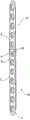
图1是实施例1的整体结构示意图,主要用于体现拼接板的正面结构。FIG. 1 is a schematic diagram of the overall structure of Embodiment 1, which is mainly used to reflect the front structure of the splice board.
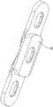
图2是实施例1中用于体现连接结构的爆炸图。FIG. 2 is an exploded view for embodying the connection structure in Embodiment 1. FIG.
图3是图2中A部的放大结构示意图。FIG. 3 is an enlarged schematic view of the structure of part A in FIG. 2 .
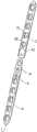
图4是实施例1的整体结构示意图,主要用于体现拼接板的背面结构。FIG. 4 is a schematic diagram of the overall structure of Embodiment 1, which is mainly used to reflect the back structure of the splice board.
图5是用于体现实施例2整体结构的爆炸图。FIG. 5 is an exploded view for embodying the overall structure of
图6是实施例3的整体结构示意图,主要用于体现拼接板的正面结构。FIG. 6 is a schematic diagram of the overall structure of
图7是实施例3的整体结构示意图,主要用于体现拼接板的背面结构。FIG. 7 is a schematic diagram of the overall structure of
图8是用于体现实施例4整体结构的爆炸图。FIG. 8 is an exploded view for embodying the overall structure of
图9是图8中B部的放大结构示意图。FIG. 9 is an enlarged schematic view of the structure of part B in FIG. 8 .
图10是用于体现实施例5整体结构的爆炸图。FIG. 10 is an exploded view for embodying the overall structure of
图11是实施例5中第三拼接板的结构示意图,主要用于体现第三拼接板的背部结构。11 is a schematic structural diagram of the third splice plate in
图12是用于体现实施例6整体结构的爆炸图。FIG. 12 is an exploded view for embodying the overall structure of
图13是用于体现实施例7整体结构的爆炸图。FIG. 13 is an exploded view for embodying the overall structure of
图14是实施例7中第四拼接板的结构示意图,主要用于体现第四拼接板的背部结构。14 is a schematic structural diagram of the fourth splice plate in
图15是用于体现实施例8整体结构的爆炸图。FIG. 15 is an exploded view for embodying the overall structure of
图中,1、第一拼接板;2、第二拼接板;3、LCP结合孔;31、动力加压孔;32、锁定螺孔;4、连接结构;41、第一加压推进板;411、插入部;4111、第一定位孔;412、内圆角过渡面;413、第一推进齿条;42、第二加压推进板;421、插接槽;4211、第二定位孔;422、第二推进齿条;5、去应力槽;6、应力弥散部;7、导向部;71、减压部;8、第三拼接板;9、第四拼接板;10、拼接板。In the figure, 1, the first splice plate; 2, the second splice plate; 3, the LCP combination hole; 31, the dynamic pressure hole; 32, the locking screw hole; 4, the connection structure; 41, the first pressure push plate; 411, insert part; 4111, first positioning hole; 412, inner fillet transition surface; 413, first push rack; 42, second pressurized push plate; 421, insertion slot; 4211, second positioning hole; 422, the second propulsion rack; 5, the stress relief groove; 6, the stress dispersion part; 7, the guide part; 71, the decompression part; 8, the third splice plate; 9, the fourth splice plate;
具体实施方式Detailed ways
以下结合附图对本发明作进一步详细说明。The present invention will be further described in detail below with reference to the accompanying drawings.
实施例1:Example 1:
参照图1,为本实施例公开的一种动态平衡锁定接骨板,包括两块拼接板10,分别为一块第一拼接板1和一块第二拼接板2。第一拼接板1长度方向的端部通过连接结构4拼合于第二拼接板2长度方向的一端,形成的接骨板本体。Referring to FIG. 1 , a dynamic balance locking bone plate disclosed in this embodiment includes two
参照图2,连接结构4包括一体成型于第一拼接板1长度方向一端的第一加压推进板41和一体成型于第二拼接板2长度方向一端的第二加压推进板42。Referring to FIG. 2 , the connecting
参照图3,第一加压推进板41的厚度小于第一拼接板1的厚度,且第一加压推进板41厚度方向一端的端面与第一拼接板1厚度方向一端的端面平齐。第一加压推进板41远离第一拼接板1一端的宽度方向两侧凹陷形成有插入部411,插入部411宽度方向的两个侧边与第一加压推进板41的连接处一体成型有内圆角过渡面412,插入部411宽度方向的两侧通过该内圆角过渡面412与第一加压推进板41形成一体式连接,以分散插入部411与第一加压推进板41连接处的应力。插入部411上沿其厚度方向贯通有腰形的第一定位孔4111。Referring to FIG. 3 , the thickness of the
参照图3,第二加压推进板42的厚度等于第二拼接板2的厚度。第二加压推进板42厚度方向的一侧开设有供插入部411插设插接槽421,插接槽421从其远离第二拼接板2的一端朝向第二拼接板2延伸。插接槽421的深度等于插入部411的厚度,以便插入部411插入插接槽421内时,插接槽421的槽壁不仅能够对插入部411的外周缘形成包裹,且能使第一加压推进板41和第二加压推进板42厚度方向相互远离的端面与第一拼接板1和第二拼接板2厚度方向的两个端面平齐。插接槽421上沿其厚度方向贯通有圆形的第二定位孔4211,第二定位孔4211的孔壁开设内螺纹(图中未示出)。Referring to FIG. 3 , the thickness of the second pressing and pushing
参照图3,两块拼接板10相互加压推进时,第二定位孔4211随第二加压推进板42沿第一定位孔4111的长度方向在第一定位孔4111内移动,以便医务工作者根据断骨所需的加压动力,改变插入部411在插接槽421内的插接深度时,第二定位孔4211的正投影能够位于第一定位孔4111内,使第一定位孔4111和第二定位孔4211内能够共同供螺丝钉穿设固定,从而将第一拼接板1和第二拼接板2与骨骼固定。当第一拼接板1和第二拼接板2与骨骼固定时,第二定位孔4211靠近骨骼设置,且第一定位孔4111的孔径沿靠近第二定位孔的方向呈凹弧形渐缩。共同穿设于第一定位孔4111和第二定位孔4211的螺丝钉的头部靠近该螺丝钉杆部的一侧为直径沿靠近杆部的方向渐缩的半球形,以便螺丝钉的头部靠近杆部的一侧能够抵紧于第二定位孔4211的内壁,从而将相邻两块组合板1固定。Referring to FIG. 3 , when the two
参照图3,插入部411和插接槽412相互抵接的面可以是光滑面,也可以通过喷丸、喷砂、氧化等方法形成粗糙面(图中未示出),其中粗糙面能够增加插入部411和插接槽412之间相互推进时的摩擦阻力,减少加压推进时出现一次加压过大可能性。Referring to FIG. 3 , the abutting surface of the
参照图3,插入部411朝向第二拼接板2的端部为沿接骨板本体的长度方向向外凸出的圆弧形,插接槽421的形状为能够与插入部411的外缘吻合的U形。U形的插接槽421能够分散插接槽421上的应力,使得第二拼接板2不容易从插接槽421处产生疲劳裂纹或发生断裂。同时,端部为圆弧形的设置使得插入部411的端部更为圆滑,在第一拼接板1从插入部411伸入患者软组织内时,能够减少插入部411对患者软组织的剐蹭。Referring to FIG. 3 , the end of the
参照图4,第一拼接板1朝向第二拼接板2的一端为沿第一拼接板1长度方向向外凸出的圆弧形,第二加压推进板42远离第二拼接板2的一端为沿第二拼接板2的长度方向向外凸出的圆弧形,能够对集中于连接结构4处的应力起到分散的效果。同时,端部为圆弧形的第二加压推进板42的设置,在第二拼接板2从第二加压推进板42端伸入患者软组织内时,能够减少第二加压推进板42对患者软组织的剐蹭。Referring to FIG. 4 , one end of the first splicing plate 1 toward the
参照图2,第一拼接板1和第二拼接板2厚度方向远离骨骼的一面均开设有弧形的应力弥散部6,应力弥散部6沿第一拼接板1的长度方向延长。应力弥散部6位于第一拼接板1和第二拼接板2宽度方向的两侧,且位于第一拼接板1和第二拼接板2相互远离的端部的应力弥散部6左右形成连通。Referring to FIG. 2 , arcuate
参照图4,第一拼接板1和第二拼接板2远离连接结构4的端部设置为导向部7,导向部7为沿第一拼接板1或第二拼接板2的长度方向向外凸出的圆弧形,使得导向部7的宽度沿拼接板10的长度方向减缩。导向部7朝向弥散部呈弧形弯折形成减压部71,在第一拼接板1或第二拼接板2插入患者皮下时,导向部7易于逐渐撑开患者软组织,减少接骨板插入时患者的痛苦,同时,患者接骨治疗过程中,减压部71能够减少第一拼接板1和第二拼接板2对患者骨骼的压迫。4 , the ends of the first splicing plate 1 and the
参照图2,第一拼接板1和第二拼接板2上分别沿两者的长度方向开设有多个锁定孔,锁定孔可以为LCP结合孔3,也可以为能够供螺栓穿设从而将两块拼接板10和骨骼固定的任意孔型,本实施例中的锁定孔优选为LCP结合孔3。LCP结合孔3包括内壁无螺纹的动力加压孔31和沿拼接板10长度方向与动力加压孔31连通的锁定螺孔32,锁定螺孔32的内壁开设螺纹(图中未示出),用来连接锁定螺丝钉将拼接板10和骨骼固定,动力加压孔31的孔壁为倾斜的凹弧形,用来偏心连接皮质骨螺丝钉,以实现将拼接板10加压锁定于骨骼上的效果。位于第一拼接板1上的动力加压孔31与位于第二拼接板2上的动力加压孔31相背设置,以便接骨时能够分别从第一拼接板1和第二拼接板2上同时朝向连接结构4的方向向骨折部位加压。Referring to FIG. 2, the first splice plate 1 and the
本实施例的实施原理为:利用本实施例中的拼接式加压锁定接骨板对患者的骨折部位进行接骨时,根据第一拼接板1和第二拼接板2的长度,在患者包绕于断骨外的软组织上做出直至断骨骨膜的切口,将一块拼接板10的导向部7从切口伸入软组织下并经过骨折部位,该块拼接板10达到所需位置后,通过一个LCP结合孔3将其加压锁定于骨骼上。将另一块拼接板10远离导向部7的一端从上述切口伸入,使插入部411插入插接槽421内,从而使得连接结构4形成连接,此时,第二定位孔4211靠近骨骼。根据患者骨折部位所需的复位力推动后伸入的一块拼接板10,改变插入部411在插接槽421内的插入深度,使得后伸入的拼接板10能够带动断骨向正确的复位位置拼合,直至拼接板10施加于断骨上的动力使断骨达到正确的复位位置后,利用螺丝钉从上至下依次穿过第一定位孔4111和第二定位孔4211,对拼接后的第一拼接板1和第二拼接板2同时进行固定。The implementation principle of this embodiment is as follows: when the spliced compression locking bone plate in this embodiment is used to connect the fracture site of the patient, according to the lengths of the first splice plate 1 and the
实施例2:Example 2:
参照图5,本实施例与实施例1的不同之处在于,第一拼接板1上靠近第一加压推进板41设有去应力槽5,去应力槽5沿第一拼接板1的厚度方向贯通第一拼接板1。去应力槽5用于分散集中于连接结构4处的应力,减少接骨板本体固定于骨骼上时从连接结构4处发生断裂的可能性。Referring to FIG. 5 , the difference between this embodiment and Embodiment 1 is that the first splicing plate 1 is provided with a
实施例3:Example 3:
参照图6,本实施例与实施例1的不同之处在于,插入部411朝向第二拼接板2的一端为易于加工的直线形,插接槽421的形状为与插入部411的外缘吻合的方形。Referring to FIG. 6 , the difference between this embodiment and Embodiment 1 is that the end of the
参照图7,第一拼接板1靠近第一加压推进板41的一端和第二加压推进板42远离第二拼接板2的一端均为易于加工的直线形。Referring to FIG. 7 , one end of the first splicing plate 1 close to the first pressing and pushing
实施例4:Example 4:
参照图8和图9,本实施例与实施例1的不同之处在于,插入部411与插接槽421抵接的面设有第一推进齿条413,第一推进齿条413可以设置在插入部411厚度方向与插接槽421的槽底抵接的一面,也可以设置在插入部411宽度方向两侧与插接槽421的侧壁抵接的侧面(图中未示出),还可以同时设置于插入部411与插接槽421抵接的厚度方向的一面和侧面(图中未示出)。第一推进齿条413沿第一拼接板1的长度方向并列设置为若干条,第一推进齿条413朝向靠近其设置的第二加压推进板42的一面向远离与其拼合的第二加压推进板42的方向倾斜。Referring to FIGS. 8 and 9 , the difference between this embodiment and Embodiment 1 is that the surface of the
参照图8和图9,插接槽421内设有若干条与第一推进齿条413啮合的第二推进齿条422,第二推进齿条422可以位于插接槽421的槽底,也可以位于插接槽421宽度方向两侧的内侧壁(图中未示出),还可以同时设置于插接槽421的槽底和宽度方向两侧的槽壁(图中未示出),第二推进齿条422朝向靠近其设置的第一加压推进板41的一面向远离与其拼合的第一加压推进板41的方向倾斜。8 and 9 , the
参照图9,在插入部411插入插接槽421内并逐渐加压推进的过程中,第一推进齿条413和第二推进齿条422易于逐排推进,能够对插入部411的加压动力加以限制,以免出现一次加压过大的情况,便于医务人员根据临床治疗准确选择接骨板的加压动力。第一推进齿条413和第二推进齿条422的高度为0.5毫米,在拆板时,医务人员略微抬高插入部411,即可使第一推进齿条413和第二推进齿条422脱离连接。第一推进齿条413相邻两条之间的间距和第二推进齿条422相邻两条之间的间距均为0.06毫米,使得接骨板加压推进一条齿条时,能够产生一个0.06毫米的加压单位,从而使得本实施例中的拼接式加压锁定接骨板可实现微量加压的效果。Referring to FIG. 9 , in the process of inserting the
实施例5:Example 5:
参照图10,本实施例与实施例1的不同之处在于,包括三块拼接板10,分别为一块第三拼接板8和两块实施例1中的第二拼接板2,第三拼接板8长度方向的两端分别一体成型有实施例1中的第一加压推进板41,且第一加压推进板41和第二加压推进板42沿第三拼接板8的长度方向延长。第一加压推进板41厚度方向一端的端面与第三拼接板8厚度方向一端的端面平齐。两块第一加压推进板41远离第三拼接板8的端部形成有实施例1中的插入部411,第三拼接板8长度方向的两端和与其相邻的第二拼接板2之间形成实施例1中的连接结构4,且两个连接结构4对称设置。当三块拼接板10首尾相互拼合时,能够形成接骨板本体。Referring to FIG. 10 , the difference between this embodiment and Embodiment 1 is that three
参照图11,第三拼接板8朝向与其靠近的第二拼接板2的两个端部均为沿第三拼接板8的长度方向向外凸出的圆弧形,第三拼接板8上沿其长度方向可以开设实施例1中的LCP结合孔3(图中未示出)作为锁定孔,也可以开设能够供螺栓穿设从而将第三拼接板8与骨骼固定的任意孔型作为锁定孔,还可以不开孔,优选地,本实施例中第三拼接板8上位于其中部开设有实施例1中的第一定位孔4111作为锁定孔。Referring to Figure 11, the two ends of the
参照图10,本实施例中插入部411和插接槽412相互抵接的面可以设置为实施例1中的光滑面或粗糙面,也可以设置有实施例4中的第一推进齿条413和第二推进齿条422。Referring to FIG. 10 , in this embodiment, the abutting surface of the
实施例6:Example 6:
参照图12,本实施例与实施例5的不同之处在于,第三拼接板8的中部位于两个连接结构4之间开设有实施例2中的去应力槽5,用来分散集中于第三拼接板8和另外两块拼接板连接处的应力。Referring to FIG. 12 , the difference between this embodiment and
实施例7:Example 7:
参照图13,本实施例与实施例1的不同之处在于,包括三块拼接板10,分别为一块第四拼接板9,一块实施例1中的第一拼接板1及一块实施例1中的第二拼接板2。第四拼接板9朝向与其连接的第二拼接板2的一端一体成型有实施例1中的第一加压推进板41,第一加压推进板41厚度方向一端的端面与第四拼接板9厚度方向一端的端面平齐,第四拼接板9朝向与其连接的第一拼接板1的一端一体成型有实施例1中的第二加压推进板42,且第一加压推进板41和第二加压推进板42均沿第四拼接板9的长度方向延长。Referring to FIG. 13 , the difference between this embodiment and Embodiment 1 is that three
参照图13,第四拼接板9上的第一加压推进板41远离第四拼接板9的端部形成有实施例1中的插入部411,用来与第二拼接板2上的插接槽421插接配合,以形成实施例1中的连接结构4。第四拼接板9上的第二加压推进板42上开设有实施例1中的插接槽421,用来与第一拼接板1上的插入部411插接配合,以形成实施例1中的连接结构4。第一拼接板1、第四拼接板9及第二拼接板2通过上述连接结构4依次拼合形成接骨板本体。Referring to FIG. 13 , the end of the first pressurizing and pushing
参照图14,第四拼接板9朝向第二拼接板2的端部均为沿第四拼接板9的长度方向向外凸出的圆弧形,与第四拼接板9固定的插接槽421靠近与其连接的第一拼接板1的端部为向外凸出的圆弧形。第四拼接板9上沿其长度方向可以开设实施例1中的LCP结合孔3作为锁定孔,也可以开设能够供螺栓穿设从而将第四拼接板9与骨骼固定的任意孔型作为锁定孔,还可以不开孔,优选地,本实施例中第四拼接板9上位于其中部开设有实施例中的第一定位孔4111作为锁定孔。14, the end of the
参照图13,本实施例中插入部411和插接槽412相互抵接的面可以设置为实施例1中的光滑面或粗糙面,也可以设置有实施例4中的第一推进齿条413和第二推进齿条422。Referring to FIG. 13 , in this embodiment, the abutting surface of the
实施例8:Example 8:
参照图15,本实施例与实施例7的不同之处在于,第四拼接板9的中部位于两个连接结构4之间开设有实施例2中的去应力槽5,用来分散集中于四拼接板9上的应力。Referring to FIG. 15 , the difference between this embodiment and
本具体实施方式的实施例均为本发明的较佳实施例,并非依此限制本发明的保护范围,故:凡依本发明的结构、形状、原理所做的等效变化,均应涵盖于本发明的保护范围之内。The embodiments of this specific embodiment are all preferred embodiments of the present invention, and are not intended to limit the protection scope of the present invention. Therefore: all equivalent changes made according to the structure, shape and principle of the present invention should be covered in within the protection scope of the present invention.
Claims (10)
Priority Applications (1)
| Application Number | Priority Date | Filing Date | Title |
|---|---|---|---|
| CN202010418380.6ACN111449742A (en) | 2020-05-18 | 2020-05-18 | Dynamic balance locking bone fracture plate |
Applications Claiming Priority (1)
| Application Number | Priority Date | Filing Date | Title |
|---|---|---|---|
| CN202010418380.6ACN111449742A (en) | 2020-05-18 | 2020-05-18 | Dynamic balance locking bone fracture plate |
Publications (1)
| Publication Number | Publication Date |
|---|---|
| CN111449742Atrue CN111449742A (en) | 2020-07-28 |
Family
ID=71672275
Family Applications (1)
| Application Number | Title | Priority Date | Filing Date |
|---|---|---|---|
| CN202010418380.6APendingCN111449742A (en) | 2020-05-18 | 2020-05-18 | Dynamic balance locking bone fracture plate |
Country Status (1)
| Country | Link |
|---|---|
| CN (1) | CN111449742A (en) |
Cited By (2)
| Publication number | Priority date | Publication date | Assignee | Title |
|---|---|---|---|---|
| CN112773491A (en)* | 2020-09-14 | 2021-05-11 | 江苏强圣医疗科技有限公司 | Bone fracture plate with adjustable size for orthopedics department |
| CN114469299A (en)* | 2020-10-26 | 2022-05-13 | 可成生物科技股份有限公司 | Plate Engagement Kit |
Citations (9)
| Publication number | Priority date | Publication date | Assignee | Title |
|---|---|---|---|---|
| US2486303A (en)* | 1948-04-29 | 1949-10-25 | Harry Herschel Leiter | Surgical appliance for bone fractures |
| US20020183756A1 (en)* | 2001-06-04 | 2002-12-05 | Michelson Gary K. | Dynamic, modular, single-lock anterior cervical plate system, having assembleable and moveable segments, instrumentation, and method for installation thereof |
| CN1523972A (en)* | 2001-04-24 | 2004-08-25 | Fixing device for fixing vertebral parts | |
| WO2006111852A2 (en)* | 2005-04-20 | 2006-10-26 | Dalmatic Lystrup A/S | Fixation of bones after fracture |
| CN103635155A (en)* | 2011-06-17 | 2014-03-12 | 迈阿密设备解决方案有限责任公司 | Modular bone plate and member of such a modular bone plate |
| CN107669322A (en)* | 2017-10-17 | 2018-02-09 | 熊鹰 | A kind of stress type locking and pressurizing bone-knitting device |
| CN208851619U (en)* | 2018-06-11 | 2019-05-14 | 郑州康盛久泰医疗器械股份有限公司 | Growth formula bone plate |
| CN209611282U (en)* | 2018-12-28 | 2019-11-12 | 常州市南翔医疗器械有限公司 | Children's locking bone fracture plate |
| CN212261489U (en)* | 2020-05-18 | 2021-01-01 | 常州大章医疗器械有限公司 | Dynamic balance locking bone fracture plate |
- 2020
- 2020-05-18CNCN202010418380.6Apatent/CN111449742A/enactivePending
Patent Citations (10)
| Publication number | Priority date | Publication date | Assignee | Title |
|---|---|---|---|---|
| US2486303A (en)* | 1948-04-29 | 1949-10-25 | Harry Herschel Leiter | Surgical appliance for bone fractures |
| CN1523972A (en)* | 2001-04-24 | 2004-08-25 | Fixing device for fixing vertebral parts | |
| US20040167521A1 (en)* | 2001-04-24 | 2004-08-26 | Paul De Windt | Fixing device for fixing vertebra parts |
| US20020183756A1 (en)* | 2001-06-04 | 2002-12-05 | Michelson Gary K. | Dynamic, modular, single-lock anterior cervical plate system, having assembleable and moveable segments, instrumentation, and method for installation thereof |
| WO2006111852A2 (en)* | 2005-04-20 | 2006-10-26 | Dalmatic Lystrup A/S | Fixation of bones after fracture |
| CN103635155A (en)* | 2011-06-17 | 2014-03-12 | 迈阿密设备解决方案有限责任公司 | Modular bone plate and member of such a modular bone plate |
| CN107669322A (en)* | 2017-10-17 | 2018-02-09 | 熊鹰 | A kind of stress type locking and pressurizing bone-knitting device |
| CN208851619U (en)* | 2018-06-11 | 2019-05-14 | 郑州康盛久泰医疗器械股份有限公司 | Growth formula bone plate |
| CN209611282U (en)* | 2018-12-28 | 2019-11-12 | 常州市南翔医疗器械有限公司 | Children's locking bone fracture plate |
| CN212261489U (en)* | 2020-05-18 | 2021-01-01 | 常州大章医疗器械有限公司 | Dynamic balance locking bone fracture plate |
Cited By (2)
| Publication number | Priority date | Publication date | Assignee | Title |
|---|---|---|---|---|
| CN112773491A (en)* | 2020-09-14 | 2021-05-11 | 江苏强圣医疗科技有限公司 | Bone fracture plate with adjustable size for orthopedics department |
| CN114469299A (en)* | 2020-10-26 | 2022-05-13 | 可成生物科技股份有限公司 | Plate Engagement Kit |
Similar Documents
| Publication | Publication Date | Title |
|---|---|---|
| US9757172B2 (en) | System and method for minimally invasive clavicle plate application | |
| JP4971195B2 (en) | Plates and screws for fracture treatment | |
| JP5507463B2 (en) | Distal tibial plate fixation device | |
| EP2680772B1 (en) | System with bone screw with multiple thread profiles for far cortical locking and flexible engagement to a bone | |
| CN212213863U (en) | Elastic pressure locking bone fracture plate | |
| US7666212B2 (en) | Renew compression screw | |
| US20040097937A1 (en) | Orthopedic bone plate | |
| EP2140823A1 (en) | Pin assembly for operation | |
| CN111449744A (en) | Bone plate fastener and self-pressurizing minimally invasive locking bone plate system comprising same | |
| CN111449742A (en) | Dynamic balance locking bone fracture plate | |
| CN111544104B (en) | A mortise and tenon structure splicing type fracture reduction and compression internal fixation device | |
| TW201233365A (en) | Medical instrument with modular intramedullary nail | |
| CN109820591B (en) | Fracture reduction guiding fixer based on pelvis minimally invasive surgery | |
| CN212234650U (en) | Composite universal locking bone fracture plate | |
| CN212415873U (en) | Assembled pressurization bone fracture plate | |
| CN212261489U (en) | Dynamic balance locking bone fracture plate | |
| CN111449740A (en) | An elastic compression locking bone plate | |
| CN111449741A (en) | Composite universal locking bone fracture plate | |
| CN103654929A (en) | Intramedullary needle for treating human body clavicle fracture | |
| CN111449743A (en) | An assembled compression bone plate | |
| CN213430492U (en) | Self-pressurization minimally invasive locking bone fracture plate system with bone plate fastener | |
| CN203001093U (en) | Intramedullary needle treating clavicular fracture of human body | |
| CN105476704A (en) | Anterior cervical plate fixation system | |
| CN213217545U (en) | Tibia far-end locking steel plate for pilon fracture | |
| CA2691279C (en) | System and method for minimally invasive clavicle plate application |
Legal Events
| Date | Code | Title | Description |
|---|---|---|---|
| PB01 | Publication | ||
| PB01 | Publication | ||
| SE01 | Entry into force of request for substantive examination | ||
| SE01 | Entry into force of request for substantive examination | ||
| RJ01 | Rejection of invention patent application after publication | ||
| RJ01 | Rejection of invention patent application after publication | Application publication date:20200728 |