CN111448716A - backplane connector - Google Patents
backplane connectorDownload PDFInfo
- Publication number
- CN111448716A CN111448716ACN202080000430.7ACN202080000430ACN111448716ACN 111448716 ACN111448716 ACN 111448716ACN 202080000430 ACN202080000430 ACN 202080000430ACN 111448716 ACN111448716 ACN 111448716A
- Authority
- CN
- China
- Prior art keywords
- plate body
- slot
- side wall
- tongue
- backplane connector
- Prior art date
- Legal status (The legal status is an assumption and is not a legal conclusion. Google has not performed a legal analysis and makes no representation as to the accuracy of the status listed.)
- Granted
Links
Images


Classifications
- H—ELECTRICITY
- H01—ELECTRIC ELEMENTS
- H01R—ELECTRICALLY-CONDUCTIVE CONNECTIONS; STRUCTURAL ASSOCIATIONS OF A PLURALITY OF MUTUALLY-INSULATED ELECTRICAL CONNECTING ELEMENTS; COUPLING DEVICES; CURRENT COLLECTORS
- H01R13/00—Details of coupling devices of the kinds covered by groups H01R12/70 or H01R24/00 - H01R33/00
- H01R13/02—Contact members
- H—ELECTRICITY
- H01—ELECTRIC ELEMENTS
- H01R—ELECTRICALLY-CONDUCTIVE CONNECTIONS; STRUCTURAL ASSOCIATIONS OF A PLURALITY OF MUTUALLY-INSULATED ELECTRICAL CONNECTING ELEMENTS; COUPLING DEVICES; CURRENT COLLECTORS
- H01R12/00—Structural associations of a plurality of mutually-insulated electrical connecting elements, specially adapted for printed circuits, e.g. printed circuit boards [PCB], flat or ribbon cables, or like generally planar structures, e.g. terminal strips, terminal blocks; Coupling devices specially adapted for printed circuits, flat or ribbon cables, or like generally planar structures; Terminals specially adapted for contact with, or insertion into, printed circuits, flat or ribbon cables, or like generally planar structures
- H01R12/70—Coupling devices
- H01R12/71—Coupling devices for rigid printing circuits or like structures
- H—ELECTRICITY
- H01—ELECTRIC ELEMENTS
- H01R—ELECTRICALLY-CONDUCTIVE CONNECTIONS; STRUCTURAL ASSOCIATIONS OF A PLURALITY OF MUTUALLY-INSULATED ELECTRICAL CONNECTING ELEMENTS; COUPLING DEVICES; CURRENT COLLECTORS
- H01R13/00—Details of coupling devices of the kinds covered by groups H01R12/70 or H01R24/00 - H01R33/00
- H01R13/40—Securing contact members in or to a base or case; Insulating of contact members
- H01R13/42—Securing in a demountable manner
- H—ELECTRICITY
- H01—ELECTRIC ELEMENTS
- H01R—ELECTRICALLY-CONDUCTIVE CONNECTIONS; STRUCTURAL ASSOCIATIONS OF A PLURALITY OF MUTUALLY-INSULATED ELECTRICAL CONNECTING ELEMENTS; COUPLING DEVICES; CURRENT COLLECTORS
- H01R13/00—Details of coupling devices of the kinds covered by groups H01R12/70 or H01R24/00 - H01R33/00
- H01R13/46—Bases; Cases
- H01R13/502—Bases; Cases composed of different pieces
Landscapes
- Details Of Connecting Devices For Male And Female Coupling (AREA)
- Coupling Device And Connection With Printed Circuit (AREA)
Abstract
Description
Translated fromChinese技术领域technical field
本申请涉及连接器技术领域,例如涉及一种背板连接器。The present application relates to the technical field of connectors, for example, to a backplane connector.
背景技术Background technique
随着信息技术的高速发展,数据传输速率越来越高。高速连接器正向更高的速率,更高的密度发展。其中,背板连接器作为高速连接器的重要一员,其应用场景不断被拓展,如常规的印制板与印制板连接(背板),印制板与印制板垂直连接(正交背板),印制板或线缆与线缆连接(线背板)……相应这些新应用场景对背板连接器的强度、稳固性与可靠性提出了更加苛刻的要求。With the rapid development of information technology, the data transmission rate is getting higher and higher. High-speed connectors are developing towards higher speeds and higher densities. Among them, the backplane connector is an important member of the high-speed connector, and its application scenarios are constantly being expanded, such as the conventional printed board and printed board connection (backplane), the vertical connection between printed boards and printed boards (orthogonal Backplane), printed board or cable and cable connection (line backplane)... Correspondingly, these new application scenarios put forward more stringent requirements on the strength, stability and reliability of backplane connectors.
相关技术的背板连接器,端子组件为薄片体并列式拼接结构,并在该拼接结构上加装诸如盖板、底板等零件或在此基础上热熔或灌胶实现连接器的稳固。相关技术常采用热熔铆接或灌胶粘接的方式增加背板连接器稳固和可靠性,但热熔工艺不好控制,存在危险性,且需新增设备,效率低,成本高;灌胶工艺较成熟,但也存在效率低,成本高,胶模高温易失效等问题。In the backplane connector of the related art, the terminal assembly is a parallel splicing structure of thin slices, and parts such as a cover plate and a bottom plate are added to the splicing structure, or the connector is stabilized by hot melting or glue pouring. Related technologies often use hot-melt riveting or gluing to increase the stability and reliability of the backplane connector, but the hot-melt process is not easy to control, there is danger, and new equipment is required, with low efficiency and high cost; gluing The process is relatively mature, but there are also problems such as low efficiency, high cost, and easy failure of the plastic mold at high temperature.
发明内容SUMMARY OF THE INVENTION
本申请提供了一种背板连接器,能够增加连接器稳固和可靠性。The present application provides a backplane connector, which can increase the stability and reliability of the connector.
本申请实施例提供一种背板连接器,包括:Embodiments of the present application provide a backplane connector, including:
端子组件,所述端子组件包括呈预设夹角连接的第一面和第二面,所述第一面上设有第一安装块,所述第二面上设有第二安装块;a terminal assembly, the terminal assembly includes a first surface and a second surface connected at a preset angle, the first surface is provided with a first mounting block, and the second surface is provided with a second mounting block;
第一盖板,所述第一盖板包括呈所述预设夹角连接的第一板体和第二板体,所述第一板体上设有第一安装孔,所述第二板体上设有第二安装孔,所述第一安装块与所述第一安装孔插接,所述第二安装块与所述第二安装孔插接;a first cover plate, the first cover plate includes a first plate body and a second plate body connected at the preset angle, the first plate body is provided with a first installation hole, the second plate body The body is provided with a second installation hole, the first installation block is inserted into the first installation hole, and the second installation block is inserted into the second installation hole;
第二盖板,所述第二盖板包括呈预设夹角连接的第三板体和第四板体,所述第三板体和所述第四板体均与所述端子组件卡接,且所述第三板体设置为将所述第一板体压紧于所述第一面上,所述第四板体设置为将所述第二板体压紧于所述第二面上。A second cover plate, the second cover plate includes a third plate body and a fourth plate body connected at a preset angle, and both the third plate body and the fourth plate body are clamped with the terminal assembly , and the third plate body is arranged to press the first plate body to the first surface, and the fourth plate body is arranged to press the second plate body to the second surface superior.
附图说明Description of drawings
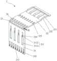
图1为本申请实施例中背板连接器的结构示意图;FIG. 1 is a schematic structural diagram of a backplane connector in an embodiment of the present application;
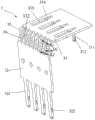
图2为本申请实施例中背板连接器的侧视图;2 is a side view of a backplane connector in an embodiment of the application;
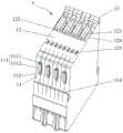
图3为本申请实施例中背板连接器的部分结构示意图(隐藏第二盖板);3 is a schematic diagram of a partial structure of a backplane connector in an embodiment of the present application (the second cover is hidden);
图4为本申请实施例背板连接器中第一盖板的结构示意图;4 is a schematic structural diagram of a first cover plate in a backplane connector according to an embodiment of the present application;
图5为本申请实施例背板连接器中第二盖板的结构示意图;5 is a schematic structural diagram of a second cover plate in the backplane connector according to an embodiment of the present application;
图6为本申请实施例背板连接器中端子组件的结构示意图;6 is a schematic structural diagram of a terminal assembly in a backplane connector according to an embodiment of the present application;
图7为本申请实施例背板连接器中端子组件的剖视图;7 is a cross-sectional view of a terminal assembly in a backplane connector according to an embodiment of the present application;
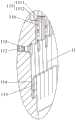
图8为图7中A处的放大示图;Fig. 8 is the enlarged view of the place A in Fig. 7;
图9为图7中B处的放大示图。FIG. 9 is an enlarged view of B in FIG. 7 .
图中:In the picture:
1、端子组件;1. Terminal components;
11、第一面;111、第一安装块;1111、连接部;1112、限位部;112、第一插槽;113、第一卡凸;114、第三插槽;115、第三卡凸;116、第四卡凸;11, the first side; 111, the first installation block; 1111, the connecting part; 1112, the limit part; 112, the first slot; 113, the first card protrusion; 114, the third slot; Convex; 116, the fourth card convex;
12、第二面;121、第二安装块;122、第二插槽;123、第二卡凸;124、凸起;125、第三安装块;126、弧形凸起;12, the second surface; 121, the second installation block; 122, the second slot; 123, the second protrusion; 124, the protrusion; 125, the third installation block; 126, the arc protrusion;
13、端子;13. Terminals;
2、第一盖板;2. The first cover;
21、第一板体;211、第一安装孔;2111、第一孔;2112、第二孔;212、第三插舌;213、第三卡槽;214、第四卡槽;21, the first plate body; 211, the first mounting hole; 2111, the first hole; 2112, the second hole; 212, the third tongue; 213, the third slot; 214, the fourth slot;
22、第二板体;221、第二安装孔;222、弯折凹槽;223、第三安装孔;22, the second plate body; 221, the second installation hole; 222, the bending groove; 223, the third installation hole;
23、第一连接筋;231、第一外侧面;23. The first connecting rib; 231. The first outer side surface;
24、第一插孔;24. The first jack;
3、第二盖板;3. The second cover;
31、第三板体;311、第一插舌;312、第一卡槽;313、第四安装孔;314、冲压孔;31, the third plate body; 311, the first tongue; 312, the first slot; 313, the fourth mounting hole; 314, the punching hole;
32、第四板体;321、第二插舌;322、第二卡槽;32, the fourth plate; 321, the second tongue; 322, the second slot;
33、第二连接筋;331、第二外侧面;332、波谷部;33, the second connecting rib; 331, the second outer side; 332, the trough;
34、第二插孔;34. The second jack;
41、第一曲线;42、第二曲线。41. The first curve; 42. The second curve.
具体实施方式Detailed ways
在本申请的描述中,需要说明的是,术语“中心”、“上”、“下”、“左”、“右”、“竖直”、“水平”、“内”、“外”等指示的方位或位置关系为基于附图所示的方位或位置关系,仅是为了便于描述本申请和简化描述,而不是指示或暗示所指的装置或元件必须具有特定的方位、以特定的方位构造和操作,因此不能理解为对本申请的限制。此外,术语“第一”、“第二”、仅用于描述目的,而不能理解为指示或暗示相对重要性。其中,术语“第一位置”和“第二位置”为两个不同的位置,而且,第一特征在第二特征“之上”、“上方”和“上面”包括第一特征在第二特征正上方和斜上方,或仅仅表示第一特征水平高度高于第二特征。第一特征在第二特征“之下”、“下方”和“下面”包括第一特征在第二特征正下方和斜下方,或仅仅表示第一特征水平高度小于第二特征。In the description of this application, it should be noted that the terms "center", "upper", "lower", "left", "right", "vertical", "horizontal", "inner", "outer", etc. The indicated orientation or positional relationship is based on the orientation or positional relationship shown in the accompanying drawings, which is only for the convenience of describing the present application and simplifying the description, rather than indicating or implying that the indicated device or element must have a specific orientation or a specific orientation. construction and operation, and therefore should not be construed as limitations on this application. Furthermore, the terms "first" and "second" are used for descriptive purposes only and should not be construed to indicate or imply relative importance. Wherein, the terms "first position" and "second position" are two different positions, and the first feature being "above", "over" and "above" the second feature includes the first feature being "over" the second feature Directly above and diagonally above, or simply means that the first feature is level higher than the second feature. The first feature is "below", "below" and "below" the second feature includes the first feature being directly below and diagonally below the second feature, or simply means that the first feature has a lower level than the second feature.
在本申请的描述中,需要说明的是,除非另有明确的规定和限定,术语“安装”、“相连”、“连接”应做广义理解,例如,可以是固定连接,也可以是可拆卸连接,或一体地连接;可以是机械连接,也可以是电连接;可以是直接相连,也可以通过中间媒介间接相连,可以是两个元件内部的连通。对于本领域的普通技术人员而言,可以具体情况理解上述术语在本申请中的具体含义。In the description of this application, it should be noted that, unless otherwise expressly specified and limited, the terms "installed", "connected" and "connected" should be understood in a broad sense, for example, it may be a fixed connection or a detachable connection Connection, or integral connection; can be mechanical connection, can also be electrical connection; can be directly connected, can also be indirectly connected through an intermediate medium, can be internal communication between two elements. For those of ordinary skill in the art, the specific meanings of the above terms in this application can be understood in specific situations.
下面详细描述本申请的实施例,所述实施例的示例在附图中示出,其中自始至终相同或类似的标号表示相同或类似的元件或具有相同或类似功能的元件。下面通过参考附图描述的实施例是示例性的,仅用于解释本申请,而不能理解为对本申请的限制。The following describes in detail the embodiments of the present application, examples of which are illustrated in the accompanying drawings, wherein the same or similar reference numerals refer to the same or similar elements or elements having the same or similar functions throughout. The embodiments described below with reference to the accompanying drawings are exemplary and are only used to explain the present application, but should not be construed as a limitation on the present application.
图1为本申请实施例中背板连接器的结构示意图;图2为本申请实施例中背板连接器的侧视图;图3为本申请实施例中背板连接器的部分结构示意图(隐藏第二盖板3);图4为本申请实施例背板连接器中第一盖板2的结构示意图;图5为本申请实施例背板连接器中第二盖板3的结构示意图;图6为本申请实施例背板连接器中端子组件1的结构示意图;图7为本申请实施例中背板连接器中端子组件1的剖视图;图8为图7中A处的放大示图;图9为图7中B处的放大示图。如图1-图9所示,本实施例提供一种背板连接器,该背板连接器可以为高速连接器,该背板连接器包括端子组件1、第一盖板2和第二盖板3。其中,端子组件1包括呈预设夹角连接的第一面11和第二面12(参考图6),第一面11上设有第一安装块111,第二面12上设有第二安装块121。本实施例中,端子组件1包括多个沿第一方向依次拼接的端子13,第一面11、第二面12、第一安装块111以及第二安装块121均由多个端子13整体拼接形成。1 is a schematic structural diagram of a backplane connector in an embodiment of the application; FIG. 2 is a side view of a backplane connector in an embodiment of the application; The second cover 3); FIG. 4 is a schematic structural diagram of the
如图4所示,第一盖板2包括呈预设夹角连接的第一板体21和第二板体22,第一板体21上设有第一安装孔211,第二板体22上设有第二安装孔221,第一安装块111与第一安装孔211插接,第二安装块121与第二安装孔221插接;通过第一板体21与第一安装块111插接,第二板体22与第二安装块121插接,一方面能够通过第一板体21对端子组件1进行稳固;另一方面,通过第一安装块111和第二安装块121还能够对第一盖板2的两个板体进行限位,以防第一盖板2的两个板体变形。As shown in FIG. 4 , the
如图5所示,第二盖板3包括呈预设夹角连接的第三板体31和第四板体32,第三板体31和第四板体32均与端子组件1卡接,且第三板体31设置为将第一板体21压紧于第一面11上,第四板体32设置为将第二板体22压紧于第二面12上。第二盖板3通过与端子组件1卡接,能够保证第二盖板3与端子组件1的连接稳定,可增强端子组件1整体的稳定性,还可通过端子组件1约束第二盖板3,以防第二盖板3变形。同时,通过第二盖板3将第一盖板2压紧于第一面11和第二面12,则能够防止端子组件1松动,在拔插端子组件1时或端子组件1侧向受力时,可保证端子组件1和对接连接器接触良好,保证信号的完整性。As shown in FIG. 5 , the
本实施例中,预设夹角为90°,于其他的实施例中,预设夹角的大小也可以根据需要进行设置。In this embodiment, the preset included angle is 90°. In other embodiments, the size of the preset included angle can also be set as required.
可选地,第一盖板2和第二盖板3均采用金属材质制成,且均通过冲压工艺成型。从而,第一盖板2和第二盖板3可对端子组件1起到固定的作用。Optionally, both the
可选地,请参照图5、图7和图8,第三板体31上设有第一插舌311,第一面11上设有第一插槽112,第一插舌311的侧壁和第一插槽112的侧壁中的一个上设有第一卡凸113,第一插舌311的侧壁和第一插槽112的侧壁中的另一个上设有第一卡槽312,第一插舌311插接于第一插槽112,且第一卡凸113与第一卡槽312卡接。本实施例中示例性地给出了于第一插槽112的槽壁上设置第一卡凸113,于第一插舌311的侧壁上设置第一卡槽312的方案。在其他的实施例中,也可以在第一插槽112的槽壁上设置第一卡槽312,在第一插舌311的侧壁上设置第一卡凸113。本实施例中,第一插槽112沿垂直于第一面11的方向延伸,且第一插槽112仅于第一面11上设有开口,通过第一插舌311与第一卡槽312插接,并且通过第一卡凸113与第一卡槽312卡接,能够保证第三板体31与第一面11连接稳定,并且第一插槽112的侧壁还可对第一插舌311的位置起到限制作用。Optionally, please refer to FIG. 5 , FIG. 7 and FIG. 8 , the
可选地,请参照图5、图6和图9,第四板体32上设有第二插舌321,第二安装块121上设有第二插槽122,第二插舌321的侧壁和第二插槽122的侧壁中的一个上设有第二卡凸123,第二插舌321的侧壁和第二插槽122的侧壁中的另一个上设有第二卡槽322,第二插舌321插接于第二插槽122,且第二卡凸123与第二卡槽322卡接。本实施例中示例性地给出了于第二插槽122的槽壁上设置第二卡凸123,于第二插舌321的侧壁上设置第二卡槽322的方案。在其他的实施例中,也可以在第二插槽122的槽壁上设置第二卡槽322,在第二插舌321的侧壁上设置第二卡凸123。示例性地,第二安装块121穿过第二安装孔221的部分设置有第二插槽122,本实施例中,第二插槽122设置为通孔,第二插舌321插接于通孔,并与通孔的侧壁卡接,从而,可通过第二卡凸123以及通孔的侧壁对第二插舌321进行限位,能够保证第二插舌321与第二插槽122的连接稳定。如此设置,还可增强第四板体32对第二板体22的压紧效果,保证第二板体22与第二面12贴合。可选地,第二插舌321与第二插槽122的插接方向垂直于第一面11。如此设置,第一插舌311和第二插舌321的插接方向相同便于组装第二盖板3和端子组件1。Optionally, please refer to FIG. 5 , FIG. 6 and FIG. 9 , the
可选地,请参照图1、图2和图6,第一面11上间隔设有多个第一安装块111,第二面12上间隔设有多个第二安装块121,第一板体21上间隔设有多个第一安装孔211,第二板体22上间隔设有多个第二安装孔221,多个第一安装块111与多个第一安装孔211一一对应地插接,多个第二安装块121与多个第二安装孔221一一对应地插接。通过将第一安装块111、第二安装块121均设置为多个,能够保证第一盖板2和端子组件1连接稳定。同理,参考图5和图6,第一面11上间隔设有多个第一插槽112,第二面12上间隔设有多个第二插槽122,第三板体31上间隔设有多个第一插舌311,第四板体32上间隔设有多个第二插舌321,多个第一插舌311与多个第一插槽112一一对应地插接,多个第二插舌321与多个第二插槽122一一对应地插接。通过将第一插舌311、第二插舌321均设置为多个,能够保证第二盖板3和端子组件1连接稳定,并均衡第二盖板3对第一盖板2的压紧力。Optionally, please refer to FIG. 1 , FIG. 2 and FIG. 6 , the
可选地,多个第一安装块111、多个第二安装块121、多个第一插槽112以及多个第二插槽122均由多个端子13拼接而成,多个第一安装块111、多个第二安装块121、多个第一插槽112以及多个第二插槽122均沿第一方向等间距设置。其中,第一方向如图1中的ab方向所示。本实施例中,端子13的数量为偶数个,沿第一方向,依序每两个端子13可形成一个第一安装块111、一个第二安装块121、一个第一插槽112和一个第二插槽122。于其他的实施例中,端子13的数量也可以设置为奇数个。Optionally, the plurality of first installation blocks 111, the plurality of second installation blocks 121, the plurality of
可选地,请参照图4和图6,第二面12上还设有多个凸起124,第二板体22上设有多个弯折凹槽222,多个凸起124与多个弯折凹槽222一一对应地卡接,可选地,相邻的两个第二安装块121之间均设有一个凸起124,从而,可通过凸起124与弯折凹槽222的卡接在垂直于第一面11的方向上保证第二板体22与第二面12连接稳定。Optionally, please refer to FIG. 4 and FIG. 6 , the
可选地,请参照图2、图7和图8,端子组件1上设有第三插槽114,第一板体21上设有第三插舌212,第三插舌212插接于第三插槽114。可选地,第三插舌212的侧壁和第三插槽114的侧壁中的一个上设有第三卡凸115,第三插舌212的侧壁和第三插槽114的侧壁中的另一个上设有第三卡槽213,第三插舌212插接于第三插槽114,且第三卡凸115与第三卡槽213卡接。本实施例中示例性地给出了于第三插槽114的槽壁上设置第三卡凸115,于第三插舌212的侧壁上设置第三卡槽213的方案。在其他的实施例中,也可以在第三插槽114的槽壁上设置第三卡槽213,在第三插舌212的侧壁上设置第三卡凸115。通过使第三插舌212与第三卡槽213插接,并且第三卡凸115与第三卡槽213卡接,能够保证第一板体21与第一面11连接稳定,并可有效防止第一板体21变形。本实施例中,沿第一方向,端子组件1上设有多个第三插槽114,并且第一板体21上对应多个第三插槽114均设有第三插舌212,沿第一方向,依序每两个端子13可形成一个第三插槽114。Optionally, please refer to FIG. 2 , FIG. 7 and FIG. 8 , the
可选地,请参照图3和图4和图6,第二面12上还设有第三安装块125,第二板体22上设有第三安装孔223,第三安装块125设置为过盈插接于第三安装孔223。如此设置,可通过第三安装块125防止第二板体22变形,同时,通过使第三安装块125与第三安装孔223过盈配合,还可保证第二板体22与第二面12连接稳定。本实施例中,第三安装块125的侧壁上间隔设有多个弧形凸起126(参考图9),该弧形凸起126能够过盈地抵接于第三安装孔223。本实施例中,沿第一方向,第二面12上设有多个第三安装块125,并且第二板体22上对应多个第三安装块125均设有第三安装孔223,沿第一方向,依序每两个端子13可形成一个第三安装块125。Optionally, please refer to FIG. 3 , FIG. 4 and FIG. 6 , the
可选地,请参照图6至图8,第一安装块111包括与第一面11连接的连接部1111和与连接部1111连接的限位部1112,连接部1111插接于第一安装孔211,限位部1112和第一面11分别位于第一板体21的两侧,且限位部1112能够与第一板体21在垂直于第一板体21的方向上抵接;第三板体31上设有第四安装孔313,限位部1112插接于第四安装孔313中。通过限位部1112可防止第一板体21与第一面11分离。可选地,如图5所示,第一安装孔211包括连通的第一孔2111和第二孔2112,限位部1112的宽度大于第二孔2112的宽度且小于第一孔2111的宽度,连接部1111的宽度小于第二孔2112的宽度,限位部1112和连接部1111的长度均小于第一孔2111的长度,连接部1111插接于第二孔2112。本实施例中,第一孔2111和第二孔2112于第三插舌212的插接方向上连通,在将第一盖板2和端子组件1组装时,可将限位部1112先从第一孔2111中穿过,并推动第一盖板2,使连接部1111进入至第二孔2112,并与第二孔2112配合,可通过限位部1112对第一板体21在垂直于第一面11的方向上限位,可保证第一板体21与第一面11连接稳定。示例性地,如图5所示,第三板体31上还设有多个第四安装孔313,多个第四安装孔313与多个限位部1112一一对应的插接,如此设置,还可通过限位部1112以防止第三板体31变形,并可增强第三板体31与第一面11连接的稳定性。Optionally, please refer to FIGS. 6 to 8 , the
可选地,请参照4和图8,连接部1111的侧壁和第一安装孔211的第二孔2112的侧壁中的一个上设有第四卡凸116,连接部1111的侧壁和第一安装孔211的第二孔2112的侧壁中的另一个上设有第四卡槽214,第四卡凸116与第四卡槽214卡接。本实施例示例性地给出了于连接部1111的侧壁上设置第四卡凸116,于第二孔2112的侧壁上设置第四卡槽214的方案,如此设置,可保证第一板体21与端子组件1的连接稳定。于其他的实施例中,也可以在连接部1111的侧壁上设置第四卡槽214,于第二孔2112的侧壁上设置第四卡凸116。Optionally, please refer to FIG. 4 and FIG. 8 , one of the side wall of the connecting
可选地,请参照图5,第一插舌311经冲压成型后能够于第三板体31上形成冲压孔314,冲压孔314与第四安装孔313连通。示例性地,第四安装孔313的孔宽大于冲压孔314的孔宽,也就说,在折弯成型出第一插舌311后,再于第三板体31上冲压成型出第四安装孔313,如此设置,能够使第三板体31的结构更加紧凑,在第三板体31长度固定的情况下,可使第一插舌311具备更长的长度,以保证第一插舌311与第一插槽112的有效配合长度,保证第三板体31和第一面11连接稳定。Optionally, please refer to FIG. 5 , after the
可选地,如图4和图5所示,第一盖板2还包括连接第一板体21和第二板体22的多个第一连接筋23,第二盖板3还包括连接第三板体31和第四板体32的多个第二连接筋33,多个第一连接筋23和多个第二连接筋33均沿第一方向间隔设置;任意相邻的两个第一连接筋23之间形成第一插孔24,每个第一插孔24中均插接有一个第二连接筋33。可选地,相邻的两个第二连接筋33之间形成第二插孔34,每个第二插孔34中,均插接有一个第一连接筋23。如此可使第一连接筋23和第二连接筋33交错设置,以保证第一盖板2和第二盖板3于第一方向上的连接稳定性,进而使第一盖板2、第二盖板3以及端子组件1整体保持稳定。Optionally, as shown in FIG. 4 and FIG. 5 , the
可选地,第一连接筋23的外侧面低于第二连接筋33的外侧面或与第二连接筋33的外侧面齐平,其中,请参见图1,不妨将第一连接筋23的外侧面称为第一外侧面231,需要说明的是,第一外侧面231为第一连接筋23远离端子组件1一侧的侧面,不妨将第二连接筋33的外侧面称为第二外侧面331,需要说明的是,第二外侧面331为第二连接筋33远离端子组件1一侧的侧面。Optionally, the outer side surface of the first connecting
本实施例中,第一连接筋23的厚度与第二连接筋33的厚度相等。需要说明的是,第一连接筋23的厚度是指如图4中所示的尺寸D1;第二连接筋33的厚度是指如图5中所示的尺寸D2。In this embodiment, the thickness of the first connecting
在本实施例中,第一连接筋23呈外凸的弧形,第二连接筋33呈波浪形,请参见图5,第二连接筋33具有凹设于第二外侧面331的波谷部332,第二连接筋33的波谷部332插接于第一插孔24。In this embodiment, the first connecting
请参见图1,在本实施例中,任意相邻设置的第一连接筋23和第二连接筋33之间有接触面,该接触面所在平面的法线为沿第一方向设置,该第一连接筋23的第一外侧面231沿第一方向,朝该接触面所在平面的投影为第一曲线41,该第二连接筋33的第二外侧面331沿第一方向,朝该接触面所在平面的投影为第二曲线42,该第一曲线41和该第二曲线42在波谷部332处相切,以使得相邻设置的第一连接筋23和第二连接筋33之间配合更加紧密,且使得第一连接筋23和第二连接筋33在被组装过程中,第一连接筋23和第二连接筋33之间的相对组装位置更容易被确定。Referring to FIG. 1, in this embodiment, there is a contact surface between the first connecting
可选地,第二插孔34靠近第三板体31一侧的宽度不小于第二插孔34靠近第四板体32一侧的宽度。需要说明的是,第二插孔34靠近第三板体31一侧的宽度是指图5中的尺寸R1,第二插孔34靠近第四板体32一侧的宽度是指图5中的尺寸R2。Optionally, the width of the side of the
本实施例提供的背板连接器,包括第一盖板2和第二盖板3以固定端子组件1。其中:第一盖板2的第一板体21与第一面11之间,通过第一安装孔211与第一安装块111插接并且通过第四卡凸116与第四卡槽214卡接;通过第三插舌212与第三插槽114插接并且通过第三卡凸115与第三卡槽213配合实现第三插舌212与端子组件1卡接,可保证第一板体21与第一面11稳定连接。The backplane connector provided in this embodiment includes a
第一盖板2的第二板体22和第二面12之间,通过第二安装块121与第二安装孔221插接;通过凸起124与弯折凹槽222卡接;通过第三安装块125和第三安装孔223过盈插接,可保证第二板体22与第二面12连接稳定。Between the
第二盖板3的第三板体31与第一面11之间,通过第一插舌311与第一插槽112插接且通过第一卡凸113与第一卡槽312卡接;通过第四安装孔313与第一安装块111插接可保证第三板体31与第一面11连接稳定。Between the
第二盖板3的第四板体32与第二面12之间,通过第二插舌321与第二插槽122插接且通过第二卡凸123与第二卡槽322卡接可保证第四板体32与第二面12连接稳定。Between the
第二盖板3和第一盖板2之间通过多个第二连接筋33与多个第一连接筋23交错,可保证第二盖板3和第一盖板2连接稳定。The
当拔插端子组件1时或端子组件1侧向受力时,能够防止端子组件1松动,可保证端子组件1和对接连接器接触良好,保证信号的完整性。并且第一盖板2与第二盖板3配合,无需采用热熔铆接工艺或灌胶粘接工艺,可提升装配效率,提高产能。When the
可选地,每个插舌的端部均设有导向斜面,以便于插舌和对应的插槽插接。Optionally, the end of each insertion tongue is provided with a guide slope, so as to facilitate the insertion of the insertion tongue and the corresponding slot.
本申请提供一种背板连接器,该背板连接器包括端子组件、第一盖板和第二盖板。其中,端子组件包括呈预设夹角连接的第一面和第二面,第一面上设有第一安装块,第二面上设有第二安装块。第一盖板包括呈预设夹角连接的第一板体和第二板体,第一板体上设有第一安装孔,第二板体上设有第二安装孔,第一安装块与第一安装孔插接,第二安装块与第二安装孔插接;通过第一板体与第一安装块插接,第二板体与第二安装块插接,一方面能够通过第一板体对端子组件进行稳固;另一方面,通过第一安装块和第二安装块还能够对第一盖板的两个板体进行限位,以防第一盖板的两个板体变形。第二盖板包括呈预设夹角连接的第三板体和第四板体,第三板体和第四板体均与端子组件卡接,且第三板体将第一板体压紧于第一面,第四板体将第二板体压紧于第二面。第二盖板通过与端子组件卡接卡接,能够保证第二盖板与端子组件的连接稳定,可增强端子组件整体的稳定性,还可通过端子组件以约束第二盖板,以防第二盖板变形,同时,通过第二盖板将第一盖板压紧于第一面和第二面,则能够防止端子组件松动,拔插端子组件时或端子组件侧向受力时,可保证端子组件和对接连接器接触良好,保证信号的完整性。The present application provides a backplane connector, which includes a terminal assembly, a first cover plate and a second cover plate. Wherein, the terminal assembly includes a first surface and a second surface connected at a preset angle, the first surface is provided with a first mounting block, and the second surface is provided with a second mounting block. The first cover plate includes a first plate body and a second plate body connected at a preset angle, the first plate body is provided with a first mounting hole, the second plate body is provided with a second mounting hole, and the first mounting block It is inserted into the first installation hole, and the second installation block is inserted into the second installation hole; the first plate body is inserted into the first installation block, and the second plate body is inserted into the second installation block. A plate body stabilizes the terminal assembly; on the other hand, the first mounting block and the second mounting block can also limit the two plates of the first cover to prevent the two plates of the first cover. deformed. The second cover plate includes a third plate body and a fourth plate body connected at a preset angle, the third plate body and the fourth plate body are both clamped with the terminal assembly, and the third plate body presses the first plate body On the first surface, the fourth plate body presses the second plate body against the second surface. The second cover plate is clamped with the terminal assembly, which can ensure the stable connection between the second cover plate and the terminal assembly, enhance the overall stability of the terminal assembly, and can also restrain the second cover plate through the terminal assembly to prevent the first The second cover plate is deformed, and at the same time, the first cover plate is pressed against the first and second surfaces by the second cover plate, which can prevent the terminal assembly from loosening. Ensure that the terminal assembly and the mating connector are in good contact to ensure the integrity of the signal.
Claims (10)
Applications Claiming Priority (1)
| Application Number | Priority Date | Filing Date | Title |
|---|---|---|---|
| PCT/CN2020/077908WO2021174478A1 (en) | 2020-03-05 | 2020-03-05 | Back plate connector |
Publications (2)
| Publication Number | Publication Date |
|---|---|
| CN111448716Atrue CN111448716A (en) | 2020-07-24 |
| CN111448716B CN111448716B (en) | 2021-09-21 |
Family
ID=71657853
Family Applications (1)
| Application Number | Title | Priority Date | Filing Date |
|---|---|---|---|
| CN202080000430.7AActiveCN111448716B (en) | 2020-03-05 | 2020-03-05 | Back panel connector |
Country Status (2)
| Country | Link |
|---|---|
| CN (1) | CN111448716B (en) |
| WO (1) | WO2021174478A1 (en) |
Citations (11)
| Publication number | Priority date | Publication date | Assignee | Title |
|---|---|---|---|---|
| CA2399960A1 (en)* | 2000-02-03 | 2001-08-09 | Teradyne, Inc. | Connector with shielding |
| CN101330172A (en)* | 2007-06-22 | 2008-12-24 | 贵州航天电器股份有限公司 | High-speed high-density backplane connector with modular structure |
| CN201383572Y (en)* | 2009-03-02 | 2010-01-13 | 莫列斯公司 | Electric connector combination and backboard |
| CN201540983U (en)* | 2008-08-28 | 2010-08-04 | 莫列斯公司 | high-speed connector |
| US20100291806A1 (en)* | 2006-12-19 | 2010-11-18 | Minich Steven E | Shieldless, High-Speed, Low-Cross-Talk Electrical Connector |
| CN102683981A (en)* | 2006-12-19 | 2012-09-19 | Fci公司 | Back panel connector |
| CN204062450U (en)* | 2014-09-17 | 2014-12-31 | 江西华鼎建设工程有限公司 | Steel angle structure body |
| TW201506957A (en)* | 2013-08-07 | 2015-02-16 | Shen Zhen Deren Electronic Co Ltd | HDMI cable, HDMI connector and HDMI interface for high-definition video/audio apparatus |
| CN204289908U (en)* | 2014-10-14 | 2015-04-22 | 富加宜连接器(东莞)有限公司 | A kind of high speed connector optimizing signal integrity |
| CN106252968A (en)* | 2016-07-29 | 2016-12-21 | 中航光电科技股份有限公司 | electrical connector |
| CN109038048A (en)* | 2018-08-14 | 2018-12-18 | 富加宜连接器(东莞)有限公司 | A kind of back panel connector |
Family Cites Families (3)
| Publication number | Priority date | Publication date | Assignee | Title |
|---|---|---|---|---|
| US6641438B1 (en)* | 2002-06-07 | 2003-11-04 | Hon Hai Precision Ind. Co., Ltd. | High speed, high density backplane connector |
| US7261585B2 (en)* | 2005-03-07 | 2007-08-28 | Yazaki Corporation | Press-contact connector |
| CN208753585U (en)* | 2018-09-07 | 2019-04-16 | 富加宜连接器(东莞)有限公司 | A multi-contact backplane connector |
- 2020
- 2020-03-05CNCN202080000430.7Apatent/CN111448716B/enactiveActive
- 2020-03-05WOPCT/CN2020/077908patent/WO2021174478A1/ennot_activeCeased
Patent Citations (11)
| Publication number | Priority date | Publication date | Assignee | Title |
|---|---|---|---|---|
| CA2399960A1 (en)* | 2000-02-03 | 2001-08-09 | Teradyne, Inc. | Connector with shielding |
| US20100291806A1 (en)* | 2006-12-19 | 2010-11-18 | Minich Steven E | Shieldless, High-Speed, Low-Cross-Talk Electrical Connector |
| CN102683981A (en)* | 2006-12-19 | 2012-09-19 | Fci公司 | Back panel connector |
| CN101330172A (en)* | 2007-06-22 | 2008-12-24 | 贵州航天电器股份有限公司 | High-speed high-density backplane connector with modular structure |
| CN201540983U (en)* | 2008-08-28 | 2010-08-04 | 莫列斯公司 | high-speed connector |
| CN201383572Y (en)* | 2009-03-02 | 2010-01-13 | 莫列斯公司 | Electric connector combination and backboard |
| TW201506957A (en)* | 2013-08-07 | 2015-02-16 | Shen Zhen Deren Electronic Co Ltd | HDMI cable, HDMI connector and HDMI interface for high-definition video/audio apparatus |
| CN204062450U (en)* | 2014-09-17 | 2014-12-31 | 江西华鼎建设工程有限公司 | Steel angle structure body |
| CN204289908U (en)* | 2014-10-14 | 2015-04-22 | 富加宜连接器(东莞)有限公司 | A kind of high speed connector optimizing signal integrity |
| CN106252968A (en)* | 2016-07-29 | 2016-12-21 | 中航光电科技股份有限公司 | electrical connector |
| CN109038048A (en)* | 2018-08-14 | 2018-12-18 | 富加宜连接器(东莞)有限公司 | A kind of back panel connector |
Also Published As
| Publication number | Publication date |
|---|---|
| CN111448716B (en) | 2021-09-21 |
| WO2021174478A1 (en) | 2021-09-10 |
Similar Documents
| Publication | Publication Date | Title |
|---|---|---|
| US7273381B2 (en) | Plug connector | |
| CN111403932B (en) | Wire end connector | |
| US6676449B2 (en) | Electrical connector with grounding shell | |
| US20210367362A1 (en) | Electrical connector | |
| US9735486B1 (en) | Electrical connector | |
| JP2002367697A (en) | Contacts and electrical connectors with them | |
| JPWO2019077840A1 (en) | Electrical connector | |
| US20220123503A1 (en) | Electrical connector with flat-type conductor and electrical connector assembly | |
| CN119542792A (en) | Connector components | |
| CN114784533A (en) | An electrical connector and floating connector | |
| CN218498415U (en) | Terminals, Connectors and Connector Assemblies | |
| CN217768830U (en) | Floating type socket connector and electric connector | |
| TW531944B (en) | Board mount type connector and board mounting structure of connector | |
| CN111448716B (en) | Back panel connector | |
| CN110534939B (en) | Connector assembly | |
| CN101197478A (en) | electrical connector with housing | |
| CN118198795A (en) | Small size and high current electrical connector and its matching connector | |
| US10439312B2 (en) | Flat-conductor connector having flat-conductor retaining structure in housing itself | |
| CN212392412U (en) | Board end connector and connector assembly | |
| CN212626166U (en) | Electric connector, butt joint electric connector and electric connector assembly | |
| CN112134051A (en) | Board End Connectors and Connector Assemblies | |
| CN222749793U (en) | Connector | |
| CN112134045B (en) | Electric connector, butt-joint electric connector and electric connector assembly | |
| CN211088582U (en) | Back panel connector | |
| CN211088547U (en) | Back panel connector |
Legal Events
| Date | Code | Title | Description |
|---|---|---|---|
| PB01 | Publication | ||
| PB01 | Publication | ||
| SE01 | Entry into force of request for substantive examination | ||
| SE01 | Entry into force of request for substantive examination | ||
| CB02 | Change of applicant information | Address after:No. 118, Sanjiang Avenue, economic development zone, Mianyang, Sichuan 621000 Applicant after:Sichuan Huafeng Technology Co.,Ltd. Address before:No. 118, Sanjiang Avenue, economic development zone, Mianyang, Sichuan 621000 Applicant before:SICHUAN HUAFENG ENTERPRISE GROUP Co.,Ltd. | |
| CB02 | Change of applicant information | ||
| GR01 | Patent grant | ||
| GR01 | Patent grant |