CN111448646A - Cryogenically cooled rotatable electrostatic chuck - Google Patents
Cryogenically cooled rotatable electrostatic chuckDownload PDFInfo
- Publication number
- CN111448646A CN111448646ACN201880078112.5ACN201880078112ACN111448646ACN 111448646 ACN111448646 ACN 111448646ACN 201880078112 ACN201880078112 ACN 201880078112ACN 111448646 ACN111448646 ACN 111448646A
- Authority
- CN
- China
- Prior art keywords
- coupled
- electrostatic chuck
- backside gas
- supply
- cryogenic
- Prior art date
- Legal status (The legal status is an assumption and is not a legal conclusion. Google has not performed a legal analysis and makes no representation as to the accuracy of the status listed.)
- Granted
Links
- 239000002826coolantSubstances0.000claimsabstractdescription57
- 239000000758substrateSubstances0.000claimsdescription37
- 230000008878couplingEffects0.000claimsdescription36
- 238000010168coupling processMethods0.000claimsdescription36
- 238000005859coupling reactionMethods0.000claimsdescription36
- 238000007789sealingMethods0.000claimsdescription13
- 238000000429assemblyMethods0.000claimsdescription2
- 230000000712assemblyEffects0.000claimsdescription2
- 238000009413insulationMethods0.000claimsdescription2
- 229910001220stainless steelInorganic materials0.000claimsdescription2
- 239000010935stainless steelSubstances0.000claimsdescription2
- 238000001816coolingMethods0.000abstractdescription9
- 239000007789gasSubstances0.000description38
- 238000000034methodMethods0.000description15
- 239000000463materialSubstances0.000description6
- 238000000151depositionMethods0.000description5
- 238000005240physical vapour depositionMethods0.000description5
- 239000012530fluidSubstances0.000description4
- 239000000919ceramicSubstances0.000description3
- 230000008021depositionEffects0.000description3
- 238000005137deposition processMethods0.000description3
- IJGRMHOSHXDMSA-UHFFFAOYSA-NAtomic nitrogenChemical compoundN#NIJGRMHOSHXDMSA-UHFFFAOYSA-N0.000description2
- 229910052782aluminiumInorganic materials0.000description2
- XAGFODPZIPBFFR-UHFFFAOYSA-NaluminiumChemical compound[Al]XAGFODPZIPBFFR-UHFFFAOYSA-N0.000description2
- 238000006243chemical reactionMethods0.000description2
- 238000004891communicationMethods0.000description2
- 150000002500ionsChemical class0.000description2
- 239000007788liquidSubstances0.000description2
- 239000011248coating agentSubstances0.000description1
- 238000000576coating methodMethods0.000description1
- 238000009826distributionMethods0.000description1
- 239000010408filmSubstances0.000description1
- 239000001307heliumSubstances0.000description1
- 229910052734heliumInorganic materials0.000description1
- SWQJXJOGLNCZEY-UHFFFAOYSA-Nhelium atomChemical compound[He]SWQJXJOGLNCZEY-UHFFFAOYSA-N0.000description1
- 238000004519manufacturing processMethods0.000description1
- 229910052751metalInorganic materials0.000description1
- 239000002184metalSubstances0.000description1
- 238000004377microelectronicMethods0.000description1
- 229910052757nitrogenInorganic materials0.000description1
- -1polytetrafluoroethylenePolymers0.000description1
- 229920001343polytetrafluoroethylenePolymers0.000description1
- 239000004810polytetrafluoroethyleneSubstances0.000description1
- 239000003507refrigerantSubstances0.000description1
- 230000000717retained effectEffects0.000description1
- 239000004065semiconductorSubstances0.000description1
- 239000010409thin filmSubstances0.000description1
- 235000012431wafersNutrition0.000description1
Images


Classifications
- C—CHEMISTRY; METALLURGY
- C23—COATING METALLIC MATERIAL; COATING MATERIAL WITH METALLIC MATERIAL; CHEMICAL SURFACE TREATMENT; DIFFUSION TREATMENT OF METALLIC MATERIAL; COATING BY VACUUM EVAPORATION, BY SPUTTERING, BY ION IMPLANTATION OR BY CHEMICAL VAPOUR DEPOSITION, IN GENERAL; INHIBITING CORROSION OF METALLIC MATERIAL OR INCRUSTATION IN GENERAL
- C23C—COATING METALLIC MATERIAL; COATING MATERIAL WITH METALLIC MATERIAL; SURFACE TREATMENT OF METALLIC MATERIAL BY DIFFUSION INTO THE SURFACE, BY CHEMICAL CONVERSION OR SUBSTITUTION; COATING BY VACUUM EVAPORATION, BY SPUTTERING, BY ION IMPLANTATION OR BY CHEMICAL VAPOUR DEPOSITION, IN GENERAL
- C23C14/00—Coating by vacuum evaporation, by sputtering or by ion implantation of the coating forming material
- C23C14/22—Coating by vacuum evaporation, by sputtering or by ion implantation of the coating forming material characterised by the process of coating
- C23C14/50—Substrate holders
- C23C14/505—Substrate holders for rotation of the substrates
- B—PERFORMING OPERATIONS; TRANSPORTING
- B23—MACHINE TOOLS; METAL-WORKING NOT OTHERWISE PROVIDED FOR
- B23Q—DETAILS, COMPONENTS, OR ACCESSORIES FOR MACHINE TOOLS, e.g. ARRANGEMENTS FOR COPYING OR CONTROLLING; MACHINE TOOLS IN GENERAL CHARACTERISED BY THE CONSTRUCTION OF PARTICULAR DETAILS OR COMPONENTS; COMBINATIONS OR ASSOCIATIONS OF METAL-WORKING MACHINES, NOT DIRECTED TO A PARTICULAR RESULT
- B23Q3/00—Devices holding, supporting, or positioning work or tools, of a kind normally removable from the machine
- B23Q3/15—Devices for holding work using magnetic or electric force acting directly on the work
- C—CHEMISTRY; METALLURGY
- C23—COATING METALLIC MATERIAL; COATING MATERIAL WITH METALLIC MATERIAL; CHEMICAL SURFACE TREATMENT; DIFFUSION TREATMENT OF METALLIC MATERIAL; COATING BY VACUUM EVAPORATION, BY SPUTTERING, BY ION IMPLANTATION OR BY CHEMICAL VAPOUR DEPOSITION, IN GENERAL; INHIBITING CORROSION OF METALLIC MATERIAL OR INCRUSTATION IN GENERAL
- C23C—COATING METALLIC MATERIAL; COATING MATERIAL WITH METALLIC MATERIAL; SURFACE TREATMENT OF METALLIC MATERIAL BY DIFFUSION INTO THE SURFACE, BY CHEMICAL CONVERSION OR SUBSTITUTION; COATING BY VACUUM EVAPORATION, BY SPUTTERING, BY ION IMPLANTATION OR BY CHEMICAL VAPOUR DEPOSITION, IN GENERAL
- C23C16/00—Chemical coating by decomposition of gaseous compounds, without leaving reaction products of surface material in the coating, i.e. chemical vapour deposition [CVD] processes
- C23C16/44—Chemical coating by decomposition of gaseous compounds, without leaving reaction products of surface material in the coating, i.e. chemical vapour deposition [CVD] processes characterised by the method of coating
- C23C16/458—Chemical coating by decomposition of gaseous compounds, without leaving reaction products of surface material in the coating, i.e. chemical vapour deposition [CVD] processes characterised by the method of coating characterised by the method used for supporting substrates in the reaction chamber
- C23C16/4582—Rigid and flat substrates, e.g. plates or discs
- C23C16/4583—Rigid and flat substrates, e.g. plates or discs the substrate being supported substantially horizontally
- C23C16/4586—Elements in the interior of the support, e.g. electrodes, heating or cooling devices
- C—CHEMISTRY; METALLURGY
- C23—COATING METALLIC MATERIAL; COATING MATERIAL WITH METALLIC MATERIAL; CHEMICAL SURFACE TREATMENT; DIFFUSION TREATMENT OF METALLIC MATERIAL; COATING BY VACUUM EVAPORATION, BY SPUTTERING, BY ION IMPLANTATION OR BY CHEMICAL VAPOUR DEPOSITION, IN GENERAL; INHIBITING CORROSION OF METALLIC MATERIAL OR INCRUSTATION IN GENERAL
- C23C—COATING METALLIC MATERIAL; COATING MATERIAL WITH METALLIC MATERIAL; SURFACE TREATMENT OF METALLIC MATERIAL BY DIFFUSION INTO THE SURFACE, BY CHEMICAL CONVERSION OR SUBSTITUTION; COATING BY VACUUM EVAPORATION, BY SPUTTERING, BY ION IMPLANTATION OR BY CHEMICAL VAPOUR DEPOSITION, IN GENERAL
- C23C16/00—Chemical coating by decomposition of gaseous compounds, without leaving reaction products of surface material in the coating, i.e. chemical vapour deposition [CVD] processes
- C23C16/44—Chemical coating by decomposition of gaseous compounds, without leaving reaction products of surface material in the coating, i.e. chemical vapour deposition [CVD] processes characterised by the method of coating
- C23C16/46—Chemical coating by decomposition of gaseous compounds, without leaving reaction products of surface material in the coating, i.e. chemical vapour deposition [CVD] processes characterised by the method of coating characterised by the method used for heating the substrate
- C23C16/463—Cooling of the substrate
- H—ELECTRICITY
- H01—ELECTRIC ELEMENTS
- H01J—ELECTRIC DISCHARGE TUBES OR DISCHARGE LAMPS
- H01J37/00—Discharge tubes with provision for introducing objects or material to be exposed to the discharge, e.g. for the purpose of examination or processing thereof
- H01J37/32—Gas-filled discharge tubes
- H01J37/32431—Constructional details of the reactor
- H01J37/32715—Workpiece holder
- H01J37/32724—Temperature
- H—ELECTRICITY
- H01—ELECTRIC ELEMENTS
- H01J—ELECTRIC DISCHARGE TUBES OR DISCHARGE LAMPS
- H01J37/00—Discharge tubes with provision for introducing objects or material to be exposed to the discharge, e.g. for the purpose of examination or processing thereof
- H01J37/32—Gas-filled discharge tubes
- H01J37/34—Gas-filled discharge tubes operating with cathodic sputtering
- H01J37/3411—Constructional aspects of the reactor
- H—ELECTRICITY
- H01—ELECTRIC ELEMENTS
- H01J—ELECTRIC DISCHARGE TUBES OR DISCHARGE LAMPS
- H01J37/00—Discharge tubes with provision for introducing objects or material to be exposed to the discharge, e.g. for the purpose of examination or processing thereof
- H01J37/32—Gas-filled discharge tubes
- H01J37/34—Gas-filled discharge tubes operating with cathodic sputtering
- H01J37/3488—Constructional details of particle beam apparatus not otherwise provided for, e.g. arrangement, mounting, housing, environment; special provisions for cleaning or maintenance of the apparatus
- H—ELECTRICITY
- H01—ELECTRIC ELEMENTS
- H01L—SEMICONDUCTOR DEVICES NOT COVERED BY CLASS H10
- H01L21/00—Processes or apparatus adapted for the manufacture or treatment of semiconductor or solid state devices or of parts thereof
- H01L21/67—Apparatus specially adapted for handling semiconductor or electric solid state devices during manufacture or treatment thereof; Apparatus specially adapted for handling wafers during manufacture or treatment of semiconductor or electric solid state devices or components ; Apparatus not specifically provided for elsewhere
- H01L21/67005—Apparatus not specifically provided for elsewhere
- H01L21/67011—Apparatus for manufacture or treatment
- H01L21/67017—Apparatus for fluid treatment
- H—ELECTRICITY
- H01—ELECTRIC ELEMENTS
- H01L—SEMICONDUCTOR DEVICES NOT COVERED BY CLASS H10
- H01L21/00—Processes or apparatus adapted for the manufacture or treatment of semiconductor or solid state devices or of parts thereof
- H01L21/67—Apparatus specially adapted for handling semiconductor or electric solid state devices during manufacture or treatment thereof; Apparatus specially adapted for handling wafers during manufacture or treatment of semiconductor or electric solid state devices or components ; Apparatus not specifically provided for elsewhere
- H01L21/67005—Apparatus not specifically provided for elsewhere
- H01L21/67011—Apparatus for manufacture or treatment
- H01L21/67098—Apparatus for thermal treatment
- H01L21/67109—Apparatus for thermal treatment mainly by convection
- H—ELECTRICITY
- H01—ELECTRIC ELEMENTS
- H01L—SEMICONDUCTOR DEVICES NOT COVERED BY CLASS H10
- H01L21/00—Processes or apparatus adapted for the manufacture or treatment of semiconductor or solid state devices or of parts thereof
- H01L21/67—Apparatus specially adapted for handling semiconductor or electric solid state devices during manufacture or treatment thereof; Apparatus specially adapted for handling wafers during manufacture or treatment of semiconductor or electric solid state devices or components ; Apparatus not specifically provided for elsewhere
- H01L21/67005—Apparatus not specifically provided for elsewhere
- H01L21/67011—Apparatus for manufacture or treatment
- H01L21/67126—Apparatus for sealing, encapsulating, glassing, decapsulating or the like
- H—ELECTRICITY
- H01—ELECTRIC ELEMENTS
- H01L—SEMICONDUCTOR DEVICES NOT COVERED BY CLASS H10
- H01L21/00—Processes or apparatus adapted for the manufacture or treatment of semiconductor or solid state devices or of parts thereof
- H01L21/67—Apparatus specially adapted for handling semiconductor or electric solid state devices during manufacture or treatment thereof; Apparatus specially adapted for handling wafers during manufacture or treatment of semiconductor or electric solid state devices or components ; Apparatus not specifically provided for elsewhere
- H01L21/683—Apparatus specially adapted for handling semiconductor or electric solid state devices during manufacture or treatment thereof; Apparatus specially adapted for handling wafers during manufacture or treatment of semiconductor or electric solid state devices or components ; Apparatus not specifically provided for elsewhere for supporting or gripping
- H01L21/6831—Apparatus specially adapted for handling semiconductor or electric solid state devices during manufacture or treatment thereof; Apparatus specially adapted for handling wafers during manufacture or treatment of semiconductor or electric solid state devices or components ; Apparatus not specifically provided for elsewhere for supporting or gripping using electrostatic chucks
- H01L21/6833—Details of electrostatic chucks
- H—ELECTRICITY
- H01—ELECTRIC ELEMENTS
- H01L—SEMICONDUCTOR DEVICES NOT COVERED BY CLASS H10
- H01L21/00—Processes or apparatus adapted for the manufacture or treatment of semiconductor or solid state devices or of parts thereof
- H01L21/67—Apparatus specially adapted for handling semiconductor or electric solid state devices during manufacture or treatment thereof; Apparatus specially adapted for handling wafers during manufacture or treatment of semiconductor or electric solid state devices or components ; Apparatus not specifically provided for elsewhere
- H01L21/683—Apparatus specially adapted for handling semiconductor or electric solid state devices during manufacture or treatment thereof; Apparatus specially adapted for handling wafers during manufacture or treatment of semiconductor or electric solid state devices or components ; Apparatus not specifically provided for elsewhere for supporting or gripping
- H01L21/687—Apparatus specially adapted for handling semiconductor or electric solid state devices during manufacture or treatment thereof; Apparatus specially adapted for handling wafers during manufacture or treatment of semiconductor or electric solid state devices or components ; Apparatus not specifically provided for elsewhere for supporting or gripping using mechanical means, e.g. chucks, clamps or pinches
- H01L21/68714—Apparatus specially adapted for handling semiconductor or electric solid state devices during manufacture or treatment thereof; Apparatus specially adapted for handling wafers during manufacture or treatment of semiconductor or electric solid state devices or components ; Apparatus not specifically provided for elsewhere for supporting or gripping using mechanical means, e.g. chucks, clamps or pinches the wafers being placed on a susceptor, stage or support
- H01L21/68742—Apparatus specially adapted for handling semiconductor or electric solid state devices during manufacture or treatment thereof; Apparatus specially adapted for handling wafers during manufacture or treatment of semiconductor or electric solid state devices or components ; Apparatus not specifically provided for elsewhere for supporting or gripping using mechanical means, e.g. chucks, clamps or pinches the wafers being placed on a susceptor, stage or support characterised by a lifting arrangement, e.g. lift pins
- H—ELECTRICITY
- H01—ELECTRIC ELEMENTS
- H01L—SEMICONDUCTOR DEVICES NOT COVERED BY CLASS H10
- H01L21/00—Processes or apparatus adapted for the manufacture or treatment of semiconductor or solid state devices or of parts thereof
- H01L21/67—Apparatus specially adapted for handling semiconductor or electric solid state devices during manufacture or treatment thereof; Apparatus specially adapted for handling wafers during manufacture or treatment of semiconductor or electric solid state devices or components ; Apparatus not specifically provided for elsewhere
- H01L21/683—Apparatus specially adapted for handling semiconductor or electric solid state devices during manufacture or treatment thereof; Apparatus specially adapted for handling wafers during manufacture or treatment of semiconductor or electric solid state devices or components ; Apparatus not specifically provided for elsewhere for supporting or gripping
- H01L21/687—Apparatus specially adapted for handling semiconductor or electric solid state devices during manufacture or treatment thereof; Apparatus specially adapted for handling wafers during manufacture or treatment of semiconductor or electric solid state devices or components ; Apparatus not specifically provided for elsewhere for supporting or gripping using mechanical means, e.g. chucks, clamps or pinches
- H01L21/68714—Apparatus specially adapted for handling semiconductor or electric solid state devices during manufacture or treatment thereof; Apparatus specially adapted for handling wafers during manufacture or treatment of semiconductor or electric solid state devices or components ; Apparatus not specifically provided for elsewhere for supporting or gripping using mechanical means, e.g. chucks, clamps or pinches the wafers being placed on a susceptor, stage or support
- H01L21/68785—Apparatus specially adapted for handling semiconductor or electric solid state devices during manufacture or treatment thereof; Apparatus specially adapted for handling wafers during manufacture or treatment of semiconductor or electric solid state devices or components ; Apparatus not specifically provided for elsewhere for supporting or gripping using mechanical means, e.g. chucks, clamps or pinches the wafers being placed on a susceptor, stage or support characterised by the mechanical construction of the susceptor, stage or support
- H—ELECTRICITY
- H01—ELECTRIC ELEMENTS
- H01L—SEMICONDUCTOR DEVICES NOT COVERED BY CLASS H10
- H01L21/00—Processes or apparatus adapted for the manufacture or treatment of semiconductor or solid state devices or of parts thereof
- H01L21/67—Apparatus specially adapted for handling semiconductor or electric solid state devices during manufacture or treatment thereof; Apparatus specially adapted for handling wafers during manufacture or treatment of semiconductor or electric solid state devices or components ; Apparatus not specifically provided for elsewhere
- H01L21/683—Apparatus specially adapted for handling semiconductor or electric solid state devices during manufacture or treatment thereof; Apparatus specially adapted for handling wafers during manufacture or treatment of semiconductor or electric solid state devices or components ; Apparatus not specifically provided for elsewhere for supporting or gripping
- H01L21/687—Apparatus specially adapted for handling semiconductor or electric solid state devices during manufacture or treatment thereof; Apparatus specially adapted for handling wafers during manufacture or treatment of semiconductor or electric solid state devices or components ; Apparatus not specifically provided for elsewhere for supporting or gripping using mechanical means, e.g. chucks, clamps or pinches
- H01L21/68714—Apparatus specially adapted for handling semiconductor or electric solid state devices during manufacture or treatment thereof; Apparatus specially adapted for handling wafers during manufacture or treatment of semiconductor or electric solid state devices or components ; Apparatus not specifically provided for elsewhere for supporting or gripping using mechanical means, e.g. chucks, clamps or pinches the wafers being placed on a susceptor, stage or support
- H01L21/68792—Apparatus specially adapted for handling semiconductor or electric solid state devices during manufacture or treatment thereof; Apparatus specially adapted for handling wafers during manufacture or treatment of semiconductor or electric solid state devices or components ; Apparatus not specifically provided for elsewhere for supporting or gripping using mechanical means, e.g. chucks, clamps or pinches the wafers being placed on a susceptor, stage or support characterised by the construction of the shaft
- H—ELECTRICITY
- H02—GENERATION; CONVERSION OR DISTRIBUTION OF ELECTRIC POWER
- H02N—ELECTRIC MACHINES NOT OTHERWISE PROVIDED FOR
- H02N13/00—Clutches or holding devices using electrostatic attraction, e.g. using Johnson-Rahbek effect
- H—ELECTRICITY
- H01—ELECTRIC ELEMENTS
- H01L—SEMICONDUCTOR DEVICES NOT COVERED BY CLASS H10
- H01L21/00—Processes or apparatus adapted for the manufacture or treatment of semiconductor or solid state devices or of parts thereof
- H01L21/02—Manufacture or treatment of semiconductor devices or of parts thereof
- H01L21/02104—Forming layers
- H01L21/02107—Forming insulating materials on a substrate
- H01L21/02225—Forming insulating materials on a substrate characterised by the process for the formation of the insulating layer
- H01L21/0226—Forming insulating materials on a substrate characterised by the process for the formation of the insulating layer formation by a deposition process
- H01L21/02263—Forming insulating materials on a substrate characterised by the process for the formation of the insulating layer formation by a deposition process deposition from the gas or vapour phase
- H01L21/02266—Forming insulating materials on a substrate characterised by the process for the formation of the insulating layer formation by a deposition process deposition from the gas or vapour phase deposition by physical ablation of a target, e.g. sputtering, reactive sputtering, physical vapour deposition or pulsed laser deposition
- H—ELECTRICITY
- H01—ELECTRIC ELEMENTS
- H01L—SEMICONDUCTOR DEVICES NOT COVERED BY CLASS H10
- H01L21/00—Processes or apparatus adapted for the manufacture or treatment of semiconductor or solid state devices or of parts thereof
- H01L21/67—Apparatus specially adapted for handling semiconductor or electric solid state devices during manufacture or treatment thereof; Apparatus specially adapted for handling wafers during manufacture or treatment of semiconductor or electric solid state devices or components ; Apparatus not specifically provided for elsewhere
- H01L21/67005—Apparatus not specifically provided for elsewhere
- H01L21/67011—Apparatus for manufacture or treatment
- H01L21/67098—Apparatus for thermal treatment
- H01L21/67103—Apparatus for thermal treatment mainly by conduction
Landscapes
- Engineering & Computer Science (AREA)
- Physics & Mathematics (AREA)
- Chemical & Material Sciences (AREA)
- Condensed Matter Physics & Semiconductors (AREA)
- General Physics & Mathematics (AREA)
- Manufacturing & Machinery (AREA)
- Computer Hardware Design (AREA)
- Microelectronics & Electronic Packaging (AREA)
- Power Engineering (AREA)
- Mechanical Engineering (AREA)
- Analytical Chemistry (AREA)
- Plasma & Fusion (AREA)
- Chemical Kinetics & Catalysis (AREA)
- Materials Engineering (AREA)
- Metallurgy (AREA)
- Organic Chemistry (AREA)
- General Chemical & Material Sciences (AREA)
- Container, Conveyance, Adherence, Positioning, Of Wafer (AREA)
- Physical Vapour Deposition (AREA)
- Jigs For Machine Tools (AREA)
Abstract
Translated fromChinese
Description
Translated fromChinese技术领域technical field
本公开内容的实施方式一般地涉及静电卡盘,该静电卡盘用于在微电子装置制造工艺中保持基板。Embodiments of the present disclosure generally relate to electrostatic chucks for holding substrates in a microelectronic device fabrication process.
背景技术Background technique
在基板上形成某些装置需要多层的薄膜,这些薄膜在诸如物理气相沉积(PVD)腔室的沉积腔室中被沉积。在一些实施方式中,基板需要在沉积处理期间旋转以获得良好的膜均匀性。某些层的沉积亦可能需要将基板冷却。此外,沉积处理需要高真空压力。静电卡盘通常用于在沉积工艺中将基板静电保持在基板支撑件上。常规地,静电卡盘包括陶瓷主体,该陶瓷主体中具有一或多个电极。典型的可旋转静电卡盘仅能够在室温或更高温度下使用。然而,发明人观察到某些工艺要求将基板冷却至显著低于当前静电卡盘可能的温度。Forming certain devices on a substrate requires multiple layers of thin films that are deposited in a deposition chamber such as a physical vapor deposition (PVD) chamber. In some embodiments, the substrate needs to be rotated during the deposition process for good film uniformity. The deposition of certain layers may also require cooling of the substrate. Furthermore, deposition processes require high vacuum pressures. Electrostatic chucks are commonly used to electrostatically hold substrates on substrate supports during deposition processes. Conventionally, electrostatic chucks include a ceramic body having one or more electrodes therein. Typical rotatable electrostatic chucks can only be used at room temperature or higher. However, the inventors have observed that certain processes require cooling the substrate to temperatures significantly lower than what is possible with current electrostatic chucks.
因此,发明人提供了改进的可旋转静电卡盘的实施方式。Accordingly, the inventors provide improved embodiments of rotatable electrostatic chucks.
发明内容SUMMARY OF THE INVENTION
本公开内容的实施方式一般地涉及可旋转静电卡盘。在一些实施方式中,静电卡盘包括介电盘,该介电盘具有用以支撑基板的支撑表面及相对的第二表面,其中至少一个卡紧电极设置在介电盘内的支撑表面与第二表面之间,且其中多个冷却剂通道设置在介电盘内;低温歧管,该低温歧管耦接到介电盘的第二表面并具有冷却剂入口及冷却剂出口,该冷却剂入口及该冷却剂出口两者皆流体耦合到多个冷却剂通道;轴组件,该轴组件在其第一端处耦接到低温歧管,其中该轴组件包括延伸穿过该轴组件的中心开口;低温供应腔室,该低温供应腔室在轴组件相对于第一端的第二端处耦接到该轴组件;供应管,该供应管在其第一端处耦接到低温供应腔室以接收低温介质,并且在该供应管的第二端处耦接到冷却剂入口以将低温介质供应到多个冷却剂通道,其中供应管延伸穿过该中心开口并与轴组件同心(concentric);及回流管,该回流管在其第一端处耦接到冷却剂出口,并且在回流管的第二端处耦接到低温供应腔室,以在低温介质流过多个冷却剂通道之后,使低温介质返回到低温供应腔室,其中回流管延伸穿过该中心开口并与供应管同心,且其中供应管设置在回流管内。Embodiments of the present disclosure generally relate to rotatable electrostatic chucks. In some embodiments, the electrostatic chuck includes a dielectric disk having a support surface for supporting the substrate and an opposing second surface, wherein at least one chucking electrode is disposed within the dielectric disk with the support surface and the first opposing surface. between the two surfaces and wherein a plurality of coolant passages are disposed within the dielectric disk; a cryogenic manifold coupled to the second surface of the dielectric disk and having a coolant inlet and a coolant outlet, the coolant Both the inlet and the coolant outlet are fluidly coupled to a plurality of coolant passages; a shaft assembly coupled to the cryogenic manifold at a first end thereof, wherein the shaft assembly includes a center extending through the shaft assembly an opening; a cryogenic supply chamber coupled to the shaft assembly at its second end relative to the first end; a supply tube coupled to the cryogenic supply chamber at its first end a chamber to receive cryogenic medium and coupled to a coolant inlet at a second end of the supply tube to supply cryogenic medium to a plurality of coolant passages, wherein the supply tube extends through the central opening and is concentric with the shaft assembly ); and a return pipe coupled to a coolant outlet at a first end thereof and to a cryogenic supply chamber at a second end of the return pipe to flow a cryogenic medium through the plurality of coolant passages Afterwards, the cryogenic medium is returned to the cryogenic supply chamber, wherein the return pipe extends through the central opening and is concentric with the supply pipe, and wherein the supply pipe is disposed within the return pipe.
在一些实施方式中,静电卡盘包括介电盘,该介电盘具有用以支撑基板的支撑表面及相对的第二表面,其中至少一个卡紧电极设置在介电盘内的支撑表面与第二表面之间,且其中多个冷却剂通道设置在介电盘内;低温歧管,该低温歧管耦接到介电盘的第二表面并具有冷却剂入口及冷却剂出口,该冷却剂入口及该冷却剂出口两者皆流体耦合到多个冷却剂通道;轴组件,该轴组件在其第一端处耦接到低温歧管,其中该轴组件包括延伸穿过该轴组件的中心开口;低温供应腔室,该低温供应腔室在轴组件相对于第一端的第二端处耦接到该轴组件;真空泵,该真空泵流体耦合到低温供应腔室,以将该低温供应腔室维持在真空压力;供应管,该供应管在其第一端处耦接到低温供应腔室以接收低温介质,并且在该供应管的第二端处耦接到冷却剂入口以将低温介质供应到多个冷却剂通道,其中供应管延伸穿过该中心开口并与轴组件同心;隔热层,该隔热层设置在供应管的外表面上;回流管,该回流管在其第一端处耦接到冷却剂出口并且在该回流管的第二端处耦接到低温供应腔室,以在低温介质流过多个冷却剂通道之后使低温介质返回到低温供应腔室,其中回流管延伸穿过中心开口并与供应管同心,且其中供应管设置在回流管内;滑环,该滑环耦接到轴组件的第二端,以促使来自电源的功率耦合到至少一个卡紧电极;及驱动组件,该驱动组件耦接到轴组件以使轴组件及介电盘旋转。In some embodiments, the electrostatic chuck includes a dielectric disk having a support surface for supporting the substrate and an opposing second surface, wherein at least one chucking electrode is disposed within the dielectric disk with the support surface and the first opposing surface. between the two surfaces and wherein a plurality of coolant passages are disposed within the dielectric disk; a cryogenic manifold coupled to the second surface of the dielectric disk and having a coolant inlet and a coolant outlet, the coolant Both the inlet and the coolant outlet are fluidly coupled to a plurality of coolant passages; a shaft assembly coupled to the cryogenic manifold at a first end thereof, wherein the shaft assembly includes a center extending through the shaft assembly an opening; a cryogenic supply chamber coupled to the shaft assembly at a second end of the shaft assembly relative to the first end; a vacuum pump fluidly coupled to the cryogenic supply chamber for the cryogenic supply chamber the chamber is maintained at vacuum pressure; a supply tube coupled to the cryogenic supply chamber at a first end thereof to receive the cryogenic medium and coupled to a coolant inlet at a second end of the supply tube to supply the cryogenic medium supply to a plurality of coolant passages, wherein a supply tube extends through the central opening and is concentric with the shaft assembly; an insulating layer disposed on the outer surface of the supply tube; and a return tube at its first coupled to the coolant outlet at one end and to the cryogenic supply chamber at a second end of the return tube to return the cryogenic medium to the cryogenic supply chamber after the cryogenic medium has flowed through the plurality of coolant passages, wherein the return flow a tube extending through the central opening and concentric with the supply tube, and wherein the supply tube is disposed within the return tube; a slip ring coupled to the second end of the shaft assembly to facilitate coupling of power from the power source to the at least one clamping electrode ; and a drive assembly coupled to the shaft assembly to rotate the shaft assembly and the dielectric disk.
在一些实施方式中,处理腔室包括腔室主体,该腔室主体具有内部体积;及静电卡盘,该静电卡盘设置在内部体积的下部内。静电卡盘包括介电盘,该介电盘具有用以支撑基板的支撑表面及相对的第二表面,其中至少一个卡紧电极被设置在介电盘内的支撑表面与第二表面之间,且其中多个冷却剂通道被设置在介电盘内;低温歧管,该低温歧管耦接到介电盘的第二表面并具有冷却剂入口及冷却剂出口,该冷却剂入口及该冷却剂出口两者皆流体耦合到多个冷却剂通道;轴组件,该轴组件在其第一端处耦接到低温歧管,其中该轴组件包括延伸穿过该轴组件的中心开口;低温供应腔室,该低温供应腔室在轴组件相对于第一端的第二端处耦接到该轴组件;供应管,该供应管在其第一端处耦接到低温供应腔室以接收低温介质,并且在该供应管的第二端处耦接到冷却剂入口以将低温介质供应到多个冷却剂通道,其中供应管延伸穿过该中心开口并与轴组件同心;及回流管,该回流管在其第一端处耦接到冷却剂出口,并且在回流管的第二端处耦接到低温供应腔室,以在低温介质流过多个冷却剂通道之后,使低温介质返回到低温供应腔室,其中回流管延伸穿过该中心开口并与供应管同心,且其中供应管设置在回流管内。In some embodiments, a processing chamber includes a chamber body having an interior volume; and an electrostatic chuck disposed within a lower portion of the interior volume. The electrostatic chuck includes a dielectric disk having a support surface for supporting a substrate and an opposing second surface, wherein at least one chuck electrode is disposed within the dielectric disk between the support surface and the second surface, and wherein a plurality of coolant passages are provided within the dielectric disk; a cryogenic manifold coupled to the second surface of the dielectric disk and having a coolant inlet and a coolant outlet, the coolant inlet and the cooling a coolant outlet both fluidly coupled to a plurality of coolant passages; a shaft assembly coupled at a first end thereof to the cryogenic manifold, wherein the shaft assembly includes a central opening extending through the shaft assembly; a cryogenic supply a chamber coupled to the shaft assembly at a second end of the shaft assembly relative to the first end; a supply tube coupled to the cryogenic supply chamber at its first end to receive the cryogenic a medium and is coupled to a coolant inlet at a second end of the supply tube to supply cryogenic medium to the plurality of coolant passages, wherein the supply tube extends through the central opening and is concentric with the shaft assembly; and a return tube, the The return tube is coupled to the coolant outlet at a first end thereof and to the cryogenic supply chamber at a second end of the return tube to return the cryogenic medium to the cryogenic medium after flowing through the plurality of coolant passages A cryogenic supply chamber with a return pipe extending through the central opening and concentric with the supply pipe, and wherein the supply pipe is disposed within the return pipe.
以下更详细地描述本公开内容的其他及进一步的实施方式。Other and further embodiments of the present disclosure are described in greater detail below.
附图说明Description of drawings
以上简要概述及在下文更详细讨论的本公开内容的说明性实施方式,可通过参考附图中描绘的本公开内容的实施方式来理解。然而,附图仅绘示了本公开内容的典型实施方式,因此不应视为对本发明的范围的限制,因为本公开内容可允许其他等同有效的实施方式。The illustrative embodiments of the present disclosure, briefly summarized above and discussed in greater detail below, can be understood by reference to the embodiments of the present disclosure depicted in the accompanying drawings. However, the appended drawings depict only typical embodiments of this disclosure and are therefore not to be considered limiting of its scope, for this disclosure may admit to other equally effective embodiments.
图1根据本公开内容的至少一些实施方式描绘适合具有静电卡盘的处理腔室的示意性侧视图。1 depicts a schematic side view of a processing chamber suitable for having an electrostatic chuck in accordance with at least some embodiments of the present disclosure.
图2A根据本公开内容的至少一些实施方式描绘静电卡盘的上部的示意性横截面图。2A depicts a schematic cross-sectional view of an upper portion of an electrostatic chuck in accordance with at least some embodiments of the present disclosure.
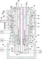
图2B根据本公开内容的至少一些实施方式描绘静电卡盘的下部的示意性横截面图。2B depicts a schematic cross-sectional view of a lower portion of an electrostatic chuck in accordance with at least some embodiments of the present disclosure.
图2C描绘图2B的静电卡盘的一部分的特写示意性横截面图。Figure 2C depicts a close-up schematic cross-sectional view of a portion of the electrostatic chuck of Figure 2B.
为了便于理解,尽可能地使用相同的附图标号来标示图式中共通的相同元件。图式未按比例绘制,且可能为了清楚起见而简化。一个实施方式的元件及特征在没有进一步描述下可有利地并入其他实施方式中。To facilitate understanding, where possible, the same reference numerals have been used to designate the same elements that are common to the drawings. The drawings are not to scale and may be simplified for clarity. Elements and features of one embodiment may be advantageously incorporated into other embodiments without further description.
具体实施方式Detailed ways
本文提供了具有低温冷却功能的可旋转静电卡盘(ESC)的实施方式。创新的静电卡盘对旋转ESC提供低温冷却介质,因此有利地允许旋转ESC用于需要比传统可旋转ESC使用传统冷却方法可能达到的温度更低的温度的工艺。Embodiments of rotatable electrostatic chucks (ESCs) with cryogenic cooling are provided herein. The innovative electrostatic chuck provides a cryogenic cooling medium to the rotating ESC, thus advantageously allowing the rotating ESC to be used in processes requiring lower temperatures than is possible with conventional rotatable ESCs using conventional cooling methods.
图1是根据本公开内容的一些实施方式的处理腔室(例如,等离子体处理腔室)的示意性横截面图。在一些实施方式中,等离子体处理腔室是物理气相沉积(PVD)处理腔室。然而,构造用于不同工艺的其他类型的处理腔室亦可使用本文所述的创新静电卡盘的实施方式或经修改以与之结合使用。1 is a schematic cross-sectional view of a processing chamber (eg, a plasma processing chamber) in accordance with some embodiments of the present disclosure. In some embodiments, the plasma processing chamber is a physical vapor deposition (PVD) processing chamber. However, other types of processing chambers configured for different processes may also use or be modified for use with the embodiments of the innovative electrostatic chuck described herein.
腔室100为真空腔室,其合适地适配以在基板处理期间在腔室内部体积120内维持低于大气压的压力。腔室100包括由盖子104覆盖的腔室主体106,盖子104包围位于腔室内部体积120的上半部分中的处理体积119。腔室100亦可包括一或多个护罩105,该护罩围绕各种腔室部件,以防止此类部件与离子化的处理材料之间产生不期望的反应。腔室主体106及盖子104可由诸如铝的金属制成。腔室主体106可经由对地115的耦接而接地。
基板支撑件124设置在腔室内部体积120内,以支撑及保持基板S,例如半导体晶片,或可静电保持其他此类基板。基板支撑件124通常可包括静电卡盘150(下方参考图2A至图2B更详细地描述)及用于支撑静电卡盘150的中空支撑轴112。中空支撑轴112提供导管以向静电卡盘150提供,例如,提供处理气体、流体、冷却剂、功率或类似物。
在一些实施方式中,中空支撑轴112耦接到升降机构113,例如致动器或马达,该升降机构提供静电卡盘150在上部处理位置(如图1所示)与下部转移位置(未图出)之间的垂直运动。波纹管组件110围绕中空支撑轴112设置,并且耦接在静电卡盘150与腔室100的底表面126之间,以提供弹性密封,该弹性密封允许静电卡盘150的垂直运动并同时防止腔室100内失去真空。波纹管组件110亦包括下波纹管凸缘164,该下波纹管凸缘与O形环165或其他合适的密封元件接触,该密封元件与底表面126接触,以帮助防止失去腔室真空。In some embodiments, the
中空支撑轴112提供导管,该导管用于将流体源142、气源141、卡紧电源140及RF源(例如,RF等离子体电源170及RF偏压电源117)耦接到静电卡盘150。在一些实施方式中,RF等离子体电源170及RF偏压电源117经由相应的RF匹配网络(仅图示RF匹配网络116)耦接到静电卡盘。在一些实施方式中,基板支撑件可替代地包括AC、DC或RF偏压功率。
基板升降器130可包括升降销109,这些升降销安装在平台108上,该平台耦接到轴111,该轴耦接到第二升降机构132,以用于升高及降低基板升降器130,使得基板“S”可放置在静电卡盘150上或从该静电卡盘移除。静电卡盘150包括用以接收升降销109的通孔。波纹管组件131耦接在基板升降器130与底表面126之间以提供弹性密封,该弹性密封在基板升降器130的垂直运动期间保持腔室真空。The
腔室100耦接到真空系统114并与该真空系统流体连通,该真空系统包括用以使腔室100排气的节流阀(未示出)及真空泵(未示出)。可通过调整节流阀和/或真空泵来调节腔室100内的压力。腔室100亦耦接到处理气体源118并与该处理气体源流体连通,该处理气体源可将一或多种处理气体供应到腔室100,以用于处理设置在其中的基板。The
在操作中,例如,可在腔室内部体积120中产生等离子体102以执行一或多个工艺。可通过经由一或多个电极将来自等离子体电源(例如,RF等离子体电源170)的功率耦合到处理气体来产生等离子体102,所述一或多个电极靠近腔室内部体积120或在该腔室内部体积内,以点燃处理气体并产生等离子体102。在一些实施方式中,亦可经由电容耦合的偏压板(下方描述)从偏压电源(例如,RF偏压电源117)提供偏压功率给设置在静电卡盘150内的一或多个电极(下方描述),用以从等离子体吸引离子朝向基板S。In operation, for example,
在一些实施方式中,例如在腔室100是PVD腔室的情况下,靶材166可设置在基板上方且在腔室内部体积120内,该靶材包括待沉积在基板S上的来源材料。靶材166可由腔室100的接地导电部分支撑,例如穿过介电隔离器的铝制适配器。在其他实施方式中,腔室100可包括多阴极布置中的多个靶材,以用于使用相同的腔室沉积不同的材料层。In some embodiments, such as where the
可控制的DC电源168可耦接到腔室100,以对靶材166施加负电压或偏压。RF偏压电源117可耦接到基板支撑件124,以致在基板S上引发负DC偏压。另外,在一些实施方式中,在处理期间可在基板S上形成负DC自偏压。在一些实施方式中,RF等离子体电源170亦可耦接到腔室100以将RF功率施加到靶材166,以促进基板S上的沉积速率的径向分布的控制。在操作中,在腔室100中产生的等离子体102中的离子与来自靶材166的来源材料反应。该反应使得靶材166发射来源材料的原子,接着该原子被导向基板S,从而沉积材料。A controllable
将参考图2A至图2C进行以下描述。图2A根据本公开内容的至少一些实施方式描绘静电卡盘200的上部的示意性横截面图。图2B根据本公开内容的至少一些实施方式描绘静电卡盘200的下部的示意性横截面图。图2C描绘图2B的静电卡盘的一部分的特写示意性横截面图。静电卡盘200包括介电盘202,该介电盘具有支撑表面204以支撑基板、相对的第二表面206,及至少一个卡紧电极208,该卡紧电极设置在介电盘202内的支撑表面204与第二表面206之间。介电盘202进一步包括多个冷却剂通道210,这些冷却剂通道亦设置在介电盘202内的支撑表面204与第二表面206之间。多个冷却剂通道210可形成在介电盘202中,或可包括非渗透性管线以防止低温介质的泄漏。如图2A所示,静电卡盘200的上部设置在壳体221内,该壳体具有类似碟形的形状。壳体221亦包括处理流程中必要的额外特征,例如,壳体升降销孔223(图2A中示出一个),这些壳体升降销孔与相应的盘升降销孔225对准,以允许相应的升降销240(图2A中图示一个)从支撑表面204穿过并使基板升高离开该支撑表面。The following description will be made with reference to FIGS. 2A to 2C . 2A depicts a schematic cross-sectional view of an upper portion of an
在一些实施方式中,低温歧管212耦接到介电盘202的第二表面206。低温歧管212包括冷却剂入口214及冷却剂出口216,该冷却剂入口及该冷却剂出口两者皆流体耦合到多个冷却剂通道210。轴组件218在轴组件218的第一端220处耦接到低温歧管212。轴组件218包括延伸穿过轴组件218的中心开口222,该低温介质供应管/回流管(下方论述)延伸穿过该中心开口。轴组件218包括轴224及挠曲耦接件(flexure coupling)226。轴224及挠曲耦接件226分别包括第一中央通道228及第二中央通道230,这样一起形成中心开口222。挠曲耦接件226经构造以在静电卡盘200的旋转期间将介电盘202保持实质水平。In some embodiments, the cryogenic manifold 212 is coupled to the second surface 206 of the
驱动组件227耦接到轴组件218,以使轴组件218及介电盘202旋转。滑环232(下方论述)耦接到轴224的第一端234,以促使来自电源236的功率耦合到静电卡盘200的各种部件,该静电卡盘诸如,举例而言,一或多个卡紧电极208、一或多个热电偶241等。在一些实施方式中,一或多个功率耦合件243(第一功率耦合件)可延伸穿过会转动的滑环232的一部分,并进入到轴224的底部。功率耦合件243电性耦合到第二功率耦合件245,该第二功率耦合件延伸穿过挠曲耦接件226的下部并进入轴224的上部。挠曲耦接件226耦接到与滑环232相对的轴224的第二端242。在一些实施方式中,轴承组件233绕着挠曲耦接件226设置,以对静电卡盘200的上部提供额外的支撑/刚性,尤其是在旋转期间。The
低温供应腔室244在与轴组件218第一端220相对的第二端247处耦接到轴组件218,以将低温介质供应到介电盘202。由低温供应腔室244供应到介电盘202的低温介质在约5开尔文(Kelvin)与约293开尔文之间。在一些实施方式中,低温介质可为液态氮、液态氦混合制冷剂气体,或类似物。A
为了促使将低温介质从低温供应腔室244输送到介电盘202,供应管246在供应管246的第一端248处耦接到低温供应腔室244并且在供应管246的第二端250处耦接到低温歧管212的冷却剂入口214,以将低温介质供应到多个冷却剂通道210。在一些实施方式中,供应管246延伸穿过中心开口222并与轴组件218同心。To facilitate delivery of cryogenic medium from
为了在低温介质流过多个冷却剂通道210之后促使低温介质返回低温供应腔室244,回流管252在回流管252的第一端254处耦接到低温歧管212的冷却剂出口216,且在回流管252的第二端256处耦接到低温供应腔室244。在一些实施方式中,且如图2A、图2B所示,回流管252延伸穿过中心开口222并且设置在供应管246内并与该供应管同心。在一些实施方式中,为了最小化或实质上防止流过供应管246的低温介质与流过回流管252的使用过的低温介质之间进行热传递,如图2C所示的隔热层258可设置在供应管246的外表面上。在一些实施方式中,隔热层258可为涂层,例如聚四氟乙烯(polytetrafluoroethylene)、陶瓷,或类似物。在一些实施方式中,隔热层258可替代地为陶瓷管,其中供应管246插入该陶瓷管中。To facilitate the return of the cryogenic medium to the
低温供应腔室244包括限定内部体积262的腔室主体260。耦接到冷却器266以用于低温介质的供应及返回的馈通块264设置在内部体积262内。馈通块264包括馈通入口268及馈通出口270,该馈通入口流体耦合到供应管246,且该馈通出口流体耦合到回流管252。由于流过馈通块264的低温介质处于如此低温,故在馈通块264上可能积聚冰或霜。为了避免此种冰积聚,真空泵272经由形成在腔室主体260中的真空端口274流体耦合到内部体积262,以将内部体积262保持在真空压力。在一些实施方式中,真空泵272是粗抽泵(roughingpump),该粗抽泵经构造以将内部体积中的压力保持在大约粗略的真空压力下。在供应管246及回流管252旋转的同时,馈通块264保持静止。The
在一些实施方式中,静电卡盘200可进一步包括密封管276,密封管276耦接到回流管252的下部并且与回流管252同心。密封管276经构造以将处于粗略真空压力的低温供应腔室244的有效体积从处于处理压力的处理体积(例如,处理体积119)密封。为了实现此种密封,密封管276包括天花板部278及开口底端280,该天花板部耦接到回流管252的下部。在一些实施方式中,天花板部278焊接到回流管252。回流管252延伸穿过密封管276的一部分并终止于密封管276内的一点。在一些实施方式中,环形密封件261可围绕密封管276的底部设置,以使环形密封件261下方的粗略真空环境与环形密封件261上方的处理真空环境隔离。In some embodiments, the
在一些实施方式中,波纹管282耦接到回流管252的最下表面284并且设置在密封管276内。波纹管282将回流管252流体耦合到馈通出口270。波纹管282经构造以补偿回流管252的热膨胀、回流管252相对于供应管246的任何错位,以及由静电卡盘200的旋转引起的惯性所导致的任何松弛。在一些实施方式中,波纹管282由不锈钢形成。In some embodiments, the
为了促使冷却传递到设置在介电盘202上方的基板,静电卡盘200进一步包括背侧气体输送系统286,该背侧气体输送系统流体耦合到介电盘202,以将背侧气体供应到多个背侧气体出口288,这些背侧气体出口通过支撑表面204而形成,该支撑表面靠近介电盘202的周边。在一些实施方式中,背侧气体输送系统286包括旋转馈通件290,该旋转馈通件绕着轴224设置并与轴224同心;背侧气体导管292,该背侧气体导管耦接到轴224的第二端242;及背侧气体歧管294,该背侧气体歧管耦接到与轴224相对的背侧气体导管292。旋转馈通件290包括静止的壳体251及圆柱形部分253,该圆柱形部分设置在该壳体内并且可旋转。两个环形轴承组件255、257设置在壳体251与圆柱形部分253之间。旋转馈通件290进一步包括背侧气体耦合件296,以促使背侧气体源耦接到旋转馈通件290。背侧气体歧管294设置在低温歧管212与挠曲耦接件226之间,并且包括歧管通道298,该歧管通道与相应的导管299一起将背侧气体导管292流体耦合到介电盘202中的背侧气体入口203,该相应的导管形成在低温歧管212中并与歧管通道298对准。轴224包括背侧气体通道265,以将背侧气体耦合件296流体耦合到背侧气体导管292。To facilitate cooling transfer to the substrate disposed over the
在一些实施方式中,轴224包括形成在轴224的外表面231中的环形凹部229,且该环形凹部邻近背侧气体耦合件296而设置。背侧气体通道265将环形凹部229流体耦合至背侧气体导管292,使得来自背侧气体耦合件296的背侧气体流动进入环形凹部229,穿过轴224的背侧气体通道265,穿过背侧气体导管292,穿过背侧气体入口203,并穿过多个背侧气体出口288。为了防止背侧气体泄漏,设置在背侧气体耦合件296上方的第一环形密封件239及设置在背侧气体耦合件296下方的第二环形密封件249两者都设置在壳体251与圆柱形部分253之间。在一些实施方式中,第一环形密封元件239及第二环形密封元件249是铁磁流体(ferrofluidic)密封件。另外,第三环形密封元件235绕着轴224设置在背侧气体耦合件296上方,且第四环形密封元件237绕着轴224设置在背侧气体耦合件296下方,以使位于第三环形密封元件235及第四环形密封元件237下方的粗略真空压力环境与第三环形密封元件235及第四环形密封元件237上方的处理真空压力环境流体地隔离。In some embodiments, the
为了控制设置在介电盘202上方的基板的冷却速率,对背侧气体的流速及由卡紧电极提供的夹持力进行控制,以达成基板下方的所需压力及产生期望的冷却速率的基板夹持。一或多个热电偶241可监测介电盘202的温度。对多个冷却剂通道210的低温介质供应及背侧气体的流速是基于由热电偶241提供的温度读数来控制。In order to control the cooling rate of the substrate disposed above the
尽管前述内容针对本公开内容的实施方式,但可在不背离本公开内容的基本范围的情况下设计出本公开内容的其他及进一步实施方式。While the foregoing has been directed to embodiments of the present disclosure, other and further embodiments of the present disclosure can be devised without departing from the essential scope of the present disclosure.
Claims (15)
Applications Claiming Priority (3)
| Application Number | Priority Date | Filing Date | Title |
|---|---|---|---|
| US15/838,314 | 2017-12-11 | ||
| US15/838,314US11149345B2 (en) | 2017-12-11 | 2017-12-11 | Cryogenically cooled rotatable electrostatic chuck |
| PCT/US2018/064674WO2019118320A1 (en) | 2017-12-11 | 2018-12-10 | Cryogenically cooled rotatable electrostatic chuck |
Publications (2)
| Publication Number | Publication Date |
|---|---|
| CN111448646Atrue CN111448646A (en) | 2020-07-24 |
| CN111448646B CN111448646B (en) | 2025-01-03 |
Family
ID=66697307
Family Applications (1)
| Application Number | Title | Priority Date | Filing Date |
|---|---|---|---|
| CN201880078112.5AActiveCN111448646B (en) | 2017-12-11 | 2018-12-10 | Cryogenically cooled rotatable electrostatic chuck |
Country Status (7)
| Country | Link |
|---|---|
| US (1) | US11149345B2 (en) |
| EP (1) | EP3724914A4 (en) |
| JP (1) | JP7317013B2 (en) |
| KR (1) | KR102667399B1 (en) |
| CN (1) | CN111448646B (en) |
| TW (1) | TWI804537B (en) |
| WO (1) | WO2019118320A1 (en) |
Cited By (6)
| Publication number | Priority date | Publication date | Assignee | Title |
|---|---|---|---|---|
| CN112210767A (en)* | 2020-08-31 | 2021-01-12 | 广东鼎泰机器人科技有限公司 | Coating machine |
| CN112251732A (en)* | 2020-08-31 | 2021-01-22 | 广东鼎泰机器人科技有限公司 | Material carrying device of coating machine |
| CN114551203A (en)* | 2020-11-25 | 2022-05-27 | 李喜张 | Linear motion sealing device and semiconductor substrate processing apparatus using the same |
| WO2023202117A1 (en)* | 2022-04-20 | 2023-10-26 | 江苏鲁汶仪器股份有限公司 | Magnetic fluid shaft |
| CN117043388A (en)* | 2021-04-02 | 2023-11-10 | 应用材料公司 | Spin bias susceptor and electrostatic chuck in semiconductor processing chamber |
| WO2024233288A1 (en)* | 2023-05-05 | 2024-11-14 | Lam Research Corporation | Pedestal stem cooling system |
Families Citing this family (17)
| Publication number | Priority date | Publication date | Assignee | Title |
|---|---|---|---|---|
| US10704142B2 (en)* | 2017-07-27 | 2020-07-07 | Applied Materials, Inc. | Quick disconnect resistance temperature detector assembly for rotating pedestal |
| WO2021025913A1 (en) | 2019-08-02 | 2021-02-11 | Applied Materials, Inc. | Radio frequency power return path |
| US11302536B2 (en)* | 2019-10-18 | 2022-04-12 | Applied Materials, Inc. | Deflectable platens and associated methods |
| US10971327B1 (en)* | 2019-12-06 | 2021-04-06 | Applied Materials, Inc. | Cryogenic heat transfer system |
| CN211957594U (en)* | 2020-05-29 | 2020-11-17 | 北京鲁汶半导体科技有限公司 | Ion beam etching rotary platform |
| CN111850501B (en)* | 2020-07-20 | 2022-09-27 | 江苏集萃有机光电技术研究所有限公司 | Substrate frame structure and vacuum evaporation device |
| US11501957B2 (en)* | 2020-09-03 | 2022-11-15 | Applied Materials, Inc. | Pedestal support design for precise chamber matching and process control |
| WO2022048241A1 (en)* | 2020-09-07 | 2022-03-10 | 江苏鲁汶仪器有限公司 | Ion beam etching machine and lifting and rotating platform device thereof |
| CN112760609B (en)* | 2020-12-22 | 2022-10-21 | 北京北方华创微电子装备有限公司 | Magnetron sputtering device |
| JP7736409B2 (en)* | 2021-03-23 | 2025-09-09 | 東京エレクトロン株式会社 | Substrate support unit and substrate processing apparatus |
| US12002668B2 (en)* | 2021-06-25 | 2024-06-04 | Applied Materials, Inc. | Thermal management hardware for uniform temperature control for enhanced bake-out for cluster tool |
| EP4376235A3 (en) | 2021-11-30 | 2024-09-04 | Kern Technologies, LLC | Radio frequency slab laser |
| US20240018646A1 (en)* | 2022-07-14 | 2024-01-18 | Applied Materials, Inc. | Rotary electrical feedthrough integration for process chamber |
| JP2024056426A (en)* | 2022-10-11 | 2024-04-23 | 東京エレクトロン株式会社 | Mounting table and substrate processing apparatus |
| KR102650161B1 (en) | 2023-01-05 | 2024-03-22 | 주식회사 미코세라믹스 | Ceramic susceptor |
| US20250273497A1 (en)* | 2024-02-23 | 2025-08-28 | Applied Materials, Inc. | Cathode assembly for integration of embedded electrostatic chuck (esc) |
| US20250293009A1 (en)* | 2024-03-13 | 2025-09-18 | Applied Materials, Inc. | Advanced thermal management system (atm) for pedestal temperature control in high power pecvd chamber |
Citations (10)
| Publication number | Priority date | Publication date | Assignee | Title |
|---|---|---|---|---|
| US6081414A (en)* | 1998-05-01 | 2000-06-27 | Applied Materials, Inc. | Apparatus for improved biasing and retaining of a workpiece in a workpiece processing system |
| CN101192557A (en)* | 2006-11-30 | 2008-06-04 | 佳能安内华股份有限公司 | Power supply device and deposition method using power supply device |
| CN102160167A (en)* | 2008-08-12 | 2011-08-17 | 应用材料股份有限公司 | Electrostatic chuck assembly |
| US20120033340A1 (en)* | 2010-08-06 | 2012-02-09 | Applied Materials, Inc. | Electrostatic chuck and methods of use thereof |
| US20130088809A1 (en)* | 2011-09-30 | 2013-04-11 | Applied Materials, Inc. | Electrostatic chuck with temperature control |
| JP2013098277A (en)* | 2011-10-31 | 2013-05-20 | Canon Anelva Corp | Substrate holder and vacuum processing apparatus |
| US20150170952A1 (en)* | 2013-12-18 | 2015-06-18 | Applied Materials, Inc. | Rotatable heated electrostatic chuck |
| CN105027274A (en)* | 2013-03-15 | 2015-11-04 | 应用材料公司 | Substrate Support Chuck Cooling for Deposition Chambers |
| CN105580128A (en)* | 2013-09-26 | 2016-05-11 | 应用材料公司 | Rotatable substrate support with RF applicator |
| WO2016148327A1 (en)* | 2015-03-13 | 2016-09-22 | (주)씨앤아이테크놀로지 | In-line sputtering system having plurality of rotatable tray holders, and package shielding manufacturing method using same |
Family Cites Families (18)
| Publication number | Priority date | Publication date | Assignee | Title |
|---|---|---|---|---|
| JP3453223B2 (en)* | 1994-08-19 | 2003-10-06 | 東京エレクトロン株式会社 | Processing equipment |
| US6439244B1 (en) | 2000-10-13 | 2002-08-27 | Promos Technologies, Inc. | Pedestal design for a sputter clean chamber to improve aluminum gap filling ability |
| US6689221B2 (en)* | 2000-12-04 | 2004-02-10 | Applied Materials, Inc. | Cooling gas delivery system for a rotatable semiconductor substrate support assembly |
| EP1833078B1 (en)* | 2004-07-09 | 2013-03-20 | Sekisui Chemical Co., Ltd. | Apparatus and method for processing the outer periphery of a substrate |
| US7429718B2 (en)* | 2005-08-02 | 2008-09-30 | Applied Materials, Inc. | Heating and cooling of substrate support |
| US7589950B2 (en)* | 2006-10-13 | 2009-09-15 | Applied Materials, Inc. | Detachable electrostatic chuck having sealing assembly |
| JP2010267926A (en)* | 2009-05-18 | 2010-11-25 | Nikon Corp | Substrate processing apparatus and device manufacturing method |
| KR101536257B1 (en) | 2009-07-22 | 2015-07-13 | 한국에이에스엠지니텍 주식회사 | Horizontal flow deposition apparatus and deposition method using same |
| JP2012099298A (en)* | 2010-11-01 | 2012-05-24 | Nissin Ion Equipment Co Ltd | Ion implanter |
| US9673037B2 (en)* | 2011-05-31 | 2017-06-06 | Law Research Corporation | Substrate freeze dry apparatus and method |
| TW201518538A (en) | 2013-11-11 | 2015-05-16 | Applied Materials Inc | Pixelated cooling, temperature controlled substrate support assembly |
| JP6358856B2 (en)* | 2014-05-29 | 2018-07-18 | 東京エレクトロン株式会社 | Electrostatic adsorption device and cooling processing device |
| JP6449091B2 (en)* | 2015-04-20 | 2019-01-09 | 東京エレクトロン株式会社 | Slip ring, support mechanism and plasma processing apparatus |
| CN105272740A (en)* | 2015-10-20 | 2016-01-27 | 徐州耀德化工有限公司 | Synergist for crop production and preparation method of synergist |
| TWI725067B (en) | 2015-10-28 | 2021-04-21 | 美商應用材料股份有限公司 | Rotatable electrostatic chuck |
| JP6595396B2 (en)* | 2016-04-21 | 2019-10-23 | 東京エレクトロン株式会社 | Plasma processing equipment |
| US10784139B2 (en) | 2016-12-16 | 2020-09-22 | Applied Materials, Inc. | Rotatable electrostatic chuck having backside gas supply |
| WO2019009118A1 (en)* | 2017-07-07 | 2019-01-10 | 東京エレクトロン株式会社 | Placing table structure and treatment device |
- 2017
- 2017-12-11USUS15/838,314patent/US11149345B2/enactiveActive
- 2018
- 2018-12-10KRKR1020207019956Apatent/KR102667399B1/enactiveActive
- 2018-12-10EPEP18889540.3Apatent/EP3724914A4/enactivePending
- 2018-12-10JPJP2020532036Apatent/JP7317013B2/enactiveActive
- 2018-12-10WOPCT/US2018/064674patent/WO2019118320A1/ennot_activeCeased
- 2018-12-10CNCN201880078112.5Apatent/CN111448646B/enactiveActive
- 2018-12-11TWTW107144423Apatent/TWI804537B/enactive
Patent Citations (10)
| Publication number | Priority date | Publication date | Assignee | Title |
|---|---|---|---|---|
| US6081414A (en)* | 1998-05-01 | 2000-06-27 | Applied Materials, Inc. | Apparatus for improved biasing and retaining of a workpiece in a workpiece processing system |
| CN101192557A (en)* | 2006-11-30 | 2008-06-04 | 佳能安内华股份有限公司 | Power supply device and deposition method using power supply device |
| CN102160167A (en)* | 2008-08-12 | 2011-08-17 | 应用材料股份有限公司 | Electrostatic chuck assembly |
| US20120033340A1 (en)* | 2010-08-06 | 2012-02-09 | Applied Materials, Inc. | Electrostatic chuck and methods of use thereof |
| US20130088809A1 (en)* | 2011-09-30 | 2013-04-11 | Applied Materials, Inc. | Electrostatic chuck with temperature control |
| JP2013098277A (en)* | 2011-10-31 | 2013-05-20 | Canon Anelva Corp | Substrate holder and vacuum processing apparatus |
| CN105027274A (en)* | 2013-03-15 | 2015-11-04 | 应用材料公司 | Substrate Support Chuck Cooling for Deposition Chambers |
| CN105580128A (en)* | 2013-09-26 | 2016-05-11 | 应用材料公司 | Rotatable substrate support with RF applicator |
| US20150170952A1 (en)* | 2013-12-18 | 2015-06-18 | Applied Materials, Inc. | Rotatable heated electrostatic chuck |
| WO2016148327A1 (en)* | 2015-03-13 | 2016-09-22 | (주)씨앤아이테크놀로지 | In-line sputtering system having plurality of rotatable tray holders, and package shielding manufacturing method using same |
Cited By (8)
| Publication number | Priority date | Publication date | Assignee | Title |
|---|---|---|---|---|
| CN112210767A (en)* | 2020-08-31 | 2021-01-12 | 广东鼎泰机器人科技有限公司 | Coating machine |
| CN112251732A (en)* | 2020-08-31 | 2021-01-22 | 广东鼎泰机器人科技有限公司 | Material carrying device of coating machine |
| CN112251732B (en)* | 2020-08-31 | 2023-02-17 | 广东鼎泰机器人科技有限公司 | Material carrying device of coating machine |
| CN112210767B (en)* | 2020-08-31 | 2023-02-21 | 广东鼎泰机器人科技有限公司 | Coating machine |
| CN114551203A (en)* | 2020-11-25 | 2022-05-27 | 李喜张 | Linear motion sealing device and semiconductor substrate processing apparatus using the same |
| CN117043388A (en)* | 2021-04-02 | 2023-11-10 | 应用材料公司 | Spin bias susceptor and electrostatic chuck in semiconductor processing chamber |
| WO2023202117A1 (en)* | 2022-04-20 | 2023-10-26 | 江苏鲁汶仪器股份有限公司 | Magnetic fluid shaft |
| WO2024233288A1 (en)* | 2023-05-05 | 2024-11-14 | Lam Research Corporation | Pedestal stem cooling system |
Also Published As
| Publication number | Publication date |
|---|---|
| TWI804537B (en) | 2023-06-11 |
| JP2021506136A (en) | 2021-02-18 |
| KR102667399B1 (en) | 2024-05-17 |
| CN111448646B (en) | 2025-01-03 |
| TW201929144A (en) | 2019-07-16 |
| EP3724914A4 (en) | 2021-10-13 |
| US11149345B2 (en) | 2021-10-19 |
| KR20200088500A (en) | 2020-07-22 |
| WO2019118320A1 (en) | 2019-06-20 |
| JP7317013B2 (en) | 2023-07-28 |
| EP3724914A1 (en) | 2020-10-21 |
| US20190181028A1 (en) | 2019-06-13 |
Similar Documents
| Publication | Publication Date | Title |
|---|---|---|
| CN111448646B (en) | Cryogenically cooled rotatable electrostatic chuck | |
| US9865489B2 (en) | Substrate support chuck cooling for deposition chamber | |
| US9853579B2 (en) | Rotatable heated electrostatic chuck | |
| US10784139B2 (en) | Rotatable electrostatic chuck having backside gas supply | |
| KR101892911B1 (en) | Electrostatic chuck and methods of use thereof | |
| US10490434B2 (en) | Biasable rotatable electrostatic chuck | |
| US10978276B2 (en) | Substrate processing apparatus including top reflector above annular lamp assembly | |
| US11031273B2 (en) | Physical vapor deposition (PVD) electrostatic chuck with improved thermal coupling for temperature sensitive processes | |
| WO2020151542A1 (en) | Liner cooling assembly, reaction chamber, and semiconductor processing apparatus | |
| KR102533330B1 (en) | vacuum processing unit | |
| CN105280483A (en) | Integrated two-axis lift-rotation motor center pedestal in multi-wafer carousel ALD |
Legal Events
| Date | Code | Title | Description |
|---|---|---|---|
| PB01 | Publication | ||
| PB01 | Publication | ||
| SE01 | Entry into force of request for substantive examination | ||
| SE01 | Entry into force of request for substantive examination | ||
| GR01 | Patent grant | ||
| GR01 | Patent grant | ||
| TG01 | Patent term adjustment | ||
| TG01 | Patent term adjustment |