CN111438677A - Robot is patrolled and examined to unmanned on duty computer lab - Google Patents
Robot is patrolled and examined to unmanned on duty computer labDownload PDFInfo
- Publication number
- CN111438677A CN111438677ACN202010376409.9ACN202010376409ACN111438677ACN 111438677 ACN111438677 ACN 111438677ACN 202010376409 ACN202010376409 ACN 202010376409ACN 111438677 ACN111438677 ACN 111438677A
- Authority
- CN
- China
- Prior art keywords
- chassis
- machine room
- inspection robot
- pan
- plane
- Prior art date
- Legal status (The legal status is an assumption and is not a legal conclusion. Google has not performed a legal analysis and makes no representation as to the accuracy of the status listed.)
- Pending
Links
- 238000007689inspectionMethods0.000claimsabstractdescription47
- 230000005540biological transmissionEffects0.000claimsabstractdescription18
- 230000007246mechanismEffects0.000claimsabstractdescription7
- 230000035939shockEffects0.000claimsdescription3
- 238000012544monitoring processMethods0.000abstractdescription3
- 238000000034methodMethods0.000description7
- 230000007547defectEffects0.000description4
- 230000007613environmental effectEffects0.000description4
- 230000008569processEffects0.000description4
- 238000010276constructionMethods0.000description3
- 238000004458analytical methodMethods0.000description2
- 238000010586diagramMethods0.000description2
- 208000032365Electromagnetic interferenceDiseases0.000description1
- 238000010521absorption reactionMethods0.000description1
- 238000004378air conditioningMethods0.000description1
- 238000004891communicationMethods0.000description1
- 238000013016dampingMethods0.000description1
- 238000013461designMethods0.000description1
- 238000001514detection methodMethods0.000description1
- 238000011161developmentMethods0.000description1
- 238000005516engineering processMethods0.000description1
- 230000004927fusionEffects0.000description1
- 238000007726management methodMethods0.000description1
- 238000012986modificationMethods0.000description1
- 230000004048modificationEffects0.000description1
- 230000008092positive effectEffects0.000description1
Images

Classifications
- B—PERFORMING OPERATIONS; TRANSPORTING
- B25—HAND TOOLS; PORTABLE POWER-DRIVEN TOOLS; MANIPULATORS
- B25J—MANIPULATORS; CHAMBERS PROVIDED WITH MANIPULATION DEVICES
- B25J5/00—Manipulators mounted on wheels or on carriages
- B25J5/007—Manipulators mounted on wheels or on carriages mounted on wheels
- B—PERFORMING OPERATIONS; TRANSPORTING
- B25—HAND TOOLS; PORTABLE POWER-DRIVEN TOOLS; MANIPULATORS
- B25J—MANIPULATORS; CHAMBERS PROVIDED WITH MANIPULATION DEVICES
- B25J11/00—Manipulators not otherwise provided for
- B—PERFORMING OPERATIONS; TRANSPORTING
- B25—HAND TOOLS; PORTABLE POWER-DRIVEN TOOLS; MANIPULATORS
- B25J—MANIPULATORS; CHAMBERS PROVIDED WITH MANIPULATION DEVICES
- B25J19/00—Accessories fitted to manipulators, e.g. for monitoring, for viewing; Safety devices combined with or specially adapted for use in connection with manipulators
- B—PERFORMING OPERATIONS; TRANSPORTING
- B25—HAND TOOLS; PORTABLE POWER-DRIVEN TOOLS; MANIPULATORS
- B25J—MANIPULATORS; CHAMBERS PROVIDED WITH MANIPULATION DEVICES
- B25J9/00—Programme-controlled manipulators
- B25J9/16—Programme controls
- B—PERFORMING OPERATIONS; TRANSPORTING
- B25—HAND TOOLS; PORTABLE POWER-DRIVEN TOOLS; MANIPULATORS
- B25J—MANIPULATORS; CHAMBERS PROVIDED WITH MANIPULATION DEVICES
- B25J9/00—Programme-controlled manipulators
- B25J9/16—Programme controls
- B25J9/1656—Programme controls characterised by programming, planning systems for manipulators
- B25J9/1664—Programme controls characterised by programming, planning systems for manipulators characterised by motion, path, trajectory planning
- B25J9/1666—Avoiding collision or forbidden zones
- B—PERFORMING OPERATIONS; TRANSPORTING
- B25—HAND TOOLS; PORTABLE POWER-DRIVEN TOOLS; MANIPULATORS
- B25J—MANIPULATORS; CHAMBERS PROVIDED WITH MANIPULATION DEVICES
- B25J9/00—Programme-controlled manipulators
- B25J9/16—Programme controls
- B25J9/1694—Programme controls characterised by use of sensors other than normal servo-feedback from position, speed or acceleration sensors, perception control, multi-sensor controlled systems, sensor fusion
- B25J9/1697—Vision controlled systems
Landscapes
- Engineering & Computer Science (AREA)
- Robotics (AREA)
- Mechanical Engineering (AREA)
- Control Of Position, Course, Altitude, Or Attitude Of Moving Bodies (AREA)
Abstract
Translated fromChinese
Description
Translated fromChinese技术领域technical field
本发明属于自动巡检技术领域,尤其涉及一种无人值守机房巡检机器人。The invention belongs to the technical field of automatic inspection, and in particular relates to an unattended machine room inspection robot.
背景技术Background technique
目前,随着计算机技术的发展和普及,计算机系统数量与日俱增,其配套的环境设备也日益增多,计算机房已成为各大单位的重要组成部分。机房设备(供配电、UPS、空调、消防、环境、保安等)必须时时刻刻为计算机系统提供正常的运行环境。一旦机房环境设备出现故障,就会影响到计算机系统的运行,对数据传输、存储及系统运行的可靠性构成威胁,如事故严重又不能及时处理,就可能损坏硬件设备,造成严重后果。At present, with the development and popularization of computer technology, the number of computer systems is increasing day by day, and the supporting environmental equipment is also increasing day by day, and computer rooms have become an important part of major units. The equipment in the computer room (power supply and distribution, UPS, air conditioning, fire protection, environment, security, etc.) must provide a normal operating environment for the computer system at all times. Once the equipment in the computer room fails, it will affect the operation of the computer system and pose a threat to the reliability of data transmission, storage and system operation. If the accident is serious and cannot be handled in time, it may damage the hardware equipment and cause serious consequences.
现在的铁路机房有部分是处于无人值守的状态,地处偏远,目前对机房内设备的巡查周期长,不能及时了解设备状态,铁路机房设施施工要求严格,因此为便于及时发现铁路机房计算机系统运行过程的故障,通常使用挂轨式巡检机器人进行相关巡检操作,即在设备上方安装固定轨道以供巡检机器人行走,机器人下方通常安装可以垂直下降、升起的业务单元,但是此种巡检方式成本高、施工不便,且路线规划单一,一旦轨道安装完毕则无法变更巡检路线。Some of the current railway machine rooms are unattended and located in remote locations. Currently, the inspection cycle of the equipment in the machine room is long, and it is impossible to know the equipment status in time. The construction requirements of railway machine room facilities are strict. Therefore, in order to facilitate the timely discovery of the computer system of the railway machine room For faults in the operation process, a rail-mounted inspection robot is usually used for relevant inspection operations, that is, a fixed track is installed above the equipment for the inspection robot to walk, and a business unit that can be vertically lowered and raised is usually installed below the robot. The inspection method has high cost, inconvenient construction, and single route planning. Once the track is installed, the inspection route cannot be changed.
通过上述分析,现有技术存在的问题及缺陷为:Through the above analysis, the existing problems and defects in the prior art are:
(1)采用挂轨式巡检机器人进行巡检时路线规划单一,轨道安装完毕后无法变更巡检路线;(1) When the rail-mounted inspection robot is used for inspection, the route planning is single, and the inspection route cannot be changed after the rail is installed;
(2)采用挂轨式巡检方式,成本高,施工不便。(2) Using the rail-mounted inspection method, the cost is high and the construction is inconvenient.
解决以上问题及缺陷的难度为:如何取消巡检机器人的行走轨道,使巡检机器人可以自动巡检,增加巡检路线。The difficulty of solving the above problems and defects is: how to cancel the walking track of the inspection robot, so that the inspection robot can automatically inspect and increase the inspection route.
解决以上问题及缺陷的意义为:解决以上问题及缺陷,可以实现巡检机器人的自动巡检,实现与现场设备的无接触运行,适应不同场所的巡检需求,并且提高巡检效率,降低成本。The significance of solving the above problems and defects is: to solve the above problems and defects, it can realize the automatic inspection of the inspection robot, realize the non-contact operation with the field equipment, adapt to the inspection needs of different places, and improve the inspection efficiency and reduce the cost. .
发明内容SUMMARY OF THE INVENTION
为了解决现有技术存在的问题,本发明提供了一种无人值守机房巡检机器人。In order to solve the problems existing in the prior art, the present invention provides an unattended machine room inspection robot.
本发明是这样实现的,一种无人值守机房巡检机器人,所述无人值守机房巡检机器人设置有:The present invention is realized in this way, an unattended computer room inspection robot, wherein the unattended computer room inspection robot is provided with:
底盘;chassis;
底盘的平面中心固定连接有激光雷达,平面中心上方连接有深度摄像头,平面边缘位置上方连接有图传天线,平面上方一侧连接有图传AP,平面上方内部连接有升降电机,升降电机上方连接有升降丝杠,升降丝杠上端连接旋转云台;底盘的下端连接有驱动轮和从动轮,驱动轮和从动轮上方连接有碰撞传感器和减震机构;底盘之间通过横板连接,横板上方依次固定有超声波传感器,超声波传感器的后方设置有计算机,横板的下方设置有电池。The center of the plane of the chassis is fixedly connected with a lidar, a depth camera is connected above the center of the plane, a video transmission antenna is connected above the edge of the plane, a video transmission AP is connected on the upper side of the plane, a lift motor is connected inside the top of the plane, and the top of the lift motor is connected There is a lifting screw, and the upper end of the lifting screw is connected to the rotating head; the lower end of the chassis is connected with a driving wheel and a driven wheel, and a collision sensor and a shock absorption mechanism are connected above the driving wheel and the driven wheel; the chassis is connected by a horizontal plate, and the horizontal plate Ultrasonic sensors are fixed in sequence above, a computer is arranged behind the ultrasonic sensor, and a battery is arranged below the horizontal plate.
进一步,旋转云台上方固定有高清相机、红外摄像头和网络摄像头。Further, a high-definition camera, an infrared camera and a network camera are fixed above the rotating head.
进一步,旋转云台通过云台托架的竖直板固定在升降丝杠上,云台托架上方水平板通过固定螺丝固定第一云台电机。Further, the rotating pan/tilt head is fixed on the lifting screw by the vertical plate of the pan/tilt bracket, and the first pan/tilt motor is fixed by the fixing screw on the horizontal plate above the pan/tilt bracket.
进一步,第一云台电机的左侧设置有水平限位销,第一云台电机的上方通过螺栓连接有摄像头支架。Further, a horizontal limit pin is provided on the left side of the first pan-tilt motor, and a camera bracket is connected above the first pan-tilt motor by bolts.
进一步,摄像头支架上方左侧连接有俯仰限位销,右侧连接有第二云台电机,第二云台电机连接有相机固定槽。Further, a pitch limit pin is connected on the left side above the camera bracket, a second pan-tilt motor is connected on the right side, and a camera fixing slot is connected with the second pan-tilt motor.
结合上述的所有技术方案,本发明所具备的优点及积极效果为:Combined with all the above-mentioned technical solutions, the advantages and positive effects possessed by the present invention are:
第一、本发明设置的激光雷达扫描速度快,建立地图快,检测障碍物更加全面;设置的激光雷达、深度摄像头、超声波传感器可以采集环境信息、绘制2D地图,并更具生成的地图设定巡检任务以及生成移动路线;设置的驱动轮和从动轮可使装置按照规划好的路线进行移动,设置的图传AP可以使工作人员与计算机进行信息交互。本发明首先预先设定的巡检时间和顺序,对机房内设备进行自动巡检监测,并实现远程调度联动,可以信号集中监测系统进行联动,实现对故障设备的及时、准确定位,有助于快速指导铁路现场的设备故障处理,减少延时时间。First, the laser radar set in the present invention has a fast scanning speed, creates a map quickly, and detects obstacles more comprehensively; the set laser radar, depth camera, and ultrasonic sensor can collect environmental information, draw 2D maps, and generate more map settings. Inspection tasks and generating a moving route; the set driving wheels and driven wheels can make the device move according to the planned route, and the set image transmission AP can make the staff interact with the computer. The present invention firstly pre-sets the inspection time and sequence, automatically inspects and monitors the equipment in the computer room, and realizes the remote scheduling linkage. Quickly guide the equipment fault handling on the railway site and reduce the delay time.
第二、本发明设置的旋转云台可以根据待巡检设备的角度进行调整;设置的云台托架可使升降丝杠带动旋转云台进行高度的调节,以实现与待巡检设备的高度匹配;设置的水平限位销可以控制摄像头支架的水平转动范围,防止旋转过大,对数据传输线造成损害;设置的第二云台电机可以带动相机固定槽进行旋转,同时俯仰限位销控制上下转动的范围,防止旋转过大,对数据传输线造成损害。Second, the rotating head set in the present invention can be adjusted according to the angle of the equipment to be inspected; the set head bracket can make the lifting screw drive the rotating head to adjust the height, so as to realize the height of the equipment to be inspected. Matching; the set horizontal limit pin can control the horizontal rotation range of the camera bracket to prevent excessive rotation and cause damage to the data transmission line; the set second pan-tilt motor can drive the camera fixing slot to rotate, and the pitch limit pin controls the up and down The range of rotation to prevent excessive rotation and damage to the data transmission line.
附图说明Description of drawings
为了更清楚地说明本申请实施例的技术方案,下面将对本申请实施例中所需要使用的附图做简单的介绍,显而易见地,下面所描述的附图仅仅是本申请的一些实施例,对于本领域普通技术人员来讲,在不付出创造性劳动的前提下还可以根据这些附图获得其他的附图。In order to explain the technical solutions of the embodiments of the present application more clearly, the following will briefly introduce the drawings that need to be used in the embodiments of the present application. Obviously, the drawings described below are only some embodiments of the present application. For those of ordinary skill in the art, other drawings can also be obtained from these drawings without creative effort.
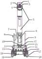
图1是本发明实施例提供的无人值守机房巡检机器人结构示意图;1 is a schematic structural diagram of an unattended machine room inspection robot provided by an embodiment of the present invention;
图2是本发明实施例提供的旋转云台结构示意图;2 is a schematic structural diagram of a rotary head provided by an embodiment of the present invention;
图中:1、网络摄像头;2、红外摄像头;3、高清相机;4、旋转云台;5、升降丝杠;6、升降电机;7、图传AP;8、手动急停;9、图传天线;10、深度摄像头;11、底盘;12、激光雷达;13、计算机;14、超声波传感器;15、碰撞传感器;16、减震机构;17、驱动轮;18、防跌落传感器;19、电池;20、从动轮;21、相机固定槽;22、第二云台电机;23、俯仰限位销;24、摄像头支架;25、第一云台电机;26、固定螺丝;27、云台托架;28、水平限位销。In the picture: 1. Network camera; 2. Infrared camera; 3. HD camera; 4. Rotating head; 5. Lifting screw; 6. Lifting motor; 7. Image transmission AP; 8. Manual emergency stop; 9. Figure Transmission antenna; 10. Depth camera; 11. Chassis; 12. Lidar; 13. Computer; 14. Ultrasonic sensor; 15. Collision sensor; 16. Damping mechanism; 17. Drive wheel; 18. Anti-drop sensor; 19. battery; 20, driven wheel; 21, camera fixing slot; 22, second gimbal motor; 23, pitch limit pin; 24, camera bracket; 25, first gimbal motor; 26, fixing screw; 27, gimbal Bracket; 28. Horizontal limit pin.
具体实施方式Detailed ways
为了使本发明的目的、技术方案及优点更加清楚明白,以下结合实施例,对本发明进行进一步详细说明。应当理解,此处所描述的具体实施例仅仅用以解释本发明,并不用于限定本发明。In order to make the objectives, technical solutions and advantages of the present invention clearer, the present invention will be further described in detail below with reference to the embodiments. It should be understood that the specific embodiments described herein are only used to explain the present invention, but not to limit the present invention.
根据对中继站现场勘查的情况分析,得出以下几点:According to the analysis of the site survey of the relay station, the following points are drawn:
机房地板平坦,没有高低起伏,无需爬坡,则机器人可选择两轮差速的驱动结构,附带两个万向支撑轮。根据现有驱动轮和万向轮设计,机身最大承重不能超过80Kg。中继站内机柜数量多,监测点位多,而且高度有些差异,最高可达2.2m,因此机器人搭载的云台应可升降,同时云台要有俯仰和左右方向的转动角度范围。中继站内设备众多,存在各种电磁干扰,机器人应能在这种环境下长期安全可靠的运行。中继站内机柜之间通道有些比较狭窄,在设计机器人时要考虑最小通道宽度,既能自由安全的运行,又不能碰触机架上的任何器材。中继站内监控点位多,和服务器交换的数据就较大,为了避免对通讯线路的带宽占用,机器人需要具备对信息前端处理的能力,将大量数据在机器人本体进行处理,只将处理结果和远端服务器进行交互。If the floor of the machine room is flat, there is no ups and downs, and there is no need to climb slopes, the robot can choose a two-wheel differential drive structure with two universal support wheels. According to the existing drive wheel and universal wheel design, the maximum load-bearing capacity of the fuselage cannot exceed 80Kg. There are many cabinets in the relay station, many monitoring points, and the height is somewhat different, up to 2.2m. Therefore, the gimbal carried by the robot should be able to lift and lower, and the gimbal must have a range of pitch and rotation angles in the left and right directions. There are many devices in the relay station, and there are various electromagnetic interferences. The robot should be able to operate safely and reliably for a long time in this environment. The passages between the cabinets in the relay station are somewhat narrow. The minimum passage width should be considered when designing the robot, which can run freely and safely without touching any equipment on the rack. There are many monitoring points in the relay station, and the data exchanged with the server is large. In order to avoid the bandwidth occupation of the communication line, the robot needs to have the ability to process the information front-end, process a large amount of data in the robot body, and only process the results and the remote. interact with the end server.
本发明提供了一种无人值守机房巡检机器人能够实现以下功能:自主导航定位、设备图像智能识别、自主避障安全防护、电池管理、简单的用户操作页面、云台的俯仰、左右转动控制,下面结合附图对本发明作详细的描述。The invention provides an unattended machine room inspection robot capable of realizing the following functions: autonomous navigation and positioning, intelligent recognition of equipment images, autonomous obstacle avoidance safety protection, battery management, simple user operation pages, pan-tilt pitch, left-right rotation control , the present invention will be described in detail below in conjunction with the accompanying drawings.
如图1所示,底盘11的平面中心固定连接有激光雷达12,平面中心上方连接有深度摄像头10,平面边缘位置上方连接有图传天线9,平面上方一侧连接有图传AP7,平面上方内部连接有升降电机6,升降电机6上方连接有升降丝杠5,升降丝杠5上端连接旋转云台4;底盘11的下端连接有驱动轮17和从动轮20,驱动轮17和从动轮20上方连接有碰撞传感器15和减震机构16;底盘11之间通过横板连接,横板上方依次固定有超声波传感器14,超声波传感器14的后方设置有计算机13,横板的下方设置有电池19。As shown in FIG. 1 , a
其中,底盘11的数量为1个。Among them, the number of the
其中,激光雷达12的扫面范围可达360°。Among them, the scanning range of the
本发明设置的激光雷达12扫描速度快,建立地图快,检测障碍物更加全面;设置的激光雷达12、深度摄像头10、超声波传感器14可以采集环境信息、绘制2D地图,并更具生成的地图设定巡检任务以及生成移动路线;设置的驱动轮17和从动轮20可使装置按照规划好的路线进行移动,设置的图传AP可以使工作人员与计算机13进行信息交互。本发明首先预先设定的巡检时间和顺序,对机房内设备进行自动巡检监测,并实现远程调度联动,可以信号集中监测系统进行联动,实现对故障设备的及时、准确定位,有助于快速指导铁路现场的设备故障处理,减少延时时间。The
如图1所示,旋转云台4上方固定有高清相机3、红外摄像头2和网络摄像头1。As shown in FIG. 1 , a high-
其中,旋转云台4上下转动范围为-45°至45°,左右转动范围为-90°至90°。Wherein, the rotation range of the
本发明设置的旋转云台4可以根据待巡检设备的角度进行调整。The
如图2所示,旋转云台4通过云台托架27的竖直板固定在升降丝杠5上,云台托架27上方水平板通过固定螺丝28固定第一云台电机25。As shown in FIG. 2 , the rotating pan/
本发明设置的云台托架27可使升降丝杠5带动旋转云台4进行高度的调节,以实现与待巡检设备的高度匹配。The
如图2所示,第一云台电机25的左侧设置有水平限位销28,第一云台电机25的上方通过螺栓连接有摄像头支架24。As shown in FIG. 2 , a
本发明设置的水平限位销28可以控制摄像头支架24的水平转动范围,防止旋转过大,对数据传输线造成损害。The
如图2所示,摄像头支架24上方左侧连接有俯仰限位销23,右侧连接有第二云台电机22,第二云台电机22连接有相机固定槽21。As shown in FIG. 2 , the upper left side of the
其中,相机固定槽21可装载三个摄像头。Among them, the
本发明设置的第二云台电机22可以带动相机固定槽21进行旋转,同时俯仰限位销23控制上下转动的范围,防止旋转过大,对数据传输线造成损害。The
本发明在使用时,首先工作人员通过图传天线9对图传AP7进行下发巡检指令,激光雷达12、深度摄像头10、超声波传感器14可以采集环境信息、绘制2D地图,并更具生成的地图设定巡检任务以及生成移动路线;激光雷达12、深度摄像头10、超声波传感器14、防跌落传感器18基于绘制的2D地图数据实现融合导航服务,可以灵活面对复杂多变的实际应用环境,驱动轮17和从动轮20可使装置按照规划好的路线进行移动;当到达指定巡检位置时,可能业务装置的高度与待巡检设备的高度不匹配,不利于进行巡检操作,因此可以通过升降电机6和升降丝杠5配合,调整所述业务装置的高度,调整至便于执行所述巡检操作的高度。When the present invention is in use, firstly, the staff issues inspection instructions to the image transmission AP7 through the
以上所述,仅为本发明的具体实施方式,但本发明的保护范围并不局限于此,任何熟悉本技术领域的技术人员在本发明揭露的技术范围内,凡在本发明的精神和原则之内所作的任何修改、等同替换和改进等,都应涵盖在本发明的保护范围之内。The above are only specific embodiments of the present invention, but the protection scope of the present invention is not limited to this. Any person skilled in the art is within the technical scope disclosed by the present invention, and all within the spirit and principle of the present invention Any modifications, equivalent replacements and improvements made within the scope of the present invention should be included within the protection scope of the present invention.
Claims (10)
Priority Applications (1)
| Application Number | Priority Date | Filing Date | Title |
|---|---|---|---|
| CN202010376409.9ACN111438677A (en) | 2020-05-07 | 2020-05-07 | Robot is patrolled and examined to unmanned on duty computer lab |
Applications Claiming Priority (1)
| Application Number | Priority Date | Filing Date | Title |
|---|---|---|---|
| CN202010376409.9ACN111438677A (en) | 2020-05-07 | 2020-05-07 | Robot is patrolled and examined to unmanned on duty computer lab |
Publications (1)
| Publication Number | Publication Date |
|---|---|
| CN111438677Atrue CN111438677A (en) | 2020-07-24 |
Family
ID=71653646
Family Applications (1)
| Application Number | Title | Priority Date | Filing Date |
|---|---|---|---|
| CN202010376409.9APendingCN111438677A (en) | 2020-05-07 | 2020-05-07 | Robot is patrolled and examined to unmanned on duty computer lab |
Country Status (1)
| Country | Link |
|---|---|
| CN (1) | CN111438677A (en) |
Cited By (12)
| Publication number | Priority date | Publication date | Assignee | Title |
|---|---|---|---|---|
| CN111897346A (en)* | 2020-08-17 | 2020-11-06 | 国网河南省电力公司新安县供电公司 | An adjustable substation power inspection device |
| CN112025727A (en)* | 2020-08-27 | 2020-12-04 | 江苏师范大学 | Novel patrol and examine track robot device |
| CN112363159A (en)* | 2020-10-09 | 2021-02-12 | 安徽博微长安电子有限公司 | Through-wall detection radar with autonomous movement energy |
| CN112405552A (en)* | 2020-11-03 | 2021-02-26 | 山东新一代信息产业技术研究院有限公司 | Intelligent inspection robot |
| CN113031615A (en)* | 2021-03-11 | 2021-06-25 | 京东数科海益信息科技有限公司 | Inspection robot |
| CN113391636A (en)* | 2021-07-02 | 2021-09-14 | 广东工贸职业技术学院 | Ultrasonic sensing obstacle avoidance's thing networking intelligence patrols and guards against robot based on 5G communication |
| CN114399851A (en)* | 2021-12-24 | 2022-04-26 | 中国农业银行股份有限公司云南省分行 | A kind of intelligent equipment and system for inspection machine room |
| CN114488165A (en)* | 2022-02-11 | 2022-05-13 | 山东省地质矿产勘查开发局第一地质大队(山东省第一地质矿产勘查院) | Survey and drawing geographic information field inspection auxiliary device based on unmanned aerial vehicle |
| CN115022533A (en)* | 2022-05-11 | 2022-09-06 | 黄河科技学院 | A computer-controlled parking lot remote monitoring device and construction method |
| CN115922737A (en)* | 2023-02-24 | 2023-04-07 | 河南安元工业互联网科技有限公司 | A multifunctional safety inspection robot |
| CN116156286A (en)* | 2022-11-29 | 2023-05-23 | 云南电网有限责任公司昆明供电局 | Remote patrol site investigation device and application method thereof |
| CN114333096B (en)* | 2021-04-09 | 2023-12-15 | 北京市燃气集团有限责任公司 | Inspection robot |
Citations (8)
| Publication number | Priority date | Publication date | Assignee | Title |
|---|---|---|---|---|
| CN201803063U (en)* | 2010-07-20 | 2011-04-20 | 周惠兴 | Two-degree-of-freedom pan/tilt/zoom mechanism |
| CN102095060A (en)* | 2009-12-09 | 2011-06-15 | 天津天地伟业数码科技有限公司 | Machine core structure of heavy load holder |
| CN202748139U (en)* | 2012-07-11 | 2013-02-20 | 北京中电金桥电网技术开发有限公司 | Automatic inspecting and temperature-measuring device for transformer substation |
| CN107959254A (en)* | 2018-01-04 | 2018-04-24 | 杭州申昊科技股份有限公司 | One kind hangs rail intelligent inspection robot |
| CN109079740A (en)* | 2018-09-04 | 2018-12-25 | 南京理工大学 | A kind of Intelligent Mobile Robot |
| CN210142861U (en)* | 2019-05-17 | 2020-03-13 | 贵州电网有限责任公司 | Miniaturized indoor inspection robot with autonomous lifting cradle head |
| CN110966496A (en)* | 2019-12-12 | 2020-04-07 | 浙江大学 | Three-degree-of-freedom precision positioning shooting cloud platform with harmonic reducer |
| CN212218460U (en)* | 2020-05-07 | 2020-12-25 | 西安瑞信铁路设备有限公司 | Robot is patrolled and examined to unmanned on duty computer lab |
- 2020
- 2020-05-07CNCN202010376409.9Apatent/CN111438677A/enactivePending
Patent Citations (8)
| Publication number | Priority date | Publication date | Assignee | Title |
|---|---|---|---|---|
| CN102095060A (en)* | 2009-12-09 | 2011-06-15 | 天津天地伟业数码科技有限公司 | Machine core structure of heavy load holder |
| CN201803063U (en)* | 2010-07-20 | 2011-04-20 | 周惠兴 | Two-degree-of-freedom pan/tilt/zoom mechanism |
| CN202748139U (en)* | 2012-07-11 | 2013-02-20 | 北京中电金桥电网技术开发有限公司 | Automatic inspecting and temperature-measuring device for transformer substation |
| CN107959254A (en)* | 2018-01-04 | 2018-04-24 | 杭州申昊科技股份有限公司 | One kind hangs rail intelligent inspection robot |
| CN109079740A (en)* | 2018-09-04 | 2018-12-25 | 南京理工大学 | A kind of Intelligent Mobile Robot |
| CN210142861U (en)* | 2019-05-17 | 2020-03-13 | 贵州电网有限责任公司 | Miniaturized indoor inspection robot with autonomous lifting cradle head |
| CN110966496A (en)* | 2019-12-12 | 2020-04-07 | 浙江大学 | Three-degree-of-freedom precision positioning shooting cloud platform with harmonic reducer |
| CN212218460U (en)* | 2020-05-07 | 2020-12-25 | 西安瑞信铁路设备有限公司 | Robot is patrolled and examined to unmanned on duty computer lab |
Non-Patent Citations (4)
| Title |
|---|
| R.帕特里克·戈贝尔: "《ROS入门实例》", 31 January 2016, 中山大学出版社, pages: 7 - 8* |
| 曹其新、张蕾: "《轮式自主移动机器人》", 31 January 2012, 上海交通大学出版社, pages: 14 - 16* |
| 谭建豪: "《数字图像处理与移动机器人路径规划》", 30 April 2013, 华中科技大学出版社, pages: 337* |
| 陈传志,陈金宝,聂宏: "《航天器冗余机械臂避障路径规划与环境感知》", 31 October 2019, 哈尔滨工程大学出版社, pages: 14* |
Cited By (16)
| Publication number | Priority date | Publication date | Assignee | Title |
|---|---|---|---|---|
| CN111897346A (en)* | 2020-08-17 | 2020-11-06 | 国网河南省电力公司新安县供电公司 | An adjustable substation power inspection device |
| CN111897346B (en)* | 2020-08-17 | 2024-06-21 | 国网河南省电力公司新安县供电公司 | Adjustable substation power inspection device |
| CN112025727A (en)* | 2020-08-27 | 2020-12-04 | 江苏师范大学 | Novel patrol and examine track robot device |
| CN112363159B (en)* | 2020-10-09 | 2023-12-08 | 安徽博微长安电子有限公司 | Through-wall detection radar with autonomous movement capability |
| CN112363159A (en)* | 2020-10-09 | 2021-02-12 | 安徽博微长安电子有限公司 | Through-wall detection radar with autonomous movement energy |
| CN112405552A (en)* | 2020-11-03 | 2021-02-26 | 山东新一代信息产业技术研究院有限公司 | Intelligent inspection robot |
| CN113031615A (en)* | 2021-03-11 | 2021-06-25 | 京东数科海益信息科技有限公司 | Inspection robot |
| CN114333096B (en)* | 2021-04-09 | 2023-12-15 | 北京市燃气集团有限责任公司 | Inspection robot |
| CN113391636A (en)* | 2021-07-02 | 2021-09-14 | 广东工贸职业技术学院 | Ultrasonic sensing obstacle avoidance's thing networking intelligence patrols and guards against robot based on 5G communication |
| CN114399851A (en)* | 2021-12-24 | 2022-04-26 | 中国农业银行股份有限公司云南省分行 | A kind of intelligent equipment and system for inspection machine room |
| CN114488165A (en)* | 2022-02-11 | 2022-05-13 | 山东省地质矿产勘查开发局第一地质大队(山东省第一地质矿产勘查院) | Survey and drawing geographic information field inspection auxiliary device based on unmanned aerial vehicle |
| CN114488165B (en)* | 2022-02-11 | 2022-10-25 | 山东省地质矿产勘查开发局第一地质大队(山东省第一地质矿产勘查院) | Survey and drawing geographic information field inspection auxiliary device based on unmanned aerial vehicle |
| CN115022533A (en)* | 2022-05-11 | 2022-09-06 | 黄河科技学院 | A computer-controlled parking lot remote monitoring device and construction method |
| CN116156286A (en)* | 2022-11-29 | 2023-05-23 | 云南电网有限责任公司昆明供电局 | Remote patrol site investigation device and application method thereof |
| CN116156286B (en)* | 2022-11-29 | 2024-09-27 | 云南电网有限责任公司昆明供电局 | Remote patrol site investigation device and application method thereof |
| CN115922737A (en)* | 2023-02-24 | 2023-04-07 | 河南安元工业互联网科技有限公司 | A multifunctional safety inspection robot |
Similar Documents
| Publication | Publication Date | Title |
|---|---|---|
| CN111438677A (en) | Robot is patrolled and examined to unmanned on duty computer lab | |
| CN110647145B (en) | Security-based ground mobile robot and unmanned aerial vehicle collaborative operation system and method | |
| CN114253300B (en) | Unmanned aerial vehicle inspection system and method for gridding machine nest | |
| CN105835063B (en) | Crusing robot system and its method for inspecting in a kind of substation room | |
| CN204913887U (en) | Unattended substation indoor tour of protection and reconnaissance robot | |
| CN105807776A (en) | Machine room unmanned inspection robot | |
| CN109412079B (en) | A transmission line UAV inspection system | |
| CN107368083A (en) | A kind of crusing robot and crusing robot system | |
| CN109066422A (en) | A kind of substation inspection system | |
| CN109324649A (en) | A kind of substation compound inspection system and method | |
| WO2018040581A1 (en) | Auxiliary operation robot for medium and low speed maglev | |
| CN207281591U (en) | A kind of crusing robot and crusing robot system | |
| CN206131993U (en) | A medium-low speed magnetic levitation F-track inspection robot | |
| CN206287133U (en) | It is a kind of can autonomous upper and lower elevator building inspecting robot | |
| CN212218460U (en) | Robot is patrolled and examined to unmanned on duty computer lab | |
| WO2023184975A1 (en) | Automatic charging hangar and system for unmanned aerial vehicle, and inspection method | |
| CN116638529A (en) | Coal chemical air-ground integrated joint inspection and search robot and working method thereof | |
| CN209795830U (en) | Pipe gallery inspection device | |
| CN115309185A (en) | Unmanned aerial vehicle positioning and tracking system for inspection | |
| CN114977006A (en) | Unmanned aerial line inspection device and method | |
| CN118560726A (en) | Rail surface damage detecting system | |
| CN219325239U (en) | Warehouse fire safety inspection robot | |
| CN117104565A (en) | Drone smart mobile nest | |
| CN116404746A (en) | An intelligent inspection and early warning system for substation equipment | |
| CN209640707U (en) | A kind of vehicle-mounted unmanned aerial vehicle ground control system |
Legal Events
| Date | Code | Title | Description |
|---|---|---|---|
| PB01 | Publication | ||
| PB01 | Publication | ||
| SE01 | Entry into force of request for substantive examination | ||
| SE01 | Entry into force of request for substantive examination | ||
| RJ01 | Rejection of invention patent application after publication | ||
| RJ01 | Rejection of invention patent application after publication | Application publication date:20200724 |