CN111436983A - Microsurgery operation tractive ware - Google Patents
Microsurgery operation tractive wareDownload PDFInfo
- Publication number
- CN111436983A CN111436983ACN202010271170.9ACN202010271170ACN111436983ACN 111436983 ACN111436983 ACN 111436983ACN 202010271170 ACN202010271170 ACN 202010271170ACN 111436983 ACN111436983 ACN 111436983A
- Authority
- CN
- China
- Prior art keywords
- base plate
- microsurgical
- pulling
- stretcher
- edge
- Prior art date
- Legal status (The legal status is an assumption and is not a legal conclusion. Google has not performed a legal analysis and makes no representation as to the accuracy of the status listed.)
- Pending
Links
Images


Classifications
- A—HUMAN NECESSITIES
- A61—MEDICAL OR VETERINARY SCIENCE; HYGIENE
- A61B—DIAGNOSIS; SURGERY; IDENTIFICATION
- A61B17/00—Surgical instruments, devices or methods
- A61B17/02—Surgical instruments, devices or methods for holding wounds open, e.g. retractors; Tractors
- A—HUMAN NECESSITIES
- A61—MEDICAL OR VETERINARY SCIENCE; HYGIENE
- A61B—DIAGNOSIS; SURGERY; IDENTIFICATION
- A61B90/00—Instruments, implements or accessories specially adapted for surgery or diagnosis and not covered by any of the groups A61B1/00 - A61B50/00, e.g. for luxation treatment or for protecting wound edges
- A61B90/30—Devices for illuminating a surgical field, the devices having an interrelation with other surgical devices or with a surgical procedure
- A—HUMAN NECESSITIES
- A61—MEDICAL OR VETERINARY SCIENCE; HYGIENE
- A61B—DIAGNOSIS; SURGERY; IDENTIFICATION
- A61B17/00—Surgical instruments, devices or methods
- A61B17/02—Surgical instruments, devices or methods for holding wounds open, e.g. retractors; Tractors
- A61B2017/0287—Surgical instruments, devices or methods for holding wounds open, e.g. retractors; Tractors with elastic retracting members connectable to a frame, e.g. hooked elastic wires
- A—HUMAN NECESSITIES
- A61—MEDICAL OR VETERINARY SCIENCE; HYGIENE
- A61B—DIAGNOSIS; SURGERY; IDENTIFICATION
- A61B90/00—Instruments, implements or accessories specially adapted for surgery or diagnosis and not covered by any of the groups A61B1/00 - A61B50/00, e.g. for luxation treatment or for protecting wound edges
- A61B90/30—Devices for illuminating a surgical field, the devices having an interrelation with other surgical devices or with a surgical procedure
- A61B2090/309—Devices for illuminating a surgical field, the devices having an interrelation with other surgical devices or with a surgical procedure using white LEDs
Landscapes
- Health & Medical Sciences (AREA)
- Surgery (AREA)
- Life Sciences & Earth Sciences (AREA)
- Heart & Thoracic Surgery (AREA)
- Engineering & Computer Science (AREA)
- Biomedical Technology (AREA)
- Nuclear Medicine, Radiotherapy & Molecular Imaging (AREA)
- Medical Informatics (AREA)
- Molecular Biology (AREA)
- Animal Behavior & Ethology (AREA)
- General Health & Medical Sciences (AREA)
- Public Health (AREA)
- Veterinary Medicine (AREA)
- Pathology (AREA)
- Oral & Maxillofacial Surgery (AREA)
- Surgical Instruments (AREA)
Abstract
Translated fromChinese
Description
Translated fromChinese技术领域technical field
本发明属于外科器械及装置领域,具体涉及一种用于显微外科手术的支架。The invention belongs to the field of surgical instruments and devices, in particular to a support for microsurgery.
背景技术Background technique
显微外科是研究利用光学放大设备和显微外科器材,进行精细手术的学科,是手术学科各个专业都可采用的一门外科技术,如妇科显微镜外科、泌尿显微镜外科、神经显微镜外科等。手术做得更快更好是显微外科发展的一个重要需求。Microsurgery is a discipline that studies the use of optical magnification equipment and microsurgical equipment to perform fine surgery. Doing faster and better surgery is an important requirement for the development of microsurgery.
以当前泌尿显微镜外科的情况为例来说,精索静脉曲张(varicocele,VC)是泌尿外科常见病,发病率较高,多见于青壮年男性,成年男性人群发病率约15%,男性不育症患者发病率约40%,合并疼痛不适发病率约20%。精索静脉曲张是由于精索内蔓状静脉丛回流不畅而形成局部静脉扩张、迂曲、延长的病理现象,可导致患者睾丸发育滞缓和体积减少、阴囊坠胀不适,是目前已知的导致男性不育的一个重要原因,外科手术是其主要的治疗方式。精索组织较小,内部结构复杂。传统的开放手术复发率高,且具有阴囊水肿、睾丸动脉损伤、睾丸萎缩、鞘膜积液等多种并发症发生的可能,因手术效果不够理想而正逐渐被淘汰。如今普遍采用的是显微精索静脉结扎术(microsurgical varicocelectomy, MV),这种手术在放大5-10倍的显微镜下进行,在显微镜视野中仔细辨认出输精管、精索动脉、静脉和淋巴管的基础上,结扎除输精管静脉以外的所有静脉,具有损伤小、复发率低、术后并发症少,而且症状缓解及精子改善等优点。MV已成为手术治疗VC的“金标准”,目前在各类专科或综合医院全面展开,且显微精索静脉结扎手术量都越来越大。Taking the current situation of urological microscopy as an example, varicocele (VC) is a common disease in urology, with a high incidence rate, which is more common in young and middle-aged men. The incidence of adult male population is about 15%, and male infertility. About 40% of patients with the disease, and about 20% of patients with combined pain and discomfort. Varicocele is a pathological phenomenon of local venous dilatation, tortuosity, and prolongation due to the poor return of the venous plexus in the spermatic cord, which can lead to testicular growth retardation, volume reduction, and discomfort in the scrotum. It is currently known to cause An important cause of male infertility, surgery is the main treatment. The spermatic cord is small and has a complex internal structure. Traditional open surgery has a high recurrence rate, and has the possibility of various complications such as scrotal edema, testicular artery injury, testicular atrophy, and hydrocele. Microsurgical varicocelectomy (MV) is commonly used today, which is performed under a microscope with a magnification of 5-10 times, and the vas deferens, spermatic arteries, veins and lymphatic vessels are carefully identified in the microscope field of view On the basis of the ligation of all veins except the vas deferens, it has the advantages of less damage, low recurrence rate, less postoperative complications, symptom relief and sperm improvement. MV has become the "gold standard" for surgical treatment of VC, and is currently being carried out in various specialized or general hospitals, and the volume of microscopic spermatic vein ligation is increasing.
如前所述进行显微精索静脉结扎手术要取得理想效果的前提是将输精管、精索动脉、精索静脉及淋巴管等逐一鉴别、游离,在重点保护好输精管、精索动脉的基础上,结扎除输精管静脉以外所有静脉;保护好睾丸动脉是手术成功关键。手术在一个固定的平面进行,不能漏扎或误扎是对医生的基本要求。实际情况是精索内静脉在阴囊内是静脉丛,在腹股沟管内汇集成多支,存在漏扎静脉的可能性,如果有漏扎的静脉,就有疾病复发的可能;如此多的脉管组织,确实难以完全暴露;且有时不易鉴别精索动脉与静脉,因此带来较大的手术难度。As mentioned above, the premise of microscopic spermatic vein ligation to achieve ideal results is to identify and dissociate the vas deferens, spermatic artery, spermatic vein and lymphatic vessels one by one, on the basis of focusing on protecting the vas deferens and spermatic artery. , ligation of all veins except the vas deferens; protection of the testicular artery is the key to the success of the operation. The operation is performed on a fixed plane, and it is a basic requirement for doctors that the ligation cannot be missed or mistakenly ligated. The actual situation is that the internal spermatic vein is a venous plexus in the scrotum, and it converges into multiple branches in the inguinal canal. There is a possibility of missing veins. If there are missed veins, there is a possibility of disease recurrence; so many vascular tissues , it is indeed difficult to fully expose; and sometimes it is difficult to identify the spermatic artery and vein, so it brings greater surgical difficulty.
由此可以了解,在显微外科手术中,明确辨别各种组织,精准处理需要治疗的部位并且不影响其周围组织,是手术效果的关键因素,也是医生进行外科手术过程中的重点工作。It can be understood from this that in microsurgery, clearly identifying various tissues, accurately treating the parts that need to be treated without affecting the surrounding tissues, is the key factor for the surgical effect, and it is also the key work of the doctor during the surgical operation.
现有技术中实现显微外科手术的这项要求很大程度上还是依靠手术显微镜和医生的技巧与经验。手术显微镜使得辨别微小结构成为可能,但实践中可以知道,手术显微镜是一个光学调节系统,且镜头大小限制了操作视野;医生的眼睛本身也是一个光学调节系统,必须与手术显微镜的光学成像系统配合好之后,才能在其视网膜上接收到清晰的手术区域成像。实践操作医生也不可能一直盯着手术显微镜头,难免有移开的时候,再回来操作时,还要重新再找一次操作部位。就算整个手术过程不移开镜头,每一步操作也要在镜头视野中确定一次操作部位,避开相邻组织。所以单靠手术显微镜找准部位避开相邻组织,手术工作效率受到限制,手术效果受医生本身的技巧和经验的影响很大,不利于显微外科手术的推广应用,同时医生的疲劳程度较高。This requirement in the prior art to achieve microsurgery is still largely dependent on the skill and experience of the operating microscope and the physician. The surgical microscope makes it possible to identify tiny structures, but in practice, it can be known that the surgical microscope is an optical adjustment system, and the size of the lens limits the operating field of view; the doctor's eye itself is also an optical adjustment system, which must be matched with the optical imaging system of the surgical microscope Only then can clear images of the surgical area be received on their retinas. It is also impossible for the practice doctor to keep staring at the operating microscope head. It is inevitable that when it is removed, when it comes back to operate, it is necessary to find the operation site again. Even if the lens is not removed during the entire surgical procedure, the operation site must be determined once in the field of view of the lens for each operation, avoiding adjacent tissues. Therefore, relying solely on the operating microscope to locate the site and avoid adjacent tissues will limit the efficiency of the operation. The effect of the operation is greatly affected by the doctor's own skills and experience, which is not conducive to the popularization and application of microsurgery. high.
为了改善这一个情况,现在发展了一些显微组织的牵拉显露技术,辅助手术野的显露和相关组织的分别。常规的如采用手外科小拉钩;血管、神经的牵开,常采用薄的橡皮片牵拉或者小型自动撑开器显露手术野。在实践中逐渐发现采用外科小拉钩或者橡皮片牵拉虽然简易但效果不够好,有时还影响手术平面的稳定。自动撑开器则结构复杂,还配有驱动电机,布置到手术区域及操作过程中不够简便,且器械配备价格高。In order to improve this situation, some techniques for pulling and revealing microscopic tissues have been developed, which assist the exposure of the surgical field and the distinction of related tissues. For routine use, small retractors for hand surgery are used; for retraction of blood vessels and nerves, a thin rubber sheet is often used for retraction or a small automatic spreader is used to expose the surgical field. In practice, it is gradually found that the use of small surgical retractors or rubber sheets is simple but the effect is not good enough, and sometimes affects the stability of the surgical plane. The automatic spreader has a complex structure and is also equipped with a drive motor, which is not easy to arrange in the surgical area and during the operation, and the equipment is expensive.
因此,提供一种能够有效辅助分离微小组织、辨明施术位置且结构简洁,配备方便、容易操作兼顾成本的显微外科手术牵张器对医生的实际工作和提高手术效率有积极的意义和必要性。Therefore, to provide a microsurgical stretcher that can effectively assist in the separation of tiny tissues, identify the surgical site, has a simple structure, is convenient to equip, is easy to operate, and takes into account the cost has positive significance and necessity for the actual work of doctors and the improvement of surgical efficiency. sex.
发明内容SUMMARY OF THE INVENTION
本发明目的在于提供一种显微外科手术牵张器,能够有效牵拉分开微小组织,仅将需要手术的位置露出,结构简单,易用易配备。The purpose of the present invention is to provide a microsurgical stretcher, which can effectively stretch and separate tiny tissues, and only expose the position that needs to be operated. The structure is simple, easy to use and easy to equip.
本发明提供的一种显微外科手术牵张器,包括基板和牵拉机构;所述基板的边缘之内是手术视野区,所述基板包括固定部,所述固定部将所述基板固定在所需位置,例如手术巾上。所述牵拉机构固定连接在所述基板靠近边缘的部位。在手术实践中医生用所述牵拉机构将手术区中需要保留的邻近组织牵拉到所述基板边缘附近,将需要实施手术组织始终暴露在手术视野区内,一目了然,以便医生能很快在手术显微镜的视野中部准确找到应当操作部位,有效避免误伤,提高了手术效率。A microsurgical stretcher provided by the present invention includes a base plate and a pulling mechanism; the edge of the base plate is a surgical field of view, and the base plate includes a fixing part, and the fixing part fixes the base plate on the desired location, e.g. on a surgical drape. The pulling mechanism is fixedly connected to the position of the base plate close to the edge. In the surgical practice, the doctor uses the pulling mechanism to pull the adjacent tissue that needs to be preserved in the operation area to the vicinity of the edge of the base plate, so that the tissue that needs to be operated is always exposed in the operation field of view, which is clear at a glance, so that the doctor can quickly The middle of the field of view of the operating microscope can accurately find the part that should be operated, which can effectively avoid accidental injury and improve the efficiency of the operation.
具体的,在本发明提供的显微外科手术牵张器中,所述固定部是一种无需额外工具就能快速拆开和安装的快拆装结构。优选的,所述固定部包括背胶,魔术贴或夹子的一种或者几种的组合。Specifically, in the microsurgical stretcher provided by the present invention, the fixing portion is a quick-release structure that can be quickly disassembled and installed without additional tools. Preferably, the fixing portion includes one or a combination of adhesives, Velcro or clips.
在一个可行的实施方案中,所述基板是一块矩形平板,所述牵拉机构固定连接在所述基板的两侧边缘。手术实践中需要一个固定的手术平面将整个手术部位从切口中游离出来放置于这个平面上进行操作,所述基板位于手术视野区并提供了这样一个稳定的手术操作平面,同时所述牵拉机构设置在所述基板的两条矩形边上,另外两条侧边则是敞开的;将需要保留的组织牵拉向矩形两侧,利于组织间充足的间距,便于医生将游离出的手术部分从侧面放置到所述基板上,也方便医生从所述的显微外科手术牵张器两侧进行手术操作。In a feasible embodiment, the base plate is a rectangular flat plate, and the pulling mechanism is fixedly connected to the two edges of the base plate. In surgical practice, a fixed surgical plane is required to free the entire surgical site from the incision and place it on this plane for operation. The base plate is located in the surgical field of view and provides such a stable surgical operating plane. At the same time, the pulling mechanism It is arranged on two rectangular sides of the base plate, and the other two sides are open; the tissue that needs to be retained is pulled to both sides of the rectangle, which is conducive to sufficient spacing between the tissues, and it is convenient for the doctor to remove the freed surgical part from the The side is placed on the base plate, which is also convenient for doctors to perform surgical operations from both sides of the microsurgical stretcher.
在一个效果很好的实施方案里,所述基板是用半透光材质制作的。在显微外科手术中视野区照明光线强弱和分布对于观察清晰度,操作效果有直接的影响。部位区域光太强,容易产生强反光影响医生观察,同时也加大医生眼睛的疲劳度。用半透光材质制作的所述基板能够有效的减少强反光,优化手术操作区域的整体光分布。In a very effective embodiment, the substrate is made of a translucent material. In microsurgery, the intensity and distribution of illumination light in the visual field have a direct impact on the clarity of observation and the effect of operation. If the light in the area is too strong, it is easy to produce strong reflections, which will affect the doctor's observation and increase the fatigue of the doctor's eyes. The substrate made of translucent material can effectively reduce strong reflection and optimize the overall light distribution in the surgical operation area.
进一步的,所述基板表面设置有匀光膜;在所述基板底部背离所述牵拉机构,及朝向所需使用位置,例如手术巾的一面设置有光源。打开光源时,手术视野区的光线分布均匀,照明更充分且柔和,更有利于各细微组织的识别和手术操作,一定程度上减轻了医生的眼疲劳。Further, the surface of the substrate is provided with a light homogenizing film; a light source is provided on the bottom of the substrate facing away from the pulling mechanism and facing the desired use position, such as a surgical towel. When the light source is turned on, the light distribution in the surgical field of view is uniform, and the illumination is more sufficient and soft, which is more conducive to the identification of various fine tissues and surgical operations, and reduces the eye fatigue of doctors to a certain extent.
在另一个有效的实施例中,在本发明提供的显微外科手术牵张器中,还可以具有这样的特征:其中,所述牵拉机构包括标识支柱和牵拉组件;所述标识支柱底端固定连接在所述基板靠近边缘的部位;所述牵拉组件的一端与所述标识支柱固定连接,所述牵拉组件的另一端绕经需要保留的组织并将其牵拉向所述标识支柱。所述标识支柱上可以标注记号或贴标签,在不影响手术操作的情况下,帮助区分各个组织。In another effective embodiment, the microsurgical retractor provided by the present invention may also have the following features: wherein the retracting mechanism includes a marking post and a retracting assembly; the bottom of the marking post The end is fixedly connected to the position of the base plate close to the edge; one end of the pulling component is fixedly connected to the marking support, and the other end of the pulling component goes around the tissue to be retained and pulls it towards the marking pillar. Marks or labels can be marked on the identification pillar to help distinguish each tissue without affecting the surgical operation.
具体的,所述标识支柱至少有两个,固定在所述基板上相对的边缘附近;每个所述标识支柱与一个牵拉组件相配套。如此可以将不需要手术操作的组织分离到手术视野区两侧,更容易识别组织,更有效的避免误触碰。Specifically, there are at least two identification pillars, which are fixed near opposite edges of the base plate; each of the identification pillars is matched with a pulling component. In this way, tissues that do not require surgical operations can be separated to both sides of the surgical field of view, making it easier to identify the tissues and more effectively avoiding accidental touch.
在一个特别好的实施方案中所述标识支柱底部设置有与所述基板边缘相配合的底部快拆装结构,所述底部快拆装结构将所述标识支柱与所述基板固定连接,并能够根据手术实际需要,将标识支柱设置固定在所述基板边缘附近的任何预设位置,同时所述底部快拆装结构便于快速的改变固定位置并连接到新的位置,利于手术的灵活操作。所述底部快拆装结构可以是夹子、与所述基板配合设置的卡扣结构等等。In a particularly preferred embodiment, the bottom of the identification pillar is provided with a bottom quick-release structure matched with the edge of the substrate, and the bottom quick-release structure fixedly connects the identification pillar and the substrate, and can According to the actual needs of the operation, the identification pillar is arranged and fixed at any preset position near the edge of the base plate, and the bottom quick-release structure is convenient to quickly change the fixed position and connect to a new position, which is conducive to the flexible operation of the operation. The bottom quick-release structure may be a clip, a snap-fit structure matched with the base plate, and the like.
此外,还有一个具体的实施方案中,所述牵拉组件包括限位部和牵拉部;所述限位部的下端通过设置的第一快拆装结构固定连接到所述标识支柱上预设高度位置,其上端设置有第二快拆装结构;所述牵拉部的一端被限制在所述限位部上,另一端绕经需要保留的组织后通过所述第二快拆装结构实现与所述限位部的固定连接。所述第一快拆装结构与所述第二快拆装结构起到的作用相同,都是实现不需借助其他工具就能快速的松开或锁定连接,具体实施中可以采用夹子,限位凹槽等。这个方案中一方面被牵拉的组织不容易脱离,在整个手术的过程中始终与需要操作的部位分离,不影响手术视野,在手术完成后,不需要额外工具就能打开所述限位部的第二快拆装结构,使得所述牵拉部的一端脱离所述限位部,则被牵拉组织就恢复原样。另一方面,所述限位部下端通过第一快拆装结构固定连接到所述标识支柱上任意预设高度位置,还能够快速的根据实际需要改变连接的位置,调整牵拉高度。这样就可以从手术视野区边缘的任何位置,高度,牵拉需要的组织,而且不同的所述牵拉组件可以将不同的需要保留的组织牵拉到不同的高度上,利于不组织的区分,也避免了操作时不同组织之间出现干涉或缠绕的情况。增加了所述的显微外科手术牵张器实际应用中的灵活性,满足了手术中各种不同需求。In addition, in another specific embodiment, the pulling assembly includes a limit portion and a pulling portion; the lower end of the limit portion is fixedly connected to the identification pillar through the provided first quick-release structure. A height position is set, and the upper end is provided with a second quick disassembly and assembly structure; one end of the pulling part is restricted on the limiting part, and the other end passes through the second quick disassembly and assembly structure after passing through the tissue to be retained. A fixed connection with the limiting portion is achieved. The first quick disassembly structure has the same function as the second quick disassembly structure, both of which can be quickly released or locked without using other tools. In the specific implementation, a clip can be used to limit the position. grooves etc. In this solution, on the one hand, the pulled tissue is not easy to detach, and it is always separated from the part that needs to be operated during the whole operation, which does not affect the operation field. After the operation is completed, the limit part can be opened without additional tools. The second quick disassembly and assembly structure is provided, so that one end of the pulling part is separated from the limiting part, and the pulled tissue is restored to its original state. On the other hand, the lower end of the limiting portion is fixedly connected to any preset height position on the identification pillar through the first quick-release assembly structure, and the connection position can also be quickly changed according to actual needs, and the pulling height can be adjusted. In this way, the desired tissue can be pulled from any position and height of the edge of the surgical field of view, and different pulling components can pull different tissues that need to be retained to different heights, which is conducive to the differentiation of non-tissues. Interference or entanglement between different tissues during operation is also avoided. The flexibility in practical application of the microsurgical stretcher is increased, and various different demands in surgery are met.
优选的,所述牵拉部用具有一定弹性和张力的材料制作而成。更有利于保护被牵拉的微小组织,根据实际通过调节所述牵拉部的弹性或张力,达到合适的牵拉固定状态同时有效避免拉伤组织。Preferably, the pulling part is made of a material with certain elasticity and tension. It is more beneficial to protect the tiny tissue being pulled, and by adjusting the elasticity or tension of the pulling portion according to the actual situation, a proper pulling and fixing state can be achieved and the tissue can be effectively prevented from being pulled.
另一个优选的,与不同所述标识支柱配套的所述牵拉组件的所述牵拉部具有不同的颜色。能够更加明显的区分各个组织,利于医生实际操作。In another preferred embodiment, the pulling parts of the pulling assemblies matched with the different identification pillars have different colors. It can more clearly distinguish each tissue, which is beneficial to the doctor's actual operation.
综上所述本发明具有如下有益效果:In summary, the present invention has the following beneficial effects:
根据本发明所涉及的显微外科手术牵张器,通过所述基板与所述牵拉机构的配合,可使显微手术中不需要触及的相邻组织分离固定在特定位置,有效避免误伤,便于医生在显微镜视野中快速的找到需要操作的部位,提高了手术效率和精准性,同时结构简单,取材方便,成本低,制备容易且效果好。According to the microsurgery stretcher of the present invention, through the cooperation of the base plate and the stretching mechanism, the adjacent tissues that do not need to be touched in the microsurgery can be separated and fixed in a specific position, thereby effectively avoiding accidental injury. It is convenient for doctors to quickly find the part that needs to be operated in the field of view of the microscope, which improves the efficiency and accuracy of the operation, and at the same time, the structure is simple, the material is convenient, the cost is low, the preparation is easy and the effect is good.
通过快拆装结构实现各部分的连接,能够将不需要操作的组织牵拉在不同的位置或高度,很好的提高了实际应用中的灵活性,便于手术操作,应对手术中变化。The connection of each part is realized by the quick disassembly and assembly structure, which can pull the tissue that does not require operation at different positions or heights, which greatly improves the flexibility in practical application, facilitates surgical operation, and responds to changes during surgery.
采用所述基板提供了稳定的手术平面;增加光源和半透光材质的使用有效改善了手术视野区内的光分布,减少强反光,增加照明亮度,减轻医生长时间手术的眼疲劳程度。The use of the base plate provides a stable surgical plane; increasing the use of light sources and semi-transparent materials effectively improves the light distribution in the surgical field of view, reduces strong reflections, increases illumination brightness, and reduces eye fatigue for doctors during long-term operations.
根据实际需要可以安装不同数目的所述标识支柱,配合不同颜色的牵拉部,能更好的分辨组织。具有一定弹性或张力的材料制作的牵拉部,可以合理调节牵拉力度,保护被牵拉的组织拉伤。According to actual needs, different numbers of the marking pillars can be installed, and with the pulling parts of different colors, the tissue can be better distinguished. The pulling part made of material with certain elasticity or tension can reasonably adjust the pulling force and protect the pulled tissue from being pulled.
因此本发明能够改善现有技术问题,实现预期的技术目的。Therefore, the present invention can improve the problems of the prior art and achieve the expected technical purpose.
附图说明Description of drawings
图1是本发明的实施例一中显微外科手术牵张器的整体示意图;Fig. 1 is the overall schematic diagram of the microsurgery stretcher in the first embodiment of the present invention;
图2是本发明的实施例二中显微外科手术牵张器的整体示意图;Fig. 2 is the overall schematic diagram of the microsurgery stretcher in the second embodiment of the present invention;
图3是本发明的实施例二中显微外科手术牵张器的仰视示意图;Fig. 3 is the bottom view schematic diagram of the microsurgery stretcher in the second embodiment of the present invention;
图4是本发明的实施例二中显微外科手术牵张器的局部侧面示意图;Fig. 4 is the partial side schematic diagram of the microsurgical stretcher in the second embodiment of the present invention;
图5是本发明的实施例三中显微外科手术牵张器的牵拉机构示意图;5 is a schematic diagram of the pulling mechanism of the microsurgical stretcher according to the third embodiment of the present invention;
图6是本发明的实施例三中显微外科手术牵张器的牵拉组件示意图;6 is a schematic diagram of a pulling assembly of a microsurgical stretcher according to Embodiment 3 of the present invention;
图7是本发明的实施例三中操作显微外科手术牵张器的过程示意图;7 is a schematic diagram of the process of operating the microsurgical stretcher in Embodiment 3 of the present invention;
图8是本发明的实施例四中显微外科手术牵张器的局部侧面示意图;8 is a partial side schematic view of the microsurgical stretcher in Embodiment 4 of the present invention;
图9是本发明的实施例五中显微外科手术牵张器的仰视示意图。FIG. 9 is a schematic bottom view of the microsurgical stretcher according to the fifth embodiment of the present invention.
附图中相同的附图标记标示了相同或类似的部件或部分。本领域技术人员应该理解,这些附图各部件的形状只是示意的。附图中:The same reference numbers in the figures designate the same or similar parts or parts. It should be understood by those skilled in the art that the shapes of the various components in these drawings are only schematic. In the attached picture:
a1-基板边缘;10-基板;11-固定部;101-匀光膜;102-光源;2-牵拉机构;20-标识支柱;21-牵拉组件;201-固定夹;202-标签贴;211-限位部;212-牵拉部;211a-定位孔;211b-快拆装端;b-滑套夹;211c-快锁端;c-规定夹槽;212d-定位端;212e-牵引端;A-精索组织放置区。a1-edge of substrate; 10-substrate; 11-fixed part; 101-evening film; 102-light source; 2-pulling mechanism; 20-marking pillar; 21-pulling component; 201-fixing clip; 202-label ; 211-limiting part; 212-pulling part; 211a-positioning hole; 211b-quick disassembly end; b-sliding clamp; 211c-quick lock end; Traction end; A- spermatic cord tissue placement area.
具体实施方式Detailed ways
为了使本发明的技术手段、特征、达成目的与功效易于明白了解,以下实施例与附图结合对本发明的具体实施方式作阐述。为了便于说明应用场景,以下实施例中以显微精索静脉结扎手术中为例进行描述,但并不能以此作为本发明应用范围的限定。In order to make the technical means, features, goals and effects of the present invention easy to understand, the following embodiments are combined with the accompanying drawings to illustrate the specific implementation of the present invention. In order to facilitate the description of the application scenario, the following embodiments take the microscopic spermatic vein ligation as an example for description, but this should not be taken as a limitation of the application scope of the present invention.
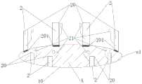
实施例一,如图1所示,所述显微外科手术牵张器,包括基板10和牵拉机构2。基板边缘a1是一个圆,围成的圆形不透光区域内是精索组织放置区A,即手术视野区。通常显微外科手术中,在患者手术区域周围覆盖着手术巾,基板10朝向手术巾的一面设置有固定部11,本实施例中固定部11是一个快拆装结构,具体的采用了双面背胶,设置在靠近两侧的基板边缘a1附近,使用时与手术巾粘贴固定。需要说明的是,本发明中固定部11的作用是将所述显微外科手术牵张器固定在医生需要的位置,与手术巾相固定连接只是一种最为常见的情况。Embodiment 1, as shown in FIG. 1 , the microsurgical stretcher includes a
所述牵拉机构2由牵拉组件21和标识支柱20组成。本实施例中,设置了8个标识支柱20,标识支柱20底部设置有与基板边缘a1相配合的底部快拆装结构,本实施例中所述底部快拆装结构采用与标识支柱20一体成型的夹子,即固定夹201,将每个标识支柱20夹在基板边缘a1上形成固定连接。The pulling
本实施例中牵拉组件21是一根一端固定在标识支柱20柱体上不能动,另一端是自由的并设置有一个弹性小套索的有弹性的细线。将牵拉组件21的自由端绕经手术不触及的组织后,将其拉向标识支柱20,随后将牵拉组件21的自由端在标识支柱20上部缠绕,调整到合适的牵拉固定状态后,牵拉组件21自由端的小套索从标识支柱20顶部套入,完成牵拉到位。In this embodiment, the pulling
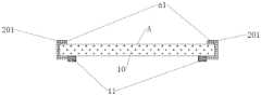
在具体实施例二中,如图2、图3和图4所示,基板10的基板边缘a1有四条,围成一个矩形平板,采用半透光材质制作。由于是用半透光材质制作的,这个基板10同时又起到一个光学弥散片的作用,强光照射到基板10表面会被向各个方向分散反射,有效改善手术视野区的强反光现象,有利于医生观察组织。基板10的底面是朝向手术巾的一面,在基板10的底面两侧设置了固定部11;基板10背离手术巾的一面上就是精索组织放置区A。In the second specific embodiment, as shown in FIG. 2 , FIG. 3 and FIG. 4 , the substrate edge a1 of the
在本实施例中,共设置了6个标识支柱20,3个一组分别对应设置在基板10两侧相对的基板边缘a1附近。标识支柱20底部设置有与基板边缘a1相配合的底部快拆装结构,本实施例中底部快拆装结构也采用与标识支柱20一体成型的夹子,即固定夹201。图4是基板10附近的局部侧面视图,如图所示,固定夹201将两侧的相对基板边缘a1夹住或松开即可实现快拆装。在基板10没有连接标识支柱20的两侧,其侧面是敞开的,实际手术中医生可以方便的将游离出的手术部分从侧面放到基板10内部,也便于操作时从侧面进入手术视野区。本实施例中在每个标识支柱20远离手术部位的上部贴有标签贴202,在标签贴202上可以做标记用来辅助标识被牵拉的组织。当然标签贴202只是本实施例中的一种进行标记的较好做法,没有贴标签202时不同的标识支柱20本身也已经起到了一定区分标识的作用。In this embodiment, a total of six
本实施例中单个牵拉组件21的设计与实施例一相同,不再特别赘述。The design of the single pulling
本发明的实施例三中,与实施例二的区别主要在于牵拉组件21。本实施例中牵拉组件21包括限位部211和牵拉部212,具体参考图5和6所示。图5是牵拉机构2中一对标识支杆20和牵拉组件21相配合的示意图,与实施例二相同,本实施例中也是有6个标识支杆20和相配的6个牵拉组件21;图6示出了一个牵拉组件21中的限位部211与牵拉部212相配合的相关部分;操作本实施例的所述显微外科手术牵张器的过程如图7所示。In the third embodiment of the present invention, the difference from the second embodiment mainly lies in the pulling
牵拉组件21的限位部211将牵拉组件21限定在标识支杆20高度范围内移动,并能够将牵引组件21根据实际手术情况调整到标识支杆20指定高度位置处并固定在标识支杆20上,在本实施例中6个牵拉组件21分别由限位部211固定在6个标识支杆20上不同的高度,手术中能够将需要保留的不同组织牵拉到不同的水平高度上,避免了操作中干涉以及组织间的缠绕。在本实施例中限位部211是一根有一定高度的贯通空心杆,在其下部的快拆端211b处设置有所述第一快拆装结构,用来使得限位部211方便的调整位置和固定到标识支杆20上需要的预设高度位置。在本实施例中快拆端211b处设置有与空心杆一体的滑套夹b,即所述第一快拆装结构,松开滑套夹b上下移动调整限位部211的空心杆在标识支杆20上的位置,调整好后将滑套夹b夹紧则限位部211与标识支杆20固定连接。The limiting
本实施例中牵拉部212采用一根有颜色的弹性细线,牵拉不同组织的牵拉部212是颜色不同的弹性细线。牵拉部212的定位端212d不能与限位部211相脱离。定位端212d是弹性细线一端的绳结扣,使用前将牵拉部212的牵引端212e从限位部211的空心杆底部的开口中伸入并使其从限位部211的空心杆身上的定位孔211a中拉出,定位孔211a的开口大小与牵拉部212的弹性细线的粗细相当,定位端212d的绳结扣无法从定位孔211a中脱出。所以定位端212d的绳结扣和限位部211上开的定位孔211a相配合实现牵拉部212不能从限位部211上脱离。在限位部211高度上的顶端是快锁端211c,本实施例中在快锁端211c设置一个固定夹槽c即所述限位部211上端的所述第二快拆装结构。使用时牵引端212e绕经需要保留的组织后,通过固定夹槽c夹紧与快锁端211c固定连接,达到适当牵拉固定,不影响手术操作但可以明确清晰的看到手术视野中需要操作部位的目的。手术结束,松开快锁端211c的固定夹槽c,放松牵拉部212,让被牵拉组织恢复原位。In this embodiment, the pulling
实施例四与实施例三的区别仅在于基板10。如图8和9所示,图8是基板10附近的局部侧面视图;图9是基板10底部示意图。本实施例中基板10也是采用半透光材质制作的有固定平面的平板。但在基板10的底面,即朝向手术巾的一面,在对应精索组织放置区A区域位置的周围设置有光源102,本实施例中采用条状LED灯带固定在基板10底面相对的两侧边缘;在对应精索组织放置区A区域位置的内部基板10的底面附有一层匀光膜101。手术中如有需要,打开LED光源102,匀光膜101将LED光源102的光均匀照明整个精索组织放置区A,形成良好的补充照明效果,使得手术视野区照明更充足,有利于显微手术中观察找准操作部位,有效支持实现精准治疗,达到理想的显微手术效果。The difference between the fourth embodiment and the third embodiment is only the
上述实施方式为本发明的优选案例,并不用来限制本发明的保护范围。在上述具体实施方式中所描述的各个具体技术特征,在不矛盾的情况下,可以通过任何合适的方式进行组合。为了避免不必要的重复,对各种可能的组合方式本发明不再另行说明。The above embodiments are preferred cases of the present invention, and are not intended to limit the protection scope of the present invention. The various specific technical features described in the above-mentioned specific embodiments may be combined in any suitable manner under the condition of no contradiction. In order to avoid unnecessary repetition, various possible combinations are not described in the present invention.
Claims (12)
Translated fromChinesePriority Applications (1)
| Application Number | Priority Date | Filing Date | Title |
|---|---|---|---|
| CN202010271170.9ACN111436983A (en) | 2020-04-08 | 2020-04-08 | Microsurgery operation tractive ware |
Applications Claiming Priority (1)
| Application Number | Priority Date | Filing Date | Title |
|---|---|---|---|
| CN202010271170.9ACN111436983A (en) | 2020-04-08 | 2020-04-08 | Microsurgery operation tractive ware |
Publications (1)
| Publication Number | Publication Date |
|---|---|
| CN111436983Atrue CN111436983A (en) | 2020-07-24 |
Family
ID=71652816
Family Applications (1)
| Application Number | Title | Priority Date | Filing Date |
|---|---|---|---|
| CN202010271170.9APendingCN111436983A (en) | 2020-04-08 | 2020-04-08 | Microsurgery operation tractive ware |
Country Status (1)
| Country | Link |
|---|---|
| CN (1) | CN111436983A (en) |
Citations (21)
| Publication number | Priority date | Publication date | Assignee | Title |
|---|---|---|---|---|
| DE3234875A1 (en)* | 1982-09-21 | 1984-03-22 | S & T Marketing AG, 8212 Neuhausen am Rheinfall | Device for preparing an operating area in surgery, especially in microsurgery |
| EP0143124A1 (en)* | 1983-10-12 | 1985-06-05 | Roger Q. Estes | Surgical retractor elements and assembly |
| CN2278438Y (en)* | 1997-03-07 | 1998-04-15 | 河南省人民医院 | Micronervus retractor |
| CN2287905Y (en)* | 1996-03-29 | 1998-08-19 | 刘飞龙 | Anorectal retractor |
| AU2002300141A1 (en)* | 1997-07-18 | 2002-12-12 | Alf Petersvik | Retractor System Used in Surgical Operations |
| US20060253109A1 (en)* | 2006-02-08 | 2006-11-09 | David Chu | Surgical robotic helping hand system |
| CN101015466A (en)* | 2007-03-01 | 2007-08-15 | 王俊 | Adjustable abdomen wall retractor |
| CN102283719A (en)* | 2011-07-07 | 2011-12-21 | 深圳市瑞沃德生命科技有限公司 | Multifunctional fine animal surgery positioning device |
| KR20140091985A (en)* | 2013-01-14 | 2014-07-23 | 전북대학교산학협력단 | varicocelectomy Surgical instrument |
| CN204581368U (en)* | 2015-02-16 | 2015-08-26 | 中国人民解放军第二军医大学 | A kind of Micronervus retractor |
| CN205163138U (en)* | 2015-12-17 | 2016-04-20 | 郑州人民医院 | Medical wire retractor |
| CN205548605U (en)* | 2016-03-24 | 2016-09-07 | 徐州市肿瘤医院 | Thermal -insulated drag hook of little incision operation |
| CN106859713A (en)* | 2017-03-10 | 2017-06-20 | 江苏省中医药研究院 | A kind of modified vaginal tractor |
| CN107822677A (en)* | 2017-11-21 | 2018-03-23 | 浙江大学 | A kind of operation on vagina self-retaining retractor |
| CN207370730U (en)* | 2017-01-20 | 2018-05-18 | 绍兴市人民医院 | A kind of laminectomy retractor of anterior cervical operation |
| CN207532407U (en)* | 2017-03-31 | 2018-06-26 | 江苏大学附属医院 | An abdominal surgical incision exposure and fixation device |
| CN208464153U (en)* | 2017-07-10 | 2019-02-05 | 上海市同济医院 | A kind of spermatic duct anastomosing operation drawing clamping external member |
| CN209074715U (en)* | 2017-11-21 | 2019-07-09 | 浙江大学 | A kind of self-retaining retractor for operation on vagina |
| CN209252971U (en)* | 2018-05-30 | 2019-08-16 | 易小春 | A kind of operative incision pulling device |
| CN110338861A (en)* | 2019-08-03 | 2019-10-18 | 张楠 | An auxiliary surgical device and surgical hook for providing surgical background light source |
| CN212438710U (en)* | 2020-04-08 | 2021-02-02 | 苏州大学附属第二医院 | A microsurgical stretcher |
- 2020
- 2020-04-08CNCN202010271170.9Apatent/CN111436983A/enactivePending
Patent Citations (21)
| Publication number | Priority date | Publication date | Assignee | Title |
|---|---|---|---|---|
| DE3234875A1 (en)* | 1982-09-21 | 1984-03-22 | S & T Marketing AG, 8212 Neuhausen am Rheinfall | Device for preparing an operating area in surgery, especially in microsurgery |
| EP0143124A1 (en)* | 1983-10-12 | 1985-06-05 | Roger Q. Estes | Surgical retractor elements and assembly |
| CN2287905Y (en)* | 1996-03-29 | 1998-08-19 | 刘飞龙 | Anorectal retractor |
| CN2278438Y (en)* | 1997-03-07 | 1998-04-15 | 河南省人民医院 | Micronervus retractor |
| AU2002300141A1 (en)* | 1997-07-18 | 2002-12-12 | Alf Petersvik | Retractor System Used in Surgical Operations |
| US20060253109A1 (en)* | 2006-02-08 | 2006-11-09 | David Chu | Surgical robotic helping hand system |
| CN101015466A (en)* | 2007-03-01 | 2007-08-15 | 王俊 | Adjustable abdomen wall retractor |
| CN102283719A (en)* | 2011-07-07 | 2011-12-21 | 深圳市瑞沃德生命科技有限公司 | Multifunctional fine animal surgery positioning device |
| KR20140091985A (en)* | 2013-01-14 | 2014-07-23 | 전북대학교산학협력단 | varicocelectomy Surgical instrument |
| CN204581368U (en)* | 2015-02-16 | 2015-08-26 | 中国人民解放军第二军医大学 | A kind of Micronervus retractor |
| CN205163138U (en)* | 2015-12-17 | 2016-04-20 | 郑州人民医院 | Medical wire retractor |
| CN205548605U (en)* | 2016-03-24 | 2016-09-07 | 徐州市肿瘤医院 | Thermal -insulated drag hook of little incision operation |
| CN207370730U (en)* | 2017-01-20 | 2018-05-18 | 绍兴市人民医院 | A kind of laminectomy retractor of anterior cervical operation |
| CN106859713A (en)* | 2017-03-10 | 2017-06-20 | 江苏省中医药研究院 | A kind of modified vaginal tractor |
| CN207532407U (en)* | 2017-03-31 | 2018-06-26 | 江苏大学附属医院 | An abdominal surgical incision exposure and fixation device |
| CN208464153U (en)* | 2017-07-10 | 2019-02-05 | 上海市同济医院 | A kind of spermatic duct anastomosing operation drawing clamping external member |
| CN107822677A (en)* | 2017-11-21 | 2018-03-23 | 浙江大学 | A kind of operation on vagina self-retaining retractor |
| CN209074715U (en)* | 2017-11-21 | 2019-07-09 | 浙江大学 | A kind of self-retaining retractor for operation on vagina |
| CN209252971U (en)* | 2018-05-30 | 2019-08-16 | 易小春 | A kind of operative incision pulling device |
| CN110338861A (en)* | 2019-08-03 | 2019-10-18 | 张楠 | An auxiliary surgical device and surgical hook for providing surgical background light source |
| CN212438710U (en)* | 2020-04-08 | 2021-02-02 | 苏州大学附属第二医院 | A microsurgical stretcher |
Similar Documents
| Publication | Publication Date | Title |
|---|---|---|
| JP3232938U (en) | Tow device and tow ring for tow device | |
| Pool et al. | The dissecting microscope for intracranial vascular surgery | |
| JPH07501247A (en) | ocular fixation device | |
| JPH06169880A (en) | Glare removing apparatus | |
| NO312054B1 (en) | Wound latch system for use in surgical operations | |
| US6308710B1 (en) | Scrotal drape and support | |
| CN204951048U (en) | Hepatic portal blood flow block device for laparoscopic surgery | |
| Faugeron et al. | Approches de la prison | |
| JP2003530943A (en) | Suction type retractor to be attached to internal organs | |
| CN212438710U (en) | A microsurgical stretcher | |
| CN111436983A (en) | Microsurgery operation tractive ware | |
| Pannu | Incidence and treatment of wrinkled corneal flap following LASIK | |
| CN217772402U (en) | Perineum visual field exposing device | |
| Jacobson II | Microsurgery | |
| Troutman | The operating microscope in ophthalmic surgery | |
| Roohi | Tips and Tricks in Microvascular | |
| Chang | Principles, techniques and applications in microsurgery | |
| CN218979023U (en) | Auxiliary device is sewed up to sacrospinous ligament | |
| JPH0741447Y2 (en) | Medical instruments for arterial surgery | |
| CN218975027U (en) | Esophagus simulation training device | |
| CN217696655U (en) | Fixing clamp for drawing hepatic round ligament to expose liver | |
| Wacksman | Repair of hypospadias using new mouth-controlled microscope | |
| RU2541336C2 (en) | Surgical suprascrotal approach for surgical management of scrotal pathology | |
| JPH08266547A (en) | Annular inciser for pseudophimosis root | |
| Duan et al. | Basic Techniques of Micro-Orthopedics |
Legal Events
| Date | Code | Title | Description |
|---|---|---|---|
| PB01 | Publication | ||
| PB01 | Publication | ||
| SE01 | Entry into force of request for substantive examination | ||
| SE01 | Entry into force of request for substantive examination |