CN111435261B - Fixing mechanism and related electronic equipment - Google Patents
Fixing mechanism and related electronic equipmentDownload PDFInfo
- Publication number
- CN111435261B CN111435261BCN201910026367.3ACN201910026367ACN111435261BCN 111435261 BCN111435261 BCN 111435261BCN 201910026367 ACN201910026367 ACN 201910026367ACN 111435261 BCN111435261 BCN 111435261B
- Authority
- CN
- China
- Prior art keywords
- actuator
- electronic component
- detachable frame
- housing
- fixing mechanism
- Prior art date
- Legal status (The legal status is an assumption and is not a legal conclusion. Google has not performed a legal analysis and makes no representation as to the accuracy of the status listed.)
- Active
Links
Images


Classifications
- H—ELECTRICITY
- H05—ELECTRIC TECHNIQUES NOT OTHERWISE PROVIDED FOR
- H05K—PRINTED CIRCUITS; CASINGS OR CONSTRUCTIONAL DETAILS OF ELECTRIC APPARATUS; MANUFACTURE OF ASSEMBLAGES OF ELECTRICAL COMPONENTS
- H05K5/00—Casings, cabinets or drawers for electric apparatus
- H05K5/10—Casings, cabinets or drawers for electric apparatus comprising several parts forming a closed casing
- H05K5/15—Casings, cabinets or drawers for electric apparatus comprising several parts forming a closed casing assembled by resilient members
- G—PHYSICS
- G06—COMPUTING OR CALCULATING; COUNTING
- G06F—ELECTRIC DIGITAL DATA PROCESSING
- G06F1/00—Details not covered by groups G06F3/00 - G06F13/00 and G06F21/00
- G06F1/16—Constructional details or arrangements
- G06F1/18—Packaging or power distribution
- G06F1/183—Internal mounting support structures, e.g. for printed circuit boards, internal connecting means
- H—ELECTRICITY
- H05—ELECTRIC TECHNIQUES NOT OTHERWISE PROVIDED FOR
- H05K—PRINTED CIRCUITS; CASINGS OR CONSTRUCTIONAL DETAILS OF ELECTRIC APPARATUS; MANUFACTURE OF ASSEMBLAGES OF ELECTRICAL COMPONENTS
- H05K7/00—Constructional details common to different types of electric apparatus
- H05K7/14—Mounting supporting structure in casing or on frame or rack
- H05K7/1485—Servers; Data center rooms, e.g. 19-inch computer racks
- H05K7/1487—Blade assemblies, e.g. blade cases or inner arrangements within a blade
- G—PHYSICS
- G06—COMPUTING OR CALCULATING; COUNTING
- G06F—ELECTRIC DIGITAL DATA PROCESSING
- G06F1/00—Details not covered by groups G06F3/00 - G06F13/00 and G06F21/00
- G06F1/16—Constructional details or arrangements
- G06F1/18—Packaging or power distribution
- G06F1/181—Enclosures
- G—PHYSICS
- G06—COMPUTING OR CALCULATING; COUNTING
- G06F—ELECTRIC DIGITAL DATA PROCESSING
- G06F1/00—Details not covered by groups G06F3/00 - G06F13/00 and G06F21/00
- G06F1/16—Constructional details or arrangements
- G06F1/18—Packaging or power distribution
- G06F1/183—Internal mounting support structures, e.g. for printed circuit boards, internal connecting means
- G06F1/185—Mounting of expansion boards
- H—ELECTRICITY
- H05—ELECTRIC TECHNIQUES NOT OTHERWISE PROVIDED FOR
- H05K—PRINTED CIRCUITS; CASINGS OR CONSTRUCTIONAL DETAILS OF ELECTRIC APPARATUS; MANUFACTURE OF ASSEMBLAGES OF ELECTRICAL COMPONENTS
- H05K7/00—Constructional details common to different types of electric apparatus
- H05K7/14—Mounting supporting structure in casing or on frame or rack
- H05K7/1401—Mounting supporting structure in casing or on frame or rack comprising clamping or extracting means
- H05K7/1402—Mounting supporting structure in casing or on frame or rack comprising clamping or extracting means for securing or extracting printed circuit boards
- H05K7/1405—Mounting supporting structure in casing or on frame or rack comprising clamping or extracting means for securing or extracting printed circuit boards by clips or resilient members, e.g. hooks
Landscapes
- Engineering & Computer Science (AREA)
- Theoretical Computer Science (AREA)
- Computer Hardware Design (AREA)
- General Engineering & Computer Science (AREA)
- Power Engineering (AREA)
- Human Computer Interaction (AREA)
- Physics & Mathematics (AREA)
- General Physics & Mathematics (AREA)
- Microelectronics & Electronic Packaging (AREA)
- Casings For Electric Apparatus (AREA)
- Mounting Components In General For Electric Apparatus (AREA)
Abstract
Translated fromChinese
Description
Translated fromChinese技术领域technical field
本发明提供一种固定机构及其相关电子设备,特别涉及一种可提供稳定组装与快速拆卸、并具有快拆功能的固定机构及其相关电子设备。The invention provides a fixing mechanism and its related electronic equipment, and in particular relates to a fixing mechanism and its related electronic equipment which can provide stable assembly and quick disassembly, and have a quick disassembly function.
背景技术Background technique
服务器设备里通常会设置多个电子组件,例如硬盘、网络卡、显示适配器或扩展卡等等。以硬盘为例,传统的电子组件安装方式是在硬盘的边缘锁上一个具有锁孔的桥接件,硬盘装入服务器设备内的固定座时,将外部固定元件(例如螺钉、螺栓)穿入桥接件的锁孔、并插入固定座的螺纹结构,然后再用外部工具(例如螺丝起子或扳手)将固定元件确实锁入螺纹结构,以完成硬盘的组装。如要拆除硬盘,则需使用外部工具将固定元件自螺纹结构松开,然后从桥接件的锁孔拔除固定元件,才能分离硬盘与固定座。由此可知,传统的电子组件安装方式操作复杂繁琐,无法快速且轻易进行拆装。Multiple electronic components, such as hard disks, network cards, display adapters or expansion cards, etc., are usually installed in the server equipment. Taking the hard disk as an example, the traditional installation method of electronic components is to lock a bridge with a keyhole on the edge of the hard disk. The locking hole of the component and inserted into the threaded structure of the fixing seat, and then use an external tool (such as a screwdriver or a wrench) to lock the fixing element into the threaded structure to complete the assembly of the hard disk. If the hard disk needs to be removed, it is necessary to use an external tool to loosen the fixing element from the threaded structure, and then pull out the fixing element from the locking hole of the bridge piece to separate the hard disk and the fixing seat. It can be seen that the traditional installation method of electronic components is complex and cumbersome, and cannot be disassembled quickly and easily.
因此,需要提供一种固定机构及其相关电子设备来解决上述问题。Therefore, it is necessary to provide a fixing mechanism and its related electronic equipment to solve the above problems.
发明内容Contents of the invention
本发明提供一种可提供稳定组装与快速拆卸、并具有快拆功能的固定机构及其相关电子设备,以解决上述的问题。The present invention provides a fastening mechanism capable of stable assembly and quick disassembly, and has a quick disassembly function, and its related electronic equipment, so as to solve the above-mentioned problems.
本发明的权利要求书公开一种固定机构,该固定机构用来将一第一电子组件固定在具有一第二结合件的一第二电子组件,该固定机构包括一可拆式架体、一第一结合件以及一致动件;该第一电子组件组装于该可拆式架体;该第一结合件设置在该可拆式架体,对应于该第二结合件;该致动件活动设置在该可拆式架体以在一第一位置及一第二位置之间移动,该致动件在该第一位置时,该第一结合件未卡合于该第二结合件,该致动件在该第二位置时,该第一结合件卡合于该第二结合件。The claims of the present invention disclose a fixing mechanism, which is used to fix a first electronic component to a second electronic component having a second joint, and the fixing mechanism includes a detachable frame body, a A first coupling part and an actuating part; the first electronic component is assembled on the detachable frame body; the first coupling part is arranged on the detachable frame body, corresponding to the second coupling part; the actuating part is movable It is arranged on the detachable frame body to move between a first position and a second position. When the actuator is in the first position, the first coupling part is not engaged with the second coupling part, and the When the actuating member is at the second position, the first coupling part is engaged with the second coupling part.
本发明的权利要求书还公开该第一结合件具有可相对弹性变形的至少二结合部,该第二结合件为设置在该第二电子组件的一破孔部,该致动件的一插销插入该至少二结合部之间,使该至少二结合部紧扣该破孔部,该插销置于该至少二结合部之间,以避免该至少二结合部弹性变形。The claims of the present invention also disclose that the first coupling part has at least two coupling parts that can be relatively elastically deformed, the second coupling part is provided in a hole part of the second electronic component, and a pin of the actuating part inserting between the at least two combining parts so that the at least two combining parts are fastened to the hole, and the pin is placed between the at least two combining parts to avoid elastic deformation of the at least two combining parts.
本发明的权利要求书还公开该可拆式架体还具有二卡勾部以及一开口,该致动件穿入该开口以容置在该可拆式架体内,该致动件具有一本体以及一开槽部,该本体的一宽度大于该二卡勾部的一间距,该开槽部设置在该本体的一侧缘,该本体经由该开槽部装入该二卡勾部之间。The claims of the present invention also disclose that the detachable frame body also has two hook portions and an opening, and the actuating member passes through the opening to be accommodated in the detachable frame body, and the actuating member has a body and a slotted part, a width of the main body is greater than a distance between the two hook parts, the slotted part is arranged on one side edge of the main body, and the main body is inserted between the two hooked parts through the slotted part .
本发明的权利要求书还公开该可拆式架体还具有二第一扣接部,该致动件具有一本体以及一第二扣接部,该第二扣接部的一端连接该本体,该第二扣接部的另一端以可分离方式选择性卡合该二第一扣接部的其中之一。The claims of the present invention also disclose that the detachable frame body further has two first fastening parts, the actuator has a body and a second fastening part, and one end of the second fastening part is connected to the main body. The other end of the second fastening portion is selectively engaged with one of the two first fastening portions in a detachable manner.
本发明的权利要求书还公开该可拆式架体还具有一第一闩扣部,该致动件具有一本体以及一第二闩扣部,该第二闩扣部的一端连接该本体,该第二闩扣部的另一端卡合该第一闩扣部,将该致动件定位在该可拆式架体的一特定位置。The claims of the present invention also disclose that the detachable frame body further has a first latch portion, the actuator has a body and a second latch portion, one end of the second latch portion is connected to the body, The other end of the second latch part is engaged with the first latch part, and the actuator is positioned at a specific position of the detachable frame.
本发明的权利要求书还公开该可拆式架体还具有一第一止抵部,该致动件具有一本体以及一第二止抵部,该第二止抵部设置在该本体的一底端,用来止抵该第一止抵部,以限制该致动件相对于该可拆式架体的移动。The claims of the present invention also disclose that the detachable frame body also has a first stop portion, the actuator has a body and a second stop portion, and the second stop portion is arranged on a side of the body. The bottom end is used to abut against the first abutting portion to limit the movement of the actuator relative to the detachable frame.
本发明的权利要求书还公开该可拆式架体具有弯折连接的一第一板部以及一第二板部,该第一电子组件经由该第一板部组装于该可拆式架体,该第二板部设置具有一插槽的一电路板,该第一电子组件组装于该第一板部且插接该插槽。The claims of the present invention also disclose that the detachable frame body has a first plate portion and a second plate portion that are bent and connected, and the first electronic component is assembled on the detachable frame body through the first plate portion , the second board part is provided with a circuit board with a slot, the first electronic component is assembled on the first board part and plugged into the slot.
本发明的权利要求书还公开该可拆式架体还具有至少一个导引部、一突出部以及一阻挡部,该导引部可滑动地止抵一壳体的一支撑部以组装于该壳体上,该突出部可活动地插入一壳体的一穿孔结构以将该可拆式架体定位于该壳体,该阻挡部用来抵接一壳体的一束缚部以限制该可拆式架体相对该壳体的移动。The claims of the present invention also disclose that the detachable frame body further has at least one guide part, a protruding part and a blocking part, and the guide part is slidably stopped against a support part of a housing to be assembled on the On the housing, the protruding part can be movably inserted into a perforation structure of a housing to position the detachable frame on the housing, and the blocking part is used to abut against a binding part of a housing to limit the movable The movement of the detachable frame relative to the housing.
本发明的权利要求书还公开该致动件在该第二位置时驱动该第一结合件以紧配方式卡合该第二结合件,该致动件具有一本体以及一握持部,该握持部弯折连接该本体,该握持部受一外力驱动可使该致动件在该第一位置与该第二位置之间切换。The claims of the present invention also disclose that when the actuator is in the second position, the first coupling is driven to engage the second coupling in a tightly fitting manner. The actuator has a body and a gripping portion. The grip part is bent and connected to the body, and the grip part is driven by an external force to switch the actuator between the first position and the second position.
本发明的权利要求书还公开该固定机构还包括一限位件,活动设置在该可拆式架体,该限位件止挡于该可拆式架体旁,以限制该第一电子组件相对于该可拆式架体的移动。The claims of the present invention also disclose that the fixing mechanism further includes a limiter, which is movably arranged on the detachable frame, and the limiter is stopped by the detachable frame to limit the first electronic component Movement relative to the detachable frame.
本发明的权利要求书还公开一种电子设备,该电子设备包括一壳体、一第一电子组件、一第二电子组件以及一固定机构;该第二电子组件设置在该壳体内,该第二电子组件具有一第二结合件;该固定机构用来将该第一电子组件固定在该第二电子组件,该固定机构包括一可拆式架体、一第一结合件以及一致动件;该第一电子组件组装于该可拆式架体;该第一结合件设置在该可拆式架体,对应于该第二结合件;该致动件活动设置在该可拆式架体以在一第一位置及一第二位置之间移动,该致动件在该第一位置时,该第一结合件未卡合于该第二结合件,该致动件在该第二位置时,该第一结合件卡合于该第二结合件。The claims of the present invention also disclose an electronic device, which includes a housing, a first electronic component, a second electronic component and a fixing mechanism; the second electronic component is arranged in the housing, and the first The second electronic component has a second coupling part; the fixing mechanism is used to fix the first electronic component to the second electronic component, and the fixing mechanism includes a detachable frame body, a first coupling part and an actuating part; The first electronic component is assembled on the detachable frame; the first coupling part is arranged on the detachable frame, corresponding to the second coupling part; the actuator is movably arranged on the detachable frame to Move between a first position and a second position, when the actuator is in the first position, the first joint is not engaged with the second joint, and when the actuator is in the second position , the first coupling part is engaged with the second coupling part.
本发明的权利要求书还公开一种电子设备,其包括一壳体、一第一电子组件、一第二电子组件以及一固定机构。该第二电子组件设置在该壳体内,且具有一第二结合件。该固定机构用来将该第一电子组件固定在该第二电子组件。该固定机构包括一可拆式架体、一第一结合件以及一致动件。该第一电子组件组装于该可拆式架体。该第一结合件设置在该可拆式架体,且对应于该第二结合件。该致动件活动设置在该可拆式架体以在一第一位置及一第二位置之间移动。The claims of the present invention also disclose an electronic device, which includes a casing, a first electronic component, a second electronic component and a fixing mechanism. The second electronic component is arranged in the housing and has a second combination part. The fixing mechanism is used to fix the first electronic component to the second electronic component. The fixing mechanism includes a detachable frame body, a first combining part and an actuating part. The first electronic component is assembled on the detachable frame. The first combination part is arranged on the detachable frame body and corresponds to the second combination part. The actuator is movably arranged on the detachable frame to move between a first position and a second position.
本发明的权利要求书还公开该电子设备还包括一吸振元件以及一附属构件,该吸振元件具有一夹持部以及一拘束部,该第一电子组件具有一桥接部,该桥接部插入该夹持部以限制至少一方向的移动,该拘束部以弹性变形方式拘束该桥接部相对于该夹持部的该移动,该附属构件设置在该壳体内,该吸振元件以可拆卸方式卡合于该附属构件的至少一约束部。The claims of the present invention also disclose that the electronic device further includes a shock-absorbing element and an accessory component, the shock-absorbing element has a clamping portion and a constraining portion, the first electronic component has a bridging portion, and the bridging portion is inserted into the clip holding part to restrict movement in at least one direction, the constraining part constrains the movement of the bridging part relative to the clamping part in an elastic deformation manner, the accessory member is arranged in the housing, and the shock-absorbing element is detachably engaged with the At least one constraining portion of the accessory component.
本发明的电子设备将第二电子组件设置在壳体内,第一电子组件先组装于固定机构,再随固定机构设置进壳体以电连接第二电子组件。固定机构具有通用设计,可安装多种规格的第一电子组件。第一电子组件为图形处理单元时,固定机构的可拆式架体可承载单片图形处理单元;第一电子组件为其他接口卡时,可拆式架体可设计为单层或多层,用来承载单片或多片接口卡。可拆式架体的机构高度改变时,致动件的长度亦可相应调整。本发明的固定机构具有结构简单与操作容易的优点,电子设备利用固定机构组装第一电子组件与第二电子组件,可有效节约壳体内部空间;此外,固定机构可承载多种规格的电子组件,大幅提升电子设备的市场竞争力。In the electronic device of the present invention, the second electronic component is arranged in the housing, and the first electronic component is first assembled in the fixing mechanism, and then installed into the housing along with the fixing mechanism to electrically connect the second electronic component. The fixing mechanism has a universal design and can be installed with various specifications of the first electronic component. When the first electronic component is a graphics processing unit, the detachable frame of the fixing mechanism can carry a single graphics processing unit; when the first electronic component is another interface card, the detachable frame can be designed as a single layer or multiple layers, Used to carry single or multiple interface cards. When the mechanism height of the detachable frame changes, the length of the actuator can also be adjusted accordingly. The fixing mechanism of the present invention has the advantages of simple structure and easy operation. The electronic device uses the fixing mechanism to assemble the first electronic component and the second electronic component, which can effectively save the internal space of the housing; in addition, the fixing mechanism can carry electronic components of various specifications , greatly enhance the market competitiveness of electronic equipment.
附图说明Description of drawings
图1为本发明实施例的电子设备的组装图。FIG. 1 is an assembly diagram of an electronic device according to an embodiment of the present invention.
图2为本发明实施例的电子设备的元件分解图。FIG. 2 is an exploded view of components of an electronic device according to an embodiment of the present invention.
图3为本发明实施例的第一电子组件与吸振元件的组装示意图。FIG. 3 is a schematic diagram of the assembly of the first electronic component and the vibration-absorbing element according to the embodiment of the present invention.
图4为本发明实施例的吸振元件与附属构件的组装示意图。FIG. 4 is a schematic diagram of the assembly of the vibration-absorbing element and the accessory components according to the embodiment of the present invention.
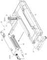
图5与图6为本发明实施例的固定机构在不同视角的组件分解图。FIG. 5 and FIG. 6 are exploded views of the fixing mechanism in different viewing angles according to the embodiment of the present invention.
图7为本发明实施例的固定机构与第一电子组件的组合示意图。FIG. 7 is a schematic diagram of the combination of the fixing mechanism and the first electronic component according to the embodiment of the present invention.
图8与图9为本发明实施例的固定机构与壳体在不同视角的组合示意图。FIG. 8 and FIG. 9 are combined diagrams of the fixing mechanism and the housing in different viewing angles according to the embodiment of the present invention.
图10与图11为本发明实施例的固定机构在不同操作阶段的示意图。FIG. 10 and FIG. 11 are schematic diagrams of different operation stages of the fixing mechanism according to the embodiment of the present invention.
图12为本发明实施例的固定机构的部分放大示意图。Fig. 12 is a partially enlarged schematic view of the fixing mechanism of the embodiment of the present invention.
主要组件符号说明:Description of main component symbols:
10 电子设备 62 电路板10
12 壳体 64 本体12
14 第一电子组件 66 开槽部14
16 第二电子组件 68 第二扣接部16 Second
18 吸振元件 681 第二扣接部的一端18 One end of the shock-absorbing
20 附属构件 682 第二扣接部的另一端20
22 固定机构 70 第二闩扣部22
24 夹持部 701 第二闩扣部的一端24 Clamp
26 拘束部 702 第二闩扣部的另一端26 Restricting
28 桥接部 72 第二止抵部28 Bridge 72 Second stop
29 止挡部 74 握持部29 Stop 74 Grip
30 约束部 76 开口30
301 止挡肋 78 支撑部301
302 定位销 80 推抵结构302
32 破孔 82 束缚部32
34 可拆式架体 84 承架34
36 限位件 86 穿孔结构36 Limiting
37 转轴 88 结合部37
38 第一结合件 90 第二结合件38 First joint 90 Second joint
40 致动件 92 插销40
42 第一板部 94 延伸结构42
44 第二板部 96 斜导结构44
46 卡勾部 D1 第一方向46 Hook part D1 First direction
48 第一扣接部 D2 第二方向48 First fastening part D2 Second direction
50 第一闩扣部 D3 第三方向50 First latch part D3 Third direction
52 第一止抵部 W1 本体宽度52 First stop W1 Body width
54 导引部 G1 卡勾部间距54 Guide part G1 hook part spacing
56 突出部 I1 延伸结构的间距56 Protrusion I1 Spacing for extensions
58 阻挡部 I2 斜导结构的间距58 Spacing of barrier I2 inclined guide structure
60 插槽 A1 第二结合件的孔径60 Slot A1 Bore diameter of second coupling
59 卡勾59 hook
具体实施方式detailed description
请参阅图1与图2,图1为本发明实施例的电子设备10的组装图,图2为本发明实施例的电子设备10的元件分解图。电子设备10可包含有壳体12、第一电子组件14、第二电子组件16、吸振元件18、附属构件20以及固定机构22。吸振元件18属于选择性配件。若第一电子组件14的尺寸偏小,以致第一电子组件14组装于壳体12内时无法触及附属构件20,便可将吸振元件18设置在第一电子组件14和附属构件20之间,避免第一电子组件14过度晃动而影响其效能。固定机构22用来将第一电子组件14固定在第二电子组件16;例如第一电子组件14先结合固定机构22,然后再固定到第二电子组件16上。使用者不须额外工具便能通过固定机构22组装或拆卸第一电子组件14及第二电子组件16,使电子设备10具有快拆功能。Please refer to FIG. 1 and FIG. 2 , FIG. 1 is an assembly diagram of an
请参阅图3与图4,图3为本发明实施例的第一电子组件14与吸振元件18的组装示意图,图4为本发明实施例的吸振元件18与附属构件20的组装示意图。如图3所示,吸振元件18可具有一个或多个的夹持部24与拘束部26,第一电子组件14可具有桥接部28。夹持部24以其双片结构上下夹持桥接部28,拘束部26则扣住桥接部28;然而夹持部24与拘束部26的形状并不限于前述公开实施形式。桥接部28插入夹持部24后,可限制第一电子组件14在第一方向D1的移动;拘束部26以弹性变形方式拘束桥接部28,可限制第一电子组件14在第二方向D2的移动;吸振元件18还有数个止挡部29,挡住第一电子组件14的左右两侧,限制第一电子组件14在第三方向D3的移动。Please refer to FIG. 3 and FIG. 4 . FIG. 3 is an assembly diagram of the first
关于吸振元件18与附属构件20的组装与拆卸,如图4所示,附属构件20可具有多个约束部30,分设在多处以卡住吸振元件18的多个端角。约束部30可包含止挡肋301以及定位销302。止挡肋301与定位销302的数量、位置和相对关系不限于此实施例所示,依设计需求而定。定位销302穿过吸振元件18的破孔32,止挡肋301围绕止挡在吸振元件18的端角侧边,只要往上抬高吸振元件18就能脱离止挡肋301及定位销302的约束,意即吸振元件18以可拆卸方式卡合于附属构件20的约束部30。Regarding the assembly and disassembly of the vibration-absorbing
请参阅图5与图6,图5与图6为本发明实施例的固定机构22在不同视角的元件分解图。固定机构22可包含可拆式架体34、限位件36、第一结合件38以及致动件40。限位件36利用转轴37可旋转地设置在可拆式架体34。第一结合件38安装在可拆式架体34,致动件40可活动地设置在可拆式架体34且能驱使第一结合件38产生弹性变形的作动。可拆式架体34可具有第一板部42、第二板部44、卡勾部46、第一扣接部48、第一闩扣部50、第一止抵部52、导引部54、突出部56以及阻挡部58。第一板部42与第二板部44彼此弯折连结在一起。限位件36可旋转地设置于第一板部42的旁侧,卡勾部46则设置在第二板部44。第一扣接部48与第一闩扣部50亦配合卡勾部46而设置在第二板部44。第一结合件38经由第一止抵部52安装于可拆式架体34上,第一止抵部52用来承载致动件40,使致动件40的插销92能通过第一止抵部52的孔洞接触第一结合件38。导引部54与阻挡部58较佳位于第一板部42的两相对侧。阻挡部58藉由卡勾59固定在第一板部42。突出部56则位于可拆式架体34的底面。Please refer to FIG. 5 and FIG. 6 . FIG. 5 and FIG. 6 are exploded views of the
致动件40可具有本体64、开槽部66、第二扣接部68、第二闩扣部70、第二止抵部72以及握持部74。开槽部66设置在本体64的侧缘。本体64的宽度W1大于两个相对卡勾部46的自由端的间距G1,因此可利用开槽部66对齐卡勾部46的方式,使致动件40能装入卡勾部46的拘束范围内,意即致动件40可安装在卡勾部46与第二板部44的板面之间。在本发明的实施形式中,第二扣接部68属于弹臂元件,然而实际应用当不限于此。第二扣接部68的一端681连接本体64,第二扣接部68的另一端682以可分离方式选择性卡合两个第一扣接部48的其中之一;致动件40在抬高与按压的状态时,第二扣接部68会分别进入上方及下方的第一扣接部48,从而提供组装手感。在其它可能的变化实施形式中,可拆式架体34可具有三个或三个以上第一扣接部48,致动件40相对可拆式架体34垂直移动过程中,第二扣接部68可依序卡合到对应的第一扣接部48,用来提示致动件40已切换到特定高度。The
一般来说,第二闩扣部70亦属于弹臂元件。第二闩扣部70的一端701连接本体64,第二闩扣部70的另一端702可根据致动件40与可拆式架体34的相对位置选择性卡合第一闩扣部50,将致动件40定位在可拆式架体34上的特定位置。致动件40因第一闩扣部50与第二闩扣部70的卡合,不致因外力碰撞而掉出可拆式架体34外。第二止抵部72设置在本体64的底端,插销92设置于第二止抵部72。在致动件40被下移时,第二止抵部72可用来抵接第一止抵部52,限制致动件40相对可拆式架体34的移动,避免过压。握持部74弯折地连接至本体64。握持部74可经由可拆式架体34的开口76显露于外。致动件40穿入开口76以容置在可拆式架体34内,可有效节省固定机构22的内部空间配置。使用者手指可穿过开口76去按压或拉抬握持部74,驱使致动件40相对于可拆式架体34产生上升或下降的位置变化。Generally speaking, the
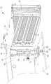
请参阅图7至图9,图7为本发明实施例的固定机构22与第一电子组件14的组合示意图,图8与图9为本发明实施例的固定机构22与壳体12在不同视角的组合示意图。此实施例中,可拆式架体34的第二板部44可设置具有插槽60的电路板62。欲组装固定机构22与第一电子组件14,首先旋转限位件36以从闭合位置(如图7所示实线图案)切换到开启位置(如图7所示虚线图案)。接着,第一电子组件14沿着水平方向侧向移动,经由第一板部42的滑槽或导引槽装入可拆式架体34内,直到接近电路板62并插接插槽60。电路板62还插接于第二电子组件16,故第一电子组件14可经由电路板62建立连接于第二电子组件16的信号传输通道。最后,限位件36从开启位置(如图7所示虚线图案)切换回闭合位置(如图7所示实线图案)以止挡在第一电子组件14外侧,即能限制第一电子组件14相对于第一板部42的移动。Please refer to FIG. 7 to FIG. 9. FIG. 7 is a schematic diagram of the combination of the
如图8与图9所示,壳体12可具有支撑部78,且支撑部78可由数个推抵结构80构成,分别对应可拆式架体34的数个导引部54。可拆式架体34相对壳体12移动时,导引部54可沿着推抵结构80滑移,有效限制可拆式架体34的行进方向,确保可拆式架体34能组装到壳体12上的正确位置。壳体12还可具有束缚部82,束缚部82可为L形的单弯折结构。束缚部82的一端固定在壳体12的承架84上,束缚部82的另一端相对弯折、并可介于限位件36与阻挡部58之间。阻挡部58可滑动地止抵束缚部82,限制可拆式架体34在特定方向相对壳体12的移动。可拆式架体34的突出部56则以可分离方式插入壳体12的穿孔结构86,以限定可拆式架体34在壳体12上的组装位置。欲组装固定机构22与壳体12,利用导引部54与支撑部78的组合、以及阻挡部58与束缚部82的组合提供导引,使突出部56能精准插入穿孔结构86,达到定位目的。As shown in FIG. 8 and FIG. 9 , the
请参阅图5、图6、图10、图11与图12,图10与图11为本发明实施例的固定机构22在不同操作阶段的示意图,图12为本发明实施例的固定机构22的部分放大示意图。第一结合件38可具有能相对变形的数个结合部88;此实施例设置两个位置对称的结合部88,然而亦可能设置三个或三个以上的结合部,视设计需求而定。第一结合件38对应于第二电子组件16的第二结合件90;此实施例中,第二结合件90为第二电子组件16上的破孔部。数个结合部88的外表面周径小于第二结合件90的孔径,该些结合部88能直接进入第二结合件90,如图10所示;若致动件40的插销92插入该些结合部88之间,结合部88受推挤外推产生弹性变形,使该些结合部88的外表面周径大于第二结合件90的孔径,如图11所示,第一结合件38即能紧扣第二结合件90。Please refer to Fig. 5, Fig. 6, Fig. 10, Fig. 11 and Fig. 12, Fig. 10 and Fig. 11 are schematic diagrams of the
本实施例中,第一结合件38为弹性销,第二结合件90为破孔部,藉由弹性销插入或抽出破孔部,达成第一结合件38与第二结合件90的组装及分离。除此之外,亦可将第一结合件38设计为破孔部,第二结合件90设计为弹性销,将第一结合件38移近与远离第二结合件90,亦能达到第一结合件38与第二结合件90的便利拆装的目的。第一结合件38和第二结合件90的结构设计不限于前述公开实施形式所述,视实际需求而定。In this embodiment, the
如图12所示,每一个结合部88都可具有彼此相连接的延伸结构94以及斜导结构96。数个延伸结构94的外表面的间距I1可小于第二结合件90的孔径A1;数个斜导结构96的外表面的间距I2在结合部88没有弹性变形时小于第二结合件90的孔径A1,产生弹性变形时则大于第二结合件90的孔径A1。因此,第一结合件38的结合部88可因应插销92的插入或拔出而卡合或分离于第二结合件90的破孔部。或者,数个斜导结构96的外表面的间距I2在结合部88没有弹性变形时大于第二结合件90的孔径A1;当第一结合件38结合第二结合件90时,斜导结构96可止抵第二结合件90(破孔部)的内壁面,带动延伸结构94弯曲变形,使间距I2小于第二结合件90的孔径A1,结合部88就能顺利穿过第二结合件90而完成组装。一旦插销92置于数个结合部88之间,结合部88的活动空间受限制而不会发生弹性变形,使第一结合件38紧扣第二结合件90。As shown in FIG. 12 , each
致动件40可相对可拆式架体34移动而切换于图10所示的第一位置与图11所示的第二位置之间。致动件40在第一位置时,第二扣接部68卡合上方的第一扣接部48,第二闩扣部70止抵第一闩扣部50以避免致动件40被意外抽离可拆式架体34,插销92尚未插入结合部88之间,因此第一结合件38松配或未卡合于第二结合件90,并且握持部74对齐于开口76所在的顶板。若使用者按压致动件40,使其从第一位置移到第二位置,意即握持部74落入开口76所在的顶板内,此时第二扣接部68先脱离上方第一扣接部48而后卡入下方的第一扣接部48,提供切换手感,插销92插入结合部88之间,使第一结合件38以紧配方式卡合第二结合件90。使用者亦可拉动握持部74,将致动件40从第二位置移回第一位置以分离第一结合件38与第二结合件90。The
特别一提的是,握持部74与开口76所在顶板的相对位置关系不限于前述公开实施形式所述。举例来说,致动件40在第一位置时,握持部74还能突出开口76所在顶板;致动件40从第一位置移到第二位置后,握持部74可以对齐或落入开口76所在的顶板。或者,致动件40在第一位置时,握持部74还能陷入开口76所在顶板;致动件40从第一位置移到第二位置后,握持部74更进一步深入开口76所在的顶板。In particular, the relative positional relationship between the
综上所述,本发明的电子设备将第二电子组件设置在壳体内,第一电子组件先组装于固定机构,再随固定机构设置进壳体以电连接第二电子组件。第二电子组件可为通用电路板或特殊规格电路板,固定机构具有通用设计,可安装多种规格的第一电子组件。第一电子组件为图形处理单元(Graphics Processing Unit、GPU)时,固定机构的可拆式架体可承载单片图形处理单元;第一电子组件为其他接口卡时,可拆式架体可设计为单层或多层,用来承载单片或多片接口卡。可拆式架体的机构高度改变时,致动件的长度亦可相应调整。本发明的固定机构具有结构简单与操作容易的优点,电子设备利用固定机构组装第一电子组件与第二电子组件,可有效节约壳体内部空间;此外,固定机构可承载多种规格的电子组件,大幅提升电子设备的市场竞争力。To sum up, in the electronic device of the present invention, the second electronic component is arranged in the housing, the first electronic component is first assembled in the fixing mechanism, and then installed into the housing along with the fixing mechanism to electrically connect the second electronic component. The second electronic component can be a general circuit board or a special specification circuit board, and the fixing mechanism has a general design, and can be installed with various specifications of the first electronic component. When the first electronic component is a graphics processing unit (Graphics Processing Unit, GPU), the detachable frame of the fixing mechanism can carry a single graphics processing unit; when the first electronic component is other interface cards, the detachable frame can be designed It is single-layer or multi-layer, used to carry single-chip or multi-chip interface cards. When the mechanism height of the detachable frame changes, the length of the actuator can also be adjusted accordingly. The fixing mechanism of the present invention has the advantages of simple structure and easy operation. The electronic device uses the fixing mechanism to assemble the first electronic component and the second electronic component, which can effectively save the internal space of the housing; in addition, the fixing mechanism can carry electronic components of various specifications , greatly enhance the market competitiveness of electronic equipment.
以上所述仅为本发明的较佳实施例,凡是根据本发明权利要求书所做的等同变化与修饰,皆应属本发明的涵盖范围。The above descriptions are only preferred embodiments of the present invention, and all equivalent changes and modifications made according to the claims of the present invention shall fall within the scope of the present invention.
Claims (18)
Priority Applications (3)
| Application Number | Priority Date | Filing Date | Title |
|---|---|---|---|
| CN201910026367.3ACN111435261B (en) | 2019-01-11 | 2019-01-11 | Fixing mechanism and related electronic equipment |
| TW108104349ATWI690795B (en) | 2019-01-11 | 2019-02-11 | Fixing mechanism and related electronic apparatus |
| US16/391,323US10791635B2 (en) | 2019-01-11 | 2019-04-23 | Fixing mechanism and related electronic apparatus |
Applications Claiming Priority (1)
| Application Number | Priority Date | Filing Date | Title |
|---|---|---|---|
| CN201910026367.3ACN111435261B (en) | 2019-01-11 | 2019-01-11 | Fixing mechanism and related electronic equipment |
Publications (2)
| Publication Number | Publication Date |
|---|---|
| CN111435261A CN111435261A (en) | 2020-07-21 |
| CN111435261Btrue CN111435261B (en) | 2023-01-10 |
Family
ID=71134327
Family Applications (1)
| Application Number | Title | Priority Date | Filing Date |
|---|---|---|---|
| CN201910026367.3AActiveCN111435261B (en) | 2019-01-11 | 2019-01-11 | Fixing mechanism and related electronic equipment |
Country Status (3)
| Country | Link |
|---|---|
| US (1) | US10791635B2 (en) |
| CN (1) | CN111435261B (en) |
| TW (1) | TWI690795B (en) |
Families Citing this family (17)
| Publication number | Priority date | Publication date | Assignee | Title |
|---|---|---|---|---|
| CN112181066B (en)* | 2019-07-01 | 2022-12-06 | 纬联电子科技(中山)有限公司 | Electronic device and case thereof |
| CN111208882B (en)* | 2020-01-03 | 2023-07-07 | 英业达科技有限公司 | GPU and chassis hardware architecture |
| CN113760054B (en)* | 2020-06-04 | 2024-06-14 | 纬联电子科技(中山)有限公司 | Bearing structure and server |
| TWI718961B (en)* | 2020-06-10 | 2021-02-11 | 英業達股份有限公司 | Server chassis and fastening assembly thereof |
| TWI734522B (en)* | 2020-06-12 | 2021-07-21 | 英業達股份有限公司 | Motherboard assembly and support frame |
| CN113934262A (en)* | 2020-07-14 | 2022-01-14 | 北京嘉楠捷思信息技术有限公司 | Frame structure |
| CN114167950B (en)* | 2020-09-11 | 2023-09-29 | 纬联电子科技(中山)有限公司 | External card assembly rack and electronic device comprising same |
| CN114326953B (en)* | 2020-09-29 | 2023-11-24 | 纬联电子科技(中山)有限公司 | Expansion mechanism |
| CN112817399B (en)* | 2021-02-20 | 2022-08-30 | 英业达科技有限公司 | Expansion card bearing frame and server shell |
| CN112817397A (en)* | 2021-02-20 | 2021-05-18 | 英业达科技有限公司 | Expansion card bearing frame and server shell |
| TWI786801B (en)* | 2021-09-02 | 2022-12-11 | 伍隆國際有限公司 | Rotary structure |
| TWI840998B (en)* | 2021-09-02 | 2024-05-01 | 伍隆國際有限公司 | Rotating structure |
| TWI798971B (en)* | 2021-12-01 | 2023-04-11 | 達霆精密工業有限公司 | Fixed structures and methods of use |
| TWI861590B (en)* | 2021-12-01 | 2024-11-11 | 達霆精密工業有限公司 | How to use the fixed structure |
| TWI825973B (en)* | 2022-09-06 | 2023-12-11 | 緯創資通股份有限公司 | Electronic device and supporting structure thereof |
| TWI858997B (en)* | 2023-11-15 | 2024-10-11 | 華碩電腦股份有限公司 | Baffle structure |
| TWI886999B (en)* | 2024-06-12 | 2025-06-11 | 英業達股份有限公司 | Fixed module, carrier, and chassis assembly |
Citations (4)
| Publication number | Priority date | Publication date | Assignee | Title |
|---|---|---|---|---|
| US5338214A (en)* | 1992-10-27 | 1994-08-16 | Steffes Karl M | Expansion card/riser card module for desktop computers |
| CN1641526A (en)* | 2004-01-13 | 2005-07-20 | 英业达股份有限公司 | Fixed structure of the adapter card |
| CN102298425A (en)* | 2010-06-25 | 2011-12-28 | 鸿富锦精密工业(深圳)有限公司 | Expansion card assembly |
| CN104571269A (en)* | 2013-10-10 | 2015-04-29 | 英业达科技有限公司 | Fast-disassembly fastening component |
Family Cites Families (17)
| Publication number | Priority date | Publication date | Assignee | Title |
|---|---|---|---|---|
| US5544006A (en)* | 1995-01-18 | 1996-08-06 | Dell Usa, L.P. | Computer chassis having flexible card guide for expansion card insertion and removal |
| US5831821A (en)* | 1997-01-24 | 1998-11-03 | Dell Computer Corporation | Computer having an expansion card cage assembly |
| US6522537B2 (en)* | 2001-07-18 | 2003-02-18 | Portwell Inc. | Snap-in computer casing structure |
| TWM247891U (en)* | 2003-11-14 | 2004-10-21 | Hon Hai Prec Ind Co Ltd | Expansion card mounting apparatus |
| TWM254872U (en)* | 2004-03-09 | 2005-01-01 | Hon Hai Prec Ind Co Ltd | Mounting apparatus for drive bracket |
| TWM262752U (en)* | 2004-08-31 | 2005-04-21 | Tatung Co | Auxiliary positioning structure of PCI expansion card for computer server |
| CN2792106Y (en)* | 2005-04-15 | 2006-06-28 | 鸿富锦精密工业(深圳)有限公司 | Expanding card fixing device |
| US7639507B2 (en)* | 2007-04-23 | 2009-12-29 | Super Micro Computer, Inc | Control device used for a computer casing on which a plurality of expansion cards is inserted |
| WO2010067451A1 (en)* | 2008-12-12 | 2010-06-17 | Necディスプレイソリューションズ株式会社 | Projector and unit for projector |
| TW201204220A (en)* | 2010-07-02 | 2012-01-16 | Hon Hai Prec Ind Co Ltd | Expansion board assembly |
| TW201228535A (en)* | 2010-12-29 | 2012-07-01 | Hon Hai Prec Ind Co Ltd | Mounting apparatus for expansion card |
| CN102841657A (en)* | 2011-06-24 | 2012-12-26 | 鸿富锦精密工业(深圳)有限公司 | Expansion card fixing device |
| CN102999121A (en)* | 2011-09-19 | 2013-03-27 | 鸿富锦精密工业(深圳)有限公司 | Expansion card supporting device |
| CN103034301B (en)* | 2011-10-08 | 2016-03-30 | 纬创资通股份有限公司 | Interface card expansion module, computer casing and computer host |
| TWI531296B (en)* | 2013-10-29 | 2016-04-21 | 英業達股份有限公司 | Quick release fastening assembly |
| US10045454B2 (en)* | 2015-08-04 | 2018-08-07 | Mitsubishi Electric Corporation | Casing of electronic device |
| US10095281B2 (en)* | 2017-02-16 | 2018-10-09 | Lite-On Electronics (Guangzhou) Limited | Fixing mechanism and computer chassis |
- 2019
- 2019-01-11CNCN201910026367.3Apatent/CN111435261B/enactiveActive
- 2019-02-11TWTW108104349Apatent/TWI690795B/enactive
- 2019-04-23USUS16/391,323patent/US10791635B2/enactiveActive
Patent Citations (4)
| Publication number | Priority date | Publication date | Assignee | Title |
|---|---|---|---|---|
| US5338214A (en)* | 1992-10-27 | 1994-08-16 | Steffes Karl M | Expansion card/riser card module for desktop computers |
| CN1641526A (en)* | 2004-01-13 | 2005-07-20 | 英业达股份有限公司 | Fixed structure of the adapter card |
| CN102298425A (en)* | 2010-06-25 | 2011-12-28 | 鸿富锦精密工业(深圳)有限公司 | Expansion card assembly |
| CN104571269A (en)* | 2013-10-10 | 2015-04-29 | 英业达科技有限公司 | Fast-disassembly fastening component |
Also Published As
| Publication number | Publication date |
|---|---|
| US20200229311A1 (en) | 2020-07-16 |
| CN111435261A (en) | 2020-07-21 |
| TW202026800A (en) | 2020-07-16 |
| US10791635B2 (en) | 2020-09-29 |
| TWI690795B (en) | 2020-04-11 |
Similar Documents
| Publication | Publication Date | Title |
|---|---|---|
| CN111435261B (en) | Fixing mechanism and related electronic equipment | |
| CN201063137Y (en) | Buckle assembly and shell structure applying same | |
| TWI643539B (en) | Case with device for tool free unlocking access | |
| CN101959379A (en) | Electronic equipment and its locking device | |
| TWI508642B (en) | Push button assembly, chassis, and operating method of chassis | |
| CN107807723B (en) | Mainboard assembly and fastening device thereof | |
| TWI840729B (en) | Fixing device | |
| TWM464975U (en) | Fixing mechanism and electronic device thereof | |
| CN101162399B (en) | Laptop snap-in device | |
| US9060426B2 (en) | Securing mechanism | |
| TWI737408B (en) | Detachably fixing device and electronic apparatus casing therewith | |
| CN102858103B (en) | detachable combining device | |
| CN103313538A (en) | Casing of electronic device | |
| TWM498443U (en) | Quick release fixing mechanism and related electronic device | |
| US10568220B2 (en) | Reciprocator-type quick-releasing mechanism | |
| CN102566687A (en) | Extended card fixing device | |
| TWI422309B (en) | Casing | |
| TWI465175B (en) | Securing structure and liftable cover-type electronic device | |
| US20090025434A1 (en) | Buckling assembly and casing structure using the same | |
| CN104936393B (en) | Electronic installation | |
| TWM625803U (en) | Connection structure and electronic device having the same | |
| CN102033572B (en) | latch mechanism | |
| CN101196766A (en) | Interface card fixing mechanism | |
| TWI578634B (en) | Coupling device | |
| CN107783604B (en) | Mainboard assembly |
Legal Events
| Date | Code | Title | Description |
|---|---|---|---|
| PB01 | Publication | ||
| PB01 | Publication | ||
| SE01 | Entry into force of request for substantive examination | ||
| SE01 | Entry into force of request for substantive examination | ||
| GR01 | Patent grant | ||
| GR01 | Patent grant |