CN111432991B - Robot system and method for manufacturing article using the same - Google Patents
Robot system and method for manufacturing article using the sameDownload PDFInfo
- Publication number
- CN111432991B CN111432991BCN201880075405.8ACN201880075405ACN111432991BCN 111432991 BCN111432991 BCN 111432991BCN 201880075405 ACN201880075405 ACN 201880075405ACN 111432991 BCN111432991 BCN 111432991B
- Authority
- CN
- China
- Prior art keywords
- robot
- controller
- main body
- unmanned aerial
- aerial vehicle
- Prior art date
- Legal status (The legal status is an assumption and is not a legal conclusion. Google has not performed a legal analysis and makes no representation as to the accuracy of the status listed.)
- Active
Links
Images


Classifications
- B—PERFORMING OPERATIONS; TRANSPORTING
- B25—HAND TOOLS; PORTABLE POWER-DRIVEN TOOLS; MANIPULATORS
- B25J—MANIPULATORS; CHAMBERS PROVIDED WITH MANIPULATION DEVICES
- B25J9/00—Programme-controlled manipulators
- B25J9/16—Programme controls
- B25J9/1602—Programme controls characterised by the control system, structure, architecture
- B—PERFORMING OPERATIONS; TRANSPORTING
- B25—HAND TOOLS; PORTABLE POWER-DRIVEN TOOLS; MANIPULATORS
- B25J—MANIPULATORS; CHAMBERS PROVIDED WITH MANIPULATION DEVICES
- B25J11/00—Manipulators not otherwise provided for
- B25J11/0075—Manipulators for painting or coating
- B—PERFORMING OPERATIONS; TRANSPORTING
- B25—HAND TOOLS; PORTABLE POWER-DRIVEN TOOLS; MANIPULATORS
- B25J—MANIPULATORS; CHAMBERS PROVIDED WITH MANIPULATION DEVICES
- B25J13/00—Controls for manipulators
- B25J13/06—Control stands, e.g. consoles, switchboards
- B—PERFORMING OPERATIONS; TRANSPORTING
- B25—HAND TOOLS; PORTABLE POWER-DRIVEN TOOLS; MANIPULATORS
- B25J—MANIPULATORS; CHAMBERS PROVIDED WITH MANIPULATION DEVICES
- B25J13/00—Controls for manipulators
- B25J13/08—Controls for manipulators by means of sensing devices, e.g. viewing or touching devices
- B—PERFORMING OPERATIONS; TRANSPORTING
- B25—HAND TOOLS; PORTABLE POWER-DRIVEN TOOLS; MANIPULATORS
- B25J—MANIPULATORS; CHAMBERS PROVIDED WITH MANIPULATION DEVICES
- B25J19/00—Accessories fitted to manipulators, e.g. for monitoring, for viewing; Safety devices combined with or specially adapted for use in connection with manipulators
- B25J19/02—Sensing devices
- B25J19/021—Optical sensing devices
- B25J19/023—Optical sensing devices including video camera means
- B—PERFORMING OPERATIONS; TRANSPORTING
- B25—HAND TOOLS; PORTABLE POWER-DRIVEN TOOLS; MANIPULATORS
- B25J—MANIPULATORS; CHAMBERS PROVIDED WITH MANIPULATION DEVICES
- B25J19/00—Accessories fitted to manipulators, e.g. for monitoring, for viewing; Safety devices combined with or specially adapted for use in connection with manipulators
- B25J19/02—Sensing devices
- B25J19/04—Viewing devices
- B—PERFORMING OPERATIONS; TRANSPORTING
- B25—HAND TOOLS; PORTABLE POWER-DRIVEN TOOLS; MANIPULATORS
- B25J—MANIPULATORS; CHAMBERS PROVIDED WITH MANIPULATION DEVICES
- B25J5/00—Manipulators mounted on wheels or on carriages
- B—PERFORMING OPERATIONS; TRANSPORTING
- B25—HAND TOOLS; PORTABLE POWER-DRIVEN TOOLS; MANIPULATORS
- B25J—MANIPULATORS; CHAMBERS PROVIDED WITH MANIPULATION DEVICES
- B25J9/00—Programme-controlled manipulators
- B25J9/02—Programme-controlled manipulators characterised by movement of the arms, e.g. cartesian coordinate type
- B25J9/04—Programme-controlled manipulators characterised by movement of the arms, e.g. cartesian coordinate type by rotating at least one arm, excluding the head movement itself, e.g. cylindrical coordinate type or polar coordinate type
- B25J9/041—Cylindrical coordinate type
- B25J9/042—Cylindrical coordinate type comprising an articulated arm
- B—PERFORMING OPERATIONS; TRANSPORTING
- B25—HAND TOOLS; PORTABLE POWER-DRIVEN TOOLS; MANIPULATORS
- B25J—MANIPULATORS; CHAMBERS PROVIDED WITH MANIPULATION DEVICES
- B25J9/00—Programme-controlled manipulators
- B25J9/02—Programme-controlled manipulators characterised by movement of the arms, e.g. cartesian coordinate type
- B25J9/04—Programme-controlled manipulators characterised by movement of the arms, e.g. cartesian coordinate type by rotating at least one arm, excluding the head movement itself, e.g. cylindrical coordinate type or polar coordinate type
- B25J9/046—Revolute coordinate type
- B—PERFORMING OPERATIONS; TRANSPORTING
- B25—HAND TOOLS; PORTABLE POWER-DRIVEN TOOLS; MANIPULATORS
- B25J—MANIPULATORS; CHAMBERS PROVIDED WITH MANIPULATION DEVICES
- B25J9/00—Programme-controlled manipulators
- B25J9/16—Programme controls
- B25J9/1656—Programme controls characterised by programming, planning systems for manipulators
- B25J9/1664—Programme controls characterised by programming, planning systems for manipulators characterised by motion, path, trajectory planning
- B25J9/1666—Avoiding collision or forbidden zones
- B—PERFORMING OPERATIONS; TRANSPORTING
- B25—HAND TOOLS; PORTABLE POWER-DRIVEN TOOLS; MANIPULATORS
- B25J—MANIPULATORS; CHAMBERS PROVIDED WITH MANIPULATION DEVICES
- B25J9/00—Programme-controlled manipulators
- B25J9/16—Programme controls
- B25J9/1679—Programme controls characterised by the tasks executed
- B—PERFORMING OPERATIONS; TRANSPORTING
- B25—HAND TOOLS; PORTABLE POWER-DRIVEN TOOLS; MANIPULATORS
- B25J—MANIPULATORS; CHAMBERS PROVIDED WITH MANIPULATION DEVICES
- B25J9/00—Programme-controlled manipulators
- B25J9/16—Programme controls
- B25J9/1694—Programme controls characterised by use of sensors other than normal servo-feedback from position, speed or acceleration sensors, perception control, multi-sensor controlled systems, sensor fusion
- B25J9/1697—Vision controlled systems
- B—PERFORMING OPERATIONS; TRANSPORTING
- B64—AIRCRAFT; AVIATION; COSMONAUTICS
- B64C—AEROPLANES; HELICOPTERS
- B64C39/00—Aircraft not otherwise provided for
- B64C39/02—Aircraft not otherwise provided for characterised by special use
- B64C39/024—Aircraft not otherwise provided for characterised by special use of the remote controlled vehicle type, i.e. RPV
- B—PERFORMING OPERATIONS; TRANSPORTING
- B64—AIRCRAFT; AVIATION; COSMONAUTICS
- B64D—EQUIPMENT FOR FITTING IN OR TO AIRCRAFT; FLIGHT SUITS; PARACHUTES; ARRANGEMENT OR MOUNTING OF POWER PLANTS OR PROPULSION TRANSMISSIONS IN AIRCRAFT
- B64D47/00—Equipment not otherwise provided for
- B64D47/08—Arrangements of cameras
- B—PERFORMING OPERATIONS; TRANSPORTING
- B64—AIRCRAFT; AVIATION; COSMONAUTICS
- B64U—UNMANNED AERIAL VEHICLES [UAV]; EQUIPMENT THEREFOR
- B64U10/00—Type of UAV
- B64U10/10—Rotorcrafts
- B64U10/13—Flying platforms
- B64U10/14—Flying platforms with four distinct rotor axes, e.g. quadcopters
- B—PERFORMING OPERATIONS; TRANSPORTING
- B64—AIRCRAFT; AVIATION; COSMONAUTICS
- B64U—UNMANNED AERIAL VEHICLES [UAV]; EQUIPMENT THEREFOR
- B64U2101/00—UAVs specially adapted for particular uses or applications
- B64U2101/30—UAVs specially adapted for particular uses or applications for imaging, photography or videography
- B—PERFORMING OPERATIONS; TRANSPORTING
- B64—AIRCRAFT; AVIATION; COSMONAUTICS
- B64U—UNMANNED AERIAL VEHICLES [UAV]; EQUIPMENT THEREFOR
- B64U2201/00—UAVs characterised by their flight controls
- B64U2201/10—UAVs characterised by their flight controls autonomous, i.e. by navigating independently from ground or air stations, e.g. by using inertial navigation systems [INS]
- B64U2201/104—UAVs characterised by their flight controls autonomous, i.e. by navigating independently from ground or air stations, e.g. by using inertial navigation systems [INS] using satellite radio beacon positioning systems, e.g. GPS
- B—PERFORMING OPERATIONS; TRANSPORTING
- B64—AIRCRAFT; AVIATION; COSMONAUTICS
- B64U—UNMANNED AERIAL VEHICLES [UAV]; EQUIPMENT THEREFOR
- B64U2201/00—UAVs characterised by their flight controls
- B64U2201/20—Remote controls
Landscapes
- Engineering & Computer Science (AREA)
- Mechanical Engineering (AREA)
- Robotics (AREA)
- Aviation & Aerospace Engineering (AREA)
- Multimedia (AREA)
- Human Computer Interaction (AREA)
- Automation & Control Theory (AREA)
- Remote Sensing (AREA)
- Manipulator (AREA)
Abstract
Description
Translated fromChinese技术领域technical field
本发明涉及机器人系统及使用其制作物品的方法。The present invention relates to robotic systems and methods of making objects using them.
背景技术Background technique
以往,在被远程操作的机器人中,公知通过照相机来监视机器人的作业的样子。例如,在专利文献1所记载的技术中,由1台监视照相机拍摄被远程操作的机器人的作业的样子,并且远程显示由监视照相机获取到的图像。而且,能够将1台监视照相机选择性地置换至多个位置。由此,能够通过1台监视照相机监视远程操作机器人。Conventionally, in a robot operated remotely, it is known to monitor the operation of the robot with a camera. For example, in the technique described in
专利文献1:日本特开平6-015594号公报Patent Document 1: Japanese Patent Application Laid-Open No. 6-015594
然而,最近,机器人的用途即应用机器人的对象物(以下,称为机器人应用对象物)正在扩大。在它们之中存在成为监视照相机的死角的作业对象多的机器人应用对象物。作为这样的机器人应用对象物,例如能够举出船舶、航空器、桥梁、大的建筑物等。就这样的机器人应用对象物而言,由于在上述现有技术中增加监视照相机的设置位置有限度,因而难以应对。另外,在这样的机器人应用对象物中存在大量的作业对象,因而需要使机器人移动至各个作业对象的附近。在这样的情况下,至少需要作业对象的位置信息。在上述现有技术中,完全未言及作业对象的位置信息。Recently, however, applications of robots, that is, objects to which robots are applied (hereinafter referred to as objects to which robots are applied) are expanding. Among them, there are many robot application objects that become blind spots of surveillance cameras. Examples of objects to which such a robot is applied include ships, aircraft, bridges, large buildings, and the like. It is difficult to cope with such a robot application object because there is a limit to the installation positions of additional surveillance cameras in the above-mentioned prior art. In addition, since a large number of work objects exist in such robot application objects, it is necessary to move the robot to the vicinity of each work object. In such a case, at least position information of the job target is required. In the prior art described above, no mention is made of the positional information of the work object.
发明内容Contents of the invention
本发明是为了解决上述课题而完成的,其目的在于提供能够应对成为监视照相机的死角的作业对象多的机器人应用对象物以及需要使机器人移动至各个作业对象的附近的机器人应用对象物中的至少一方的机器人系统及使用其制作物品的方法。The present invention was made in order to solve the above-mentioned problems, and an object thereof is to provide a robot application object that can handle at least one of a robot application object that needs to move a robot to the vicinity of each work object, where there are many work objects that become blind spots of the surveillance camera. A robotic system and method of making objects using the same.
为了解决上述课题,本发明的某形态(Aspect)所涉及的机器人系统具备:机器人,具有机器人主体和控制上述机器人主体的动作的机器人控制器;和无人飞行器,能够自主飞行,上述无人飞行器构成为,取得上述机器人主体的作业的拍摄数据以及上述机器人主体的作业对象的位置信息中的至少一方并且发送至上述机器人控制器,上述机器人控制器构成为,接收上述拍摄数据以及上述作业对象的位置信息中的至少一方并利用上述拍摄数据以及上述作业对象的位置信息中的至少一方来控制上述机器人主体的动作。In order to solve the above-mentioned problems, a robot system according to an aspect of the present invention includes: a robot having a robot body and a robot controller for controlling the movement of the robot body; and an unmanned aerial vehicle capable of autonomous flight. It is configured to acquire at least one of photographed data of the operation of the robot body and position information of the work object of the robot body and send it to the robot controller, and the robot controller is configured to receive the photographed data and the location information of the work object. At least one of the position information uses at least one of the photographed data and the position information of the work object to control the movement of the robot body.
根据该结构,若以如下方式构成机器人系统,即无人飞行器取得机器人主体的作业的拍摄数据以及机器人主体的作业对象的位置信息中的至少一方并且发送至机器人控制器,在机器人控制器利用该拍摄数据来控制机器人主体的动作的情况下,例如机器人控制器基于拍摄数据来将机器人主体的作业的影像显示于显示器,操作者通过机器人操作器来经由机器人控制器控制机器人主体的动作,则能够通过使无人飞行器移动至适于拍摄机器人应用对象物的作业对象的位置来供操作者一边观察显示于显示器的机器人主体的作业的影像一边操作机器人主体。另一方面,无人飞行器取得机器人主体的作业对象的位置信息并且发送至机器人控制器,机器人控制器利用该位置信息来控制机器人主体的动作的情况下,构成为能够移动机器人主体,由此机器人控制器能够利用机器人主体的作业对象的位置信息来使机器人主体移动至机器人主体的作业位置。其结果是,能够应对成为监视照相机的死角的作业对象多的机器人应用对象物以及需要使机器人移动至各个作业对象的附近的机器人应用对象物中的至少一方。According to this configuration, if the robot system is configured in such a way that the unmanned aerial vehicle obtains at least one of the imaging data of the robot body's work and the position information of the robot body's work object, and sends it to the robot controller, the robot controller utilizes the In the case of controlling the motion of the robot body based on the captured data, for example, the robot controller displays an image of the operation of the robot body on the display based on the captured data, and the operator controls the motion of the robot body through the robot controller through the robot manipulator, then it is possible to By moving the unmanned aerial vehicle to a position suitable for photographing the work object of the robot application object, the operator operates the robot body while watching the image of the robot body's work displayed on the display. On the other hand, the unmanned aerial vehicle acquires the position information of the work object of the robot main body and sends it to the robot controller. When the robot controller uses the position information to control the action of the robot main body, it is configured to be able to move the robot main body, so that the robot The controller can move the robot body to the work position of the robot body by using the position information of the work object of the robot body. As a result, it is possible to cope with at least one of a robot-applied object with many work objects that become a blind spot of the monitoring camera and a robot-applied object that needs to move the robot to the vicinity of each work object.
可以是上述机器人系统还具备:机器人操作器,用于供操作者操作上述机器人主体;和显示器,用于向上述操作者提示上述机器人主体的作业的影像,上述无人飞行器构成为取得上述机器人主体的作业的拍摄数据并且发送至上述机器人控制器,上述机器人控制器接收上述拍摄数据,基于上述拍摄数据来在上述显示器显示上述机器人主体的作业的影像且根据上述操作者对上述机器人操作器的操作来控制上述机器人主体的动作。The robot system may further include: a robot manipulator for an operator to operate the robot body; and a display for presenting to the operator an image of the operation of the robot body. The photographed data of the operation of the robot is sent to the robot controller, and the robot controller receives the photographed data, displays the image of the operation of the robot body on the display based on the photographed data and according to the operation of the robot manipulator by the operator To control the action of the above-mentioned robot main body.
根据该结构,使无人飞行器移动至适于拍摄机器人应用对象物的作业对象的位置,由此操作者能够一边观察显示于显示器的机器人主体的作业的影像一边操作机器人主体。因此,能够适当地应对成为监视照相机的死角的作业对象多的机器人应用对象物。According to this configuration, by moving the unmanned aerial vehicle to a position suitable for photographing the work object of the robot application object, the operator can operate the robot body while viewing the image of the robot body's work displayed on the display. Therefore, it is possible to suitably cope with robot application objects with many work objects that become blind spots of the monitoring camera.
可以是上述无人飞行器具备:拍摄器,拍摄上述机器人主体的作业;和飞行器通信器,将来自上述拍摄器的拍摄数据发送至上述机器人控制器,上述机器人具备接收从上述送信器发送的上述拍摄数据的机器人通信器。It may be that the above-mentioned unmanned aerial vehicle is equipped with: a camera for photographing the operation of the main body of the robot; Robot communicator for data.
根据该结构,能够适当地构建能够供操作者一边观察显示于显示器的机器人主体的作业的影像一边操作机器人主体的机器人系统。According to this configuration, it is possible to suitably construct a robot system in which the operator can operate the robot body while watching the video of the operation of the robot body displayed on the display.
可以是还具备:移动装置,安装有上述机器人主体;和移动装置操作器,用于供上述操作者操作上述移动装置,上述移动装置构成为能够在铅垂方向以及水平方向上移动上述机器人主体。It may further include: a moving device on which the robot main body is mounted; and a moving device manipulator for the operator to operate the moving device, and the moving device is configured to move the robot main body vertically and horizontally.
根据该结构,操作者操作移动装置操作器,由此能够使机器人主体在铅垂方向以及水平方向上移动。其结果是,能够适当地进行机器人主体的作业。According to this configuration, the operator can move the robot main body in the vertical direction and the horizontal direction by operating the movement device manipulator. As a result, the work of the robot main body can be appropriately performed.
可以是上述机器人主体构成为能够行驶,上述机器人操作器构成为操作上述机器人主体的作业以及行驶,上述机器人控制器构成为根据上述操作者对上述机器人操作器的与上述机器人主体的行驶相关的操作来控制上述机器人主体的行驶。The robot main body may be configured to be able to travel, the robot manipulator may be configured to operate the operation and travel of the robot main body, and the robot controller may be configured to operate on the robot manipulator related to the travel of the robot main body in accordance with the operation of the operator on the robot manipulator. To control the travel of the above-mentioned robot main body.
根据该结构,操作者能够一边观察显示于显示器的机器人主体的作业对象的位置信息一边使机器人主体行驶至作业对象位置。According to this configuration, the operator can drive the robot body to the position of the work object while viewing the position information of the work object of the robot body displayed on the display.
可以是上述机器人控制器构成为根据规定的控制程序来控制上述机器人主体的动作。The robot controller may be configured to control the movement of the robot main body according to a predetermined control program.
根据该结构,能够使机器人主体自动地动作。According to this structure, the robot main body can be operated automatically.
可以是上述机器人控制器构成为使用上述无人飞行器来确定上述机器人主体的作业对象。The robot controller may be configured to use the unmanned aerial vehicle to determine the work object of the robot body.
根据该结构,能够使用无人飞行器来监视宽大的范围,因而能够容易地确定出机器人主体的作业对象。According to this configuration, since a wide area can be monitored using the unmanned aerial vehicle, it is possible to easily specify the work target of the robot body.
可以是上述机器人主体构成为能够行驶,上述无人飞行器构成为取得上述机器人主体的作业对象的位置信息并且发送至上述机器人控制器,上述机器人控制器构成为若接收上述作业对象的位置信息、则基于上述机器人主体的位置与上述作业对象的位置信息使上述机器人主体行驶至上述作业对象位置。The above-mentioned robot body may be configured to be able to travel, and the above-mentioned unmanned aerial vehicle may be configured to obtain the position information of the operation object of the above-mentioned robot body and send it to the above-mentioned robot controller, and the above-mentioned robot controller may be configured to: The robot body is driven to the position of the work object based on the position of the robot body and the position information of the work object.
根据该结构,能够使机器人主体自动地行驶至作业对象位置。According to this configuration, the robot main body can be automatically driven to the work target position.
可以是上述无人飞行器构成为取得上述机器人主体的位置信息并且发送至上述机器人控制器,上述机器人控制器基于接收到的上述机器人主体的位置与上述作业对象的位置信息来使上述机器人主体行驶至上述作业对象位置。The unmanned aerial vehicle may be configured to obtain the position information of the robot body and send it to the robot controller, and the robot controller will drive the robot body to The above job object location.
根据该结构,能够自动地取得机器人主体的位置信息且使机器人主体自动地行驶至作业对象位置。According to this configuration, it is possible to automatically acquire the positional information of the robot main body and automatically drive the robot main body to the work target position.
可以是上述无人飞行器构成为还取得存在于从上述机器人主体至上述作业对象的路径上的障碍物的位置信息并且发送至上述机器人控制器,上述机器人控制器构成为基于接收到的上述障碍物的位置信息来使上述机器人主体规避上述障碍物行驶至上述作业对象位置。The above-mentioned unmanned aerial vehicle may be configured to further obtain the position information of obstacles existing on the path from the above-mentioned robot body to the above-mentioned work object and send it to the above-mentioned robot controller, and the above-mentioned robot controller is configured to The position information of the above-mentioned robot body is used to avoid the above-mentioned obstacle and travel to the above-mentioned work object position.
根据该结构,能够自动地使机器人主体规避存在于从机器人主体至作业对象的路径的障碍物行驶至上述作业对象位置。According to this configuration, the robot main body can be automatically driven to the above-mentioned work target position avoiding obstacles present on the path from the robot main body to the work target.
可以是上述机器人主体为多关节的工业用机械臂。It may be an industrial robot arm whose main body is a multi-joint robot.
根据该结构,机器人主体为多关节的工业用机械臂,因而其应用对象物以及作业对象存在通用性。因此,能够提供能够适当地应对成为监视照相机的死角的作业对象多的机器人应用对象物以及需要使机器人移动至各个作业对象的附近的机器人应用对象物中的至少一方的机械臂机器人系统。According to this structure, since the main body of the robot is a multi-joint industrial robot arm, it has versatility in application objects and work objects. Therefore, it is possible to provide a manipulator robot system capable of appropriately handling at least one of robot application objects with many work objects that become blind spots of monitoring cameras and robot application objects that require the robot to be moved to the vicinity of each work object.
另外,本发明的其他形态(Aspect)所涉及的使用机器人系统制作物品的方法是使用机器人系统制作物品的方法,上述机器人系统具备:机器人,具有机器人主体和控制上述机器人主体的动作的机器人控制器;和能够自主飞行的无人飞行器,上述方法包括如下步骤:通过上述无人飞行器取得上述机器人主体相对于上述物品的作业的拍摄数据并且发送至上述机器人控制器;和通过上述机器人控制器接收上述拍摄数据且利用上述拍摄数据来控制上述机器人主体的动作。In addition, a method of manufacturing an article using a robot system according to another aspect (Aspect) of the present invention is a method of manufacturing an article using a robot system including a robot having a robot body and a robot controller for controlling the movement of the robot body ; and an unmanned aerial vehicle capable of autonomous flight, the above-mentioned method includes the following steps: obtaining the shooting data of the operation of the robot body relative to the above-mentioned item by the above-mentioned unmanned aerial vehicle and sending it to the above-mentioned robot controller; and receiving the above-mentioned Capture data and use the capture data to control the action of the robot body.
根据该结构,例如以如下方式构成机器人系统,即机器人控制器基于拍摄数据来将机器人主体的作业的影像显示于显示器,操作者通过机器人操作器来经由机器人控制器控制机器人主体的动作,由此能够使无人飞行器移动至适于拍摄机器人应用对象物的作业对象的位置,操作者能够一边观察显示机器人主体的作业的影像一边操作机器人主体。According to this configuration, for example, the robot system is configured in such a way that the robot controller displays an image of the operation of the robot body on the display based on the captured data, and the operator controls the movement of the robot body via the robot controller through the robot manipulator, thereby The unmanned aerial vehicle can be moved to a position suitable for photographing the work object of the robot application object, and the operator can operate the robot body while watching the video showing the work of the robot body.
可以是上述机器人系统还具备:机器人操作器,用于供操作者操作上述机器人主体;显示器,用于向上述操作者提示上述机器人主体的作业的影像;以及飞行器操作器,用于供上述操作者操作上述无人飞行器,根据上述操作者对上述飞行器操作器的操作,来进行取得上述机器人主体相对于上述物品的作业的拍摄数据并且发送至上述机器人控制器的步骤,通过上述机器人控制器接收上述拍摄数据且利用上述拍摄数据来控制上述机器人主体的动作的步骤为:通过上述机器人控制器基于上述拍摄数据来在上述显示器显示上述机器人主体相对于上述物品的作业的影像,且根据上述操作者对上述机器人操作器的操作来控制上述机器人主体的动作的步骤。The robot system may further include: a robot manipulator for the operator to operate the robot main body; a display for presenting images of operations of the robot main body to the operator; and an aircraft manipulator for the operator to Operate the above-mentioned unmanned aerial vehicle, according to the operation of the above-mentioned aircraft manipulator by the above-mentioned operator, perform the step of obtaining the shooting data of the operation of the above-mentioned robot body relative to the above-mentioned object and sending it to the above-mentioned robot controller, and receiving the above-mentioned The step of photographing the data and using the photographed data to control the action of the robot body is: the robot controller displays an image of the operation of the robot body relative to the object on the display based on the photographed data, and according to the operator’s control A step of controlling the movement of the robot main body by operating the robot manipulator.
根据该结构,操作者能够一边观察显示于显示器的机器人主体的作业对象的位置信息一边使机器人主体行驶至作业对象位置。According to this configuration, the operator can drive the robot body to the position of the work object while viewing the position information of the work object of the robot body displayed on the display.
可以是上述机器人主体为多关节的工业用机械臂,上述物品为船舶、车辆、航空器、桥梁以及建筑物中的任一者。The main body of the robot may be a multi-joint industrial robot arm, and the article may be any of a ship, a vehicle, an aircraft, a bridge, and a building.
根据该结构,机器人主体为多关节的工业用机械臂,因而其应用对象物以及作业对象存在通用性。另一方面,船舶、车辆、航空器、桥梁以及建筑物是成为监视照相机的死角的作业对象多的机器人应用对象物或者需要使机器人移动至各个作业对象的附近的机器人应用对象物。因此,机器人系统相对于这些机器人应用对象物起到特别显著的效果。According to this structure, since the main body of the robot is a multi-joint industrial robot arm, it has versatility in application objects and work objects. On the other hand, ships, vehicles, aircraft, bridges, and buildings are robot application objects with many work objects that become blind spots of monitoring cameras, or robot application objects that need to move the robot to the vicinity of each work object. Therefore, the robot system exerts a particularly remarkable effect on these objects to which the robot is applied.
根据本发明,能够提供能够应对成为监视照相机的死角的作业对象多的机器人应用对象物以及需要使机器人移动至各个作业对象的附近的机器人应用对象物中的至少一方的机器人系统及使用其制作物品的方法。According to the present invention, it is possible to provide a robot system capable of dealing with at least one of a robot application object with many work objects that become a blind spot of a surveillance camera and a robot application object requiring the robot to be moved to the vicinity of each work object, and an article manufactured using the same. Methods.
附图说明Description of drawings
图1是表示本发明的实施方式1所涉及的机器人系统的硬件的构成例的示意图。FIG. 1 is a schematic diagram showing a configuration example of hardware of a robot system according to
图2是表示图1的机器人系统的应用状态的示意图。FIG. 2 is a schematic diagram showing an application state of the robot system of FIG. 1 .
图3是表示图1的机器人系统的控制系统的构成例的框图。FIG. 3 is a block diagram showing a configuration example of a control system of the robot system in FIG. 1 .
图4是表示图1的机器人系统的使用方法的流程图。FIG. 4 is a flowchart illustrating a method of using the robot system of FIG. 1 .
图5是表示本发明的实施方式1的变形例所涉及的机器人系统的应用状态的示意图。5 is a schematic diagram showing an application state of a robot system according to a modified example of
图6是表示图5所示的机器人系统的控制系统的构成例的框图。FIG. 6 is a block diagram showing a configuration example of a control system of the robot system shown in FIG. 5 .
图7是表示本发明的实施方式2所涉及的机器人系统的硬件的构成例的示意图。7 is a schematic diagram illustrating an example of a hardware configuration of a robot system according to
图8是表示图7的机器人系统的控制系统的构成例的框图。FIG. 8 is a block diagram showing a configuration example of a control system of the robot system in FIG. 7 .
图9是表示图7的机器人系统的应用状态的示意图。FIG. 9 is a schematic diagram showing an application state of the robot system of FIG. 7 .
图10是示意性表示图9的单位棚的结构的主视图。Fig. 10 is a front view schematically showing the structure of the unit shed in Fig. 9 .
图11是表示图7的机器人系统的动作(使用方法)的流程图。Fig. 11 is a flowchart showing the operation (method of use) of the robot system in Fig. 7 .
具体实施方式Detailed ways
以下,参照附图对本发明的实施方式进行说明。此外,以下,贯穿全部的图,对相同或者相当的要素标注相同的参照附图标记并省略其重复的说明。另外,附图是用于说明本发明的图。由此,存在省略与本发明无关的要素的情况、尺寸因夸大而不准确的情况、被简化的情况、相同的要素的形状在多个附图中相互不一致的情况等。Hereinafter, embodiments of the present invention will be described with reference to the drawings. In addition, in the following, throughout all the drawings, the same reference numerals are assigned to the same or corresponding elements, and overlapping description thereof will be omitted. In addition, the drawings are diagrams for explaining the present invention. Therefore, elements not related to the present invention may be omitted, dimensions may be exaggerated and inaccurate, simplified, and the shapes of the same elements may not match each other in a plurality of drawings.
(实施方式1)(Embodiment 1)
[硬件的结构][Structure of hardware]
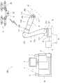
图1是表示本发明的实施方式1所涉及的机器人系统的构成例的示意图。图2是表示图1的机器人系统的应用状态的示意图。FIG. 1 is a schematic diagram illustrating a configuration example of a robot system according to
若参照图1,则机器人系统100具备:机器人10,具有机器人主体1和控制机器人主体1的动作的机器人控制器3;和能够自主飞行的无人飞行器4。无人飞行器4构成为取得机器人主体1的作业的拍摄数据并且发送至机器人控制器3。机器人控制器3构成为接收拍摄数据并利用拍摄数据来控制机器人主体1的动作。Referring to FIG. 1 , a
这里,机器人系统100还具备:机器人操作器2,用于供操作者9(图1中未示出。参照图5)操作机器人主体1;监视器(显示器)5,用于向操作者9提示机器人主体1的作业的影像。无人飞行器4构成为取得机器人主体1的作业的拍摄数据并且发送至机器人控制器3,机器人控制器3构成为接收拍摄数据,基于拍摄数据来在显示器5显示机器人主体1的作业的影像且根据操作者9对机器人操作器2的操作来控制机器人主体1的动作。Here, the
以下,对机器人系统100的结构进行具体说明。机器人系统100具备机器人10、使机器人10移动的移动装置32、无人飞行器4、机器人操作器2、监视器(显示器)5、飞行器操作器6、移动装置操作器7以及操作用通信器8。Hereinafter, the configuration of the
<机器人><Robot>
机器人10具备机器人主体1和机器人控制器3。这里,机器人主体1由多关节的工业用机械臂构成。The
{机器人主体}{robot body}
机器人主体1具备基座15、支承于基座15的臂部13、支承于臂部13的末端的手腕部14、以及作为安装于手腕部14的末端执行器的手部41。这里,手部41由涂装枪构成。The
如图1所示,机器人主体1是具有3以上的多个关节JT1~JT6的多关节机械臂,依次连结多个连杆11a~11f而构成。更详细地说,在第一关节JT1中,基座15与第一连杆11a的基端部连结为能够绕沿铅垂方向延伸的轴旋转。在第二关节JT2中,第一连杆11a的末端部与第二连杆11b的基端部连结为能够绕沿水平方向延伸的轴旋转。在第三关节JT3中,第二连杆11b的末端部与第三连杆11c的基端部连结为能够绕沿水平方向延伸的轴旋转。在第四关节JT4中,第三连杆11c的末端部与第四连杆11d的基端部连结为能够绕沿第四连杆11c的长度方向延伸的轴旋转。在第五关节JT5中,第四连杆11d的末端部与第五连杆11e的基端部连结为能够绕与连杆11d的长度方向正交的轴旋转。在第六关节JT6中,第五连杆11e的末端部与第六连杆11f的基端部连结为能够扭转旋转。而且,在第六连杆11f的末端部设置有机械接口。在该机械接口,以能够装卸的方式安装有作为与机械臂11的作业内容对应的末端执行器的手部41。As shown in FIG. 1 , the robot
由上述的第一关节JT1、第一连杆11a、第二关节JT2、第二连杆11b、第三关节JT3、以及第三连杆11c所构成的连杆与关节的连结体,形成机械臂11的臂部13。另外,由上述的第四关节JT4、第四连杆11d、第五关节JT5、第五连杆11e、第六关节JT6以及第四连杆11f所构成的连杆与关节的连结体,形成机械臂11的手腕部14。A connected body of links and joints composed of the above-mentioned first joint JT1,
在关节JT1~JT6设置有作为使其所连结的两个部件相对旋转的促动器的一个例子的驱动马达(未图示)。驱动马达例如是被从机器人控制器3发送的控制信号经由伺服放大器伺服控制的伺服马达。另外,在关节JT1~JT6设置有用于检测驱动马达的旋转角的旋转角传感器(未图示)、和用于检测驱动马达的电流的电流传感器(未图示)。Joints JT1 to JT6 are provided with drive motors (not shown) as an example of actuators that relatively rotate two connected members. The drive motor is, for example, a servo motor servo-controlled by a control signal sent from the
{控制器}{controller}
控制器3例如具备处理器与存储器。控制器3通过由处理器读出并执行储存于存储器的规定的动作程序来控制机器人主体1的动作。具体而言,控制器3例如由微控制器、MPU、FPGA(Field Programmable Gate Array),PLC(Programmable Logic Controller)、逻辑电路等构成。控制器3使用旋转角传感器的检测信号和电流传感器的检测信号作为反馈信号来生成机器人主体1的臂部13以及手腕部14的控制信号,对臂部13以及手腕部14的动作进行反馈控制。并且,机器人控制器3根据上述的规定的动作程序来控制机器人主体1的手部41的动作。The
<移动装置><Mobile device>
机器人10安装于移动装置32。移动装置32构成为能够在铅垂方向以及水平方向移动机器人主体1。The
参照图2,移动装置32例如具有设置于设置面的基座51。在基座51上立设有支柱52。在支柱52,以能够借助移动机构54(图2中未示出。参照图3)在铅垂方向以及水平方向上移动的方式设置有可动体53。移动机构54例如由公知的2轴移动机构构成。可动体53例如由水平的棒状的框体构成。在可动体53的一方的端部设置机器人主体1。Referring to FIG. 2 , the
<无人飞行器><Unmanned Aerial Vehicle>
参照图1,无人飞行器4例如由无人驾驶飞机构成。无人飞行器4例如包括主体21和设置于主体21的4个旋转翼20。在主体21设置有照相机22。无人飞行器4具有操作模式和自主飞行模式,在不接受来自飞行器操作器6的操作指令的状态下自主飞行,若从飞行器操作器6接受飞行器操作指令,则切换为操作模式,根据飞行器操作指令来飞行。照相机22构成为能够在正交的2个平面内变更姿势,且具有自动对焦功能。照相机22为了拍摄机器人10的作业而使用。Referring to FIG. 1 , the unmanned
<操作器群><Operator Group>
在机器人系统100配置有操作机29。操作机29配置在离开机器人10的应用对象的场所。在操作机29之上配置有机器人操作器2、监视器(显示器)5、飞行器操作器6以及移动装置操作器7。另外,在操作机29设置有操作用通信器8。机器人操作器2由控制杆、主机器人等构成,输出与其操作对应的机器人操作指令。在飞行器操作器6设置有飞行器操作部和照相机操作部。飞行器操作部由控制杆、操纵棒等构成,输出与其操作对应的飞行器操作指令。照相机操作部由按钮、拨盘等适当的操作机构构成,输出与其操作对应的照相机操作指令。移动装置操作器7由控制杆等构成,输出与其操作对应的移动指令。A
[应用环境][Application Environment]
参照图2,在本实施方式1中,机器人10例如应用于船舶31的舣装。换言之,在本实施方式1中,机器人10的应用对象物为船舶31,机器人10(机器人主体1)的作业是舣装,机器人10(机器人主体1)的作业对象为船舶31的被舣装的部位。Referring to FIG. 2 , in
船舶31由于庞大,因而固定的监视照相机容易形成死角。另外,存在大量的机器人10的作业部位。因此,船舶31若应用本实施方式1的机器人系统100,则能够获得特别显著的效果。Since the
在图2的例子中,机器人主体1通过作为具备在末端部的手部41的涂装枪来进行船舶31的船体的侧面31a的涂装。另外,无人飞行器4通过照相机22拍摄机器人主体1的作业。In the example of FIG. 2 , the robot
[控制系统的结构][Structure of the control system]
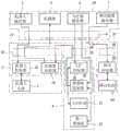
图3是表示图1的机器人系统的控制系统的构成例的框图。参照图3,操作机29具备机器人操作器2、监视器5、飞行器操作器6、移动装置操作器7以及操作用通信器8。操作用通信器8将从机器人操作器2、飞行器操作器6以及移动装置操作器7发送的指令发送至机器人通信器42或者飞行器通信器24。另外,操作用通信器8将从机器人通信器42接收的显示控制信号发送至监视器5。监视器5显示与接收到的显示控制信号对应的图像。FIG. 3 is a block diagram showing a configuration example of a control system of the robot system in FIG. 1 . Referring to FIG. 3 , the
机器人10具备机器人控制器3、机器人主体1以及机器人通信器42。机器人通信器42将从机器人控制器3发送的显示控制信号发送至操作用通信器8,且将从操作用通信器8以及飞行器通信器24接收的机器人操作指令以及拍摄数据发送至机器人控制器3。机器人控制器3包括机器人控制部18和监视器控制部19。机器人控制部18根据经由机器人通信器42接受的来自机器人操作器2的机器人操作指令来控制机器人主体1的动作。监视器控制部19经由机器人通信器42向监视器5发送显示控制信号,使监视器5显示与显示控制信号对应的图像。特别地,监视器控制部19经由机器人通信器42接受来自照相机控制部26的拍摄数据,使与该拍摄数据对应的图像显示于监视器5。The
无人飞行器4具备飞行器控制器23、飞行机构27、照相机22以及飞行器通信器24。飞行机构27是使无人飞行器4向所希望的方向飞行的机构,包括旋转翼20的驱动源以及旋转翼的角度调整机构。飞行器通信器24将从飞行器控制器23发送的拍摄数据发送至机器人通信器42,且将从飞行器操作器6接收的操作指令发送至飞行器控制器23。飞行器控制器23包括飞行控制部25和照相机控制部26。飞行控制部25在自主模式下根据规定的程序来以无人飞行器4进行规定的飞行的方式控制飞行机构27。另外,若经由飞行器通信器24接受来自飞行器操作器6的飞行器操作指令,则飞行控制部25根据该飞行器操作指令来以无人飞行器4进行与该飞行器操作指令对应的飞行的方式控制飞行机构27。若从飞行器操作器6经由飞行器通信器24接受照相机操作指令,则照相机控制部26根据该照相机操作指令来控制照相机22的动作(开关以及姿势)。另外,照相机控制部26将照相机22所拍摄到的拍摄数据发送至飞行器通信器24。The unmanned
移动装置32具备移动控制器55、移动机构54以及移动装置通信器56。移动装置通信器56将从操作用通信器8接收的移动指令发送至移动控制器55。参照图2,移动控制器55根据移动指令来以可动体53移动的方式控制移动机构54。The
这里,操作用通信器8、机器人通信器42、飞行器通信器24以及移动装置通信器56之间的通信、及机器人通信器42与飞行器通信器24之间的通信为无线,但也可以为有线。Here, the communication between the
[动作][action]
接下来,对如以上那样构成的机器人系统100的动作(使用方法)进行说明。换言之,机器人系统100的动作(使用方法)是使用机器人系统100制作物品的方法。这里,如图2所示,举机器人主体1进行船舶31的船体的涂装的情况为例进行说明。Next, the operation (how to use) of the
图4是表示图1的机器人系统100的使用方法的流程图。FIG. 4 is a flowchart illustrating a method of using the
<准备作业><Preparation>
参照图1~图4,首先,操作者9一边目视观察无人飞行器4一边以无人飞行器4飞行至所希望的位置的方式操作飞行器操作器6的飞行器操作部(步骤S1)。Referring to FIGS. 1 to 4 , first, the operator 9 operates the aircraft operating unit of the
于是,飞行器控制器23的飞行控制部25控制飞行机构27来使无人飞行器4根据飞行器操作部的操作飞行。若无人飞行器4位于所希望的位置,则操作者9从飞行器操作部放开手。于是,无人飞行器4移至自主模式,以停在该位置的方式飞行。另一方面,其间,无人飞行器4的照相机所拍摄到的拍摄数据从飞行器控制器23的照相机控制部26发送至机器人控制器3的监视器控制部19,通过监视器控制部19将与该拍摄数据对应的图像显示于监视器5。操作者9一边观察监视器5一边以机器人主体1的作业对象(这里为船舶31的船体的侧面31a的所希望的涂装部位)显示于监视器5的方式操作飞行器操作器6的照相机操作部。于是,飞行器控制器23的照相机控制部26根据该操作来使照相机22的姿势变化,由此,机器人主体1的作业对象(涂装部位)显示于监视器5。Then, the
<正式作业><Official work>
接下来,操作者9一边观察监视器5一边以机器人主体1接近机器人主体1的作业对象的方式操作移动装置操作器7。于是,移动装置32的移动控制器55控制移动机构54来使机器人主体1接近机器人主体1的作业对象。接下来,操作者9操作机器人操作器2来通过机器人主体1的涂装枪对船舶31的船体的侧面31a的所希望的涂装部位开始涂装。另一方面,无人飞行器4的照相机22拍摄该涂装作业,将其拍摄数据发送至照相机控制部26。照相机控制部26将该拍摄数据发送至机器人控制器3的监视器控制部19(步骤S2)。Next, the operator 9 operates the
监视器控制部19(机器人控制器3)将与该拍摄数据对应的影像亦即拍摄到的涂装作业的影像显示于监视器5(步骤S3)。The monitor control unit 19 (robot controller 3 ) displays an image corresponding to the imaging data, that is, an imaged image of the painting work, on the monitor 5 (step S3 ).
操作者9一边观察显示于该监视器5的涂装作业的影像一边操作机器人操作器2来进行涂装。而且,若该涂装部位的涂装结束,则操作者9以机器人主体1移动至下一作业对象(船舶31的船体的侧面31a的下一涂装部位)的方式操作移动装置操作器7。于是,移动装置32的移动控制器55控制移动机构54来使机器人主体1接近机器人主体1的下一作业对象。接下来,操作者9一边观察监视器5的影像一边操作机器人操作器2来通过机器人主体1的涂装枪对下一作业对象(船舶31的船体的侧面31a的下一涂装部位)进行涂装(步骤S4)。The operator 9 performs painting by operating the
此后,重复步骤S2~步骤S4,若预定的涂装作业结束,则结束船舶31的船体的涂装。Thereafter, steps S2 to S4 are repeated, and when the scheduled painting operation ends, the painting of the hull of the
[作用效果][Effect]
如以上说明的那样,根据本实施方式1,无人飞行器4取得机器人主体1的作业的拍摄数据并且发送至机器人控制器3,机器人控制器3基于该拍摄数据将机器人主体1作业的影像示出在显示器(监视器5),操作者9通过机器人操作器2来经由机器人控制器3控制机器人主体1的动作,因而使无人飞行器4移动至适于拍摄机器人应用对象物(船舶31)的作业对象(船体的侧面31a的涂装部位)的位置,由此操作者9能够一边观察显示于显示器(监视器5)的机器人主体1的作业的影像一边操作机器人主体1。因此,能够适当地应对成为固定的监视照相机的死角的作业对象(船体的侧面31a的涂装部位)多的机器人应用对象物(船舶)。As described above, according to the first embodiment, the unmanned
另外,机器人系统100还具备安装了机器人主体1的移动装置32和用于供操作者9操作移动装置32的移动装置操作器7,移动装置32构成为能够在铅垂方向以及水平方向上移动机器人主体1,因而操作者9能够通过操作移动装置操作器7来使机器人主体1在铅垂方向以及水平方向上移动。其结果是,能够适当地进行机器人主体1的作业。In addition, the
(实施方式1的变形例)(Modification of Embodiment 1)
图5是表示本发明的实施方式1的变形例所涉及的机器人系统的应用状态的示意图。图6是表示图5所示的机器人系统的控制系统的构成例的框图。5 is a schematic diagram showing an application state of a robot system according to a modified example of
如图5所示,实施方式1的变形例的机器人系统200在移动装置33构成为能够行驶这一点上与实施方式1(基本结构)的机器人系统100不同,其他结构与实施方式1的机器人系统100相同。以下,对该不同点进行说明。As shown in FIG. 5 , a
参照图5,移动装置33例如由公知的吊车构成。该移动装置33具备车辆34和设置于车辆34的货台部分的曲折式的吊杆(起重臂)35。而且,在吊杆35的末端部设置有由多关节型的工业用机械臂构成机器人主体1。船舶31比实施方式1的船舶31大。因此,通过机器人主体1涂装船舶31的船体的侧面31a时,需要使机器人主体1在宽大的范围移动。其中,附图标记36表示喷雾状的涂料,附图标记37表示船舶31的船体的侧面31a的不同喷涂的分界线。Referring to FIG. 5 , the moving
在本变形例中,移动装置操作器7构成为能够供操作者9使移动装置33以所希望的速度向所希望的方向行驶,且使曲折式的吊杆35向所希望的方向旋转且伸缩为所希望的程度。In this modified example, the moving
在本变形例中,操作者9能够通过适当地操作移动装置33使机器人主体1移动至所希望的位置。具体而言,操作者9通过操作飞行器操作器6来以机器人主体1的应用对象亦即船舶31与移动装置33同时显示于监视器5的方式对无人飞行器4以及照相机22进行远程控制。另一方面,操作者9一边观察显示于监视器5的船舶31和移动装置33一边操作移动装置操作器7来以机器人主体1接近船舶31的船体的侧面31a的所希望的涂装部位的方式使移动装置33的车辆34行驶并且使吊杆35伸缩。这样,在本变形例中,操作者9能够使机器人主体1在宽大的范围移动。其结果是,即便船舶31庞大,也能够适当地涂装船舶31的船体的侧面31a。In this modified example, the operator 9 can move the robot
(实施方式2)(Embodiment 2)
本发明的实施方式2的机器人系统300主要是机器人主体1以及无人飞行器4分别根据规定的程序来动作这一点与实施方式1的机器人系统100不同。以下,对与实施方式1的机器人系统100的不同点进行说明。The
[结构][structure]
图7是表示本发明的实施方式2所涉及的机器人系统的硬件的构成例的示意图。7 is a schematic diagram illustrating an example of a hardware configuration of a robot system according to
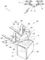
参照图7,机器人系统300具备台车70。这里,台车70由在基部具备车轮70a的箱体构成。台车70能够通过车轮70a移动,能够在所希望的场所停止。车轮70a被未图示的驱动机构驱动。该驱动机构例如具备伺服马达作为驱动源。车轮70a与该驱动机构构成移动机构54(参照图8)。Referring to FIG. 7 , the
在台车70的上表面设置有作为机器人主体1的机械臂。机械臂进行后述的规定的作业。因此,机械臂只要具有臂且能够进行规定的作业即可。例如,能够例示水平多关节机器人、垂直多关节机器人、平行连杆机器人、正交机器人等。这里,机械臂为双臂水平多关节机器人。A robot arm as the robot
机械臂设置于台车70的上表面,具有沿上下方向延伸的圆柱状的基部71和支承于基部71的右臂以及左臂。右臂包括:右第一连杆72A,基端部以能够绕基部71的中心轴亦即第一转动轴线转动的方式支承于基部71;右第二连杆73A,基端部以能够绕与第一转动轴线平行的第二转动轴线转动的方式支承于右第一连杆72A的末端部;右肘杆部74A,以能够绕垂直于第二转动轴线的第三转动轴线扭转旋转且能够升降的方式支承于右第二连杆73A的末端部;以及右手部76A,安装于右肘杆部74A的下端。右第一连杆72A、右第二连杆73A以及右肘杆部74A构成右臂部75A。The robot arm is provided on the upper surface of the
左臂包括:左第一连杆72B,基端部以能够绕基部71的中心轴亦即第一转动轴线转动的方式支承于基部71;左第二连杆73B,基端部以能够绕与第一转动轴线平行的第四转动轴线转动的方式支承于左第一连杆72B的末端部;左肘杆部74B,以能够绕垂直于第四转动轴线的第五转动轴线扭转旋转且能够升降的方式支承于左第二连杆73B的末端部;以及左手部76B,安装于左肘杆部74B的下端。左第一连杆72B、左第二连杆73B以及左肘杆部74B构成左臂部75B。这里,右手部76A包括固定于右肘杆部74A的下端部的基体77A、和从基体77A起延伸为与右肘杆部74A的第三转动轴线平行的细长的板状的爪部件78A。左手部76B包括固定于左肘杆部74B的下端部的基体77B、和从基体77B起延伸为与左肘杆部74B的第五转动轴线平行的细长的板状的爪部件78B。左右的臂能够独立动作或相互配合动作。这里,机器人10将一对爪部件78A、78B对齐成叉状来输送后述的栽培床83(参照图10)。The left arm includes: a left
在台车70的内部收纳有机器人控制器3以及机器人通信器42。机器人控制器3通过由处理器读出并执行储存于存储器的规定的控制程序来完全自动地控制机器人主体1、台车70以及无人飞行器4的动作。机器人主体1(机械臂)与机器人控制器3构成机器人10。The
参照图8,机器人控制器3根据规定的控制程序来控制台车70的移动机构54以及机器人主体1的动作。Referring to FIG. 8 , the
另外,机器人控制器3根据规定的控制程序来将飞行控制信号发送至无人飞行器4的飞行器控制器23的飞行控制部25。无人飞行器4具有自主模式和与实施方式1的操作模式相当的外部控制模式。飞行控制部25在自主模式下根据规定的程序来以无人飞行器4进行规定的飞行的方式控制飞行机构27。另外,若经由飞行器通信器24接受来自机器人控制器3的飞行控制信号,则切换为外部控制模式,飞行控制部25根据该飞行控制信号来以无人飞行器4进行与该飞行控制信号对应的飞行的方式控制飞行机构27。In addition, the
无人飞行器4具备第一照相机22和第二照相机28。第一照相机22与实施方式1的照相机22相同。第二照相机28构成为能够在正交的2个平面内变更姿势,且能够在无人飞行器4的水平面内在360度的范围内改变方向(光轴方向)。第二照相机28具有自动对焦功能。The unmanned
机器人控制器3根据规定的控制程序将照相机控制信号发送至无人飞行器4的飞行器控制器23的照相机控制部26。照相机控制部26根据该照相机控制信号来分别控制第一照相机22的姿势及第二照相机28的姿势以及方向。第一照相机22的动作以及与第一照相机22相关的照相机控制部26的动作与实施方式1同样。但是,这里,照相机控制部26将第一照相机的拍摄数据发送至机器人控制器3。The
第二照相机28例如由三维照相机构成,将其拍摄数据发送至照相机控制部26。照相机控制部26通过对该拍摄数据进行图像处理来检测第二照相机28与被拍摄体之间的距离。在本实施方式2中,例如,被拍摄体具有规定形状,或对被拍摄体标注规定的识别标志,照相机控制部26存储有该规定的形状或者该规定的识别标志,通过对拍摄数据是否存在与该规定的形状或者该规定的识别标志一致的区域进行判定来从拍摄数据检测(提取)被拍摄体。The
无人飞行器4例如具备GPS,照相机控制部26从GPS的位置信息检测无人飞行器4(准确地说为无人飞行器4的基准位置)的空间位置。而且,基于无人飞行器4的空间位置、第二照相机28的在无人飞行器4中的位置、第二照相机28的姿势以及方向、第二照相机28与被拍摄体之间的距离,来检测被拍摄体的空间位置。然后,将该检测出的被拍摄体的空间位置发送至机器人控制器3。这里,作为被拍摄体,至少设定有机器人主体1、作为作业对象的栽培床83(参照图9)、作为机器人主体1移动的情况下的障碍物的集合棚82。The unmanned
[应用环境][Application Environment]
图9是表示图7的机器人系统300的应用状态的示意图。图10是示意性表示图9的单位棚的结构的主视图。FIG. 9 is a schematic diagram showing an application state of the
参照图9,本实施方式2的机器人系统300的机器人主体1的应用对象是无人的蔬菜培育工厂80。蔬菜培育工厂80例如是完全封闭型。蔬菜培育工厂80具备顶棚高且具有比较宽的内部空间的工厂81。在工厂81的内部,以空开能够供机器人10一边进行规定的作业一边行驶的间隔的方式配置有多个集合棚82。各集合棚82是将规定数量的单位棚82a相互使侧面接触配置而成。Referring to FIG. 9 , the
参照图10,单位棚82a例如分隔成3层,上层以及中层使用在蔬菜的培育中。蔬菜的培育使用移动式的栽培床83。栽培床83构成为在发泡苯乙烯等的主体83a设置有一对脚部83b。在主体83a上培育蔬菜。另外,在一对脚部83b之间的空间84插入机器人10的一对爪部件78A、78B。在上层以及中层的顶棚分别设置有用于向栽培床83上的蔬菜照射规定的光的照明器具85,且设置有用于向栽培床83上的蔬菜供给营养液且从栽培床83排出使用完的营养液的装置(未图示)。Referring to Fig. 10, the unit shed 82a is divided into three layers, for example, and the upper layer and the middle layer are used for growing vegetables. Vegetables are cultivated using a
对多个集合棚分配蔬菜的多个繁殖步骤,各个集合棚维持成与各个繁殖步骤对应的繁殖环境。各栽培床83根据该栽培床83上的蔬菜的繁殖程度来在多个集合棚依次移动。A plurality of multiplication steps of vegetables are distributed to a plurality of collection sheds, and each collection shed maintains a multiplication environment corresponding to each multiplication step. Each
在机器人控制器3存储有图9所示的工厂81的布局即工厂81的内部空间的尺寸、集合棚82的配置以及尺寸、各集合棚82内的单位棚82a的配置以及尺寸、各单位棚82a中的各层的配置以及尺寸等。Stored in the
[动作][action]
<基本动作><Basic Action>
在本实施方式2中,仅无人飞行器4具备GPS,机器人10不具备GPS。其理由如下所述。这是因为:在本实施方式2中,GPS的位置误差相比于工厂81的大小而言相对大。如若无人飞行器4与机器人10这两者基于GPS的位置信息来确定各自的位置以及集合棚82等,则产生GPS的误差的相加,而存在在机器人10的作业中产生妨碍的可能性。当然,在GPS的位置误差相比于工厂81的大小而言相对小的情况下,也可以是无人飞行器4与机器人10这两者具备GPS。In
在本实施方式2中,机器人控制器3一边使无人飞行器4在工厂81内盘旋一边经由照相机控制部26以规定的周期以及适当的姿势使第二照相机22的方向(光轴方向)在无人飞行器4的水平面内改变360度。换言之,使第二照相机22在无人飞行器4的水平面内旋转。而且,照相机控制部26通过如上述那样进行被拍摄体的拍摄以及与被拍摄体的距离检测,来检测机器人主体1的空间位置与障碍物亦即各集合棚(准确地说为其基准位置)82的空间位置,并将它们发送至机器人控制器3。In the second embodiment, the
<具体的动作><Specific action>
图11是表示图7的机器人系统300的动作(使用方法)的流程图。机器人系统300的动作通过机器人10的机器人控制器3的控制来完成。FIG. 11 is a flowchart showing the operation (method of use) of the
参照图10以及图11,机器人控制器3使无人飞行器4在工厂81盘旋(步骤S11)。其间,如上述那样,使第二照相机旋转,从照相机控制部26取得机器人主体1的空间位置与障碍物亦即各集合棚(准确地说为其基准位置)82的空间位置。10 and 11 , the
然后,机器人控制器3对是否存在符合条件的项目进行判定(步骤S12)。“项目”是指需要机器人10进行某些作业的现象。这里,例如是根据栽培床83上的蔬菜的繁殖程度来变更(移动)载置该栽培床83的集合棚82。“条件”是指机器人10进行某些作业的条件。这里,栽培床83上的蔬菜的繁殖程度意味着变更载置该栽培床83的集合棚82的条件。具体而言,机器人控制器3通过经由无人飞行器4的照相机控制部26控制第一照相机22来使第一照相机22拍摄各集合棚82的各栽培床83上的蔬菜,基于该拍摄数据来监视各栽培床83上的蔬菜的繁殖程度。具体而言,机器人控制器3例如对拍摄数据进行图像处理来检测蔬菜的高度。另一方面,机器人控制器3存储将多个繁殖步骤与各步骤中的蔬菜的上限高度建立对应的对比表格,机器人控制器3将检测到的蔬菜的高度与该对比表格进行比较,而对各栽培床83上的蔬菜的高度是否超过与分配给载置有各栽培床83的单位棚82a所属的集合棚82的繁殖步骤对应的蔬菜的上限高度进行判定。Then, the
在“不超过”的情况下,判定为“不存在符合条件的项目”(在步骤S12中为否),然后,对是否结束培育工作进行判定(步骤S16),在不结束培育工作的情况下(在步骤S16中为否),返回至步骤S11。此外,在结束培育工作的情况下(在步骤S16中为是),结束该机器人系统300的动作。在该情况下,无人飞行器4着陆于规定位置。In the case of "not exceeding", it is judged as "there is no eligible item" (no in step S12), and then it is judged whether to end the cultivation work (step S16), and if the cultivation work is not ended (No in step S16), return to step S11. Also, when the cultivation work is terminated (YES in step S16), the operation of the
另一方面,在“超过”的情况下,判定为“存在符合条件的项目”(在步骤S12中为是),进入步骤S13。以下,将与该“符合条件的项目”对应的栽培床83称为“符合栽培床”。On the other hand, in the case of "exceeding", it is determined that "there is an item conforming to the condition" (YES in step S12), and the process proceeds to step S13. Hereinafter, the
在步骤S13中,机器人控制器3确定符合场所。这里,该“符合场所”是载置有符合栽培床83的单位棚82a的层。具体而言,机器人控制器3经由无人飞行器4的照相机控制部26来以第二照相机28取与第一照相机22相同的姿势以及方向的方式控制第二照相机22。于是,照相机控制部26如上述那样动作来检测符合栽培床的空间位置,将其发送至机器人控制器3。在该情况下,照相机控制部26存储栽培床83的形状,基于该存储的栽培床83的形状来通过图像处理提取符合栽培床83作为被拍摄体(作业对象),检测其距离。然后,使用该距离来如上述那样检测符合栽培床83的空间位置,将其发送至机器人控制器3。机器人控制器3基于该符合栽培床83的空间位置与自身所存储的工厂81的布局来确定载置有符合栽培床83的单位棚82a的层并且确定该符合栽培床83的空间位置。In step S13, the
另外,机器人控制器3确定分配了与符合栽培床83上的蔬菜的高度对应的繁殖步骤的集合棚82且在确定出的集合棚82确定具有空着的层的单位棚82a。以下,将该单位棚82a的空着的层称为移动目标层。接下来,机器人控制器3基于从无人飞行器4的照相机控制部26发送的机器人主体1的空间位置来确定机器人10(台车70)的当前位置。然后,机器人控制器3基于从无人飞行器4的照相机控制部26发送的各集合棚(其基准位置)82的空间位置与工厂81的布局来以规避集合棚82的方式设定机器人10(台车70)的移动路径。In addition, the
接下来,机器人控制器3使机器人10移动至符合场所(步骤S14)。具体而言,机器人控制器3控制台车70的移动机构54通过上述移动路径来使机器人10移动至符合栽培床83的正面。Next, the
接下来,机器人控制器3使机器人10进行所需的作业(步骤S15)。具体而言,机器人控制器3使机器人主体1将一对爪部件78A、76B插入至符合栽培床83的一对脚部83b之间的空间84,接下来,使一对爪部件78A、76B稍微上升来抬起符合栽培床83。接下来,机器人控制器3使机器人主体1从单位棚82a抽出符合栽培床83。接下来,机器人控制器3基于从无人飞行器4的照相机控制部26发送的各集合棚(该基准位置)82的空间位置与工厂81的布局来以规避集合棚82的方式设定机器人10(台车70)的移动路径。Next, the
接下来,机器人控制器3使机器人10通过上述移动路径移动至移动目标层的正面。Next, the
接下来,机器人控制器3使机器人主体1将符合栽培床83移动至移动目标层的上部,然后,使一对爪部件78A、76B稍微下降来将符合栽培床83载置于移动目标层之上,然后,使一对爪部件78A、76B从符合栽培床83的一对脚部83b之间的空间84拔出。由此,结束机器人10所需的作业。Next, the
接下来,机器人控制器3对是否结束培育工作进行判定(步骤S16),在不结束培育工作的情况下(在步骤S16中为否),返回至步骤S11。在结束培育工作的情况下(在步骤S16中为是),结束该机器人系统300的动作。Next, the
<作用效果><Effects>
根据本实施方式2,能够使机器人主体1自动地动作。另外,机器人控制器3使用无人飞行器4来确定机器人主体1的作业对象(符合栽培床83),因而能够使用无人飞行器4来监视宽广的范围。因此,能够容易地确定机器人主体1的作业对象。According to the second embodiment, the robot
另外,机器人主体1构成为能够行驶,无人飞行器4构成为取得机器人主体1的作业对象(符合栽培床83)的位置信息并且发送至机器人控制器3,机器人控制器3构成为若接收作业对象的位置信息,则基于机器人主体1的位置与作业对象的位置信息使机器人主体1行驶至作业对象位置,因而能够使机器人主体1自动地行驶至作业对象位置。In addition, the robot
另外,无人飞行器4构成为还取得存在于从机器人主体1至作业对象的路径的障碍物(集合棚82)的位置信息并且发送至机器人控制器3,机器人控制器3构成为基于接收到的障碍物的位置信息来使机器人主体1规避障碍物行驶至作业对象位置,因而能够自动地使机器人主体1规避存在于从机器人主体1至作业对象的路径的障碍物行驶至作业对象位置。In addition, the unmanned
(其他实施方式)(Other implementations)
在上述实施方式1以及其变形例中,机器人主体1并不限定于多关节的机械臂。机器人主体1可以是平行连杆型机器人、正交型机器人、其他类型的机器人。In
在上述实施方式1及其变形例中,机器人主体1的作业可以不是涂装,而是例如船舶31的船体的组装。在该情况下,移动装置32、33使用适于船舶31的船体的组装的吊车。In
在上述实施方式1及其变形例中,机器人主体1的应用对象物可以是车辆、航空器、桥梁或者建筑物。In the above first embodiment and its modifications, the application object of the robot
根据上述说明,对于本领域技术人员而言,本发明的许多改进、其他实施方式是显而易见的。因此,上述说明应该仅解释为例示,是以将执行本发明的最佳的形态示教给本领域技术人员的目的提供的。在不脱离本发明的精神的范围内能够实际变更其构造以及/或者功能的详细。Based on the above description, many improvements and other implementations of the present invention will be obvious to those skilled in the art. Therefore, the above description should be interpreted as an illustration only, and is provided for the purpose of teaching the best mode for carrying out the present invention to those skilled in the art. The details of the structure and/or functions can be actually changed without departing from the spirit of the present invention.
工业上的利用可能性Industrial Utilization Possibility
本发明的机器人系统及使用其制作物品的方法,作为能够应对成为监视照相机的死角的作业对象多的机器人应用对象物以及需要使机器人移动至各个作业对象的附近的机器人应用对象物中的至少一方的机器人系统及使用其制作物品的方法等有用。The robot system of the present invention and the method of manufacturing an article using the same are used as at least one of a robot application object that can cope with many work objects that become a blind spot of a monitoring camera and a robot application object that needs to move the robot to the vicinity of each work object. Robotic systems and methods of making objects using the same are useful.
附图标记说明:Explanation of reference signs:
1…机器人主体;2…机器人操作器;3…机器人控制器;4…无人飞行器;5…监视器(显示器);6…飞行器操作器;7…移动装置操作器;8…操作用通信器;9…操作者;10…机器人;11…机械臂;18…机器人控制部;19…监视器控制部;20…旋转翼;21…主体;22…照相机(第一照相机);23…飞行器控制器;24…飞行器通信器;25…飞行控制部;26…照相机控制部;27…飞行机构;28…第二照相机;29…操作机;31…船舶;31a…侧面;32…移动装置;33…移动装置;41…手部;42…机器人通信器;54…移动机构;55…移动控制器;56…移动装置通信器;70…台车;80…蔬菜培育工厂;81…工厂;82…集合棚;82a…单位棚;83…栽培床;100、200、300…机器人系统。1...robot main body; 2...robot manipulator; 3...robot controller; 4...unmanned aerial vehicle; 5...monitor (display); 6...aircraft manipulator; 7...mobile device manipulator; 8...communicator for operation 9...operator; 10...robot; 11...mechanical arm; 18...robot control section; 19...monitor control section; 20...rotor wing; 21...main body; 22...camera (first camera); 23...
Claims (15)
Translated fromChineseApplications Claiming Priority (3)
| Application Number | Priority Date | Filing Date | Title |
|---|---|---|---|
| JP2017-224267 | 2017-11-22 | ||
| JP2017224267AJP6944354B2 (en) | 2017-11-22 | 2017-11-22 | Robot system and how to make things using it |
| PCT/JP2018/039944WO2019102789A1 (en) | 2017-11-22 | 2018-10-26 | Robot system and method for creating articles using same |
Publications (2)
| Publication Number | Publication Date |
|---|---|
| CN111432991A CN111432991A (en) | 2020-07-17 |
| CN111432991Btrue CN111432991B (en) | 2023-07-07 |
Family
ID=66631511
Family Applications (1)
| Application Number | Title | Priority Date | Filing Date |
|---|---|---|---|
| CN201880075405.8AActiveCN111432991B (en) | 2017-11-22 | 2018-10-26 | Robot system and method for manufacturing article using the same |
Country Status (6)
| Country | Link |
|---|---|
| US (1) | US11613022B2 (en) |
| EP (1) | EP3715066A4 (en) |
| JP (1) | JP6944354B2 (en) |
| KR (1) | KR102375802B1 (en) |
| CN (1) | CN111432991B (en) |
| WO (1) | WO2019102789A1 (en) |
Families Citing this family (6)
| Publication number | Priority date | Publication date | Assignee | Title |
|---|---|---|---|---|
| CN113056351B (en)* | 2018-11-01 | 2024-07-23 | 佳能株式会社 | External input device, robot system, control method thereof, and recording medium |
| JP7272825B2 (en)* | 2019-03-06 | 2023-05-12 | ファナック株式会社 | robot system |
| CN115697843B (en)* | 2020-06-19 | 2025-08-08 | 川崎重工业株式会社 | Shooting system and robotic system |
| JP7491782B2 (en)* | 2020-09-04 | 2024-05-28 | 川崎重工業株式会社 | Air transport system and air transport method |
| JP7563212B2 (en)* | 2021-02-05 | 2024-10-08 | トヨタ自動車株式会社 | TRANSPORT SYSTEM AND TRANSPORT METHOD |
| CN116088499A (en)* | 2022-12-12 | 2023-05-09 | 广东电网有限责任公司广州供电局 | A UAV auxiliary system for a live working robot system |
Family Cites Families (21)
| Publication number | Priority date | Publication date | Assignee | Title |
|---|---|---|---|---|
| JPH0615594A (en)* | 1992-07-02 | 1994-01-25 | Toshiba Corp | Remote control robot monitoring device |
| JPH11291991A (en)* | 1998-04-03 | 1999-10-26 | Shinshakai System Kenkyusho:Kk | Mobile remote control system |
| JP3631431B2 (en)* | 2000-12-05 | 2005-03-23 | 独立行政法人科学技術振興機構 | Detection device and detection method |
| KR101149515B1 (en)* | 2010-02-12 | 2012-05-25 | 삼성중공업 주식회사 | Welding apparatus and method |
| JP5246672B2 (en)* | 2011-02-17 | 2013-07-24 | 独立行政法人科学技術振興機構 | Robot system |
| EP2511656A1 (en)* | 2011-04-14 | 2012-10-17 | Hexagon Technology Center GmbH | Measuring system for determining the 3D coordinates of an object surface |
| US9214021B2 (en) | 2012-10-09 | 2015-12-15 | The Boeing Company | Distributed position identification |
| US10165722B2 (en) | 2014-12-05 | 2019-01-01 | Deere & Company | Scouting systems |
| KR20170116141A (en)* | 2015-02-13 | 2017-10-18 | 에스코 코포레이션 | Monitoring ground bonding products for earthworks |
| US9855658B2 (en)* | 2015-03-19 | 2018-01-02 | Rahul Babu | Drone assisted adaptive robot control |
| CN204868886U (en)* | 2015-07-10 | 2015-12-16 | 桂林电子科技大学 | Multifunctional machine ware people who can fly in calamity scene |
| JP6598154B2 (en)* | 2015-11-05 | 2019-10-30 | 株式会社Ihiエアロスペース | Explosive detection system |
| CN205486332U (en)* | 2016-01-20 | 2016-08-17 | 珠海市钰海电力有限公司 | Nobody system of patrolling and examining of intelligence |
| JP6938389B2 (en)* | 2016-01-29 | 2021-09-22 | 住友建機株式会社 | Excavator and autonomous aircraft flying around the excavator |
| CN106200667A (en)* | 2016-09-05 | 2016-12-07 | 南京理工大学 | Petrochemical iy produced site intelligent cruising inspection system |
| CN106334283A (en)* | 2016-10-10 | 2017-01-18 | 南京工程学院 | Fire-fighting and rescue robot system and control method |
| CN106965179A (en)* | 2017-04-10 | 2017-07-21 | 浙江谱麦科技有限公司 | The vision positioning system and method for a kind of industrial robot |
| DE102017116659A1 (en) | 2017-07-24 | 2019-01-24 | Vorwerk & Co. Interholding Gmbh | Externally movable working device |
| CN107329487A (en)* | 2017-08-31 | 2017-11-07 | 西南交通大学 | A kind of unmanned plane and robot link job platform in the air |
| US10890921B2 (en)* | 2018-05-31 | 2021-01-12 | Carla R. Gillett | Robot and drone array |
| US20230008259A1 (en)* | 2021-07-09 | 2023-01-12 | Qualcomm Incorporated | Techniques for wideband operation of sidelink communications over unlicensed band |
- 2017
- 2017-11-22JPJP2017224267Apatent/JP6944354B2/enactiveActive
- 2018
- 2018-10-26WOPCT/JP2018/039944patent/WO2019102789A1/ennot_activeCeased
- 2018-10-26KRKR1020207012924Apatent/KR102375802B1/enactiveActive
- 2018-10-26CNCN201880075405.8Apatent/CN111432991B/enactiveActive
- 2018-10-26EPEP18880642.6Apatent/EP3715066A4/enactivePending
- 2018-10-26USUS16/766,362patent/US11613022B2/enactiveActive
Also Published As
| Publication number | Publication date |
|---|---|
| KR20200066673A (en) | 2020-06-10 |
| KR102375802B1 (en) | 2022-03-17 |
| US20200376677A1 (en) | 2020-12-03 |
| WO2019102789A1 (en) | 2019-05-31 |
| US11613022B2 (en) | 2023-03-28 |
| EP3715066A1 (en) | 2020-09-30 |
| JP2019093471A (en) | 2019-06-20 |
| EP3715066A4 (en) | 2021-09-08 |
| CN111432991A (en) | 2020-07-17 |
| JP6944354B2 (en) | 2021-10-06 |
Similar Documents
| Publication | Publication Date | Title |
|---|---|---|
| CN111432991B (en) | Robot system and method for manufacturing article using the same | |
| CN111819510B (en) | flying robot | |
| Paul et al. | A multirotor platform employing a three-axis vertical articulated robotic arm for aerial manipulation tasks | |
| EP3620393B1 (en) | Mobile fixture apparatuses and methods | |
| CN106695748A (en) | Hot-line robot with double mechanical arms | |
| Laiacker et al. | High accuracy visual servoing for aerial manipulation using a 7 degrees of freedom industrial manipulator | |
| Paul et al. | Landing of a multirotor aerial vehicle on an uneven surface using multiple on-board manipulators | |
| JP7023492B2 (en) | Follow-up image presentation system for moving objects | |
| US10782696B2 (en) | Mobile fixture apparatuses and methods | |
| JP7272825B2 (en) | robot system | |
| CN111015681A (en) | Communication machine room inspection robot system | |
| CN106737862B (en) | A data communication system for live working robot | |
| US11072439B2 (en) | Mobile fixture apparatuses and methods | |
| CN206445826U (en) | A kind of hot line robot data communication system | |
| US12228948B2 (en) | Imaging system and robot system | |
| CN108170160A (en) | It is a kind of to utilize monocular vision and the autonomous grasping means of airborne sensor rotor wing unmanned aerial vehicle | |
| CN114290348A (en) | End effector for tunnel inspection robot, inspection robot and control method thereof | |
| Dobrokvashina et al. | Improved graphical user interface for crawler robot servosila engineer | |
| CN113179862A (en) | Control system and control method of humanoid mushroom picking double-arm robot | |
| CN117484520A (en) | Automatic calibration robot, control method and storage medium | |
| Narváez et al. | Vision based autonomous docking of VTOL UAV using a mobile robot manipulator | |
| Ladig et al. | High precision marker based localization and movement on the ceiling employing an aerial robot with top mounted omni wheel drive system | |
| WO2019040008A1 (en) | Technological equipment for work in height | |
| Anderson et al. | Coordinated control and range imaging for mobile manipulation | |
| CN215954360U (en) | Security protection system of patrolling and examining, four-footed robot and unmanned aerial vehicle |
Legal Events
| Date | Code | Title | Description |
|---|---|---|---|
| PB01 | Publication | ||
| PB01 | Publication | ||
| SE01 | Entry into force of request for substantive examination | ||
| SE01 | Entry into force of request for substantive examination | ||
| GR01 | Patent grant | ||
| GR01 | Patent grant |