CN111432721A - Physiological monitoring device and system for providing monitoring of physiological data of a patient - Google Patents
Physiological monitoring device and system for providing monitoring of physiological data of a patientDownload PDFInfo
- Publication number
- CN111432721A CN111432721ACN201880076622.9ACN201880076622ACN111432721ACN 111432721 ACN111432721 ACN 111432721ACN 201880076622 ACN201880076622 ACN 201880076622ACN 111432721 ACN111432721 ACN 111432721A
- Authority
- CN
- China
- Prior art keywords
- ecg
- module
- physiological
- electrodes
- data
- Prior art date
- Legal status (The legal status is an assumption and is not a legal conclusion. Google has not performed a legal analysis and makes no representation as to the accuracy of the status listed.)
- Pending
Links
- 238000012544monitoring processMethods0.000titleclaimsabstractdescription80
- 238000012806monitoring deviceMethods0.000titledescription12
- 238000004891communicationMethods0.000claimsabstractdescription98
- 230000002159abnormal effectEffects0.000claimsabstractdescription47
- 238000004458analytical methodMethods0.000claimsabstractdescription20
- 230000015654memoryEffects0.000claimsdescription58
- 239000000463materialSubstances0.000claimsdescription24
- 230000035790physiological processes and functionsEffects0.000claimsdescription11
- 230000005540biological transmissionEffects0.000claimsdescription10
- 230000001413cellular effectEffects0.000claimsdescription8
- 238000013480data collectionMethods0.000claims2
- 238000004573interface analysisMethods0.000claims2
- 230000001105regulatory effectEffects0.000claims1
- 239000000853adhesiveSubstances0.000description14
- 230000000747cardiac effectEffects0.000description13
- 238000000034methodMethods0.000description11
- 229920000642polymerPolymers0.000description11
- 230000001070adhesive effectEffects0.000description10
- 230000003321amplificationEffects0.000description10
- 238000001914filtrationMethods0.000description10
- 238000003199nucleic acid amplification methodMethods0.000description10
- 238000012545processingMethods0.000description9
- 239000004744fabricSubstances0.000description8
- 239000006260foamSubstances0.000description8
- 238000005259measurementMethods0.000description8
- 239000011148porous materialSubstances0.000description8
- 229910052710siliconInorganic materials0.000description8
- 239000010703siliconSubstances0.000description8
- 238000010586diagramMethods0.000description7
- 229920005570flexible polymerPolymers0.000description6
- 239000007789gasSubstances0.000description6
- XLYOFNOQVPJJNP-UHFFFAOYSA-NwaterSubstancesOXLYOFNOQVPJJNP-UHFFFAOYSA-N0.000description6
- 238000006243chemical reactionMethods0.000description5
- 230000000694effectsEffects0.000description5
- 210000003414extremityAnatomy0.000description5
- 230000007246mechanismEffects0.000description5
- 230000006793arrhythmiaEffects0.000description4
- 206010003119arrhythmiaDiseases0.000description4
- 230000006835compressionEffects0.000description4
- 238000007906compressionMethods0.000description4
- 238000004590computer programMethods0.000description4
- 230000006870functionEffects0.000description4
- 230000006872improvementEffects0.000description4
- 208000028867ischemiaDiseases0.000description4
- 208000010125myocardial infarctionDiseases0.000description4
- 230000003287optical effectEffects0.000description3
- 230000004044responseEffects0.000description3
- CURLTUGMZLYLDI-UHFFFAOYSA-NCarbon dioxideChemical compoundO=C=OCURLTUGMZLYLDI-UHFFFAOYSA-N0.000description2
- HBBGRARXTFLTSG-UHFFFAOYSA-NLithium ionChemical compound[Li+]HBBGRARXTFLTSG-UHFFFAOYSA-N0.000description2
- 210000003484anatomyAnatomy0.000description2
- 238000002554cardiac rehabilitationMethods0.000description2
- 238000013461designMethods0.000description2
- 238000005516engineering processMethods0.000description2
- 230000002045lasting effectEffects0.000description2
- 210000005240left ventricleAnatomy0.000description2
- 239000004973liquid crystal related substanceSubstances0.000description2
- 229910001416lithium ionInorganic materials0.000description2
- 230000035479physiological effects, processes and functionsEffects0.000description2
- 239000002861polymer materialSubstances0.000description2
- 239000010409thin filmSubstances0.000description2
- 238000012546transferMethods0.000description2
- 208000034657ConvalescenceDiseases0.000description1
- 230000001154acute effectEffects0.000description1
- 238000003491arrayMethods0.000description1
- QVGXLLKOCUKJST-UHFFFAOYSA-Natomic oxygenChemical compound[O]QVGXLLKOCUKJST-UHFFFAOYSA-N0.000description1
- 230000008901benefitEffects0.000description1
- 230000036772blood pressureEffects0.000description1
- 210000001217buttockAnatomy0.000description1
- 229910002092carbon dioxideInorganic materials0.000description1
- 239000001569carbon dioxideSubstances0.000description1
- 238000004140cleaningMethods0.000description1
- 230000003750conditioning effectEffects0.000description1
- 239000004020conductorSubstances0.000description1
- 238000007405data analysisMethods0.000description1
- 238000001514detection methodMethods0.000description1
- 238000004070electrodepositionMethods0.000description1
- 239000000383hazardous chemicalSubstances0.000description1
- 238000003384imaging methodMethods0.000description1
- 230000036039immunityEffects0.000description1
- 208000015181infectious diseaseDiseases0.000description1
- 238000009413insulationMethods0.000description1
- 230000010354integrationEffects0.000description1
- 238000012986modificationMethods0.000description1
- 230000004048modificationEffects0.000description1
- 229910052760oxygenInorganic materials0.000description1
- 239000001301oxygenSubstances0.000description1
- 230000002093peripheral effectEffects0.000description1
- 229920001296polysiloxanePolymers0.000description1
- 238000011084recoveryMethods0.000description1
- 230000000717retained effectEffects0.000description1
- 210000005241right ventricleAnatomy0.000description1
- 239000013598vectorSubstances0.000description1
Images


Classifications
- A—HUMAN NECESSITIES
- A61—MEDICAL OR VETERINARY SCIENCE; HYGIENE
- A61B—DIAGNOSIS; SURGERY; IDENTIFICATION
- A61B5/00—Measuring for diagnostic purposes; Identification of persons
- A61B5/0002—Remote monitoring of patients using telemetry, e.g. transmission of vital signals via a communication network
- A61B5/0004—Remote monitoring of patients using telemetry, e.g. transmission of vital signals via a communication network characterised by the type of physiological signal transmitted
- A61B5/0006—ECG or EEG signals
- A—HUMAN NECESSITIES
- A61—MEDICAL OR VETERINARY SCIENCE; HYGIENE
- A61B—DIAGNOSIS; SURGERY; IDENTIFICATION
- A61B5/00—Measuring for diagnostic purposes; Identification of persons
- A61B5/68—Arrangements of detecting, measuring or recording means, e.g. sensors, in relation to patient
- A61B5/6801—Arrangements of detecting, measuring or recording means, e.g. sensors, in relation to patient specially adapted to be attached to or worn on the body surface
- A61B5/683—Means for maintaining contact with the body
- A61B5/6832—Means for maintaining contact with the body using adhesives
- A61B5/6833—Adhesive patches
- A—HUMAN NECESSITIES
- A61—MEDICAL OR VETERINARY SCIENCE; HYGIENE
- A61B—DIAGNOSIS; SURGERY; IDENTIFICATION
- A61B5/00—Measuring for diagnostic purposes; Identification of persons
- A61B5/0002—Remote monitoring of patients using telemetry, e.g. transmission of vital signals via a communication network
- A61B5/0015—Remote monitoring of patients using telemetry, e.g. transmission of vital signals via a communication network characterised by features of the telemetry system
- A61B5/0024—Remote monitoring of patients using telemetry, e.g. transmission of vital signals via a communication network characterised by features of the telemetry system for multiple sensor units attached to the patient, e.g. using a body or personal area network
- A—HUMAN NECESSITIES
- A61—MEDICAL OR VETERINARY SCIENCE; HYGIENE
- A61B—DIAGNOSIS; SURGERY; IDENTIFICATION
- A61B5/00—Measuring for diagnostic purposes; Identification of persons
- A61B5/24—Detecting, measuring or recording bioelectric or biomagnetic signals of the body or parts thereof
- A61B5/25—Bioelectric electrodes therefor
- A61B5/279—Bioelectric electrodes therefor specially adapted for particular uses
- A61B5/28—Bioelectric electrodes therefor specially adapted for particular uses for electrocardiography [ECG]
- A61B5/282—Holders for multiple electrodes
- A—HUMAN NECESSITIES
- A61—MEDICAL OR VETERINARY SCIENCE; HYGIENE
- A61B—DIAGNOSIS; SURGERY; IDENTIFICATION
- A61B5/00—Measuring for diagnostic purposes; Identification of persons
- A61B5/68—Arrangements of detecting, measuring or recording means, e.g. sensors, in relation to patient
- A61B5/6801—Arrangements of detecting, measuring or recording means, e.g. sensors, in relation to patient specially adapted to be attached to or worn on the body surface
- A—HUMAN NECESSITIES
- A61—MEDICAL OR VETERINARY SCIENCE; HYGIENE
- A61B—DIAGNOSIS; SURGERY; IDENTIFICATION
- A61B2560/00—Constructional details of operational features of apparatus; Accessories for medical measuring apparatus
- A61B2560/04—Constructional details of apparatus
- A61B2560/0443—Modular apparatus
- A—HUMAN NECESSITIES
- A61—MEDICAL OR VETERINARY SCIENCE; HYGIENE
- A61B—DIAGNOSIS; SURGERY; IDENTIFICATION
- A61B5/00—Measuring for diagnostic purposes; Identification of persons
- A61B5/0002—Remote monitoring of patients using telemetry, e.g. transmission of vital signals via a communication network
- A61B5/0015—Remote monitoring of patients using telemetry, e.g. transmission of vital signals via a communication network characterised by features of the telemetry system
- A—HUMAN NECESSITIES
- A61—MEDICAL OR VETERINARY SCIENCE; HYGIENE
- A61B—DIAGNOSIS; SURGERY; IDENTIFICATION
- A61B5/00—Measuring for diagnostic purposes; Identification of persons
- A61B5/24—Detecting, measuring or recording bioelectric or biomagnetic signals of the body or parts thereof
- A61B5/25—Bioelectric electrodes therefor
- A61B5/251—Means for maintaining electrode contact with the body
Landscapes
- Health & Medical Sciences (AREA)
- Life Sciences & Earth Sciences (AREA)
- Engineering & Computer Science (AREA)
- Surgery (AREA)
- General Health & Medical Sciences (AREA)
- Biophysics (AREA)
- Biomedical Technology (AREA)
- Heart & Thoracic Surgery (AREA)
- Medical Informatics (AREA)
- Molecular Biology (AREA)
- Physics & Mathematics (AREA)
- Animal Behavior & Ethology (AREA)
- Pathology (AREA)
- Public Health (AREA)
- Veterinary Medicine (AREA)
- Computer Networks & Wireless Communication (AREA)
- Cardiology (AREA)
- Physiology (AREA)
- Measurement And Recording Of Electrical Phenomena And Electrical Characteristics Of The Living Body (AREA)
- Measuring And Recording Apparatus For Diagnosis (AREA)
Abstract
Translated fromChinese
Description
Translated fromChinese技术领域technical field
本公开的主题一般涉及被用于收集生理数据的患者监测设备。The subject matter of the present disclosure generally relates to patient monitoring devices that are used to collect physiological data.
背景技术Background technique
患者监测设备是必不可少的医疗设备,其向用于患者护理的护理人员和临床医生提供重要的生理数据。然而,患者监测可能会给医院环境内部和外部两者都带来挑战。例如,被医疗保健机构准许进入的患者可能需要持续的生理监测,并且这种持续的生理监测可能是数据密集型任务。当正被监测的患者为非固定(即,可移动的)时这些挑战可能会被加重,因为用于监测患者参数的设备也需要是非固定的(即,可移动的),以使得患者不受限于特定的床位或受限于特定的护理单元。Patient monitoring devices are essential medical devices that provide vital physiological data to paramedics and clinicians for patient care. However, patient monitoring can present challenges both inside and outside the hospital environment. For example, patients admitted by a healthcare facility may require continuous physiological monitoring, and such continuous physiological monitoring may be a data-intensive task. These challenges may be exacerbated when the patient being monitored is ambulatory (ie, movable), since the equipment used to monitor patient parameters also needs to be ambulatory (ie, movable) so that the patient is not immune to Restricted to specific beds or to specific units of care.
医疗保健机构已经配备有无线接入点的网络,这些无线接入点使得能够在中央监测站与患者监测设备之间实现无线通信。随着无线数据通信的实现,对患者进行远程监测的能力已经扩展了用于监测生理数据的非固定患者监测设备的使用。然而,即使利用非固定患者监测设备,当在很长时间内使用这些设备时,仍然存在着关于设备性能、患者依从性以及患者生活质量的挑战。Healthcare facilities are already equipped with networks of wireless access points that enable wireless communication between central monitoring stations and patient monitoring devices. With the advent of wireless data communications, the ability to remotely monitor patients has expanded the use of ambulatory patient monitoring devices for monitoring physiological data. However, even with ambulatory patient monitoring devices, challenges remain regarding device performance, patient compliance, and patient quality of life when these devices are used over extended periods of time.
附加地,随着医院企业现进行扩张来替换诸如康复中心之类的较低敏锐度(acuity)保健机构,当考虑到患者是更可移动的(非固定的)并且生理监测仪每天24小时运行时,对持续生理数据监测的要求已经变得更加关注于生活质量。Additionally, as hospital businesses are now expanding to replace lower acuity care facilities such as rehabilitation centers, when considering that patients are more mobile (non-stationary) and physiological monitors operate 24 hours a day Since then, the requirement for continuous monitoring of physiological data has become more focused on quality of life.
因此,提供一种用于非固定患者的患者佩戴生理监测设备或系统将是有利的并且是对常规患者监测系统的一种改进,该患者佩戴生理监测设备或系统在与复原和康复相关联的非固定活动期间改善了设备性能、患者依从性、患者生活质量以及总体患者预后。Accordingly, it would be advantageous and an improvement over conventional patient monitoring systems to provide a patient-worn physiology monitoring device or system for ambulatory patients who are wearing a physiology monitoring device or system in connection with recovery and rehabilitation. Device performance, patient compliance, patient quality of life, and overall patient outcomes were improved during ambulatory activity.
发明内容SUMMARY OF THE INVENTION
在本公开中描述的实施例中,一种用于提供对患者的监测的生理监测系统包括:心电图(ECG)模块,其具有ECG微控制器和佩戴在患者身上的第一多个电极;以及主模块,其由患者可拆卸地佩戴,并且通过第一通信连接而连接到ECG模块。该ECG微控制器耦合到第一多个电极,以用于接收由第一多个电极收集的第一生理数据,并且该主模块被配置成使用第一通信连接从ECG模块接收第一生理数据。In embodiments described in the present disclosure, a physiological monitoring system for providing monitoring of a patient includes: an electrocardiogram (ECG) module having an ECG microcontroller and a first plurality of electrodes worn on the patient; and A main module, which is detachably worn by the patient and is connected to the ECG module through the first communication connection. The ECG microcontroller is coupled to the first plurality of electrodes for receiving first physiological data collected by the first plurality of electrodes, and the main module is configured to receive the first physiological data from the ECG module using the first communication connection .
该ECG微控制器被进一步配置成分析由第一多个电极收集的第一生理数据,识别患者的一个或多个异常状况,并且使用第一通信连接将第一生理数据的分析结果和所识别的异常状况实时传输到主模块。该第一通信连接是无线通信连接。The ECG microcontroller is further configured to analyze the first physiological data collected by the first plurality of electrodes, identify one or more abnormal conditions of the patient, and use the first communication connection to combine the analysis of the first physiological data with the identified The abnormal conditions are transmitted to the main module in real time. The first communication connection is a wireless communication connection.
在本公开中描述的实施例中,生理监测系统进一步包括:可拆卸的心前电极阵列,其包括佩戴在患者的接近ECG模块的心前位置中的第二多个电极。该第二多个电极被配置成收集第二生理数据,并且该ECG模块通过第二通信连接而连接到该可拆卸的心前电极阵列。In embodiments described in the present disclosure, the physiological monitoring system further includes a detachable precordial electrode array including a second plurality of electrodes worn in a patient's precordial location proximate the ECG module. The second plurality of electrodes are configured to collect second physiological data, and the ECG module is connected to the detachable precordial electrode array through a second communication connection.
ECG微控制器被进一步配置成分析由第二多个电极收集的第二生理数据,识别患者的一个或多个异常状况,以及使用第一通信连接将第二生理数据的分析结果和所识别的异常状况实时传输到主模块。该第一通信连接是无线通信连接,并且该第二通信是有线通信连接。The ECG microcontroller is further configured to analyze the second physiological data collected by the second plurality of electrodes, identify one or more abnormal conditions of the patient, and use the first communication connection to combine the analysis of the second physiological data with the identified Abnormal conditions are transmitted to the main module in real time. The first communication connection is a wireless communication connection and the second communication is a wired communication connection.
在本公开中描述的实施例中,主控制器被进一步配置成使用通信接口的第一无线协议实时传输第一生理数据或第二生理数据的分析结果以及所识别的异常状况,或者当该主模块不能够使用通信接口的第一无线协议实时传输时,将该第一生理数据或第二生理数据以及所识别的异常状况存储在机载存储器中。In the embodiments described in the present disclosure, the master controller is further configured to transmit the analysis result of the first physiological data or the second physiological data and the identified abnormal condition in real time using the first wireless protocol of the communication interface, or when the master controller The module stores the first or second physiological data and the identified abnormal condition in onboard memory when the module is not capable of real-time transmission using the first wireless protocol of the communication interface.
该主控制器被进一步配置成:如果从第一生理数据或第二生理数据的分析中识别出重大生理事件,则使用通信接口的第二无线协议实时传输第一生理数据或第二生理数据的分析结果以及所识别的异常状况。该第一无线协议是根据WIFI或蓝牙,而该第二无线协议是根据蜂窝网络。The master controller is further configured to transmit in real time the first or second physiological data using a second wireless protocol of the communication interface if a significant physiological event is identified from the analysis of the first or second physiological data Analysis results and identified abnormal conditions. The first wireless protocol is according to WIFI or Bluetooth, and the second wireless protocol is according to the cellular network.
在本公开中描述的实施例中,该可拆卸的心前电极阵列通过第三通信连接而连接到主模块,该第三通信连接用于将由第二多个电极收集的第二生理数据传输到主模块。该主控制器被配置成使用第三通信连接从ECG模块接收第二生理数据,其中该第三连接是有线连接。In embodiments described in this disclosure, the detachable pre-cardiac electrode array is connected to the main module through a third communication connection for transmitting the second physiological data collected by the second plurality of electrodes to the main module. main module. The master controller is configured to receive second physiological data from the ECG module using a third communication connection, wherein the third connection is a wired connection.
在本公开中描述的实施例中,该可拆卸的心前电极阵列包括佩戴在患者的心前位置中的多个电极,以及用于传输由该多个电极收集的生理数据的通信连接。该多个电极被形成在柔性材料中,该柔性材料被集成为贴片并且具有可附接到患者以用于收集生理数据的底表面。In embodiments described in this disclosure, the detachable precordial electrode array includes a plurality of electrodes worn in a patient's precordial location, and a communication connection for transmitting physiological data collected by the plurality of electrodes. The plurality of electrodes are formed in a flexible material that is integrated into a patch and has a bottom surface attachable to a patient for collecting physiological data.
在本公开中描述的实施例中,具有第一多个电极的贴片可从数据获取模块拆卸并且是一次性的,以及该数据获取模块是可重复使用的。In embodiments described in this disclosure, the patch with the first plurality of electrodes is detachable from the data acquisition module and is disposable, and the data acquisition module is reusable.
在本公开中描述的实施例中,该数据获取模块和具有第一多个电极的贴片被集成,并且该贴片和数据获取模块二者都是一次性的。In the embodiments described in this disclosure, the data acquisition module and the patch having the first plurality of electrodes are integrated, and both the patch and the data acquisition module are disposable.
在本公开中描述的实施例中,该ECG模块进一步包括调节槽,并且该第一多个电极中的每一个电极的位置在调节槽内是可调节的。In embodiments described in this disclosure, the ECG module further includes an adjustment slot, and the position of each electrode of the first plurality of electrodes is adjustable within the adjustment slot.
在本公开中描述的实施例中,该可拆卸的心前阵列进一步包括调节槽,并且该第二多个电极中的每一个电极的位置在该调节槽内是可调节的。In embodiments described in this disclosure, the detachable precordial array further includes an adjustment slot, and the position of each electrode in the second plurality of electrodes is adjustable within the adjustment slot.
附图说明Description of drawings
图1是根据本公开的实施例的用于生理监测的主模块的框图;1 is a block diagram of a main module for physiological monitoring according to an embodiment of the present disclosure;
图2是根据本公开的实施例由主模块的微控制器执行的示例性算法;2 is an exemplary algorithm executed by the microcontroller of the main module according to an embodiment of the present disclosure;
图3是根据本公开的实施例的无线心电图(ECG)模块的框图;3 is a block diagram of a wireless electrocardiogram (ECG) module according to an embodiment of the present disclosure;
图4是根据本公开的实施例的由无线ECG模块的微控制器执行的示例性算法;4 is an exemplary algorithm executed by a microcontroller of a wireless ECG module according to an embodiment of the present disclosure;
图5是根据本公开的实施例的包括无线ECG模块和主模块的生理监测系统的示图;5 is a diagram of a physiological monitoring system including a wireless ECG module and a main module according to an embodiment of the present disclosure;
图6是根据本公开的实施例的包括连接到无线ECG模块的心前电极阵列的生理监测系统的示图;6 is an illustration of a physiological monitoring system including a precardiac electrode array connected to a wireless ECG module, according to an embodiment of the present disclosure;
图7A是根据本公开的实施例的无线ECG模块的俯视图;7A is a top view of a wireless ECG module according to an embodiment of the present disclosure;
图7B是根据本公开的实施例的无线ECG模块的侧视图;7B is a side view of a wireless ECG module according to an embodiment of the present disclosure;
图8A是根据本公开的实施例的在数据获取模块与无线ECG模块的电极贴片之间的连接的侧视图;8A is a side view of a connection between a data acquisition module and an electrode patch of a wireless ECG module, according to an embodiment of the present disclosure;
图8B是根据本公开的实施例的数据获取模块的电极连接的底视图;8B is a bottom view of electrode connections of a data acquisition module according to an embodiment of the present disclosure;
图9A是根据本公开的实施例的具有线缆和直列式连接器的心前电极阵列的俯视图;9A is a top view of a precordial electrode array with cables and in-line connectors according to an embodiment of the present disclosure;
图9B是根据本公开的实施例的在心前电极阵列的线缆上的键式(keyed)扭锁的截面图;9B is a cross-sectional view of a keyed twist lock on a cable of a precordial electrode array according to an embodiment of the present disclosure;
图10是根据本公开的实施例的数据获取模块与心前电极阵列之间的连接的侧视图;10 is a side view of a connection between a data acquisition module and a precordial electrode array according to an embodiment of the present disclosure;
图11A和图11B分别是无线ECG模块和心前电极阵列上的可调节电极槽的俯视图;Figures 11A and 11B are top views of adjustable electrode slots on the wireless ECG module and the precordial electrode array, respectively;
图12A是根据本公开的实施例的无线ECG模块的俯视图;12A is a top view of a wireless ECG module according to an embodiment of the present disclosure;
图12B是根据本公开的实施例的示出了嵌入式电路的无线ECG模块的侧视图;12B is a side view of a wireless ECG module showing embedded circuitry in accordance with an embodiment of the present disclosure;
图13是根据本公开的实施例的包括连接到主模块的心前电极阵列的生理监测系统的示图;以及13 is a diagram of a physiological monitoring system including a precordial electrode array connected to a main module, according to an embodiment of the present disclosure; and
图14是根据本公开的实施例的主模块与心前电极阵列之间的连接的侧视图。14 is a side view of the connection between the main module and the precordial electrode array according to an embodiment of the present disclosure.
具体实施方式Detailed ways
图1是根据本公开的实施例的用于生理监测的主模块的框图。1 is a block diagram of a main module for physiological monitoring according to an embodiment of the present disclosure.
如图1中所示,该主模块7附接到若干个不同类型的电极和在本领域已知的用于收集与患者有关的生理数据的传感器(例如,如在图1的左侧所示)。该电极和传感器通过例如有线连接而附接到主模块。然而,该主模块7还可以使用通信接口电路连接到无线传感器,该通信接口电路用于使用例如蓝牙连接14从一个或多个设备接收数据并将数据发送到该一个或多个设备。由主模块7从电极和传感器接收的数据信号包括与以下各项有关的数据:心电图(ECG)、无创性外周血氧饱和度(SpO2)、无创性血压(NIBP)、温度和/或呼气末二氧化碳(eTCO2)。例如,分别从心前ECG电极1和SpO2传感器3接收与ECG和SpO2有关的数据信号。从心前ECG电极1和SpO2传感器3接收到的数据信号例如是模拟信号。来自心前ECG电极1的数据信号被输入到ECG数据获取电路9,并且来自SpO2传感器3的SpO2数据信号被输入到SpO2数据获取电路8。ECG数据获取电路9和SpO2数据获取电路8二者都包括放大和滤波电路以及模数(A/D)电路,这些电路使用本领域已知的放大、滤波和A/D转换方法将模拟信号转换为数字信号。As shown in FIG. 1 , the
与NIBP、温度和eTCO2有关的数据信号是通过外部生理参数接口11从连接到主模块7的可拆卸的生理传感器10接收的。外部生理参数接口11包括例如用于接收和处理与NIBP、温度和eTCO2有关的数据信号的串行接口电路。由ECG数据获取电路9、SpO2数据获取电路8和外部生理参数接口11实行的处理产生数字数据波形,通过它们与专用微控制器12之间的电连接将该数字数据波形传递到专用微控制器12。微控制器12对该数字数据波形进行分析,以识别患者的任何异常状况。微控制器12使用本领域已知的方法来分析数字波形,以识别指示患者异常状况的某些数字波形特性和阈值水平。Data signals related to NIBP, temperature and eTCO2 are received from a detachable
例如,微控制器12是处理器、现场可编程门阵列(FPGA)、专用集成电路(ASIC)、数字信号处理器(DSP)或类似的处理设备。微控制器12还包括存储器。例如,该存储器是随机存取存储器(RAM)、存储器缓冲器、硬盘驱动器、数据库、可擦除可编程只读存储器(EPROM)、电可擦除可编程只读存储器(EEPROM)、只读存储器(ROM)、闪速存储器或硬盘。For example,
该存储器存储具有可执行指令的软件或算法,并且微控制器12可以与执行分析与电极和传感器1、3和10的数据信号有关的数字数据波形以识别患者的异常状况的操作相关联地执行软件或算法的指令集。The memory stores software or algorithms having executable instructions, and the
由微控制器12进行分析的结果通过微控制器12、13之间的电连接被传递到微控制器13。例如,该微控制器13是处理器、现场可编程门阵列(FPGA)、专用集成电路(ASIC)、数字信号处理器(DSP)或类似的处理设备。该微控制器13还包括存储器。例如,该存储器是随机存取存储器(RAM)、存储器缓冲器、硬盘驱动器、数据库、可擦除可编程只读存储器(EPROM)、电可擦除可编程只读存储器(EEPROM)、只读存储器(ROM)、闪速存储器或硬盘。The results of the analysis by the
附加地,微控制器13包括通信接口电路,其用于使用有线连接和无线连接二者来建立与各种设备和网络的通信连接,以便传输生理数据、由微控制器12进行的分析的结果,以及就检测到的任何异常状况而言向患者、临床医生和护理人员传输警报和/或警告。附加地,微控制器13中的存储器存储具有可执行指令的软件或算法,并且微控制器13可以与使用有线连接和无线连接二者与各种设备和网络建立通信连接相关联地执行软件或算法的指令集。Additionally, the
如图1所示,由微控制器13的通信接口电路建立的无线通信连接包括:蓝牙连接14、蜂窝网络连接16和WiFi连接17。该无线通信连接允许在医院无线通信网络(例如,WiFi)内实时传输警报和生理数据,以及允许向其他设备(例如,蓝牙和蜂窝网络)实时传输警报和生理数据。例如,如果患者监测仪(即,主模块7)检测到生理事件,则可以通过蜂窝网络16向临床医生和/或医疗保健机构传输警报或警告以及相关数据。作为另一示例,如果蓝牙连接14或WIFI连接17不可用(例如,在传输范围之外或不可操作),并且检测到重大生理事件,则微控制器13可以使用蜂窝网络连接16传输该生理事件和警报以及相关数据。As shown in FIG. 1 , the wireless communication connections established by the communication interface circuit of the
本申请的公开内容还构想了由微控制器13建立的通信连接使得能够使用诸如无线医疗遥测服务(WMTS)之类的替换医院无线通信(其可以以指定的频率(例如,1.4 GHz)进行操作)来实现在其他类型的无线网络上的通信。其他无线通信连接可以包括根据但不限于IEE802.11协议、消费电子射频(RF4CE)协议、ZigBee协议和/或IEEE802.15.4协议进行操作的无线连接。The present disclosure also contemplates that the communication connection established by the
蓝牙连接14可以被用来提供到附近设备(例如,平板设备)的数据传递,以用于查看数据和/或改变主模块7的操作设置。蓝牙连接14还提供主模块7与无线生理传感器(例如,ECG、SpO2)之间的无线通信。无线生理传感器具有的优点在于消除了会变缠结、断开连接或失效的电线。主模块7的微控制器13还通过直接有线(例如,硬接线)连接提供通信连接,以用于使用例如USB连接19将数据传递到平板设备、PC或类似的电子设备;或者使用例如USB连接20将数据传递到外部存储设备或存储器。The
附加地,微控制器13包括:与图形用户界面(GUI)21的连接,该图形用户界面(GUI)21用于向患者或向接近主模块7的临床医生和护理人员显示信息、生理数据、测量数据和/或警报/警告。尽管在图1中将主模块7描述为具有两个微控制器12、13,本申请的公开内容可以构想的是,可以实现一个微控制器来实行两个微控制器12、13的功能。Additionally, the
例如,GUI 21是液晶显示器(LCD)、阴极射线管(CRT)、薄膜晶体管(TFT)、发光二极管(LED)、高清晰度(HD)显示设备或其他具有触摸屏功能的类似显示设备。该GUI被提供有用于将指令或信息直接输入到主模块7的装置。For example,
如图1所示,该主模块7还包括:GPS 18,其可以将患者的位置传输给临床医生或护理人员。如果由微控制器13确定患者不在医院无线通信系统附近之内(例如,基于来自GPS18的输入),则相关的生理数据(例如:充分披露内容和生理信号测量结果)可以被记录并存储在机载存储器22中。附加地,如果蓝牙连接14或WIFI连接17不可用(例如,在传输范围之外或不可操作),并且检测到的生理事件并不重大,则微控制器可以将生理数据(例如,充分披露内容和生理信号测量结果)存储在机载存储器22中,以便在蓝牙连接或WIFI连接变得可用时进行稍后传输。As shown in Figure 1, the
例如,机载存储器22是随机存取存储器(RAM)、存储器缓冲器、硬盘驱动器、数据库、可擦除可编程只读存储器(EPROM)、电可擦除可编程只读存储器(EEPROM)、只读存储器(ROM)、闪速存储器或硬盘。For example, the on-
可以使用可再充电电池4电源向主模块7提供电力,该可再充电电池4可以被拆卸以允许更换。例如,该可再充电电池4是可再充电锂离子电池。附加地,提供了小型内置备用电池6(或超级电容器),以便在电池更换期间向主模块7持续供电。在可再充电电池4与小型备用电池6之间提供了电源调节电路5,以控制电池4、6中的哪一个向主模块7提供电力。主模块7还包括:患者接地连接2,其用于在获取ECG信号时提供参考。该患者接地连接2可以被用作用于单端单极输入放大器(例如,心前导联)的接地,或被用作用于双极输入放大器的接地(例如,肢体导联)。Power can be supplied to the
图2是根据本公开的实施例的由主模块的微控制器执行的示例性算法。FIG. 2 is an exemplary algorithm executed by the microcontroller of the main module according to an embodiment of the present disclosure.
在步骤S1中,主模块7的微控制器12从ECG数据获取电路9、SpO2数据获取电路8和外部生理参数接口11接收数字数据波形。微控制器12的存储器已经预先存储了指示患者异常状况的数字波形特性和阈值水平。在步骤S2中,微控制器12使用所存储的数字波形特性和阈值水平来分析接收到的数字数据波形,并且通过将所存储的数字波形特性和阈值水平与接收到的数字数据波形进行比较来识别任何异常状况。在步骤S3中,如果确定不存在异常状况,则微控制器12如在步骤S2中那样继续分析所接收的接收到的数字数据波形。然而,在步骤S3中,如果确定存在任何异常状况,则微控制器12通过微控制器12、13之间的电连接将分析结果传输到主模块7的微控制器13。In step S1 , the
在步骤4中,微控制器13确定WIFI连接17或蓝牙连接14是否可用于传输。例如,微控制器13可以确定主模块7不在用于使用WIFI连接17或蓝牙连接14的传输范围内,或者确定WIFI连接17或蓝牙连接14不可操作。如果微控制器13确定WIFI连接17或蓝牙连接14可用,则在步骤S5中,微控制器13使用WIFI连接17或蓝牙连接14传输生理数据和警报以及其他相关的数据。In
然而,在步骤S4中,如果确定WIFI连接17或蓝牙连接14不可用于传输,则在步骤S6中,微控制器13确定是否已检测到重大生理事件(例如,需要临床医生或护理人员立即关注的重大生理事件)。如果确定已经检测到重大生理事件,则在步骤S7中,微控制器13使用蜂窝连接16传输生理数据和警报以及其他相关的数据。然而,如果确定尚未检测到重大生理事件,则在步骤S8中,微控制器13将生理数据存储在机载存储器22中,以便在WIFI连接17或蓝牙连接14变得可用时进行稍后传输,如步骤S4-S5中所确定的那样。However, in step S4, if it is determined that the
图3是根据本公开的实施例的无线心电图(ECG)模块的框图。无线ECG模块15可以具有用于生理数据获取的两种配置。在持续监测期间,无线ECG模块15连接到最小一组(例如,3个)ECG电极23,这些ECG电极23提供与心电图(ECG)有关的数据信号,类似于本领域已知的3通道肢体导联。在替换的实施例中,可以添加附加的ECG电极。例如,可以添加第四ECG电极(未示出),该第四ECG电极可以被提供为用于数据获取电路26的接地参考。附加地,当需要对12导联ECG配置进行急性记录时,可以添加附加一组电极(例如,5个或更多个),并且将其放置在心前位置中。例如,可以使用与数据获取电路26的电连接33(例如,每个电极具有与数据获取电路26的单独连接33)将心前电极阵列连接到无线ECG模块15。根据以上示例,可以从9个电极的ECG数据信号中导出12导联ECG。3 is a block diagram of a wireless electrocardiogram (ECG) module according to an embodiment of the present disclosure. The
如图3中所示,ECG电极23将ECG数据信号传输到无线ECG模块15的数据获取电路26。ECG电极与无线ECG模块集成,并且通过它们之间的电连接传输ECG数据信号。例如,来自ECG电极23的数据信号例如是模拟信号。来自ECG电极23的数据信号被输入到ECG数据获取电路26,其类似于主模块7的数据获取电路9。即,ECG数据获取电路26包括放大电路、滤波电路和A/D电路,它们使用本领域已知的放大、滤波和A/D转换方法将模拟信号转换为数字信号。As shown in FIG. 3 , the
ECG数据获取电路26对ECG数据信号的处理产生了数字数据波形,通过ECG数据获取电路26和微控制器28之间的电连接将该数字数据波形传递到微控制器28。微控制器28对该数字波形进行分析,以识别指示患者异常状况的某些数字波形特性和阈值水平。例如,微控制器28是处理器、现场可编程门阵列(FPGA)、专用集成电路(ASIC)、数字信号处理器(DSP)或其他类似处理设备。微控制器28还包括存储器。例如,该存储器是随机存取存储器(RAM)、存储器缓冲器、硬盘驱动器、数据库、可擦除可编程只读存储器(EPROM)、电可擦除可编程只读存储器(EEPROM)、只读存储器(ROM)、闪速存储器或硬盘。Processing of the ECG data signal by the ECG
该存储器存储具有可执行指令的软件或算法,并且微控制器28可以与执行分析与ECG电极23的数据信号有关的数字数据波形以识别患者的异常状况的操作相关联地执行软件或算法的指令集。图4是由无线ECG模块15的微控制器28执行的示例性算法。在步骤S9中,无线ECG模块15的微控制器28从ECG数据获取电路26接收数字数据波形。微控制器28的存储器已经预先存储了指示患者异常状况的数字波形特性和阈值水平。在步骤S10中,微控制器28使用存储的数字波形特性和阈值水平来分析接收到的数字数据波形,并且识别任何异常状况。微控制器28可以识别任何异常的心脏状况(例如,心律不齐、或指示缺血或心肌梗塞的ST段测量结果)。The memory stores software or algorithms having executable instructions, and the
在步骤S11中,如果确定不存在异常状况,则微控制器28继续分析接收到的生理数据波形,如步骤S10中那样。然而,在步骤S11中,如果确定存在任何异常状况,则在步骤S12中,微控制器28以警报或警告的方式将结果传输给患者,和/或经由无线蓝牙连接31将结果传输给主模块7。In step S11, if it is determined that no abnormal condition exists, the
微控制器28中的存储器存储具有可执行指令的软件或算法,并且微控制器28可以与使用微控制器28的无线通信接口电路建立与各种设备和网络的通信连接相关联地执行该软件或算法的指令集。The memory in the
再次参考图3,由微控制器28的无线通信接口电路建立的无线通信连接包括与主模块7的蓝牙连接31。该蓝牙连接31使得微控制器能够将警报和生理数据实时传输到主模块7。本申请的公开内容还构想了由微控制器28建立的通信连接使得能够在诸如根据但不限于以下各项进行操作的无线连接之类的其他类型的无线网络上进行通信:IEEE802.11协议、消费电子射频(RF4CE)协议、ZigBee协议和/或IEEE802.15.4协议。作为无线连接的备用,警报和生理数据可以使用串行连接32实时传输到主模块7。Referring again to FIG. 3 , the wireless communication connection established by the wireless communication interface circuit of the
微控制器28还可以通过使用例如对患者皮肤的振动响应直接警告患者来将信号传输到内部警告器29(即,如果检测到异常状况)。附加地,相关的生理数据(例如,充分披露内容和生理信号测量结果)可以存储在电连接到微控制器28的机载存储器30中。例如,机载存储器30是随机存取存储器(RAM)、存储器缓冲器、硬盘驱动器、数据库、可擦除可编程只读存储器(EPROM)、电可擦除可编程只读存储器(EEPROM)、只读存储器(ROM)、闪速存储器或硬盘。如图3中所示,可以通过可再充电电池27向无线ECG模块15供应电力,该可再充电电池27可以经由与无线ECG模块15的电力连接25进行再充电。例如,可再充电电池27是可拆卸锂离子电池,其可以拆卸以允许更换。无线ECG模块15还包括:患者接地连接24,其用于在获取ECG信号时作为参考而提供。患者接地连接24可以被用作用于单端单极输入放大器(例如,心前导联)的接地,或被用作用于双极输入放大器(例如,肢体导联)的接地。The
图5是根据本公开的实施例的生理监测系统的示图。5 is a diagram of a physiological monitoring system according to an embodiment of the present disclosure.
如图5所示,该生理监测系统包括经由无线通信链路42彼此通信的主模块7和无线ECG模块15。在优选实施例中,在主模块7与无线ECG模块15之间建立的无线通信链路42是根据蓝牙协议来实现的。无线通信链路42使得无线ECG模块15能够将警报和生理数据实时传输到主模块7。本申请的公开内容还构想到,由无线ECG模块15和主控制器7建立的无线通信链路42是根据其他无线协议的,该其他无线协议诸如是但不限于IEEE802.11协议、消费电子射频(RF4CE)协议、ZigBee协议和/或IEEE802.15.4协议。作为无线通信链路42的备用,例如使用无线ECG模块15的串行连接32将警报和生理数据实时传输到主模块7。As shown in FIG. 5 , the physiological monitoring system includes a
如图5中所示,主模块7包括用户界面,该用户界面提供了用于向主模块7直接输入指令或信息的装置。该用户界面包括显示屏,该显示屏例如是液晶显示器(LCD)、阴极射线管(CRT)、薄膜晶体管(TFT)、发光二极管(LED)、高清晰度(HD)显示设备或其他具有触摸屏功能的类似显示设备。主模块7的用户界面还提供用以优化数据查看的控件,其包括但不限于按键、按钮、旋钮、触摸屏或可以被用来向主模块7输入指令的其他类似输入设备。As shown in FIG. 5 , the
如图5中所示,患者使用诸如但不限于附接到主模块7的表面上的夹子或皮带之类的机械设备或机构来佩戴(例如,在臀部上佩戴)主模块7。然而,主模块7是可拆卸的,并且可以由患者移除和保持,或者可以在接近患者的位置处放下。例如,当患者静止或睡觉时,可以将主模块7放置在附近位置(例如,放置在床头柜上)。As shown in FIG. 5 , the patient wears (eg, on the buttocks) the
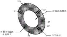
无线ECG模块15包括:数据获取模块41,其由具有嵌入式电路的柔性聚合物材料和电极贴片40构成。例如,数据获取模块41的嵌入式电路包括:数据获取电路26、微控制器28、机载存储器30、可再充电电池27和患者警告器29,如参照图3所描述的。例如,无线ECG模块15的电极贴片40由与最小一组(例如,3个)ECG电极23集成的透气多孔材料构成。在替换的实施例中,可以添加附加的ECG电极。附加地,电极贴片40也可以由硅、聚合物、泡沫、布料或类似材料构成。The
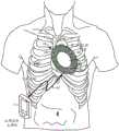
例如使用生物相容性粘合剂或电极贴片40的面向患者皮肤的底表面上的粘合剂表面来将无线ECG模块15的电极贴片40附接到患者的胸部。然而,电极贴片40可以由有自粘性的材料制成。如图5所示,无线ECG模块15位于心脏之上(例如,胸部左侧),其中电极贴片40包括以与本领域已知的3导联(LA,RA,LL)肢体导联配置类似的取向定位的ECG电极23(例如,3个)。电极23的取向还可以被放置在患者胸部的替代位置中,这取决于患者的解剖结构或诊断关注的心脏区域。一旦附接到患者,来自电极23的电信号就由数据获取模块41使用无线ECG模块15中的柔性线互连来接收,该柔性线互连将电极连接到数据获取模块41的嵌入式电路。The
来自电极23的ECG数据信号由数据获取模块41接收,并且由嵌入式电路进行处理,如先前参照图3和图4所描述的。例如,来自ECG电极23的数据信号被输入到ECG数据获取电路26,该ECG数据获取电路26包括放大电路、滤波电路和A/D电路,这些电路使用本领域已知的放大、滤波和A/D转换方法将模拟信号转换为数字信号。ECG data signals from
ECG数据获取电路26对ECG数据信号的处理产生数字数据波形,该数字数据波形被传递到微控制器28,该微控制器28对该数字波形进行分析,以识别指示患者异常状况的某些数字波形特性和阈值水平。微控制器28可以识别任何异常的心脏状况(例如,心律不齐、或指示缺血或心肌梗塞的ST段测量结果)。Processing of the ECG data signal by the ECG
如果确定存在任何异常状况,则微控制器28以警报或警告的方式将结果传输给患者,和/或经由无线通信链路42将结果传输给主模块7。当将警报或警告传输给患者时,微控制器28使用例如直接对患者皮肤的振动响应将信号传输给内部警告器29。当将结果经由无线通信链路42传输到主模块7时,主模块7的微控制器13可以使用有线连接和无线连接二者来建立通信连接以便关于所检测到的任何异常状况向患者、临床医生和护理人员传输生理数据、结果以及警报和/或警告,以及将生理数据存储在机载存储器22中,如先前参照图1和图2所描述的。If any abnormal condition is determined to exist, the
图6是根据本公开的实施例的包括连接到无线ECG模块的心前电极阵列的生理监测系统的示图。6 is an illustration of a physiological monitoring system including a precardiac electrode array connected to a wireless ECG module, according to an embodiment of the present disclosure.
图6的生理监测系统与图5的不同之处在于,图6的生理监测系统包括心前电极阵列(或组)53。可以将心前电极阵列53放置在接近ECG无线模块15的左右胸部的心前位置上。在本领域已知的是,心前位置是用以检测与中隔表面、左右心室的前壁以及左心室的侧壁相关联的心脏电活动的最佳位置。心前电极阵列53由与电极52(例如,5个或更多个电极)集成的透气多孔材料构成。然而,心前电极阵列53也可以由硅、聚合物、泡沫、布料或类似材料构成。使用例如生物相容性粘合剂或在心前电极阵列53的面向患者皮肤的底表面上的粘合剂表面来将心前电极阵列53附接到患者。然而,心前电极阵列53可以由有自粘性的材料制成。The physiological monitoring system of FIG. 6 differs from FIG. 5 in that the physiological monitoring system of FIG. 6 includes a precardiac electrode array (or set) 53 . The
如图6中所示,心前电极阵列53通过例如数据获取模块41中的外部连接端口(例如,ECG线缆端口)连接到无线ECG模块15。心前电极组53包括线缆50,其与直列式连接器51端接。该直列式连接器51被接纳在数据获取模块41的外部连接端口(例如,ECG线缆端口)中,该外部连接端口与嵌入式电路建立电连接(例如,与数据获取电路26的连接33),由此还在心前电极阵列53与无线ECG模块15之间建立连接。此配置提供了以下能力:获得用于与12导联记录类似的诊断数据的附加ECG数据,而不必移除无线ECG模块15的主电极(例如,3个)。心前电极阵列53的接地参考可以是远离心前组定位的远程电极(未示出)。替换地,可以从通过无线通信链路42接收的3导联组中得出地面参考,并且将其往回转换成模拟信号。一旦获得了附加的12导联ECG数据,在确定不再需要附加的诊断ECG数据之后,可以将心前电极阵列53断开连接。因此,在扩展的12导联ECG记录期间,不必移动或移除3导联组。As shown in FIG. 6 , the
在心前电极组53与无线ECG模块15之间的线缆50例如是电缆或其他类似接口线缆。一旦被附接,来自心前电极阵列53的电极52的电信号就被无线ECG模块15的数据获取模块41接收,并且数据信号由嵌入式电路处理,如先前参照图3和图4所描述的。The
例如,将来自电极52的数据信号输入到ECG数据获取电路26,该ECG数据获取电路26包括放大电路、滤波电路和A/D电路,这些电路使用本领域已知的放大、滤波和A/D转换方法将模拟信号转换为数字信号。ECG数据获取电路26对ECG数据信号的处理产生数字数据波形,该数字数据波形被传递到微控制器28,该微控制器28对该数字波形进行分析以识别指示患者异常状况的某些数字波形特性和阈值水平。微控制器28可以识别任何异常的心脏状况(例如,心律不齐、或指示缺血或心肌梗塞的ST段测量结果)。For example, the data signals from
如果确定存在任何异常状况,则微控制器28以警报或警告的方式将结果传输给患者,和/或经由无线通信链路42将结果传输给主模块7。当将警报或警告传输给患者时,微控制器28使用例如直接对患者皮肤的振动响应来将信号传输到内部警告器29。当将结果经由无线通信链路42传输到主模块7时,主模块7的微控制器13可以使用有线连接和无线连接二者来建立通信连接以便关于所检测到的任何异常状况向患者、临床医生和护理人员传输生理数据、结果以及的警报和/或警告,以及将生理数据存储在机载存储器22中,如先前参照图1和图2所描述的。If any abnormal condition is determined to exist, the
图7A是根据本公开的实施例的无线ECG模块的俯视图,并且图7B是根据本公开的实施例的无线ECG模块的侧视图。7A is a top view of a wireless ECG module according to an embodiment of the present disclosure, and FIG. 7B is a side view of the wireless ECG module according to an embodiment of the present disclosure.
如图7A所示,无线ECG模块15包括具有嵌入式电路的数据获取模块41和电极贴片40。数据获取模块41的嵌入式电路例如包括:数据获取电路26、微控制器28、机载存储器30、可再充电电池27和患者警告器29,如参照图3所描述的。数据获取模块41例如由柔性聚合物或其他类似材料构成。As shown in FIG. 7A , the
无线ECG模块15的电极贴片40由与最小一组(例如,3个)ECG电极23集成的透气多孔材料构成,类似于本领域已知的3通道肢体导联。然而,电极贴片也可以由硅、聚合物、泡沫、布料或类似材料构成。The
在该实施例中,ECG数据获取模块41可以是可重复使用的设备并且可拆卸地连接到电极贴片40,而电极贴片40(包括电极)是一次性的。ECG电极贴片40由属于柔性多孔结构的材料构成,以允许患者的皮肤“呼吸”。ECG数据获取模块41由诸如聚合物之类的柔性材料构成,该柔性材料是耐进水的,这允许患者在佩戴无线ECG模块15的同时进行淋浴或沐浴。该聚合物还可以是柔性的,以允许无线ECG模块15符合患者的身体。一旦ECG数据获取模块41被附接到新的电极贴片40,则三个(3个)电极就在ECG电极贴片下方通过柔性电路连接到数据获取模块41,以用于检测ECG电压信号。In this embodiment, the ECG
图7B图示了无线ECG无线模块15的侧视图,其中ECG数据获取模块41附接到ECG电极贴片40。如图7B中所示,电极23位于电极贴片40的外周上,其中电极的底表面被配置成与患者的皮肤进行接触。在该实施例中,ECG数据获取模块41是可重复使用的设备,并且可拆卸地连接到电极贴片40,而电极贴片40(包括电极)是一次性的,并且由属于柔性多孔结构的材料构成,以允许患者的皮肤“呼吸”。ECG数据获取模块41由柔性材料(例如,硅树脂或聚合物)构成,该柔性材料针对诸如湿气之类的环境危害来为数据获取模块41与电极贴片40之间的电互连提供保护。FIG. 7B illustrates a side view of the wireless
当患者处于生理监测的更高敏锐度水平内时,出于诊断目的,仍可能存在需要来在遍及一天过程的某些时间获得12导联ECG记录。还优选的是,临床医生不必移除用于3导联配置的电极来附接用于单独的12导联ECG记录器的电极。在这样的条件下,可以使用数据获取模块41中的线缆端口70将单独的心前ECG电极阵列53直接附接到患者和无线ECG模块15,以用于在更高的敏锐度监测期间在心前位置中提供附加的ECG记录。心前电极组53包括线缆50,其与直列式连接器51端接。该直列式连接器51被接纳在数据获取模块41的ECG线缆端口70中,该ECG线缆端口70与嵌入式电路建立电连接(例如,与数据获取电路26的连接33),由此也在心前电极阵列53与无线ECG模块15之间建立了连接。There may still be a need to obtain 12-lead ECG recordings at certain times throughout the course of the day for diagnostic purposes when the patient is within the higher acuity levels of physiological monitoring. It is also preferred that the clinician does not have to remove electrodes for the 3-lead configuration to attach electrodes for a separate 12-lead ECG recorder. Under such conditions, a separate pre-cardiac
ECG电极阵列53也可以在心脏康复活动期间被用来监测12导联ECG信号。一旦不再需要针对获得心前ECG波形的要求,就可以通过将线缆50的直列式连接器51与无线ECG模块的ECG线缆端口70断开连接来将心前ECG电极阵列53与无线ECG模块15断开连接。可以从患者移除心前电极阵列53,而留下无线ECG模块15的主3导联ECG贴片40被附接以进行附加的持续24小时(或更长时间)监测。The
在ECG无线模块15的ECG电极贴片40的另一个实施例中,ECG电极贴片40可以包括嵌入在柔性聚合物绝缘中的附加电极(例如,5个或更多个),以用于作为心前ECG电极阵列来检测ECG电压信号。In another embodiment of the
图8A是根据本公开的实施例的在数据获取模块与ECG模块的电极贴片之间的连接的侧视图。8A is a side view of connections between a data acquisition module and electrode patches of an ECG module, according to an embodiment of the present disclosure.
如图8A中所示,数据获取模块41与电极贴片40之间的连接包括:机械连接83、电连接80、84、以及用以针对进水进行保护的O形密封件81,这允许患者在佩戴无线ECG模块15的同时进行淋浴或沐浴。例如,机械连接是卡扣插塞机构83,该卡扣插塞机构83卡入电极贴片40的表面中,由此将数据获取模块41的底表面可拆卸地固定到电极贴片40的顶表面。电连接例如包括:公电连接器80(例如,3个),其通过与嵌入在电极贴片40中的线或柔性电路84进行接触来与电极贴片40的电极23建立电连接。电连接80、84允许来自ECG电极23的ECG信号被传输到ECG数据获取模块41。尽管图8A示出了公连接器80的使用,但是本申请的公开内容还构想的是,被用于在数据获取模块41与电极贴片40之间建立连接的连接器是母连接器,或者是公连接器和母连接器的组合。As shown in Figure 8A, the connections between the
为了针对进水对数据获取模块41与电极贴片40之间的电连接进行保护,在电连接器80周围并且在数据获取模块41与ECG电极贴片40的顶表面之间定位有O形密封件81。To protect the electrical connection between the
图8B是根据本公开的实施例的数据获取模块的电极连接的底视图。8B is a bottom view of electrode connections of a data acquisition module according to an embodiment of the present disclosure.
如图8B中所示,数据获取模块41的底表面包括:O形密封件81,其是同心的并且围绕电连接器80(例如,3个连接器),以便提供不透水密封,这保护了数据获取模块41与电极贴片40之间的电连接的完整性。由O形密封件81产生的不透水密封还允许患者在佩戴无线ECG模块15的同时进行淋浴或沐浴。As shown in Figure 8B, the bottom surface of the
电连接器80例如是公电连接器(例如,3个),其与电极贴片40的电极23建立电连接,从而与嵌入在电极贴片40中的线或柔性电路84进行接触。本申请的公开内容构想的是,被用于建立数据获取模块41与电极贴片40之间的连接的连接器可以是公连接器或母连接器,或者是公连接器和母连接器的组合。The
图9A是根据本公开的实施例的具有线缆和直列式连接器的心前电极阵列的俯视图。9A is a top view of a precordial electrode array with cables and in-line connectors, according to an embodiment of the present disclosure.
单独的心前ECG电极阵列53可以使用数据获取模块41中的线缆端口70直接附接到患者和无线ECG模块15,以用于在更高敏锐度监测期间在心前位置中提供附加的ECG记录。使用例如生物相容性粘合剂或在心前电极阵列53的面向患者皮肤的底表面上的粘合剂表面来将心前电极阵列53附接到患者的胸部。然而,心前电极阵列53可以由有自粘性的材料制成。通过数据获取模块41中的外部连接端口(例如,ECG线缆端口)将心前电极阵列53连接到无线ECG模块15的主电极组(例如,3个电极)。A separate precordial
心前电极阵列53由与电极52(例如,5个或更多个电极)集成的透气多孔材料构成。然而,心前电极阵列53也可以由硅、聚合物、泡沫、布料或类似材料构成。如图9A所示,心前电极阵列53包括与直列式连接器51端接的线缆50。该直列式连接器51包括一系列电触点93,该一系列电触点93被接纳在数据获取模块41的外部连接端口(例如,ECG线缆端口70)中,并且与嵌入式电路建立电连接(例如,与数据获取电路26的连接33),以及由此建立心前电极阵列53和无线ECG模块15之间的连接。此配置提供了以下能力:获得附加的ECG数据作为与12导联记录类似的诊断数据,而不必移除无线ECG模块15的主电极(例如,3个)。
直列式连接器51还包括:围绕ECG线缆50的、同心的密封件92,以用于提供不透水密封,由此在直列式连接器被接纳在数据获取模块41的外部连接端口(例如,ECG线缆端口70)中时,保护数据获取模块41与心前电极阵列53之间的电连接的完整性。使密封件91集成在ECG线缆50内而不是在连接器腔内具有O形环可以通过避免多用途配置来改善密封件的可靠性。The in-
一旦在数据获取模块41与心前电极阵列53之间建立连接,就使用诸如键式扭锁91之类的锁定机构将直列式连接器51牢固地保持在适当的位置。当将键式扭锁91插入在数据获取模块41的外部连接端口中时,该键式扭锁91被扭转(例如,沿顺时针方向90°)并且在开槽的槽内(例如,在外部连接端口中)对准。通过保持直列式连接器51的应变消除部分90,将直列式连接器51引导到数据获取模块41的外部连接端口中的适当位置,这防止损坏心前电极阵列53和线缆50。该应变消除部分90被集成到ECG线缆50中,这也可以提供附加保护以免受进水。Once the connection is established between the
ECG电极阵列53可以在心脏康复活动期间被用来监测12导联ECG信号。一旦不再需要获得心前ECG波形的要求,就可以通过将线缆50的直列式连接器51与无线ECG模块15的ECG线缆端口70断开连接来将心前ECG电极阵列53与无线ECG模块15断开连接。可以从患者移除心前电极阵列53,留下无线ECG模块15的主3导联ECG贴片40被附接以进行附加的持续24小时(或更长时间)监测。
图9B是根据本公开的实施例的用于心前电极阵列的ECG线缆的键式扭锁的截面图。9B is a cross-sectional view of a keyed twist lock for an ECG cable of a precordial electrode array according to an embodiment of the present disclosure.
直列式连接器51一旦处于适当位置并且在数据获取模块41与心前电极阵列53之间建立连接,就使用集成的键式扭锁91将其牢固地保持在适当的位置。Once the in-
如图9B所示,键式扭锁91与线缆50集成,类似于密封件92。键式扭锁91插入到数据获取模块41的外部连接端口(例如,ECG线缆端口70)的开槽的槽中,并且例如在顺时针方向上扭转90°,并且在开槽的槽中对准,由此使直列式连接器51与数据获取模块41之间的连接牢固。一旦不再需要获得心前ECG波形的要求,就可以通过将被插入到外部连接端口的开槽的槽中的键式扭锁91在逆时针方向上再次扭转例如90°,来将心前ECG电极阵列53与无线ECG模块15断开连接,由此释放直列式连接器51与数据获取模块41之间的连接。As shown in FIG. 9B , a
图10是根据本公开的实施例的数据获取模块与心前电极阵列之间的连接的侧视图。10 is a side view of a connection between a data acquisition module and a precordial electrode array in accordance with an embodiment of the present disclosure.
心前电极阵列53包括:线缆50,其与直列式连接器51端接。如图10中所示,直列式连接器51包括一系列电触点93,它们被接纳在数据获取模块41的ECG线缆端口70中。该ECG线缆端口70包括连接器腔98,其具有一系列压缩触点99,当直列式连接器51完全插入到数据获取模块41的连接器腔98中时,该一系列压缩触点99与一系列电触点93对准。当直列式连接器51完全插入到数据获取模块41的连接器腔98中时,直列式连接器51与数据获取模块41的嵌入式电路建立电连接(例如,与数据获取电路26的连接33),这进而在心前电极阵列53与无线ECG模块15之间建立连接。这种配置提供了以下能力:获得用于与12导联记录类似的诊断数据的附加ECG数据,而不必移除无线ECG模块15的主电极(例如,3个)。The
直列式连接器51还包括围绕ECG线缆50的、同心的集成密封件92,以用于提供不透水密封,由此在直列式连接器51被接纳在数据获取模块41的ECG线缆端口70中时,保护数据获取模块41与心前电极阵列53之间的电连接的完整性。使密封件92集成在ECG线缆50内而不是在连接器腔内具有O形环可以通过避免多用途配置来改善密封件的可靠性。The in-
一旦在数据获取模块41与心前电极阵列53之间建立连接,就使用诸如键式扭锁91之类的锁定机构将直列式连接器51牢固地保持在适当的位置,该锁定机构在被插入到数据获取模块41的ECG线缆端口70中时被扭转(例如,90°)并且在开槽的槽中对准。通过保持直列式连接器51的应变消除部分90,将直列式连接器51引导到ECG线缆端口70和连接器腔98中,这防止损坏心前电极阵列53和线缆50。该应变消除部分90被集成到ECG线缆50中,这也可以提供附加保护以免受进水。Once the connection is established between the
图11A和11B分别是ECG模块和心前阵列上的可调节电极的俯视图。11A and 11B are top views of adjustable electrodes on the ECG module and precordial array, respectively.
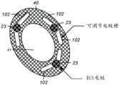
每个患者具有不同的解剖结构(例如,身体大小和心脏取向),并且可能需要监测不同的心脏状况。因此,可能有需要将每个ECG电极的位置调整为特定于每个患者的应用。如图11A中所示,无线ECG模块15的该实施例包括数据获取模块41,其由具有嵌入式电路的柔性聚合物材料和电极贴片40构成。数据获取模块41的嵌入式电路例如包括:数据获取电路26、微控制器28、机载存储器30、可再充电电池27和患者警告器29,如参照图3所描述的。Each patient has different anatomy (eg, body size and cardiac orientation) and may require monitoring of different cardiac conditions. Therefore, it may be necessary to adjust the position of each ECG electrode to be specific to each patient's application. As shown in FIG. 11A , this embodiment of the
无线ECG模块15的电极贴片40例如由与最小一组(例如,3个)ECG电极23集成的透气多孔材料构成。在替换的实施例中,可以添加附加的ECG电极。附加地,电极贴片40也可以由硅、聚合物、泡沫、布料或类似材料构成。如图11A中所示,电极贴片40包括可调节电极槽102。每个ECG电极23的位置可以在电极贴片40中的每一个电极槽102内进行调节。例如,用来调节每个ECG电极23的一种可能方法将是要在每个ECG电极23的对应可调节电极槽102内提供对每个ECG电极23的调节,并且依赖于对围绕ECG电极23的主体的电极贴片40的柔性聚合物或电极粘合剂进行压缩以维持稳定性。The
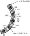
如图11B中所示,心前电极阵列53的该实施例包括可调节电极槽103。心前电极阵列53由与电极52(例如,5个或更多个电极)集成的透气多孔材料构成。然而,心前电极阵列53也可以由硅、聚合物、泡沫、布料或类似材料构成。每个ECG电极52的位置可以在心前电极阵列53中的每个ECG电极52的对应电极槽103内被调整。例如,可以通过依赖于对围绕ECG电极53的主体的柔性聚合物或电极粘合剂进行压缩以维持稳定性来在每个ECG电极52的对应可调节电极槽103内调节每个ECG电极52。As shown in FIG. 11B , this embodiment of the
图12A和12B示出了本公开的实施例,其中ECG数据获取模块41与电极贴片40集成,使得整个ECG无线设备15是一次性的。无线ECG模块15例如由与最小一组(例如,3个)ECG电极23集成的透气多孔材料构成。在替换的实施例中,可以添加附加的ECG电极。附加地,无线ECG模块15也可以由硅、聚合物、泡沫、布料或类似材料构成。12A and 12B illustrate an embodiment of the present disclosure in which the ECG
如图12B中所示,电极23位于电极贴片40的外周上,其中电极的底表面被配置成与患者的皮肤进行接触。在该实施例中,ECG数据获取模块41和电极贴片40是一次性的,并且无线ECG模块15的数据获取模块41包括嵌入式电路112。该嵌入式电路例如包括数据获取电路26、微控制器28、机载存储器30、可再充电电池27和患者警告器29,如参照图3所描述的。As shown in FIG. 12B,
如图12B中所示,通过嵌入在无线ECG模块15中的线或柔性电路110在电极贴片40的电极23与嵌入式电路112之间建立电连接。该电连接允许来自ECG电极23的ECG信号被传输到ECG数据获取模块41的嵌入式电路110。As shown in FIG. 12B , an electrical connection is established between the
无线ECG模块15的图12A和12B的实施例可以简化互连设计,并且将消除对可再充电电源的要求(即,必须在两个ECG数据获取模块之间置换出)。从临床角度来看,完全一次性的设备可以通过减少有时可能是由于与可重复使用的设备相关的不正确的清洁方法所引起的感染的风险来改善患者的预后。The embodiment of Figures 12A and 12B of the
图13是根据本公开的实施例的包括连接到主模块的心前电极阵列的生理监测系统的示图。13 is an illustration of a physiological monitoring system including a precordial electrode array connected to a main module, according to an embodiment of the present disclosure.
图13的生理监测系统与图6的生理监测系统的不同之处在于心前电极阵列(或组)53连接到主模块7而不是连接到无线ECG模块15。可以将心前电极阵列53(例如,5个或更多个电极)放置在接近ECG无线模块15的左右胸部的心前位置之上。心前电极阵列53由与电极52集成的透气多孔材料构成。然而,心前电极阵列53也可以由硅、聚合物、泡沫、布料或类似材料构成。The physiological monitoring system of FIG. 13 differs from the physiological monitoring system of FIG. 6 in that the precardiac electrode array (or set) 53 is connected to the
使用例如生物相容性粘合剂或心前电极阵列53的面向患者皮肤的底表面上的粘合剂表面来将心前电极阵列53附接到患者。然而,心前电极阵列53可以由有自粘性的材料制成。The
通过被插入到主模块7中的外部连接端口(例如,线缆端口)中的线缆120将心前电极阵列53连接到主模块7。心前电极组53包括线缆120,其与直列式连接器端接。该直列式连接器被接纳在主模块7的外部连接端口中,由此在心前电极阵列53与主模块7的电路之间建立连接。该配置提供了以下能力:获得用于与12导联记录类似的诊断数据的附加ECG数据,而不必移除无线ECG模块15的主电极(例如,3个)。一旦获得附加的12导联ECG数据,在确定不再需要附加的诊断ECG数据之后,就可以将心前电极阵列53断开连接。The
心前电极组53与主模块7之间的线缆120例如是电缆或其他类似的接口线缆。一旦被附接,来自心前电极阵列53的电极52的电信号就被主模块7接收,数据信号由主模块7的电路处理,如先前参照图1和图2所描述的。The
例如,将来自电极52的数据信号输入到ECG数据获取电路9,该ECG数据获取电路9包括放大电路、滤波电路和A/D电路,这些电路使用本领域已知的放大、滤波和A/D转换方法将模拟信号转换为数字信号。ECG数据获取电路9对ECG数据信号的处理产生数字数据波形,该数字数据波形被传递到微控制器12,该微控制器12对该数字波形进行分析以识别指示患者异常状况的某些数字波形特性和阈值水平。微控制器12可以识别任何异常的心脏状况(例如,心律不齐、或指示缺血或心肌梗塞的ST段测量结果)。For example, the data signals from
附加地,微控制器13包括通信接口电路,其用于使用有线连接和无线连接两者来建立与各种设备和网络的通信连接,以便传输生理数据、由微控制器12进行分析的结果,以及就检测到的任何异常状况而言向患者、临床医生和护理人员传输警报和/或警告,以及将生理数据存储在机载存储器22中。Additionally, the
图14是根据本公开的实施例的主模块与心前电极阵列之间的连接的侧视图。14 is a side view of the connection between the main module and the precordial electrode array according to an embodiment of the present disclosure.
心前电极阵列53包括线缆120,其与直列式连接器138端接。如图14中所示,直列式连接器138包括一系列电触点134,该一系列电触点134被接纳在主模块7的线缆端口137中。线缆端口137包括连接器腔130,其具有一系列压缩触点131,当将直列式连接器138完全插入到主模块7的连接器腔130中时,该一系列压缩触点131与一系列电触点134对准。当直列式连接器138被完全插入到主模块7的连接器腔130中时,直列式连接器138与主模块7的电路建立电连接。
直列式连接器138还包括集成密封件135,其例如围绕ECG线缆120是同心的,以便提供不透水密封,由此当直列式连接器138被接纳在线缆端口137中时保护心前电极阵列53与主模块7之间的电连接的完整性。使密封件135集成到ECG线缆120内而不是在连接器腔130内具有O形环可以通过避免多用途配置来改善密封件135的可靠性。The in-
一旦在主模块7与心前电极阵列53之间建立了连接,就使用诸如键式扭锁132之类的锁定机构将直列式连接器138牢固地保持在适当的位置。将键式扭锁132插入主模块7的ECG线缆端口137中,并且然后将其扭转(例如,90°),并且在开槽的槽内(例如,在连接器腔中)对准。直列式连接器138被引导到线缆端口137和连接器腔130中(即,用于通过保持直列式连接器138的应变消除部分136来在主模块7与心前电极阵列53之间建立连接,这防止损坏心前电极阵列53和线缆120)。应变消除部分136被集成到ECG线缆120中,这也可以提供附加保护以免受进水。Once the connection is established between the
本申请的本公开内容中所描述的主题相对于常规的患者监测设备和系统提供了许多技术改进,其例如包括:通过提供简化的ECG电极放置、可拆卸的心前电极阵列、产品子系统之间的无线通信(其消除了ECG电极与生理监测仪之间的线)所致的患者在与其疗养和康复相关联的非固定活动期间的改进预后,以及与抗扰度和可靠性有关的改进性能。The subject matter described in the present disclosure of the present application provides many technical improvements over conventional patient monitoring devices and systems, including, for example, by providing simplified ECG electrode placement, detachable precardiac electrode arrays, integration of product subsystems Improved patient outcomes during ambulatory activities associated with their convalescence and rehabilitation due to wireless communication between ECG electrodes, which eliminates wires between ECG electrodes and physiological monitors, and improvements related to noise immunity and reliability performance.
相对于常规的患者监测设备和系统的技术改进还包括电极阵列与主模块和无线ECG电极阵列的互连,其可以被配置为具有直列式连接。附加地,电极阵列和无线ECG模块具有调整各个电极位置的能力,这可以允许将特定的心脏向量应用于每个患者。此外,无线ECG模块可以包括一次性组件和电路。The technical improvement over conventional patient monitoring devices and systems also includes the interconnection of the electrode array with the main module and the wireless ECG electrode array, which can be configured with in-line connections. Additionally, the electrode array and wireless ECG module have the ability to adjust individual electrode positions, which may allow specific cardiac vectors to be applied to each patient. Additionally, the wireless ECG module may include disposable components and circuits.
本公开可以被实现为在非暂时性计算机可读记录介质上的装置、系统、集成电路和计算机程序的任何组合。微控制器可以被实现为实行无线ECG模块和主模块的一部分或全部功能的集成电路(IC)、专用集成电路(ASIC)或大规模集成电路(LSI)、系统LSI、超级LSI或超LSI组件。The present disclosure can be implemented as any combination of an apparatus, a system, an integrated circuit and a computer program on a non-transitory computer-readable recording medium. The microcontroller may be implemented as an integrated circuit (IC), an application specific integrated circuit (ASIC) or a large scale integrated circuit (LSI), a system LSI, a super LSI or a super LSI component that performs part or all of the functions of the wireless ECG module and the main module .
本公开的无线ECG模块和主模块的每一个组件可以使用许多单功能组件来实现,或者可以是使用上述技术所集成的一个组件。结合本文中的公开内容进行描述的各种说明性电路和模块可以利用被设计成实行本文中所描述的功能的通用处理器、数字信号处理器(DSP)、专用集成电路(ASIC)、现场可编程门阵列(FPGA)或其他可编程逻辑器件、分立门或晶体管逻辑、分立硬件组件或其任何组合来实现或者实行。通用处理器可以是微处理器,但是在替换方案中,处理器可以是任何常规的处理器、控制器、微控制器或状态机。处理器也可以被实现为计算设备的组合,例如,DSP和微处理器的组合、多个微处理器、结合DSP核的一个或多个微处理器、或任何其他这样的配置。在某些情况下,处理器可以与存储器进行电子通信,其中存储器存储可由处理器执行的指令。Each component of the wireless ECG module and main module of the present disclosure may be implemented using many single-function components, or may be one component integrated using the techniques described above. The various illustrative circuits and modules described in connection with the disclosure herein may utilize general-purpose processors, digital signal processors (DSPs), application-specific integrated circuits (ASICs), field-available processors designed to perform the functions described herein. A programmed gate array (FPGA) or other programmable logic device, discrete gate or transistor logic, discrete hardware components, or any combination thereof is implemented or implemented. A general-purpose processor may be a microprocessor, but in the alternative, the processor may be any conventional processor, controller, microcontroller, or state machine. A processor may also be implemented as a combination of computing devices, eg, a combination of a DSP and a microprocessor, multiple microprocessors, one or more microprocessors combined with a DSP core, or any other such configuration. In some cases, the processor may be in electronic communication with memory, where the memory stores instructions executable by the processor.
本公开包括在无线ECG模块和主模块中使用计算机程序或算法。该程序或算法可以存储在非暂时性计算机可读介质上,以便使诸如微控制器之类的计算机执行图2和图4中描述的步骤。计算机程序(也可以被称为程序、软件、软件应用、应用、组件或代码)包括用于可编程处理器的机器指令,并且可以以高级过程语言、面向对象的编程语言、功能性编程语言、逻辑编程语言或汇编语言或机器语言来实现。术语计算机可读记录介质指代被用来向可编程数据处理器提供机器指令或数据的任何计算机程序产品、装置或设备(诸如磁盘、光盘、固态存储设备、存储器和可编程逻辑器件(PLD)),该可编程数据处理器包括计算机可读记录介质,该计算机可读记录介质接收作为计算机可读信号的机器指令。The present disclosure includes the use of computer programs or algorithms in the wireless ECG module and main module. The program or algorithm may be stored on a non-transitory computer readable medium to cause a computer, such as a microcontroller, to perform the steps described in FIGS. 2 and 4 . A computer program (which may also be referred to as a program, software, software application, application, component, or code) includes machine instructions for a programmable processor, and can be written in a high-level procedural language, object-oriented programming language, functional programming language, Logic programming language or assembly language or machine language to implement. The term computer-readable recording medium refers to any computer program product, apparatus, or device used to provide machine instructions or data to a programmable data processor (such as magnetic disks, optical disks, solid-state storage devices, memories, and programmable logic devices (PLDs) ), the programmable data processor including a computer-readable recording medium receiving machine instructions as computer-readable signals.
作为示例,计算机可读介质可以包括RAM、ROM、EEPROM、CD-ROM或其他光盘存储装置、磁盘存储装置或其他磁存储设备,或可以被用来承载或存储期望的计算机可读程序代码的任何其他介质,该期望的计算机可读程序代码是以指令或数据结构的形式,并且可以由通用或专用计算机、或者通用或专用处理器来访问。如在本文中使用的磁盘和盘包括紧凑盘(CD)、激光盘、光盘、数字多功能盘(DVD)、软盘和蓝光盘,其中磁盘通常磁性地再现数据,而光盘利用激光来光学地再现数据。以上内容的组合也被包括在计算机可读介质的范围内。By way of example, a computer-readable medium may include RAM, ROM, EEPROM, CD-ROM or other optical disk storage, magnetic disk storage or other magnetic storage devices, or any other device that may be used to carry or store the desired computer-readable program code Other media, the desired computer readable program code is in the form of instructions or data structures and can be accessed by a general purpose or special purpose computer, or a general purpose or special purpose processor. Disk and disc, as used herein, includes compact disc (CD), laser disc, optical disc, digital versatile disc (DVD), floppy disk, and blu-ray disc, where disks typically reproduce data magnetically, while discs reproduce data optically with lasers data. Combinations of the above are also included within the scope of computer-readable media.
本申请的公开内容的主题仅被提供为患者监测设备和系统的示例。除了上述患者监测装置和系统的特征之外,还构想到其他特征或变化。构想到的是,可以利用任何新出现的技术来完成本公开的组件的实现方式,该新出现的技术可以代替任何以上实现的技术。The subject matter of the present disclosure is provided merely as an example of patient monitoring devices and systems. In addition to the features of the patient monitoring device and system described above, other features or variations are also contemplated. It is contemplated that implementations of the components of the present disclosure may be accomplished using any emerging technology, which may be substituted for any of the above-implemented technologies.
上面的描述提供了示例,并且不限制权利要求中阐述的范围、可适用性或配置。在不脱离本公开的精神和范围的情况下,可以对所讨论的元件的功能和布置进行改变。各种实施例可以酌情省略、替代或添加各种过程或组件。例如,关于某些实施例描述的特征可以在其他实施例中被组合。The above description provides examples, and does not limit the scope, applicability, or configuration set forth in the claims. Changes may be made in the function and arrangement of elements discussed without departing from the spirit and scope of the disclosure. Various embodiments may omit, substitute, or add various procedures or components as appropriate. For example, features described with respect to some embodiments may be combined in other embodiments.
提供本公开的先前描述以使本领域技术人员能够制造或使用本公开。对本公开的各种修改将对本领域技术人员是容易地显而易见的,并且本文中定义的一般原理可以在不脱离本公开的精神或范围的情况下应用于其他变化。遍及本公开,术语“示例”指示示例或实例,并且不暗示或要求对所提到的示例的任何偏好。因此,本公开将不被限于本文中所描述的示例和设计,而是要符合与本文中所公开的原理和新颖特征一致的最广范围。The previous description of the present disclosure is provided to enable any person skilled in the art to make or use the present disclosure. Various modifications to the present disclosure will be readily apparent to those skilled in the art, and the generic principles defined herein may be applied to other changes without departing from the spirit or scope of the present disclosure. Throughout this disclosure, the term "example" indicates an example or instance, and does not imply or require any preference for the mentioned example. Thus, the present disclosure is not to be limited to the examples and designs described herein but is to be accorded the widest scope consistent with the principles and novel features disclosed herein.
Claims (58)
Translated fromChineseApplications Claiming Priority (3)
| Application Number | Priority Date | Filing Date | Title |
|---|---|---|---|
| US201762564104P | 2017-09-27 | 2017-09-27 | |
| US62/564104 | 2017-09-27 | ||
| PCT/US2018/052803WO2019067507A1 (en) | 2017-09-27 | 2018-09-26 | Device and system for providing physiological data monitoring of patients |
Publications (1)
| Publication Number | Publication Date |
|---|---|
| CN111432721Atrue CN111432721A (en) | 2020-07-17 |
Family
ID=63915360
Family Applications (1)
| Application Number | Title | Priority Date | Filing Date |
|---|---|---|---|
| CN201880076622.9APendingCN111432721A (en) | 2017-09-27 | 2018-09-26 | Physiological monitoring device and system for providing monitoring of physiological data of a patient |
Country Status (4)
| Country | Link |
|---|---|
| US (1) | US20200268250A1 (en) |
| EP (2) | EP4282333B1 (en) |
| CN (1) | CN111432721A (en) |
| WO (1) | WO2019067507A1 (en) |
Families Citing this family (3)
| Publication number | Priority date | Publication date | Assignee | Title |
|---|---|---|---|---|
| US20220304608A1 (en)* | 2021-03-25 | 2022-09-29 | Umana Medical Technologies Ltd. | Multifunctional electrophysiological monitoring system |
| CN117940064A (en)* | 2021-09-08 | 2024-04-26 | 深圳迈瑞生物医疗电子股份有限公司 | Wearable mobile monitoring device, monitoring system and data transmission method |
| US20250099006A1 (en)* | 2023-09-26 | 2025-03-27 | Bittium Biosignals Oy | Bio-signal receiving device, flexible patch electrode structure, bio-signal apparatus and connection method of bio-signal apparatus |
Citations (5)
| Publication number | Priority date | Publication date | Assignee | Title |
|---|---|---|---|---|
| CN101583305A (en)* | 2006-03-03 | 2009-11-18 | 理疗波公司 | Physiologic monitoring systems and methods |
| US20110125040A1 (en)* | 2008-03-10 | 2011-05-26 | Koninklijke Philips Electronics N.V. | Wireless ecg monitoring system |
| US20130225967A1 (en)* | 2012-02-29 | 2013-08-29 | Anthony Esposito | Small wireless portable ekg system |
| CN104490388A (en)* | 2014-12-16 | 2015-04-08 | 无锡市健维仪器有限公司 | Extensible human health remote recording, monitoring and diagnosis system |
| KR20170041595A (en)* | 2015-10-07 | 2017-04-17 | 주식회사 케이헬쓰웨어 | Wearable and wireless 12 channel electrocardiograph system |
Family Cites Families (12)
| Publication number | Priority date | Publication date | Assignee | Title |
|---|---|---|---|---|
| US5788633A (en)* | 1997-01-28 | 1998-08-04 | Hewlett-Packard Company | ECG electrode strip with elongated slots |
| US6870109B1 (en)* | 2001-06-29 | 2005-03-22 | Cadwell Industries, Inc. | System and device for reducing signal interference in patient monitoring systems |
| US7444177B2 (en)* | 2003-03-04 | 2008-10-28 | Alireza Nazeri | EKG recording accessory system (EKG RAS) |
| US8688189B2 (en)* | 2005-05-17 | 2014-04-01 | Adnan Shennib | Programmable ECG sensor patch |
| US8660630B2 (en)* | 2006-12-27 | 2014-02-25 | Los Angeles Biomedical Research Institute At Harbor-Ucla Medical Center | ECG leads system for newborn ECG screening |
| EP3021742A4 (en)* | 2013-07-18 | 2017-03-01 | Nuline Sensors, LLC | Medical data acquisition systems and methods for monitoring and diagnosis |
| US9433367B2 (en)* | 2013-09-25 | 2016-09-06 | Bardy Diagnostics, Inc. | Remote interfacing of extended wear electrocardiography and physiological sensor monitor |
| US9615794B2 (en)* | 2013-12-03 | 2017-04-11 | Qualcomm Incorporated | Method, devices and systems for sensor with removable nodes |
| US9320446B2 (en)* | 2013-12-09 | 2016-04-26 | Medtronic, Inc. | Bioelectric sensor device and methods |
| US12070601B2 (en)* | 2014-03-28 | 2024-08-27 | Pinnacle Bionics. Inc. | Stimulation system for exercising diaphragm and method of operation thereof |
| AU2016261383A1 (en)* | 2015-05-12 | 2017-11-30 | Monitra Healthcare Private Limited | Wire-free monitoring device for acquiring, processing and transmitting physiological signals |
| US10342445B2 (en)* | 2016-11-03 | 2019-07-09 | Medtronic Monitoring, Inc. | Method and apparatus for detecting electrocardiographic abnormalities based on monitored high frequency QRS potentials |
- 2018
- 2018-09-26CNCN201880076622.9Apatent/CN111432721A/enactivePending
- 2018-09-26WOPCT/US2018/052803patent/WO2019067507A1/ennot_activeCeased
- 2018-09-26USUS16/649,880patent/US20200268250A1/enactivePending
- 2018-09-26EPEP23203644.2Apatent/EP4282333B1/enactiveActive
- 2018-09-26EPEP18789739.2Apatent/EP3687393B1/enactiveActive
Patent Citations (5)
| Publication number | Priority date | Publication date | Assignee | Title |
|---|---|---|---|---|
| CN101583305A (en)* | 2006-03-03 | 2009-11-18 | 理疗波公司 | Physiologic monitoring systems and methods |
| US20110125040A1 (en)* | 2008-03-10 | 2011-05-26 | Koninklijke Philips Electronics N.V. | Wireless ecg monitoring system |
| US20130225967A1 (en)* | 2012-02-29 | 2013-08-29 | Anthony Esposito | Small wireless portable ekg system |
| CN104490388A (en)* | 2014-12-16 | 2015-04-08 | 无锡市健维仪器有限公司 | Extensible human health remote recording, monitoring and diagnosis system |
| KR20170041595A (en)* | 2015-10-07 | 2017-04-17 | 주식회사 케이헬쓰웨어 | Wearable and wireless 12 channel electrocardiograph system |
Also Published As
| Publication number | Publication date |
|---|---|
| WO2019067507A1 (en) | 2019-04-04 |
| EP4282333B1 (en) | 2025-03-26 |
| US20200268250A1 (en) | 2020-08-27 |
| EP3687393A1 (en) | 2020-08-05 |
| EP4282333A2 (en) | 2023-11-29 |
| EP4282333A3 (en) | 2024-02-21 |
| EP3687393B1 (en) | 2023-11-01 |
Similar Documents
| Publication | Publication Date | Title |
|---|---|---|
| US12109022B2 (en) | Wireless patient monitoring device | |
| US11653867B2 (en) | Contactless electric cardiogram system | |
| US20210327576A1 (en) | Common display unit for a plurality of cableless medical sensors | |
| AU2020201342A1 (en) | Head harness & wireless EEG monitoring system | |
| EP4282333B1 (en) | Device and system for providing physiological data monitoring of patients | |
| EP3821799B1 (en) | Three-lead electrocardiography monitoring method and device | |
| US20230108418A1 (en) | A modular connector system and a modular connector having two or more detachably secured housings | |
| Navaneethan et al. | Healthcare Measurement of ECG and Body Temperature Signals Using Android Mobile | |
| Navaneethan et al. | Healthcare Measurement Of ECG Signals Using Android Mobile | |
| HK1222307B (en) | Contactless electrocardiography |
Legal Events
| Date | Code | Title | Description |
|---|---|---|---|
| PB01 | Publication | ||
| PB01 | Publication | ||
| SE01 | Entry into force of request for substantive examination | ||
| SE01 | Entry into force of request for substantive examination |