CN111432681A - Tourniquet with rotatable buckle assembly - Google Patents
Tourniquet with rotatable buckle assemblyDownload PDFInfo
- Publication number
- CN111432681A CN111432681ACN201880033748.8ACN201880033748ACN111432681ACN 111432681 ACN111432681 ACN 111432681ACN 201880033748 ACN201880033748 ACN 201880033748ACN 111432681 ACN111432681 ACN 111432681A
- Authority
- CN
- China
- Prior art keywords
- tourniquet
- buckle
- buckle frame
- hook
- frame
- Prior art date
- Legal status (The legal status is an assumption and is not a legal conclusion. Google has not performed a legal analysis and makes no representation as to the accuracy of the status listed.)
- Granted
Links
- 239000000463materialSubstances0.000claimsdescription4
- 230000004888barrier functionEffects0.000claimsdescription3
- 239000004744fabricSubstances0.000claims3
- 239000004753textileSubstances0.000claims2
- 210000003414extremityAnatomy0.000description10
- 208000014674injuryDiseases0.000description5
- 210000002414legAnatomy0.000description5
- 208000032843HemorrhageDiseases0.000description4
- 230000000740bleeding effectEffects0.000description4
- 230000008733traumaEffects0.000description4
- 230000008901benefitEffects0.000description3
- 230000017531blood circulationEffects0.000description3
- 238000000034methodMethods0.000description3
- 208000027418Wounds and injuryDiseases0.000description2
- 239000008280bloodSubstances0.000description2
- 210000004369bloodAnatomy0.000description2
- 238000013461designMethods0.000description2
- 230000004048modificationEffects0.000description2
- 238000012986modificationMethods0.000description2
- 206010060964Arterial haemorrhageDiseases0.000description1
- 206010021138Hypovolaemic shockDiseases0.000description1
- 239000004677NylonSubstances0.000description1
- 239000004743PolypropyleneSubstances0.000description1
- 230000009286beneficial effectEffects0.000description1
- 230000006378damageEffects0.000description1
- 230000001934delayEffects0.000description1
- 230000003111delayed effectEffects0.000description1
- 238000011161developmentMethods0.000description1
- 230000018109developmental processEffects0.000description1
- 238000006073displacement reactionMethods0.000description1
- 238000003780insertionMethods0.000description1
- 230000037431insertionEffects0.000description1
- 238000004519manufacturing processMethods0.000description1
- 230000007246mechanismEffects0.000description1
- 239000002184metalSubstances0.000description1
- 239000003607modifierSubstances0.000description1
- 229920001778nylonPolymers0.000description1
- -1polypropylenePolymers0.000description1
- 229920001155polypropylenePolymers0.000description1
- 230000008569processEffects0.000description1
- 238000000926separation methodMethods0.000description1
- 238000009958sewingMethods0.000description1
- 206010040560shockDiseases0.000description1
- 238000012549trainingMethods0.000description1
- 230000007306turnoverEffects0.000description1
- 210000000689upper legAnatomy0.000description1
Images


Classifications
- A—HUMAN NECESSITIES
- A61—MEDICAL OR VETERINARY SCIENCE; HYGIENE
- A61B—DIAGNOSIS; SURGERY; IDENTIFICATION
- A61B17/00—Surgical instruments, devices or methods
- A61B17/12—Surgical instruments, devices or methods for ligaturing or otherwise compressing tubular parts of the body, e.g. blood vessels or umbilical cord
- A61B17/132—Tourniquets
- A61B17/1322—Tourniquets comprising a flexible encircling member
- A61B17/1325—Tourniquets comprising a flexible encircling member with means for applying local pressure
- A—HUMAN NECESSITIES
- A44—HABERDASHERY; JEWELLERY
- A44B—BUTTONS, PINS, BUCKLES, SLIDE FASTENERS, OR THE LIKE
- A44B11/00—Buckles; Similar fasteners for interconnecting straps or the like, e.g. for safety belts
- A44B11/005—Buckles combined with other articles, e.g. with receptacles
- A—HUMAN NECESSITIES
- A44—HABERDASHERY; JEWELLERY
- A44B—BUTTONS, PINS, BUCKLES, SLIDE FASTENERS, OR THE LIKE
- A44B11/00—Buckles; Similar fasteners for interconnecting straps or the like, e.g. for safety belts
- A44B11/006—Attachment of buckle to strap
- A—HUMAN NECESSITIES
- A44—HABERDASHERY; JEWELLERY
- A44B—BUTTONS, PINS, BUCKLES, SLIDE FASTENERS, OR THE LIKE
- A44B11/00—Buckles; Similar fasteners for interconnecting straps or the like, e.g. for safety belts
- A44B11/02—Buckles; Similar fasteners for interconnecting straps or the like, e.g. for safety belts frictionally engaging surface of straps
- A44B11/06—Buckles; Similar fasteners for interconnecting straps or the like, e.g. for safety belts frictionally engaging surface of straps with clamping devices
- A44B11/12—Buckles; Similar fasteners for interconnecting straps or the like, e.g. for safety belts frictionally engaging surface of straps with clamping devices turnable clamp
- A44B11/125—Buckles; Similar fasteners for interconnecting straps or the like, e.g. for safety belts frictionally engaging surface of straps with clamping devices turnable clamp with strap tightening means
- A—HUMAN NECESSITIES
- A44—HABERDASHERY; JEWELLERY
- A44B—BUTTONS, PINS, BUCKLES, SLIDE FASTENERS, OR THE LIKE
- A44B11/00—Buckles; Similar fasteners for interconnecting straps or the like, e.g. for safety belts
- A44B11/02—Buckles; Similar fasteners for interconnecting straps or the like, e.g. for safety belts frictionally engaging surface of straps
- A44B11/18—Strap held by threading through linked rings
- A—HUMAN NECESSITIES
- A44—HABERDASHERY; JEWELLERY
- A44B—BUTTONS, PINS, BUCKLES, SLIDE FASTENERS, OR THE LIKE
- A44B11/00—Buckles; Similar fasteners for interconnecting straps or the like, e.g. for safety belts
- A44B11/25—Buckles; Similar fasteners for interconnecting straps or the like, e.g. for safety belts with two or more separable parts
- A44B11/28—Buckles; Similar fasteners for interconnecting straps or the like, e.g. for safety belts with two or more separable parts with hooks engaging end-pieces on the strap
- A—HUMAN NECESSITIES
- A61—MEDICAL OR VETERINARY SCIENCE; HYGIENE
- A61B—DIAGNOSIS; SURGERY; IDENTIFICATION
- A61B17/00—Surgical instruments, devices or methods
- A61B17/12—Surgical instruments, devices or methods for ligaturing or otherwise compressing tubular parts of the body, e.g. blood vessels or umbilical cord
- A61B17/132—Tourniquets
- A61B17/1322—Tourniquets comprising a flexible encircling member
- A61B17/1327—Tensioning clamps
- A—HUMAN NECESSITIES
- A61—MEDICAL OR VETERINARY SCIENCE; HYGIENE
- A61B—DIAGNOSIS; SURGERY; IDENTIFICATION
- A61B17/00—Surgical instruments, devices or methods
- A61B2017/00477—Coupling
- Y—GENERAL TAGGING OF NEW TECHNOLOGICAL DEVELOPMENTS; GENERAL TAGGING OF CROSS-SECTIONAL TECHNOLOGIES SPANNING OVER SEVERAL SECTIONS OF THE IPC; TECHNICAL SUBJECTS COVERED BY FORMER USPC CROSS-REFERENCE ART COLLECTIONS [XRACs] AND DIGESTS
- Y10—TECHNICAL SUBJECTS COVERED BY FORMER USPC
- Y10T—TECHNICAL SUBJECTS COVERED BY FORMER US CLASSIFICATION
- Y10T24/00—Buckles, buttons, clasps, etc.
- Y10T24/34—Combined diverse multipart fasteners
- Y10T24/3401—Buckle
- Y10T24/3403—Buckle and buckles
- Y10T24/3404—Buckle and buckles having separate material adjustment means
- Y—GENERAL TAGGING OF NEW TECHNOLOGICAL DEVELOPMENTS; GENERAL TAGGING OF CROSS-SECTIONAL TECHNOLOGIES SPANNING OVER SEVERAL SECTIONS OF THE IPC; TECHNICAL SUBJECTS COVERED BY FORMER USPC CROSS-REFERENCE ART COLLECTIONS [XRACs] AND DIGESTS
- Y10—TECHNICAL SUBJECTS COVERED BY FORMER USPC
- Y10T—TECHNICAL SUBJECTS COVERED BY FORMER US CLASSIFICATION
- Y10T24/00—Buckles, buttons, clasps, etc.
- Y10T24/34—Combined diverse multipart fasteners
- Y10T24/3401—Buckle
- Y10T24/3403—Buckle and buckles
- Y10T24/3405—Buckle and buckles having separate disconnect means
- Y—GENERAL TAGGING OF NEW TECHNOLOGICAL DEVELOPMENTS; GENERAL TAGGING OF CROSS-SECTIONAL TECHNOLOGIES SPANNING OVER SEVERAL SECTIONS OF THE IPC; TECHNICAL SUBJECTS COVERED BY FORMER USPC CROSS-REFERENCE ART COLLECTIONS [XRACs] AND DIGESTS
- Y10—TECHNICAL SUBJECTS COVERED BY FORMER USPC
- Y10T—TECHNICAL SUBJECTS COVERED BY FORMER US CLASSIFICATION
- Y10T24/00—Buckles, buttons, clasps, etc.
- Y10T24/40—Buckles
- Y10T24/4079—Sliding part of wedge
- Y10T24/4081—Hook attached
Landscapes
- Health & Medical Sciences (AREA)
- Surgery (AREA)
- Life Sciences & Earth Sciences (AREA)
- Heart & Thoracic Surgery (AREA)
- Molecular Biology (AREA)
- Vascular Medicine (AREA)
- Engineering & Computer Science (AREA)
- Biomedical Technology (AREA)
- Reproductive Health (AREA)
- Medical Informatics (AREA)
- Nuclear Medicine, Radiotherapy & Molecular Imaging (AREA)
- Animal Behavior & Ethology (AREA)
- General Health & Medical Sciences (AREA)
- Public Health (AREA)
- Veterinary Medicine (AREA)
- Surgical Instruments (AREA)
- Buckles (AREA)
Abstract
Translated fromChinese
Description
Translated fromChinese本申请要求于2017年3月23日提交的美国临时专利申请序列号62/475,854的权益,其全部内容通过引用合并于此。This application claims the benefit of US Provisional Patent Application Serial No. 62/475,854, filed March 23, 2017, the entire contents of which are incorporated herein by reference.
技术领域technical field
本发明涉及适合于单手施用的止血带。The present invention relates to tourniquets suitable for one-handed administration.
背景技术Background technique
无论是在战场上还是在平民情况下,创伤造成的失控出血仍然是主要的死亡原因。未经处理的极端出血(如动脉出血)可在短短几分钟内引起低血容量性休克。Uncontrolled bleeding from trauma remains the leading cause of death, both on the battlefield and in civilian situations. Untreated extreme bleeding (eg, arterial bleeding) can cause hypovolemic shock in just a few minutes.
止血带是用于阻止创伤造成的失血的众所周知的装置。如果部署得当,它们可以在紧急情况下(当受伤的受害者独自一人或无法立即就医时)提供救生支持。标准止血带是在受伤的肢体周围施用的紧紧绑扎或缠绕的带,目的是增加肢体周围、伤口上方的压力并停止严重的出血或不受控制的出血。在受伤部位上方快速施用止血带对于有效的出血控制至关重要,一旦获得医疗援助以提供下一步创伤管理,止血带的快速增量释放也至关重要。Tourniquets are well known devices used to stop blood loss from trauma. When deployed properly, they can provide life-saving support in emergency situations (when injured victims are alone or unable to seek immediate medical attention). A standard tourniquet is a tightly bound or wrapped band applied around an injured limb in order to increase pressure around the limb, over the wound, and to stop severe or uncontrolled bleeding. Rapid application of the tourniquet over the injury site is critical for effective bleeding control, as is rapid incremental release of the tourniquet once medical assistance is obtained to provide the next step in trauma management.
在紧急情况下,当受伤的受害者独自一人时,他或她必须能够将止血带施用到他或她自己的受伤的身体部位上以阻断血流。当受害人只能使用一只手时,止血带的自我施用尤其具有挑战性。由于灵活性有限,受害者可能不得不以不寻常的角度进行单手收紧或调整止血带。In an emergency, when the injured victim is alone, he or she must be able to apply a tourniquet to his or her own injured body part to block blood flow. Self-administration of tourniquets is especially challenging when the victim can only use one hand. Due to limited dexterity, the victim may have to perform one-handed tightening or adjustment of the tourniquet at unusual angles.
本发明涉及一种改进的止血带,其特别适合于在止血带施用中受过训练或熟练的医生。近年来,止血带设计的发展,包括为单手施用设计的止血带,已经问世。许多这样的止血带是“锚机(windlass)”类型的。这样的止血带通常包括穿过锚机手柄并连接至止血带基底的绑带。为了收紧肢体周围的止血带,绑带穿过带扣,锚机手柄被扭曲,从而使绑带在肢体周围紧缩。这些已知止血带中的一些的缺点是,在某些情况下,它们不便于迅速部署到被困肢体。为了将这些止血带部署到被困肢体,必须从带扣上手动松开绑带,然后在收紧之前将其绕在肢体上并重新穿上带扣。这个过程需要敏锐的注意力和精确的敏捷性,这些特质通常是危机中的受害者或高压力环境中的第一反应者不具备的。此外,该过程会延迟止血带的施用,即使延迟几秒钟也可能导致致命的失血。The present invention relates to an improved tourniquet that is particularly suitable for physicians trained or skilled in tourniquet administration. In recent years, developments in tourniquet design, including tourniquets designed for one-handed administration, have emerged. Many of these tourniquets are of the "windlass" type. Such tourniquets typically include a strap that is passed through the windlass handle and attached to the tourniquet base. To tighten the tourniquet around the limb, the strap is passed through the buckle and the windlass handle is twisted so that the strap tightens around the limb. A disadvantage of some of these known tourniquets is that, in some cases, they do not facilitate rapid deployment to a trapped limb. In order to deploy these tourniquets to a trapped limb, the straps must be manually released from the buckle, then wrapped around the limb and reattached before tightening. The process requires sharp focus and precise agility, qualities often not possessed by victims of crises or first responders in high-stress environments. Additionally, the procedure delays the administration of the tourniquet, which can lead to fatal blood loss even for a few seconds.
一些已知的被设计用于单手施用的止血带的另一个缺点是,即使当绑带与带扣接合时它们有时也难以系紧,因而需要在绑带上进行多次拽拉并且有时需要第二只手的帮助。通常,受害者必须将止血带施用在自己的肢体上。受害人通常遭受了严重的创伤,可能没有意识,耐心或毅力来克服紧缩困难。Another disadvantage of some known tourniquets designed for one-handed application is that they are sometimes difficult to fasten even when the strap is engaged with the buckle, requiring multiple pulls on the strap and sometimes Second hand help. Often, the victim must apply a tourniquet to their own limb. Victims are often severely traumatized and may not have the awareness, patience or perseverance to overcome austerity difficulties.
此外,至少一些现有的止血带在使用后延迟单手释放。由于止血带旨在在紧急情况下阻止血液流动,因此常规止血带会延迟单手释放止血带带扣,以防止意外脱开。然而,当训练有素的止血带使用者必须调整止血带的位置和/或位点时,或者当可以且需要进行下一步创伤管理时,止血带的快速增量释放可能挽救生命。例如,某些止血带带扣设计由可能在接口带扣部件之间引起摩擦的部件组成。这种摩擦防止了带扣的意外释放,但是不利的是在需要时减慢了带扣的快速释放。此外,止血带带扣部件之间的摩擦可能会因反复使用而造成磨损。Additionally, at least some existing tourniquets have delayed one-handed release after use. Because tourniquets are designed to stop blood flow in an emergency, conventional tourniquets delay the one-handed release of the tourniquet buckle to prevent accidental disengagement. However, when a trained tourniquet user must adjust the position and/or site of the tourniquet, or when further trauma management is possible and required, rapid incremental release of the tourniquet may save lives. For example, some tourniquet buckle designs consist of components that may cause friction between the interface buckle components. This friction prevents accidental release of the buckle, but disadvantageously slows the quick release of the buckle when required. Additionally, friction between tourniquet buckle components can cause wear from repeated use.
一旦带扣接合,已知的止血带也限制带扣部件的旋转能力。对于军事人员,执法人员,急救人员,紧急医疗人员以及其他经过适当的止血带施用培训或具备止血带施用技能的人员,从精确的角度收紧止血带可有助于限制尤其难以阻断的区域的血流,例如大周长的肢体,如大腿近端或远端区域。接合的止血带带扣内的一个或多个带扣部件的旋转在某些情况下可以使止血带绑带更有针对性地成角度地拉紧。Known tourniquets also limit the rotational ability of the buckle components once the buckle is engaged. For military personnel, law enforcement, first responders, emergency medical personnel, and others with proper tourniquet application training or skills, tightening the tourniquet from a precise angle can help limit particularly difficult-to-block areas blood flow, such as in large circumference limbs such as the proximal or distal regions of the thigh. Rotation of one or more buckle components within an engaged tourniquet buckle may, in some cases, allow for more targeted angular tensioning of the tourniquet strap.
因此,需要一种轻便,薄型,低成本的止血带,其可以由训练有素的使用者用一只手快速地自我施用和释放,并调整至目标收紧角度。Therefore, there is a need for a lightweight, low-profile, low-cost tourniquet that can be quickly self-applied and released by a trained user with one hand and adjusted to a target tightening angle.
发明内容SUMMARY OF THE INVENTION
本发明的目的是提供一种止血带,其具有便于单手止血带施用的带扣。It is an object of the present invention to provide a tourniquet with a buckle that facilitates one-handed tourniquet application.
本发明的另一个目的是提供一种止血带带扣,其使将带扣固定到可调整的固定位置的时间和精力最小化。Another object of the present invention is to provide a tourniquet buckle that minimizes the time and effort required to secure the buckle to an adjustable fixation position.
本发明的另一个目的是提供一种止血带带扣,其允许带扣在接合在其固定位置时横向旋转多达大约45度。Another object of the present invention is to provide a tourniquet buckle that allows lateral rotation of the buckle up to about 45 degrees when engaged in its secured position.
本发明的另一个目的是提供一种止血带带扣,其使带扣的意外分离最小化。Another object of the present invention is to provide a tourniquet buckle that minimizes accidental separation of the buckle.
本发明的另一个目的是提供一种止血带带扣,其在需要时便于快速释放搭扣。Another object of the present invention is to provide a tourniquet buckle that facilitates quick release of the buckle when required.
本发明的又一个目的是提供一种止血带带扣,其使止血带带扣的制造过程中允许的容差最大化。Yet another object of the present invention is to provide a tourniquet buckle that maximizes the tolerances allowed in the manufacturing process of the tourniquet buckle.
根据本发明的实施例,止血带带扣包括大致矩形的阶梯带扣框架,包括框架构件和阶梯构件。大致矩形的阶梯带扣框架包括在圆角矩形角中相交的带扣框架侧边。滑动臂与大致矩形的阶梯框架的第一侧和带扣框架的相对的第二侧连通,并且通常能够将所述带扣框架可移动地连接至止血带绑带。钩构造成与所述基本矩形的阶梯带扣框架的所述阶梯构件接合,并将所述阶梯引导到固定位置。带槽杆与钩连通并且限定中心孔。According to an embodiment of the present invention, a tourniquet buckle includes a generally rectangular stepped buckle frame including a frame member and a stepped member. The generally rectangular stepped buckle frame includes buckle frame sides that meet in rounded rectangular corners. A sliding arm communicates with a first side of the generally rectangular stepped frame and an opposite second side of the buckle frame and is generally capable of movably connecting the buckle frame to the tourniquet strap. A hook is configured to engage the stepped member of the substantially rectangular stepped buckle frame and guide the step into a secured position. A slotted rod communicates with the hook and defines a central hole.
如本文所用,“基本上”,“通常”,“大约”,“约”和其他程度词是相对修饰语,旨在指示相对于如此修饰的特性的容许变化。它不旨在限于其修改的绝对值或特性,而是处理比其相反的更多的物理或功能特性,并且优选地接近或近似这种物理或功能特性。As used herein, "substantially," "typically," "approximately," "about," and other words of degree are relative modifiers intended to indicate permissible variations from the properties so modified. It is not intended to be limited to the absolute value or property of its modification, but to deal with more physical or functional properties than its opposite, and preferably to approximate or approximate such physical or functional properties.
附图说明Description of drawings
在附图中作为示例示出了本发明的一些实施例,并且对它们进行了足够详细的描述以使本领域技术人员能够实施本发明。应当理解,可以利用其他实施例,并且可以在不脱离本发明的范围的情况下基于当前已知的结构和/或功能等价物进行结构改变。当结合以下附图阅读时,本发明的上述和其他目的,优点和特征将变得更加显而易见。Some embodiments of the invention are shown by way of example in the drawings and are described in sufficient detail to enable those skilled in the art to practice the invention. It is to be understood that other embodiments may be utilized and structural changes may be made based on currently known structural and/or functional equivalents without departing from the scope of the present invention. The above and other objects, advantages and features of the present invention will become more apparent when read in conjunction with the following drawings.
图1描绘了根据本发明的实施例的具有解开的带扣的止血带的俯视图。FIG. 1 depicts a top view of a tourniquet with an unbuckled buckle in accordance with an embodiment of the present invention.
图2描绘了根据本发明的实施例的具有接合的带扣的止血带的俯视图。2 depicts a top view of a tourniquet with an engaged buckle in accordance with an embodiment of the present invention.
图3描绘了根据本发明的实施例的具有接合并旋转的带扣的止血带的俯视图。3 depicts a top view of a tourniquet with an engaged and rotated buckle in accordance with an embodiment of the present invention.
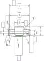
图4描绘了根据本发明的实施例的带扣组件的侧视图。4 depicts a side view of a buckle assembly according to an embodiment of the present invention.
图5描绘了根据本发明另一实施例的带扣组件的侧视图。5 depicts a side view of a buckle assembly according to another embodiment of the present invention.
图6描绘了根据本发明的实施例的带扣的俯视图。6 depicts a top view of a buckle according to an embodiment of the present invention.
图7描绘了根据本发明实施例的带扣连接器的俯视图。7 depicts a top view of a buckle connector according to an embodiment of the present invention.
图8描绘了根据本发明实施例的带扣连接器的侧视图。8 depicts a side view of a buckle connector according to an embodiment of the present invention.
图9描绘了根据本发明的实施例的具有自紧滑动构件的止血带带扣的俯视图。9 depicts a top view of a tourniquet buckle with a self-tightening slide member in accordance with an embodiment of the present invention.
具体实施方式Detailed ways
以下是本发明的各种实施例的描述。The following is a description of various embodiments of the invention.
现在参考图1-3,根据本发明的止血带101包括与基底115接合的束带110。束带110的宽度优选在约1英寸至约3英寸之间,并且更优选地,宽度在约1英寸至约2英寸之间。在示例性实施例中,束带具有约1.5英寸的宽度。Referring now to FIGS. 1-3 , a tourniquet 101 according to the present invention includes a
止血带110的第一端在附接点120处固定地附接,例如缝合,至基底115。然后,束带110穿过止血带手柄125和/或与止血带手柄125接合,并在基底115的第二端处与基底115重新接合。束带110然后从基底115的第二端延伸至少足够的距离,以允许将绑带缠绕在中等大小的成年男性的肢体周围。在一些实施例中,止血带手柄可以以美国专利No.7,776,064中描述的方式附接到基底115,该专利通过引用并入本文。The first end of
根据本发明,根据本发明的止血带的示例性实施例还包括带扣组件130,该带扣组件130包括自紧式,可旋转的带扣135和带扣连接器140。如图1-5和图9所示,在一些实施例中,带扣135包括框架构件137,框架构件137具有与框架构件137接合的自紧滑动构件139。在一些实施例中,自紧滑动构件139包括诸如翻边(cuff)或杆(bar)之类的结构构件,其延伸越过框架构件137的开口并且分别与框架构件137的第一和第二相对侧137A和137B形成榫槽型(tongue and groove type)接合。如图1-5所示,束带110在自紧滑动构件139上成环,从而通过简单地拉动束带110的自由端,自紧滑动构件139沿着框架构件137滑动直到束带110被夹在自紧滑动构件139与框架构件137的侧137a和/或侧137b之间。In accordance with the present invention, exemplary embodiments of tourniquets in accordance with the present invention further include a
如图4-6和9所示,阶梯状矩形带扣135包括阶梯构件138和框架构件137。在示例性实施例中,框架构件137包括矩形的三个侧边,即基底137C和两个侧边137A和137B。阶梯构件138从框架构件137突出并且包括凸起的阶梯边缘138A,两个侧支撑件138B和138C以及两个扩口基部138D和138E。凸起的阶梯边缘138A基本平行于基底137C延伸。侧支撑件138B和138C在大约垂直的拐角处与凸起边缘138A整体形成,并朝向基底137C向后延伸。阶梯构件138的基部138D和138E从两个侧支撑件138B和138C向外延伸,并且与侧边137A和137B一体地形成为大致直角。凸起边缘138A的长度略大于钩构件142的宽度W1并且小于框架构件基底137c的长度。在一些实施例中,带扣135具有圆角矩形角。根据图6,在一些实施例中,带扣135的横截面是圆筒形的。相信横截面形状使阶梯构件138和钩构件142之间的摩擦水平最小化,并且允许个人更容易地将阶梯构件138设置到其在带扣连接器140的月牙形槽中的接合位置。As shown in FIGS. 4-6 and 9 , the stepped
根据本发明的另一方面,带扣连接器140靠近基底115的第一端枢转地附接到基底115。进一步如图7所示,带扣连接器140包括钩构件142和带槽基底构件145。钩构件142包括具有内表面的翻边。钩构件142从带槽基底构件145延伸,该带槽基底构件145限定了带接合孔148。如图7中进一步示出的,带槽基底构件145优选地具有圆形边缘,并且包括钩构件142从其延伸的第一基本竖直边145A和稍微弯曲的第二边145B。According to another aspect of the invention, the
如图2-5所示,带扣连接器140通过形成在束带110的第一端附近的环150连接到基底115,并构造成与带扣135和环150形成摩擦配合。在一些实施例中,束带110包括足够柔韧的材料以产生周向带同时接受机械利益机制。在一些实施例中,束带110由重质聚丙烯织带或尼龙织带制成。在示例性实施例中,环150由与束带110相同的材料构成。除非和直到使用者主动地将它们脱开,否则希望保持带扣连接器140与带扣135接合。还期望带扣135在与带扣连接器140接合时能够调整和/或旋转,以有利于束带110的有针对性的,成角度的收紧。此外,有益的是,带扣135在使用后迅速从带扣连接器140脱离。根据本发明的一个方面,如图4-5所示,阶梯构件138可调整地固定在带扣连接器140的月牙形槽中,并且通过与环150和/或钩构件142的内表面接触而保持在其接合位置。环150充当防止带扣135意外脱离的屏障,以及将带扣连接器140附接到基底115的装置。在阶梯构件138与带扣连接器140接合的情况下,带扣135能够相对于带扣连接器140旋转一定程度。超过一定程度的横向和纵向旋转的旋转被认为是由环150扣住带扣135和/或由钩构件142阻止,该钩构件推靠在束带110的环绕在自紧构件139上的部分上。同样地,带扣连接器140可以实现相对于带扣135的这种旋转。图3示出了止血带的示例性实施例,其中当与带扣连接器140接合时带扣135处于旋转位置。在一些实施例中,当与带扣连接器140接合时,带扣135能够横向旋转多达约45度。在另一个实施例中,当与带扣连接器140接合时,带扣135能够纵向旋转多达约180度。As shown in FIGS. 2-5 , the
如图4-5和7所示,带扣连接器140包括翻遍。钩构件142具有纵长尺寸L1和宽度W1。与本发明的一方面一致,钩构件142具有的宽度W1基本上小于带扣框架基底137C的长度。在一实施例中,W1为137C的长度的一半。因为框架构件135的开口的尺寸大于钩构件142的长度,所以个体在压力下更容易将带扣连接器140连接至带扣135,因为其使复杂的电机运动(motor movement)最小化并且降低了将带扣连接器140连接到带扣135需要的手眼协调度。这些是在弱光,高压力战斗环境中特别重要的考虑因素。As shown in FIGS. 4-5 and 7 , the
如图8所示,钩构件142与带槽基底构件145整体形成。钩构件142大致为J形,并且包括槽142A,支腿142B以及与支腿142B一体形成的端部142。端部142C与142B的轴线偏移大约15度的角度。该偏移的端部用作斜坡并且有助于将阶梯边缘138A插入到钩构件142的槽142A中。As shown in FIG. 8 , the
根据本发明的另一方面,希望最小化例如在患者运动过程中如果止血带被卡住时可能发生的止血带的松动。因此,环150穿过孔眼148并且例如通过缝合固定地附接到基底115,以将带扣连接器140连接到基底115。当阶梯构件138被放置在带扣连接器140的月牙形槽中时,由于在患者运动或战术撤离期间止血带移位,带扣连接器140倾向于绕环150枢转,并且不倾向于绕带扣135枢转,这最大程度地减少了束带110的意外松动的可能性。。According to another aspect of the invention, it is desirable to minimize the loosening of the tourniquet that may occur, for example, if the tourniquet becomes stuck during patient movement. Thus,
以下示例示出了本发明的止血带带扣的示例性实施例。The following examples illustrate exemplary embodiments of tourniquet buckles of the present invention.
示例Example
图1-9中所示类型的止血带具有由金属制成的带扣135和带扣连接器140。在该示例中,带扣135具有大约0.187”的圆筒直径D1。带扣135具有阶梯构件138和框架构件137。框架构件137包括圆角矩形的三个侧边,其基本长度137C测量为大约1.5”(不包括圆角),延伸长度S(包括邻接的圆角)测量为大约为2.0”。侧边137A和137B每个包括一个圆角的侧度约为0.937”,并且具有不包括约为0.688”侧度的圆角的截短宽度T。阶梯构件138的总长度U大约等于框架延伸的基本长度S或大约2.0”。凸起边缘138A在带扣框架中居中,使得凸起边缘138A的中心大约为0.750”或距框架基底137C大约一半。凸起的阶梯边缘138A的长度(不包括其周围的圆角)约为0.760”,而包括圆角的延伸长度V测量约为1.258”。阶梯构件138的深度与侧边138B和138C的长度大约相等,并且包括圆角在内测量大约为0.654”。扩口阶梯基部138D和138E包括圆角在内各自具有大约0.619”的长度。Tourniquets of the type shown in FIGS. 1-9 have a
在该示例中,带扣连接器140具有钩构件142和带槽杆148。如图7所示,钩构件142具有大约0.750”的宽度W1。带槽杆的竖直长度L2(不包括其圆形边缘)约为1.640”,宽度W2(不包括其圆形边缘)约为0.365”。带槽杆148具有大致圆形的矩形孔,该孔在杆148中近似居中,并且具有大约1.562”的长度L3和大约0.125”的宽度W3。In this example, the
如图8所示,钩构件142是与带槽基底构件145整体形成的大体J形结构。带槽基底构件145具有宽度W4.64”。钩构件142具有直径D2约为.336”的大致半球形的槽,并且具有长度测量为约.389”的支腿142B。与支腿142B整体形成的是端部142C,其长度约为0.163”,并且与支腿142B的轴线偏移的角度高达约15度。As shown in FIG. 8 ,
虽然已经通过特定实施例和替代例示出和描述了本发明,但是应当理解,在不脱离本发明的精神和范围的情况下,可以做出许多改变和修改。因此,应该理解,除了根据所附权利要求及其等同物之外,本发明不以任何方式受到限制。Although the present invention has been shown and described in terms of specific embodiments and alternatives, it should be understood that various changes and modifications can be made without departing from the spirit and scope of the invention. Therefore, it should be understood that the present invention is not to be limited in any way except in light of the appended claims and their equivalents.
Claims (20)
Translated fromChineseApplications Claiming Priority (3)
| Application Number | Priority Date | Filing Date | Title |
|---|---|---|---|
| US201762475854P | 2017-03-23 | 2017-03-23 | |
| US62/475,854 | 2017-03-23 | ||
| PCT/US2018/024126WO2018175953A1 (en) | 2017-03-23 | 2018-03-23 | Tourniquet with rotatable buckle assembly |
Publications (2)
| Publication Number | Publication Date |
|---|---|
| CN111432681Atrue CN111432681A (en) | 2020-07-17 |
| CN111432681B CN111432681B (en) | 2023-04-07 |
Family
ID=63586580
Family Applications (1)
| Application Number | Title | Priority Date | Filing Date |
|---|---|---|---|
| CN201880033748.8AActiveCN111432681B (en) | 2017-03-23 | 2018-03-23 | Tourniquet with rotatable buckle assembly |
Country Status (9)
| Country | Link |
|---|---|
| US (2) | US11826053B2 (en) |
| EP (1) | EP3606372B1 (en) |
| JP (1) | JP7296935B2 (en) |
| CN (1) | CN111432681B (en) |
| AU (2) | AU2018240480B2 (en) |
| CA (1) | CA3057624A1 (en) |
| LT (1) | LT3606372T (en) |
| PL (1) | PL3606372T3 (en) |
| WO (1) | WO2018175953A1 (en) |
Families Citing this family (7)
| Publication number | Priority date | Publication date | Assignee | Title |
|---|---|---|---|---|
| US11197520B2 (en)* | 2017-02-10 | 2021-12-14 | Kuraray Fastening Co., Ltd. | Fixing belt, fixing method, and fixing belt member |
| USD860858S1 (en)* | 2018-01-08 | 2019-09-24 | Edge-Works Manufacturing Company | Belt buckle |
| JP7165275B2 (en)* | 2019-05-08 | 2022-11-02 | タクティカル メディカル ソリューションズ, エルエルシー | windlass tourniquet |
| CA3100531A1 (en)* | 2019-11-26 | 2021-05-26 | Acme United Corporation | Medical tourniquet |
| US11779345B2 (en) | 2020-05-07 | 2023-10-10 | Shane Michael Wagner | Tourniquet |
| US12357320B2 (en) | 2021-09-30 | 2025-07-15 | Benjamin Latham Griffith | Tourniquet |
| USD1085414S1 (en)* | 2025-04-16 | 2025-07-22 | Jiale Yu | Self-locking tourniquet |
Citations (9)
| Publication number | Priority date | Publication date | Assignee | Title |
|---|---|---|---|---|
| JPH0751275A (en)* | 1993-08-17 | 1995-02-28 | Sumitomo Rubber Ind Ltd | Pressure stanching belt |
| CN2330310Y (en)* | 1998-07-28 | 1999-07-28 | 朱宏珂 | Elastic tourniquet hemostat |
| US20050113866A1 (en)* | 2003-10-10 | 2005-05-26 | Heinz Thomas J. | Mechanical advantage tourniquet |
| US20050240217A1 (en)* | 2004-04-21 | 2005-10-27 | Johnson Jennifer | Tourniquet article |
| US20060185131A1 (en)* | 2005-02-22 | 2006-08-24 | Anderson Jeffrey D | Buckle assembly |
| US20120071917A1 (en)* | 2010-09-14 | 2012-03-22 | PSR Group, Inc. | Self-Locking Tourniquet and Automated Timer |
| CN102883667A (en)* | 2009-12-09 | 2013-01-16 | 战术医疗方案公司 | Tourniquet |
| JP2013056128A (en)* | 2011-09-09 | 2013-03-28 | Momijiya Hozai Kk | Strap connector, strap mounting device and buckle using the same, and method of assembling the strap mounting device |
| CN104720863A (en)* | 2015-04-08 | 2015-06-24 | 中国人民解放军第三军医大学第二附属医院 | Intelligent multifunctional tourniquet used in field |
Family Cites Families (76)
| Publication number | Priority date | Publication date | Assignee | Title |
|---|---|---|---|---|
| USRE21948E (en)* | 1941-11-18 | Buckle | ||
| US611794A (en) | 1898-10-04 | Harry s | ||
| US462547A (en) | 1891-11-03 | Suspender buckle | ||
| US496630A (en) | 1893-05-02 | Garment-supporter | ||
| US818292A (en) | 1905-04-03 | 1906-04-17 | William W Reid | Buckle-hook. |
| US1416417A (en) | 1920-07-21 | 1922-05-16 | James B Robinson | Buckle and band hook |
| US1419592A (en) | 1921-10-05 | 1922-06-13 | Henry G Sturges | Four-way-strap buckle |
| US1708985A (en) | 1928-01-28 | 1929-04-16 | Wadsworth Watch Case Co | Buckle and the method of making it |
| US1855482A (en) | 1928-11-13 | 1932-04-26 | Bassick Co | Knob for drawers or the like |
| US1887096A (en) | 1932-02-17 | 1932-11-08 | American Buckle Company | Slide buckle |
| US2084412A (en) | 1932-03-15 | 1937-06-22 | Theodore H Low | Buckle |
| US2037558A (en)* | 1932-12-10 | 1936-04-14 | Eastern Tool & Mfg Co | Slide |
| US2250977A (en) | 1939-09-01 | 1941-07-29 | Ralph M Walker | Weatherproof box for electric circuit breakers and other electrical devices |
| US2387428A (en) | 1943-07-12 | 1945-10-23 | Norman W Brothers | Tourniquet |
| GB572460A (en) | 1943-12-24 | 1945-10-09 | John Raymond Cuthbert Quilter | Improvements in and relating to parachute harness |
| US2403712A (en)* | 1944-10-26 | 1946-07-09 | Eastern Tool And Mfg Company | Slide loop |
| US2480430A (en) | 1945-07-12 | 1949-08-30 | Walters John Nugent | Finger-weight artery compressor |
| US2422459A (en) | 1945-11-13 | 1947-06-17 | Eastern Tool & Mfg Co | Slide loop buckle |
| GB674631A (en) | 1948-12-16 | 1952-06-25 | Berger Brothers Co | Improvements in or relating to buckles for clamping straps, tapes and the like |
| US3404436A (en) | 1966-05-06 | 1968-10-08 | Arthur W. Mcmurray | Buckle and strap combination |
| USD260074S (en) | 1979-09-26 | 1981-08-04 | Ray Lewis & Son, Inc. | Combined adjustable curtain rod holder and rod |
| DE3314099A1 (en) | 1983-04-19 | 1984-10-25 | Prämeta Präzisionsmetall- u. Kunststofferzeugnisse G. Baumann & Co, 5000 Köln | CABINET WITH A BELT BUCKLE AND A STRAW STRAP |
| JPS59232531A (en) | 1983-06-15 | 1984-12-27 | 松下電工株式会社 | Hemomanometer |
| DE3327528C2 (en) | 1983-07-30 | 1986-09-25 | Blasius 7455 Jungingen Speidel | Jam tape for congesting blood |
| US4794656A (en) | 1984-08-20 | 1989-01-03 | Henley Jr Albert F | Emergency backboard |
| US4610056A (en) | 1984-11-05 | 1986-09-09 | Emmert Raymond L | Quick connect and release buckle |
| US4551889A (en) | 1984-11-21 | 1985-11-12 | Allied Corporation | Low friction self-locking adjust tongue |
| US4608735A (en) | 1985-08-15 | 1986-09-02 | Nippon Notion Kogyo Co., Ltd. | Sliding bar buckle |
| GB2179392B (en) | 1985-08-21 | 1989-08-23 | Nippon Notion Kogyo | Sliding bar buckle |
| US4778033A (en) | 1987-10-28 | 1988-10-18 | Edwin Gonzalez | Rescue device |
| JPH0711618Y2 (en)* | 1990-01-22 | 1995-03-22 | 道雄 伊藤 | Buckle |
| USD324328S (en) | 1991-02-22 | 1992-03-03 | Zenith Products Corporation | Support rod |
| US5607448A (en) | 1995-05-10 | 1997-03-04 | Daniel A. Stahl | Rolling tourniquet |
| USD385178S (en) | 1996-05-06 | 1997-10-21 | Poulin Robert J | Curtain rod |
| US6540707B1 (en) | 1997-03-24 | 2003-04-01 | Izex Technologies, Inc. | Orthoses |
| US6132383A (en) | 1998-03-20 | 2000-10-17 | Hypertension Diagnostics, Inc. | Apparatus for holding and positioning an arterial pulse pressure sensor |
| US5993362A (en) | 1998-06-03 | 1999-11-30 | Ghobadi; Arthur Soroush | Martial arts conditioning device |
| US6298521B1 (en) | 1999-10-18 | 2001-10-09 | Gary Butterfield | Door knob sanitizing device |
| US6602214B2 (en) | 1999-10-19 | 2003-08-05 | Bio Cybernetics International | Orthotic trauma device |
| US6899720B1 (en) | 2000-12-14 | 2005-05-31 | Diane C. McMillan | Tourniquet |
| CN2467055Y (en) | 2001-02-26 | 2001-12-26 | 刘乃俊 | Tourniquet buckle |
| US6884254B2 (en) | 2001-08-03 | 2005-04-26 | Shan L. Brooks | Tourniquet system |
| US6746470B2 (en) | 2002-01-18 | 2004-06-08 | Mcewen James Allen | Emergency and military tourniquet for pre-hospital use |
| US20050049630A1 (en) | 2002-04-18 | 2005-03-03 | Robert Ambach | Tourniquet device for single-handed operation |
| US7058550B2 (en) | 2003-06-25 | 2006-06-06 | Lockheed Martin Corporation | Selectively resampling particle filter |
| WO2005090297A1 (en) | 2004-03-19 | 2005-09-29 | Biotie Therapies Corporation | Sulphonamide derivatives |
| WO2005090207A1 (en) | 2004-03-24 | 2005-09-29 | Leslie John Spicer | Adjustable lifting handles |
| USD516901S1 (en) | 2004-04-07 | 2006-03-14 | Karen Murray | Extensible hanger |
| WO2006071251A2 (en) | 2004-04-07 | 2006-07-06 | Tiax Llc | Tourniquet and method of using same |
| DE05757785T1 (en) | 2004-06-08 | 2007-10-11 | Phil Durango LLC, Golden | STUMP CUFF AND APPLICATION METHOD |
| US20060095072A1 (en) | 2004-10-29 | 2006-05-04 | Sonos Models, Inc. | Field circulatory constriction device |
| USD545663S1 (en) | 2004-11-09 | 2007-07-03 | Sugatsune Kogyo Co., Ltd. | Handle for door fittings |
| USD527981S1 (en) | 2004-11-09 | 2006-09-12 | Sugatsune Kogyo Co., Ltd. | Knob for furniture |
| US20060218761A1 (en) | 2005-04-04 | 2006-10-05 | Joseph Anscher | Buckle with strap securing bar |
| US8348970B2 (en) | 2005-06-20 | 2013-01-08 | Mark Donald | Military emergency tourniquet |
| US20080221612A1 (en) | 2006-11-15 | 2008-09-11 | Rose Keith J | Internal tourniquet system |
| MX339681B (en)* | 2006-11-15 | 2016-06-03 | Salang Llc | Tourniquet system. |
| US7752722B2 (en) | 2006-12-23 | 2010-07-13 | Skedco, Inc. | Adjustable length litter strap assembly |
| US20080183207A1 (en) | 2007-01-25 | 2008-07-31 | Horne John N | Tourniquet |
| US7685099B2 (en) | 2007-06-28 | 2010-03-23 | Microsoft Corporation | Forecasting time-independent search queries |
| US20090024159A1 (en) | 2007-07-21 | 2009-01-22 | Joseph Patrick Nee | Tourniquet with wooden windlace |
| EP2185079B1 (en) | 2007-08-24 | 2021-10-06 | Keith J. Rose | Tourniquet system |
| US7892253B2 (en) | 2007-08-28 | 2011-02-22 | Phil Durango, Llc | Tourniquet and method of use |
| US20090151132A1 (en) | 2007-12-12 | 2009-06-18 | Rotunno Jr Gerald | Buckle and buckle-strap assembly |
| USD592484S1 (en) | 2008-03-27 | 2009-05-19 | Newell Operating Company | Knob |
| US20100234877A1 (en) | 2008-04-16 | 2010-09-16 | David Pienkowski | Electromechanical tourniquet for battlefield application |
| US8343182B2 (en) | 2008-09-04 | 2013-01-01 | Kirkham Jeffrey B | Tourniquet assembly |
| US8065781B2 (en) | 2008-12-01 | 2011-11-29 | Huntex Corporation | Adjustable tourniquet |
| CN201375542Y (en) | 2009-03-06 | 2010-01-06 | 天津蓝蛇医疗器械有限公司 | Clamping buckle type tourniquet |
| CN201441415U (en) | 2009-08-14 | 2010-04-28 | 王绪友 | Buckle type tourniquet |
| US8776323B2 (en)* | 2010-10-29 | 2014-07-15 | Richard E. McLennan | Cargo strap |
| CN202505426U (en) | 2012-03-20 | 2012-10-31 | 刘传敏 | Modified buckle type arteriola and vein tourniquet |
| CN202497191U (en) | 2012-03-22 | 2012-10-24 | 魏超峰 | Timing buckle tourniquet |
| US20160367262A1 (en)* | 2015-06-18 | 2016-12-22 | Samuel E. Burke | Tourniquet and Windlass Assembly and Method |
| CN205102076U (en) | 2015-10-16 | 2016-03-23 | 郑州创亿达照明有限公司 | Quick connect buckle |
| US10718406B2 (en)* | 2017-11-17 | 2020-07-21 | Pure Safety Group, Inc. | Ratcheting strap adjuster |
- 2018
- 2018-03-23USUS16/496,611patent/US11826053B2/enactiveActive
- 2018-03-23WOPCT/US2018/024126patent/WO2018175953A1/ennot_activeCeased
- 2018-03-23JPJP2020501433Apatent/JP7296935B2/enactiveActive
- 2018-03-23CACA3057624Apatent/CA3057624A1/enactivePending
- 2018-03-23PLPL18771970.3Tpatent/PL3606372T3/enunknown
- 2018-03-23LTLTEPPCT/US2018/024126Tpatent/LT3606372T/enunknown
- 2018-03-23EPEP18771970.3Apatent/EP3606372B1/enactiveActive
- 2018-03-23CNCN201880033748.8Apatent/CN111432681B/enactiveActive
- 2018-03-23AUAU2018240480Apatent/AU2018240480B2/enactiveActive
- 2019
- 2019-09-23USUS16/579,175patent/US11937829B2/enactiveActive
- 2024
- 2024-02-16AUAU2024201034Apatent/AU2024201034A1/enactivePending
Patent Citations (9)
| Publication number | Priority date | Publication date | Assignee | Title |
|---|---|---|---|---|
| JPH0751275A (en)* | 1993-08-17 | 1995-02-28 | Sumitomo Rubber Ind Ltd | Pressure stanching belt |
| CN2330310Y (en)* | 1998-07-28 | 1999-07-28 | 朱宏珂 | Elastic tourniquet hemostat |
| US20050113866A1 (en)* | 2003-10-10 | 2005-05-26 | Heinz Thomas J. | Mechanical advantage tourniquet |
| US20050240217A1 (en)* | 2004-04-21 | 2005-10-27 | Johnson Jennifer | Tourniquet article |
| US20060185131A1 (en)* | 2005-02-22 | 2006-08-24 | Anderson Jeffrey D | Buckle assembly |
| CN102883667A (en)* | 2009-12-09 | 2013-01-16 | 战术医疗方案公司 | Tourniquet |
| US20120071917A1 (en)* | 2010-09-14 | 2012-03-22 | PSR Group, Inc. | Self-Locking Tourniquet and Automated Timer |
| JP2013056128A (en)* | 2011-09-09 | 2013-03-28 | Momijiya Hozai Kk | Strap connector, strap mounting device and buckle using the same, and method of assembling the strap mounting device |
| CN104720863A (en)* | 2015-04-08 | 2015-06-24 | 中国人民解放军第三军医大学第二附属医院 | Intelligent multifunctional tourniquet used in field |
Also Published As
| Publication number | Publication date |
|---|---|
| US20200015828A1 (en) | 2020-01-16 |
| JP2020512913A (en) | 2020-04-30 |
| CA3057624A1 (en) | 2018-09-27 |
| US20200288820A1 (en) | 2020-09-17 |
| EP3606372A1 (en) | 2020-02-12 |
| US11826053B2 (en) | 2023-11-28 |
| PL3606372T3 (en) | 2025-01-07 |
| LT3606372T (en) | 2024-09-10 |
| AU2024201034A1 (en) | 2024-03-07 |
| JP7296935B2 (en) | 2023-06-23 |
| AU2018240480B2 (en) | 2024-03-28 |
| EP3606372B1 (en) | 2024-05-29 |
| WO2018175953A1 (en) | 2018-09-27 |
| BR112019019878A2 (en) | 2020-04-22 |
| AU2018240480A1 (en) | 2019-10-24 |
| CN111432681B (en) | 2023-04-07 |
| US11937829B2 (en) | 2024-03-26 |
| EP3606372A4 (en) | 2020-12-30 |
Similar Documents
| Publication | Publication Date | Title |
|---|---|---|
| US20230057363A1 (en) | Tourniquet and connection assembly therefor | |
| CN111432681B (en) | Tourniquet with rotatable buckle assembly | |
| EP3048997B1 (en) | A mechanical tourniquet apparatus and method of making such a tourniquet | |
| US7981135B2 (en) | Garment with affixed tourniquet | |
| US20180353189A1 (en) | Tourniquet | |
| US12042154B2 (en) | Windlass tourniquet | |
| US11504135B2 (en) | Mechanical tourniquet apparatus and method of use | |
| BR112019019878B1 (en) | TOURNIQUET WITH SWIVEL BUCKLE ASSEMBLY |
Legal Events
| Date | Code | Title | Description |
|---|---|---|---|
| PB01 | Publication | ||
| PB01 | Publication | ||
| SE01 | Entry into force of request for substantive examination | ||
| SE01 | Entry into force of request for substantive examination | ||
| GR01 | Patent grant | ||
| GR01 | Patent grant |