CN111432301A - A wearable audio device based on piezoresistive touch - Google Patents
A wearable audio device based on piezoresistive touchDownload PDFInfo
- Publication number
- CN111432301A CN111432301ACN202010190014.XACN202010190014ACN111432301ACN 111432301 ACN111432301 ACN 111432301ACN 202010190014 ACN202010190014 ACN 202010190014ACN 111432301 ACN111432301 ACN 111432301A
- Authority
- CN
- China
- Prior art keywords
- touch
- flexible
- wearable audio
- pressure sensor
- audio device
- Prior art date
- Legal status (The legal status is an assumption and is not a legal conclusion. Google has not performed a legal analysis and makes no representation as to the accuracy of the status listed.)
- Pending
Links
Images


Classifications
- H—ELECTRICITY
- H04—ELECTRIC COMMUNICATION TECHNIQUE
- H04R—LOUDSPEAKERS, MICROPHONES, GRAMOPHONE PICK-UPS OR LIKE ACOUSTIC ELECTROMECHANICAL TRANSDUCERS; DEAF-AID SETS; PUBLIC ADDRESS SYSTEMS
- H04R1/00—Details of transducers, loudspeakers or microphones
- H04R1/10—Earpieces; Attachments therefor ; Earphones; Monophonic headphones
Landscapes
- Physics & Mathematics (AREA)
- Engineering & Computer Science (AREA)
- Acoustics & Sound (AREA)
- Signal Processing (AREA)
- Push-Button Switches (AREA)
Abstract
Translated fromChinese
Description
Translated fromChinese技术领域technical field
本发明属于智能音频设备领域,具体涉及一种基于压阻式触控的佩戴式音频设备。The invention belongs to the field of intelligent audio equipment, and particularly relates to a wearable audio equipment based on piezoresistive touch.
背景技术Background technique
随着电子产品的普及,佩戴式音频设备越来越普遍现身于人们的生活当中。从最初的有线音频设备,到流行的蓝牙无线音频设备,以及现在刚出现的TWS即真无线立体声音频设备。无线音频设备摆脱了线材的束缚,携带更加方便,体验更加自由惬意。目前主流的无线音频设备的操作方式主要有三种:触控、按键和语音控制。基于触控式操作的佩戴式音频设备因外观设计新颖美观,能防水防汗,触控操作部件不占产品空间而大受消费者欢迎。触控操作主要基于触摸芯片实现,目前基于触摸芯片的触控式操作存在在灵敏度和误触之间难以平衡、功耗高以及易受外部干扰而导致的误动作等问题。按键式操作因需要开孔存在不防水的问题,同时戴在耳朵上按键操作会形成有噪音并挤压耳洞,让耳朵很不舒服。语音控制在嘈杂环境以及不适合发音环境下难以实现操作目的。With the popularity of electronic products, wearable audio devices are more and more common in people's lives. From the original wired audio equipment, to the popular Bluetooth wireless audio equipment, and now TWS, the true wireless stereo audio equipment, has just appeared. Wireless audio equipment is free from the shackles of wires, making it more convenient to carry and experience a more free and comfortable experience. At present, there are three main operation modes of mainstream wireless audio devices: touch, key and voice control. Wearable audio devices based on touch operation are very popular among consumers because of their novel and beautiful appearance design, waterproof and sweatproof, and touch operation components that do not occupy product space. The touch operation is mainly implemented based on the touch chip. At present, the touch operation based on the touch chip has problems such as difficulty in balancing sensitivity and false touch, high power consumption, and misoperation caused by external interference. The button-type operation is not waterproof due to the need to open the hole. At the same time, the button operation on the ear will cause noise and squeeze the ear hole, making the ear very uncomfortable. Voice control is difficult to achieve in noisy environments and environments that are not suitable for pronunciation.
发明内容SUMMARY OF THE INVENTION
本发明的目的是克服现有技术中佩戴式音频设备存在的灵敏度和误触之间难以平衡、功耗高以及易受外部干扰而导致的误动作等缺陷,提供一种本发明的触控操作方式既保留了戴式音频设备因设计新颖美观,触控敏感度高,体积小,低功耗,低成本,能防水防汗的基于压阻式触控的佩戴式音频设备。The purpose of the present invention is to overcome the defects of the wearable audio device in the prior art, such as difficulty in balancing sensitivity and false touch, high power consumption, and misoperation caused by external interference, and provide a touch operation of the present invention. The method not only retains the wearable audio device based on piezoresistive touch because of its novel and beautiful design, high touch sensitivity, small size, low power consumption, low cost, and waterproof and sweat-proof.
本发明解决其技术问题所采用的技术方案是:一种基于压阻式触控的佩戴式音频设备,其特征在于:包括设置在佩戴式音频设备外壳上的感应区、安装在所述感应区对应的外壳内侧的柔性压力传感器;所述感应区对应的外壳厚度小于所述外壳的其他部位;所述柔性压力传感器包括最下层采用柔性材料做成的柔性基底;从下到上依次设置在柔性基底上的电极层和敏感层、覆盖于敏感层及电极层上表面的保护层。The technical solution adopted by the present invention to solve the technical problem is: a wearable audio device based on piezoresistive touch, which is characterized in that it includes a sensing area arranged on the shell of the wearable audio device, and a sensor area installed in the sensing area. The corresponding flexible pressure sensor on the inner side of the casing; the thickness of the casing corresponding to the sensing area is smaller than that of other parts of the casing; the flexible pressure sensor includes a flexible substrate whose bottom layer is made of flexible materials; The electrode layer and the sensitive layer on the substrate, and the protective layer covering the upper surface of the sensitive layer and the electrode layer.
进一步地,所述外壳内设置有信号处理电路模块、控制器及触控反馈部件;所述柔性压力传感器与所述信号处理电路模块电连接;所述信号处理电路模块与所述控制器通讯连接,所述触控反馈部件与所述控制器通讯连接;Further, a signal processing circuit module, a controller and a touch feedback component are arranged in the casing; the flexible pressure sensor is electrically connected to the signal processing circuit module; the signal processing circuit module is communicatively connected to the controller , the touch feedback component is connected in communication with the controller;
所述信号处理电路模块包括信号采集转换电路和模数转换器,所述采集转换电路采集所述柔性压力传感器发出的压力信号,将压力信号转换成模拟电信号传输给所述模数转换器,所述模数转换器将模拟电信号转化成数字信号输出给所述控制器;The signal processing circuit module includes a signal acquisition and conversion circuit and an analog-to-digital converter, the acquisition and conversion circuit collects the pressure signal sent by the flexible pressure sensor, converts the pressure signal into an analog electrical signal and transmits it to the analog-to-digital converter, The analog-to-digital converter converts the analog electrical signal into a digital signal and outputs it to the controller;
所述控制器,用于将接收到的数字信号与存储的阈值进行比较,发出控制指令;The controller is used to compare the received digital signal with the stored threshold, and issue a control command;
所述触控反馈部件,用于接收控制器的指令并反馈触感。The touch feedback component is used for receiving the instruction of the controller and feeding back the touch feeling.
进一步地,所述感应区为外壳上的一处凹陷,所述感应区对应的外壳材料为薄塑料软壳。Further, the sensing area is a depression on the casing, and the casing material corresponding to the sensing area is a thin plastic soft casing.
进一步地,触控反馈部件为微型马达,通过震动来反馈触感。Further, the touch feedback component is a micro motor, which feedbacks the tactile sensation through vibration.
进一步地,所述柔性基底采用的柔性材料为乙烯-醋酸乙烯共聚物、聚乙烯醇、聚二甲基硅氧烷、聚对苯二甲酸乙二酯、聚甲基丙烯酸甲酯、聚酰亚胺、热塑性聚氨酯弹性体、聚氨酯和聚乙烯中的一种材料或多种材料的混合物。Further, the flexible materials used for the flexible substrate are ethylene-vinyl acetate copolymer, polyvinyl alcohol, polydimethylsiloxane, polyethylene terephthalate, polymethyl methacrylate, polyimide One or a mixture of amines, thermoplastic polyurethane elastomers, polyurethane and polyethylene.
进一步地,所述电极层为采用微纳米导电材料制成的至少含有2根电极线的阵列电极,所述电极层通过无胶柔性印刷电路板设置于所述柔性基底的表面。Further, the electrode layer is an array electrode made of a micro-nano conductive material and containing at least two electrode lines, and the electrode layer is disposed on the surface of the flexible substrate through an adhesive-free flexible printed circuit board.
进一步地,所述微纳米导电材料为银、银纳米线、ITO、碳纳米材料、PEDOT:PSS中的一种材料或多种材料的混合物。Further, the micro-nano conductive material is one material or a mixture of multiple materials among silver, silver nanowires, ITO, carbon nanomaterials, and PEDOT:PSS.
进一步地,敏感层是在电极层上利用静电纺丝技术制备厚度为100纳米-100微米的多孔碳纳米纤维薄膜。Further, the sensitive layer is a porous carbon nanofiber film with a thickness of 100 nanometers to 100 micrometers prepared on the electrode layer by electrospinning technology.
更进一步地,所述保护层是利用超声雾化喷涂技术在所述敏感层表面通过原位聚合形成厚度在10nm-10um之间的超薄柔性封装保护膜。Further, the protective layer is an ultra-thin flexible packaging protective film with a thickness of between 10 nm and 10 um formed by in-situ polymerization on the surface of the sensitive layer by using ultrasonic atomization spraying technology.
本发明的一种基于压阻式触控的佩戴式音频设备的有益效果是:The beneficial effects of a wearable audio device based on piezoresistive touch of the present invention are:
1、本发明利用柔性压力传感器的轻薄柔韧,极大提高了触控敏感度,能有效感知触摸力度的大小,达到不同触摸力度实现不同的触摸功能的目的,同时,体积小,结构简单,长期稳定性好,功耗低,能有效的节省电量,为佩戴式音频设备增加使用时间。1. The present invention utilizes the lightness, thinness and flexibility of the flexible pressure sensor, which greatly improves the touch sensitivity, can effectively sense the size of the touch force, and achieve the purpose of realizing different touch functions with different touch forces. Good stability, low power consumption, can effectively save power, and increase the use time for wearable audio equipment.
2、本发明的佩戴式音频设备外壳上设置有内凹型且硬度较小的感应区,其将感应区设计为外壳的一部分,即保证了柔性压力传感器对压力的感知,又起到防水防汗的功能。2. The casing of the wearable audio device of the present invention is provided with a concave and less rigid sensing area, and the sensing area is designed as a part of the casing, which not only ensures the pressure perception of the flexible pressure sensor, but also plays the role of waterproof and sweatproof. function.
附图说明Description of drawings
下面结合附图和具体实施方式对本发明作进一步详细的说明。The present invention will be described in further detail below with reference to the accompanying drawings and specific embodiments.
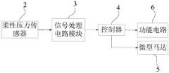
图1是本发明实施例的结构图;1 is a structural diagram of an embodiment of the present invention;
图2是本发明实施例的信号传输流程图;Fig. 2 is the signal transmission flow chart of the embodiment of the present invention;
图3是本发明实施例的柔性压力传感器与感应区安装图;3 is an installation diagram of a flexible pressure sensor and a sensing area according to an embodiment of the present invention;
图4是本发明实施例的信号采集转换电路图;4 is a circuit diagram of a signal acquisition and conversion circuit according to an embodiment of the present invention;
图5是本发明实施例的模数转换器电路图;5 is a circuit diagram of an analog-to-digital converter according to an embodiment of the present invention;
图6是本发明实施例的控制器电路图;Fig. 6 is the controller circuit diagram of the embodiment of the present invention;
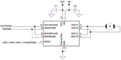
图7是本发明实施例的微型马达控制电路图。FIG. 7 is a diagram of a micromotor control circuit according to an embodiment of the present invention.
图中:1、感应区,2、柔性压力传感器,3、信号处理电路模块,4、控制器,5、微型马达,6、功能电路,C1、柔性基底,C2、电极层,C3、敏感层,C4、保护层。In the figure: 1. Induction area, 2. Flexible pressure sensor, 3. Signal processing circuit module, 4. Controller, 5. Micro motor, 6. Functional circuit, C1, flexible substrate, C2, electrode layer, C3, sensitive layer , C4, protective layer.
具体实施方式Detailed ways
现在结合附图对本发明作进一步详细的说明。这些附图均为简化的示意图,仅以示意方式说明本发明的基本结构,因此其仅显示与本发明有关的构成。The present invention will now be described in further detail with reference to the accompanying drawings. These drawings are all simplified schematic diagrams, and only illustrate the basic structure of the present invention in a schematic manner, so they only show the structures related to the present invention.
如图1到图7所示的本发明的一种基于压阻式触控的佩戴式音频设备的具体实施例,佩戴式音频设备可以是耳机、音响等,本发明实施例以蓝牙耳机为例,包括设置在佩戴式音频设备外壳上的感应区1、安装在所述感应区1对应的外壳内侧的柔性压力传感器2;所述感应区1对应的外壳厚度小于所述外壳的其他部位;所述柔性压力传感器2包括最下层采用柔性材料做成的柔性基底C1;从下到上依次设置在柔性基底C1上的电极层C2和敏感层C3、覆盖于敏感层C3及电极层C2上表面的保护层C4。外壳内还设置有信号处理电路模块3、控制器4及触控反馈部件;柔性压力传感器2与信号处理电路模块3电连接;信号处理电路模块3与控制器4通讯连接,触控反馈部件与控制器4通讯连接;信号处理电路模块3包括信号采集转换电路和模数转换器,采集转换电路采集柔性压力传感器2发出的压力信号,将压力信号转换成模拟电信号传输给模数转换器,模数转换器将模拟电信号转化成数字信号输出给控制器4;控制器4,用于将接收到的数字信号与存储的阈值进行比较,发出控制指令;触控反馈部件,用于接收控制器4的指令并反馈触感。As shown in FIG. 1 to FIG. 7 , a specific embodiment of a wearable audio device based on piezoresistive touch of the present invention is shown in FIG. 1 . The wearable audio device may be an earphone, a stereo, etc. The embodiment of the present invention takes a Bluetooth earphone as an example. , including a
本发明实施例中感应区1是佩戴式音频设备外壳上的一处凹陷,柔性压力传感器2粘贴在感应区1对应的外壳内侧,感应区1对应的外壳材料为薄塑料软壳,薄塑料软壳厚度为0.05mm-1.5mm,柔性压力传感器2与感应区1所对应的外壳更易贴合,即保证了柔性压力传感器2对压力的感知,又起到防水防汗的功能。In the embodiment of the present invention, the
如图2所示,本实施例中柔性压力传感器2为压阻式超薄柔性压力传感器2,是有带有电极层C2的柔性材料做柔性基底C1,该电极层C2采用微纳米导电材料制成的阵列电极,至少含有2根电极线,电极层C2通过无胶柔性印刷电路板设置于柔性基底C1的表面,在柔性基底C1材料的阵列电极上利用静电纺丝技术制备厚度为100纳米-100微米的多孔碳纳米纤维薄膜作为超薄压阻材料,再利用超声雾化喷涂技术在碳纳米纤维表面通过原位聚合形成厚度在10nm-10um之间的超薄柔性封装保护膜制成的。超声雾化喷涂技术是一种在无接触、无压力、无需印版的条件下能够利用超声波振动能量来实现液体实现连续或间断性的雾化进而实现大面积成膜的技术,该技术其具有喷涂效率高、原材料浪费少、微细雾化颗粒均匀、抗腐蚀性强、精度高、成膜厚度可控性好等优点。As shown in FIG. 2 , the
原位聚合即在位分散聚合,它是使粒子与有机高分子材料共同构建并在一定的条件下就地聚合。本申请中原位聚合法是使通过超声雾化喷涂的有机高分子溶液与多孔碳纳米纤维薄膜材料在加热条件下,在碳纳米纤维表面就地共建聚合形成厚度可控的超薄柔性封装保护膜。In-situ polymerization is in-situ dispersion polymerization, which is to build particles and organic polymer materials together and in-situ polymerization under certain conditions. In this application, the in-situ polymerization method is to co-polymerize the organic polymer solution sprayed by ultrasonic atomization and the porous carbon nanofiber film material on the surface of the carbon nanofiber under heating conditions to form an ultra-thin flexible encapsulation protection with a controllable thickness. membrane.
本实施例中柔性材料为乙烯-醋酸乙烯共聚物、聚乙烯醇、聚二甲基硅氧烷、聚对苯二甲酸乙二酯、聚甲基丙烯酸甲酯、聚酰亚胺、热塑性聚氨酯弹性体、聚氨酯和聚乙烯中的一种材料或多种材料的混合。微纳米导电材料为银、银纳米线、ITO、碳纳米材料、PEDOT:PSS中的一种材料或多种材料的混合。本发明压阻式超薄柔性压力传感器2轻薄柔韧,极大提高了触控敏感度。同时,体积小,结构简单,长期稳定性好,功耗低,能有效的节省电量,为佩戴式音频设备增加使用时间。本发明使用柔性压力传感器2适用曲面,更易贴合曲面既不影响音频设备的灵敏度又能保证音频设备的美观和防水防汗功能。In this embodiment, the flexible material is ethylene-vinyl acetate copolymer, polyvinyl alcohol, polydimethylsiloxane, polyethylene terephthalate, polymethyl methacrylate, polyimide, thermoplastic polyurethane elastic One or a combination of materials, polyurethane and polyethylene. The micro-nano conductive material is one material or a mixture of multiple materials among silver, silver nanowires, ITO, carbon nanomaterials, and PEDOT:PSS. The piezoresistive ultra-thin
本实施例中还设置触控反馈部件,为了让使用者体验感更好,触控反馈部件为微型马达5,当压阻式超薄柔性压力传感器2感知到触控操作时,控制器4发指令给微型马达5,使其通过振动来反馈触感。In this embodiment, a touch feedback component is also provided. In order to make the user experience better, the touch feedback component is a
在音频设备的外壳上进行触控操作时,因为感应区1为外壳上的一个凹陷,所以人手容易定位置操作,基于碳纳米材料的柔性压力传感器2对微弱压力极为敏感,能有效感知触摸力度的大小,且柔性压力传感器2的电极层C2为有多个电极阵列的阵列电极,每个电极阵列都能采集压力数据,从而实现能同时或短时间内采集多点压力数据的技术效果。柔性压力传感器2将感知的压力信号输出给信号处理电路模块3,结合图4到图7,经过采集转换电路转换为模拟信号传输给模数转换器,模数转换器将模拟信号进一步转化成数字信号输出给控制器4,控制器4根据收到的信号判断压力大小和手部按压的时间间隔,发出指令给功能电路6,即可以根据人手触摸的力度和触摸的时间间隔实现不同的触摸功能。比如轻触并上下滑动时实现调节音量大小,中度压力单击播放/暂停/来电接听,中度双击下一曲/来电拒接,中度长按器则关机。本发明实施例中柔性压力传感器2在工作时功耗典型值为1-100uA,其工作电压:2.0-5.5V,不工作时功耗为零,能有效节省电量,为佩戴式音频设备增加使用时间。When a touch operation is performed on the casing of the audio device, because the
应当理解,以上所描述的具体实施例仅用于解释本发明,并不用于限定本发明。由本发明的精神所引伸出的显而易见的变化或变动仍处于本发明的保护范围之中。It should be understood that the specific embodiments described above are only used to explain the present invention, but not to limit the present invention. Obvious changes or modifications derived from the spirit of the present invention are still within the protection scope of the present invention.
Claims (9)
Priority Applications (1)
| Application Number | Priority Date | Filing Date | Title |
|---|---|---|---|
| CN202010190014.XACN111432301A (en) | 2020-03-18 | 2020-03-18 | A wearable audio device based on piezoresistive touch |
Applications Claiming Priority (1)
| Application Number | Priority Date | Filing Date | Title |
|---|---|---|---|
| CN202010190014.XACN111432301A (en) | 2020-03-18 | 2020-03-18 | A wearable audio device based on piezoresistive touch |
Publications (1)
| Publication Number | Publication Date |
|---|---|
| CN111432301Atrue CN111432301A (en) | 2020-07-17 |
Family
ID=71548536
Family Applications (1)
| Application Number | Title | Priority Date | Filing Date |
|---|---|---|---|
| CN202010190014.XAPendingCN111432301A (en) | 2020-03-18 | 2020-03-18 | A wearable audio device based on piezoresistive touch |
Country Status (1)
| Country | Link |
|---|---|
| CN (1) | CN111432301A (en) |
Cited By (2)
| Publication number | Priority date | Publication date | Assignee | Title |
|---|---|---|---|---|
| CN113340480A (en)* | 2021-07-14 | 2021-09-03 | 苏州能斯达电子科技有限公司 | Flexible pressure sensor and preparation method thereof |
| CN114554342A (en)* | 2022-02-10 | 2022-05-27 | 深圳市冠旭电子股份有限公司 | Earphone running state adjusting method and device, electronic equipment and storage medium |
Citations (14)
| Publication number | Priority date | Publication date | Assignee | Title |
|---|---|---|---|---|
| US20070003098A1 (en)* | 2005-06-03 | 2007-01-04 | Rasmus Martenson | Headset |
| WO2009118221A1 (en)* | 2008-03-28 | 2009-10-01 | Oticon A/S | Hearing aid with a manual input terminal comprising a touch sensitive sensor |
| JP3171610U (en)* | 2011-08-26 | 2011-11-10 | 碧芬 林 | Wireless headset device |
| KR20130004892U (en)* | 2012-02-07 | 2013-08-16 | 주식회사 넥시아 디바이스 | Earphone with control pad for audio device |
| CN104395862A (en)* | 2012-06-04 | 2015-03-04 | 索尼电脑娱乐公司 | Flat joystick controller |
| CN206181325U (en)* | 2016-11-04 | 2017-05-17 | 深圳市柔宇科技有限公司 | Earphone wire control device |
| CN206314707U (en)* | 2015-09-30 | 2017-07-11 | 苹果公司 | Earplug |
| CN107708008A (en)* | 2017-09-26 | 2018-02-16 | 出门问问信息科技有限公司 | The control method of wireless headset and wireless headset |
| CN108683975A (en)* | 2018-05-14 | 2018-10-19 | 维沃移动通信有限公司 | an audio device |
| CN109348352A (en)* | 2018-12-21 | 2019-02-15 | 歌尔科技有限公司 | Wearing and touch detection circuit and earphone |
| CN209134600U (en)* | 2018-09-25 | 2019-07-19 | 深圳市汇顶科技股份有限公司 | A kind of earphone |
| CN110618763A (en)* | 2019-08-28 | 2019-12-27 | 华为技术有限公司 | Touch control method and electronic equipment |
| CN210143098U (en)* | 2018-09-21 | 2020-03-13 | 苹果公司 | Electronic equipment and earphone |
| CN211744687U (en)* | 2020-03-18 | 2020-10-23 | 苏州能斯达电子科技有限公司 | A wearable audio device based on piezoresistive touch |
- 2020
- 2020-03-18CNCN202010190014.XApatent/CN111432301A/enactivePending
Patent Citations (14)
| Publication number | Priority date | Publication date | Assignee | Title |
|---|---|---|---|---|
| US20070003098A1 (en)* | 2005-06-03 | 2007-01-04 | Rasmus Martenson | Headset |
| WO2009118221A1 (en)* | 2008-03-28 | 2009-10-01 | Oticon A/S | Hearing aid with a manual input terminal comprising a touch sensitive sensor |
| JP3171610U (en)* | 2011-08-26 | 2011-11-10 | 碧芬 林 | Wireless headset device |
| KR20130004892U (en)* | 2012-02-07 | 2013-08-16 | 주식회사 넥시아 디바이스 | Earphone with control pad for audio device |
| CN104395862A (en)* | 2012-06-04 | 2015-03-04 | 索尼电脑娱乐公司 | Flat joystick controller |
| CN206314707U (en)* | 2015-09-30 | 2017-07-11 | 苹果公司 | Earplug |
| CN206181325U (en)* | 2016-11-04 | 2017-05-17 | 深圳市柔宇科技有限公司 | Earphone wire control device |
| CN107708008A (en)* | 2017-09-26 | 2018-02-16 | 出门问问信息科技有限公司 | The control method of wireless headset and wireless headset |
| CN108683975A (en)* | 2018-05-14 | 2018-10-19 | 维沃移动通信有限公司 | an audio device |
| CN210143098U (en)* | 2018-09-21 | 2020-03-13 | 苹果公司 | Electronic equipment and earphone |
| CN209134600U (en)* | 2018-09-25 | 2019-07-19 | 深圳市汇顶科技股份有限公司 | A kind of earphone |
| CN109348352A (en)* | 2018-12-21 | 2019-02-15 | 歌尔科技有限公司 | Wearing and touch detection circuit and earphone |
| CN110618763A (en)* | 2019-08-28 | 2019-12-27 | 华为技术有限公司 | Touch control method and electronic equipment |
| CN211744687U (en)* | 2020-03-18 | 2020-10-23 | 苏州能斯达电子科技有限公司 | A wearable audio device based on piezoresistive touch |
Cited By (3)
| Publication number | Priority date | Publication date | Assignee | Title |
|---|---|---|---|---|
| CN113340480A (en)* | 2021-07-14 | 2021-09-03 | 苏州能斯达电子科技有限公司 | Flexible pressure sensor and preparation method thereof |
| CN113340480B (en)* | 2021-07-14 | 2023-12-01 | 苏州能斯达电子科技有限公司 | A flexible pressure sensor and its preparation method |
| CN114554342A (en)* | 2022-02-10 | 2022-05-27 | 深圳市冠旭电子股份有限公司 | Earphone running state adjusting method and device, electronic equipment and storage medium |
Similar Documents
| Publication | Publication Date | Title |
|---|---|---|
| CN103900741B (en) | Wearable Intelligent testing fixed system and intelligent shoe | |
| CN102207415A (en) | Conductive-rubber-based flexible array clip pressure sensor and manufacturing method | |
| CN203025677U (en) | Capacitive pressure sensing and converting device | |
| CN110531863B (en) | Flexible touch glove based on super-capacitor sensing principle and preparation method thereof | |
| CN104426412A (en) | Electric-signal output device and electric-signal output method based on skin | |
| CN106095174A (en) | Electronic whiteboard actively pen and touch input system and driving method | |
| CN201048097Y (en) | Keying structure of remote controller | |
| CN111432301A (en) | A wearable audio device based on piezoresistive touch | |
| CN111024272A (en) | A kind of preparation method of capacitive flexible sensor | |
| CN205540679U (en) | Pressure touch devices and have this pressure touch devices's terminal equipment | |
| CN111552381A (en) | Capacitive pressure sensor, preparation method thereof and piano gloves | |
| CN102801835A (en) | Mobile telephone shell provided with pressing input function | |
| CN211744687U (en) | A wearable audio device based on piezoresistive touch | |
| CN205697713U (en) | Flexible wearable device | |
| CN104635562A (en) | Touch sensor, touch sensing system and intelligent robot | |
| CN204695286U (en) | Touch control display apparatus and pressure touch unit | |
| CN210783050U (en) | Intelligent glove | |
| CN203482367U (en) | Earphone | |
| CN103513839A (en) | Touch-and-play input device and operation method | |
| Lin et al. | Dielectrically Modified Polymer and Topologically Optimized Microstructure Enabling In‐Sensor Decoupling for Multifunctional Human–Machine Interactions | |
| CN103780239B (en) | Piezo-electric electret thin film button | |
| CN207283610U (en) | A kind of sound volume control device for intelligent terminal | |
| CN219982223U (en) | A wearable smart glove based on microstructured flexible pressure sensor | |
| CN202772947U (en) | Handset sleeve with pressing input function | |
| CN202008727U (en) | Wireless touchpad remote controller |
Legal Events
| Date | Code | Title | Description |
|---|---|---|---|
| PB01 | Publication | ||
| PB01 | Publication | ||
| SE01 | Entry into force of request for substantive examination | ||
| SE01 | Entry into force of request for substantive examination | ||
| CB03 | Change of inventor or designer information | ||
| CB03 | Change of inventor or designer information | Inventor after:Xiong Zuoping Inventor after:Fan Longfei Inventor after:Wang Yukang Inventor after:Zhou Zhen Inventor before:Xiong Zuoping Inventor before:Fan Longfei Inventor before:Wang Yukang Inventor before:Zhou Zhen Inventor before:Zhang Ting | |
| RJ01 | Rejection of invention patent application after publication | ||
| RJ01 | Rejection of invention patent application after publication | Application publication date:20200717 |