CN111431375A - A terminal welding structure of a lens-integrated motor, a voice coil motor, and a camera device - Google Patents
A terminal welding structure of a lens-integrated motor, a voice coil motor, and a camera deviceDownload PDFInfo
- Publication number
- CN111431375A CN111431375ACN202010364495.1ACN202010364495ACN111431375ACN 111431375 ACN111431375 ACN 111431375ACN 202010364495 ACN202010364495 ACN 202010364495ACN 111431375 ACN111431375 ACN 111431375A
- Authority
- CN
- China
- Prior art keywords
- upper spring
- lens
- winding
- spring
- sub
- Prior art date
- Legal status (The legal status is an assumption and is not a legal conclusion. Google has not performed a legal analysis and makes no representation as to the accuracy of the status listed.)
- Pending
Links
Images


Classifications
- H—ELECTRICITY
- H02—GENERATION; CONVERSION OR DISTRIBUTION OF ELECTRIC POWER
- H02K—DYNAMO-ELECTRIC MACHINES
- H02K41/00—Propulsion systems in which a rigid body is moved along a path due to dynamo-electric interaction between the body and a magnetic field travelling along the path
- H02K41/02—Linear motors; Sectional motors
- H02K41/035—DC motors; Unipolar motors
- H02K41/0352—Unipolar motors
- H02K41/0354—Lorentz force motors, e.g. voice coil motors
- G—PHYSICS
- G03—PHOTOGRAPHY; CINEMATOGRAPHY; ANALOGOUS TECHNIQUES USING WAVES OTHER THAN OPTICAL WAVES; ELECTROGRAPHY; HOLOGRAPHY
- G03B—APPARATUS OR ARRANGEMENTS FOR TAKING PHOTOGRAPHS OR FOR PROJECTING OR VIEWING THEM; APPARATUS OR ARRANGEMENTS EMPLOYING ANALOGOUS TECHNIQUES USING WAVES OTHER THAN OPTICAL WAVES; ACCESSORIES THEREFOR
- G03B13/00—Viewfinders; Focusing aids for cameras; Means for focusing for cameras; Autofocus systems for cameras
- G03B13/32—Means for focusing
- G03B13/34—Power focusing
- G03B13/36—Autofocus systems
- H—ELECTRICITY
- H02—GENERATION; CONVERSION OR DISTRIBUTION OF ELECTRIC POWER
- H02K—DYNAMO-ELECTRIC MACHINES
- H02K15/00—Processes or apparatus specially adapted for manufacturing, assembling, maintaining or repairing of dynamo-electric machines
- H02K15/06—Embedding prefabricated windings in the machines
- H—ELECTRICITY
- H02—GENERATION; CONVERSION OR DISTRIBUTION OF ELECTRIC POWER
- H02K—DYNAMO-ELECTRIC MACHINES
- H02K15/00—Processes or apparatus specially adapted for manufacturing, assembling, maintaining or repairing of dynamo-electric machines
- H02K15/30—Manufacture of winding connections
- H02K15/33—Connecting winding sections; Forming leads; Connecting leads to terminals
- H—ELECTRICITY
- H02—GENERATION; CONVERSION OR DISTRIBUTION OF ELECTRIC POWER
- H02K—DYNAMO-ELECTRIC MACHINES
- H02K3/00—Details of windings
- H02K3/46—Fastening of windings on the stator or rotor structure
Landscapes
- Engineering & Computer Science (AREA)
- Power Engineering (AREA)
- Manufacturing & Machinery (AREA)
- Physics & Mathematics (AREA)
- General Physics & Mathematics (AREA)
- Chemical & Material Sciences (AREA)
- Combustion & Propulsion (AREA)
- Electromagnetism (AREA)
- Lens Barrels (AREA)
Abstract
Description
Translated fromChinese技术领域technical field
本发明涉及照相设备领域,尤其涉及到一种镜头一体马达的端子焊接结构、音圈马达、照相装置。The invention relates to the field of photographic equipment, in particular to a terminal welding structure of a lens-integrated motor, a voice coil motor and a photographing device.
背景技术Background technique
随着科学技术的进步,相机模组的应用越来越广泛,目前,除了相机,手机、电脑等电子设备上都配备了相机模组,以方便人们随时随地拍照,给人们的生活带来方便与乐趣。相机模组包括定焦相机模组和变焦相机模组,在变焦相机模组中,可通过驱动装置驱动镜头移动,实现对焦。With the advancement of science and technology, the application of camera modules has become more and more extensive. At present, in addition to cameras, mobile phones, computers and other electronic devices are equipped with camera modules to facilitate people to take pictures anytime, anywhere and bring convenience to people's lives. with fun. The camera module includes a fixed-focus camera module and a zoom camera module. In the zoom camera module, the lens can be driven by a driving device to move to achieve focusing.
现有的驱动装置主要为AF马达,AF马达一般包括底座、载体、外壳、下弹簧、上弹簧、线圈、磁石,而镜头一般与载体可拆卸连接。也有AF马达结构中,载体与镜头一体成型,即实现载体成为镜头的一部分,达到结构简化,并且提高组装便捷性。The existing driving device is mainly an AF motor. The AF motor generally includes a base, a carrier, a casing, a lower spring, an upper spring, a coil, and a magnet, and the lens is generally detachably connected to the carrier. There is also an AF motor structure in which the carrier and the lens are integrally formed, that is, the carrier becomes a part of the lens, which simplifies the structure and improves the convenience of assembly.
现有的底座埋入金属端子,金属端子接触于弹簧下表面,并且通过激光焊接,使弹簧和端子熔融后电性导通。但是这种方式由于设计空间限制,焊接面积不足,制程焊接性查,并且容易焊接不到位并出现虚焊或击穿开路的风险,虚焊导通可检测能力差。In the existing base, metal terminals are embedded, the metal terminals are in contact with the lower surface of the spring, and through laser welding, the spring and the terminal are melted and electrically connected. However, due to the limitation of design space, the welding area is insufficient in this method, the weldability of the process is checked, and the welding is easy to be in place and the risk of virtual welding or breakdown open circuit occurs, and the detection ability of virtual welding conduction is poor.
因此,我们有必要对这样一种结构进行改善,以克服上述缺陷。Therefore, it is necessary for us to improve such a structure to overcome the above-mentioned defects.
发明内容SUMMARY OF THE INVENTION
本发明的目的是提供一种镜头一体马达的端子焊接结构、音圈马达、照相装置,通过连接孔套设于接线端子,焊接料焊接,焊接料填充于容纳槽及连接孔,实现有效焊接,避免虚焊及击穿开路的风险,通过容纳槽及连接孔,实现焊接位置一致性好,并改善焊接空间不足的问题。The purpose of the present invention is to provide a terminal welding structure of a lens-integrated motor, a voice coil motor, and a camera device, which are sleeved on the terminal through a connecting hole, welded with solder, and filled in the accommodating groove and the connecting hole to achieve effective welding, Avoid the risk of virtual welding and breakdown open circuit, and achieve good welding position consistency and improve the problem of insufficient welding space through accommodating grooves and connecting holes.
本发明的上述技术目的是通过以下技术方案实现的:一种镜头一体马达的端子焊接结构,包括底座、镜头、上弹簧、线圈、磁石,所述镜头一体成型有安装台,所述上弹簧设置于所述安装台上表面;所述上弹簧包括上弹簧A、上弹簧B组,所述上弹簧A与上弹簧B组呈对称设置于镜头两侧,所述上弹簧B组包括两个呈相对设置的上弹簧B分件;所述底座四个边角位置均设置有凸台,所述底座设置有两个接线端子,两个所述接线端子分别穿设于对应凸台,且突出于凸台上表面并与上弹簧B分件连接,上弹簧A、上弹簧B分件分别抵接于对应凸台上表面,且所述上弹簧B分件开设有供所述接线端子穿设的连接孔,所述连接孔与所述接线端子之间设置有焊接料。The above technical purpose of the present invention is achieved through the following technical solutions: a terminal welding structure for a lens-integrated motor, comprising a base, a lens, an upper spring, a coil, and a magnet, the lens is integrally formed with a mounting table, and the upper spring is provided with on the upper surface of the mounting table; the upper spring includes an upper spring A and an upper spring B group, the upper spring A and the upper spring B group are symmetrically arranged on both sides of the lens, and the upper spring B group includes two The oppositely arranged upper spring B is divided into parts; the four corners of the base are provided with bosses, the base is provided with two wiring terminals, and the two wiring terminals are respectively pierced through the corresponding bosses and protrude from the corresponding bosses. The upper surface of the boss is connected with the upper spring B part, the upper spring A and the upper spring B part are respectively abutted on the upper surface of the corresponding boss, and the upper spring B part is provided with a hole for the terminal to wear. A connection hole is provided with solder between the connection hole and the connection terminal.
本发明的进一步设置为:所述凸台上端面开设有与所述连接孔相对应的容纳槽,所述接线端子穿设于所述容纳槽,所述焊接料位于所述容纳槽。According to a further arrangement of the present invention, an accommodating groove corresponding to the connecting hole is formed on the upper end surface of the boss, the connecting terminal is penetrated in the accommodating groove, and the soldering material is located in the accommodating groove.
本发明的进一步设置为:所述凸台上端面的侧边开设有点胶缺口,所述点胶缺口延伸至对应上弹簧A或上弹簧B分件正下方。The present invention is further provided as follows: a glue dispensing notch is formed on the side of the upper end face of the boss, and the glue dispensing notch extends to just below the corresponding upper spring A or upper spring B sub-piece.
本发明的进一步设置为:所述安装台与所述线圈之间设置有绕线块,所述线圈绕设于所述绕线块,所述绕线块卡接于所述镜头侧壁;所述安装台侧壁开设有供所述绕线块部分卡入的卡槽,所述卡槽两侧侧壁均开设有缺口,所述卡槽与所述绕线块之间设置有限制所述绕线块脱离镜头的限位组件,所述绕线块两侧壁分别设置有供线圈两端绕设的绕线柱,所述绕线柱呈T字形设置,所述绕线柱位于所述缺口内,所述绕线块下端面抵接于所述卡槽下底面。The present invention is further provided as follows: a winding block is arranged between the installation platform and the coil, the coil is wound on the winding block, and the winding block is clamped to the side wall of the lens; The side wall of the mounting table is provided with a slot for the winding block to be partially inserted into, the side walls on both sides of the slot are provided with a gap, and a space is provided between the slot and the winding block to limit the The winding block is separated from the limiting assembly of the lens. The two side walls of the winding block are respectively provided with winding posts for winding both ends of the coil. The winding posts are arranged in a T shape, and the winding posts are located in the In the notch, the lower end surface of the winding block abuts against the lower bottom surface of the card slot.
本发明的进一步设置为:所述上弹簧A与两个绕线块对应的绕线柱连接,两个所述上弹簧B分件分别与另外两个绕线柱连接,所述上弹簧A及上弹簧B分件接均抵接于绕设于绕线柱的线圈端部,所述上弹簧A、上弹簧B分件均开设有焊接孔,绕设于绕线柱的线圈端部设置有焊接料,所述焊接料位于焊接孔内并与对应的上弹簧A或上弹簧B分件连接,焊接孔内侧壁设置有增加与焊接料接触面的凸起。The present invention is further configured as follows: the upper spring A is connected with the winding posts corresponding to the two winding blocks, the two upper spring B sub-pieces are respectively connected with the other two winding posts, the upper spring A and The upper spring B sub-pieces are all abutted against the coil ends wound around the winding post, the upper spring A and the upper spring B sub-parts are all provided with welding holes, and the coil ends wound around the winding post are provided with Soldering material, the soldering material is located in the welding hole and is connected to the corresponding upper spring A or upper spring B separately, and the inner side wall of the welding hole is provided with a protrusion to increase the contact surface with the soldering material.
本发明的进一步设置为:所述凸台与对应的上弹簧A或上弹簧B分件之间设置有第一固定组件,所述安装台与上弹簧A及上弹簧B分件均设置有第二固定组件;所述第一固定组件包括一体成型于凸台上表面的第一固定柱、开设于所述上弹簧A或上弹簧B分件并套设于第一固定柱的第一固定孔;所述第二固定组包括一体成型所述安装台上表面的第二固定柱、开设于所述上弹簧A或上弹簧B分件并套设于第一固定柱的第二固定孔。The present invention is further provided as follows: a first fixing component is arranged between the boss and the corresponding upper spring A or upper spring B sub-part, and the installation platform and the upper spring A and the upper spring B sub-part are provided with a first fixing component. Two fixing components; the first fixing component includes a first fixing column integrally formed on the upper surface of the boss, a first fixing hole opened on the upper spring A or the upper spring B part and sleeved on the first fixing column The second fixing group includes a second fixing column integrally formed on the upper surface of the mounting platform, a second fixing hole opened on the upper spring A or the upper spring B sub-piece and sleeved on the first fixing column.
本发明的进一步设置为:一种音圈马达,具有上述的一种镜头一体马达的端子焊接结构。The present invention is further provided as follows: a voice coil motor has the above-mentioned terminal welding structure of a lens-integrated motor.
本发明的进一步设置为:一种照相装置,具有上述的一种镜头一体马达的端子焊接结构。The present invention is further provided as follows: a camera device having the above-mentioned terminal welding structure of a lens-integrated motor.
本发明的进一步设置为:一种电子产品,具有上述的一种镜头一体马达的端子焊接结构。The present invention is further provided as follows: an electronic product having the above-mentioned terminal welding structure of a lens-integrated motor.
综上所述,本发明具有以下有益效果:To sum up, the present invention has the following beneficial effects:
在将绕线块组装与安装台时,绕线块由上而下卡入卡槽内进行固定的,再通过上弹簧A及上弹簧B分件抵接于绕线柱及对应线圈端部,并进行焊接,可以进行部固定绕线块,避免绕线块脱落,提高了本申请的结构强度;本申请中的电流流向为:电流由一个接线端子进入所连接的一个上弹簧B分件,经过所相连的线圈后进入上弹簧A,然后由上弹簧A进入另一个线圈,后经过另一上弹簧B分件后,从另一个端子流出。When assembling the winding block to the installation table, the winding block is clamped into the slot for fixing from top to bottom, and then the upper spring A and the upper spring B are abutted against the winding column and the corresponding coil end. And welding is performed, the winding block can be partially fixed, the winding block can be prevented from falling off, and the structural strength of the application is improved; the current flow direction in the application is: the current enters a connected upper spring B part from a terminal, After passing through the connected coil, it enters the upper spring A, then enters the other coil from the upper spring A, and then flows out from the other terminal after passing through another upper spring B part.
在将上弹簧B分件与凸台安装固定并与对应接线端子连接时,连接孔套设于对应接线端子,然后对接线端子突出部分与上弹簧B分件通过焊接料焊接,焊接料填充于容纳槽及连接孔,达到确保连接端子与上弹簧B分件有效焊接,避免上弹簧B分件固定不到位存在虚焊及击穿开路的风险,并且通过容纳槽及连接孔,实现焊接位置一致性好,并改善焊接空间不足的问题;同时通过焊接进一步增加上弹簧B分件与凸台固定安装强度。When the upper spring B part is installed and fixed with the boss and connected with the corresponding terminal, the connecting hole is sleeved on the corresponding terminal, and then the protruding part of the terminal and the upper spring B part are welded with solder, and the solder is filled in the The accommodating groove and connecting hole can ensure the effective welding of the connecting terminal and the upper spring B part, and avoid the risk of virtual welding and breakdown open circuit due to the failure of the upper spring B part to be fixed in place, and the welding position is consistent through the accommodating groove and the connecting hole. It has good performance and improves the problem of insufficient welding space; at the same time, the fixed installation strength of the upper spring B part and the boss is further increased by welding.
通过第一固定孔、第一固定柱、第二固定孔、第二固定柱,可以有效定位上弹簧A及上弹簧B分件相对于安装台及凸台的安装位置,提高本申请的组装精度,并可以有效提高上弹簧A及上弹簧B分件的固定强度。Through the first fixing hole, the first fixing column, the second fixing hole and the second fixing column, the installation positions of the upper spring A and the upper spring B parts relative to the installation table and the boss can be effectively positioned, thereby improving the assembly accuracy of the present application , and can effectively improve the fixing strength of the upper spring A and the upper spring B parts.
通过在点胶缺口位置进行点胶固定,方便将上弹簧A或上弹簧B分件固定于对应凸台,提高上弹簧A及上弹簧B分件固定强度。By dispensing and fixing at the position of the dispensing gap, it is convenient to fix the upper spring A or the upper spring B sub-pieces on the corresponding bosses, and improve the fixing strength of the upper spring A and the upper spring B sub-pieces.
附图说明Description of drawings
图1是实施例1的结构示意图;Fig. 1 is the structural representation of
图2是图1的A部放大视图;Fig. 2 is the enlarged view of A part of Fig. 1;
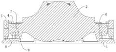
图3是实施例1的剖视图;Fig. 3 is the sectional view of
图4是实施例1的爆炸示意图;Fig. 4 is the explosion schematic diagram of
图5是安装台与绕线块安装示意图Figure 5 is a schematic diagram of the installation of the installation platform and the winding block
图6是镜头及安装台的示意图;6 is a schematic diagram of a lens and a mounting table;
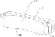
图7是线圈及绕线块的示意图;7 is a schematic diagram of a coil and a winding block;
图8是上弹簧的示意图;Fig. 8 is the schematic diagram of the upper spring;
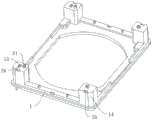
图9是底座的示意图;Fig. 9 is the schematic diagram of the base;
图10是实施例2的爆炸示意图。FIG. 10 is an exploded schematic diagram of Example 2. FIG.
图中数字所表示的相应部件名称:1、底座;2、镜头;3、上弹簧;301、上弹簧A;302、上弹簧B组;3021、上弹簧B分件;4、线圈;5、磁石;6、安装台;7、绕线块;8、绕线槽;9、卡槽;10、缺口;11、绕线柱;12、定位槽;13、定位柱;14、凸台;15、接线端子;16、焊接孔;17、凸起;18、让位槽;19、第一固定柱;20、第一固定孔;21、第二固定柱;22、第二固定孔;23、连接孔;24、容纳槽;25、点胶缺口;26、下弹簧;27、穿设柱;28、穿设孔。The names of the corresponding parts indicated by the numbers in the figure: 1, base; 2, lens; 3, upper spring; 301, upper spring A; 302, upper spring B group; 3021, upper spring B part; 4, coil; 5, Magnet; 6. Mounting platform; 7. Winding block; 8. Winding slot; 9. Card slot; 10. Notch; 11. Winding column; 12. Positioning slot; 13. Positioning column; 14. Boss; 15 , terminal; 16, welding hole; 17, protrusion; 18, give way slot; 19, first fixing column; 20, first fixing hole; 21, second fixing column; 22, second fixing hole; 23, Connection hole; 24, accommodating groove; 25, dispensing gap; 26, lower spring; 27, piercing column; 28, piercing hole.
具体实施方式Detailed ways
为了使本发明实现的技术手段、创作特征、达成目的与功效易于明白了解,下面结合图示与具体实施例,进一步阐述本发明。In order to make the technical means, creation features, achievement goals and effects realized by the present invention easy to understand, the present invention will be further described below with reference to the drawings and specific embodiments.
实施例1:如图1至9所示,本发明提出的一种镜头一体马达的端子焊接结构,包括底座1、镜头2、上弹簧3、线圈4、磁石5。镜头2一体成型有安装台6,安装台6与线圈4之间安装有绕线块7,绕线块7开设有供线圈4绕设的绕线槽8,线圈4绕设并固定于绕线块7,绕线槽8呈环绕绕线块7设置,且绕线块7环形中心线垂直于镜头2中心线方向。并且本实施例中,线圈4、绕线块7及磁石5均设置为两个,且对称设置于镜头2两侧。Embodiment 1: As shown in FIGS. 1 to 9 , a terminal welding structure of a lens-integrated motor proposed by the present invention includes a
本实施例中,绕线块7卡接于镜头2侧壁,并且安装台6侧壁开设有供绕线块7部分卡入的卡槽9,卡槽9开设于安装台6侧壁与上表面之间,在卡槽9两侧侧壁均开设有缺口10,缺口10贯穿安装台6上表面。绕线块7下端面抵接于卡槽9下底面,且绕线块7两侧壁均一体成型有供线圈4两端绕设的绕线柱11,绕线柱11呈T字形设置,绕线柱11位于缺口10内,并且线圈4两端分别绕于绕线柱11上。In this embodiment, the
在卡槽9与绕线块7之间设置有限制绕线块7脱离镜头2的限位组件,本实施例中,限位组件设置为两组,两组限位组件呈对称设置,每组限位组件均包括开设于卡槽9下底面的定位槽12、一体成型于绕线块7下端面并插设于定位槽12的定位柱13。Between the
在将线圈4安装于镜头2时,预先将线圈4绕设于绕线槽8,且线圈4两端分别绕设于两个绕线柱11,实现线圈4与绕线块7模块化预组装,然后将绕线块7卡入卡槽9内,并使定位柱13插设于定位槽12内,从而实现将绕线块7固定于镜头2上;通过线圈4单独固定于绕线块7,实现线圈4直绕,避免预先上锡及线圈4整理;通过绕线块7直接插入镜头2的安装块上,可有效改善线圈4与镜头2配合误差大的问题,并提高精度,及产品合格率,同时简化工艺的作用。When installing the
本实施例中,绕线块7朝向镜头2中心的表面呈弧形设置且贴合与卡槽9侧壁,且圆弧形中心位于镜头2中心线位置。In this embodiment, the surface of the winding
在本实施例中,底座1四个边角位置均一体成型有凸台14,并且底座1还安装有两个接线端子15,两个接线端子15呈竖直设置且分别穿设于对应的两个凸台14,两个接线端子15位于底座1同一侧壁的两个边角位置。在注塑底座1时,接线端子15预设于底座1,实现接线端子15固定于底座1。In this embodiment, the four corners of the
本实施例中,上弹簧3包括上弹簧A301、上弹簧B组302,上弹簧A301与上弹簧B组302呈对称设置于镜头2两侧,且上弹簧A301与上弹簧B组302分隔开。并且上弹簧B组302包括两个呈相对设置的上弹簧B分件3021,两个上弹簧B分件3021呈分隔设置。上弹簧A301及两个上弹簧B分件3021均安装于安装台6上表面及凸台14上表面之间,并且上弹簧A301与两个绕线块7对应的绕线柱11连接,两个上弹簧B分件3021分别与另外两个绕线柱11连接,即上弹簧A301及上弹簧B分件3021接均位于对应绕线柱11上方,并且上弹簧A301及上弹簧B分件3021抵绕设于绕线柱11的线圈4端部铜线;同时两个上弹簧B分件3021分别与对应的接线端子15。在将绕线块7组装与安装台6时,绕线块7由上而下卡入卡槽9内进行固定的,再通过上弹簧A301及上弹簧B分件3021抵接于绕线柱11及对应线圈4端部,并进行焊接,可以进行部固定绕线块7,避免绕线块7脱落,提高了本申请的结构强度;本申请中的电流流向为:电流由一个接线端子15进入所连接的一个上弹簧B分件3021,经过所相连的线圈4后进入上弹簧A301,然后由上弹簧A301进入另一个线圈4,后经过另一上弹簧B分件3021后,从另一个端子流出。In this embodiment, the
在本实施例中,进一步设置为:上弹簧A301、上弹簧B分件3021均开设有焊接孔16,焊接孔16位于对应绕线柱11正上方。绕设于绕线柱11的线圈4端部设置有焊接料,焊接料材质可以为锡膏或导电胶,焊接料位于焊接孔16内并与对应的上弹簧A301或上弹簧B分件3021连接。In this embodiment, it is further configured that the upper spring A301 and the upper
在组装时,线圈4绕于绕线块7,并且线圈4两端线头分别绕于绕线柱11后,线圈4线头上部表面进行激光去除漆包层,然后预先点焊接料(锡膏或导电胶)在焊接位置,后将绕线块7插接于安装台6,上弹簧A301及上弹簧B分件3021插接于安装台6时,上弹簧A301及上弹簧B分件3021抵接于对应线圈4两端线头,且焊接料正好位于焊接孔16内,对焊接料进行加热后,上弹簧A301及上弹簧B分件3021与对应绕线柱11线圈4线头焊接,实现电性导通。During assembly, the
本实施例中,焊接孔16内侧壁设置有增加与焊接料接触面的凸起17,凸起17可以设置为两个且呈相对设置。通过凸起17实现增加焊接孔16内侧壁的面积,进而增加焊接料与焊接孔16内壁焊接面积,有效避免虚焊、焊接不牢的问题。In this embodiment, the inner side wall of the
本实施例中,为方便镜头2及安装台6相对于底座1移动,并避免与上弹簧3产生干涉情况,安装台6开设有方便上弹簧A301、上弹簧B分件3021弹性移动的让位槽18。通过让位槽18,可以实现有效避免上弹簧A301、上弹簧B分件3021与安装台6接触,并避免后期使用时出现故障。In this embodiment, in order to facilitate the movement of the
为方便对上弹簧A301及上弹簧B分件3021进行安装定位,凸台14与对应的上弹簧A301或上弹簧B分件3021之间设置有第一固定组件,安装台6与上弹簧A301及上弹簧B分件3021均设置有第二固定组件。第一固定组件包括一体成型于凸台14上表面的第一固定柱19、开设于上弹簧A301或上弹簧B分件3021并套设于第一固定柱19的第一固定孔20;第二固定组包括一体成型安装台6上表面的第二固定柱21、开设于上弹簧A301或上弹簧B分件3021并套设于第一固定柱19的第二固定孔22。在本实施例中,上弹簧A301开设有四个第一固定孔20,且呈间隔设置,上弹簧B分件3021开设有两个第一固定孔20;安装台6上端面一体成型有八个第一固定柱19并分别穿设于对应第一固定孔20。通过第一固定孔20、第一固定柱19、第二固定孔22、第二固定柱21,可以有效定位上弹簧A301及上弹簧B分件3021相对于安装台6及凸台14的安装位置,提高本申请的组装精度,并可以有效提高上弹簧A301及上弹簧B分件3021的固定强度。In order to facilitate the installation and positioning of the upper spring A301 and the upper
本实施例中,为确保上弹簧B分件3021与接线端子15焊接固定,两个接线端子15突出于对应凸台14的上表面。上弹簧B分件3021开设有供接线端子15穿设的连接孔23,连接孔23与接线端子15之间设置有焊接料。并且凸台14上端面开设有与连接孔23相对应的容纳槽24,接线端子15穿设于容纳槽24,焊接料位于容纳槽24位置。在将上弹簧B分件3021与凸台14安装固定并与对应接线端子15连接时,连接孔23套设于对应接线端子15,然后对接线端子15突出部分与上弹簧B分件3021通过焊接料焊接,焊接料填充于容纳槽24即连接孔23,达到确保接线端子15与上弹簧B分件3021有效焊接,避免上弹簧B分件3021固定不到位存在虚焊及击穿开路的风险,并且通过容纳槽24及连接孔23,实现焊接位置一致性好,并改善焊接空间不足的问题;同时通过焊接进一步增加上弹簧B分件3021与凸台14固定安装强度。In this embodiment, in order to ensure that the upper
凸台14上端面的侧边开设有点胶缺口25,点胶缺口25延伸至对应上弹簧A301或上弹簧B分件3021正下方。通过在点胶缺口25位置进行点胶固定,方便将上弹簧A301或上弹簧B分件3021固定于对应凸台14,提高上弹簧A301及上弹簧B分件3021固定强度。A
实施例2,一种音圈马达,如图10所示,具有实施例1的镜头一体马达的端子焊接结构,并且还包括设置于安装台6下端面与底座1之间的下弹簧26,底座1设置有穿设于下弹簧26并定位下弹簧26的穿设柱27,下弹簧26开设有供穿设柱27穿设的穿设孔28,穿设柱27上端面抵接于磁石5下端面并定位磁石5位置,穿设柱27设置为四个且呈两两对称。下弹簧26套设于穿设柱27并固定在底座1,通过穿设柱27有效定位下弹簧26的安装位置,并且通过穿设柱27上端面抵接于磁石5下端面,达到有效定位磁石5相对于底座1位置,确保磁石5与线圈4位于同一平面位置,提高音圈马达安装精度,减小装配误差。
实施例3,一种照相装置,具有实施例1所述的镜头一体马达的端子焊接结构。
实施例4,一种电子产品,具有实施例1所述的镜头一体马达的端子焊接结构。
在本文中,术语“上”、“下”、“前”、“后”、“左”、“右”、“顶”、“底”、“内”、“外”、“竖直”、“水平”等指示的方位或位置关系为基于附图所示的方位或位置关系,仅是为了表达技术方案的清楚及描述方便,因此不能理解为对本发明的限制。In this document, the terms "upper", "lower", "front", "rear", "left", "right", "top", "bottom", "inner", "outer", "vertical", The orientation or positional relationship indicated by "horizontal" is based on the orientation or positional relationship shown in the accompanying drawings, which is only for the clarity of expressing the technical solution and the convenience of description, and therefore should not be construed as a limitation of the present invention.
在本文中,术语“包括”、“包含”或者其任何其他变体意在涵盖非排他性的包含,除了包含所列的那些要素,而且还可包含没有明确列出的其他要素。As used herein, the terms "comprising", "comprising" or any other variation thereof are intended to encompass non-exclusive inclusion, in addition to those elements listed, but also other elements not expressly listed.
以上显示和描述了本发明的基本原理、主要特征和本发明的优点。本行业的技术人员应该了解,本发明不受上述实施例的限制,上述实施例和说明书中描述的只是说明本发明的原理,在不脱离本发明精神和范围的前提下本发明还会有各种变化和改进,这些变化和改进都落入要求保护的本发明范围内。本发明要求保护范围由所附的权利要求书及其等同物界定。The foregoing has shown and described the basic principles, main features and advantages of the present invention. Those skilled in the art should understand that the present invention is not limited by the above-mentioned embodiments. The above-mentioned embodiments and descriptions only illustrate the principle of the present invention. Such changes and improvements fall within the scope of the claimed invention. The claimed scope of the present invention is defined by the appended claims and their equivalents.
Claims (9)
Translated fromChinesePriority Applications (1)
| Application Number | Priority Date | Filing Date | Title |
|---|---|---|---|
| CN202010364495.1ACN111431375A (en) | 2020-04-30 | 2020-04-30 | A terminal welding structure of a lens-integrated motor, a voice coil motor, and a camera device |
Applications Claiming Priority (1)
| Application Number | Priority Date | Filing Date | Title |
|---|---|---|---|
| CN202010364495.1ACN111431375A (en) | 2020-04-30 | 2020-04-30 | A terminal welding structure of a lens-integrated motor, a voice coil motor, and a camera device |
Publications (1)
| Publication Number | Publication Date |
|---|---|
| CN111431375Atrue CN111431375A (en) | 2020-07-17 |
Family
ID=71552275
Family Applications (1)
| Application Number | Title | Priority Date | Filing Date |
|---|---|---|---|
| CN202010364495.1APendingCN111431375A (en) | 2020-04-30 | 2020-04-30 | A terminal welding structure of a lens-integrated motor, a voice coil motor, and a camera device |
Country Status (1)
| Country | Link |
|---|---|
| CN (1) | CN111431375A (en) |
Citations (8)
| Publication number | Priority date | Publication date | Assignee | Title |
|---|---|---|---|---|
| CN204216763U (en)* | 2014-12-02 | 2015-03-18 | 东莞市东勤电子有限公司 | An anti-deformation stable voice coil motor spring piece |
| CN206039113U (en)* | 2016-08-15 | 2017-03-22 | 深圳市世尊科技有限公司 | But optical anti -vibration voice coil motor of components of a whole that can function independently control |
| CN207366907U (en)* | 2017-08-23 | 2018-05-15 | 上海比路电子股份有限公司 | A kind of camera gun driving device |
| CN108249385A (en)* | 2018-01-15 | 2018-07-06 | 烟台艾睿光电科技有限公司 | A kind of MEMS package weld assembly |
| CN208079381U (en)* | 2018-04-08 | 2018-11-09 | 江西联创宏声电子股份有限公司 | Loud speaker module |
| CN110365888A (en)* | 2013-11-05 | 2019-10-22 | Lg伊诺特有限公司 | camera module |
| CN210401812U (en)* | 2019-09-23 | 2020-04-24 | 新思考电机有限公司 | Driving device, camera module and electronic equipment |
| CN211959039U (en)* | 2020-04-30 | 2020-11-17 | 新思考电机有限公司 | Terminal welding structure, voice coil motor, photographic device and electronic product |
- 2020
- 2020-04-30CNCN202010364495.1Apatent/CN111431375A/enactivePending
Patent Citations (8)
| Publication number | Priority date | Publication date | Assignee | Title |
|---|---|---|---|---|
| CN110365888A (en)* | 2013-11-05 | 2019-10-22 | Lg伊诺特有限公司 | camera module |
| CN204216763U (en)* | 2014-12-02 | 2015-03-18 | 东莞市东勤电子有限公司 | An anti-deformation stable voice coil motor spring piece |
| CN206039113U (en)* | 2016-08-15 | 2017-03-22 | 深圳市世尊科技有限公司 | But optical anti -vibration voice coil motor of components of a whole that can function independently control |
| CN207366907U (en)* | 2017-08-23 | 2018-05-15 | 上海比路电子股份有限公司 | A kind of camera gun driving device |
| CN108249385A (en)* | 2018-01-15 | 2018-07-06 | 烟台艾睿光电科技有限公司 | A kind of MEMS package weld assembly |
| CN208079381U (en)* | 2018-04-08 | 2018-11-09 | 江西联创宏声电子股份有限公司 | Loud speaker module |
| CN210401812U (en)* | 2019-09-23 | 2020-04-24 | 新思考电机有限公司 | Driving device, camera module and electronic equipment |
| CN211959039U (en)* | 2020-04-30 | 2020-11-17 | 新思考电机有限公司 | Terminal welding structure, voice coil motor, photographic device and electronic product |
Similar Documents
| Publication | Publication Date | Title |
|---|---|---|
| CN110572005B (en) | voice coil motor | |
| US9891403B2 (en) | Motor for driving lenses | |
| US9341809B2 (en) | Lens focusing device | |
| US20140256379A1 (en) | Lens holding device | |
| CN109212710B (en) | Lens driving system and circuit module thereof | |
| JPWO2013054727A1 (en) | Power control device | |
| CN118248429B (en) | Magnetic component and assembly method thereof, linear motor, camera, and electronic equipment | |
| CN207301452U (en) | Optical drive mechanism | |
| CN209560246U (en) | Driving device, camera mould group and electronic equipment | |
| CN107533209B (en) | lens drive | |
| CN209281052U (en) | Lens driver and camara module | |
| CN111416497A (en) | A motor, camera device and electronic product with integral lens and side winding | |
| CN209265050U (en) | Lens driving device and camera module | |
| CN113452233B (en) | High-thrust middle-mounted automatic focusing motor | |
| CN112130397B (en) | Lens module and electronic equipment | |
| CN111431375A (en) | A terminal welding structure of a lens-integrated motor, a voice coil motor, and a camera device | |
| WO2021000161A1 (en) | Lens module | |
| CN211655962U (en) | Voice coil motor | |
| CN211959039U (en) | Terminal welding structure, voice coil motor, photographic device and electronic product | |
| CN211701816U (en) | Camera lens integrated motor with side winding, camera device and electronic product | |
| CN111431374A (en) | A spring welding structure of a lens-integrated motor, a voice coil motor, and a camera device | |
| CN111722454B (en) | Driving device, camera module, electronic device and driving device assembly method | |
| JPWO2018123815A1 (en) | Lens drive | |
| CN114173037B (en) | Driving assembly, camera module and electronic equipment | |
| CN212063805U (en) | Spring welded structure, voice coil motor, photographic arrangement, electronic product |
Legal Events
| Date | Code | Title | Description |
|---|---|---|---|
| PB01 | Publication | ||
| PB01 | Publication | ||
| SE01 | Entry into force of request for substantive examination | ||
| SE01 | Entry into force of request for substantive examination |