CN111421529B - A control method of a rope-driven flexible arm - Google Patents
A control method of a rope-driven flexible armDownload PDFInfo
- Publication number
- CN111421529B CN111421529BCN202010164603.0ACN202010164603ACN111421529BCN 111421529 BCN111421529 BCN 111421529BCN 202010164603 ACN202010164603 ACN 202010164603ACN 111421529 BCN111421529 BCN 111421529B
- Authority
- CN
- China
- Prior art keywords
- flexible arm
- rope
- working end
- rope length
- driving
- Prior art date
- Legal status (The legal status is an assumption and is not a legal conclusion. Google has not performed a legal analysis and makes no representation as to the accuracy of the status listed.)
- Active
Links
Images


Classifications
- B—PERFORMING OPERATIONS; TRANSPORTING
- B25—HAND TOOLS; PORTABLE POWER-DRIVEN TOOLS; MANIPULATORS
- B25J—MANIPULATORS; CHAMBERS PROVIDED WITH MANIPULATION DEVICES
- B25J9/00—Programme-controlled manipulators
- B25J9/10—Programme-controlled manipulators characterised by positioning means for manipulator elements
- B25J9/104—Programme-controlled manipulators characterised by positioning means for manipulator elements with cables, chains or ribbons
- B—PERFORMING OPERATIONS; TRANSPORTING
- B25—HAND TOOLS; PORTABLE POWER-DRIVEN TOOLS; MANIPULATORS
- B25J—MANIPULATORS; CHAMBERS PROVIDED WITH MANIPULATION DEVICES
- B25J13/00—Controls for manipulators
- B25J13/08—Controls for manipulators by means of sensing devices, e.g. viewing or touching devices
- B25J13/085—Force or torque sensors
- B—PERFORMING OPERATIONS; TRANSPORTING
- B25—HAND TOOLS; PORTABLE POWER-DRIVEN TOOLS; MANIPULATORS
- B25J—MANIPULATORS; CHAMBERS PROVIDED WITH MANIPULATION DEVICES
- B25J19/00—Accessories fitted to manipulators, e.g. for monitoring, for viewing; Safety devices combined with or specially adapted for use in connection with manipulators
- B25J19/02—Sensing devices
- B25J19/04—Viewing devices
- B—PERFORMING OPERATIONS; TRANSPORTING
- B25—HAND TOOLS; PORTABLE POWER-DRIVEN TOOLS; MANIPULATORS
- B25J—MANIPULATORS; CHAMBERS PROVIDED WITH MANIPULATION DEVICES
- B25J9/00—Programme-controlled manipulators
- B25J9/16—Programme controls
- B25J9/1628—Programme controls characterised by the control loop
- B25J9/1635—Programme controls characterised by the control loop flexible-arm control
Landscapes
- Engineering & Computer Science (AREA)
- Robotics (AREA)
- Mechanical Engineering (AREA)
- Human Computer Interaction (AREA)
- Manipulator (AREA)
Abstract
Translated fromChinese
Description
Translated fromChinese技术领域technical field
本发明涉及绳驱机器人领域,尤其是涉及一种绳驱柔性臂的控制方法。The invention relates to the field of rope-driven robots, in particular to a control method of a rope-driven flexible arm.
背景技术Background technique
目前,由于远程操作可以有效保护操作人员的安全,使操作过程更加便捷,远程操作被广泛运用于有毒环境设备修理、有毒化工废料处理、微创手术等环境中。但是,在机械臂领域,通常仅能对刚性臂进行远程控制,无法对柔性臂进行远程控制。At present, because remote operation can effectively protect the safety of operators and make the operation process more convenient, remote operation is widely used in toxic environment equipment repair, toxic chemical waste treatment, minimally invasive surgery and other environments. However, in the field of robotic arms, usually only rigid arms can be remotely controlled, and flexible arms cannot be remotely controlled.
发明内容SUMMARY OF THE INVENTION
本发明旨在至少解决现有技术中存在的技术问题之一。为此,本发明提出一种绳驱柔性臂的控制方法,能够远程控制绳驱柔性臂进行运动,在一些有害环境中使用时能够提高安全性。The present invention aims to solve at least one of the technical problems existing in the prior art. To this end, the present invention proposes a control method for a rope-driven flexible arm, which can remotely control the rope-driven flexible arm to move, and can improve safety when used in some harmful environments.
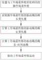
本发明的一个实施例提供了绳驱柔性臂的控制方法,用于对工作端柔性臂进行远程控制,包括如下步骤:An embodiment of the present invention provides a control method for a rope-driven flexible arm, which is used to remotely control the working end flexible arm, including the following steps:
S10设置操作端柔性臂,所述操作端柔性臂的形状与所述工作端柔性臂相同,且所述工作端柔性臂与所述操作端柔性臂的尺寸比例为k;S10 set an operation end flexible arm, the shape of the operation end flexible arm is the same as that of the working end flexible arm, and the size ratio of the working end flexible arm and the operation end flexible arm is k;
S20获取所述操作端柔性臂的驱动绳的绳长变化量Δl;S20 obtains the change amount Δ1 of the rope length of the driving rope of the flexible arm of the operation end;
S30计算所述工作端柔性臂的驱动绳的绳长变化量Δl′,Δl′=k·Δl;S30 calculates the rope length variation Δl' of the driving rope of the flexible arm at the working end, Δl'=k·Δl;
S40根据绳长变化量计算所述工作端柔性臂的驱动绳的绳长-时间函数;S40 calculates the rope length-time function of the driving rope of the working end flexible arm according to the rope length variation;
S50根据绳长-时间函数驱动所述工作端柔性臂运动。S50 drives the flexible arm of the working end to move according to the rope length-time function.
本发明实施例的绳驱柔性臂的控制方法至少具有如下有益效果:由于操作端柔性臂与工作端柔性臂形状相同且尺寸成比例,因此,当操作端柔性臂到达某一位姿时,工作端柔性臂也会随之按比例运动。获取操作端柔性臂的绳长变化量后,按比例换算即可得出工作端柔性臂的绳长变化量,然后根据绳长变化量求得绳长与时间之间的函数关系,并按照该函数关系驱动工作端柔性臂运动即可。The control method of the rope-driven flexible arm according to the embodiment of the present invention has at least the following beneficial effects: since the flexible arm at the operating end and the flexible arm at the working end have the same shape and are proportional in size, when the flexible arm at the working end reaches a certain posture, the The end flexible arm also moves proportionally. After obtaining the change of the rope length of the flexible arm at the operating end, the change of the rope length of the flexible arm at the working end can be obtained by proportional conversion, and then the functional relationship between the rope length and time can be obtained according to the change of the rope length. The functional relationship can drive the movement of the flexible arm at the working end.
根据本发明的另一些实施例的绳驱柔性臂的控制方法,获取所述操作端柔性臂的驱动绳的绳长变化量Δl的方法为:设置绳长编码器,通过所述绳长编码器获取所述操作端柔性臂的驱动绳的绳长变化量Δl。According to the control method of the rope-driven flexible arm according to other embodiments of the present invention, the method for obtaining the rope length variation Δl of the driving rope of the flexible arm at the operating end is: setting a rope length encoder, and using the rope length encoder Obtain the change amount Δl of the rope length of the driving rope of the flexible arm at the operating end.
根据本发明的另一些实施例的绳驱柔性臂的控制方法,通过所述绳长编码器获取与所述操作端柔性臂的驱动绳连接的滑轮的转动圈数q,所述滑轮的半径为r,Δl=πrq。According to the control method of the rope-driven flexible arm according to other embodiments of the present invention, the number of rotations q of the pulley connected to the drive rope of the flexible arm at the operating end is obtained through the rope length encoder, and the radius of the pulley is r, Δl=πrq.
根据本发明的另一些实施例的绳驱柔性臂的控制方法,获取所述操作端柔性臂的驱动绳的绳长变化量Δl的方法为:设置角度编码器,通过所述角度编码器获取所述操作端柔性臂的关节角,并通过关节角计算获得所述操作端柔性臂的驱动绳的绳长变化量Δl。According to the control method of a rope-driven flexible arm according to other embodiments of the present invention, the method for obtaining the change Δl of the rope length of the driving rope of the flexible arm at the operating end is as follows: setting an angle encoder, and obtaining all the information from the angle encoder through the angle encoder. The joint angle of the flexible arm at the operation end is calculated, and the change amount Δl of the rope length of the driving rope of the flexible arm at the operation end is obtained by calculating the joint angle.
根据本发明的另一些实施例的绳驱柔性臂的控制方法,对所述工作端柔性臂的驱动绳的绳长变化量进行三次样条插值法以获得绳长-时间函数。According to the control method of a rope-driven flexible arm according to other embodiments of the present invention, a cubic spline interpolation method is performed on the rope length variation of the driving rope of the working end flexible arm to obtain a rope length-time function.
根据本发明的另一些实施例的绳驱柔性臂的控制方法,在步骤S40与S50之间还包括步骤S41:将所述绳长-时间函数划分为多个区间,求出各个区间内的绳长变化量。According to the control method of the rope-driven flexible arm according to other embodiments of the present invention, between the steps S40 and S50, a step S41 is further included: dividing the rope length-time function into a plurality of intervals, and obtaining the rope length in each interval. long variation.
根据本发明的另一些实施例的绳驱柔性臂的控制方法,设置视觉导引系统,通过所述视觉导引系统获取所述工作端柔性臂的位姿。According to the control method of the rope-driven flexible arm according to other embodiments of the present invention, a vision guidance system is provided, and the pose of the working end flexible arm is acquired through the vision guidance system.
根据本发明的另一些实施例的绳驱柔性臂的控制方法,所述工作端柔性臂与所述操作端柔性臂之间通过通信模块实现通信。According to the control method of the rope-driven flexible arm according to other embodiments of the present invention, the communication between the flexible arm at the working end and the flexible arm at the operating end is realized through a communication module.
根据本发明的另一些实施例的绳驱柔性臂的控制方法,设置拉力传感器,使所述拉力传感器与所述工作端柔性臂的驱动绳串联。According to the control method of the rope-driven flexible arm according to other embodiments of the present invention, a tension sensor is provided, and the tension sensor is connected in series with the driving rope of the flexible arm at the working end.
附图说明Description of drawings
图1是第一实施例中绳驱柔性臂的控制方法流程图;Fig. 1 is the control method flow chart of the rope-driven flexible arm in the first embodiment;
图2是第一实施例中绳驱柔性臂的控制装置示意图(省略了部分部件);FIG. 2 is a schematic diagram of the control device of the rope-driven flexible arm in the first embodiment (some parts are omitted);
图3是第一实施例中操作端柔性臂的装置示意图;3 is a schematic diagram of the device of the flexible arm at the operating end in the first embodiment;
图4是第一实施例中工作端柔性臂的装置示意图。FIG. 4 is a schematic diagram of the device of the working end flexible arm in the first embodiment.
具体实施方式Detailed ways
以下将结合实施例对本发明的构思及产生的技术效果进行清楚、完整地描述,以充分地理解本发明的目的、特征和效果。显然,所描述的实施例只是本发明的一部分实施例,而不是全部实施例,基于本发明的实施例,本领域的技术人员在不付出创造性劳动的前提下所获得的其他实施例,均属于本发明保护的范围。The concept of the present invention and the technical effects produced will be clearly and completely described below with reference to the embodiments, so as to fully understand the purpose, characteristics and effects of the present invention. Obviously, the described embodiments are only a part of the embodiments of the present invention, rather than all the embodiments. Based on the embodiments of the present invention, other embodiments obtained by those skilled in the art without creative efforts are all within the scope of The scope of protection of the present invention.
在本发明实施例的描述中,如果涉及到方位描述,例如“上”、“下”、“前”、“后”、“左”、“右”等指示的方位或位置关系为基于附图所示的方位或位置关系,仅是为了便于描述本发明和简化描述,而不是指示或暗示所指的装置或元件必须具有特定的方位、以特定的方位构造和操作,因此不能理解为对本发明的限制。In the description of the embodiments of the present invention, if the orientation description is involved, for example, the orientation or positional relationship indicated by "up", "down", "front", "rear", "left", "right", etc. is based on the accompanying drawings The orientation or positional relationship shown is only for the convenience of describing the present invention and simplifying the description, rather than indicating or implying that the indicated device or element must have a specific orientation, be constructed and operated in a specific orientation, and therefore should not be construed as a reference to the present invention. limits.
在本发明实施例的描述中,如果某一特征被称为“设置”、“固定”、“连接”、“安装”在另一个特征,它可以直接设置、固定、连接在另一个特征上,也可以间接地设置、固定、连接、安装在另一个特征上。在本发明实施例的描述中,如果涉及到“若干”,其含义是一个以上,如果涉及到“多个”,其含义是两个以上,如果涉及到“大于”、“小于”、“超过”,均应理解为不包括本数,如果涉及到“以上”、“以下”、“以内”,均应理解为包括本数。如果涉及到“第一”、“第二”,应当理解为用于区分技术特征,而不能理解为指示或暗示相对重要性或者隐含指明所指示的技术特征的数量或者隐含指明所指示的技术特征的先后关系。In the description of the embodiments of the present invention, if a feature is referred to as "set", "fixed", "connected", "installed" on another feature, it can be directly set, fixed, or connected on another feature, It can also be indirectly disposed, fixed, connected, mounted on another feature. In the description of the embodiments of the present invention, if "several" is involved, it means more than one; if it involves "plurality", it means more than two; ", should be understood as not including this number, if it involves "above", "below", "within", it should be understood as including this number. If it refers to "first" and "second", it should be understood to be used to distinguish technical features, but not to indicate or imply relative importance, or to imply indicate the number of indicated technical features or to imply indicate the indicated The sequence of technical features.
第一实施例first embodiment
参照图1与图2,分别示出了第一实施例中绳驱柔性臂的控制方法流程图与绳驱柔性臂的控制装置示意图。该装置示意图中仅示出了与一个关节相连的4根驱动绳及滑轮等部件,其他关节与该关节处的设置方式类似,图中将其省略。操作端柔性臂100与工作端柔性臂200之间通过通信模块进行信息传输,具体的,可以是有线网络,或者4G网络,或者5G网络。操作端柔性臂100与工作端柔性臂200的形状相同,且工作端柔性臂与操作端柔性臂的尺寸比例为k。二者间的关系类似于“相似三角形”,若二者的每个关节运动的方向与角度相同,则当操作端柔性臂100运动到达某一位姿时,工作端柔性臂200的关节角会与操作端柔性臂相同。Referring to FIG. 1 and FIG. 2 , a flowchart of a control method of a rope-driven flexible arm and a schematic diagram of a control device of the rope-driven flexible arm in the first embodiment are respectively shown. In the schematic diagram of the device, only four driving ropes, pulleys and other components connected to one joint are shown, and other joints are arranged in a similar manner to this joint, which is omitted in the figure. Information is transmitted between the operation-end
参照图3,示出了第一实施例中操作端柔性臂的装置示意图。操作端柔性臂100包括多个操作端关节110,每两个相邻的操作端关节110之间通过操作端中心块120相连,相邻的两个操作端关节110可分别相对于二者之间的操作端中心块120朝不同方向转动。以最底部的一个操作端关节110为例,该操作端关节110与四根操作端驱动绳130相连,操作端驱动绳130绕过操作端滑轮140,且在其端部挂有重物以使其绷直。在操作端驱动绳130上还设有绳长编码器150,用于获取绳长变化量。本实施例中,与每个操作端关节110相连的操作端驱动绳130有四根,但不限于此,其数量只需大于关节运动的自由度即可。Referring to FIG. 3 , a schematic diagram of the device of the flexible arm at the operating end in the first embodiment is shown. The operation-end
参照图4,示出了第一实施例中工作端柔性臂的装置示意图。工作端柔性臂200包括多个工作端关节210,每两个相邻的工作端关节210之间通过工作端中心块220相连,相邻的两个工作端关节210可分别相对于二者之间的工作端中心块220朝不同方向转动。以最底部的一个工作端关节210为例,该工作端关节210与四根工作端驱动绳230相连,工作端驱动绳230缠绕在工作端滑轮240上,且工作端滑轮240与电机250相连,其能在电机250的驱动下进行转动,以收回或放出一段工作端驱动绳230。另外,在工作端驱动绳230上还串联有拉力传感器260,用于监测工作端驱动绳230的拉力是否处于正常范围内。Referring to FIG. 4 , a schematic diagram of the device of the working end flexible arm in the first embodiment is shown. The working-end
通过操作端柔性臂100控制工作端柔性臂200运动时,需要先获取操作端驱动绳130的绳长变化量。设共有p根操作端驱动绳(用驱动端关节110的数量乘以与每个驱动端关节110相连的操作端驱动绳130的数量得出),工作端驱动绳230的数量与其相同。操作端柔性臂100朝着工作端柔性臂200末端需要运动的方向运动,操作端驱动绳130被拉动或放出,并带动操作端滑轮140转动。When controlling the movement of the working end
首先等时间间隔Δt采集操作端驱动绳130的绳长变化量。操作端滑轮140的半径为r,通过绳长编码器150记录与第i根操作端驱动绳130相连的操作端滑轮140的旋转圈数qi,从而获取第tj时刻遥控装置绳长的变化量:First, at equal time intervals Δt, the rope length variation of the driving

由此可获得运动过程中操作端柔性臂100的全部绳长变化量:In this way, the entire rope length variation of the

因此,工作端柔性臂200达到相同位姿时全部工作端驱动绳230的绳长变化量为:Therefore, when the working end

将上述工作端驱动绳230的绳长变化量传至工作端柔性臂200,通过三次样条插值法获取工作端柔性臂200的绳长-时间曲线函数。根据公式(3)可知,工作端柔性臂200的第i根工作端驱动绳230的绳长变化量为The rope length variation of the working

设在第j个节点上的绳长变化加速度为mj;The acceleration of rope length change at the jth node is mj ;
计算步长h=Δt;共有n+1个节点,t0=0,
为使运动曲线平滑,运动过程中首尾两段绳的加速度取0,即m0=mn=0,则三次样条曲线方程组为:In order to make the motion curve smooth, the acceleration of the first and last two ropes is set to 0 during the motion, that is, m0 =mn =0, then the cubic spline curve equation system is:

求解矩阵方程(5),计算三次样条曲线系数为:Solving the matrix equation (5), the cubic spline coefficients are calculated as:


cu=mu/2 (8)cu =mu /2 (8)

其中u=0,1,2,…,n-1;where u=0, 1, 2, ..., n-1;
根据公式(6)、(7)、(8)、(9)得,在子区间t∈(uΔt,(u+1)Δt)中,According to formulas (6), (7), (8), (9), in the sub-interval t∈(uΔt, (u+1)Δt),
Δl′i=au+bu(t-uΔt)+cu(t-uΔt)2+du(t-uΔt)3 (10)Δl′i =au +bu (t-uΔt)+cu (t-uΔt)2 +du (t-uΔt)3 (10)
将每个子区间Δl′i函数合并则获得工作端柔性臂200的第i根工作端驱动绳230的绳长-时间曲线。可根据此方法求得所有工作端驱动绳的绳长-时间曲线。The rope length-time curve of the i-th working
为了提高运动的精确度,优选的,以更小的时间间距Δt’等间距划分绳长-时间曲线,求出新的工作端驱动绳230的绳长变化量节点。设工作端柔性臂200第i根工作端驱动绳230的绳长变化量的新节点为In order to improve the accuracy of the movement, preferably, the rope length-time curve is divided into equal intervals with a smaller time interval Δt', and a new rope length variation node of the driving

则当t∈(u′Δt′,(u′+1)Δt′)(u′=0,1,2,…,n′-1)时,工作端柔性臂200的第i根工作端驱动绳230的绳长变化量为


第i根工作端驱动绳230对应的电机250的速度为:The speed of the

在上述过程中,拉力传感器260实时测量工作端驱动绳230所受拉力值,若超过最大承受拉力值,则发送信号到操作端,使其停止运动。During the above process, the
另外,在工作端还设有视觉导引系统,用于实时获取工作端柔性臂200的位姿,以判断操作端柔性臂100所需的运动朝向,以及判断工作端柔性臂200是否有可能碰撞到外部部件。In addition, a visual guidance system is also provided at the working end, which is used to obtain the pose of the
第二实施例Second Embodiment
本实施例是第一实施例的替代实施例,在本实施例中,与第一实施例不同的是,无需设置绳长编码器150,在每两个操作端关节110之间设有关节编码器160,用于获取当前构型下这两个关节间的角度。并通过关节角求得操作端驱动绳130的绳长变化量。This embodiment is an alternative embodiment of the first embodiment. In this embodiment, unlike the first embodiment, there is no need to provide a
首先等时间间隔Δt采集运动过程中操作端柔性臂100的构型角度值,角度值与工作端柔性臂100相同;First, at equal time intervals Δt, the configuration angle value of the
根据各关节角度值确定工作端柔性臂200的构型,计算工作端柔性臂200的工作端驱动绳230绳长。现有的根据关节角计算单根驱动绳在单个子关节上绳索变化量的计算公式为:The configuration of the working end

其中,
通过公式(14),可以求出第tj时刻第i根工作端驱动绳230在单个关节的绳长变化量。将工作端柔性臂200的第tj时刻第i根工作端驱动绳230所经过的全部关节上的绳长变化量叠加,即求得第i根工作端驱动绳230在第tj时刻的绳长变化量:According to formula (14), the change of the rope length of the i-th working

由此可获得运动过程中工作端柔性臂200的全部驱动绳变化量:In this way, the entire driving rope variation of the

之后的计算过程与第一实施例相同,故不再赘述。The subsequent calculation process is the same as that of the first embodiment, so it will not be repeated.
上面结合附图对本发明实施例作了详细说明,但是本发明不限于上述实施例,在所述技术领域普通技术人员所具备的知识范围内,还可以在不脱离本发明宗旨的前提下做出各种变化。此外,在不冲突的情况下,本发明的实施例及实施例中的特征可以相互组合。The embodiments of the present invention have been described in detail above in conjunction with the accompanying drawings, but the present invention is not limited to the above-mentioned embodiments, and can also be made within the scope of knowledge possessed by those of ordinary skill in the technical field without departing from the purpose of the present invention. Various changes. Furthermore, the embodiments of the present invention and features in the embodiments may be combined with each other without conflict.
Claims (9)
Translated fromChinesePriority Applications (1)
| Application Number | Priority Date | Filing Date | Title |
|---|---|---|---|
| CN202010164603.0ACN111421529B (en) | 2020-03-11 | 2020-03-11 | A control method of a rope-driven flexible arm |
Applications Claiming Priority (1)
| Application Number | Priority Date | Filing Date | Title |
|---|---|---|---|
| CN202010164603.0ACN111421529B (en) | 2020-03-11 | 2020-03-11 | A control method of a rope-driven flexible arm |
Publications (2)
| Publication Number | Publication Date |
|---|---|
| CN111421529A CN111421529A (en) | 2020-07-17 |
| CN111421529Btrue CN111421529B (en) | 2021-08-03 |
Family
ID=71553417
Family Applications (1)
| Application Number | Title | Priority Date | Filing Date |
|---|---|---|---|
| CN202010164603.0AActiveCN111421529B (en) | 2020-03-11 | 2020-03-11 | A control method of a rope-driven flexible arm |
Country Status (1)
| Country | Link |
|---|---|
| CN (1) | CN111421529B (en) |
Families Citing this family (2)
| Publication number | Priority date | Publication date | Assignee | Title |
|---|---|---|---|---|
| CN113386124B (en)* | 2021-02-23 | 2022-12-20 | 哈尔滨工业大学(深圳) | Closed-loop motion control method and system for rope-driven flexible manipulator |
| CN115005106B (en)* | 2022-05-30 | 2023-06-20 | 北京工业大学 | An active following rigid-flexible coupling milking mechanism |
Citations (7)
| Publication number | Priority date | Publication date | Assignee | Title |
|---|---|---|---|---|
| US5784542A (en)* | 1995-09-07 | 1998-07-21 | California Institute Of Technology | Decoupled six degree-of-freedom teleoperated robot system |
| CN106272382A (en)* | 2016-08-19 | 2017-01-04 | 济南舜风科技有限公司 | Analog control system and control method for inspection robot mechanical arm |
| CN107921622A (en)* | 2015-08-25 | 2018-04-17 | 川崎重工业株式会社 | Robot system |
| CN108687773A (en)* | 2018-06-05 | 2018-10-23 | 清华大学深圳研究生院 | Flexible mechanical arm remote operating device and teleoperation method |
| CN109176494A (en)* | 2018-09-28 | 2019-01-11 | 哈尔滨工业大学(深圳) | Rope drives Arm Flexible machine people self-calibrating method and system, storage medium |
| CN110193827A (en)* | 2019-03-28 | 2019-09-03 | 南京航空航天大学 | A kind of driving compensation method for the driving non-individual body robot that restricts |
| CN110561425A (en)* | 2019-08-21 | 2019-12-13 | 哈尔滨工业大学(深圳) | Rope-driven flexible robot force and position hybrid control method and system |
Family Cites Families (1)
| Publication number | Priority date | Publication date | Assignee | Title |
|---|---|---|---|---|
| JP6410022B2 (en)* | 2013-09-06 | 2018-10-24 | パナソニックIpマネジメント株式会社 | Master-slave robot control device and control method, robot, master-slave robot control program, and integrated electronic circuit for master-slave robot control |
- 2020
- 2020-03-11CNCN202010164603.0Apatent/CN111421529B/enactiveActive
Patent Citations (7)
| Publication number | Priority date | Publication date | Assignee | Title |
|---|---|---|---|---|
| US5784542A (en)* | 1995-09-07 | 1998-07-21 | California Institute Of Technology | Decoupled six degree-of-freedom teleoperated robot system |
| CN107921622A (en)* | 2015-08-25 | 2018-04-17 | 川崎重工业株式会社 | Robot system |
| CN106272382A (en)* | 2016-08-19 | 2017-01-04 | 济南舜风科技有限公司 | Analog control system and control method for inspection robot mechanical arm |
| CN108687773A (en)* | 2018-06-05 | 2018-10-23 | 清华大学深圳研究生院 | Flexible mechanical arm remote operating device and teleoperation method |
| CN109176494A (en)* | 2018-09-28 | 2019-01-11 | 哈尔滨工业大学(深圳) | Rope drives Arm Flexible machine people self-calibrating method and system, storage medium |
| CN110193827A (en)* | 2019-03-28 | 2019-09-03 | 南京航空航天大学 | A kind of driving compensation method for the driving non-individual body robot that restricts |
| CN110561425A (en)* | 2019-08-21 | 2019-12-13 | 哈尔滨工业大学(深圳) | Rope-driven flexible robot force and position hybrid control method and system |
Also Published As
| Publication number | Publication date |
|---|---|
| CN111421529A (en) | 2020-07-17 |
Similar Documents
| Publication | Publication Date | Title |
|---|---|---|
| CN109760051B (en) | Rope length change determination method for rope-driven super-redundancy degree of freedom robot | |
| CN111421529B (en) | A control method of a rope-driven flexible arm | |
| JP6717768B2 (en) | Robot for learning control considering operation in production line and control method thereof | |
| CN106737662B (en) | Robot system | |
| CN110561425B (en) | Rope-driven flexible robot force and position hybrid control method and system | |
| CN113386124B (en) | Closed-loop motion control method and system for rope-driven flexible manipulator | |
| WO2015101088A1 (en) | Intelligent control method, device and system for multi-joint mechanical arm | |
| EP4628140A1 (en) | Catheter bending steering control method, catheter system, and storage medium | |
| CN104440870A (en) | Variable structure parameter flexible rope parallel connection robot system and control method | |
| CN108326891B (en) | A decoupling mechanism for rope-driven robotic arm joints and its decoupling method | |
| CN106695803A (en) | Continuous robot posture control system | |
| CN102649270A (en) | Robot system, robot control apparatus, and robot control method | |
| CN107053132A (en) | Modular reconfigurable Compliant Assembly variable rigidity control device and method | |
| CN108340352A (en) | The long-range real-time control method of industrial robot based on teaching joint arm | |
| CN116141319A (en) | Control method, device, equipment and storage medium of three-rope parallel robot | |
| CN102950597B (en) | Robot control system and robot control method | |
| JP2011212837A (en) | Robot system | |
| CN117863163A (en) | A compact force-position fusion measurement device based on vision | |
| CN107756388B (en) | A physical human-computer interaction platform based on rope traction and series elastic drive | |
| JPWO2019155473A5 (en) | ||
| CN110539315B (en) | Construction robot based on virtual reality control | |
| US11123861B2 (en) | Robot system | |
| JP6151857B2 (en) | Control method for controlling arm segments of a collaborative manipulator | |
| CN115723139A (en) | Method and device for operating space compliance control of a rope-driven flexible manipulator | |
| CN118089667A (en) | Robot 3D spatial positioning and guidance system based on 2D camera |
Legal Events
| Date | Code | Title | Description |
|---|---|---|---|
| PB01 | Publication | ||
| PB01 | Publication | ||
| SE01 | Entry into force of request for substantive examination | ||
| SE01 | Entry into force of request for substantive examination | ||
| GR01 | Patent grant | ||
| GR01 | Patent grant |