CN111419158A - Stereoscopic components and stereoscopic neuroendoscopes - Google Patents
Stereoscopic components and stereoscopic neuroendoscopesDownload PDFInfo
- Publication number
- CN111419158A CN111419158ACN202010266125.4ACN202010266125ACN111419158ACN 111419158 ACN111419158 ACN 111419158ACN 202010266125 ACN202010266125 ACN 202010266125ACN 111419158 ACN111419158 ACN 111419158A
- Authority
- CN
- China
- Prior art keywords
- lens
- stereoscopic
- stereoscopic endoscope
- assembly
- video
- Prior art date
- Legal status (The legal status is an assumption and is not a legal conclusion. Google has not performed a legal analysis and makes no representation as to the accuracy of the status listed.)
- Granted
Links
Images


Classifications
- A—HUMAN NECESSITIES
- A61—MEDICAL OR VETERINARY SCIENCE; HYGIENE
- A61B—DIAGNOSIS; SURGERY; IDENTIFICATION
- A61B1/00—Instruments for performing medical examinations of the interior of cavities or tubes of the body by visual or photographical inspection, e.g. endoscopes; Illuminating arrangements therefor
- A61B1/06—Instruments for performing medical examinations of the interior of cavities or tubes of the body by visual or photographical inspection, e.g. endoscopes; Illuminating arrangements therefor with illuminating arrangements
- A61B1/0661—Endoscope light sources
- A—HUMAN NECESSITIES
- A61—MEDICAL OR VETERINARY SCIENCE; HYGIENE
- A61B—DIAGNOSIS; SURGERY; IDENTIFICATION
- A61B1/00—Instruments for performing medical examinations of the interior of cavities or tubes of the body by visual or photographical inspection, e.g. endoscopes; Illuminating arrangements therefor
- A61B1/00112—Connection or coupling means
- A61B1/00117—Optical cables in or with an endoscope
- A—HUMAN NECESSITIES
- A61—MEDICAL OR VETERINARY SCIENCE; HYGIENE
- A61B—DIAGNOSIS; SURGERY; IDENTIFICATION
- A61B1/00—Instruments for performing medical examinations of the interior of cavities or tubes of the body by visual or photographical inspection, e.g. endoscopes; Illuminating arrangements therefor
- A61B1/00112—Connection or coupling means
- A61B1/00121—Connectors, fasteners and adapters, e.g. on the endoscope handle
- A61B1/00126—Connectors, fasteners and adapters, e.g. on the endoscope handle optical, e.g. for light supply cables
- A—HUMAN NECESSITIES
- A61—MEDICAL OR VETERINARY SCIENCE; HYGIENE
- A61B—DIAGNOSIS; SURGERY; IDENTIFICATION
- A61B1/00—Instruments for performing medical examinations of the interior of cavities or tubes of the body by visual or photographical inspection, e.g. endoscopes; Illuminating arrangements therefor
- A61B1/00163—Optical arrangements
- A61B1/00193—Optical arrangements adapted for stereoscopic vision
- A—HUMAN NECESSITIES
- A61—MEDICAL OR VETERINARY SCIENCE; HYGIENE
- A61B—DIAGNOSIS; SURGERY; IDENTIFICATION
- A61B1/00—Instruments for performing medical examinations of the interior of cavities or tubes of the body by visual or photographical inspection, e.g. endoscopes; Illuminating arrangements therefor
- A61B1/00163—Optical arrangements
- A61B1/00195—Optical arrangements with eyepieces
- A61B1/00197—Optical arrangements with eyepieces characterised by multiple eyepieces
- A—HUMAN NECESSITIES
- A61—MEDICAL OR VETERINARY SCIENCE; HYGIENE
- A61B—DIAGNOSIS; SURGERY; IDENTIFICATION
- A61B1/00—Instruments for performing medical examinations of the interior of cavities or tubes of the body by visual or photographical inspection, e.g. endoscopes; Illuminating arrangements therefor
- A61B1/04—Instruments for performing medical examinations of the interior of cavities or tubes of the body by visual or photographical inspection, e.g. endoscopes; Illuminating arrangements therefor combined with photographic or television appliances
- A61B1/05—Instruments for performing medical examinations of the interior of cavities or tubes of the body by visual or photographical inspection, e.g. endoscopes; Illuminating arrangements therefor combined with photographic or television appliances characterised by the image sensor, e.g. camera, being in the distal end portion
- A61B1/051—Details of CCD assembly
- A—HUMAN NECESSITIES
- A61—MEDICAL OR VETERINARY SCIENCE; HYGIENE
- A61B—DIAGNOSIS; SURGERY; IDENTIFICATION
- A61B1/00—Instruments for performing medical examinations of the interior of cavities or tubes of the body by visual or photographical inspection, e.g. endoscopes; Illuminating arrangements therefor
- A61B1/06—Instruments for performing medical examinations of the interior of cavities or tubes of the body by visual or photographical inspection, e.g. endoscopes; Illuminating arrangements therefor with illuminating arrangements
- A61B1/07—Instruments for performing medical examinations of the interior of cavities or tubes of the body by visual or photographical inspection, e.g. endoscopes; Illuminating arrangements therefor with illuminating arrangements using light-conductive means, e.g. optical fibres
- A—HUMAN NECESSITIES
- A61—MEDICAL OR VETERINARY SCIENCE; HYGIENE
- A61G—TRANSPORT, PERSONAL CONVEYANCES, OR ACCOMMODATION SPECIALLY ADAPTED FOR PATIENTS OR DISABLED PERSONS; OPERATING TABLES OR CHAIRS; CHAIRS FOR DENTISTRY; FUNERAL DEVICES
- A61G13/00—Operating tables; Auxiliary appliances therefor
- A61G13/10—Parts, details or accessories
- G—PHYSICS
- G02—OPTICS
- G02B—OPTICAL ELEMENTS, SYSTEMS OR APPARATUS
- G02B23/00—Telescopes, e.g. binoculars; Periscopes; Instruments for viewing the inside of hollow bodies; Viewfinders; Optical aiming or sighting devices
- G02B23/24—Instruments or systems for viewing the inside of hollow bodies, e.g. fibrescopes
- G02B23/2407—Optical details
- G02B23/2415—Stereoscopic endoscopes
- G—PHYSICS
- G02—OPTICS
- G02B—OPTICAL ELEMENTS, SYSTEMS OR APPARATUS
- G02B23/00—Telescopes, e.g. binoculars; Periscopes; Instruments for viewing the inside of hollow bodies; Viewfinders; Optical aiming or sighting devices
- G02B23/24—Instruments or systems for viewing the inside of hollow bodies, e.g. fibrescopes
- G02B23/2407—Optical details
- G02B23/2423—Optical details of the distal end
- G02B23/243—Objectives for endoscopes
- G—PHYSICS
- G02—OPTICS
- G02B—OPTICAL ELEMENTS, SYSTEMS OR APPARATUS
- G02B23/00—Telescopes, e.g. binoculars; Periscopes; Instruments for viewing the inside of hollow bodies; Viewfinders; Optical aiming or sighting devices
- G02B23/24—Instruments or systems for viewing the inside of hollow bodies, e.g. fibrescopes
- G02B23/2407—Optical details
- G02B23/2461—Illumination
- G02B23/2469—Illumination using optical fibres
Landscapes
- Health & Medical Sciences (AREA)
- Life Sciences & Earth Sciences (AREA)
- Physics & Mathematics (AREA)
- Surgery (AREA)
- Optics & Photonics (AREA)
- General Health & Medical Sciences (AREA)
- Animal Behavior & Ethology (AREA)
- Public Health (AREA)
- Veterinary Medicine (AREA)
- Engineering & Computer Science (AREA)
- Biomedical Technology (AREA)
- Radiology & Medical Imaging (AREA)
- Heart & Thoracic Surgery (AREA)
- Biophysics (AREA)
- Pathology (AREA)
- Molecular Biology (AREA)
- Medical Informatics (AREA)
- Nuclear Medicine, Radiotherapy & Molecular Imaging (AREA)
- Astronomy & Astrophysics (AREA)
- General Physics & Mathematics (AREA)
- Endoscopes (AREA)
- Instruments For Viewing The Inside Of Hollow Bodies (AREA)
Abstract
Description
Translated fromChinese技术领域technical field
本发明涉及医疗器械技术领域,尤其涉及立体内镜组件及立体神经内镜。The invention relates to the technical field of medical devices, in particular to a stereoscopic endoscope assembly and a stereoscopic neuroendoscope.
背景技术Background technique
脑深部病变手术,视野狭小,结构重要,需要在显微镜放大下精细操作,有些病变被脑组织、血管、神经或骨结构阻挡,目前的手术显微镜是直线视野,无法看到被阻挡部位病变,有时需要术者根据经验小心往外牵拉,盲目掏拽可能引起血管损伤导致大出血或神经损伤,造成肿瘤残留或病变处理不完全。为了实现在直视状态下对手术过程精细操作,在脑部等精细化手术中通常采用内窥镜作为重要的手术设备。Surgery for deep brain lesions has a narrow field of view and important structure, requiring careful operation under microscope magnification. Some lesions are blocked by brain tissue, blood vessels, nerves or bone structures. The current operating microscope is a straight field of view and cannot see the blocked lesions. Sometimes The surgeon needs to carefully pull out according to experience. Blind pulling may cause blood vessel damage, massive bleeding or nerve damage, resulting in residual tumor or incomplete treatment of the lesion. In order to realize the precise operation of the surgical process under direct vision, an endoscope is usually used as an important surgical equipment in delicate operations such as the brain.
内窥镜是集中了光学、人体工程学、精密机械、现代电子、数学、软件等各项技术的一体化监测仪器,由窥镜系统、图像显示系统和照明系统三大部分组成。内窥镜在医疗上应用越来越广泛,并在内窥镜中采用神经外科手术常用的神经内镜,其镜头可分为两大类:一类是硬质内镜(简称硬镜),另一类是可弯曲内镜(简称软镜)。Endoscope is an integrated monitoring instrument that integrates optics, ergonomics, precision machinery, modern electronics, mathematics, software and other technologies. It consists of three major parts: endoscope system, image display system and lighting system. Endoscopes are more and more widely used in medical treatment, and neuroendoscopes commonly used in neurosurgery are used in endoscopes. The lenses can be divided into two categories: one is rigid endoscopes (referred to as rigid endoscopes), The other type is flexible endoscopes (referred to as flexible endoscopes).
但是现有的神经内镜也有明显的缺点,其限制了在神经外科手术中的应用范围。现有的硬镜镜头由于内镜广角镜头和镜头角度区别,可伸入鼻腔经蝶窦到鞍区进行手术以及伸入脑室进行手术,并在内镜下能看到显微镜直线视野看不到的结构,但是并不能适应其它部位开颅手术不规则的术区。而现有的可弯曲软镜也只能用于中脑导水管等特定部位手术。且硬镜和软镜都是单物镜单眼平面视觉,无立体视觉感,需要术者反复训练适应。而在需要精确操作时由于术者无立体视觉感,有误判深浅而造成误伤的风险,另外,硬镜常需要术者或助手用手持镜身,操作过程极其不方便并且还增加了操作的不准确性和危险性。However, the existing neuroendoscopes also have obvious shortcomings, which limit the scope of application in neurosurgery. Due to the difference between the wide-angle lens and the lens angle of the endoscope, the existing rigid lens can be inserted into the nasal cavity, through the sphenoid sinus to the sellar region for surgery, and into the ventricle for surgery, and can see structures that cannot be seen in the straight-line field of view of the microscope under the endoscope. , but it is not suitable for the irregular operation area of craniotomy in other parts. The existing flexible flexible scope can only be used for specific parts of the midbrain aqueduct surgery. Moreover, both hard and soft mirrors are single-objective monocular plane vision, without stereoscopic vision, which requires the operator to repeatedly train and adapt. However, when precise operation is required, since the operator has no stereoscopic vision, there is a risk of misjudging the depth and causing accidental injury. In addition, the rigid mirror often requires the operator or assistant to hold the mirror body, which is extremely inconvenient and increases the operation time. inaccuracy and danger.
发明内容SUMMARY OF THE INVENTION
本发明旨在至少解决现有技术中存在的技术问题之一。为此,本发明提出一种立体内镜组件及立体神经内镜,能够有效扩大视野范围,并能适应不同手术区域不规则形状的手术要求,以获取具有立体视觉的视频数据,从而使操作更加方便、精细和准确。The present invention aims to solve at least one of the technical problems existing in the prior art. To this end, the present invention proposes a stereoscopic endoscope assembly and a stereoscopic neuroendoscope, which can effectively expand the field of view and adapt to the surgical requirements of irregular shapes in different surgical areas, so as to obtain video data with stereoscopic vision, thereby making the operation more convenient. Convenient, precise and accurate.
本发明还提出一种立体神经内镜系统。The invention also provides a stereoscopic neuroendoscope system.
根据本发明第一方面实施例的一种立体内镜组件,包括镜头部件、可弯曲的镜身部件以及光电缆,所述镜头部件具有特定的镜头倾角,所述镜头部件的前端朝向目标观察点,所述镜身部件连接在所述镜头部件的后端;所述光电缆嵌设在所述镜身部件内,所述光电缆的一端与所述镜头部件连接,所述光电缆的另一端用于连接图像处理组件。A stereoscopic endoscope assembly according to an embodiment of the first aspect of the present invention includes a lens part, a bendable lens body part and an optical cable, the lens part has a specific lens inclination angle, and the front end of the lens part faces a target observation point , the mirror body part is connected to the rear end of the lens part; the optical cable is embedded in the mirror body part, one end of the optical cable is connected with the lens part, and the other end of the optical cable is Used to connect image processing components.
在部分实施例中,所述镜头部件包括一对物镜视频镜头,一对所述物镜视频镜头的焦点轴聚焦于焦点,所述焦点位于所述镜头部件的前方,以在所述焦点的位置形成目标观察点;每个所述物镜视频镜头上分别连接有电荷耦合元件。In some embodiments, the lens assembly includes a pair of objective video lenses, the focal axes of the pair of objective video lenses are focused at a focal point, and the focal point is located in front of the lens assembly to form at the location of the focal point A target observation point; a charge-coupled element is respectively connected to each of the objective video lenses.
在部分实施例中,所述镜头部件还包括至少一个照明镜头,一对所述物镜视频镜头分别设在所述照明镜头的两侧,所述照明镜头的焦点轴聚焦于所述焦点。In some embodiments, the lens component further includes at least one illumination lens, a pair of the objective video lenses are respectively disposed on both sides of the illumination lens, and the focal axis of the illumination lens focuses on the focal point.
在部分实施例中,所述光电缆包括视频输入电缆,一对所述物镜视频镜头分别或共同通过所述视频输入电缆与所述图像处理组件电连接,所述视频输入电缆嵌设在所述镜身部件的内腔中。In some embodiments, the optical cable includes a video input cable, and a pair of the objective video lenses are electrically connected to the image processing assembly through the video input cable, respectively or jointly, and the video input cable is embedded in the video input cable. in the inner cavity of the lens body part.
在部分实施例中,所述光电缆还包括光纤,所述照明镜头通过所述光纤与所述图像处理组件电连接,所述光纤嵌设在所述镜身部件的内腔中,并与所述视频输入电缆并列设置。In some embodiments, the optical cable further includes an optical fiber, the illumination lens is electrically connected to the image processing assembly through the optical fiber, the optical fiber is embedded in the inner cavity of the lens body part, and is connected with the optical fiber. the video input cables described above.
在部分实施例中,一对所述物镜视频镜头分别通过两条所述视频输入电缆与所述图像处理组件电连接,所述光纤并列设置在两条所述视频输入电缆之间。In some embodiments, a pair of the objective video lenses are electrically connected to the image processing assembly through two video input cables respectively, and the optical fibers are arranged in parallel between the two video input cables.
在部分实施例中,所述镜头部件的镜头倾角为0°至90°中的任一角度。In some embodiments, the lens tilt angle of the lens component is any angle from 0° to 90°.
在部分实施例中,所述镜头部件的镜头倾角为0°、30°、45°、70°或90°。In some embodiments, the lens tilt angle of the lens component is 0°, 30°, 45°, 70° or 90°.
在部分实施例中,还包括镜尾部件,所述镜尾部件连接在所述镜身部件上远离所述镜头部件的一端,所述镜尾部件的两侧分别设有防滑脱耳。In some embodiments, a mirror tail member is further included, the mirror tail member is connected to an end of the mirror body member away from the lens member, and anti-dropping ears are respectively provided on both sides of the mirror tail member.
根据本发明第二方面实施例的一种立体神经内镜系统,包括至少两组可替换的如第一方面实施例所述的立体内镜组件,各组立体内镜组件的所述镜头部件分别具有不相同的所述镜头倾角。A stereoscopic neuroendoscope system according to an embodiment of the second aspect of the present invention includes at least two groups of replaceable stereoscopic endoscope assemblies as described in the first aspect embodiment, wherein the lens components of each group of stereoscopic endoscope assemblies are respectively have different inclination angles of the lenses.
本发明实施例中的上述一个或多个技术方案,至少具有如下技术效果之一:The above-mentioned one or more technical solutions in the embodiments of the present invention have at least one of the following technical effects:
本发明实施例所述的立体内镜组件的镜头部件具有特定的镜头倾角,以使立体神经内镜能够通过更换不同镜头倾角,而实现在术中获得更大的视线折射,扩大视野范围;该立体内镜组件利用具有特定镜头倾角的镜头部件与可弯曲的镜身部分相结合,以使立体内镜组件能够在伸入病灶位置时可以根据需要弯曲镜身部件,从而通过适度弯曲并配合特定的镜头倾角,来适应不同手术区域不规则形状的要求,并且使术者具有立体视觉感,使操作更加方便、精细和准确。The lens component of the stereoscopic endoscope assembly described in the embodiment of the present invention has a specific lens inclination angle, so that the stereoscopic neuroendoscope can achieve greater refraction of sight during surgery and expand the field of view by changing different lens inclination angles; The stereoscopic endoscope assembly utilizes a lens part with a specific lens inclination angle combined with a flexible lens body part, so that the stereoscopic endoscope assembly can bend the lens body part as needed when it extends into the lesion location, so that by moderate bending and matching the specific The inclination angle of the lens can meet the requirements of irregular shapes of different surgical areas, and make the operator have a sense of stereo vision, making the operation more convenient, precise and accurate.
本发明的附加方面和优点将在下面的描述中部分给出,部分将从下面的描述中变得明显,或通过本发明的实践了解到。Additional aspects and advantages of the present invention will be set forth, in part, from the following description, and in part will be apparent from the following description, or may be learned by practice of the invention.
附图说明Description of drawings
为了更清楚地说明本发明实施例或现有技术中的技术方案,下面将对实施例或现有技术描述中所需要使用的附图作简单地介绍,显而易见地,下面描述中的附图仅仅是本发明的一些实施例,对于本领域普通技术人员来讲,在不付出创造性劳动的前提下,还可以根据这些附图获得其他的附图。In order to explain the embodiments of the present invention or the technical solutions in the prior art more clearly, the following briefly introduces the accompanying drawings that need to be used in the description of the embodiments or the prior art. Obviously, the accompanying drawings in the following description are only These are some embodiments of the present invention. For those of ordinary skill in the art, other drawings can also be obtained according to these drawings without creative efforts.
图1是本发明实施例提供的双目立体显微内镜系统结构及使用状态示意图;1 is a schematic diagram of the structure and use state of a binocular stereomicroscope system provided by an embodiment of the present invention;
图2是本发明实施例提供的双目镜组件的结构示意图;2 is a schematic structural diagram of a binocular lens assembly provided by an embodiment of the present invention;
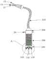
图3是本发明实施例提供的立体内镜组件的主视图;3 is a front view of a stereoscopic endoscope assembly provided by an embodiment of the present invention;
图4是图3中示出的A处的放大剖视图;Fig. 4 is an enlarged cross-sectional view at A shown in Fig. 3;
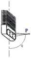
图5-1至图5-3分别是图3中A处的三种镜头倾角的三维示意图;Figures 5-1 to 5-3 are three-dimensional schematic diagrams of three lens inclination angles at A in Figure 3;
图6是本发明实施例提供的立体内镜组件的侧视图;6 is a side view of a stereoscopic endoscope assembly provided by an embodiment of the present invention;
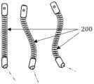
图7是本发明实施例提供的镜身部件的使用状态示意图;7 is a schematic diagram of a use state of a mirror body component provided by an embodiment of the present invention;
图8是本发明实施例提供的内镜支撑组件的结构示意图;8 is a schematic structural diagram of an endoscope support assembly provided by an embodiment of the present invention;
图9是本发明实施例提供的双目立体视觉原理图;9 is a schematic diagram of a binocular stereo vision provided by an embodiment of the present invention;
图10是本发明实施例提供的双目立体显微内镜系统使用原理图。FIG. 10 is a schematic diagram of the use of the binocular stereoscopic endomicroscope system provided by the embodiment of the present invention.
附图标记:Reference number:
1:立体内镜组件;2:双目镜组件;3:第一底座;31:第一转接座;32:第一活动部;4:主杆;41:第一段;42:第二段;51:第二转接座;52:第二活动部;6:支杆;7:第二底座;8:滑槽;9:瞳距调节元件;10:旋转调节元件;11:第一调节件;12:第二调节件;13:目镜视频输出电缆;14:光纤;15:视频输入电缆;16:冷光源;17:图像处理主机;18:显示器;19:内镜固定件;20:内镜固定座;21:柔性调节轴;22:第一紧固件;23:第二紧固件;24:防滑脱耳;25:内镜支架钳脚;26:第三紧固件;27:目标观察点;P:焦点;Q:镜头倾角;1: Stereoscopic endoscope assembly; 2: Binocular lens assembly; 3: The first base; 31: The first adapter seat; 32: The first movable part; 4: The main rod; 41: The first section; 42: The second Section; 51: Second adapter seat; 52: Second movable part; 6: Support rod; 7: Second base; 8: Chute; 9: Interpupillary distance adjustment element; 10: Rotation adjustment element; 11: First Adjusting part; 12: Second adjusting part; 13: Eyepiece video output cable; 14: Optical fiber; 15: Video input cable; 16: Cold light source; 17: Image processing host; 18: Display; 19: Endoscope fixing part; 20 : Endoscope fixing seat; 21: Flexible adjustment shaft; 22: The first fastener; 23: The second fastener; 24: Anti-slip ear; 25: The endoscope bracket clamp foot; 26: The third fastener; 27: target observation point; P: focus; Q: lens inclination;
100:镜头部件;200:镜身部件;300:镜尾部件;400:术者的双眼;110:照明镜头;120:物镜视频镜头;130:电荷耦合元件;310:光电缆;100: lens part; 200: mirror body part; 300: mirror tail part; 400: operator's eyes; 110: illumination lens; 120: objective video lens; 130: charge-coupled element; 310: optical cable;
400:双眼;600:大脑成像。400: binocular; 600: brain imaging.
具体实施方式Detailed ways
下面结合附图和实施例对本发明的实施方式作进一步详细描述。以下实施例用于说明本发明,但不能用来限制本发明的范围。The embodiments of the present invention will be described in further detail below with reference to the accompanying drawings and examples. The following examples are intended to illustrate the present invention, but not to limit the scope of the present invention.
在本发明实施例的描述中,需要说明的是,术语“中心”、“纵向”、“横向”、“上”、“下”、“前”、“后”、“左”、“右”、“竖直”、“水平”、“顶”、“底”、“内”、“外”等指示的方位或位置关系为基于附图所示的方位或位置关系,仅是为了便于描述本发明实施例和简化描述,而不是指示或暗示所指的装置或元件必须具有特定的方位、以特定的方位构造和操作,因此不能理解为对本发明实施例的限制。此外,术语“第一”、“第二”、“第三”仅用于描述目的,而不能理解为指示或暗示相对重要性。In the description of the embodiments of the present invention, it should be noted that the terms "center", "portrait", "horizontal", "top", "bottom", "front", "rear", "left", "right" , "vertical", "horizontal", "top", "bottom", "inside", "outside", etc. indicate the orientation or positional relationship based on the orientation or positional relationship shown in the accompanying drawings, only for the convenience of describing this Inventive embodiments and simplified descriptions are not intended to indicate or imply that the devices or elements referred to must have a particular orientation, be constructed and operate in a particular orientation, and therefore should not be construed as limiting the embodiments of the present invention. Furthermore, the terms "first", "second", and "third" are used for descriptive purposes only and should not be construed to indicate or imply relative importance.
在本发明实施例的描述中,需要说明的是,除非另有明确的规定和限定,术语“相连”、“连接”应做广义理解,例如,可以是固定连接,也可以是可拆卸连接,或一体连接;可以是机械连接,也可以是电连接;可以是直接相连,也可以通过中间媒介间接相连。对于本领域的普通技术人员而言,可以具体情况理解上述术语在本发明实施例中的具体含义。In the description of the embodiments of the present invention, it should be noted that, unless otherwise expressly specified and limited, the terms "connected" and "connected" should be understood in a broad sense, for example, it may be a fixed connection or a detachable connection, Or integral connection; it can be mechanical connection or electrical connection; it can be directly connected or indirectly connected through an intermediate medium. Those of ordinary skill in the art can understand the specific meanings of the above terms in the embodiments of the present invention in specific situations.
在本发明实施例中,除非另有明确的规定和限定,第一特征在第二特征“上”或“下”可以是第一和第二特征直接接触,或第一和第二特征通过中间媒介间接接触。而且,第一特征在第二特征“之上”、“上方”和“上面”可是第一特征在第二特征正上方或斜上方,或仅仅表示第一特征水平高度高于第二特征。第一特征在第二特征“之下”、“下方”和“下面”可以是第一特征在第二特征正下方或斜下方,或仅仅表示第一特征水平高度小于第二特征。In the embodiments of the present invention, unless otherwise expressly specified and limited, the first feature "above" or "under" the second feature may be in direct contact with the first and second features, or the first and second features pass through the middle indirect contact with the media. Also, the first feature being "above", "over" and "above" the second feature may mean that the first feature is directly above or obliquely above the second feature, or simply means that the first feature is level higher than the second feature. The first feature being "below", "below" and "below" the second feature may mean that the first feature is directly below or obliquely below the second feature, or simply means that the first feature has a lower level than the second feature.
在本说明书的描述中,参考术语“一个实施例”、“一些实施例”、“示例”、“具体示例”、或“一些示例”等的描述意指结合该实施例或示例描述的具体特征、结构、材料或者特点包含于本发明实施例的至少一个实施例或示例中。在本说明书中,对上述术语的示意性表述不必须针对的是相同的实施例或示例。而且,描述的具体特征、结构、材料或者特点可以在任一个或多个实施例或示例中以合适的方式结合。此外,在不相互矛盾的情况下,本领域的技术人员可以将本说明书中描述的不同实施例或示例以及不同实施例或示例的特征进行结合和组合。In the description of this specification, description with reference to the terms "one embodiment," "some embodiments," "example," "specific example," or "some examples", etc., mean specific features described in connection with the embodiment or example , structures, materials, or features are included in at least one example or example of embodiments of the present invention. In this specification, schematic representations of the above terms are not necessarily directed to the same embodiment or example. Furthermore, the particular features, structures, materials or characteristics described may be combined in any suitable manner in any one or more embodiments or examples. Furthermore, those skilled in the art may combine and combine the different embodiments or examples described in this specification, as well as the features of the different embodiments or examples, without conflicting each other.
本实施例提供了一种立体内镜组件,能够有效扩大视野范围,并能适应不同手术区域不规则形状的手术要求,以获取具有立体视觉的视频数据,从而使操作更加方便、精细和准确。基于该立体内镜组件,本实施例还提供了一种立体神经内镜,通过更换具有不同镜头倾角的立体内镜组件,从而实现在术中获得更大的视线折射,扩大视野范围,使操作更加方便、精细和准确。进一步的,如图1至图10所示,本发明实施例还提供了一种双目立体显微内镜系统(本发明实施例中简称为系统)。This embodiment provides a stereoscopic endoscope assembly, which can effectively expand the field of view and adapt to the surgical requirements of irregular shapes in different surgical areas, so as to obtain video data with stereoscopic vision, thereby making the operation more convenient, precise and accurate. Based on the stereoscopic endoscope assembly, this embodiment also provides a stereoscopic neuroendoscope. By replacing the stereoscopic endoscope assembly with different lens inclination angles, it is possible to obtain greater refraction of sight during surgery, expand the field of view, and make the operation easier. More convenient, precise and accurate. Further, as shown in FIG. 1 to FIG. 10 , an embodiment of the present invention further provides a binocular stereoscopic endomicroscope system (referred to as a system for short in the embodiment of the present invention).
本实施例所述的系统包括图像处理组件、双目镜组件2以及至少一个可更换的立体内镜组件1。其中,图像处理组件用于将从立体内镜组件1接收到的视频图像数据进行数据处理,并将处理后的视频数据发送给双目镜组件2,从而使得术者(即操作者)在将立体内镜组件1伸入到诸如颅内任意具有不规则通道的手术区域如神经、血管、骨嵴之间时,能够对该手术区域内直线视线受阻挡的病灶位置进行观测,与此同时,借由视频数据的传输和处理,术者可以通过双目镜组件2直接观测到立体视频图像,从而具有立体视觉感,使该系统的操作更加方便、精细和准确,进而使得脑部等细微神经病变手术从原本无法直视的病变区域变为立体可视状态下进行手术,大大提高病变处理的精细程度和手术安全性。The system described in this embodiment includes an image processing assembly, a
可理解的是,本发明实施例中以立体内镜组件1的观测位置为目标观察点27。It is understandable that, in the embodiment of the present invention, the observation position of the stereoscopic endoscope assembly 1 is taken as the
如图1所示,本发明实施例所述的系统中,立体内镜组件1包括镜头部件100和可弯曲的镜身部件200,镜头部件100具有特定的镜头倾角Q。优选的,如图5-1至图5-3所示,可以预先制备多个具有不同镜头倾角Q的立体内镜组件1,并通过更换不同镜头倾角的立体内镜组件1,可以在术中获得更大的视线折射,扩大视野范围。可理解的是,本实施例以扁管状镜身部件200的宽度方向上的对称轴为基准轴,立体内镜组件1的焦点与该基准轴之间的夹角即为立体内镜组件1的镜头倾角Q。As shown in FIG. 1 , in the system according to the embodiment of the present invention, the stereoscopic endoscope assembly 1 includes a
本实施例中,镜头部件100的前端朝向目标观察点27,目标观察点27是指病灶位置中待观察的位置,在对目标观察点27进行观察时将镜头部件100的焦点P与目标观察点27重合即可。镜身部件200连接在镜头部件100的前端,以使立体物内组件1伸入病灶位置时可以根据需要弯曲镜身部件200,从而利用镜身部件200的弯曲状态配合当前立体内镜组件1上镜头部件100的镜头倾角Q,使立体内镜组件1能够对病灶位置进行更全面的观察,有效扩大视野范围,并且能够利用镜身部件200的多角度的弯曲而使得立体内镜组件1适应不同手术区域不规则形状的要求。In this embodiment, the front end of the
本实施例中,镜头部件100与图像处理组件电连接,以便于将立体物内组件1采集到的病灶位置的目标观察点27的视频数据传输至图像采集部件中。In this embodiment, the
本实施例中,双目镜组件2包括并列设置且瞳距可调的一对目镜,以使术者借助双目镜结构产生立体视觉感,使操作更加方便、精细和准确;一对目镜均与图像处理组件电连接,从而能够接收自图像处理组件处理后的立体视频图像。In this embodiment, the
可理解的是,镜身部件200的前端是指镜身部件200伸入手术区域的一端,同理的,镜身部件200的后端是指镜身部件200上远离手术区域的一端。It can be understood that the front end of the
可理解的是,本实施例所述的双目镜组件2利用双目立体视觉原理使术者的双眼400能够通过一对目镜直接观测到立体视频。具体原理如图9和图10所示,该双目立体显微内镜系统利用立体内镜组件1的镜身部件200的可塑变形,配合具有左右双视路的镜头部件100,将双路视频同步传输到图像处理组件中,然后通过图像处理组件对双路视频数据进行处理后,将形成的立体视频传输到双目镜组件2中,从而使术者的双眼400通过双目镜组件2直接观测到视频图像,并在通过大脑成像600产生立体视觉感。It is understandable that the
在一个实施例中,该系统还包括能与手术床连接的支架组件。支架组件的结构如图1和图2所示。双目镜组件2和立体内镜组件1分别可活动的连接在支架组件上。优选双目镜组件2可活动的连接在支架组件的顶部,双目镜组件2的设置高度和倾斜度可根据人体工程学设置,以便于术者借助双目镜组件2观察目标观察点27的视频图像时,术者的姿势更为舒适。立体内镜组件1能固定在支架组件上低于双目镜组件2的位置,以便于术者在通过双目镜组件2观测时,便于调整安放立体内镜组件1的位置。In one embodiment, the system further includes a stand assembly connectable to the surgical bed. The structure of the bracket assembly is shown in Figures 1 and 2. The
在一个实施例中,如图2和图8所示,支架组件包括主杆4、第一底座3、支杆6和第二底座7。主杆4包括位于手术床侧面的第一段41以及位于手术床上方的第二段42,且第一段41与第二段42连接。可选的,第二段42相对于第一段41倾斜设置。立体内镜组件1通过内镜固定座20连接在第二段42上,内镜固定座20能在第二段42上移动,以调整立体内镜组件1的高度和水平位置。第一底座3能连接在手术床的一侧,从而为支架组件提供固定支撑点。第一底座3包括第一转接座31,第一段41插在第一转接座31中,并且第一转接座31能拧紧固定在第一段41上,利用第一转接座31和第一段41的相对位置调整主杆4的整体高度,特别是第二段42的高度;并且,第一段41能够在第一转接座31内旋转,以便调节第二段42上连接的立体内镜组件1和双目镜组件2的水平位置。支杆6的一端通过第二转接座51连接在第二段42上,第二转接座51能沿第二段42的轴向移动以及围绕主杆4旋转,并能通过自转改变支杆6与主杆4的夹角,从而实现主杆4与支杆6之间的三自由度调节。第二底座7通过旋转调节元件10可旋转的连接在支杆6的另一端,第二底座7上固定有双目镜组件2,利用对第二底座7的旋转角度的调整来调节双目镜组件2上两个目镜的水平度。In one embodiment, as shown in FIGS. 2 and 8 , the bracket assembly includes a
在一个实施例中,第一底座3包括第一转接座31、第一活动部32和第一调节件11。第一活动部32与手术床相连接。第一转接座31的径向上设有通孔,主杆4的第一段41可活动的插在通孔内,从而可以调整主杆4的高度。第一转接座31和第一活动部32之间通过端面连接,并且彼此能相对转动,以便于调解主杆4与手术床之间的角度,以实现主杆4的多自由度调节。第一转接座31和第一活动部32之间的端面上设有齿槽,在第一转接座31和第一活动部32之间相对紧固时,齿槽可以增加摩擦,从而将第一转接座31和第一活动部32之间更可靠的固定,防止第一转接座31和第一活动部32之间发生转动滑脱。第一调节件11依次穿过第一转接座31和第一活动部32,在第一调节件11处于拧紧状态下,第一段41压紧固定在第一转接座31内,并且第一调节件11将第一活动部32顶紧固定在手术床的一侧,从而将主杆4、第一底座3和手术床三者之间的位置可靠固定。In one embodiment, the first base 3 includes a
在一个实施例中,第二转接座51通过第二活动部52与支杆6连接。具体为:第二转接座51和第二活动部52沿各自的径向分别设有通孔,主杆4的第二段42和支杆6分别对应的插在第二转接座51和第二活动部52的通孔内,以便于调节主杆4和支杆6之间的相对位置和高度。第二转接座51和第二活动部52之间通过端面连接,并且彼此能相对转动,以便于调解主杆4与支杆6之间的夹角,以实现支杆6的多自由度调节。第二转接座51和第二活动部52之间的端面上设有齿槽,齿槽可以增加摩擦,从而将第二转接座51和第二活动部52之间更可靠的固定,防止第二转接座51和第二活动部52之间发生转动滑脱。第二转接座51上远离第二活动部52的端面上连接有第二调节件12,第二调节件12依次穿过第二转接座51和第二活动部52,在第二调节件12处于拧紧状态下,第二段42和支杆6分别能压紧固定在第二转接座51和第二活动部52内,从而将主杆4与支杆6之间的位置、高度和夹角都可靠固定。In one embodiment, the
可理解的是,第一调节件11和第二调节件12可选用带有旋转把手的调节螺杆。It is understandable that, the first adjusting
在一个实施例中,如图2所示,双目镜组件2包括上述的一对目镜以及瞳距调节元件9和滑槽8。一对目镜结构相同,且分别通过目镜视频输出电缆13与图像处理组件电连接。滑槽8设在上述的第二底座7上背向支杆6的端面上,一对目镜分别可滑动的嵌设在滑槽8内;瞳距调节元件9连接在滑槽8的一侧,瞳距调节元件9用于驱动一对目镜分别沿滑槽8滑动地聚集或分离,从而调整这一对目镜的瞳距。In one embodiment, as shown in FIG. 2 , the
可理解的是,瞳距是指上述的一对目镜的镜筒轴线之间的距离。旋转调节元件10和瞳距调节元件9优选为调节螺杆或调节螺丝。It can be understood that the interpupillary distance refers to the distance between the above-mentioned lens barrel axes of the pair of eyepieces. The
在一个实施例中,如图1、图3、图4和图6所示,立体内镜组件1的镜头部件100包括两个物镜视频镜头120。进一步的,镜头部件100还包括照明镜头110。In one embodiment, as shown in FIGS. 1 , 3 , 4 and 6 , the
在一个具体实施例中,照明镜头110的两侧分别设有一物镜视频镜头120,两个物镜视频镜头120的焦点轴都聚焦在焦点P。应当明确的是,两个物镜视频镜头120分别固定在镜头部件100的本体部分上,由于不同立体内镜组件1的镜头部件100的本体部分可以相对于镜身部件200的宽度方向上的对称轴有不同角度的倾斜角度,从而使得不同立体内镜组件1的镜头部件100的镜头倾角Q各不相同,但所有的立体内镜组件1的镜头部件100的两个物镜视频镜头120都是固定在当前镜头部件100的本体部分上的,故而不论当前使用的立体内镜组件1的镜头部件100的镜头倾角Q为多少角度,两个物镜视频镜头120的焦点P都始终位于镜头部件100的前方,并且两个物镜视频镜头120的焦点轴的夹角始终保持不变,即如图5-1至图5-3所示。In a specific embodiment, an
可理解的是,为了获取最佳的拍摄光源,优选照明镜头110的焦点轴与两个物镜视频镜头120的焦点轴都聚焦在焦点P。It can be understood that, in order to obtain the best shooting light source, it is preferable that the focal axis of the
需要说明的是,两个物镜视频镜头120可以安装在镜头部件100的本体部分上的任意位置。例如图5-1所示,照明镜头110和两个物镜视频镜头120同时固定在镜头部件100的本体部分的底部,以使焦点P落在基准轴上,即当前的立体内镜组件1的镜头倾角Q为0°。又例如图5-3所示,照明镜头110和两个物镜视频镜头120同时固定在镜头部件100的本体部分的侧面,此时两个物镜视频镜头120的焦点轴的夹角不发生改变,但焦点P与基准轴之间形成了90°的夹角,即当前的立体内镜组件1的镜头倾角Q为90°。再例如图5-2所示,照明镜头110和两个物镜视频镜头120同时固定在镜头部件100的本体部分的底部,并且镜头部件100的本体部分相对于基准轴弯折,此时两个物镜视频镜头120的焦点轴的夹角不发生改变,但焦点P与基准轴之间形成了大于0°并小于90°的夹角,即当前的立体内镜组件1的镜头倾角Q大于0°并小于90°。本实施例所述镜头倾角Q的取值范围优选为0°≤Q≤90°,并且进一步优选预先制备镜头倾角Q为0°、30°、45°、70°以及90°的立体镜头组件1以便更换使用。It should be noted that, the two
在一个实施例中,立体内镜组件1镜身部件200能在纵向上弯曲塑形,从而变成合适的曲度置于术区适宜部位,如图7所示。In one embodiment, the
可理解的是,本发明实施例所述的立体内镜组件1中,立体内镜组件1的轴向是指沿镜头部件100、镜身部件200和光电缆310的全长方向,立体内镜组件1的横向是指镜身部件200的金属波纹扁管的长径方向,而立体内镜组件1的纵向是指镜身部件200的金属波纹扁管的短径方向。It can be understood that, in the stereoscopic endoscope assembly 1 according to the embodiment of the present invention, the axial direction of the stereoscopic endoscope assembly 1 refers to the direction along the entire length of the
如图4所示,两个物镜视频镜头120上分别连接有电荷耦合元件130,以利用电荷耦合元件130(简称CCD元件)通过两个物镜视频镜头120分别获取两路视频数据。As shown in FIG. 4 , charge-coupled
在一个实施例中,如图3、图6和图8所示,立体内镜组件1还包括镜尾部件300。镜尾部件300连接在镜身部件200上远离镜头部件100的一端,以便为内镜固定件19提供夹持固定的区域。内镜固定件19包括一对内镜支架钳脚25、以及第三紧固件26,第三紧固件26穿过一对内镜支架钳脚25的一端,以驱动一对内镜支架钳脚25的另一端能相对的夹持在镜尾部件300的两侧,一对内镜支架钳脚25上穿有第三紧固件26的端部与柔性调节轴21连接。镜尾部件300的两侧分别设有防滑脱耳24,防滑脱耳24能防止立体内镜组件1从内镜固定件19的钳脚中滑脱。内镜固定座20通过柔性调节轴21与内镜固定件19连接。In one embodiment, as shown in FIGS. 3 , 6 and 8 , the stereoscopic endoscope assembly 1 further includes a
本实施例所述的内镜固定件19通过两个L形的内镜支架钳脚25钳夹在立体内镜组件1的镜尾部件300上。具体为:镜身部件200优选为波纹扁管,在纵向上能在一定程度上弯曲塑形,而在横向上不可弯曲;两个L形的内镜支架钳脚25的一端分开钳夹在镜尾部件300的较宽的两个表面上,以使内镜固定件19能够为镜身部件200提供可靠的固定支撑。两个L形的内镜支架钳脚25的另一端彼此连接在柔性调节轴21的一端上,并且这两个L形的内镜支架钳脚25与柔性调节轴21连接的一端通过第三紧固件26锁紧以提高内镜支架钳脚25对镜尾部件300的夹持力。一侧防滑脱耳24穿入内镜支架钳脚25的小孔内通过第三紧固件26使内镜固定件19锁紧固定于镜尾部件300上。The
在一个实施例中,内镜固定座20包括固定座本体、第一紧固件22和第二紧固件23。如图8所示,第一紧固件22和第二紧固件23分别设在固定座本体上。其中,第一紧固件22与连接在固定座本体一端的柔性调节轴21连接,用于驱动柔性调节轴21在锁固状态(即固定不可变状态)和可活动状态(即松弛状态)之间切换。柔性调节轴21在松驰状态时可自由弯曲,而在拧紧第一紧固件22时,柔性调节轴21即处于固定不可变状态。通过第一紧固件22控制柔性调节轴21的状态变化,从而能够根据需要而改变内镜固定件19的位置,并且将内镜固定件19固定停留在任一位置上。固定座本体内设有供主杆4的第二段42穿过的夹持腔,第二紧固件23能穿过固定座本体并顶紧在第二段42上,以使固定座本体能固定在第二段42上,从而便于改变内镜固定座20在主杆4上的位置和高度。In one embodiment, the
可理解的是,第一紧固件22、第二紧固件23和第三紧固件26优选为紧固螺钉,当然也可以采用其它紧固件,在此不做具体限定。It is understandable that the
在一个实施例中,如图3和图4所示,立体内镜组件1还包括光电缆310。光电缆310包括光纤14和视频输入电缆15。照明镜头110通过光纤14与图像处理组件电连接,两个物镜视频镜头120分别或共同通过视频输入电缆15与图像处理组件电连接,光纤14和视频输入电缆15并列的嵌设在镜身部件200的内腔中。In one embodiment, as shown in FIGS. 3 and 4 , the stereoscopic endoscope assembly 1 further includes an
在一个实施例中,图像处理组件包括冷光源16、图像处理主机17和显示器18。冷光源16和图像处理主机17分别与立体内镜组件1电连接,图像处理主机17还与双目镜组件2电连接,显示器18与图像处理主机17电连接。In one embodiment, the image processing component includes a cold
在一个具体实施例中,如图1所示,照明镜头110通过光纤14与冷光源16电连接,两个物镜视频镜头120分别通过两条视频输入电缆15与图像处理主机17电连接,图像处理主机17还通过目镜视频输出电缆13与双目镜组件2电连接。可理解的是,可以两个物镜视频镜头120共同连在同一条视频输入电缆15上,以实现电缆合并,优化线路。In a specific embodiment, as shown in FIG. 1 , the
可理解的是,图1中示例出了一种图像处理主机17的实体结构示意图。如图2所示,该图像处理主机17可以包括:处理器(processor、通信接口(Communications Interface、存储器(memory和通信总线,其中,处理器、通信接口、存储器通过通信总线完成相互间的通信。处理器可以调用存储器中的逻辑指令,以实现图像处理工作,即如本实施例所述的将双路视频数据处理为立体图像和/或立体视频影像。It is understandable that FIG. 1 illustrates a schematic diagram of the physical structure of an
在一个具体实施例中,镜头部件100的两个物镜视频镜头120的外部包裹有金属外层,且在两个物镜视频镜头120之间夹装有至少一个照明镜头110。所有的照明镜头110在横向和纵向均与两个物镜视频镜头120的焦点P的方向一致,而两个物镜视频镜头120聚焦的焦点P即为目标观察点27。如图4所示,镜身部件200的外壁设置为金属波纹扁管,在金属波纹扁管的横截面的左右两侧为两条视频输入电缆15,两条视频输入电缆15的中间为与冷光源16连接的光纤14,镜身部件200的波纹结构在纵向上可在一定程度上的弯曲塑形,如图7所示,以适应不同形状规格的手术区。镜尾部件300为与光电缆310衔接的硬质金属结构,并在镜尾部件300的两侧装配有防滑脱耳24,用于插入内镜固定件19钳脚25侧孔内。光电缆310的外表面被柔软外包裹层包裹,以便在术中自由放置而不影响镜头固定。光电缆310的尾部实现光缆与电缆分离,即分别通过接口端衔接光纤14与冷光源16的连接、以及两条视频输入电缆15分别与图像处理主机17的视频处理单元左右输入口的电连接。双路视频数据的输入信号经图像处理主机17后分别输出到双目镜组件2中,以使术者通过双目镜组件2的立体视觉状态下感受到立体视觉感,从而进行精细手术操作。In a specific embodiment, the outside of the two
在操作该系统进行手术前,调节主杆4在手术床的前后位置和高低位置,调整转接座5在主杆4上的左右位置,以及调节支杆6的长短位置和上下角度,从而使双目镜组件2处于一个适合术者观测的高度。调节完毕后拧紧第一调节件11和第二调节件12,使整个支架组件处于固定状态。通过旋转瞳距调节元件9使一对目镜沿滑槽8相对移动,从而使一对目镜的瞳距与术者相符。通过调节旋转调节元件10使第二底座7旋转,从而使双目镜组件2能更好的与术者的操作姿势一致。Before operating the system for surgery, adjust the front and rear positions and height positions of the
在操作该系统进行手术过程中,将选定好的具有特定的倾角Q的立体内镜组件1按上述连接关系安装在系统中,并将冷光源16通过光纤14传输到照明镜头110上,通过改变镜身部件200的弯曲度可以改变立体内镜组件1的观测角度,扩大立体内镜组件1在手术区域中的视野范围,从而可以获取到显微镜直线光线无法照到的盲区的视频数据,如图7以及图5-1至图5-3所示。During the operation of the system, the selected stereoscopic endoscope assembly 1 with a specific inclination angle Q is installed in the system according to the above-mentioned connection relationship, and the cold
双侧视频物镜镜头分别通过CCD元件采集图像,并经由两条视频输入电缆15向图像处理主机17中输入双路视频数据。图像处理主机17将处理后的立体视频经两条目镜视频输出电缆13传送到一对目镜中,以使得术者能通过双目镜组件2获得具有立体视觉感的立体视频,从而在立体视觉状态下进行手术操作。与此同时,图像处理主机17还能将立体视频信号另输出到显示器18中,从而使助手或参观者通过佩戴偏振光眼镜共享立体视频影像。The double-side video objective lens collects images through CCD elements respectively, and inputs dual-channel video data to the
以上实施方式仅用于说明本发明,而非对本发明的限制。尽管参照实施例对本发明进行了详细说明,本领域的普通技术人员应当理解,对本发明的技术方案进行各种组合、修改或者等同替换,都不脱离本发明技术方案的精神和范围,均应涵盖在本发明的权利要求范围中。The above embodiments are only used to illustrate the present invention, but not to limit the present invention. Although the present invention has been described in detail with reference to the embodiments, those of ordinary skill in the art should understand that various combinations, modifications or equivalent replacements to the technical solutions of the present invention do not depart from the spirit and scope of the technical solutions of the present invention, and should cover within the scope of the claims of the present invention.
Claims (10)
Translated fromChinesePriority Applications (1)
| Application Number | Priority Date | Filing Date | Title |
|---|---|---|---|
| CN202010266125.4ACN111419158B (en) | 2020-04-07 | 2020-04-07 | Stereoscopic endoscope assembly and stereoscopic nerve endoscope |
Applications Claiming Priority (1)
| Application Number | Priority Date | Filing Date | Title |
|---|---|---|---|
| CN202010266125.4ACN111419158B (en) | 2020-04-07 | 2020-04-07 | Stereoscopic endoscope assembly and stereoscopic nerve endoscope |
Publications (2)
| Publication Number | Publication Date |
|---|---|
| CN111419158Atrue CN111419158A (en) | 2020-07-17 |
| CN111419158B CN111419158B (en) | 2023-03-21 |
Family
ID=71552266
Family Applications (1)
| Application Number | Title | Priority Date | Filing Date |
|---|---|---|---|
| CN202010266125.4AActiveCN111419158B (en) | 2020-04-07 | 2020-04-07 | Stereoscopic endoscope assembly and stereoscopic nerve endoscope |
Country Status (1)
| Country | Link |
|---|---|
| CN (1) | CN111419158B (en) |
Cited By (1)
| Publication number | Priority date | Publication date | Assignee | Title |
|---|---|---|---|---|
| CN114849021A (en)* | 2022-05-09 | 2022-08-05 | 精微致远医疗科技(武汉)有限公司 | Visual intubation device and using method thereof |
Citations (4)
| Publication number | Priority date | Publication date | Assignee | Title |
|---|---|---|---|---|
| US4941457A (en)* | 1989-08-17 | 1990-07-17 | Olympus Optical Co., Ltd. | Endoscope using an optical guide twisted on the tip side to have the visual field direction and curvature axis coincide with each other |
| US5689365A (en)* | 1994-09-13 | 1997-11-18 | Olympus Optical Co., Ltd | Stereoscopic-vision endoscope |
| CN104799803A (en)* | 2015-05-14 | 2015-07-29 | 珠海视新医用科技有限公司 | Dual-lens distal end part structure for endoscope |
| WO2019211456A1 (en)* | 2018-05-03 | 2019-11-07 | Konstantin Bob | Endoscope deflection using a distal folding mechanism |
- 2020
- 2020-04-07CNCN202010266125.4Apatent/CN111419158B/enactiveActive
Patent Citations (4)
| Publication number | Priority date | Publication date | Assignee | Title |
|---|---|---|---|---|
| US4941457A (en)* | 1989-08-17 | 1990-07-17 | Olympus Optical Co., Ltd. | Endoscope using an optical guide twisted on the tip side to have the visual field direction and curvature axis coincide with each other |
| US5689365A (en)* | 1994-09-13 | 1997-11-18 | Olympus Optical Co., Ltd | Stereoscopic-vision endoscope |
| CN104799803A (en)* | 2015-05-14 | 2015-07-29 | 珠海视新医用科技有限公司 | Dual-lens distal end part structure for endoscope |
| WO2019211456A1 (en)* | 2018-05-03 | 2019-11-07 | Konstantin Bob | Endoscope deflection using a distal folding mechanism |
Cited By (1)
| Publication number | Priority date | Publication date | Assignee | Title |
|---|---|---|---|---|
| CN114849021A (en)* | 2022-05-09 | 2022-08-05 | 精微致远医疗科技(武汉)有限公司 | Visual intubation device and using method thereof |
Also Published As
| Publication number | Publication date |
|---|---|
| CN111419158B (en) | 2023-03-21 |
Similar Documents
| Publication | Publication Date | Title |
|---|---|---|
| US11336804B2 (en) | Stereoscopic visualization camera and integrated robotics platform | |
| AU2019261643B2 (en) | Stereoscopic visualization camera and integrated robotics platform | |
| US10646212B2 (en) | Devices and method for access and visualization for lumbar interbody fusion (LIF) | |
| EP2932886B1 (en) | A video system for viewing an object on a body | |
| US7768701B2 (en) | Three-dimensional medical imaging apparatus | |
| JP3032214B2 (en) | Surgical microscope | |
| JP2007503277A (en) | System, apparatus and method for observing hard-to-see parts of a cavity | |
| KR101476820B1 (en) | 3D video microscope | |
| WO1995010218A1 (en) | Stereoscopic percutaneous visualization system | |
| CN112022056B (en) | Imaging system and observation method | |
| KR20050011468A (en) | Flexible dual endoscopy for laproscope | |
| CN111419156B (en) | Binocular stereo microscope endoscope system | |
| CN101889853B (en) | Three-dimensional endoscope system capable of rotating freely for angles | |
| US4702571A (en) | Instrument for visual observation utilizing fiber optics | |
| US4834518A (en) | Instrument for visual observation utilizing fiber optics | |
| JP4383188B2 (en) | Stereoscopic observation system | |
| CA2776181A1 (en) | Twin camera endoscope | |
| CN111419158B (en) | Stereoscopic endoscope assembly and stereoscopic nerve endoscope | |
| CN109498162B (en) | Main operation table for improving immersion sense and surgical robot | |
| CN211460506U (en) | Main operating platform for improving immersion feeling and surgical robot | |
| EP3522769B1 (en) | An endomicroscopic device | |
| CN109498164B (en) | Main operation table with ocular lens and surgical robot | |
| EP4328648A1 (en) | Digital microscope for medical procedure | |
| US20250255465A1 (en) | Endoscopy imaging system including in-line dual camera 3d endoscopy cannula assembly | |
| CN109498163B (en) | Main operation table and surgical robot |
Legal Events
| Date | Code | Title | Description |
|---|---|---|---|
| PB01 | Publication | ||
| PB01 | Publication | ||
| SE01 | Entry into force of request for substantive examination | ||
| SE01 | Entry into force of request for substantive examination | ||
| GR01 | Patent grant | ||
| GR01 | Patent grant |