CN111415496B - An intelligent note control method based on image recognition - Google Patents
An intelligent note control method based on image recognitionDownload PDFInfo
- Publication number
- CN111415496B CN111415496BCN202010246077.2ACN202010246077ACN111415496BCN 111415496 BCN111415496 BCN 111415496BCN 202010246077 ACN202010246077 ACN 202010246077ACN 111415496 BCN111415496 BCN 111415496B
- Authority
- CN
- China
- Prior art keywords
- drawing pin
- conductive adhesive
- positive
- diameter section
- image
- Prior art date
- Legal status (The legal status is an assumption and is not a legal conclusion. Google has not performed a legal analysis and makes no representation as to the accuracy of the status listed.)
- Active
Links
Images


Classifications
- G—PHYSICS
- G08—SIGNALLING
- G08B—SIGNALLING OR CALLING SYSTEMS; ORDER TELEGRAPHS; ALARM SYSTEMS
- G08B21/00—Alarms responsive to a single specified undesired or abnormal condition and not otherwise provided for
- G08B21/18—Status alarms
- G08B21/24—Reminder alarms, e.g. anti-loss alarms
- B—PERFORMING OPERATIONS; TRANSPORTING
- B42—BOOKBINDING; ALBUMS; FILES; SPECIAL PRINTED MATTER
- B42D—BOOKS; BOOK COVERS; LOOSE LEAVES; PRINTED MATTER CHARACTERISED BY IDENTIFICATION OR SECURITY FEATURES; PRINTED MATTER OF SPECIAL FORMAT OR STYLE NOT OTHERWISE PROVIDED FOR; DEVICES FOR USE THEREWITH AND NOT OTHERWISE PROVIDED FOR; MOVABLE-STRIP WRITING OR READING APPARATUS
- B42D5/00—Sheets united without binding to form pads or blocks
- F—MECHANICAL ENGINEERING; LIGHTING; HEATING; WEAPONS; BLASTING
- F21—LIGHTING
- F21V—FUNCTIONAL FEATURES OR DETAILS OF LIGHTING DEVICES OR SYSTEMS THEREOF; STRUCTURAL COMBINATIONS OF LIGHTING DEVICES WITH OTHER ARTICLES, NOT OTHERWISE PROVIDED FOR
- F21V33/00—Structural combinations of lighting devices with other articles, not otherwise provided for
- F21V33/0004—Personal or domestic articles
- F21V33/0048—Office articles, e.g. bookmarks, desk lamps with drawers, stands for books or music scores
- G—PHYSICS
- G06—COMPUTING OR CALCULATING; COUNTING
- G06T—IMAGE DATA PROCESSING OR GENERATION, IN GENERAL
- G06T5/00—Image enhancement or restoration
- G06T5/20—Image enhancement or restoration using local operators
- G06T5/30—Erosion or dilatation, e.g. thinning
- G—PHYSICS
- G06—COMPUTING OR CALCULATING; COUNTING
- G06T—IMAGE DATA PROCESSING OR GENERATION, IN GENERAL
- G06T5/00—Image enhancement or restoration
- G06T5/80—Geometric correction
- G—PHYSICS
- G06—COMPUTING OR CALCULATING; COUNTING
- G06V—IMAGE OR VIDEO RECOGNITION OR UNDERSTANDING
- G06V10/00—Arrangements for image or video recognition or understanding
- G06V10/20—Image preprocessing
- G06V10/25—Determination of region of interest [ROI] or a volume of interest [VOI]
- G—PHYSICS
- G06—COMPUTING OR CALCULATING; COUNTING
- G06V—IMAGE OR VIDEO RECOGNITION OR UNDERSTANDING
- G06V10/00—Arrangements for image or video recognition or understanding
- G06V10/40—Extraction of image or video features
- G06V10/56—Extraction of image or video features relating to colour
Landscapes
- Engineering & Computer Science (AREA)
- Physics & Mathematics (AREA)
- General Physics & Mathematics (AREA)
- Theoretical Computer Science (AREA)
- Multimedia (AREA)
- General Engineering & Computer Science (AREA)
- Business, Economics & Management (AREA)
- Emergency Management (AREA)
- Telephone Set Structure (AREA)
- Push-Button Switches (AREA)
Abstract
Description
Translated fromChinese技术领域technical field
本发明涉及办公用品技术领域,特别涉及一种基于图像识别的智能便签控制方法。The invention relates to the technical field of office supplies, in particular to an image recognition-based intelligent note control method.
背景技术Background technique
便签,是一种小型的便于携带的纸张,有的一面有黏性,多是黄色的,为了迎合年轻人的喜好,也出现了其他鲜艳的颜色,用来随时记下一些内容,如写便条,电话号码等。一般用于办公室、电话记录。在你会忘记做某事时,就可以写在上面贴在自己会看见的地方,就能重新回想起这件事。也可以用于留言,告知他人。便签板就是一种专门用于贴便签的产品,一般多为平板状,由木质材料制成,常带有边框。在使用时,用户写好的便签多通过工字钉固定在便签板上。便签板通常放在办公室内,要么通过支架放置在桌面或地面上,要么固定安装在墙面上,目前市面上的便签板多为普通的板体,工字钉也是普通的钉子,用户常常需要主动去查看自己所记的便签,这样当用户比较忙碌的时候,常常会错过标签上记录的事务,所以急需一种可以自动进行提醒的便签系统。这种便签系统中,需要可靠的获取图钉位置或设定每个图钉的提醒时间,最常见的做法是通过按键和显示屏进行设置,但是这种设置方式比较单一,设置的时候也不够方便。Post-it notes are small and easy-to-carry papers, some sticky on one side, and mostly yellow. In order to cater to the preferences of young people, other bright colors have also appeared, which are used to jot down some content at any time, such as writing notes. , phone number, etc. Generally used for office, telephone records. When you forget to do something, you can write it on it and stick it where you can see it, and you can recall it. It can also be used to leave a message to inform others. A note board is a product specially used for sticking notes. Generally, it is mostly flat, made of wood material, and often has a frame. In use, the sticky notes written by the user are mostly fixed on the sticky note board by means of I-nails. The note board is usually placed in the office, either on the desktop or the ground through a bracket, or fixed on the wall. At present, the note boards on the market are mostly ordinary boards, and the I-nails are also ordinary nails. Users often need Take the initiative to check the notes that you have written down, so that when users are busy, they often miss the transactions recorded on the label, so a note system that can automatically remind is urgently needed. In this sticky note system, it is necessary to reliably obtain the position of the pushpin or set the reminder time of each pushpin. The most common method is to set it through the buttons and the display screen, but this setting method is relatively simple, and the setting is not convenient enough.
发明内容SUMMARY OF THE INVENTION
本发明的首要目的在于提供一种基于图像识别的智能便签控制方法,能够快速方便的获取图钉位置和设定图钉提醒时间。The primary purpose of the present invention is to provide an intelligent memo control method based on image recognition, which can quickly and conveniently obtain the position of the pushpin and set the reminder time of the pushpin.
为实现以上目的,本发明采用的技术方案为:一种基于图像识别的智能便签控制方法,包括如下步骤:A、通过图钉将便签固定到插板上,图钉内的LED灯珠通过插板内布置的纵横交错的线路以及多选开关连接电源正负极;B、移动终端拍摄插板正面图像并对图像进行处理得到图钉的位置信息;C、用户在移动终端上为每个图钉设置提醒时间,任一图钉到达提醒时间时移动终端发送图钉位置信息给控制模块;D、控制模块根据图钉的位置信息驱动多选开关动作使得图钉所在位置的线路与电源正负极连通并点亮该图钉内的LED灯珠。In order to achieve the above purpose, the technical solution adopted in the present invention is: an image recognition-based intelligent memo control method, comprising the following steps: A. Fix the memo to the insert board through a pushpin, and the LED lamp beads in the pushpin pass through the inside of the insert board. The arranged criss-crossed lines and the multi-select switch are connected to the positive and negative poles of the power supply; B. The mobile terminal captures the front image of the plugboard and processes the image to obtain the position information of the pushpin; C. The user sets the reminder time for each pushpin on the mobile terminal , when any pushpin reaches the reminder time, the mobile terminal sends the position information of the pushpin to the control module; D. The control module drives the multi-select switch action according to the position information of the pushpin, so that the line where the pushpin is located is connected with the positive and negative poles of the power supply and lights the inside of the pushpin LED lamp beads.
与现有技术相比,本发明存在以下技术效果:这里通过移动终端拍摄插板上的图像,并自动对图像进行识别得到图钉的位置信息,然后可以在移动终端上对每个图钉设置提醒时间,等到提醒时间到了就会发信号给控制模块,让控制模块点亮相应图钉内的LED灯珠,该操作流程使用起来非常方便,操作便利。Compared with the prior art, the present invention has the following technical effects: the image on the board is photographed by the mobile terminal, and the position information of the pushpin is obtained by automatically recognizing the image, and then a reminder time can be set for each pushpin on the mobile terminal , when the reminder time is up, it will send a signal to the control module to let the control module light up the LED lamp beads in the corresponding pushpin. This operation process is very convenient to use and easy to operate.
附图说明Description of drawings
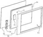
图1是实施例一的爆炸结构示意图;Fig. 1 is the exploded structure schematic diagram of embodiment one;
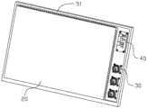
图2是实施例一的立体结构示意图,其中未示出背板;FIG. 2 is a schematic three-dimensional structure diagram of Embodiment 1, wherein the backplane is not shown;
图3是实施例二的爆炸结构示意图;Fig. 3 is the exploded structure schematic diagram of embodiment two;
图4是实施例二的立体结构示意图,其中未示出背板;Fig. 4 is the three-dimensional structure schematic diagram of the second embodiment, wherein the back plate is not shown;
图5是插板的爆炸结构示意图;Fig. 5 is the exploded structure schematic diagram of the plug-in board;
图6是图钉的爆炸结构示意图;Fig. 6 is the exploded structure schematic diagram of pushpin;
图7是图钉的剖视图;Figure 7 is a cross-sectional view of a pushpin;
图8是实施例一中旋转式多选开关的立体结构示意图;8 is a schematic three-dimensional structure diagram of the rotary multi-select switch in the first embodiment;
图9是实施例一中旋转式多选开关的爆炸结构示意图;Fig. 9 is the exploded structure schematic diagram of the rotary multi-select switch in the first embodiment;
图10是实施例一中旋转式多选开关的剖视图;10 is a cross-sectional view of the rotary multi-select switch in the first embodiment;
图11是实施例二中直线式多选开关的立体结构示意图。FIG. 11 is a schematic three-dimensional structure diagram of the linear multi-select switch in the second embodiment.
具体实施方式Detailed ways
下面结合图1至图11,对本发明做进一步详细叙述。The present invention will be described in further detail below with reference to FIGS. 1 to 11 .
参阅图1-图4,一种基于图像识别的智能便签控制方法,包括如下步骤:A、通过图钉10将便签固定到插板20上,图钉10内的LED灯珠15通过插板20内布置的纵横交错的线路以及多选开关30连接电源正负极;B、移动终端拍摄插板20正面图像并对图像进行处理得到图钉10的位置信息;C、用户在移动终端上为每个图钉10设置提醒时间,任一图钉10到达提醒时间时移动终端发送图钉10位置信息给控制模块40;D、控制模块40根据图钉10的位置信息驱动多选开关30动作使得图钉10所在位置的线路与电源正负极连通并点亮该图钉10内的LED灯珠15。这里通过移动终端拍摄插板20上的图像,并自动对图像进行识别得到图钉10的位置信息,然后可以在移动终端上对每个图钉10设置提醒时间,等到提醒时间到了移动终端就会发信号给控制模块40,让控制模块40点亮相应图钉10内的LED灯珠15,该操作流程使用起来非常方便,操作便利。Referring to FIG. 1 to FIG. 4 , an image recognition-based intelligent memo control method includes the following steps: A. The memo is fixed to the
参阅图5,插板20的结构有很多种,本发明中优选地,所述的插板20包括底座21,底座21呈方盒状,底座21自下而上依次布置有横向导电胶条22、纵向导电胶条23以及泡绵层24,泡绵层24一般由高密度海绵材料制成,方便插入图钉10且在图钉10拔出后不会留下孔洞。多个横向导电胶条22相邻布置,多个纵向导电胶条23相邻布置,横向导电胶条22和纵向导电胶条23的彼此垂直,这样横向导电胶条22和纵向导电胶条23就形成了纵横交错的线路,每个横向导电胶条22和纵向导电胶条23都设置有绝缘外层221,避免相邻的两个导电胶条导通,底座21相邻的两边外周壁上设置有导电钉25,导电钉25插入底座21的侧边内并与横向导电胶条22或纵向导电胶条23导通。导电钉25的设置,是为了方便横向导电胶条22和纵向导电胶条23与其他电路连接,比如本发明中,导电胶条和多选开关30连接时,只需要通过导线连接导电钉25和多选开关30即可,图2和图4中并未示出导线,因为线路太多,都表现出来会影响其他部件的显示。所述的步骤A中,横向导电胶条22和纵向导电胶条23即构成纵横交错的线路,电源正、负极分别通过多选开关30连接横向导电胶条22、纵向导电胶条23,图钉10和泡绵层24颜色相异,这样更有利于图像中图钉10的识别。Referring to FIG. 5, there are many structures of the plug-in
参阅图6和图7,图钉10从插板20中得电也有很多种结构可以实现,故这里优选地,所述的图钉10包括内芯11、绝缘芯套12、外芯13、图钉外壳14以及LED灯珠15,内芯11和外芯13均为导电材料制成;所述的内芯11包括第一大直径段111和第一小直径段112;绝缘芯套12套设在内芯11的第一小直径段112上,绝缘芯套12包括第二大直径段121和第二小直径段122;外芯13套设在第二小直径段122上,外芯13包括第三大直径段131和第三小直径段132;LED灯珠15的其中一个引脚插置于绝缘芯套12的第二小直径段122内并与内芯11的第一小直径段112相连,LED灯珠15的另一个引脚与外芯13的第三大直径段131相连;第一大直径段111、第二大直径段121以及第三小直径段132外径相等且共同构成图钉10的钉头;图钉外壳14套设在第三大直径段131和LED灯珠15的外侧;泡绵层24为白色,图钉外壳14底部为黑色,这样设置有利于图像中图钉10的识别,图钉外壳14顶部由透明材料制成或开设有微孔供LED灯珠15的光线射出,外芯13的第三小直径段132的长度大于泡绵层24的厚度,图钉10插入插板20时绝缘芯套12位于横向导电胶条22和纵向导电胶条23之间。通过这种结构,让图钉10更紧凑,在装配的时候,首先拿出外芯13,然后将绝缘芯套12插入外芯13中,再然后将内芯11插入绝缘芯套12中,最后把LED灯珠15的两个引脚分别点上焊锡,分别与外芯13和内芯11相连,本发明中,外芯13的第三大直径段131上设置有沉孔,LED灯珠15的一个引脚点上焊锡后直接插入其中冷却后即固定,内芯11的第一小直径段112的长度小于绝缘芯套12的长度,这样,LED灯珠15的另一个引脚点上焊锡后直接插入绝缘芯套12中即可与内芯11固定连接。Referring to FIG. 6 and FIG. 7 , there are many structures for the
图像识别算法有很多,本发明中需要从白色的泡绵层24上识别出黑色的图钉相对来说较为容易,具体地,所述的步骤B中,按如下步骤获取图钉10位置信息:B1、移动终端拍摄插板20正面图像得到原始RGB图像,尽量拍摄正面图像,更有利于图钉10的识别;B2、对RGB图像进行梯形校正,考虑到拍摄时因角度问题,插板20周边轮廓肯定会发生畸变,不会是一个长方形,因此这里通过算法进行梯形校正,校正后的图像中插板20的轮廓为方形,有利于下一步处理;B3、根据设定好的阈值对校正后的RGB图像进行二值化处理得到黑白图像,黑白图像中黑色区域为图钉10、白色区域为背景,由于泡绵层24和图钉10的颜色有显著差异,因此将图像中的图钉10区域识别出来,只要通过阈值判断即可实现;B4、根据黑白图像中黑色区域面积大小筛选出真实图钉区域,这个步骤主要是用于去除噪点,一般通过膨胀和腐蚀处理后,再去掉面积较小的区域即可;B5、求解每个真实图钉区域的最小外接矩形并得到最小外接矩形的中心位置;B6、根据横向导电胶条22和纵向导电胶条23的个数将插板20分割成方形网格,获取每个真实图钉区域中心位置所处的网格编号。横向导电胶条22可以从上到下按数字进行编号,纵向导电胶条23可以从左到右按数字进行编号,这样就可以用两个数字代表图钉10的位置信息,比如{5,3}代表图钉10插置于第5个横向导电胶条22和第3个纵向导电胶条23相交的区域,需要对该图钉10进行提醒时,只需要导通这两个导电胶条形成回路即可。There are many image recognition algorithms. In the present invention, it is relatively easy to identify the black pushpin from the
以上述及到的阈值可以根据经验值来设定好,但是当插板20所处的环境光线有差异时或者图钉10和插板20本身的颜色有偏差时,之前设定的阈值就不一定准确,影响识别效果。本发明中优选地,所述的B3中,阈值范围可以按照如下步骤进行设定:B31、在插板20上任意位置插上多个图钉10;B32、拍摄插板20正面图像并进行梯形校正,这个图像我们可以拍摄多张,每张图像中又有很多的图钉10;B33、人工标记梯形校正后的RGB中图钉区域;B34、根据标记出的图钉区域每个像素的R、G、B值计算得到阈值范围{[RMIN,RMAX],[GMIN,GMAX],[BMIN,BMAX]},这里的计算方法有很多,可以根据最大值、最小值、平均值或随机范围来计算阈值范围,只要保证其中80%~95%的像素的R、G、B值均位于阈值范围内即可;所述的B3中,校正后的RGB图像中R、G、B值位于阈值范围内的像素点记为1,位于阈值范围外的像素点记为0。这里的步骤B31-B34相当于校正,无需经常求解,只需要在环境变化较大或者识别率低下的时候执行这些步骤即可。The above-mentioned threshold can be set according to the empirical value, but when the ambient light where the
电源正负极通过多选开关30连接横向导电胶条22和纵向导电胶条23,通过调节多选开关的档位,保证每次只有一个横向导电胶条22和一个纵向导电胶条23经过LED灯珠导通,现有技术中的这种多选开关30的结构有很多种,但其档位一般都比较少,不适合这里的较多的档位,而且大部分都是手动操作的。这里提供了两种较为优选的多选开关30结构供参考。The positive and negative poles of the power supply are connected to the horizontal
参阅图8-图10,实施例一,所述的多选开关30为旋转式多选开关,多选开关30包括开关底座31、电机32、拨杆33、正极片34以及负极触头35,开关底座31整体呈圆柱形且中心开设有通孔311用于容纳电机32,电机32和开关底座31同芯布置,电机32的轴上安装有拨杆33,开关底座31位于拨杆33的一端的端面上设置有环形凹槽312,环形凹槽312中容纳有正极片34,开关底座31位于拨杆33的一端边缘处按周向设置有k个负极触头35,电机32驱动拨杆33转动至不同角度时正极片34分别连通不同的负极触头35。多选开关30的档位数量即负极触头35的个数,这里将负极触头35设置在开关底座31的外周边缘,大大提高了档位数量,整体上减少了多选开关30的使用个数,降低了成本。电机32驱动拨杆33转动至不同角度时正极片34分别连通不同的负极触头35,并且还可以处于正极片34与所有负极触头35都不导通的状态。这种结构的多选开关30结构小巧、紧凑、档位多,并且还能直接控制档位位置,非常的实用。所述的开关底座31两侧端面上均设置有凹槽,正极片34整体呈圆环状且其外周壁上设置有接线头,接线头位于开关底座31朝向拨杆33一侧端面的凹槽中,电机32的接线头位于开关底座31另一侧端面的凹槽中。这两个凹槽的设置,方便通过导线连接其他电路。开关底座31的周围还设置有安装孔,方便固定安装。8-10, in the first embodiment, the
参阅图11,实施例二,所述的多选开关30为直线式多选开关,多选开关30包括开关底座31、电机32、丝杆36、滑块37、正极片34以及负极触头35,电机32和丝杆36同轴相连且电机32用于驱动丝杆36转动,电机32和丝杆36固定安装在开关底座31上且丝杆36的轴平行于开关底座31的板面,丝杆36和滑块37构成丝杆螺母配合;滑块37上固定有正极片34,正极片34包括方形本体341和正极触头342,开关底座31上设置有负极触头35,正极触头342和负极触头35的个数一致,电机32驱动滑块37沿丝杆36长度方向运动在任意位置时只有一个正极触头342和负极触头35相连通。通过设置错开的正极触头342和负极触头35,可以保证滑块37带动正极片34动作时让不同的正、负极触头导通,这样就能方便的实现档位的更换,并且这里是通过螺母丝杆配合来驱动正极片34动作的,无需手动操作。同时,这里的多个正负极触头的设置,避免了单一触头的快速磨损,延长使用寿命,还能在较小的位移范围内实现不同正负极触头的连通,响应速度快。Referring to FIG. 11 , in the second embodiment, the
进一步地,为了降低整个直线多选开关的尺寸,所述的开关底座31为方形,丝杆36的轴平行于开关底座31的长边,开关底座31的其中一条长边边缘处均匀间隔设置有细槽,细槽中插值有导电片构成负极触头35,导电片延伸至细槽外侧的部分开设有孔洞便于连接导线;正极片34的方形本体341垂直于开关底座31且平行于丝杆36的轴,方形本体341的下端边缘均匀间隔布置正极触头342且正极触头342的下端面与负极触头35的上端面相抵,方形本体341上开设有孔洞便于连接导线;两个相邻的负极触头35间距L2大于两个相邻的正极触头342间距L1且Ll+L3<L2<k*Ll/(k-1),式中L3和k分别是正负极触头的宽度个数。Further, in order to reduce the size of the entire linear multi-select switch, the
间距L1是两个相邻正极触头342中心线之间的间距,L2也是同理,正负极触头的宽度L3即这里的正极触头342和负极触头35的宽度一致且均为L3。满足以上公式的前提下,在图11中,在第一个正负极触头相接触导通时,由于Ll+L3<L2,所以第二、第三、第四……个正极触头342与对应的负极触头35之间的间距越来越大且不会导通,同时为了避免第十个正极触头342与第九个负极触头35距离过近导通,这里通过公式L2<k*Ll/(k-1)限制了个数k。这种结构非常简洁、可靠,实现起来非常可靠。使用时,只需要将公共端连接方形本体351上开设的孔洞、每个负极触头36都作为一个档位连接其他元器件即可,需要调档时,只需要驱动电机32转动一定角度即可,控制起来非常方便。The distance L1 is the distance between the centerlines of two adjacent
当选择不同大小的胶条、不同大小的插板20时,所对应的导电胶条个数是不同的,而直线多选开关30的负极触点36个数也是不同的,所以具体设计时,应当按如下标准进行。具体地,所述的横向导电胶条22设置有M个,纵向导电胶条23设置有N个,多选开关30的数量X满足以下公式:


进一步地,外壳50包括前壳体51和背板52,前壳体51上开设有第一缺口511,插板20放置于第一缺口511处且泡绵层24显露在第一缺口511,这样让整个装置更美观且易操作。插板20、多选开关30、控制模块40以及电源均容纳于前壳体51和背板52围合而成的空腔内,延长该系统的使用寿命。Further, the
Claims (10)


Priority Applications (2)
| Application Number | Priority Date | Filing Date | Title |
|---|---|---|---|
| CN202010775887.7ACN111754741A (en) | 2020-03-31 | 2020-03-31 | Linear multi-selection switch and intelligent note system comprising same |
| CN202010246077.2ACN111415496B (en) | 2020-03-31 | 2020-03-31 | An intelligent note control method based on image recognition |
Applications Claiming Priority (1)
| Application Number | Priority Date | Filing Date | Title |
|---|---|---|---|
| CN202010246077.2ACN111415496B (en) | 2020-03-31 | 2020-03-31 | An intelligent note control method based on image recognition |
Related Child Applications (1)
| Application Number | Title | Priority Date | Filing Date |
|---|---|---|---|
| CN202010775887.7ADivisionCN111754741A (en) | 2020-03-31 | 2020-03-31 | Linear multi-selection switch and intelligent note system comprising same |
Publications (2)
| Publication Number | Publication Date |
|---|---|
| CN111415496A CN111415496A (en) | 2020-07-14 |
| CN111415496Btrue CN111415496B (en) | 2020-11-24 |
Family
ID=71493360
Family Applications (2)
| Application Number | Title | Priority Date | Filing Date |
|---|---|---|---|
| CN202010246077.2AActiveCN111415496B (en) | 2020-03-31 | 2020-03-31 | An intelligent note control method based on image recognition |
| CN202010775887.7AWithdrawnCN111754741A (en) | 2020-03-31 | 2020-03-31 | Linear multi-selection switch and intelligent note system comprising same |
Family Applications After (1)
| Application Number | Title | Priority Date | Filing Date |
|---|---|---|---|
| CN202010775887.7AWithdrawnCN111754741A (en) | 2020-03-31 | 2020-03-31 | Linear multi-selection switch and intelligent note system comprising same |
Country Status (1)
| Country | Link |
|---|---|
| CN (2) | CN111415496B (en) |
Families Citing this family (1)
| Publication number | Priority date | Publication date | Assignee | Title |
|---|---|---|---|---|
| CN112210657A (en)* | 2020-10-30 | 2021-01-12 | 安庆海威尔机械有限公司 | Bearing method for heat treatment of piston ring |
Citations (4)
| Publication number | Priority date | Publication date | Assignee | Title |
|---|---|---|---|---|
| US3276198A (en)* | 1964-08-26 | 1966-10-04 | Robert A Barbera | Automatic clock-calendar |
| US4630934A (en)* | 1985-03-03 | 1986-12-23 | Amihadar Arber | Calendar with indicating means |
| US9311549B2 (en)* | 2012-08-17 | 2016-04-12 | Evernote Corporation | Using surfaces with printed patterns for identification of imaging and data processing activities |
| CN108984242A (en)* | 2018-06-06 | 2018-12-11 | 珠海格力电器股份有限公司 | Virtual note display method and device, storage medium and mobile terminal |
Family Cites Families (13)
| Publication number | Priority date | Publication date | Assignee | Title |
|---|---|---|---|---|
| JP2005352087A (en)* | 2004-06-09 | 2005-12-22 | People Co Ltd | Toy for learning musical score |
| CN201307373Y (en)* | 2008-09-18 | 2009-09-09 | 浙江大学 | Timing scratchpad seat with alarm clock function |
| TWI382935B (en)* | 2010-03-09 | 2013-01-21 | Oriental Inst Technology | Puzzle piece structure |
| CN102059877A (en)* | 2010-10-27 | 2011-05-18 | 南通芯迎设计服务有限公司 | Pin inserting type LED notepad plate |
| CN103209254B (en)* | 2013-02-26 | 2015-01-21 | 广东欧珀移动通信有限公司 | Method and device for managing mobile phone transaction by utilizing paper note |
| EP2981932B1 (en)* | 2013-04-02 | 2018-11-14 | 3M Innovative Properties Company | Systems and methods for note recognition |
| CN103802590A (en)* | 2014-02-14 | 2014-05-21 | 上海润辉实业有限公司 | Decorative plate and application thereof |
| CN105759660A (en)* | 2014-12-16 | 2016-07-13 | 西安九度网络科技有限公司 | Intelligent electronic note device |
| CN105374082B (en)* | 2015-11-20 | 2018-01-02 | 曾子维 | Note magnetic sticker for task reminding and reminding method |
| CN107757176A (en)* | 2016-08-22 | 2018-03-06 | 孙贵群 | A kind of environment-protecting intelligent note |
| CN206178359U (en)* | 2016-11-24 | 2017-05-17 | 姜和倩 | Memo system is reminded to memorandum time of primary and secondary separation |
| CN107622882B (en)* | 2017-09-12 | 2020-05-19 | 深圳市科华恒盛科技有限公司 | Multi-way controllable switch |
| CN208889001U (en)* | 2018-11-14 | 2019-05-21 | 江南大学 | An intelligent memo reminder based on multiple sensors |
- 2020
- 2020-03-31CNCN202010246077.2Apatent/CN111415496B/enactiveActive
- 2020-03-31CNCN202010775887.7Apatent/CN111754741A/ennot_activeWithdrawn
Patent Citations (4)
| Publication number | Priority date | Publication date | Assignee | Title |
|---|---|---|---|---|
| US3276198A (en)* | 1964-08-26 | 1966-10-04 | Robert A Barbera | Automatic clock-calendar |
| US4630934A (en)* | 1985-03-03 | 1986-12-23 | Amihadar Arber | Calendar with indicating means |
| US9311549B2 (en)* | 2012-08-17 | 2016-04-12 | Evernote Corporation | Using surfaces with printed patterns for identification of imaging and data processing activities |
| CN108984242A (en)* | 2018-06-06 | 2018-12-11 | 珠海格力电器股份有限公司 | Virtual note display method and device, storage medium and mobile terminal |
Also Published As
| Publication number | Publication date |
|---|---|
| CN111754741A (en) | 2020-10-09 |
| CN111415496A (en) | 2020-07-14 |
Similar Documents
| Publication | Publication Date | Title |
|---|---|---|
| CN110047386B (en) | Display device and electronic equipment | |
| CN107920142B (en) | electronic device | |
| CN111415496B (en) | An intelligent note control method based on image recognition | |
| CN110118397A (en) | Air cleaning unit | |
| CN204204710U (en) | Full key board backlight remote controller | |
| CN110753175B (en) | Electronic equipment | |
| CN110995895A (en) | Display screen module and mobile terminal | |
| CN111559189B (en) | Spiral multi-selection switch and intelligent note system comprising same | |
| CN110557477A (en) | display screen assembly, electronic equipment and display control method | |
| CN111421979B (en) | Linear multi-selection switch and intelligent note system comprising same | |
| CN210038399U (en) | Display modules and electronic equipment | |
| CN210245365U (en) | A key structure and display device | |
| CN2706981Y (en) | External digital camera | |
| CN209044637U (en) | A kind of circular luminous semiconductor fingerprint identification mould group | |
| CN212471526U (en) | Oral calculation card-issuing robot and card-issuing control device | |
| CN110873923B (en) | Light guide plate, backlight source, electronic equipment, method and device for identifying hole number of light guide plate | |
| CN103354186B (en) | Computer membrane switch luminescence keyboard | |
| CN109062450B (en) | Touch panel, intelligent teaching blackboard and method for manufacturing intelligent teaching blackboard | |
| CN210120575U (en) | Component subassembly and terminal under screen | |
| CN207179842U (en) | Air cleaning unit | |
| CN2609292Y (en) | Handset | |
| CN219225818U (en) | Light artistic matrix device | |
| CN207718716U (en) | A three-dimensional stainless steel sign | |
| CN213586609U (en) | Alarm information transmission device convenient to dismantle | |
| CN221827519U (en) | LED display device and LED display module |
Legal Events
| Date | Code | Title | Description |
|---|---|---|---|
| PB01 | Publication | ||
| PB01 | Publication | ||
| SE01 | Entry into force of request for substantive examination | ||
| SE01 | Entry into force of request for substantive examination | ||
| GR01 | Patent grant | ||
| GR01 | Patent grant |