CN111407554A - A rehabilitation nursing bed with toilet and bath functions - Google Patents
A rehabilitation nursing bed with toilet and bath functionsDownload PDFInfo
- Publication number
- CN111407554A CN111407554ACN202010229233.4ACN202010229233ACN111407554ACN 111407554 ACN111407554 ACN 111407554ACN 202010229233 ACN202010229233 ACN 202010229233ACN 111407554 ACN111407554 ACN 111407554A
- Authority
- CN
- China
- Prior art keywords
- bed
- support
- motor
- bed surface
- toilet
- Prior art date
- Legal status (The legal status is an assumption and is not a legal conclusion. Google has not performed a legal analysis and makes no representation as to the accuracy of the status listed.)
- Granted
Links
- 230000000474nursing effectEffects0.000titleclaimsabstractdescription34
- 210000000689upper legAnatomy0.000claimsabstractdescription62
- 210000001217buttockAnatomy0.000claimsabstractdescription53
- 230000007246mechanismEffects0.000claimsabstractdescription47
- 238000003287bathingMethods0.000claimsabstractdescription36
- 244000309466calfSpecies0.000claimsdescription63
- 230000033001locomotionEffects0.000claimsdescription13
- 238000005406washingMethods0.000claimsdescription11
- 230000001681protective effectEffects0.000claimsdescription6
- 230000026058directional locomotionEffects0.000claimsdescription2
- 230000007306turnoverEffects0.000abstractdescription2
- 238000010586diagramMethods0.000description11
- 230000009471actionEffects0.000description4
- 210000002414legAnatomy0.000description4
- 230000032683agingEffects0.000description3
- 230000013872defecationEffects0.000description3
- 206010033799ParalysisDiseases0.000description2
- 239000010865sewageSubstances0.000description2
- 206010019468HemiplegiaDiseases0.000description1
- 206010021639IncontinenceDiseases0.000description1
- 230000009286beneficial effectEffects0.000description1
- 230000017531blood circulationEffects0.000description1
- 230000008859changeEffects0.000description1
- 230000007547defectEffects0.000description1
- 230000000694effectsEffects0.000description1
- 230000029142excretionEffects0.000description1
- 230000007774longtermEffects0.000description1
- 238000000034methodMethods0.000description1
- 238000000926separation methodMethods0.000description1
- 239000002699waste materialSubstances0.000description1
Images


Classifications
- A—HUMAN NECESSITIES
- A61—MEDICAL OR VETERINARY SCIENCE; HYGIENE
- A61G—TRANSPORT, PERSONAL CONVEYANCES, OR ACCOMMODATION SPECIALLY ADAPTED FOR PATIENTS OR DISABLED PERSONS; OPERATING TABLES OR CHAIRS; CHAIRS FOR DENTISTRY; FUNERAL DEVICES
- A61G7/00—Beds specially adapted for nursing; Devices for lifting patients or disabled persons
- A61G7/0005—Means for bathing bedridden persons
- A—HUMAN NECESSITIES
- A61—MEDICAL OR VETERINARY SCIENCE; HYGIENE
- A61G—TRANSPORT, PERSONAL CONVEYANCES, OR ACCOMMODATION SPECIALLY ADAPTED FOR PATIENTS OR DISABLED PERSONS; OPERATING TABLES OR CHAIRS; CHAIRS FOR DENTISTRY; FUNERAL DEVICES
- A61G7/00—Beds specially adapted for nursing; Devices for lifting patients or disabled persons
- A61G7/002—Beds specially adapted for nursing; Devices for lifting patients or disabled persons having adjustable mattress frame
- A61G7/015—Beds specially adapted for nursing; Devices for lifting patients or disabled persons having adjustable mattress frame divided into different adjustable sections, e.g. for Gatch position
- A—HUMAN NECESSITIES
- A61—MEDICAL OR VETERINARY SCIENCE; HYGIENE
- A61G—TRANSPORT, PERSONAL CONVEYANCES, OR ACCOMMODATION SPECIALLY ADAPTED FOR PATIENTS OR DISABLED PERSONS; OPERATING TABLES OR CHAIRS; CHAIRS FOR DENTISTRY; FUNERAL DEVICES
- A61G7/00—Beds specially adapted for nursing; Devices for lifting patients or disabled persons
- A61G7/02—Beds specially adapted for nursing; Devices for lifting patients or disabled persons with toilet conveniences, or specially adapted for use with toilets
- A—HUMAN NECESSITIES
- A61—MEDICAL OR VETERINARY SCIENCE; HYGIENE
- A61G—TRANSPORT, PERSONAL CONVEYANCES, OR ACCOMMODATION SPECIALLY ADAPTED FOR PATIENTS OR DISABLED PERSONS; OPERATING TABLES OR CHAIRS; CHAIRS FOR DENTISTRY; FUNERAL DEVICES
- A61G7/00—Beds specially adapted for nursing; Devices for lifting patients or disabled persons
- A61G7/05—Parts, details or accessories of beds
- A61G7/053—Aids for getting into, or out of, bed, e.g. steps, chairs, cane-like supports
- A—HUMAN NECESSITIES
- A61—MEDICAL OR VETERINARY SCIENCE; HYGIENE
- A61G—TRANSPORT, PERSONAL CONVEYANCES, OR ACCOMMODATION SPECIALLY ADAPTED FOR PATIENTS OR DISABLED PERSONS; OPERATING TABLES OR CHAIRS; CHAIRS FOR DENTISTRY; FUNERAL DEVICES
- A61G7/00—Beds specially adapted for nursing; Devices for lifting patients or disabled persons
- A61G7/05—Parts, details or accessories of beds
- A61G7/065—Rests specially adapted therefor
- A61G7/07—Rests specially adapted therefor for the head or torso, e.g. special back-rests
Landscapes
- Health & Medical Sciences (AREA)
- Nursing (AREA)
- Life Sciences & Earth Sciences (AREA)
- Animal Behavior & Ethology (AREA)
- General Health & Medical Sciences (AREA)
- Public Health (AREA)
- Veterinary Medicine (AREA)
- Invalid Beds And Related Equipment (AREA)
- Devices For Medical Bathing And Washing (AREA)
Abstract
Description
Translated fromChinese技术领域technical field
本发明属于护理床技术领域,具体涉及一种具有如厕和洗澡功能的康复护理床。The invention belongs to the technical field of nursing beds, and in particular relates to a rehabilitation nursing bed with functions of toileting and bathing.
背景技术Background technique
目前,我国已经进入老龄化社会,据统计,截止2018年底我国现有60岁以上老年人口2.49亿,而全国卧床、生活不能自理的病人和老人有2700万,半身不遂病人有70万人,82万老年痴呆病人中有24万人卧床不起,老龄化问题已上升到事关国计民生的大事。由于这些老年人腿脚不方便,甚至需要长期卧床,如厕和洗澡问题是件很麻烦的事情,给家人也会带来严重的负担。因此,设计一种可以帮助老年人如厕和洗澡的康复护理床,对减轻家庭负担、提高老年人生活质量具有重要的现实意义。At present, my country has entered an aging society. According to statistics, by the end of 2018, there were 249 million elderly people over the age of 60 in my country, and there were 27 million bedridden patients and elderly people who were unable to take care of themselves, 700,000 patients with hemiplegia, and 820,000 patients. There are 240,000 Alzheimer's patients who are bedridden, and the problem of aging has risen to a major issue related to the national economy and people's livelihood. Because these elderly people have inconvenient legs and feet, and even need to stay in bed for a long time, the problem of going to the toilet and bathing is a very troublesome thing, and it will also bring a serious burden to the family. Therefore, designing a rehabilitation nursing bed that can help the elderly to go to the toilet and take a bath has important practical significance for reducing the burden on the family and improving the quality of life of the elderly.
发明内容SUMMARY OF THE INVENTION
本发明的目的是提供一种具有如厕和洗澡功能的康复护理床,解决了现有老式护理康复床结构笨重、功能单一、价格昂贵的问题。The purpose of the present invention is to provide a rehabilitation nursing bed with functions of toileting and bathing, which solves the problems of the existing old-fashioned nursing rehabilitation bed with bulky structure, single function and high price.
本发明所采用的技术方案是,一种具有如厕和洗澡功能的康复护理床,包括床体支架,床体支架的上面设置有整体两侧结构支架,整体两侧结构支架沿长方向轴对称分为两半,整体两侧结构支架上面设置有活动床板,活动床板沿长方向轴对称分为第一床板和第二床板,整体两侧结构支架两半与第一床板和第二床板一一对应,第一床板和第二床板均由背部床面、臀部床面、大腿床面、小腿床面依次通过转轴活动连接构成,位于所述第一床板上的所述臀部床面为第一臀部床面,位于第二床板的所述臀部床面为第二臀部床面,第一床板和第二床板均能沿床体支架横向方向向外滑动翻折,臀部床面中间位置处留有空位,活动床板下面的床体支架空间内还设置有浴缸机构,第一床板对应通孔位置处活动设置有护垫更换机构,第二床板对应通孔位置处活动设置有水洗式马桶机构。The technical scheme adopted in the present invention is a rehabilitation nursing bed with toilet and bathing functions, comprising a bed body support, the upper side of the bed body support is provided with an integral two-side structure support, and the integral two-side structure support is axially symmetrical along the long direction It is divided into two halves. The movable bed plate is arranged on the structural support on both sides of the whole. The movable bed plate is axially divided into the first bed plate and the second bed plate along the longitudinal direction. Correspondingly, the first bed board and the second bed board are composed of a back bed surface, a buttocks bed surface, a thigh bed surface, and a calf bed surface in turn through a rotating shaft, and the buttocks bed surface located on the first bed board is the first buttocks The bed surface, the hip bed surface located on the second bed board is the second hip bed surface, the first bed board and the second bed board can both be slid and folded outward along the lateral direction of the bed support, leaving a space in the middle of the buttocks bed surface There is also a bathtub mechanism in the bed support space under the movable bed board, a pad replacement mechanism is movably arranged at the position corresponding to the through hole of the first bed board, and a washing toilet mechanism is movably arranged at the position corresponding to the through hole of the second bed board.
本发明的特点还在于,The present invention is also characterized in that,
第一床板和第二床板的短边端部均通过电机安装板设置有电机B,电机B轴端分别用键和顶丝配合固定安装有齿条啮合齿轮,与床板的短边对应位置的床体支架上还设置有定位齿条,齿条啮合齿轮能够沿定位齿条滑动,定位齿条的两端处的床体支架拐角处还设置有床体支架导轨槽,与床体支架拐角处对应位置的床板短边端部还设置有床体支架导向轮,床体支架导轨槽一直延伸至床体支架竖直位置一段距离,四个床体支架导向轮能够沿各自对应的床体支架导轨槽向下滑动,通过四个电机的运动带动四个直齿轮旋转,使整体两侧结构支架和对应的整体两侧床面左右分离,又由于导向轮在导轨槽中定向运动,直至外翻后第一床板和第二床板的下沿到达床体支架导轨槽末端,整体两侧结构支架向床体两侧翻折。The short side ends of the first bed board and the second bed board are provided with a motor B through the motor mounting plate, and the shaft end of the motor B is fixedly installed with a rack meshing gear with a key and a top screw, and the bed at the position corresponding to the short side of the bed board. The body bracket is also provided with a positioning rack, the meshing gear of the rack can slide along the positioning rack, and the corners of the bed bracket at both ends of the positioning rack are also provided with bed bracket guide rail grooves, corresponding to the corners of the bed bracket The short side end of the bed board is also provided with a bed support guide wheel, the bed support rail groove extends to the vertical position of the bed support for a distance, and the four bed support guide wheels can follow the corresponding bed support guide rail grooves. Sliding down, the movement of the four motors drives the four spur gears to rotate, so that the overall two-side structure bracket and the corresponding overall two-side bed surface are separated from left to right, and because the guide wheels move directionally in the guide rail grooves The lower edges of the first bed board and the second bed board reach the end of the guide rail groove of the bed body bracket, and the overall two-side structure brackets are folded to both sides of the bed body.
第一床板与第二床板结构相同,具体结构如下:背部床面底部通过电动推杆与活动床板连接,电动推杆一端固定于活动床板上,电动推杆另一端连接至背部床面靠近臀部床面的一端底部,在电动推杆首尾端都有可供旋转的支座B,且在背部床面与活动床板上都有与之对应的支座,支座通过轴传入连接,支座B和支座A呈反向旋转关系,在电动推杆伸长时,会有相对运动使得床面向上翻折一定角度;The first bed board has the same structure as the second bed board, and the specific structure is as follows: the bottom of the back bed surface is connected to the movable bed board through an electric push rod, one end of the electric push rod is fixed on the movable bed board, and the other end of the electric push rod is connected to the back bed surface close to the hip bed At the bottom of one end of the face, there are rotatable supports B at the head and tail ends of the electric push rod, and there are corresponding supports on the back bed surface and the movable bed. The supports are connected through the shaft. It is in a reverse rotation relationship with the support A. When the electric push rod is extended, there will be a relative movement that will cause the bed to fold upwards at a certain angle;
臀部床面与背部床面之间通过转轴连接,臀部床面底部还通过电机支座安装有电机A,电机A的轴端通过键和顶丝固定位置的啮合直齿轮B,大腿床面下侧与两根大腿床面连接杆用螺钉连接,大腿床面连接杆的一端圆柱与在臀部床面下侧的旋转支座上的连接轴连接,在臀部床面下侧的另一个旋转支座通过旋转轴与小腿床面导向连杆的一段连接,小腿床面导向连接杆的另一端与小腿床面连接杆上的旋转支座通过转轴连接,小腿床面连接杆上侧面有圆形通孔,用连接轴A将其与两根大腿床面连接杆的另一端圆孔相连,在连接轴B上有通过键槽和顶丝固定位置的啮合直齿轮A,啮合直齿轮A和啮合直齿轮B构成啮合关系,电机A转动时可以带动大腿和小腿床面,使得小腿床面始终保持水平,大腿床面通过转轴向下翻折。The hip bed surface and the back bed surface are connected by a rotating shaft. The bottom of the hip bed surface is also installed with a motor A through the motor support. The shaft end of the motor A is fixed by the key and the top wire. It is connected with two thigh bed surface connecting rods with screws, one end of the thigh bed surface connecting rod is connected with the connecting shaft on the rotating support on the underside of the buttocks bed surface, and the other rotating support on the underside of the buttocks bed surface passes through The rotating shaft is connected with a section of the calf bed surface guide link, the other end of the calf bed surface guide connecting rod is connected with the rotating support on the calf bed surface connecting rod through the rotating shaft, and the upper side of the calf bed surface connecting rod has a circular through hole. The connecting shaft A is used to connect it with the other end round holes of the two thigh bed surface connecting rods. On the connecting shaft B, there is a meshing spur gear A fixed in position by a keyway and a top wire. The meshing spur gear A and the meshing spur gear B are formed. The meshing relationship, when the motor A rotates, can drive the thigh and calf bed surface, so that the calf bed surface is always kept horizontal, and the thigh bed surface is folded down through the rotating shaft.
转轴的两端与旋转支座之间均通过卡簧固定位置。Both ends of the rotating shaft and the rotating support are fixed in position by a circlip.
浴缸机构具体结构为:包括设置在所述背部床面底面上的背部皮带卷轴,一对背部皮带卷轴均沿床体竖直方向设置且相互平行,背部皮带卷轴的两端嵌进背部床面底面两端部的支撑座内,第一床板与第二床板上对称设置的两个背部皮带卷轴之间通过背部皮带构成垂度可调的皮带承重面,用于支撑人体洗浴时的背部,背部皮带卷轴其中一端还与背部啮合锥齿轮B连接,背部啮合锥齿轮B又与背部啮合锥齿轮A啮合连接,背部啮合锥齿轮A又与电机E的输出轴连接,电机E通过电机支架与背部床面相连,在大腿床面下侧的大腿皮带卷轴两端以同样的方式固定在大腿床面下侧两端部的旋转支座内部,通过卡簧固定位置,大腿床面还通过电机支座固定安装有电机D,电机D通过顶丝固定的大腿啮合锥齿轮B与大腿皮带卷轴上的大腿啮合锥齿轮A构成啮合关系,一对大腿皮带卷轴之间通过大腿皮带连接构成垂度可调的皮带承重面,用于支撑人体洗浴时的大腿部;The specific structure of the bathtub mechanism is as follows: it includes a back belt reel arranged on the bottom surface of the back bed surface, a pair of back belt reels are arranged along the vertical direction of the bed body and are parallel to each other, and both ends of the back belt reel are embedded in the bottom surface of the back bed surface. In the support seats at both ends, a belt bearing surface with adjustable sag is formed between the two back belt reels symmetrically arranged on the first bed plate and the second bed plate through the back belt, which is used to support the back of the human body when bathing, and the back belt One end of the reel is also connected with the back meshing bevel gear B, the back meshing bevel gear B is meshed with the back meshing bevel gear A, and the back meshing bevel gear A is connected with the output shaft of the motor E. The motor E is connected to the back bed surface through the motor bracket. Connected, the two ends of the thigh belt reel on the underside of the thigh bed are fixed in the same way inside the rotating support at both ends of the underside of the thigh bed, and the position is fixed by the circlip, and the thigh bed is also fixed by the motor support. There is a motor D. The motor D forms a meshing relationship with the thigh meshing bevel gear B fixed by the top wire and the thigh meshing bevel gear A on the thigh belt reel. A pair of thigh belt reels are connected by a thigh belt to form a belt bearing with adjustable sag. The surface is used to support the thighs of the human body when bathing;
在小腿床面下侧的小腿皮带卷轴两端以同样的方式固定在小腿床面下侧两端部的旋转支座内部,通过卡簧固定位置,小腿床面还通过电机支座固定安装有电机C,电机C通过顶丝固定的小腿啮合锥齿轮B与小腿皮带卷轴上的小腿啮合锥齿轮A构成啮合关系,一对小腿皮带卷轴之间通过小腿皮带连接构成垂度可调的皮带承重面,用于支撑人体洗浴时的小腿部;The two ends of the calf belt reel on the lower side of the calf bed are fixed in the same way inside the rotating supports at both ends of the lower side of the calf bed, and the position is fixed by the circlip, and the calf bed is also fixed with a motor through the motor support. C, the motor C forms a meshing relationship with the calf meshing bevel gear A on the calf belt reel through the calf meshing bevel gear B fixed by the top wire, and a pair of calf belt reels are connected by the calf belt to form a belt bearing surface with adjustable sag. Used to support the lower legs of the human body when bathing;
在两侧床面翻折到两侧的同时,背部皮带、大腿皮带、小腿皮带能够同时通过各自连接的卷轴释放皮带充当床面,此时在床体底部的充气式浴缸进行充气形成简易浴缸,继续放松皮带可以使皮带中部接触到浴缸底部。When the bed surfaces on both sides are folded to both sides, the back belt, thigh belt, and calf belt can simultaneously release the belts through their respective connected reels to act as the bed surface. At this time, the inflatable bathtub at the bottom of the bed is inflated to form a simple bathtub. Continue to loosen the belt so that the middle of the belt touches the bottom of the tub.
护垫更换机构具体结构为:包括设置在第一臀部床面底部的方形支架,方形支架底部设置有护垫装置转位轴,护垫装置转位轴与水洗式马桶机构的转轴平行设置,即当护垫更换机构位于所述臀部床面中间位置的空位时,水洗式马桶机构则旋转至第二臀部床面底部,当水洗式马桶机构位于臀部床面中间位置的空位时,护垫更换机构则旋转至第一臀部床面底部,两者实现自由选择转换,护垫装置转位轴的两端固定在方形支架底部对应位置处的旋转支座内,护垫装置转位轴无齿轮的一端通过卡簧定位,护垫装置转位轴另一端通过键和顶丝配合定位安装有护垫转位啮合锥齿轮A,护垫转位啮合锥齿轮A与护垫转位啮合锥齿轮B构成啮合关系,护垫转位啮合锥齿轮B安装于电机F的输出轴端,电机F通过电机支座安装在侧臀部床面下侧,电机F能够带动方形支架整体转动翻折,靠近护垫装置转位轴的方形支架一侧还设置有护垫自收紧卷轴,护垫自收紧卷轴两端安装于方形支架的开孔内部并通过螺母定位固定,方形支架另一侧设置有电机驱动护垫收紧卷轴,电机驱动护垫收紧卷轴的伸出轴端通过键和顶丝配合定位安装有护垫更换啮合锥齿轮B,护垫更换啮合锥齿轮B与护垫更换啮合锥齿轮A构成啮合关系,护垫更换啮合锥齿轮A通过顶丝和键配合定位安装在电机G的轴端,电机G通过电机安装支座安装在方形支架上,通过电机G转动带动电机驱动护垫收紧卷轴转动。The specific structure of the pad replacement mechanism is as follows: it includes a square bracket arranged at the bottom of the first buttocks bed surface, the bottom of the square bracket is provided with a pad device indexing shaft, and the pad device indexing axis is arranged in parallel with the rotating shaft of the flush toilet mechanism, that is, When the pad replacement mechanism is in the vacant position in the middle position of the buttocks bed surface, the flush toilet mechanism rotates to the bottom of the second hip bed surface. Then rotate to the bottom of the first hip bed surface, and the two can be freely selected and converted. Both ends of the indexing shaft of the pad device are fixed in the rotating supports at the corresponding positions at the bottom of the square bracket, and one end of the indexing shaft of the pad device without gears Positioned by the circlip, the other end of the indexing shaft of the pad device is positioned and installed with the pad indexing meshing bevel gear A through the key and the top screw. relationship, the pad indexing meshing bevel gear B is installed on the output shaft end of the motor F, the motor F is installed on the underside of the side hip bed through the motor support, and the motor F can drive the square bracket to rotate and fold as a whole, and rotate close to the pad device. One side of the square bracket of the bit shaft is also provided with a protective pad self-tightening reel. Both ends of the protective pad self-tightening reel are installed inside the opening of the square bracket and fixed by nuts. The other side of the square bracket is provided with a motor-driven pad Tighten the reel, the motor drives the protective pad to tighten the extended shaft end of the reel. The pad replacement meshing bevel gear B is positioned and installed by the key and the top screw, and the pad replacement meshing bevel gear B is meshed with the pad replacement meshing bevel gear A. Pad replacement meshing bevel gear A is positioned on the shaft end of the motor G through the top screw and key, the motor G is installed on the square bracket through the motor mounting support, and the motor drives the pad to tighten the reel through the rotation of the motor G. .
水洗式马桶机构具体结构为:包括设置在所述第二臀部床面底部的马桶转位转轴,马桶转位转轴两端通过旋转支座A与第二臀部床面底部固定,第二臀部床面底部还设置有水洗式马桶,水洗式马桶上与第二臀部床面底部的旋转支座A对应位置处也设置有两个旋转支座B,马桶转位转轴同时也与旋转支座B连接,通过马桶转位转轴将水洗式马桶与第二臀部床面实现关联,马桶转位转轴无齿轮的一端用卡簧定位,马桶转位转轴另一伸出端使用键和顶丝配合定位安装有马桶转位啮合锥齿轮B,马桶转位啮合锥齿轮B和马桶转位啮合锥齿轮A构成啮合关系,马桶转位啮合锥齿轮A通过键和顶丝定位安装于电机H的轴端,电机H过电机支座安装在第二臀部床面下侧,通过电机H的运动带动整体水洗式马桶转动翻折,在水洗式马桶的马桶口下侧有收集污物的管道通向床侧的污物收集桶中,在排泄完成后第一时间将污物收集排出。The specific structure of the water-washing toilet mechanism is as follows: including a toilet indexing shaft arranged at the bottom of the second buttocks bed surface, both ends of the toilet indexing rotating shaft are fixed with the bottom of the second buttocks bed surface through the rotating support A, and the second buttocks bed surface The bottom is also provided with a water-washing toilet, and two rotating supports B are also arranged on the water-washing toilet at the positions corresponding to the rotating supports A at the bottom of the second buttocks bed surface, and the rotating shaft of the toilet is also connected with the rotating supports B at the same time. The water-washable toilet is associated with the second hip bed surface through the toilet indexing shaft. The gearless end of the toilet indexing shaft is positioned with a circlip, and the other extended end of the toilet indexing shaft is positioned with a key and a top wire. Position meshing bevel gear B, toilet indexing meshing bevel gear B and toilet indexing meshing bevel gear A form a meshing relationship, toilet indexing meshing bevel gear A is positioned and installed on the shaft end of motor H through keys and top screws, and motor H passes through the motor. The support is installed on the underside of the second buttocks bed surface, and the movement of the motor H drives the whole washable toilet to rotate and fold, and there is a sewage collection pipe on the underside of the toilet mouth of the washable toilet, which leads to the sewage collection bucket on the bed side. In the first time after the excretion is completed, the dirt is collected and discharged.
本发明的有益效果是,瘫痪患者相对于正常人长时间卧榻所需要自身的一些活动和功能。主要需要实现的功能有:协助大小便、帮助洗澡、减少更换床单等床上用品的工作量、帮助患者翻身降低长时间卧榻对患者身体的损伤以及某些患者需要进行简单的动作来帮助血液循环。患者身体机能和正常人体机能有较大的差距,要通过机械和电气装置来弥补患者身体机能的部分缺陷。首先,患者翻身侧躺,在身体侧过来之后,为了使患者更舒服应该将患者头部适当垫高,这部分需要实体测验并将装置做成可调节的。其次,帮助洗澡和更换床单需要将患者身体先抱起,对于年纪大的人来说抱起患者比较困难,所以采用电动装置来替代人工将患者身体抱起。另外,患者的日常简单动作,可以通过电动装置提供动力,通过连杆固定动作来实现。The beneficial effect of the present invention is that the paralyzed patients need some activities and functions of their own when they lie on the couch for a long time compared to normal people. The main functions that need to be realized are: assisting in defecation, helping bathing, reducing the workload of changing bedding such as sheets, helping patients turn over to reduce the damage to the patient's body caused by long-term couch, and some patients need to perform simple actions to help blood circulation. There is a big gap between the patient's body function and the normal human body function, and some defects in the patient's body function must be compensated by mechanical and electrical devices. First, the patient is turned over on his side. After the body is turned over, the patient's head should be properly propped up to make the patient more comfortable. This part requires a physical test and the device is made adjustable. Secondly, to help bathe and change sheets, it is necessary to pick up the patient's body first. It is more difficult for older people to pick up the patient, so an electric device is used to replace the manual pick-up of the patient's body. In addition, the daily simple movements of the patient can be powered by the electric device and realized by the fixed action of the connecting rod.
本发明可以使瘫痪患者获得更好的护理,还可以协助患者尽快康复,可以减少让护理人员的工作量。本发明还可以代替护理人员完成一些他们无法完成的事情,比如替患者更换床单、清洗身体、协助大小便等。本发明可以有效解决不同人群的日常生活问题,满足了他们各自的需求,大大减少了产品成本,减少了功能浪费,扩大了消费者的选择范围。人口老龄化的趋势,越来越多的家庭将承担老年人的看护工作,因此,价格合理、功能齐全康复护理床将会越来越得到人们的喜爱。The invention can make the paralyzed patients get better nursing care, can also assist the patients to recover as soon as possible, and can reduce the workload of nursing staff. The present invention can also replace the nursing staff to complete some things that they cannot complete, such as changing bed sheets for patients, washing the body, assisting in defecation and the like. The invention can effectively solve the daily life problems of different groups of people, meet their respective needs, greatly reduce product cost, reduce functional waste, and expand the choice range of consumers. With the trend of population aging, more and more families will take care of the elderly. Therefore, rehabilitation nursing beds with reasonable price and complete functions will be more and more popular among people.
附图说明Description of drawings
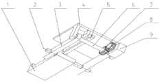
图1是本发明一种具有如厕和洗澡功能的康复护理床整体装配图;Fig. 1 is the overall assembly diagram of a kind of rehabilitation nursing bed with toilet and bathing functions of the present invention;
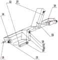
图2是本发明一种具有如厕和洗澡功能的康复护理床中腿部连杆示意图;2 is a schematic diagram of a leg link in a rehabilitation nursing bed with toilet and bathing functions of the present invention;
图3是本发明一种具有如厕和洗澡功能的康复护理床中第一床板和第二床板结构示意图;3 is a schematic structural diagram of a first bed board and a second bed board in a rehabilitation nursing bed with toilet and bath functions according to the present invention;
图4是本发明一种具有如厕和洗澡功能的康复护理床中腿部连杆示意辅图;4 is a schematic auxiliary diagram of a leg link in a rehabilitation nursing bed with toileting and bathing functions of the present invention;
图5是本发明一种具有如厕和洗澡功能的康复护理床整体装配辅图;Fig. 5 is an overall assembly diagram of a rehabilitation nursing bed with toileting and bathing functions according to the present invention;
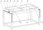
图6是本发明一种具有如厕和洗澡功能的康复护理床中洗澡功能示意图;6 is a schematic diagram of the bathing function in a rehabilitation nursing bed with toileting and bathing functions according to the present invention;
图7是本发明一种具有如厕和洗澡功能的康复护理床中洗澡功能结构示意辅图;FIG. 7 is a schematic diagram of the bathing function in a rehabilitation nursing bed with toilet and bathing functions according to the present invention;
图8是本发明一种具有如厕和洗澡功能的康复护理床中洗澡功能皮带示意辅图;Figure 8 is a schematic diagram of a belt with a bath function in a rehabilitation nursing bed with toilet and bath functions according to the present invention;
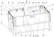
图9是本发明一种具有如厕和洗澡功能的康复护理床中臀部床面下侧机构装配图;9 is an assembly diagram of the lower side mechanism of the buttocks bed surface in a rehabilitation nursing bed with toileting and bathing functions according to the present invention;
图10是本发明一种具有如厕和洗澡功能的康复护理床中臀部床面下侧机构装配辅图;10 is an auxiliary assembly diagram of the lower side mechanism of the buttocks bed surface in a rehabilitation nursing bed with toileting and bathing functions according to the present invention;
图11是本发明一种具有如厕和洗澡功能的康复护理床中臀部床面示意图。Figure 11 is a schematic diagram of the buttocks bed surface of a rehabilitation nursing bed with toilet and bath functions according to the present invention.
图中,1.小腿床面连接连杆,2.连接轴A,3.大腿床面连接连杆,4.臀部床面,5.小腿床面导向连杆,6.连接轴B,7.啮合直齿轮A,8.啮合直齿轮B,9.电机A,10.电动推杆,11.床体前后支架,12.定位齿条,13.齿条啮合齿轮,14.电机B,15.床体支架导向轮,16.床体支架导轨槽,17.活动床板,18.整体两侧结构支架,19.小腿皮带卷轴,20.小腿啮合锥齿轮A,21.小腿啮合锥齿轮B,22.电机C,23.大腿啮合锥齿轮A,24.电机D,25.护垫更换机构,26.水洗式马桶机构,27.背部皮带卷轴,28.电机E,29.背部啮合锥齿轮A,30.背部啮合锥齿轮B,31.充气式浴缸,32.小腿皮带,33.大腿皮带,34.背部皮带,35.护垫转位啮合锥齿轮A,36.护垫转位啮合锥齿轮B,37.护垫装置转位转轴,38.电机F,39.电机G,40.护垫更换啮合锥齿轮A,41.护垫更换啮合锥齿轮B,42.马桶转位啮合锥齿轮A,43.马桶转位啮合锥齿轮B,44.电机H,45.护垫自收紧卷轴,46.电机驱动护垫收紧卷轴,47.水洗式马桶,48.马桶转位转轴,49.第二臀部床面,50.第一臀部床面,51.小腿床面,52.大腿床面,53.背部床面,54.支座A,55.支座B,56转轴,57.大腿皮带卷轴,58.大腿啮合锥齿轮B。In the figure, 1. calf bed surface connecting link, 2. connecting axis A, 3. thigh bed surface connecting link, 4. hip bed surface, 5. calf bed surface guiding link, 6. connecting axis B, 7. Meshing spur gear A, 8. Meshing spur gear B, 9. Motor A, 10. Electric push rod, 11. Front and rear brackets of bed body, 12. Positioning rack, 13. Rack meshing gear, 14. Motor B, 15. Guide wheel for bed support, 16. Guide rail groove for bed support, 17. Movable bed board, 18. Overall structure support on both sides, 19. Calf belt reel, 20. Calf meshing bevel gear A, 21. Calf meshing bevel gear B, 22 . Motor C, 23. Thigh meshing bevel gear A, 24. Motor D, 25. Pad replacement mechanism, 26. Flush toilet mechanism, 27. Back belt reel, 28. Motor E, 29. Back meshing bevel gear A, 30. Back meshing bevel gear B, 31. Inflatable bathtub, 32. Calf belt, 33. Thigh belt, 34. Back belt, 35. Pad indexing meshing bevel gear A, 36. Pad indexing meshing bevel gear B , 37. Pad device indexing shaft, 38. Motor F, 39. Motor G, 40. Pad replacement meshing bevel gear A, 41. Pad replacement meshing bevel gear B, 42. Toilet indexing meshing bevel gear A, 43. Toilet indexing meshing bevel gear B, 44. Motor H, 45. Pad self-tightening reel, 46. Motor-driven pad tightening reel, 47. Washable toilet, 48. Toilet indexing shaft, 49. Section Two buttocks bed surface, 50. First buttocks bed surface, 51. Calf bed surface, 52. Thigh bed surface, 53. Back bed surface, 54. Support A, 55. Support B, 56. Rotating shaft, 57. Thigh belt Reel, 58. Thigh meshing bevel gear B.
具体实施方式Detailed ways
下面结合附图和具体实施方式对本发明进行详细说明。The present invention will be described in detail below with reference to the accompanying drawings and specific embodiments.
本发明一种具有如厕和洗澡功能的康复护理床,结构如图1~图4所示,包括床体支架,床体支架11的上面设置有整体两侧结构支架18,整体两侧结构支架18沿长方向轴对称分为两半,整体两侧结构支架18上面设置有活动床板17,活动床板17沿长方向轴对称分为第一床板和第二床板,整体两侧结构支架18两半与第一床板和第二床板一一对应,第一床板和第二床板均由背部床面、臀部床面4、大腿床面52、小腿床面51依次通过转轴活动连接构成,位于所述第一床板上的所述臀部床面4为第一臀部床面50,位于第二床板的臀部床面4为第二臀部床面49,第一床板和第二床板均能沿床体支架11横向方向向外滑动翻折,臀部床面4中间位置处留有空位,活动床板17下面的床体支架11空间内还设置有浴缸机构,第一床板对应通孔位置处活动设置有护垫更换机构25,第二床板对应通孔位置处活动设置有水洗式马桶机构26。The present invention is a rehabilitation nursing bed with functions of toileting and bathing. The structure is shown in Figures 1 to 4, and includes a bed body support. The upper side of the
第一床板和第二床板的短边端部均通过电机安装板设置有电机B14,电机B14轴端分别用键和顶丝配合固定安装有齿条啮合齿轮13,与床板的短边对应位置的所述床体支架11上还设置有定位齿条12,齿条啮合齿轮13能够沿定位齿条12滑动,定位齿条12的两端处的床体支架11拐角处还设置有床体支架导轨槽16,与床体支架11拐角处对应位置的床板短边端部还设置有床体支架导向轮15,床体支架导轨槽16一直延伸至床体支架11竖直位置一段距离,四个床体支架导向轮15能够沿各自对应的床体支架导轨槽16向下滑动,通过四个电机的运动带动四个直齿轮旋转,使整体两侧结构支架18和对应的整体两侧床面17左右分离,又由于导向轮在导轨槽中定向运动,直至外翻后第一床板和第二床板的下沿到达床体支架导轨槽16末端,整体两侧结构支架18向床体两侧翻折。The short side ends of the first bed plate and the second bed plate are provided with a motor B14 through the motor mounting plate, and the shaft end of the motor B14 is fixedly installed with a
如图5所示,第一床板与第二床板结构相同,具体结构如下:背部床面53底部通过电动推杆10与活动床板17连接,电动推杆10一端固定于活动床板17上,电动推杆10另一端连接至背部床面53靠近臀部床面4的一端底部,在电动推杆10首尾端都有可供旋转的支座B55,且在背部床面53与活动床板17上都有与之对应的支座54,支座通过轴传入连接,支座B55和支座A54呈反向旋转关系,在电动推杆10伸长时,会有相对运动使得床面向上翻折一定角度;As shown in FIG. 5 , the structure of the first bed board is the same as that of the second bed board, and the specific structure is as follows: the bottom of the
如图4所示,臀部床面4与背部床面53之间通过转轴56连接,臀部床面4底部还通过电机支座安装有电机A9,电机A9的轴端通过键和顶丝固定位置的啮合直齿轮B8,大腿床面52下侧与两根大腿床面连接杆3用螺钉连接,大腿床面连接杆3的一端圆柱与在臀部床面4下侧的旋转支座上的连接轴6连接,在臀部床面4下侧的另一个旋转支座通过旋转轴与小腿床面导向连杆5的一段连接,小腿床面导向连接杆5的另一端与小腿床面连接杆1上的旋转支座通过转轴连接,小腿床面连接杆1上侧面有圆形通孔,用连接轴A2将其与两根大腿床面连接杆3的另一端圆孔相连,在连接轴B6上有通过键槽和顶丝固定位置的啮合直齿轮A7,啮合直齿轮A7和啮合直齿轮B8构成啮合关系,电机A9转动时可以带动大腿和小腿床面,使得小腿床面始终保持水平,大腿床面通过转轴向下翻折。As shown in FIG. 4 , the
转轴的两端与旋转支座之间均通过卡簧固定位置。Both ends of the rotating shaft and the rotating support are fixed in position by a circlip.
如图6、图7、图8所示,浴缸机构具体结构为:包括设置在所述背部床面53底面上的背部皮带卷轴27,一对背部皮带卷轴27均沿床体竖直方向设置且相互平行,背部皮带卷轴27的两端嵌进背部床面53底面两端部的支撑座内,第一床板与第二床板上对称设置的两个背部皮带卷轴27之间通过背部皮带34构成垂度可调的皮带承重面,用于支撑人体洗浴时的背部,背部皮带卷轴27其中一端还与背部啮合锥齿轮B30连接,背部啮合锥齿轮B30又与背部啮合锥齿轮A29啮合连接,背部啮合锥齿轮A29又与电机E28的输出轴连接,电机E28通过电机支架与背部床面53相连,在大腿床面52下侧的大腿皮带卷轴57两端以同样的方式固定在大腿床面下侧两端部的旋转支座内部,通过卡簧固定位置,大腿床面52还通过电机支座固定安装有电机D24,电机D24通过顶丝固定的大腿啮合锥齿轮B58与大腿皮带卷轴57上的大腿啮合锥齿轮A23构成啮合关系,一对大腿皮带卷轴57之间通过大腿皮带33连接构成垂度可调的皮带承重面,用于支撑人体洗浴时的大腿部;As shown in FIGS. 6 , 7 and 8 , the specific structure of the bathtub mechanism is as follows: it includes a
在所述小腿床面51下侧的小腿皮带卷轴19两端以同样的方式固定在小腿床面下侧两端部的旋转支座内部,通过卡簧固定位置,小腿床面51还通过电机支座固定安装有电机C22,电机C22通过顶丝固定的小腿啮合锥齿轮B21与小腿皮带卷轴19上的小腿啮合锥齿轮A20构成啮合关系,一对小腿皮带卷轴19之间通过小腿皮带32连接构成垂度可调的皮带承重面,用于支撑人体洗浴时的小腿部;The two ends of the
在两侧床面翻折到两侧的同时,背部皮带34、大腿皮带33、小腿皮带32能够同时通过各自连接的卷轴释放皮带充当床面,此时在床体底部的充气式浴缸31进行充气形成简易浴缸,继续放松皮带可以使皮带中部接触到浴缸底部。When the bed surfaces on both sides are folded to both sides, the
如图9、图10、图11所示,护垫更换机构25具体结构为:包括设置在第一臀部床面50底部的方形支架,方形支架底部设置有护垫装置转位轴37,护垫装置转位轴37与水洗式马桶机构26的转轴平行设置,即当护垫更换机构25位于臀部床面4中间位置的空位时,水洗式马桶机构26则旋转至第二臀部床面49底部,当水洗式马桶机构26位于所述臀部床面4中间位置的空位时,护垫更换机构25则旋转至第一臀部床面50底部,两者实现自由选择转换,护垫装置转位轴37的两端固定在方形支架底部对应位置处的旋转支座内,护垫装置转位轴37无齿轮的一端通过卡簧定位,护垫装置转位轴37另一端通过键和顶丝配合定位安装有护垫转位啮合锥齿轮A35,护垫转位啮合锥齿轮A35与护垫转位啮合锥齿轮B36构成啮合关系,护垫转位啮合锥齿轮B36安装于电机F38的输出轴端,电机F38通过电机支座安装在侧臀部床面50下侧,电机F38能够带动方形支架整体转动翻折,靠近护垫装置转位轴38的方形支架一侧还设置有护垫自收紧卷轴45,护垫自收紧卷轴45两端安装于方形支架的开孔内部并通过螺母定位固定,方形支架另一侧设置有电机驱动护垫收紧卷轴46,电机驱动护垫收紧卷轴46的伸出轴端通过键和顶丝配合定位安装有护垫更换啮合锥齿轮B41,护垫更换啮合锥齿轮B41与护垫更换啮合锥齿轮A40构成啮合关系,护垫更换啮合锥齿轮A40通过顶丝和键配合定位安装在电机G39的轴端,电机G39通过电机安装支座安装在方形支架上,通过电机G39转动带动电机驱动护垫收紧卷轴46转动。As shown in Fig. 9, Fig. 10, Fig. 11, the specific structure of the
水洗式马桶机构26具体结构为:包括设置在所述第二臀部床面49底部的马桶转位转轴48,马桶转位转轴48两端通过旋转支座A与第二臀部床面49底部固定,第二臀部床面49底部还设置有水洗式马桶47,水洗式马桶47上与第二臀部床面49底部的旋转支座A对应位置处也设置有两个旋转支座B,马桶转位转轴48同时也与旋转支座B连接,通过马桶转位转轴48将水洗式马桶47与第二臀部床面49实现关联,马桶转位转轴48无齿轮的一端用卡簧定位,马桶转位转轴48另一伸出端使用键和顶丝配合定位安装有马桶转位啮合锥齿轮B43,马桶转位啮合锥齿轮B43和马桶转位啮合锥齿轮A42构成啮合关系,马桶转位啮合锥齿轮A42通过键和顶丝定位安装于电机H44的轴端,电机H44过电机支座安装在第二臀部床面49下侧,通过电机H44的运动带动整体水洗式马桶47转动翻折,在水洗式马桶47马桶口下侧有收集污物的管道通向床侧的污物收集桶中,在排泄完成后第一时间将污物收集排出。The specific structure of the water-
本发明一种具有如厕和洗澡功能的康复护理床,在实际应用中,所有的电机都会与电源接通供电,具有如厕和洗澡功能的康复护理床工作原理如下:坐立功能原理:背部床面53、大腿床面52和小腿床面51初始为水平状态,在患者需要坐立时电动推杆10会由电控制伸长,电动推杆10首尾端都有可供旋转的支座B55,在背部床面53与活动床板17上都有与之对应的支座54,支座通过轴传入连接,支座B55和支座A54呈反向旋转关系,会有相对运动使得床面向上翻折一定角度,使患者上半身随之抬起。同时大腿床面52和小腿床面51由电机A9作为驱动,带动由各个连杆不见组成如图2的连杆机构,最终可以带动大腿和小腿床面,使得小腿床面始终保持水平,大腿床面通过转轴向下翻折,与背部床面53的动作结合可以使患者在床上形成坐立姿态,反向执行可以使之恢复到躺卧姿态。The present invention is a rehabilitation nursing bed with toileting and bathing functions. In practical application, all motors will be connected to the power supply for power supply. The working principle of the rehabilitation nursing bed with toileting and bathing functions is as follows: Sitting and standing function principle: back The
洗澡功能原理:在初始状态下整体两侧结构支架18中间相接触形成床面,在需要执行洗澡功能时,第一床板和第二床板的短边端部均有电机B14,电机B14,电机进行运动带动电机上的齿条啮合齿轮13在定位齿条12上分别向床体两侧运动,同时在小腿床面51下侧的小腿皮带卷轴19、大腿床面52下侧的大腿皮带卷轴57、背部床面53底面上的背部皮带卷轴27分别由电机C22、电机D24和电机E28驱动,带动对应的锥齿轮使得背部皮带34、大腿皮带33、小腿皮带32展开将患者托在皮带上。持续运行,由于床体支架导向轮15和床体支架导轨槽16的导向作用使得整体两侧结构支架18如图6向两侧翻折,翻折到位电机B14停止运行。电机C22、电机D24和电机E28继续动作使得背部皮带34、大腿皮带33、小腿皮带32能够同时通过各自连接的卷轴释放皮带充当床面,此时在床体底部的充气式浴缸31进行充气形成简易浴缸,继续放松皮带可以使皮带中部接触到浴缸底部如图8,在洗澡结束后,所有机构反向执行可以使得患者重新回到床面上。The principle of bathing function: in the initial state, the
排便和护垫更换功能原理:在所有机构的初始状态护垫更换机构25在床面的上侧如图11,而整体水洗式马桶47在另一侧床面的下侧如图9。在患者大小便失禁后,护垫更换机构25会由电机F38带动护垫装置转位轴37转动,使得护垫更换机构25翻折到床面下侧。此时通过电机G39转动带动电机驱动护垫收紧卷轴46转动,使得脏的护垫被收卷起来,同时护垫自收紧卷轴45会放出新的护垫,随后电机F38带动护垫装置转位轴37反向转动,使得机构恢复初始状态。在患者有意识需要进行排泄时,护垫更换机构25会由电机F38带动护垫装置转位轴37转动,使得护垫更换机构25翻折到床面下侧。随后电机H44的运动带动马桶转位转轴48转动使得整体水洗式马桶47转动翻折,转动到初始时护垫更换机构25所在的位置进行污物收集和转移。在操作结束后电机H44的运动带动马桶转位转轴48反向转动使得整体水洗式马桶47转动翻折回到初始位置,随后电机F38带动护垫装置转位轴37反向转动,使得护垫更换机构25恢复到初始位置。Defecation and pad replacement function principle: in the initial state of all mechanisms, the
Claims (7)
Translated fromChinesePriority Applications (1)
| Application Number | Priority Date | Filing Date | Title |
|---|---|---|---|
| CN202010229233.4ACN111407554B (en) | 2020-03-27 | 2020-03-27 | Rehabilitation nursing bed with toilet and bath functions |
Applications Claiming Priority (1)
| Application Number | Priority Date | Filing Date | Title |
|---|---|---|---|
| CN202010229233.4ACN111407554B (en) | 2020-03-27 | 2020-03-27 | Rehabilitation nursing bed with toilet and bath functions |
Publications (2)
| Publication Number | Publication Date |
|---|---|
| CN111407554Atrue CN111407554A (en) | 2020-07-14 |
| CN111407554B CN111407554B (en) | 2024-03-29 |
Family
ID=71485310
Family Applications (1)
| Application Number | Title | Priority Date | Filing Date |
|---|---|---|---|
| CN202010229233.4AActiveCN111407554B (en) | 2020-03-27 | 2020-03-27 | Rehabilitation nursing bed with toilet and bath functions |
Country Status (1)
| Country | Link |
|---|---|
| CN (1) | CN111407554B (en) |
Cited By (2)
| Publication number | Priority date | Publication date | Assignee | Title |
|---|---|---|---|---|
| CN112190418A (en)* | 2020-09-16 | 2021-01-08 | 谢碧清 | Nursing bed |
| CN112451258A (en)* | 2020-12-14 | 2021-03-09 | 湖南工程学院 | Multifunctional self-help old-person bed |
Citations (8)
| Publication number | Priority date | Publication date | Assignee | Title |
|---|---|---|---|---|
| US5737786A (en)* | 1996-03-01 | 1998-04-14 | Yamamoto; Tsuneo | Collapsible bed structure for bed-ridden invalids |
| JP2011161197A (en)* | 2010-02-15 | 2011-08-25 | Nobuhiro Aoki | Medical care equipment permitting nursing care simultaneously with bathing without transferring patient's body |
| CN103417344A (en)* | 2012-05-22 | 2013-12-04 | 李婧 | Box-type combined intelligentized multifunctional special-nursing hospital bed |
| US20140310875A1 (en)* | 2011-12-24 | 2014-10-23 | Kazuyoshi Iida | Caregiving bed |
| CN106344307A (en)* | 2016-10-11 | 2017-01-25 | 丁春玲 | Nursing bath bed |
| CN209172750U (en)* | 2018-05-07 | 2019-07-30 | 威海威高齐全医疗设备有限公司 | A kind of nursing bed |
| CN110652405A (en)* | 2019-10-28 | 2020-01-07 | 河南孝道科技有限公司 | A fully automatic medical nursing bed for the elderly or critically ill patients |
| CN213098909U (en)* | 2020-03-27 | 2021-05-04 | 西安理工大学 | Multifunctional rehabilitation nursing bed |
- 2020
- 2020-03-27CNCN202010229233.4Apatent/CN111407554B/enactiveActive
Patent Citations (8)
| Publication number | Priority date | Publication date | Assignee | Title |
|---|---|---|---|---|
| US5737786A (en)* | 1996-03-01 | 1998-04-14 | Yamamoto; Tsuneo | Collapsible bed structure for bed-ridden invalids |
| JP2011161197A (en)* | 2010-02-15 | 2011-08-25 | Nobuhiro Aoki | Medical care equipment permitting nursing care simultaneously with bathing without transferring patient's body |
| US20140310875A1 (en)* | 2011-12-24 | 2014-10-23 | Kazuyoshi Iida | Caregiving bed |
| CN103417344A (en)* | 2012-05-22 | 2013-12-04 | 李婧 | Box-type combined intelligentized multifunctional special-nursing hospital bed |
| CN106344307A (en)* | 2016-10-11 | 2017-01-25 | 丁春玲 | Nursing bath bed |
| CN209172750U (en)* | 2018-05-07 | 2019-07-30 | 威海威高齐全医疗设备有限公司 | A kind of nursing bed |
| CN110652405A (en)* | 2019-10-28 | 2020-01-07 | 河南孝道科技有限公司 | A fully automatic medical nursing bed for the elderly or critically ill patients |
| CN213098909U (en)* | 2020-03-27 | 2021-05-04 | 西安理工大学 | Multifunctional rehabilitation nursing bed |
Cited By (2)
| Publication number | Priority date | Publication date | Assignee | Title |
|---|---|---|---|---|
| CN112190418A (en)* | 2020-09-16 | 2021-01-08 | 谢碧清 | Nursing bed |
| CN112451258A (en)* | 2020-12-14 | 2021-03-09 | 湖南工程学院 | Multifunctional self-help old-person bed |
Also Published As
| Publication number | Publication date |
|---|---|
| CN111407554B (en) | 2024-03-29 |
Similar Documents
| Publication | Publication Date | Title |
|---|---|---|
| CN104127289B (en) | Split type robot nursing bed having rehabilitation training function | |
| CN102824254B (en) | Auxiliary nursing moving and taking device | |
| CN202802005U (en) | Auxiliary nursing transfer device | |
| CN202409329U (en) | Care bed special for paralytic patient | |
| CN205163467U (en) | Novel multifunctional nursing bed | |
| CN111053661A (en) | A detachable multifunctional electric wheelchair bed | |
| CN112294570B (en) | Intelligent nursing bed with integrated control of bed plate opening and closing and closestool lifting | |
| CN108888429A (en) | It is a kind of with turn over and convenient for excretory function Multi-functional wheel chair bed | |
| CN111407554A (en) | A rehabilitation nursing bed with toilet and bath functions | |
| CN211535270U (en) | Detachable multifunctional electric wheelchair bed | |
| CN112022557B (en) | A multifunctional rehabilitation nursing bed | |
| CN105250092A (en) | New type multifunctional nursing bed | |
| CN209187292U (en) | Turning over and lifting back mechanism of wheelchair combination nursing bed | |
| CN209203816U (en) | It is a kind of with turn over and convenient for excretory function Multi-functional wheel chair bed | |
| CN212730219U (en) | Wheelchair bed capable of realizing trousers wearing and taking off function | |
| CN107693251A (en) | A kind of mattress rolling formula is intellectual nursing bed | |
| CN112957200B (en) | A foldable and widened bed suitable for bedridden people | |
| CN110897802A (en) | Multifunctional combined wheelchair bed nursing system | |
| CN213098909U (en) | Multifunctional rehabilitation nursing bed | |
| CN112089553A (en) | Wheelchair bed capable of realizing trousers wearing and taking off function | |
| CN116370219B (en) | Multifunctional intelligent nursing bed | |
| WO2013185260A1 (en) | Multifunctional full-automation care bed | |
| CN216148408U (en) | A wheelchair combination bed with toilet | |
| CN215385340U (en) | Multifunctional nursing bed | |
| CN110916941B (en) | A transfer nursing robot with a fixed sitting posture |
Legal Events
| Date | Code | Title | Description |
|---|---|---|---|
| PB01 | Publication | ||
| PB01 | Publication | ||
| SE01 | Entry into force of request for substantive examination | ||
| SE01 | Entry into force of request for substantive examination | ||
| GR01 | Patent grant | ||
| GR01 | Patent grant |