CN111407464A - Accommodating intraocular lens and method of manufacture - Google Patents
Accommodating intraocular lens and method of manufactureDownload PDFInfo
- Publication number
- CN111407464A CN111407464ACN202010011878.0ACN202010011878ACN111407464ACN 111407464 ACN111407464 ACN 111407464ACN 202010011878 ACN202010011878 ACN 202010011878ACN 111407464 ACN111407464 ACN 111407464A
- Authority
- CN
- China
- Prior art keywords
- optic
- intraocular lens
- peripheral
- haptics
- optical
- Prior art date
- Legal status (The legal status is an assumption and is not a legal conclusion. Google has not performed a legal analysis and makes no representation as to the accuracy of the status listed.)
- Granted
Links
Images


Classifications
- A—HUMAN NECESSITIES
- A61—MEDICAL OR VETERINARY SCIENCE; HYGIENE
- A61F—FILTERS IMPLANTABLE INTO BLOOD VESSELS; PROSTHESES; DEVICES PROVIDING PATENCY TO, OR PREVENTING COLLAPSING OF, TUBULAR STRUCTURES OF THE BODY, e.g. STENTS; ORTHOPAEDIC, NURSING OR CONTRACEPTIVE DEVICES; FOMENTATION; TREATMENT OR PROTECTION OF EYES OR EARS; BANDAGES, DRESSINGS OR ABSORBENT PADS; FIRST-AID KITS
- A61F2/00—Filters implantable into blood vessels; Prostheses, i.e. artificial substitutes or replacements for parts of the body; Appliances for connecting them with the body; Devices providing patency to, or preventing collapsing of, tubular structures of the body, e.g. stents
- A61F2/02—Prostheses implantable into the body
- A61F2/14—Eye parts, e.g. lenses or corneal implants; Artificial eyes
- A61F2/16—Intraocular lenses
- A61F2/1601—Lens body having features to facilitate aqueous fluid flow across the intraocular lens, e.g. for pressure equalization or nutrient delivery
- A—HUMAN NECESSITIES
- A61—MEDICAL OR VETERINARY SCIENCE; HYGIENE
- A61F—FILTERS IMPLANTABLE INTO BLOOD VESSELS; PROSTHESES; DEVICES PROVIDING PATENCY TO, OR PREVENTING COLLAPSING OF, TUBULAR STRUCTURES OF THE BODY, e.g. STENTS; ORTHOPAEDIC, NURSING OR CONTRACEPTIVE DEVICES; FOMENTATION; TREATMENT OR PROTECTION OF EYES OR EARS; BANDAGES, DRESSINGS OR ABSORBENT PADS; FIRST-AID KITS
- A61F2/00—Filters implantable into blood vessels; Prostheses, i.e. artificial substitutes or replacements for parts of the body; Appliances for connecting them with the body; Devices providing patency to, or preventing collapsing of, tubular structures of the body, e.g. stents
- A61F2/02—Prostheses implantable into the body
- A61F2/14—Eye parts, e.g. lenses or corneal implants; Artificial eyes
- A61F2/16—Intraocular lenses
- A61F2/1613—Intraocular lenses having special lens configurations, e.g. multipart lenses; having particular optical properties, e.g. pseudo-accommodative lenses, lenses having aberration corrections, diffractive lenses, lenses for variably absorbing electromagnetic radiation, lenses having variable focus
- A61F2/1624—Intraocular lenses having special lens configurations, e.g. multipart lenses; having particular optical properties, e.g. pseudo-accommodative lenses, lenses having aberration corrections, diffractive lenses, lenses for variably absorbing electromagnetic radiation, lenses having variable focus having adjustable focus; power activated variable focus means, e.g. mechanically or electrically by the ciliary muscle or from the outside
- A61F2/1635—Intraocular lenses having special lens configurations, e.g. multipart lenses; having particular optical properties, e.g. pseudo-accommodative lenses, lenses having aberration corrections, diffractive lenses, lenses for variably absorbing electromagnetic radiation, lenses having variable focus having adjustable focus; power activated variable focus means, e.g. mechanically or electrically by the ciliary muscle or from the outside for changing shape
- A—HUMAN NECESSITIES
- A61—MEDICAL OR VETERINARY SCIENCE; HYGIENE
- A61F—FILTERS IMPLANTABLE INTO BLOOD VESSELS; PROSTHESES; DEVICES PROVIDING PATENCY TO, OR PREVENTING COLLAPSING OF, TUBULAR STRUCTURES OF THE BODY, e.g. STENTS; ORTHOPAEDIC, NURSING OR CONTRACEPTIVE DEVICES; FOMENTATION; TREATMENT OR PROTECTION OF EYES OR EARS; BANDAGES, DRESSINGS OR ABSORBENT PADS; FIRST-AID KITS
- A61F2/00—Filters implantable into blood vessels; Prostheses, i.e. artificial substitutes or replacements for parts of the body; Appliances for connecting them with the body; Devices providing patency to, or preventing collapsing of, tubular structures of the body, e.g. stents
- A61F2/02—Prostheses implantable into the body
- A61F2/14—Eye parts, e.g. lenses or corneal implants; Artificial eyes
- A61F2/16—Intraocular lenses
- A61F2/1613—Intraocular lenses having special lens configurations, e.g. multipart lenses; having particular optical properties, e.g. pseudo-accommodative lenses, lenses having aberration corrections, diffractive lenses, lenses for variably absorbing electromagnetic radiation, lenses having variable focus
- A61F2/1637—Correcting aberrations caused by inhomogeneities; correcting intrinsic aberrations, e.g. of the cornea, of the surface of the natural lens, aspheric, cylindrical, toric lenses
- A61F2/164—Aspheric lenses
- G—PHYSICS
- G02—OPTICS
- G02B—OPTICAL ELEMENTS, SYSTEMS OR APPARATUS
- G02B3/00—Simple or compound lenses
- G02B3/12—Fluid-filled or evacuated lenses
- A—HUMAN NECESSITIES
- A61—MEDICAL OR VETERINARY SCIENCE; HYGIENE
- A61F—FILTERS IMPLANTABLE INTO BLOOD VESSELS; PROSTHESES; DEVICES PROVIDING PATENCY TO, OR PREVENTING COLLAPSING OF, TUBULAR STRUCTURES OF THE BODY, e.g. STENTS; ORTHOPAEDIC, NURSING OR CONTRACEPTIVE DEVICES; FOMENTATION; TREATMENT OR PROTECTION OF EYES OR EARS; BANDAGES, DRESSINGS OR ABSORBENT PADS; FIRST-AID KITS
- A61F2/00—Filters implantable into blood vessels; Prostheses, i.e. artificial substitutes or replacements for parts of the body; Appliances for connecting them with the body; Devices providing patency to, or preventing collapsing of, tubular structures of the body, e.g. stents
- A61F2/02—Prostheses implantable into the body
- A61F2/14—Eye parts, e.g. lenses or corneal implants; Artificial eyes
- A61F2/16—Intraocular lenses
- A61F2/1662—Instruments for inserting intraocular lenses into the eye
- A61F2/167—Instruments for inserting intraocular lenses into the eye with pushable plungers
- A—HUMAN NECESSITIES
- A61—MEDICAL OR VETERINARY SCIENCE; HYGIENE
- A61F—FILTERS IMPLANTABLE INTO BLOOD VESSELS; PROSTHESES; DEVICES PROVIDING PATENCY TO, OR PREVENTING COLLAPSING OF, TUBULAR STRUCTURES OF THE BODY, e.g. STENTS; ORTHOPAEDIC, NURSING OR CONTRACEPTIVE DEVICES; FOMENTATION; TREATMENT OR PROTECTION OF EYES OR EARS; BANDAGES, DRESSINGS OR ABSORBENT PADS; FIRST-AID KITS
- A61F2/00—Filters implantable into blood vessels; Prostheses, i.e. artificial substitutes or replacements for parts of the body; Appliances for connecting them with the body; Devices providing patency to, or preventing collapsing of, tubular structures of the body, e.g. stents
- A61F2/02—Prostheses implantable into the body
- A61F2/14—Eye parts, e.g. lenses or corneal implants; Artificial eyes
- A61F2/16—Intraocular lenses
- A61F2002/1681—Intraocular lenses having supporting structure for lens, e.g. haptics
- A61F2002/1682—Intraocular lenses having supporting structure for lens, e.g. haptics having mechanical force transfer mechanism to the lens, e.g. for accommodating lenses
- A—HUMAN NECESSITIES
- A61—MEDICAL OR VETERINARY SCIENCE; HYGIENE
- A61F—FILTERS IMPLANTABLE INTO BLOOD VESSELS; PROSTHESES; DEVICES PROVIDING PATENCY TO, OR PREVENTING COLLAPSING OF, TUBULAR STRUCTURES OF THE BODY, e.g. STENTS; ORTHOPAEDIC, NURSING OR CONTRACEPTIVE DEVICES; FOMENTATION; TREATMENT OR PROTECTION OF EYES OR EARS; BANDAGES, DRESSINGS OR ABSORBENT PADS; FIRST-AID KITS
- A61F2/00—Filters implantable into blood vessels; Prostheses, i.e. artificial substitutes or replacements for parts of the body; Appliances for connecting them with the body; Devices providing patency to, or preventing collapsing of, tubular structures of the body, e.g. stents
- A61F2/02—Prostheses implantable into the body
- A61F2/14—Eye parts, e.g. lenses or corneal implants; Artificial eyes
- A61F2/16—Intraocular lenses
- A61F2002/1681—Intraocular lenses having supporting structure for lens, e.g. haptics
- A61F2002/16901—Supporting structure conforms to shape of capsular bag
- A—HUMAN NECESSITIES
- A61—MEDICAL OR VETERINARY SCIENCE; HYGIENE
- A61F—FILTERS IMPLANTABLE INTO BLOOD VESSELS; PROSTHESES; DEVICES PROVIDING PATENCY TO, OR PREVENTING COLLAPSING OF, TUBULAR STRUCTURES OF THE BODY, e.g. STENTS; ORTHOPAEDIC, NURSING OR CONTRACEPTIVE DEVICES; FOMENTATION; TREATMENT OR PROTECTION OF EYES OR EARS; BANDAGES, DRESSINGS OR ABSORBENT PADS; FIRST-AID KITS
- A61F2240/00—Manufacturing or designing of prostheses classified in groups A61F2/00 - A61F2/26 or A61F2/82 or A61F9/00 or A61F11/00 or subgroups thereof
- A61F2240/001—Designing or manufacturing processes
- G—PHYSICS
- G02—OPTICS
- G02B—OPTICAL ELEMENTS, SYSTEMS OR APPARATUS
- G02B3/00—Simple or compound lenses
- G02B3/02—Simple or compound lenses with non-spherical faces
- G02B3/04—Simple or compound lenses with non-spherical faces with continuous faces that are rotationally symmetrical but deviate from a true sphere, e.g. so called "aspheric" lenses
Landscapes
- Health & Medical Sciences (AREA)
- Ophthalmology & Optometry (AREA)
- Physics & Mathematics (AREA)
- Biomedical Technology (AREA)
- Vascular Medicine (AREA)
- Oral & Maxillofacial Surgery (AREA)
- Transplantation (AREA)
- Engineering & Computer Science (AREA)
- Veterinary Medicine (AREA)
- Heart & Thoracic Surgery (AREA)
- Cardiology (AREA)
- Life Sciences & Earth Sciences (AREA)
- Animal Behavior & Ethology (AREA)
- General Health & Medical Sciences (AREA)
- Public Health (AREA)
- General Physics & Mathematics (AREA)
- Optics & Photonics (AREA)
- Fluid Mechanics (AREA)
- Prostheses (AREA)
Abstract
Description
Translated fromChinese本分案申请是基于申请号为201680064380.2,申请日为2016年11月07日,发明名称为“可调节人工晶状体和制造方法”的中国专利申请的分案申请。该中国专利申请为国际申请号为PCT/US2016/060799的国际申请的中国国家阶段。This divisional application is based on the divisional application of the Chinese patent application with the application number of 201680064380.2 and the filing date of November 7, 2016, and the invention title is "Adjustable Intraocular Lens and Manufacturing Method". This Chinese patent application is the Chinese national phase of the international application with the international application number PCT/US2016/060799.
相关申请的交叉引用CROSS-REFERENCE TO RELATED APPLICATIONS
本申请要求以下美国临时专利申请的优先权:2015年11月6日提交的第62/252,260号;2016年4月12日提交的第62/321,678号;2016年7月1日提交的第62/357,785号;2016年4月12日提交的第62/321,704号;2016年4月12日提交的第62/321,666号;2016年4月12日提交的第62/321,665号;2016年4月12日提交的第62/321,705号;2016年4月12日提交的第62/321,684号;2016年4月12日提交的第62/321,670号和2016年8月19日提交的第62/377,402号;其公开内容全部通过引用并入本文。This application claims priority to the following US provisional patent applications: No. 62/252,260, filed Nov. 6, 2015; No. 62/321,678, filed April 12, 2016; /357,785; 62/321,704, filed April 12, 2016; 62/321,666, April 12, 2016; 62/321,665, April 12, 2016 62/321,705, filed 12; 62/321,684, April 12, 2016; 62/321,670, April 12, 2016; and 62/377,402, August 19, 2016 No.; its disclosure is incorporated herein by reference in its entirety.
参考引用reference
本说明书中提及的所有出版物和专利申请均通过引用并入本文,其程度如同每个单独的出版物或专利申请被具体和单独地指示为通过引用并入。All publications and patent applications mentioned in this specification are herein incorporated by reference to the same extent as if each individual publication or patent application was specifically and individually indicated to be incorporated by reference.
背景技术Background technique
已经描述了流体驱动的可调节人工晶状体。本公开描述可以为一些流体驱动的可调节人工晶状体提供益处的示例性人工晶状体的各个方面。例如,具有非球面形状的流体驱动人工晶状体在制造后可能是有益的。Fluid-actuated accommodating intraocular lenses have been described. The present disclosure describes various aspects of exemplary intraocular lenses that may provide benefits for some fluid-actuated accommodating intraocular lenses. For example, fluid-actuated intraocular lenses with aspherical shapes may be beneficial after manufacture.
发明内容SUMMARY OF THE INVENTION
本公开的一个方面是一种制造可调节人工晶状体的光学部以具有非球面晶状体表面的方法,包括:提供包括前部元件和后部元件的光学部,所述前部元件和后部元件至少部分地限定光学流体腔室,其中前部元件和后部元件中的至少一者具有球面的外表面;在将可调节人工晶状体插入到眼睛中之前,将前部元件和后部元件中的至少一者的形状从球面构型改变为非球面构型。One aspect of the present disclosure is a method of making an optic of an accommodating intraocular lens to have an aspheric lens surface, comprising: providing an optic including an anterior element and a posterior element, the anterior and posterior elements at least an optical fluid chamber is partially defined, wherein at least one of the anterior element and the posterior element has a spherical outer surface; prior to inserting the accommodating intraocular lens into the eye, at least one of the anterior element and the posterior element is The shape of one changes from a spherical configuration to an aspherical configuration.
在一些实施例中,将前部元件和后部元件中的至少一者的形状从球面构型改变成非球面构型包括向流体腔室添加流体,以增加光学腔室内的流体压力并且导致前部元件和后部元件中的至少一者从球面构型变形为非球面构型。在添加流体之前,该方法可以包括将至少一个襻(haptic)固定到光学部。In some embodiments, changing the shape of at least one of the anterior element and the posterior element from a spherical configuration to an aspherical configuration includes adding fluid to the fluid chamber to increase fluid pressure within the optical chamber and cause anterior At least one of the front element and the rear element is deformed from a spherical configuration to an aspherical configuration. Before adding the fluid, the method can include securing at least one haptic to the optic.
在一些实施例中,提供光学部包括将前部元件结合到后部元件。In some embodiments, providing the optics includes bonding the front element to the rear element.
在一些实施例中,该方法还包括加工前部元件和后部元件中的至少一者。In some embodiments, the method further includes machining at least one of the front element and the rear element.
在一些实施例中,在将前部元件和后部元件中的至少一者的形状从球面构型改变成非球面构型之前,该光学部具有10-15D基础状态。In some embodiments, the optic has a 10-15D base state prior to changing the shape of at least one of the front element and the rear element from a spherical configuration to an aspheric configuration.
本公开的一个方面是一种流体填充的人工晶状体,包括:光学部分,包括具有前部光学表面的前部元件和具有后部光学表面的后部元件,前部元件和后部元件限定光学流体腔室,其中在插入眼睛之前,前部光学表面和后部光学表面中的至少一者在制造状态下具有非球面构型。One aspect of the present disclosure is a fluid-filled intraocular lens comprising: an optic portion including an anterior element having an anterior optical surface and a posterior element having a posterior optical surface, the anterior element and the posterior element defining an optical fluid A chamber in which at least one of the anterior optical surface and the posterior optical surface has an aspheric configuration in the as-manufactured state prior to insertion into the eye.
本公开的一个方面是一种人工晶状体,包括:光学部分;以及包括周边流体腔室的周边部分,在经过光学部分的光轴的平面中,周边部分具有横截面,其中流体腔室设置在周边部分的径向外部中,并且其中周边腔室的径向内部是非流体的。One aspect of the present disclosure is an intraocular lens comprising: an optic portion; and a perimeter portion including a perimeter fluid chamber, the perimeter portion having a cross-section in a plane passing through an optical axis of the optic portion, wherein the fluid chamber is disposed at the perimeter in the radially outer portion of the portion, and in which the radially inner portion of the peripheral chamber is non-fluid.
本公开的一个方面是人工晶状体,包括:光学部分;以及包括周边流体腔室的周边部分,在经过光学部分的光轴的平面的横截面中,以及在与经过光学部分的中点的光学部分的光轴正交的方向上,周边部分具有的径向内部流体腔室壁厚为径向外部流体腔室壁厚的四到二十倍之间。One aspect of the present disclosure is an intraocular lens comprising: an optic portion; and a peripheral portion including a peripheral fluid chamber, in cross-section through a plane of an optical axis of the optic portion, and in the optic portion passing through a midpoint of the optic portion The peripheral portion has a radially inner fluid chamber wall thickness between four and twenty times the radially outer fluid chamber wall thickness in a direction orthogonal to the optical axis of .
本公开的一个方面是人工晶状体,包括:光学部分;以及包括周边流体腔室的周边部分,在经过光学部分的光轴的平面的横截面中,周边部分具有的外表面关于经过周边部分并且平行于光学部分的光轴的每个轴线不对称,并且其中在与经过周边部分的中点的光学部分的光轴正交的方向上,周边部分具有的径向内部流体腔室壁厚大于径向外部流体腔室壁厚。One aspect of the present disclosure is an intraocular lens comprising: an optic portion; and a perimeter portion including a perimeter fluid chamber, the perimeter portion having, in a cross-section through a plane of an optical axis of the optic portion, an outer surface that is parallel with respect to passing through the perimeter portion Asymmetric with respect to each axis of the optical axis of the optic portion, and wherein the perimeter portion has a radially inner fluid chamber wall thickness greater than the radial External fluid chamber wall thickness.
本公开的一个方面是一种人工晶状体,包括:光学部分;以及包括周边流体腔室的周边部分,在经过光学部分的光轴的平面的横截面中,周边部分具有沿前后方向测量的高度尺寸,其中在周边部分的径向外半部分中的周边部分的最大高度大于在周边部分的径向内半部分中的周边部分的最大高度。One aspect of the present disclosure is an intraocular lens comprising: an optical portion; and a peripheral portion including a peripheral fluid chamber, the peripheral portion having a height dimension measured in an anterior-posterior direction in a cross-section through a plane of an optical axis of the optical portion , wherein the maximum height of the peripheral portion in the radially outer half of the peripheral portion is greater than the maximum height of the peripheral portion in the radially inner half of the peripheral portion.
本公开的一个方面是一种人工晶状体,包括:光学部分,该光学部分在联接处联接到周边部分,该联接包括周边部分的径向内部表面,该内部表面与光学部分的径向外部周边边缘接口接合。One aspect of the present disclosure is an intraocular lens comprising: an optic portion coupled to a peripheral portion at a coupling, the coupling comprising a radially inner surface of the peripheral portion, the inner surface and a radially outer peripheral edge of the optic portion interface engagement.
在一些实施例中,周边部分的径向内部表面具有第一端部,所述第一端部具有与内部表面的第二端部不同的构造。周边部分可以包括具有联接端部和自由端部的襻,第一端部比联接端部更靠近襻自由端部。襻可以具有跟随光学部从襻联接端部到自由端部的径向外部周边曲率的构造。In some embodiments, the radially inner surface of the peripheral portion has a first end having a different configuration than the second end of the inner surface. The peripheral portion may include a haptic having a coupling end and a free end, the first end being closer to the free end of the haptic than the coupling end. The haptics may have a configuration that follows the radially outer peripheral curvature of the optic from the haptic coupling end to the free end.
在一些实施例中,第一端部具有比径向内部表面的第二端部大的表面积。第一端部可以具有锥形端部构型,其中锥形朝向周边部分的自由端部。In some embodiments, the first end has a larger surface area than the second end of the radially inner surface. The first end may have a tapered end configuration with the taper towards the free end of the peripheral portion.
在一些实施例中,周边部分的径向内部表面限定周边部分流体端口。In some embodiments, the radially inner surface of the peripheral portion defines peripheral portion fluid ports.
本公开的一个方面是一种人工晶状体,包括:光学体,从光学体的周边表面径向向外延伸的突起部以及具有固定到突起部的第一部分的周边非光学体。One aspect of the present disclosure is an intraocular lens comprising an optical body, a protrusion extending radially outward from a peripheral surface of the optical body, and a peripheral non-optical body having a first portion secured to the protrusion.
在一些实施例中,周边非光学体的第一部分的径向内部表面跟随突起部的径向周边表面。In some embodiments, the radially inner surface of the first portion of the peripheral non-optical body follows the radially peripheral surface of the protrusion.
在一些实施例中,突起部和第一部分通过可选的平坦或弯曲的相对表面可选的平坦或弯曲的相对表面在对接接合处接口接合。In some embodiments, the protrusion and the first portion are interfaced at the butt joint by an optional flat or curved opposing surface.
在一些实施例中,突起部的径向周边表面包括平坦表面,可选地完全平坦。周边非光学体的第一部分的径向内部表面可以包括平坦表面,可选地完全平坦。In some embodiments, the radially peripheral surface of the protrusion includes a flat surface, optionally completely flat. The radially inner surface of the first portion of the peripheral non-optical body may comprise a flat surface, optionally completely flat.
在一些实施例中,突起部的径向周边表面包括弯曲表面,可选地完全弯曲。周边非光学体的第一部分的径向内部表面可以包括弯曲表面,可选地全部弯曲。In some embodiments, the radially peripheral surface of the protrusion includes a curved surface, optionally fully curved. The radially inner surface of the first portion of the peripheral non-optical body may comprise a curved surface, optionally fully curved.
在一些实施例中,突起部的径向周边表面比光学体的周边表面距光学体的中心远10微米至1mm之间,可选地10微米至500微米之间。In some embodiments, the radial peripheral surface of the protrusion is between 10 micrometers and 1 mm, optionally between 10 micrometers and 500 micrometers further from the center of the optical body than the peripheral surface of the optical body.
在一些实施例中,突起部从光学体的周边表面延伸10微米至1mm之间,可选地10微米至500微米之间。In some embodiments, the protrusions extend between 10 and 1 mm, optionally between 10 and 500 microns, from the peripheral surface of the optical body.
在一些实施例中,光学体和突起部是单个整体。In some embodiments, the optical body and the protrusion are a single unitary body.
在一些实施例中,突起部附接到光学体。In some embodiments, the protrusion is attached to the optical body.
在一些实施例中,光学体包括后部元件和前部元件,可选地在两者之间限定流体腔室。后部元件可以包括突起部。前部元件可以包括突起部。In some embodiments, the optical body includes a rear element and a front element, optionally defining a fluid chamber therebetween. The rear element may include protrusions. The front element may include protrusions.
在一些实施例中,周边非光学体还包括远离第一部分设置的自由的第二部分。In some embodiments, the peripheral non-optical body further includes a free second portion disposed remote from the first portion.
在一些实施例中,周边非光学体包括周边流体腔室。In some embodiments, the peripheral non-optical body includes a peripheral fluid chamber.
在一些实施例中,突起部包括至少一个通道,并且可选地包括至少两个通道,所述通道与周边非光学体中的周边流体腔室流体连通。In some embodiments, the protrusion includes at least one channel, and optionally at least two channels, in fluid communication with a peripheral fluid chamber in the peripheral non-optical body.
在一些实施例中,周边非光学体具有联接到突起部的径向内部表面,所述径向内部表面可选地具有轻微弯曲,其中突起部设置在光学体的径向外部周边边缘上。In some embodiments, the peripheral non-optical body has a radially inner surface, optionally with a slight curvature, coupled to the protrusions, wherein the protrusions are disposed on the radially outer peripheral edge of the optical body.
在一些实施例中,周边非光学体适于响应于由于睫状肌运动引起的周边非光学体上的力而变形,从而在周边非光学体中的周边流体腔室与光学体中的光学流体腔室之间移动流体,以改变人工晶状体的光学参数。In some embodiments, the peripheral non-optical body is adapted to deform in response to forces on the peripheral non-optical body due to movement of the ciliary muscle such that the peripheral fluid chamber in the peripheral non-optical body and the optical fluid in the optical body Fluid is moved between the chambers to change the optical parameters of the intraocular lens.
在一些实施例中,周边非光学体包括被构造为与突起部接口接合的开口。In some embodiments, the peripheral non-optical body includes an opening configured to interface with the protrusion.
在一些实施例中,突起部的尺寸和构造被设计成设置在周边非光学体内的开口中并与其接口接合。In some embodiments, the protrusions are sized and configured to be disposed in and interfaced with openings in the peripheral non-optical body.
本公开的一个方面是一种人工晶状体,其包括光学体和周边非光学体,在俯视图中光学体具有至少一部分为弧的外部边缘,并且其中周边非光学体在相对于弧的曲线径向向外的位置处联接到光学体突起部。One aspect of the present disclosure is an intraocular lens comprising an optic body and a peripheral non-optical body, the optical body having an outer edge that is at least partially arcuate in plan view, and wherein the peripheral non-optical body is radially oriented relative to the curve of the arc is coupled to the optic body protrusion at an outer location.
本公开的一个方面是一种人工晶状体,其中第一和第二部件之间的粘合剂具有介于约0.4和1000MPa之间,例如介于约1MPa和600MPa之间的弹性模量。One aspect of the present disclosure is an intraocular lens wherein the adhesive between the first and second components has an elastic modulus between about 0.4 and 1000 MPa, eg, between about 1 MPa and 600 MPa.
本公开的一个方面是一种人工晶状体,其中粘合剂是人工晶状体的第一聚合物材料的可交联聚合物的50-85%。One aspect of the present disclosure is an intraocular lens, wherein the binder is 50-85% of the cross-linkable polymer of the first polymeric material of the intraocular lens.
本公开的一个方面是一种人工晶状体,其中粘合剂包含7.5%至30%的反应性丙烯酸类单体稀释剂。One aspect of the present disclosure is an intraocular lens, wherein the adhesive comprises 7.5% to 30% of a reactive acrylic monomer diluent.
本公开的一个方面是一种人工晶状体,其中粘合剂包含含量在2.5%和30%之间的甲基丙烯酸月桂酯或类似材料。One aspect of the present disclosure is an intraocular lens wherein the adhesive comprises lauryl methacrylate or similar material in an amount between 2.5% and 30%.
本公开的一个方面是一种人工晶状体,可选地是可调节的,包括:光学部分;周边部分;以及沿着周边部分的至少一部分长度延伸的至少一个脊。One aspect of the present disclosure is an intraocular lens, optionally adjustable, comprising: an optic portion; a peripheral portion; and at least one ridge extending along at least a portion of the length of the peripheral portion.
本公开的一个方面是一种人工晶状体,其中俯视图中的第一襻覆盖(可选地锥形)第二襻。One aspect of the present disclosure is an intraocular lens in which a first haptic in top view overlies (optionally tapered) a second haptic.
本公开的一个方面是一种人工晶状体,可选地是可调节的,包括:光学部分;以及联接到光学部分的周边部分,周边部分包括第一襻和第二襻,其中第一襻和第二襻被构造为紧密配合在一起以减小其间的间隙,可选地在俯视图中重叠。One aspect of the present disclosure is an intraocular lens, optionally adjustable, comprising: an optic portion; and a peripheral portion coupled to the optic portion, the peripheral portion including first and second haptics, wherein the first and second haptics The two haptics are configured to fit snugly together to reduce the gap therebetween, optionally overlapping in top view.
本公开的一个方面是一种人工晶状体,可选地是可调节的,包括:光学部分,其包括围绕光学部分的至少一部分的不透明周边;以及周边非光学部分,其固定到光学部分并且相对于光学部分径向向外设置。One aspect of the present disclosure is an intraocular lens, optionally adjustable, comprising: an optic portion including an opaque perimeter surrounding at least a portion of the optic portion; and a perimeter non-optical portion fixed to the optic portion and relative to the optic portion The optical portion is disposed radially outward.
本公开的一个方面是一种在装载人工晶状体期间去除空气的方法,包括:提供人工晶状体;将人工晶状体装载进盒中;在人工晶状体上面插入粘弹性输送装置;从粘弹性输送装置注射流体;以及从人工晶状体的一部分上面去除空气并从人工晶状体移除空气。One aspect of the present disclosure is a method of removing air during loading of an intraocular lens, comprising: providing an intraocular lens; loading the intraocular lens into a cassette; inserting a viscoelastic delivery device over the intraocular lens; injecting fluid from the viscoelastic delivery device; As well as removing air from over a portion of the intraocular lens and removing air from the intraocular lens.
本公开的一个方面是一种用于装载人工晶状体并且将人工晶状体的一部分上面的空气去除以准备将人工晶状体输送到眼内的装载载体,包括:包括人工晶状体接收区域的基部元件;装载元件,被构造成将人工晶状体朝向输送内腔推进;以及开口,被构造成允许粘弹性输送装置插入人工晶状体的一部分上面以从人工晶状体去除空气。One aspect of the present disclosure is a loading carrier for loading an intraocular lens and removing air over a portion of the intraocular lens in preparation for delivery of the intraocular lens into an eye, comprising: a base member including an intraocular lens receiving area; a loading member, and an opening configured to allow insertion of the viscoelastic delivery device over a portion of the intraocular lens to remove air from the intraocular lens.
本公开的一个方面是一种在人工晶状体的输送系统中排气的方法,包括:提供用于人工晶状体的装载载体;将人工晶状体从装载载体装载到盒中,将柱塞组件安装到盒上;从柱塞组件注入粘弹性流体;并将空气从柱塞组件移出。One aspect of the present disclosure is a method of venting in an intraocular lens delivery system, comprising: providing a loading carrier for the intraocular lens; loading the intraocular lens from the loading carrier into a cassette, and installing a plunger assembly onto the cassette ; inject viscoelastic fluid from the plunger assembly; and remove air from the plunger assembly.
本公开的一个方面是一种从邻近人工晶状体的区域去除空气的方法,包括:提供装载状态中的、在装载装置内的人工晶状体;以及在人工晶状体附近输送粘弹性材料,可选地用注射器,以移除人工晶状体近处的气泡。One aspect of the present disclosure is a method of removing air from an area adjacent to an intraocular lens, comprising: providing the intraocular lens in a loaded state within a loading device; and delivering a viscoelastic material adjacent the intraocular lens, optionally with a syringe , to remove air bubbles near the IOL.
本公开的一个方面是一种用于将人工晶状体输送到眼内的设备,包括:适于将人工晶状体输送到眼内的远侧末端;以及从近侧区域向远侧末端延伸的内腔,内腔包括具有内部椭圆的第一轴线和第二轴线的横截面;第一部分,被构造为折叠人工晶状体而不拉伸人工晶状体;第二部分,被构造为在内壁和人工晶状体之间形成基本密封;以及第三部分,被构造为压缩人工晶状体以延长人工晶状体的长度。One aspect of the present disclosure is an apparatus for delivering an intraocular lens into an eye, comprising: a distal tip adapted to deliver the intraocular lens into the eye; and a lumen extending from the proximal region toward the distal tip, The lumen includes a cross-section having a first axis and a second axis of an inner ellipse; a first portion, configured to fold the intraocular lens without stretching the intraocular lens; and a second portion, configured to form a substantial portion between the inner wall and the intraocular lens a seal; and a third portion configured to compress the intraocular lens to extend the length of the intraocular lens.
本公开的一个方面是一种用于将人工晶状体输送到眼内的方法,包括:将输送装置接合到装载载体以接纳人工晶状体;折叠人工晶状体而不拉伸人工晶状体;在输送装置的内壁和人工晶状体之间形成密封;压缩人工晶状体以延长人工晶状体的长度;以及将人工晶状体输送入眼内。One aspect of the present disclosure is a method for delivering an intraocular lens into an eye, comprising: engaging a delivery device to a loading carrier to receive the intraocular lens; folding the intraocular lens without stretching the intraocular lens; inside walls of the delivery device and Forming a seal between the intraocular lenses; compressing the intraocular lens to lengthen the intraocular lens; and delivering the intraocular lens into the eye.
本公开的一个方面是一种用于将人工晶状体输送到眼内的输送装置,包括:输送内腔,被构造为在输送出远侧端口期间在其内部使人工晶状体变形;其中在第一横截面中,内腔具有椭圆形状,并且在远离第一横截面的第二横截面中,内腔具有椭圆形状,其中在第一横截面中,椭圆形状具有长轴和短轴,并且其中在第二横截面中,椭圆形状具有长轴和短轴,其中第一横截面的长轴垂直于第二横截面的长轴。One aspect of the present disclosure is a delivery device for delivering an intraocular lens into an eye, comprising: a delivery lumen configured to deform the intraocular lens therein during delivery out of a distal port; In cross section, the lumen has an oval shape, and in a second cross section away from the first cross section, the lumen has an oval shape, wherein in the first cross section, the oval shape has a major axis and a minor axis, and wherein in the first cross section, the oval shape has a major axis and a minor axis. In two cross sections, the elliptical shape has a major axis and a minor axis, wherein the major axis of the first cross section is perpendicular to the major axis of the second cross section.
附图说明Description of drawings
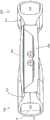
图1A和1B示出了示例性可调节人工晶状体。1A and 1B illustrate an exemplary accommodating intraocular lens.
图1C示出了图1A和1B的可调节人工晶状体的截面图。Figure 1C shows a cross-sectional view of the accommodating intraocular lens of Figures 1A and 1B.
图1D是可调节人工晶状体的示例性后部元件的俯视图。Figure ID is a top view of an exemplary posterior element of an accommodating intraocular lens.
图1E是可调节人工晶状体的示例性光学部分的截面组装图。Figure IE is a cross-sectional assembled view of an exemplary optical portion of an accommodating intraocular lens.
图1F和1G示出了示例性襻。Exemplary haptics are shown in FIGS. 1F and 1G.
图1H示出了光学部分与襻之间的示例性联接。FIG. 1H shows an exemplary coupling between the optic and the haptics.
图2A、2B和2C示出了示例性襻。2A, 2B and 2C illustrate exemplary haptics.
图2D、2E和2F图示了图2A的襻的截面图。2D, 2E, and 2F illustrate cross-sectional views of the haptics of FIG. 2A.
图2G示出了图2A-2C的襻的第一端部中的开口。Figure 2G shows an opening in the first end of the haptic of Figures 2A-2C.
图3示出了可调节人工晶状体的示例性直径。Figure 3 shows exemplary diameters of an adjustable intraocular lens.
图4示出了示例性襻。Figure 4 shows an exemplary haptic.
图5A和图5B示出了响应于示例性力的示例性襻的变形。5A and 5B illustrate deformation of an exemplary haptic in response to an exemplary force.
图6示出了示例性襻中的示例性流体开口。FIG. 6 shows an exemplary fluid opening in an exemplary haptic.
图7示出了示例性襻中的示例性流体开口。FIG. 7 shows an exemplary fluid opening in an exemplary haptic.
图8示出了示例性可调节人工晶状体的截面图。8 shows a cross-sectional view of an exemplary accommodating intraocular lens.
图9示出了具有较短襻的示例性可调节人工晶状体的截面图。9 shows a cross-sectional view of an exemplary accommodating intraocular lens with shorter haptics.
图10示出了具有与周边部分对中的光学部的示例性可调节人工晶状体的截面图。10 shows a cross-sectional view of an exemplary accommodating intraocular lens with an optic centered with a peripheral portion.
图11是示例性襻。Figure 11 is an exemplary haptic.
图12示出了示例性光学部分。Figure 12 shows an exemplary optical section.
图13示出了示例性襻的一部分。Figure 13 shows a portion of an exemplary haptic.
图14示出了示例性IOL。Figure 14 shows an exemplary IOL.
图15示出了示例性IOL。Figure 15 shows an exemplary IOL.
图16示出了示例性IOL。Figure 16 shows an exemplary IOL.
图17示出了示例性IOL的俯视图。17 shows a top view of an exemplary IOL.
图18示出了示例性光学部分。Figure 18 shows an exemplary optical section.
图19示出了示例性IOL的截面图。19 shows a cross-sectional view of an exemplary IOL.
图20示出了示例性IOL的俯视图。20 shows a top view of an exemplary IOL.
图21示出了示例性IOL的截面图。21 shows a cross-sectional view of an exemplary IOL.
图22示出了示例性IOL的俯视图。22 shows a top view of an exemplary IOL.
图23A示出了示例性IOL的俯视图。23A shows a top view of an exemplary IOL.
图23B示出了示例性IOL的截面图。23B shows a cross-sectional view of an exemplary IOL.
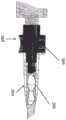
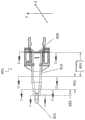
图24是内部装载有IOL的盒的截面图。24 is a cross-sectional view of a cartridge with an IOL loaded inside.
图25A、图25B、图25C示出了输送过程中的排气方法。Figures 25A, 25B, and 25C illustrate a method of venting during delivery.
图26A、26B和26C示出了通过支撑管从注射器行进的粘弹性流体。Figures 26A, 26B and 26C show viscoelastic fluid traveling from a syringe through a support tube.
图27是可用于将人工晶状体输送到眼内的示例性盒的俯视图。Figure 27 is a top view of an exemplary cassette that can be used to deliver an intraocular lens into the eye.
图28A、28B、28C和28D示出了图27中的盒的示例性内部横截面。28A, 28B, 28C, and 28D illustrate exemplary interior cross-sections of the cartridge of FIG. 27. FIG.
具体实施方式Detailed ways
本公开总体上涉及可调节人工晶状体。在一些实施例中,本文所述的可调节人工晶状体适于定位在其中天然晶状体已被移除的天然囊袋内。在这些实施例中,周边非光学部分(即,非专门适用于将光聚焦在视网膜上的部分)适于响应由于睫状肌放松和收缩而导致的囊袋形变。响应是周边部分的变形,其导致流体在周边部分和光学部分之间移动,以改变人工晶状体的光学参数(例如,度数)。The present disclosure generally relates to accommodating intraocular lenses. In some embodiments, the accommodating intraocular lenses described herein are adapted to be positioned within a native capsular bag from which the native lens has been removed. In these embodiments, the peripheral non-optical portion (ie, the portion not exclusively adapted to focus light on the retina) is adapted to respond to capsular bag deformation due to ciliary muscle relaxation and contraction. The response is a deformation of the peripheral portion, which causes fluid to move between the peripheral portion and the optic portion to change the optical parameters (eg, power) of the intraocular lens.
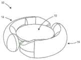
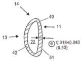
图1A是示出可调节人工晶状体10的俯视图,其包括光学部分12和周边部分,在该实施例中该周边部分包括联接到光学部分12并且从光学部分12在周边延伸的第一和第二襻14。光学部分12适于折射进入视网膜的光。襻14被构造成接合囊袋并适于响应于与睫状肌相关的囊袋形变而变形。图1B是人工晶状体10的透视图,示出了光学部分12和联接到光学部分12的襻14。1A is a top view showing an adjustable
襻与光学部分流体连通。每个襻具有与光学部分中的光学腔室流体连通的流体腔室。襻由可变形材料形成,适于接合囊袋并响应于睫状肌相关的囊袋形变而变形。当襻变形时襻流体腔室的体积改变,导致设置在襻流体腔室和光学流体腔室中的流体从襻流体腔室移入光学流体腔室,或者从光学流体移入襻流体腔室。当襻流体腔室的体积减小时,流体移入光学流体腔室。当襻流体腔室的体积增加时,流体从光学流体腔室移入襻流体腔室。流体流入和流出光学流体腔室改变了光学部分的构造和人工晶状体的度数。The haptics are in fluid communication with the optical portion. Each haptic has a fluid chamber in fluid communication with an optical chamber in the optical portion. The haptics are formed of a deformable material adapted to engage the capsular bag and deform in response to ciliary muscle-related capsular bag deformation. The volume of the haptic fluid chamber changes as the haptic deforms, causing fluid disposed in the haptic fluid chamber and the optical fluid chamber to move from the haptic fluid chamber into the optical fluid chamber, or from the optical fluid into the haptic fluid chamber. When the volume of the haptic fluid chamber decreases, fluid moves into the optical fluid chamber. As the volume of the haptic fluid chamber increases, fluid moves from the optical fluid chamber into the haptic fluid chamber. The flow of fluid into and out of the optical fluid chamber changes the configuration of the optic and the power of the IOL.
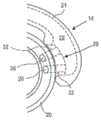
图1C是沿图1A中指示的截面A-A的侧面截面图。光学部分12包括可变形的前部元件18,所述可变形的前部元件18固定到可变形的后部元件20。每个襻14包括流体腔室22,所述流体腔室22与光学部分12中的光学流体腔室24流体连通。图1C的截面图中仅示出了(虽然不明显)图中左侧的襻14和光学部分12之间的联接。图中左侧的襻流体腔室22被示出为经由形成于后部元件20中的两个孔26与光学流体腔室24流体连通。图1C中右侧的襻14经由也形成在后部元件中的两个附加的孔(未示出)与光学腔室24流体连通,该孔与所示出的孔大致成180度。FIG. 1C is a side cross-sectional view along section A-A indicated in FIG. 1A . The
图1D是后部元件20(前部元件18和襻元件14未示出)的俯视图。后部元件20包括其中形成通道32的支撑物部分29。通道32提供光学部分12和襻14之间的流体连通。孔26设置在通道32的一端。因此光学流体腔室24经由两个流体通道与单个襻流体连通。如下所述,支撑物部分29的构造和尺寸被设置为设置在形成于襻14中的开口内,其限定襻流体腔室的一端。每个支撑物部分29包括形成在其中的两个通道。第一支撑物中的第一通道与第二支撑物中的第一通道对准。第一支撑物中的第二通道与第二支撑物中的第二通道对准。Figure ID is a top view of the rear element 20 (
在每个支撑物中具有两个通道而不是一个通道具有示例性优点。具有两个通道而不是一个通道的设计有助于在组装过程中保持尺寸稳定性,这在装配柔性和薄型部件时会很重要。此外,通过实验观察到,一些单通道设计可能无法在整个调节范围内提供足够的光学质量。特别是,在某些单通道设计中可能会发生晶状体像散,特别是在人工晶状体被调节时。发现本文描述的双通道支撑物设计可以帮助减少像散或像散的可能性,特别是在晶状体被调节时。在这些实施例中像散减小,因为支撑物的刚度由于两个通道之间的肋部增加。由于通道中的压力变化,额外的刚度导致较小的挠曲。由于通道中的压力变化导致的较小挠曲导致较少的像散。在一些实施例中,通道的直径在约0.4mm和约0.6mm之间。在一些实施例中,通道的直径为约0.5mm。在一些实施例中,孔之间的距离为约0.1mm至约1.0mm。There are exemplary advantages to having two channels in each support instead of one. A design with two channels instead of one helps maintain dimensional stability during assembly, which can be important when assembling flexible and thin parts. Furthermore, it has been observed experimentally that some single-channel designs may not provide sufficient optical quality over the entire tuning range. In particular, lens astigmatism can occur in some single-channel designs, especially when the intraocular lens is accommodated. The dual channel strut design described herein has been found to help reduce astigmatism or the likelihood of astigmatism, especially when the lens is accommodating. Astigmatism is reduced in these embodiments because the stiffness of the support is increased due to the ribs between the two channels. The extra stiffness results in less deflection due to pressure changes in the channel. Less deflection due to pressure changes in the channel results in less astigmatism. In some embodiments, the diameter of the channel is between about 0.4 mm and about 0.6 mm. In some embodiments, the diameter of the channel is about 0.5 mm. In some embodiments, the distance between the holes is about 0.1 mm to about 1.0 mm.
图1E是沿光学部分12的截面A-A的侧视组装图,其包括前部元件18和后部元件20(为了清楚起见未示出襻)。通过将流体通道32包括在后部元件20中,后部元件20需要具有足够的结构,通道32可以通过该结构形成。支撑物部分29提供其中可以形成通道32的结构。在其最外周部分处,后部元件20在前后方向上比前部元件18高。在替代实施例中,通道可形成在前部元件18中而不是后部元件20中。前部元件会包括支撑物部分29或其他类似结构以提供其中可形成通道的结构。在这些替代实施例中,后部元件可以与前部元件18类似地形成。1E is a side assembled view along section A-A of
如图1E所示,后部元件20在周边表面28处固定到前部元件18,周边表面28围绕后部元件20的周边延伸并且是平坦表面。元件18和20可以使用已知的生物相容性粘合剂固定在一起。前部元件18和后部元件20也可以由一种材料形成以免除将两个元件固定在一起的需要。在一些实施例中,前部元件18和后部元件20彼此固定的区域的直径为约5.4mm至约6mm。As shown in Figure IE, the
在一些实施例中,(沿前-后方向测量的)前部元件18的厚度沿着光轴(图1C中的“OA”)处的厚度大于周边处的厚度。在一些实施例中,厚度沿着光轴从周边向最厚部分连续增加。In some embodiments, the thickness of the front element 18 (measured in the anterior-posterior direction) is greater along the optical axis ("OA" in Figure 1C) than at the periphery. In some embodiments, the thickness increases continuously along the optical axis from the periphery to the thickest portion.
在一些实施例中,从沿着光轴的位置朝向图1C中标识的中心区域“CR”的边缘,后部元件20的厚度减小。如图1C所示,从中心区域CR朝向周边径向向外,厚度再次增大。在一些特定实施例中,中心区域CR的直径为约3.75mm。孔形成在斜面30中。In some embodiments, the thickness of the
在一些实施例中,后部元件20沿着光轴的厚度在约0.45mm和约0.55mm之间,并且在后部元件20的周边处的厚度在约1.0mm和约1.3之间。In some embodiments, the thickness of the
在一些实施例中,后部元件20沿着光轴的厚度为约0.5mm,后部元件20的周边处的厚度为约1.14mm。In some embodiments, the thickness of the
在一些实施例中,前部元件18沿着光轴的厚度在约0.45mm至约0.55mm之间,在一些实施例中在约0.50mm至约0.52mm之间。在一些实施例中,前部元件18的周边处的厚度在约0.15mm和约0.4mm之间,在一些实施例中在约0.19mm和约0.38mm之间。In some embodiments, the thickness of the
在一个特定实施例中,前部元件18沿着光轴的厚度为约0.52mm,并且前部元件18的周边的厚度为约0.38mm,后部元件20沿着光轴的厚度为约0.5mm,后部元件20的周边处的厚度为约1.14mm。In one particular embodiment, the thickness of the
在一个特定实施例中,前部元件18沿着光轴的厚度为约0.5mm,前部元件18的周边的厚度为约0.3mm,并且后部元件20沿着光轴的厚度为约0.5mm,后部元件20的周边处的厚度为约1.14mm。In one particular embodiment, the thickness of the
在一个特定实施例中,前部元件18沿着光轴的厚度为约0.51mm,前部元件18的周边厚度为约0.24mm,并且后部元件20沿着光轴的厚度为约0.5mm,后部元件20的周边处的厚度为约1.14mm。In one particular embodiment, the thickness of the
在一个特定实施例中,前部元件18沿着光轴的厚度为约0.52mm,前部元件18的周边厚度为约0.19mm,并且后部元件20沿着光轴的厚度为约0.5mm,后部元件20的周边处的厚度为约1.14mm。In one particular embodiment, the thickness of the
光学部分适于在整个调节期间保持光学质量。这确保了当可调节人工晶状体在非调节构型和调节构型之间过渡时,光学部分保持光学质量。许多因素有助于本文中可调节人工晶状体的这种有益特征。这些因素包括周边区域(在这里,前部元件18固定到后部元件20)、光学部分的中央区域CR内部的前部元件18和后部元件20的形状轮廓(参见图1C)、以及前部元件18和后部元件20的厚度轮廓。这些影响因素确保前部元件和后部元件两者以这样的方式弯曲,以便保持必要的形状以在一定范围的光强度(optical power)上保持光学质量。The optical section is adapted to maintain optical quality throughout the adjustment period. This ensures that the optic maintains optical quality when the accommodating IOL transitions between the non-accommodating and accommodating configurations. A number of factors contribute to this beneficial feature of the accommodating intraocular lenses herein. These factors include the peripheral area (where the
图1F示出了来自人工晶状体10的一个襻14(为了清楚起见未示出光学部分12和第二襻)。襻14包括适于面向悬韧带的方向的径向外部13和面向光学部件(未示出)的周边的径向内部11。襻14包括第一端部区域17和第二端部区域19,其中第一端部区域17固定到光学部分12,第二端部区域19是闭合的。襻14还包括第一端部区域17中的开口15,其提供与襻的流体连通。在该实施例中,开口15的尺寸和构造设置为在其中接收光学部分12的支撑物部分29。Figure IF shows one haptic 14 from intraocular lens 10 (
图1G是襻14中的开口15的特写视图,其适于在其中接收支撑物部分29。开口15具有弯曲表面33和35,其被成形为与光学支撑物29上的弯曲表面配合。表面31围绕开口15并且提供可以固定光学部的对应表面的表面。FIG. 1G is a close-up view of opening 15 in haptic 14 adapted to receive
图1H是设置在襻14中的开口15内的后部元件20(为清楚起见未示出光学部的前部元件)的支撑物部分29(以虚线示出)的俯视特写视图。通道32以虚线示出。襻14包括由内表面21限定的流体腔室22。在襻14变形时,流体在光学流体腔室和襻流体腔室22之间通过通道32移动。FIG. 1H is a top close-up view of the support portion 29 (shown in phantom) of the rear element 20 (the front element of the optic is not shown for clarity) disposed within the
图2A是示出了图1A-1H中所示的一个襻14的俯视图。未示出光学部分和第二襻。沿着襻标出了四个截面A-D。图2B是襻14的侧视图,示出了开口15和闭合端部19。图2C是襻14的侧视图,示出了径向外部13和闭合端部19。Figure 2A is a top view showing one of the
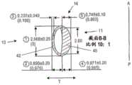
图2D是沿图2A中所示的截面A-A的横截面图。在图2A所示的四个截面中,截面A-A是最接近闭合端部19的截面。径向内部11和径向外部13被标出。还示出了由表面21限定的流体通道22。在该截面中,径向内部40在径向上比径向外部42更厚(在“T”方向上)。内部40提供沿着前后方向的襻刚度,其更加可预测性地使囊在前后方向上形变。径向内部40具有最大厚度尺寸41,其在该横截面中沿着对称轴。襻14的外表面具有大致椭圆形的构造,其中沿前后方向(“A-P”)的最大高度尺寸大于最大厚度尺寸(在“T”方向上测得)。流体腔室22具有大致D形构造,其中径向内壁43比径向外壁45弯曲较少(但不是完美线性)。径向外部42接合悬韧带附接到其上的囊袋,而较厚的径向部分40邻近光学部设置。Figure 2D is a cross-sectional view along section A-A shown in Figure 2A. Of the four sections shown in FIG. 2A , section A-A is the section closest to the
图2E示出了图2A中所示的截面B-B。截面B-B与截面A-A基本相同,图2E提供了两截面的示例性尺寸。径向内部40沿着中线(沿径向“T”)具有约0.75mm的最大厚度。径向外部42沿着中线具有约0.24mm的厚度。流体腔室22具有约0.88mm的厚度。襻14沿中线的厚度为约1.87mm。襻在前后方向的高度为约2.97mm。流体腔室的高度为约2.60mm。在该实施例中,径向内部40的厚度约为径向外部42的厚度的3倍。在一些实施例中,径向内部40的厚度约为径向外部42的厚度的2倍。在一些实施例中,径向内部40的厚度是径向外部42的厚度的约2至约3倍。在一些实施例中,径向内部40的厚度是径向外部42的厚度的约1至约2倍。Figure 2E shows the section B-B shown in Figure 2A. Section B-B is substantially the same as section A-A, and Figure 2E provides exemplary dimensions for both sections. The radially
流体腔室22设置在襻14的径向外部中。在该截面中的襻14的基本整个径向内部区域是散状材料。由于流体腔室22由表面43和45限定(参见图2D),所以流体腔室22的定位和尺寸取决于径向内部40和径向外部42的厚度。The
图2F示出了图1A中所示的截面C-C。尽管在截面C-C中径向内部40比径向外部42略厚,不过,在截面C-C中,径向内部40的厚度不如截面A-A和B-B中的径向内部40厚。在该特定实施例中,截面C-C中径向内部40为约0.32mm。径向外部42的厚度与截面A-A和B-B中的径向外部厚度约相同,为约0.24mm。襻14的外表面的构造与截面A-A和截面B-B中的外表面不同。在截面C-C中,襻51的径向内部外表面比截面A-A和截面B-B中的更线性,使得截面C-C中的襻的外表面呈大致D形。在截面C-C中,流体腔室22具有大致的D形,如在截面A-A和截面B-B中那样。截面C-C中的襻具有与截面A-A和截面B-B中的流体腔室构造基本相同的流体腔室构造,但其外表面的构造不同于截面A-A和截面B-B中襻14的外表面的构造。Figure 2F shows the section C-C shown in Figure 1A. Although radially
截面C-C中较薄的径向内部40还形成了图1A中所示的进入通路23。光学部分12和襻14之间的这个空间允许医师在手术过程中将一个或多个冲洗和/或吸气装置插入空间23中并施以抽吸以去除可用于将人工晶状体输送到眼睛中的粘弹性流体。通路23也可以是沿襻长度的任何地方,并且可以有多于一条的通路23。本申请通过引用并入了从美国公开第2008/0306588号图23和24中公开的内容及其文本描述,其包括襻中的多个通路。The thinner radial
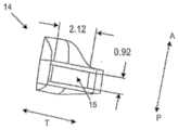
图2G示出了沿图2A的截面D-D的视图。襻14包括其中的开口15,其适于如本文所述从光学部分接收支撑物。该实施例中的开口15的高度为约0.92mm。开口的宽度或厚度为约2.12mm。Figure 2G shows a view along section D-D of Figure 2A.
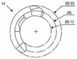
图3示出了光学部分12(未示出)和周边部分的相对直径,其包括两个襻14(仅示出了一个襻)。在该实施例中,光学部具有约6.1mm的直径,而包括周边部分的整个可调节人工晶状体具有约9.95mm的直径。所提供的尺寸并非旨在严格限制。Figure 3 shows the relative diameters of the optic portion 12 (not shown) and the peripheral portion, which includes two haptics 14 (only one is shown). In this embodiment, the optic has a diameter of about 6.1 mm, and the entire accommodating intraocular lens, including the peripheral portion, has a diameter of about 9.95 mm. Dimensions provided are not intended to be strictly limiting.
图4是襻14的俯视图,示出了襻14围绕光学部约175度角度的张角(即大致180度)。为了清楚起见未示出光学部分。因此,这两个襻各自围绕光学部有约180度角度的张角。示出了襻14的第一区域61有约118度的示例性角度的张角。这是襻14的径向最外部分,适于接合囊袋,并且适于对囊形状变化最具响应性。区域61可以被认为是襻14的最具响应性部分。FIG. 4 is a top view of the haptic 14 showing an angle of opening of the haptic 14 about a 175 degree angle (ie, approximately 180 degrees) about the optic. The optics are not shown for clarity. Thus, the two haptics each have an opening angle of about 180 degrees around the optic. The
截面A-A和B-B之间的角度,被认为是襻的更硬的径向内部的边界,是约40度。襻14的刚硬径向内部直接邻近光学部的周边定位。所提供的尺寸和角度并非旨在严格限制。The angle between sections A-A and B-B, considered to be the boundary of the stiffer radially inner part of the haptic, is about 40 degrees. The rigid radially inner portion of the
图5A和图5B示出了在天然晶状体已经从囊袋(“CB”)移除后,定位在囊袋(“CB”)中的可调节人工晶状体10的一部分。每个图中的前部方向在顶部,而后部方向在底部。相对于图5B中所示的高度数或被调节的构造,图5A示出了低度数或不被调节的构造的可调节人工晶状体。Figures 5A and 5B show a portion of the accommodating
弹性囊袋“CB”连接到悬韧带“Z”,其与睫状肌“CM”连接。当睫状肌放松时,如图5A所示,悬韧带被拉伸。由于囊袋与悬韧带之间的总体赤道连接位置,径向向外的力“R”导致该拉伸以大致径向向外的方向拉动囊袋。悬韧带拉伸导致囊袋的总体伸长并变薄。当天然晶状体仍然存在于囊袋中时,天然晶状体变得更平坦(在前后方向上)并且在径向方向上更高,这使得晶状体有更小的度数。如图5A所示,睫状肌的放松提供了远视力。然而,当睫状肌收缩时,就像眼睛试图聚焦在近处物体时发生的那样,肌肉的径向内部径向向内移动,导致悬韧带松弛。这在图5B中示出。悬韧带中的松弛使得囊袋可以朝向通常更弯曲的构型转变,其中前表面具有比在非调节构型中更大的曲率,从而提供更大的度数并允许眼睛聚焦在近处物体上。这通常被称为“调节”,并且晶状体被称为处于“调节的”构型。The elastic capsular bag "CB" is attached to the suspensory ligament "Z", which is attached to the ciliary muscle "CM". When the ciliary muscle relaxes, as shown in Figure 5A, the suspensory ligament is stretched. The radially outward force "R" causes this stretch to pull the capsular bag in a generally radially outward direction due to the general equatorial connection location between the capsular bag and the suspensory ligament. Suspension stretching results in general elongation and thinning of the capsular bag. While the natural lens is still in the capsular bag, the natural lens becomes flatter (in the anterior-posterior direction) and higher in the radial direction, which results in a smaller power of the lens. As shown in Figure 5A, relaxation of the ciliary muscle provided distance vision. However, when the ciliary muscle contracts, as happens when the eye tries to focus on a near object, the radially inner portion of the muscle moves radially inward, causing the suspensory ligament to relax. This is shown in Figure 5B. Relaxation in the suspensory ligament allows the capsular bag to transition toward a generally more curved configuration, where the anterior surface has greater curvature than in the non-accommodating configuration, providing greater power and allowing the eye to focus on near objects. This is often referred to as "accommodation" and the lens is said to be in the "accommodated" configuration.
在图5A和图5B中示出的襻14的截面A-A(其与截面B-B相同)中,径向内部40包括较厚的散状材料,其在前后方向上为襻14提供硬度。当袋囊力沿前后方向施加到襻时,由于其硬度,内部40以更可重复且可预测的方式变形,使得晶状体的基础状态更可预测。此外,由于其内部更硬,襻以可重复的方式在前后方向上使囊变形。此外,由于襻沿襻的长度较不灵活,所以可调节人工晶状体的基础状态更容易预测,因为沿着襻长度的弯曲是流体可以移动到光学部中的一种方式(并且由此改变晶状体的度数)。用更硬的内部实现的额外的优点在于,由于内部中的额外体积,襻对于诸如扭矩和展开的其他力更刚硬。In section A-A of haptic 14 shown in FIGS. 5A and 5B (which is the same as section B-B), radially
径向外部42是襻的这样一部分,即,该部分直接接合连接到悬韧带的囊袋的部分。襻的外部42适于响应当悬韧带放松和拉伸时大致径向施加的囊变形力“R”。这允许襻响应于睫状肌相关力(即,囊收缩和放松)而变形,使得流体将响应于睫状肌放松和收缩而在襻和光学部之间流动。这在图5B中示出。当睫状肌收缩时(图5B),弹性囊袋的周边区域形变并在襻14的径向外部42上施加径向向内的力“R”。径向外部42适于响应于该囊形变而变形。变形减小了流体通道22的体积,其迫使流体从襻腔室22进入光学腔室24。这增加了光学腔室42中的流体压力。流体压力的增加导致柔性前部元件18和柔性后部元件20变形,增加了曲率,从而增加人工晶状体的度数。The radially
襻适于在前后方向上比在径向方向上更硬。在该实施例中,襻14的径向外部42在径向方向上比更硬的内部40在前后方向上更柔性(即,较不刚硬)。这是由于外部42和内部部分40的相对厚度引起的。因而襻适于响应于沿前后方向的力比在径向方向上的力更少地变形。这也导致,比起响应于沿径向方向的力移入光学部,更少的流体响应于沿前后方向的力从襻移入光学部中。由于其较硬的径向内部,襻也将以更可预测和可重复的方式变形。The haptics are adapted to be stiffer in the anterior-posterior direction than in the radial direction. In this embodiment, the radially
因此,周边部分对囊袋在径向方向上形变比对囊袋在前后方向上形变更敏感。襻适于在径向上比在前后方向上更大程度地变形。因此,本文的公开内容包括对沿第一轴的囊力不太敏感但对沿第二轴的力更敏感的周边部分。在上面的示例中,周边部分沿着后前轴不太敏感,在径向轴上更敏感。Therefore, the peripheral portion is more sensitive to the deformation of the capsular bag in the radial direction than to the deformation of the capsular bag in the front-to-back direction. The haptics are adapted to deform to a greater extent in the radial direction than in the front-to-rear direction. Accordingly, the disclosure herein includes peripheral portions that are less sensitive to bladder forces along a first axis but more sensitive to forces along a second axis. In the example above, the peripheral portion is less sensitive along the rear front axis and more sensitive on the radial axis.
上述周边部分的示例性益处在于它们以可重复的方式使囊袋形变并且在调节期间仍保持对径向力的高度敏感性。上述周边部分在前后方向上比在径向方向上更硬。An exemplary benefit of the peripheral portions described above is that they deform the bladder in a repeatable manner and remain highly sensitive to radial forces during adjustment. The aforementioned peripheral portion is stiffer in the front-rear direction than in the radial direction.
在可调节人工晶状体定位在囊袋中并且囊袋大致经历愈合反应之后,在前后方向上的囊力的另一个示例是在周边部分上的囊力。愈合反应通常在前后方向上引起襻上的收缩力,在图5A中由力“A”表示。在2010年1月11日提交的美国申请第12/685,531号中描述了这些和其他后植入物,例如非可调节相关的囊袋形变力,其通过引用并入本文。例如,囊袋尺寸因患者不同而有变化,这也在2010年1月11日提交的美国申请第12/685,531号中详细描述。当人工晶状体位于囊袋内时,囊和人工晶状体的尺寸差异可以使力在前后方向上施加在人工晶状体的一个或多个部分上。Another example of the capsular force in the anterior-posterior direction is the capsular force on the peripheral portion after the adjustable intraocular lens is positioned in the capsular bag and the capsular bag substantially undergoes a healing response. The healing response typically induces a contractile force on the haptic in the anterior-posterior direction, represented by force "A" in Figure 5A. These and other posterior implants, such as non-adjustable relative capsular bag deformation forces, are described in US Application No. 12/685,531, filed January 11, 2010, which is incorporated herein by reference. For example, the size of the capsular bag varies from patient to patient, which is also described in detail in US Application No. 12/685,531, filed January 11, 2010. The difference in size of the capsule and the intraocular lens can cause forces to be exerted on one or more portions of the intraocular lens in an anterior-posterior direction when the intraocular lens is in the capsular bag.
在前后方向上的囊愈合力的示例中,力可以在任何调节发生之前使可变形的襻变形。该变形改变了襻流体腔室的体积,导致流体在光学流体腔室和襻流体腔室之间流动。这在某些情况下会不合需要地改变晶状体的基础度数。例如,流体可以在囊愈合时被迫进入光学部中,从而增加可调节人工晶状体的度数,并且使可调节人工晶状体产生永久性近视偏移。流体也可能被挤出光学部并进入襻,从而降低了可调节人工晶状体的度数。In the example of capsular healing force in the anterior-posterior direction, the force may deform the deformable haptics before any adjustment occurs. This deformation changes the volume of the haptic fluid chamber, causing fluid to flow between the optical fluid chamber and the haptic fluid chamber. This can undesirably alter the basal power of the lens in some cases. For example, fluid can be forced into the optic as the capsule heals, thereby increasing the power of the accommodating IOL and creating a permanent myopic shift in the accommodating IOL. Fluid may also be pushed out of the optic and into the haptics, reducing the power of the accommodating IOL.
如本文所使用的,“径向”不必限于与前后平面精确地正交,而是包括与前后平面成45度的平面。As used herein, "radial" is not necessarily limited to being exactly orthogonal to the anterior and posterior planes, but includes planes that are 45 degrees from the anterior and posterior planes.
在2010年1月11日提交的美国申请第12/685,531号和2011年2月23日提交的美国申请第13/033,474号中描述了示例性流体,两者均通过引用并入本文。例如,流体可以是与前部和后部元件的聚合物材料折射率匹配或不匹配的硅油。当使用与光学部分的散状材料折射率匹配的流体时,整个光学部分作为单个晶状体,其外曲率随着光学部分中的流体压力的增加和减小而变化。Exemplary fluids are described in US Application Nos. 12/685,531, filed Jan. 11, 2010, and 13/033,474, filed Feb. 23, 2011, both of which are incorporated herein by reference. For example, the fluid may be a silicone oil that is index matched or mismatched to the polymeric material of the front and rear elements. When using a fluid that is index-matched to the bulk material of the optic, the entire optic acts as a single lens, the outer curvature of which varies with increasing and decreasing fluid pressure in the optic.
在上述图2A-2G中的实施例中,襻是在截面A-A、B-B和C-C中具有基本均匀组成的可变形聚合物材料。较硬的径向内部主体部分40归因于其厚度。在替代实施例中,径向内部主体部分具有与外部主体部分不同的组成,其中径向内部主体部分材料比径向外部主体部分的材料更硬。在这些替代实施例中,径向内部部分和径向外部部分的厚度可以相同。In the embodiments of Figures 2A-2G described above, the haptics are deformable polymeric materials of substantially uniform composition in cross-sections A-A, B-B, and C-C. The harder radially
图6示出了襻50,其与图2B所示的襻构造相同。径向外部54被标出。襻在襻的高度的一半处具有轴线“A”,或者可替代地,轴线A在前后方向上经过襻的高度的中点。其中设置有光学支撑物的开口52位于轴线A的后侧。在该实施例中,比起襻的最前部,光学部稍微靠近襻的最后部。也就是说,在该实施例中,光学部不在前后方向上与襻对中。Figure 6 shows a haptic 50, which is the same configuration as the haptic shown in Figure 2B. The radially
图7示出了可替代的襻60(光学部未示出),其中径向外部64被标出。襻60在襻的厚度的一半处包括轴线“A”,或者可替代地,轴线A在前后方向上经过襻的高度的中点。开口62关于轴线A对称,经过开口62的中点的轴线与轴线A对准。另外,轴线A是襻60的对称轴线。襻沿着轴线A的对称可以提高模制较低应力部件的能力。图8示出了人工晶状体70的一个实施例,其中光学部72联接到两个襻60,这两个襻是图7所示的襻。光学部进一步沿向前方向放置,在该实施例中,在该向前方向中不沿着襻的中线。在这个实施例中,光学部72沿前后方向与襻对中。襻60的横截面A-A、B-B和C-C与上述其他实施例中所示的那些相同,但是襻也可以具有任何替代构造。Figure 7 shows an alternative haptic 60 (optics not shown) with radially
图9示出了包括光学部82和两个襻84的人工晶状体80。该光学部与本文所述的光学部分相同。襻84在前后方向上不如襻60、襻50或襻14那样高。在示例性实施例中,襻84的高度在约2.0mm和约3.5mm之间,并且在一些实施例中它们是约2.8mm高。人工晶状体80可以被认为是尺寸“小”的可调节人工晶状体,用于具有低于特定阈值尺寸的囊袋的患者。后部元件86的后表面比襻84的最后部分90稍微更向后方设置。FIG. 9 shows an
图10示出了可调节人工晶状体98,其包括光学体100和周边非光学体,在该实施例中该周边非光学体包括襻160和180。光学体100可以与襻160和180中的一个或两个流体连通,并且流体响应于睫状肌运动的光学部和襻之间的运动可以改变人工晶状体的度数。这里可以找到响应于襻变形的流体驱动调节的这种基本过程。光学体100包括固定到后部元件140的前部元件120,一起限定与襻中的襻流体腔室170和190连通的光学流体腔室。本公开中的构件的“高度”是在前后方向上测量的。光学体100具有沿光轴在前后方向测量的最大高度“H1”尺寸。襻160和180具有在平行于光轴的前后方向上测量的最大高度“H2”尺寸。光学体具有中心线B,垂直于光轴测量并经过H1的中点。襻也有中心线B,垂直于光轴测量并经过H2的中点。在该实施例中,中心线重合并且是相同的中心线B。换句话说,前部元件120的最前的表面或点与襻的最前的点或表面之间的距离和后部元件140的最后的表面或点与襻的最后的点或表面之间的距离相同。在一些实施例中,它们可以被认为是基本相同的线条,即使它们不重合,但彼此在空间上接近(例如,相距几个毫米)。图8中还显示了以襻为中心的光学部。FIG. 10 shows an accommodating
在该实施例中,光学部100相对于襻的位置可以提供一些益处。例如,在折叠和/或插入过程中,沿前后方向测量的居中(或基本上居中)的晶状体可以防止或减少一个或多个襻折叠到前部元件120或后部元件140上的可能性,这可能在光学体相对于襻没有基本居中时发生。例如,更靠近晶状体后侧的光学部可增加在变形、装载或植入期间襻(例如,襻自由端部)可折叠在光学部的前表面上的可能性。In this embodiment, the position of the optic 100 relative to the haptics may provide some benefits. For example, a centered (or substantially centered) lens, measured in the anterior-posterior direction, may prevent or reduce the likelihood of one or more haptics being folded onto the
使光学体100相对于周边体居中或大致居中的另一益处在于,当放置在眼睛中时,光学部更容易通过撕囊。当光学部更靠近晶状体的后侧时,它可能更难以旋入囊袋。Another benefit of centering or substantially centering the
另外的益处在于,与进一步在后方的光学部相比,来自人工晶状体的眩光减少。通过沿向前方向移动光学部(一旦植入后它将更接近虹膜),较少的光可以从光学部的径向外部周边边缘(即,与襻相邻的边缘表面)反射,从而减少来自边缘的眩光影响。An additional benefit is that glare from the intraocular lens is reduced compared to optics further behind. By moving the optic in the forward direction (which will be closer to the iris once implanted), less light can reflect from the radially outer peripheral edge of the optic (ie, the edge surface adjacent to the haptics), thereby reducing the Glare effect on edges.
在图10中的人工晶状体的一些实施例中,前部元件120可以具有在0.2mm与0.35mm之间的高度,诸如在0.25mm与0.30mm之间,诸如约0.28mm,并且后部元件140可以具有在0.36mm和0.50mm之间的高度,诸如在0.40mm和0.45mm之间,例如约0.43mm。In some embodiments of the intraocular lens in Figure 10, the
在插入之前,例如在制造期间,图10中所示的人工晶状体可以充满流体。在一些实施例中,人工晶状体具有小于15D,例如约13D的基础状态(在光学部中为零流体压力或其内部没有流体)。如本文所用的,约13D是指约10D至约15D的基础状态。通过具有约13D的基础状态,通常可能仅需要在一个方向上改变流体压力-更高。当人工晶状体的基础状态较高,例如约20D时,取决于期望的视力校正和人工晶状体的预期用途,可能需要改变为更高或更低的流体压力。通过具有较低的基础状态,只需要在一个方向上改变基础状态,晶状体状态的变化就变得更加可预测。The intraocular lens shown in Figure 10 may be filled with fluid prior to insertion, eg, during manufacture. In some embodiments, the intraocular lens has a basal state of less than 15D, eg, about 13D (zero fluid pressure in the optic or no fluid inside it). As used herein, about 13D refers to a basal state of about 10D to about 15D. By having a base state of about 13D, it may often only be necessary to change the fluid pressure in one direction - higher. When the basal state of the IOL is high, eg, about 20D, a change to higher or lower fluid pressure may be required depending on the desired vision correction and the intended use of the IOL. By having a lower basal state, the basal state only needs to be changed in one direction, and changes in the lens state become more predictable.
本公开的一个方面是可调节人工晶状体,其可选地由流体填充并且流体驱动,其在制造之后和在植入之前具有非球面光学表面。也就是说,人工晶状体被制造成具有非球面光学表面。当瞳孔完全扩张时,非球面光学表面可以避免球面像差。在制造具有非球面光学表面的人工晶状体时,特别是制造可调节、流体驱动的人工晶状体时可能存在挑战。One aspect of the present disclosure is an accommodating intraocular lens, optionally fluid-filled and fluid-driven, having an aspheric optical surface after manufacture and prior to implantation. That is, intraocular lenses are manufactured with aspheric optical surfaces. Aspheric optical surfaces avoid spherical aberration when the pupil is fully dilated. There can be challenges in fabricating intraocular lenses with aspheric optical surfaces, especially adjustable, fluid-actuated intraocular lenses.
在一些实施例中,可调节人工晶状体被制造成具有非球面前表面和/或非球面后表面。一种示例性方式(其中充满流体的可调节人工晶状体可以包括具有内置非球面性的前部或后部光学表面)是,在制造期间在流体填充之前形成具有球面构型的光学表面,然后在填充过程中在光学表面中形成非球面性。例如,在制造期间,前表面和后表面中的一个或两个可被制造成具有球面外部光学表面。然后可以将前表面固定到后表面。然后可以将一个或多个襻固定到光学部上。在一些实施例中,制造光学部,但是在填充之前,具有小于15D,例如约13D的基础状态(在光学部中为零流体压力或其内部没有流体)。如本文所用的,约13D是指约10D至约15D的基础状态。当流体被注入可调节人工晶状体(例如,经由隔膜)时,流体填充步骤可以增加光学部中的流体压力并使得光学部的前表面和/或后表面具有非球面构型。因此,本公开的一个方面是制造可调节人工晶状体的方法,其包括在插入之前形成具有流体填充状态的光学部,该光学部具有构建在一个或多个光学表面(例如前部光学表面)中的非球面性。制造方法可以包括制造光学部,其中光学表面在流体填充之前是球面的。In some embodiments, the accommodating intraocular lens is manufactured with an aspherical front surface and/or an aspherical back surface. One exemplary approach (wherein a fluid-filled accommodating IOL may include an anterior or posterior optical surface with built-in asphericity) is to form the optical surface with a spherical configuration prior to fluid filling during manufacturing, and then Asphericity is formed in the optical surface during filling. For example, during manufacture, one or both of the front and back surfaces may be fabricated with spherical outer optical surfaces. The front surface can then be secured to the rear surface. One or more haptics can then be secured to the optic. In some embodiments, the optic is fabricated, but prior to filling, with a base state of less than 15D, eg, about 13D (zero fluid pressure in the optic or no fluid inside it). As used herein, about 13D refers to a basal state of about 10D to about 15D. When fluid is injected into the accommodating intraocular lens (eg, via the septum), the fluid filling step may increase the fluid pressure in the optic and cause the anterior and/or posterior surfaces of the optic to have an aspheric configuration. Accordingly, one aspect of the present disclosure is a method of making an accommodating intraocular lens comprising forming an optic having a fluid-filled state prior to insertion, the optic having built into one or more optical surfaces (eg, anterior optical surface) asphericity. The fabrication method may include fabricating the optic, wherein the optical surface is spherical prior to fluid filling.
在整个不可调节或整个调节过程中,在光学部变形时,可能期望光学部的中央部分的至少一个表面中保持良好的光学质量。本公开的一个方面是光学部,该光学部在整个度数范围内在光学部的中心区域中具有非常可控的且稍微稳定的非球面量。这在本文可以称为光学部中心区域中的“有益的非球面性”。有益的非球面性包括具有表面像差的晶状体表面,所述表面像差被配置为补偿眼睛的光学系统中的球面像差,并且有助于保持光学质量。在调节和非调节期间,在全部或基本上全部的度数范围内保持有益的非球面性。在一些情况下,可以控制非球面性,使得整个晶状体系统的球面像差可以在整个度数范围内保持低(或零)。中心区域之外的光学区域可以具有更大、更不受控制的非球面量。It may be desirable to maintain good optical quality in at least one surface of the central portion of the optic when the optic is deformed throughout the non-adjustment or the entire adjustment process. One aspect of the present disclosure is an optic having a very controllable and somewhat stable amount of aspheric surface in the central region of the optic over the entire range of degrees. This may be referred to herein as "beneficial asphericity" in the central region of the optic. Beneficial asphericity includes a lens surface having surface aberrations configured to compensate for spherical aberration in the optical system of the eye and to help maintain optical quality. Beneficial asphericity is maintained over all or substantially all of the degree range during conditioning and non-conditioning. In some cases, asphericity can be controlled such that spherical aberration of the entire lens system can be kept low (or zero) over the entire power range. Optical regions outside the central region can have larger, less controlled amounts of asphericity.
在一些实施例中,光学部的中心区域或有益的非球面性区域的直径小于6.5mm,小于6.0mm,小于5.5mm,小于5.0mm,小于4.5mm,小于4.0mm,小于3.5mm,甚至小于3.0mm。在一些实施例中,中心区域具有3.5mm和5.5mm之间的直径。在一些实施例中,具有有益非球面性的光学部的中心区域的直径小于光学体直径的90%,小于85%,小于80%或小于75%。光学部的直径可以在4mm和8mm之间,例如在5mm和7mm之间。在一些实施例中,中心区域在4mm和5mm之间,并且光学直径在5mm和7mm之间。在一些实施例中,中心区域在4.25mm和4.75mm之间,并且光学直径在5.75mm和6.25mm之间。In some embodiments, the diameter of the central region or beneficial aspheric region of the optic is less than 6.5mm, less than 6.0mm, less than 5.5mm, less than 5.0mm, less than 4.5mm, less than 4.0mm, less than 3.5mm, or even less than 3.0mm. In some embodiments, the central region has a diameter of between 3.5mm and 5.5mm. In some embodiments, the diameter of the central region of the optic having beneficial asphericity is less than 90%, less than 85%, less than 80%, or less than 75% of the diameter of the optic body. The diameter of the optic may be between 4mm and 8mm, for example between 5mm and 7mm. In some embodiments, the central area is between 4mm and 5mm, and the optical diameter is between 5mm and 7mm. In some embodiments, the central area is between 4.25mm and 4.75mm and the optical diameter is between 5.75mm and 6.25mm.
前部元件和后部元件的构造可以影响在整个变形期间它们假定的构型,无论是在整个调节期间还是在非调节期间。在一些实施例中,前部元件和后部元件中的一个或两个被构形或被构造,使得光学部的中心区域具有有益的非球面性,其被控制并且对整个眼睛系统有益。在该实施例中,前部元件120以及较小程度的后部元件140被构造为使得前部元件120的前表面和后部元件140的后表面在调节期间在光学部的中心区域中保持受控的有益的非球面性。在该实施例中,有助于保持有益的非球面性的中心部分的构造的一个方面是,前部元件120和可选的后部元件140在中心处(例如在前部元件120的顶点处)在前部元件120的周边处具有更大的厚度(在本文中也称为“高度”)。有益于非球面性的构造的另一方面是,前部元件在内表面(后表面)上比在外表面(前表面)上更平坦。在调节期间,前部元件120的中心区域在中心陡峭(这增加了AIOL的度数),但是光学体保持其有益的非球面性,这至少部分归因于前部元件中心区域的相对较大的厚度。在其中将非球面性构建到前部元件中的示例性实施例中,在调节之前它也可以是非球面的,如下所述。The configuration of the front and rear elements can affect their assumed configuration throughout the deformation, whether during the entire adjustment period or during the non-adjustment period. In some embodiments, one or both of the anterior and posterior elements are shaped or constructed such that the central region of the optic has a beneficial asphericity that is controlled and beneficial to the entire ocular system. In this embodiment, the
前部和后部元件的厚度轮廓可以有助于光学元件在所有度数上都保持有益的非球面性,其中一个示例是前部和后部元件的厚度。The thickness profiles of the front and rear elements can help the optic maintain beneficial asphericity in all degrees, one example of which is the thickness of the front and rear elements.
图11示出了示例性襻,其可以是本文中的可调节人工晶状体中的任何一个的一部分或本文未描述的其他适当IOL的一部分。一个或两个襻可以如图11所示构造。图11中的襻被标记为“160”,但是应该理解的是,图11中的襻可以是人工晶状体的一部分,不同于图10所示那样。襻包括固定到光学体的外边缘的表面220。表面220是襻的径向内部表面,并且被构造为具有与光学部的外边缘基本相同的曲线(沿着襻的长度)的轻微弯曲,使得整个表面220与光学体外边缘表面交接。表面220具有相对于光学部的构造,使得表面的延伸不经过光学部的光轴。可以使用粘合剂将表面220固定到光学部外边缘表面。在该实施例中,襻和光学体之间的联接不包括设置在另一个中的通道、镗孔或孔中的襻和光学中的一个,如可以用于一些襻/光学联接设计那样,诸如在图1A-9中所示的实施例。下面描述这种设计的一些示例性优点。Figure 11 shows an exemplary haptic that may be part of any of the accommodating intraocular lenses herein or part of other suitable IOLs not described herein. One or both haptics can be configured as shown in FIG. 11 . The haptics in FIG. 11 are labeled "160", but it should be understood that the haptics in FIG. 11 may be part of an intraocular lens other than that shown in FIG. 10 . The haptics include a
图12示出了光学部100的透视图,其中为了清楚起见除去了襻。襻(未示出)的表面220固定到光学体100的前部元件120和后部元件140两者。大部分表面220与后部140交接,但表面220的一部分与前部元件120交接。这是因为光学体的外边缘大部分由后部元件140构成。在不同的光学构造中,比起后部元件,表面220可以固定到更多的前部元件。还要注意的是,表面220的高度H3(参见图11)基本上与光学体的外边缘的高度相同。Figure 12 shows a perspective view of the optic 100 with the haptics removed for clarity. The
襻160表面220具有第一端部区域230(见图11),其具有比第二端部区域250更大的表面的构造。表面220的端部区域230具有比表面220的端部区域250更大的表面积并且包括至少部分斜面B,如图13所示。端部区域230的宽度W1大于端部区域250的宽度W2。端部区域230的构造可以提供示例性益处。例如,作为将人工晶状体装载到输送装置和/或患者眼睛中的过程的一部分,襻160和180中的一个或两个可以相对于光学部“张开”。也就是说,通过将襻的自由端部170从光学体移开,可以从图10-14所示的静止自然构型中重新构造一个或两个襻。在张开过程中自由端部(和大部分襻)从光学部移开的程度可以变化。在一些装载方法中,两个襻中的一个可以基本张开,使得襻定向在光学部的后面或前方。在一些情况下,襻自由端部(即,襻的不直接联接到光学部的端部)从其在静止构型中指向的位置“指向”大致180度。一般而言,张开(一个或多个)襻导致襻和光学部之间的联接界面处的应力。光学部与襻之间的联接界面必须能够承受这些力,使得襻不会从光学部脱离。当张开襻时,在界面230的端部处的光学部/襻联接处会存在高应力位置,其更接近自由端部。因而端部区域230是襻/光学部界面最有可能失败的位置。端部区域230具有较大的表面积以及逐渐变细且倾斜的构造,用于分布施加的应力(或者在襻相对于光学部重新定向的任何时候的应力),并且防止襻从光学部脱离。The haptic 160
表面220的构造可以以许多方式改进,以在襻和光学部之间提供期望的接合。因而以这种方式接合襻和光学部(而不是将一个元件安装在另一个元件中)允许更多的界面构造,这提供了更多的设计灵活性。The configuration of
在图11中的襻的实施例中,流体孔240沿着襻的中线居中。中心线的定义方式与图10所示的相同。在襻侧视图中中心线通过襻高度(沿前后方向测量)的中点。In the embodiment of the haptic in Figure 11, the
襻的其他方面可与本文所述的相同,例如沿着襻的一部分的较厚的径向内壁厚度,以及一个或两个襻跟随光器件的周边从联接端到自由端部的曲率,并且襻的最前面的部分比光学部的最前面的部分更向前延伸。Other aspects of the haptics may be the same as described herein, such as the thicker radial inner wall thickness along a portion of the haptics, and the curvature of one or both haptics following the periphery of the light device from the coupling end to the free end, and the haptics The frontmost portion of the optic extends further forward than the frontmost portion of the optic.
后部元件140中具有与襻流体腔室170和190流体连通的两个流体通道210。后部元件140的外边缘中包括限定流体通道210的端部的两个孔。襻/光学界面(其可以是胶合)围绕后部元件140中的两个流体孔。在一些替代方案中,该光学部仅具有一个流体通道而不是两个。The
图13是襻160的另一视图,示出了光学界面表面220和其中的流体孔240的轻微弯曲。Figure 13 is another view of the
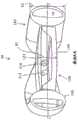
图14是从后侧观察的图10的人工晶状体的透视图。可以在后部元件140中看到流体通道210,其中两个与每个襻相关联。襻和光学部之间的界面也可以看到。图14显示了图10中所示的截面A-A。Fig. 14 is a perspective view of the intraocular lens of Fig. 10 viewed from the posterior side.
图15示出了来自图10的人工晶状体的其他视图,其中可以看到在光学部的外边缘和襻之间的间隙292以及光学部和襻之间的联接。Figure 15 shows another view of the intraocular lens from Figure 10, where the
在其中一个或多个襻在离散位置(而不是光学部周围的180度)粘附到光学体的一些实施例中,固化将襻固定到光学体的粘合剂的固化步骤可能导致材料在两个部件粘附的位置处收缩。离散位置处的这种收缩会导致晶状体中的畸变,例如像散。防止或减少畸变的程度可能是有益的或必要的。图16示出了替代的可调节人工晶状体300的分解透视图。图17示出了AIOL 300的俯视图。图18示出了AIOL 300的光学部301的透视图。图19是图17中示出的截面A-A的视图In some embodiments in which one or more haptics are adhered to the optic body at discrete locations (rather than 180 degrees around the optic), the curing step of curing the adhesive securing the haptics to the optic body may result in the material at two shrinks where the parts stick. Such contractions at discrete locations can lead to distortions in the lens, such as astigmatism. It may be beneficial or necessary to prevent or reduce the degree of distortion. FIG. 16 shows an exploded perspective view of an alternative accommodating
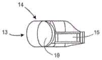
图16-18示出了示例性光学体301(参见图18)和襻310之间的示例性界面,其可以帮助减轻由于光学体和襻相固定的位置处的收缩引起的畸变。与诸如图10-15中的其他实施例相比,光学体301和襻310之间的界面径向远离光学体301(特别是光学表面)而重新定位。通过将界面(即可能收缩的位置)移动离开光学表面,可以减少固化步骤对光学表面造成的畸变量。襻310的联接区域311各自与光学突起部303接口接合,使得襻和突起部303之间的界面径向远离光学部的光学表面。这种类型的界面可以与非调节或可调节人工晶状体一起使用,但在该实施例中,该晶状体是可调节人工晶状体。FIGS. 16-18 illustrate an exemplary interface between an exemplary optical body 301 (see FIG. 18 ) and a haptic 310 that can help mitigate distortion due to shrinkage at locations where the optical body and haptic phase are fixed. In contrast to other embodiments such as in Figures 10-15, the interface between the
例如,可调节人工晶状体300可以包括光学体301(见图18)和襻310。在该实施例中,襻310与光学部310分开制造,然后固定到光学部310。襻310各自包括固定到光学部310的径向周边表面306的径向内部平坦表面312(在图16中仅标记一个)。在该实施例中,表面312是襻310的联接区域311的径向内部表面。例如,可使用粘合剂将表面312固定到光学部310的径向周边表面306。如上所述,将襻固定到光学部的过程可能影响光学部70的光学性能。例如,粘合剂的固化过程可能导致光学部301在两个离散位置处的收缩,因此可能导致人工晶状体的畸变和像差,例如像散。For example, the accommodating
在该实施例中,人工晶状体包括远离光学部301的后部元件304的周边表面309而径向向外延伸的两个突起部303。突起部303可以被认为是来自光学部的大致弯曲周边的突起部,如由外边缘表面309限定的。襻310可各自具有固定到突起部303的第一部分311和远离第一部分311设置的自由的第二部分315,其中每个襻的径向内部表面跟随光学部的径向外周边表面。在本公开中,突起部303在本文中也可被称为“平台”或“台”。In this embodiment, the intraocular lens includes two
突起部303可以是从光学部的周边表面309径向向外延伸10微米至1mm之间的突出区域,可选地延伸10微米至500微米之间。突起部303的径向周边表面306可以比光学部的周边表面309径向远离光学部的中心达10微米至1mm之间,可选地在10微米至500微米之间。例如,突起部303可以是从光学部的周边表面309径向向外延伸100微米至200微米之间的突出区域。突起部303的径向外周边表面305可以比光学部的周边表面309距距光学部的中心远100微米和200微米之间。超出上述范围的值也是可以的。突起部303可以使固定表面或联接表面远离光学部移动,以防止在固化光学部与襻之间的粘合剂过程中由于收缩引起的光学畸变。The
在一些实施例中,光学部在俯视图中具有圆形形状,并且光学部的径向外周边边缘309大致为圆形。当本文描述的突起部从光学体径向延伸出时,突起部可以延伸远离光学部的径向外部周边边缘的大致曲线。In some embodiments, the optic has a circular shape in top view, and the radially outer
在一些实施例中,人工晶状体的光学部和突起部303可以是单个整体。例如,突起部303可以被模制成光学部的一部分。在一些其他实施例中,突起部303可以例如通过胶合附接到光学部。In some embodiments, the optic and
在一些实施例中,光学部301包括后部元件和前部元件,可选地在其之间限定流体腔室,例如在上述实施例中那样。例如,突起部303可以是后部元件的一部分,因为后部具有较厚的周边。这些突出部分也可以是前部元件的一部分。又例如,突起部可以是光学部的后部元件和前部元件的一部分。In some embodiments, the optic 301 includes a rear element and a front element, optionally defining a fluid chamber therebetween, such as in the above-described embodiments. For example, the
突起部303的外表面306和襻310的内表面312都可以是平坦的,使得它们在对接接合处接口接合。例如,突起部303的径向外部周边表面306可以包括平坦表面,可选地完全平坦。襻310的径向内部表面312也可以包括平坦表面,可选地完全平坦。另一示例中,突起部303的径向外部周边表面306可以包括弯曲表面,可选地整个弯曲。襻310的径向内部表面312也可以包括弯曲表面,可选地整个弯曲。径向外部周边表面306的曲率可以与光学体的周边表面309的曲率相同,在一些实施例中可以大于或小于光学体的周边表面309的曲率。Both the
襻310可以包括如本文所述的周边流体腔室。突起部303可以包括至少一个流体通道308,并且可选地包括至少两个通道,与襻中的周边流体腔室流体连通。突出的突起部303可以为流体通道提供更高的稳定性,因为在突起部的位置处存在更多的光学材料。
通常,突起部可以设置在通过联接襻和光学部而制造的非调节(固定度数)人工晶状体上。例如,固定度数的人工晶状体(其中人工晶状体是具有单一度数(例如,PMMA材料)的非流体填充的光学体和两个襻)也可以包括从光学体的周边表面径向向外延伸的突起部。Typically, protrusions may be provided on a non-accommodating (fixed power) intraocular lens manufactured by coupling the haptics and optic. For example, fixed power intraocular lenses (where the intraocular lens is a non-fluid filled optic with a single power (eg, PMMA material) and two haptics) may also include protrusions extending radially outward from the peripheral surface of the optic body .
图16-19中的实施例还示出了可以结合到本文中的任何合适的光学部(例如图10中示出的光学部100)中的可替代的襻横截面构造(关于横截面参见图19)。襻310的高度H(沿前后方向测量)可以从2mm至2.5mm,可以是2.1mm至2.4mm。这可能小于其他人工晶状体的其他襻高度,例如3mm以上的高度。为襻提供2至2.5mm之间的高度可能是有益的,但不是必需的。根据患者的眼睛解剖结构的不同而有尺寸变化。例如,囊尺寸、或囊与虹膜后侧之间的距离存在变化。对于某些襻,襻和虹膜的后侧之间可能会有一些摩擦。即使有,也不会引起任何担忧。因此,仅仅在很谨慎的情况下,具有最小化这种摩擦的可能性的襻高度可能是有益的。The embodiments in Figures 16-19 also illustrate alternative haptic cross-sectional configurations that may be incorporated into any suitable optic herein (eg, optic 100 shown in Figure 10) (see Figures for cross-sections). 19). The height H (measured in the front-to-back direction) of the
襻310还包括在流体腔室316的径向内侧上的径向内壁部分313,其厚度“ti”大于腔室316的径向外侧上的襻壁的厚度“t0”。在一些实施例中,“ti”比“t0”大四至九倍。径向内壁部分313在本文中可以被称为“间隔件”。如图16所示,间隔件几乎沿着整个襻的长度,但不存在光学部和襻之间存在间隙的地方。如图所示,流体腔室316径向内壁比流体腔室316径向外壁更平坦。襻310是在经过光学部分的光轴的平面中具有横截面的襻的示例,其中襻流体腔室被设置在襻的径向外部中,并且其中襻的径向内部是非流体的。襻310是这样的襻示例,即,在经过光学部分的光轴的平面的截面中以及与通过襻的中点与光学部分的光轴正交的方向中,襻具有的径向内部流体腔室壁厚是径向外部流体腔室壁厚的4至10倍。襻310是这样的襻示例,即,在经过光学部分的光轴的平面的横截面中,襻具有的外表面关于经过周边部分并平行于光学部分的光轴的任何轴线不对称,并且其中在与经过襻中点的光学部分的光轴正交的方向上,襻具有的径向内部流体腔室壁厚大于径向外部流体腔室壁厚。襻310是这样的襻示例,即,在经过光学部分的光轴的平面的横截面中,襻具有沿前后方向测量的高度尺寸,其中周边部分的径向外半部中周边部分的最大高度大于周边部分的径向内半部中周边部分的最大高度。The haptic 310 also includes a radially
在一些实施例中,光学体的一个或多个方面具有介于约1.48和1.55之间,诸如介于1.50和1.53之间的折射率。在一些实施例中,部件中的一个的折射率为约1.48,约1.49,约1.50,约1.51,约1.52,约1.53,约1.54或约1.55。在前部元件、流体和后部元件中的任何两者之间可能存在设计的折射率不匹配,但是在一些实施例中,在部件的至少两者之间以及可选地全部三个部件之间存在设计的折射率匹配。当光学部的所有部件被设计成具有相同或基本相同的折射率时,它们被称为是折射率匹配的。2015年6月10日提交的美国临时申请第62/173,877号中所述的人工晶状体的任何性质(例如,折射率、流体、单体组成)可以在本文的任何人工晶状体设计中实施。In some embodiments, one or more aspects of the optical body have an index of refraction between about 1.48 and 1.55, such as between 1.50 and 1.53. In some embodiments, one of the components has an index of refraction of about 1.48, about 1.49, about 1.50, about 1.51, about 1.52, about 1.53, about 1.54, or about 1.55. There may be a designed refractive index mismatch between any two of the front element, the fluid, and the back element, but in some embodiments, between at least two of the components, and optionally between all three components There is a designed refractive index match between them. When all components of the optic are designed to have the same or substantially the same refractive index, they are said to be index matched. Any of the properties of the intraocular lens (eg, refractive index, fluid, monomer composition) described in US Provisional Application No. 62/173,877, filed June 10, 2015, can be implemented in any intraocular lens design herein.
可以用于制造本文中的任何IOL(包括流体)的示例性材料可以在PCT/US2016/037055中找到,其全部内容通过引用并入本文。Exemplary materials that can be used to make any of the IOLs (including fluids) herein can be found in PCT/US2016/037055, the entire contents of which are incorporated herein by reference.
如以上一些实施例所述,可调节人工晶状体可以包括第一和第二襻,第一和第二襻粘附到光学部上,并且可选地围绕光学部彼此成约180度。在晶状体形成过程中,襻由粘合剂粘附或胶粘在光学部上。出于各种原因,襻/光学部粘附是重要的。在装载和输送期间,襻从光学部变形,或者展开。在光学部与襻之间具有相对较软的粘附接合以帮助襻变形可能是有益的。如果襻/光学接合太刚性,则在装载和/或输送期间可能难以使襻或襻/光学接合变形。其次,襻在光学部周围的两个离散位置处接合到光学部。也就是说,襻和光学之间的接合不会一直延伸到光学部周围。这为襻/光学部联接干扰光学部的期望光学质量创造了机会。例如,在用于将光学部粘附到襻的粘合剂固化期间,粘合剂可以收缩并破坏光学部的光学质量,例如通过在光学部件中产生像散。相反,使用低模量粘合剂将前部元件和后部元件粘合在光学部中可能不那么重要,因为该接合部是环形的,并且收缩不会在离散位置发生,就像与襻/光学部联接。事实上,已经表明,由于具有接合光学部的前部和后部元件的相对刚硬的粘合环,所以可以改善光学部的光学质量。至少由于这两个原因,在一些实施例中,用于襻/光学部接合的粘合剂可以是相对低模量的粘合剂。As described in some of the above embodiments, the accommodating intraocular lens can include first and second haptics that are adhered to the optic and optionally about 180 degrees to each other around the optic. During lens formation, the haptics are adhered or glued to the optic by an adhesive. Haptic/optical adhesion is important for a variety of reasons. During loading and delivery, the haptics deform, or unfold, from the optic. It may be beneficial to have a relatively soft adhesive bond between the optic and the haptics to aid in haptic deformation. If the haptic/optical bond is too rigid, it may be difficult to deform the haptic or haptic/optical bond during loading and/or transport. Second, the haptics are bonded to the optic at two discrete locations around the optic. That is, the engagement between the haptics and the optic does not extend all the way around the optic. This creates an opportunity for the haptic/optical coupling to interfere with the desired optical quality of the optic. For example, during curing of the adhesive used to adhere the optic to the haptics, the adhesive can shrink and damage the optical quality of the optic, such as by creating astigmatism in the optic. Conversely, it may be less critical to use a low modulus adhesive to bond the front and rear elements in the optic because the joint is annular and shrinkage does not occur in discrete locations, as with haptics/ Optical connection. In fact, it has been shown that the optical quality of the optic can be improved by having a relatively rigid adhesive ring that joins the front and rear elements of the optic. For at least these two reasons, in some embodiments, the adhesive used for the haptic/optic bonding may be a relatively low modulus adhesive.
如上所述,所使用的粘合剂可以包括作为第一主要组分的CLP和作为第二主要组分的反应性丙烯酸类单体稀释剂(例如ADMA),并且还可以包含第三组分。一般来说,随着CLP百分比的增加,固化过程中的收缩量下降。因此,当用于将至少部件固定在一起时增加粘合剂中的CLP的量是有益的,在这些部件中期望降低发生的收缩量,例如用襻/光学部接合。在上面的一些实施例中,第二主要组分(例如ADMA)以约18%至约43%的量存在。虽然这些例子中的粘合剂可以用于襻/光学部粘合剂,但是该范围的较高端部上的一些粘合剂可能更适合于前部和后部元件之间的光学接合,对于光学部整个周围发生收缩没有在离散位置处的那么关注。As described above, the adhesive used may include CLP as the first main component and a reactive acrylic monomer diluent (eg, ADMA) as the second main component, and may also include a third component. In general, shrinkage during curing decreases as the percentage of CLP increases. Therefore, it is beneficial to increase the amount of CLP in the adhesive when used to secure together at least parts in which it is desirable to reduce the amount of shrinkage that occurs, such as with haptic/optical bonding. In some of the above embodiments, the second major component (eg, ADMA) is present in an amount from about 18% to about 43%. While the adhesives in these examples can be used for haptic/optical adhesives, some adhesives on the higher end of the range may be more suitable for optical bonding between front and rear elements, for optical The occurrence of contractions around the entire circumference of the body is less of a concern than at discrete locations.
在一些实施例中,比起光学粘合剂(前部和后部元件之间),用于襻/光学部联接的粘合剂具有更大百分比的CLP。类似地,在一些实施例中,比起光学粘合剂,用于襻/光学部联接的粘合剂具有更少的反应性丙烯酸单体稀释剂(例如,ADMA)。在一些实施例中,用于襻/光学部联接的粘合剂具有约5-35%、例如10-30%或15-25%的反应性丙烯酸单体稀释剂(例如ADMA)。CLP可以是粘合剂的约50-85%。还可以包含第三组分,如甲基丙烯酸月桂酯,以增加强度、柔韧性并提供低收缩率。甲基丙烯酸月桂酯是具有低模量、低收缩率并与反应性丙烯酸单体稀释剂(例如ADMA)具有相似低扩散特性的材料的示例。这有助于使襻和光学部更柔和。在一些实施例中,将襻固定到光学部在制造期间在光学部中产生不超过+/-0.3D的变化。In some embodiments, the adhesive used for the haptic/optic coupling has a greater percentage of CLP than the optical adhesive (between the front and back elements). Similarly, in some embodiments, the adhesive used for the haptic/optic attachment has less reactive acrylic monomer diluent (eg, ADMA) than the optical adhesive. In some embodiments, the adhesive used for the haptic/optic attachment has about 5-35%, eg 10-30% or 15-25% reactive acrylic monomer diluent (eg ADMA). The CLP can be about 50-85% of the binder. A third component, such as lauryl methacrylate, may also be included to increase strength, flexibility and provide low shrinkage. Lauryl methacrylate is an example of a material with low modulus, low shrinkage, and low diffusion properties similar to reactive acrylic monomer diluents such as ADMA. This helps soften the haptics and optics. In some embodiments, securing the haptics to the optic produces no more than +/- 0.3D variation in the optic during manufacture.
表1列出了可用于例如作为襻/光学部联接的粘合剂的一些示例性粘合剂。每个示例还包括2.3%的光引发剂,例如Darocur 4265。SR 313是甲基丙烯酸月桂酯,并且提供耐水性、耐候性、冲击强度、柔韧性和低收缩率以及本文所述的其他优点。为一些示例提供示例性收缩率。Table 1 lists some exemplary adhesives that can be used, for example, as adhesives for haptic/optic attachment. Each example also included a 2.3% photoinitiator such as Darocur 4265.
表1Table 1


在上述一些实施例的一些替代方案中,光学粘合剂另外包括CLP、HEA而不是HEMA。In some alternatives to some of the above embodiments, the optical adhesive additionally includes CLP, HEA instead of HEMA.
本公开现在包括可帮助减少后囊混浊(“PCO”)的示例性人工晶状体的描述。后囊混浊(PCO)可能是应用一些人工晶状体(IOL)植入术进行成功白内障手术的主要长期并发症。残留的晶状体上皮细胞(LEC)可以从周边后囊袋增殖并迁移到囊和人工晶状体(IOL)的光学部之间的空间中。这种现象会导致PCO和视力下降。The present disclosure now includes a description of exemplary intraocular lenses that can help reduce posterior capsular opacity ("PCO"). Posterior capsular opacity (PCO) may be a major long-term complication of successful cataract surgery with some intraocular lens (IOL) implants. Residual lens epithelial cells (LECs) can proliferate from the peripheral posterior capsular bag and migrate into the space between the capsule and the optic of the intraocular lens (IOL). This phenomenon can lead to PCO and decreased vision.
一些可调节人工晶状体,例如上述可调节人工晶状体,已被证明具有减少或延迟PCO的能力。例如,上述襻可填充周边囊袋并可能通过与囊袋紧密接触而减少LEC增殖。然而,这种接触可能不会发生在囊周围的整个360°,并且在一个襻的远端末端与另一个襻之间可能存在间隙,或者在光学部与邻近光学部/襻联接位置的襻内部之间可能存在间隙。Some accommodating intraocular lenses, such as those described above, have been shown to have the ability to reduce or delay PCO. For example, the haptics described above can fill the peripheral capsular bag and possibly reduce LEC proliferation by making intimate contact with the capsular bag. However, this contact may not occur for the full 360° around the capsule, and there may be a gap between the distal end of one haptic and the other, or inside the haptic where the optic and adjacent optic/haptic coupling are located There may be gaps in between.
在一些情况下,构造人工晶状体的周边部分并且适于进一步降低PCO效果以增加视力可能是有益的。In some cases, it may be beneficial to construct the peripheral portion of the intraocular lens and be adapted to further reduce the PCO effect to increase visual acuity.
图17示出了示例性人工晶状体的俯视图,其中可以看到光学部和襻之间的间隔以及光学部和襻之间的联接。Figure 17 shows a top view of an exemplary intraocular lens in which the spacing between the optic and the haptics and the coupling between the optic and the haptics can be seen.
如图17所示,虽然襻310可大致填充周边囊袋并且可能通过与囊袋的紧密接触而减少或防止细胞增殖,但该接触并非围绕囊的整个360°。在襻的远端末端315与光学襻的近端之间存在小的间隙。残留的LEC可以从周边囊袋增殖并迁移,例如从赤道区域,进入囊袋和IOL的光学部之间的空间。可以观察到LEC通过间隙的增长,这可能导致PCO和视力下降。另外,在光学部与襻联接到光学部的位置附近的内部襻之间的空间中观察到LEC。As shown in Figure 17, while the
图20是示出包括襻的一个或多个钝头末端37和39的示例性IOL的俯视图。第一襻的末端和第二襻的近端中的一者或两者可以被构造为更紧密地配合在一起并减少或消除第一襻36的自由端部末端37与第二襻38的近端之间的间隙以及第二襻38的自由端部末端39与第一襻36的近端之间的间隙。钝的90°末端37,39可以通过防止或减少细胞迁移和增殖来减少间隙并降低PCO效应。20 is a top view showing an exemplary IOL including one or more
在一些实施例中,第一襻的远侧末端可以覆盖或重叠(在俯视图中)第二襻的近侧部分以减少或消除间隙。例如,第一襻的远侧末端可以是锥形的以覆盖第二襻。第二襻的自由端部也可以是覆盖(例如锥形)以覆盖第一襻从而减少或消除间隙。这两个示例性襻的近端朝向与光学部的联接位置渐缩,因此相邻襻的远端可类似地逐渐变细(例如具有互补锥形)以形成第一和第二襻的重叠区域。由于IOL是顺时针拨动的,所以近端可以被构造成具有锥形,而远部末端可以被构造成各种形状。在一些其他实施例中,远侧末端还可以包括径向屏障以防止能有助于LEC在间隙中生长的LEC的圆形迁移。In some embodiments, the distal tip of the first haptic may overlap or overlap (in top view) the proximal portion of the second haptic to reduce or eliminate gaps. For example, the distal tip of the first haptic can be tapered to cover the second haptic. The free ends of the second haptics can also be covered (eg, tapered) to cover the first haptics to reduce or eliminate gaps. The proximal ends of these two exemplary haptics taper toward the location of coupling with the optic, so the distal ends of adjacent haptics may similarly taper (eg, with complementary tapers) to form overlapping regions of the first and second haptics . Since the IOL is dialed clockwise, the proximal end can be configured with a taper, while the distal tip can be configured in various shapes. In some other embodiments, the distal tip may also include a radial barrier to prevent circular migration of LECs that can facilitate LEC growth in the gap.
图21示出了具有襻46和48上的一个或多个周向脊(例如,46a,46b,48a和48b)的示例性IOL的截面图。仅示出脊的截面,但脊沿着襻的长度的至少一部分延伸。可以利用具有尖锐边缘(即,不光滑)的一个或多个周向脊(例如,46a,46b,48a和48b)来改善襻/袋接触。例如,具有尖锐边缘的一个或多个脊46a,46b可以沿着襻46的长度的至少一部分并在襻46的外表面上延伸。脊46a可以设置在襻46的顶表面上,同时脊46b可以设置在襻46的底表面上。类似地,具有尖锐边缘的一个或多个脊48a,48b可以沿着襻48的长度的至少一部分并且在襻48的外表面上延伸。脊48a可以设置在襻48的顶表面上,而脊48b可以设置在襻48的底表面上。在该示例性实施例中,“顶”被认为是前部,而“底”是后部。轴线(或平面)B-B被认为是将IOL分为前侧和后侧,轴线或平面B可以被认为经过襻(大致与囊袋的赤道对准)的“赤道”。例如,脊48a和46a设置在襻的前侧,并且脊46b和48b设置在襻的后侧。21 shows a cross-sectional view of an exemplary IOL having one or more circumferential ridges on
襻46,48上的脊(例如,46a,46b,48a和48b)可以具有带有尖锐边缘的横截面,例如方形边缘。已经发现,方形边缘的光学部可以降低白内障手术之后PCO效应的发生率。早在20世纪90年代早期的尝试中已经表明,方形边缘的光学部减少了PCO的发展。不连续的囊弯曲可能是PCO预防效果的重要因素。一般来说,增殖的LEC从赤道开始分裂并向中心迁移。襻46或48上的脊(例如,46a,46b,48a和48b)可以通过创建囊弯曲而产生对LEC移动的阻碍,因而产生正方形边缘效应。因此,LEC迁移可以通过一个或多个脊显着减少或消除。The ridges (eg, 46a, 46b, 48a, and 48b) on the
图22是示例性IOL的底部(后部)视图,示出了两个襻(来自图21)的脊46b和48b,两个脊在图22中标记为“R”。在图22中,脊沿着两个襻的整个长度延伸,但是在一些实施例中它们不沿着整个长度延伸。例如,在一些实施例中,脊可以沿着襻长度的至少75%,80%,85%,90%或95%延伸。沿襻的赤道从与光学部的联接位置到远侧自由端部测量襻的长度。因而襻的长度通常沿着曲线测量。在一些情况下,襻的长度可以被认为是作为从光学联接位置到远侧自由端部的最短距离测量的直线。22 is a bottom (posterior) view of an exemplary
脊(例如46a,46b,48a和48b)可以沿着IOL周边部分的长度的至少一部分延伸。周边部分可以包括一个或多个襻,例如襻46和48,但是IOL可以包括更多或更少的两个襻。例如,IOL可具有带有一个或多个脊的单个环形周边部分。IOL还可以具有例如四个襻,每个襻都与光学部联接,其中四个襻中的一个或多个包括一个或多个脊。Ridges (eg, 46a, 46b, 48a, and 48b) can extend along at least a portion of the length of the peripheral portion of the IOL. The peripheral portion may include one or more haptics, such as
脊(例如,46a,46b,48a和48b)可以产生“方形边缘效应”,尽管脊不一定是方形的。三角形脊就可以适用。但是,至少具有一个尖锐边缘的其他形状也可以使用。这里使用的短语“尖锐边缘”是指不是圆形边缘的边缘。在一些实施例中,脊在横截面中可以具有至少一个90度的边缘。在一些实施例中,脊在横截面中可以具有至少一个小于100度的边缘。在一些实施例中,脊在横截面中可以具有至少一个小于120度的边缘。在一些其他实施例中,脊在横截面中不具有90度边缘,例如,脊可具有60度三角形边缘。在一些实施例中,至少两个脊(例如,46a和46b)具有相同的构造。在一些其他实施例中,第一脊具有与第二脊(未示出)不同的构造。一个或所有的脊可以具有相同的构造,或者一些可以具有一种构造,而另一些具有不同的构造。例如,一侧(例如,前部)上的脊可以具有三角形构造,而另一侧(例如后侧)的脊可以具有正方形构造。Ridges (eg, 46a, 46b, 48a, and 48b) can create a "square edge effect," although the ridges need not be square. Triangular ridges will work. However, other shapes with at least one sharp edge can also be used. The phrase "sharp edge" as used herein refers to an edge that is not a rounded edge. In some embodiments, the ridge may have at least one 90 degree edge in cross-section. In some embodiments, the ridge may have at least one edge that is less than 100 degrees in cross-section. In some embodiments, the ridge may have at least one edge that is less than 120 degrees in cross-section. In some other embodiments, the ridges do not have 90 degree edges in cross-section, eg, the ridges may have 60 degree triangular edges. In some embodiments, at least two ridges (eg, 46a and 46b) have the same configuration. In some other embodiments, the first ridge has a different configuration than the second ridge (not shown). One or all of the ridges may have the same configuration, or some may have one configuration while others have a different configuration. For example, the ridges on one side (eg, the front) may have a triangular configuration, while the ridges on the other side (eg, the rear) may have a square configuration.
在一些实施例中,脊的高度(沿前后方向测量)可以是约50μm至约500μm,诸如约100μm至约300μm。当脊具有正方形的边缘横截面时,在一些实施例中,宽度(径向测量)可以为约50至约500μm,诸如约100μm至约300μm。这些脊可以构造得足够宽以防止植入时脊发生折叠。方形边缘横截面在本文中被定义为包括至少一个小于100度的边缘的横截面。当脊具有三角形横截面时,脊的基部的尺寸可以是相似的,例如在一些实施例中为约50μm至约500μm,例如约100μm至约300μm。脊不需要具有相同的尺寸(例如,一个或多个脊可以具有不同的高度和宽度值)。超出上述范围的值也是可以的。In some embodiments, the height of the ridges (measured in the front-to-rear direction) may be about 50 μm to about 500 μm, such as about 100 μm to about 300 μm. When the ridge has a square edge cross-section, in some embodiments, the width (measured radially) may be about 50 to about 500 μm, such as about 100 μm to about 300 μm. These ridges can be constructed wide enough to prevent the ridges from collapsing upon implantation. A square edge cross-section is defined herein as a cross-section that includes at least one edge that is less than 100 degrees. When the ridges have a triangular cross-section, the dimensions of the bases of the ridges may be similar, eg, in some embodiments from about 50 μm to about 500 μm, eg, from about 100 μm to about 300 μm. The ridges need not be the same size (eg, one or more ridges can have different height and width values). Values outside the above range are also possible.
在一些实施例中,襻(例如46,48)可以包括设置在后侧(底表面)上的脊(例如,46b,48b)。在一些其他实施例中,襻(例如46,48)可以包括设置在前侧(顶表面)上的脊(例如,46a,48a)。在一些实施例中,襻(例如46,48)可以包括设置在前侧上的一个或多个脊(例如,46a,48a)和设置在后侧上的一个或多个脊(例如46b,48b)以阻挡来自两侧的LEC。第二个脊可以进一步降低PCO效应,但在一些情况下,可能不需要第二个脊。一个或两个襻可以在前侧上具有多于一个的脊,或者在后侧具有多于一个的脊。例如,襻48可以包括在襻上彼此间隔开的两个脊48b,但是两者都设置在襻的后侧上。In some embodiments, the haptics (eg, 46, 48) may include ridges (eg, 46b, 48b) disposed on the backside (bottom surface). In some other embodiments, the haptics (eg, 46, 48) may include ridges (eg, 46a, 48a) disposed on the front side (top surface). In some embodiments, the haptics (eg, 46, 48) may include one or more ridges (eg, 46a, 48a) disposed on the anterior side and one or more ridges (eg, 46b, 48b) disposed on the posterior side ) to block the LEC from both sides. The second ridge can further reduce the PCO effect, but in some cases the second ridge may not be needed. One or both haptics may have more than one ridge on the front side, or more than one ridge on the rear side. For example, the
在另外一些实施例中,襻(例如46,48)可以包括设置在周边部分的赤道上的一个脊(未示出)。例如,在图8中,一个或两个襻可以包括关于轴线或平面B-B对称的脊,径向向外延伸到图中的左侧或右侧。但是,襻的赤道上的脊可以是可选的。襻上的脊的数目可以是例如1,2,3,4,6,8,12,20或它们之间的任何数字或任何其他数字。例如,两个脊可以180°间隔地在前部(顶)和后部(底)上圆周地设置,并且可选地在前部(顶)和后部(底)之间具有一个或多个附加脊。在图21中,脊48a和48b是以180度间隔开,但它们不一定如此。例如,脊48a可以朝向襻48的赤道移动45度,而脊48b可以如图所示处于相同的位置。脊可以是围绕襻对称放置,但不需要如此。In other embodiments, the haptics (eg, 46, 48) may include a ridge (not shown) disposed on the equator of the peripheral portion. For example, in Figure 8, one or both haptics may include ridges that are symmetrical about an axis or plane B-B, extending radially outward to the left or right in the figure. However, the ridges on the equator of the haptics may be optional. The number of ridges on the haptics can be, for example, 1, 2, 3, 4, 6, 8, 12, 20 or any number in between or any other number. For example, two ridges may be circumferentially disposed on the front (top) and rear (bottom) at 180° intervals, and optionally have one or more between the front (top) and rear (bottom) Additional ridges. In Figure 21
本文描述的脊可以被认为通常是延伸远离襻的自然曲率的延伸部。例如,当使用方形边缘时,随着脊从襻表面延伸远离,襻弯曲和脊之间的过渡可以是襻具有急剧弯曲或紧密曲线的区域。在具有襻的通常弯曲的这两种过渡区域中可以用这种方式描述脊。The ridges described herein can be thought of as generally extending away from the natural curvature of the haptics. For example, when square edges are used, the transition between the haptic curve and the ridge can be an area of the haptic with sharp curves or tight curves as the ridges extend away from the haptic surface. Ridges can be described in this way in both transition regions, which are generally curved with haptics.
脊可以以多种方式形成。襻可以与其中形成的一个或多个脊(被认为与襻材料一体化)模制。或者,在襻模制(被认为与襻材料不一体化)之后,单独的材料部分可以粘附到襻的外表面。任何脊可以是与襻材料相同或不同的材料。例如,一个或多个脊可以是比可以粘附(例如粘合)或共同模制到襻上的襻材料更刚硬的材料。Ridges can be formed in a variety of ways. The haptics may be molded with one or more ridges formed therein (considered integral with the haptic material). Alternatively, separate portions of material may be adhered to the outer surface of the haptic after molding of the haptic, which is not considered integral with the haptic material. Any ridges can be the same or a different material than the haptics. For example, one or more ridges may be a stiffer material than the haptic material that may be adhered (eg, glued) or co-molded to the haptic.
对于一些人工晶状体,从人工晶状体的光学部分的周边散射可降低人工晶状体的光学质量。对人工晶状体进一步适配和构造以减少周边散射可能是有益的,但不是必需的。图23A示出了包括不透明周边的示例性IOL的俯视图。图23B示出了包括来自图23A的不透明周边的IOL的透视截面图。参照图23A-B,人工晶状体(IOL),例如可调节人工晶状体,可以包括光学部分510、围绕光学部分510的不透明周边510b以及可选地包括联接到光学部分510的至少两个襻516及518的周边部分。不透明周边510b可以适于吸收散射光,从而限制光散射。For some intraocular lenses, peripheral scattering from the optic portion of the intraocular lens can degrade the optical quality of the intraocular lens. Further adaptation and configuration of the intraocular lens to reduce peripheral scatter may be beneficial, but is not required. 23A shows a top view of an exemplary IOL including an opaque perimeter. Figure 23B shows a perspective cross-sectional view of the IOL including the opaque perimeter from Figure 23A. 23A-B, an intraocular lens (IOL), such as an accommodating intraocular lens, may include an
在一些实施例中,不透明周边510b包括设置在光学部分的周边边缘上的一层不透明材料,可选地是聚合物。一层不透明的聚合物可能需要满足可植入材料的要求。一层不透明的聚合物也可能需要具有生物相容性并具有稳定的性质。在一些实施例中,不透明聚合物可以在IOL制造过程期间与光学部分10共同模制。在一些实施例中,在IOL已经被制造之后,不透明聚合物可以被沉积在光学部分10的周边边缘上。In some embodiments, the opaque perimeter 510b includes a layer of opaque material, optionally a polymer, disposed on the perimeter edge of the optic portion. A layer of opaque polymer may be required to meet the requirements of an implantable material. A layer of opaque polymer may also need to be biocompatible and have stable properties. In some embodiments, the opaque polymer may be co-molded with the
在一些实施例中,不透明周边510b可以包括设置在光学部的周边边缘上的一层黑色胶,其也可以用作粘合光学部和襻的胶。In some embodiments, the opaque perimeter 510b may include a layer of black glue disposed on the perimeter edge of the optic, which may also serve as a glue for bonding the optic to the haptics.
在一些实施例中,不透明周边510b包括设置在光学边缘上的一层黑色涂料。In some embodiments, the opaque perimeter 510b includes a layer of black paint disposed on the optical edge.
在一些实施例中,不透明周边510b包括附接到光学部分510的边缘的圆柱形结构,例如黑色圆柱形结构。该方法可以降低IOL制造的复杂性。可以使用各种方法将圆柱形结构附接到IOL。In some embodiments, the opaque perimeter 510b includes a cylindrical structure, such as a black cylindrical structure, attached to the edge of the
现在将描述的图24-26C与WO2014/145562A1中的全部公开内容有关,其通过引用并入本文。近年来已经描述了多种人工晶状体(“IOL”)装载和输送装置、系统和使用方法。但是,有关残余空气的问题尚未得到充分解决。例如,IOL周围以及注射器系统的流体腔室中的残留空气会导致在IOL输送期间出现问题。例如,在输送过程中在IOL前方和周围的粘弹性流体中的空气会在输送期间以及输送之后IOL在眼内(例如在囊内)的操纵和最终放置期间使IOL和眼睛的视觉模糊。此外,在IOL主体输送的最高压力期间,IOL后面的压缩残余空气会导致IOL不受控制地输送到眼内。这会在IOL当主体经过输送装置的最狭窄部分时发生,并且允许IOL近侧的压缩空气扩张并向前推动IOL而无需用户输入。尽管这在理论上可以用作某些输送类型的优点,但不受控制的IOL输送通常是不希望的。Figures 24-26C will now be described in relation to the entire disclosure in WO2014/145562A1, which is incorporated herein by reference. Various intraocular lens ("IOL") loading and delivery devices, systems, and methods of use have been described in recent years. However, the problem with residual air has not been adequately addressed. For example, trapped air around the IOL and in the fluid chamber of the injector system can cause problems during IOL delivery. For example, air in the viscoelastic fluid in front of and around the IOL during delivery can obscure the vision of the IOL and the eye during delivery and during handling and eventual placement of the IOL within the eye (eg, in the capsule) after delivery. Furthermore, during the highest pressures delivered by the IOL body, compressed residual air behind the IOL can cause uncontrolled delivery of the IOL into the eye. This occurs when the IOL passes through the narrowest portion of the delivery device and allows compressed air proximal to the IOL to expand and push the IOL forward without user input. While this could theoretically be used as an advantage for certain delivery types, uncontrolled IOL delivery is generally undesirable.
需要能有效执行空气管理(包括装载和预输送时的残留空气的去除)的装载和输送装置、系统和使用方法。What is needed is a loading and conveying apparatus, system, and method of use that efficiently performs air management, including removal of residual air during loading and pre-delivery.
图24是根据本公开的一个实施例的具有由推动元件630在内部装载的IOL 640的盒660的截面图。IOL 640可以是上述任何IOL,或者在一些实施例中可以是本文未描述的IOL。例如,IOL 640可以与WO2014/145562A1中的图22中的IOL 340相同或相似。IOL 640可以包括光学部分643、引导襻641和拖尾襻642,如图24中所示。引导襻641设置在远离光学部643的位置,尾部襻642大致靠近光学部643。盒660可以是任何类型的盒,例如本文所述的那些盒甚或本文未描述的其他盒。例如,盒660可以与图18中的示例性盒360相同或相似。载体600可以是任何类型的载体,如在此示出的或未此示出的。例如,载体600可以与WO2014/145562A1中的图16,17和18中的盒400相同或相似。盒660可以被固定到载体600的远侧盒接收区域。24 is a cross-sectional view of a
在使用之前,装载载体600可以被灭菌并与设置在其中的IOL 640一起运输。可选地,盒660可以在消毒之前被附接,或者盒660可以在装载时被附接。粘弹性材料680可以通过装载载体600的具有与IOL 640邻近的连通端口的一侧中的端口被引入载体600。例如,粘弹性端口(未示出)可以是与WO2014/145562A1中的图16和17中的侧部端口319相同或相似。粘弹性端口可以被设计成与标准注射器匹配,并且具有通向IOL 640附近的通路。在注射和装载步骤之前,端口将来自注射器或其他粘弹性输送辅助件的粘弹性材料输送到IOL 640周围的区域。
推动元件630可以是本文所示或其他任何类型的推动元件或装载元件。推动元件或装载元件630可向远侧移动以与IOL 640接合并将IOL 640推进到盒660(或其他输送装置或输送内腔)中并将其放置在盒660中的预定位置处以准备进一步组装输送装置,例如柱塞。在一些实施例中,推动元件630可以与WO2014/145562A1中的图17和20中的推动元件330相同或相似。推动元件或装载元件630可以包括细长主体、第一延伸部和第二延伸部,该第一延伸部在铰链处在相对于细长主体的顶部的向上方向上向远侧延伸,该第二延伸部在相对于装载主体的部分近侧的大致线性方向上向远侧延伸,类似于WO2014/145562A1中的图20中的装载部件。在一些其他实施例中,推动元件630可以与WO2014/145562A1中的图14中的推动元件40相同或相似。The
载体600可以包括载体盖子或盖650,并且可以是本文中的任何盖子。盖650可以覆盖IOL 640所在的基部610的部分。
如图24所示,从装载载体600装载IOL 640并进入盒会导致IOL 640被设置在盒660中,被粘弹性材料680包围,但局部气泡位于IOL 640的前部上面或近侧襻642附近。如果没有去除该空气,则它可以在输送过程中在IOL 640的前方移动并且在手术期间模糊可视性,如上所述。As shown in FIG. 24, loading the
本公开包括IOL装载和输送系统中的空气管理的示例性方法。尽管将在某些实施例的上下文中给出示例,但是下面将在不参考本文中的装置的具体部分的情况下大致描述这些方法。并非所有步骤都需要执行,并且顺序可以改变。The present disclosure includes exemplary methods of air management in IOL loading and delivery systems. Although examples will be given in the context of certain embodiments, the methods will generally be described below without reference to specific parts of the apparatus herein. Not all steps need to be performed and the order can be changed.
图25A-C示出了在装载期间以及在将输送装置连接到盒660之前从IOL 640周围去除空气(或“脱泡”)的方法。通常,在将输送装置(例如,柱塞组件)安装到盒660之前,IOL640前部的上面和近侧襻642附近的空气可被去除或移离IOL 640。25A-C illustrate a method of removing air (or "defoaming") from around the
在一些实施例中,该方法可以包括从载体移除盒,并且将具有套管的注射器通过IOL的顶部,其中注射器可以填充有粘弹性材料。可以使用粘弹性材料将空气朝向IOL的近侧移位。在一些实施例中,注射器可以从远端通过IOL的顶部。在一些其他实施例中,注射器可以从近端通过IOL的顶部。套管可以紧靠IOL 640的光学部643。需要注意避免损坏IOL640的光学部643。In some embodiments, the method can include removing the cartridge from the carrier and passing a syringe with a cannula through the top of the IOL, where the syringe can be filled with a viscoelastic material. A viscoelastic material can be used to displace the air proximally of the IOL. In some embodiments, the syringe can be passed distally through the top of the IOL. In some other embodiments, the syringe can be passed proximally through the top of the IOL. The sleeve can abut against the
在一些实施例中,如图25A-C所示,当装载元件或推动元件630缩回时,IOL 640的前部上方和近侧襻642附近的空气可被移除。如图25A所示,载体盖650可以包括开口655以插入具有套管的注射器658。注射器658的套管可插入穿过开口655,同时推动元件630在装载的最后阶段仍然前进并在IOL 640的前部上方。套管可前进至IOL 640前部上面的位置。注射器658可以插入粘弹性材料682以将IOL 640的前部上面的空气、或者盒内的任何其他位置处的空气转移。粘弹性材料682可以与从载体600的侧孔插入的粘弹性材料680相同或不同。在一些其他实施方式中,载体600的基部可以包括开口以插入具有套管的注射器从而转移邻近IOL的空气。在一些替代实施例中,载体600的侧面可以包括开口以插入具有套管的注射器从而将在IOL的前部上面或邻近IOL的其他区域的空气转移。In some embodiments, as shown in Figures 25A-C, when the loading element or
在装载过程中从IOL 640去除空气的方法可以包括将一个粘弹性注射器的插管放置在IOL 640的前部上面,同时推动元件630在装载的最后阶段仍然前进,在IOL 640的前部上面插入粘弹性材料,同时推动元件630缩回。A method of removing air from the
图25B示出了当推动元件缩回时的截面图。推动元件周围的体积可以用粘弹性材料682填充,使得在推动元件缩回后,被置换的体积替换为粘弹性材料682而不是空气。在推动元件完全缩回之后,近侧通道可以留满了粘弹性材料682。该方法具有这样的益处:减少对套管紧靠IOL光学部643的需要。在一些实施例中,该方法还可以包括在装载载体600上在需要填充粘弹性材料682以在预定体积中有效的位置处做出标记。Figure 25B shows a cross-sectional view when the push element is retracted. The volume around the pusher element can be filled with
图25A-C示出了在输送过程期间IOL排气的方法。内部装载有IOL 640的盒660可以连接到输送系统,该输送系统可以将IOL 640输送到患者的眼睛中。例如,IOL 640的输送系统可以是2013年3月15日提交的名称为“Intraocular Lens Delivery Systems andMethods of Use”的美国专利第8,968,396号中描述的输送系统,该专利全文通过引用并入本文中。输送系统可以包括如图25A所示的柱塞组件690。柱塞组件690可以包括从近端延伸到远端的内腔。这允许粘弹性流体或其他材料从柱塞690的近端输送到盒660中,将装载的IOL 640从盒660内推出远侧末端(以斜角示出)并且进入患者眼中。柱塞690具有近侧部分,其适于与诸如注射器的流体输送装置相互作用,使得流体可从流体输送装置推进并进入柱塞690内的内腔中。柱塞690的远端设置盒660中,因而流体被输送到内腔中径向和轴向的位置,即使它没有离开柱塞690。25A-C illustrate a method of venting an IOL during a delivery process. The
当IOL 640从载体被装载到盒660中时,盒660被从载体移除并且柱塞组件690可以被安装到盒660上接近IOL 640。盒660中的IOL 640此时被封装在粘弹性材料中。此时,柱塞690不是充满粘弹性材料,而是只有空气处于开放流体通路中。在IOL 640附近存在粘弹性材料的空隙。When the
如图26A所示,在IOL 640被装载到盒660中之后,粘弹性流体或其他类型的流体可从注射器输送到柱塞690的内腔中(参见图26B)。粘弹性流体可从柱塞690的远侧端口输送并与IOL 640接触,迫使IOL 640在盒660内向远侧移动并离开盒660的远端。通常,IOL 640从盒660的输送依赖于在IOL 640上面的粘弹性材料中产生压力差来将其沿着盒660的缩小部分向下移动并进入眼睛。As shown in Figure 26A, after the
在IOL 640输送的最高压力期间,在IOL 640后面的压缩残余空气可以导致当IOL主体通过盒660的最狭窄部分时,IOL 640不受控制地输送到眼睛内。IOL 640近侧的压缩空气可以膨胀并且在没有用户输入的情况下向前推动IOL,这可能损坏IOL 640或眼睛中的囊,甚或导致IOL 640被输送到囊外部。清除空气对于IOL 640的平稳、受控的输送是重要的。During the highest pressures delivered by the
当盒末端放置在眼睛中并且螺杆驱动器开始前进时,柱塞690的粘弹性流体通过填充鲁尔配件、支撑管,通过半孔隙膨胀的PTFE管将空气向前移出柱塞690,然后被重新引导回到支撑管周围并向下通过排放通气口695。向前的方向朝向载体660的末端。粘弹性流体跟随空气到达通气口695,由于这是最低压力路径,因为IOL 640完全或部分地密封在盒660的壁上。通向末端的前向路径被IOL 640阻挡并且装载粘弹性材料。当通气口695由粘弹性流体密封时,如图26C所示,系统能够产生压力以将IOL 640向前移动到盒660的末端,而在IOL 640后面没有大量的空气。When the cartridge tip is placed in the eye and the screw driver begins to advance, the viscoelastic fluid of the
如图26A-C所示,粘弹性流体从注射器通过支撑管行进并且在栓元件(例如EPTFE膜)内在靠近IOL 640的拖尾襻处离开。流体前沿既向远侧填充栓元件,又向后通过通气口695排出体积空气。通气口695不会通过粘弹性,因此当完全排空时能够保持压力。该效果从系统后部清除空气以减少在输送过程中释放IOL 640期间被困空气的弹簧效应。As shown in Figures 26A-C, viscoelastic fluid travels from the syringe through the support tube and exits within the plug element (eg, EPTFE membrane) near the trailing haptics of the
在一些实施例中,输送系统包括通气口并且不包括栓或密封元件。在这些实施例中,作为输送过程的一部分,诸如粘弹性的流体朝向IOL 640输送。通气可以增加输送过程中的控制,同时减少通过末端向前移入眼睛的气泡的体积,即使在没有栓元件的情况下也具有明显的优势。In some embodiments, the delivery system includes a vent and does not include a plug or sealing element. In these embodiments, a fluid such as viscoelastic is delivered toward the
图27-28D的以下公开与WO2013/142323的全部公开内容有关,其全部内容通过引用并入本文。人工晶状体位于患者的眼睛内,例如在前房或后房内。在眼睛中做出小切口之后,医师通常将输送装置的远侧开口定位在开口内或与开口邻近。然后医师通过开口将人工晶状体输送出输送装置,并进入眼内的目标位置。在一些手术中,但不是全部,在天然晶状体被移除之后,将人工晶状体输送到天然囊中。The following disclosure of Figures 27-28D is related to the entire disclosure of WO2013/142323, which is incorporated herein by reference in its entirety. The intraocular lens is located in the patient's eye, such as in the anterior or posterior chamber. After making a small incision in the eye, the physician typically positions the distal opening of the delivery device within or adjacent to the opening. The physician then delivers the intraocular lens out of the delivery device through the opening and into the target site within the eye. In some procedures, but not all, the intraocular lens is delivered into the natural capsule after the natural lens has been removed.
由于它们的尺寸和/或它们的构造以及可能的期望的切口尺寸,一些人工晶状体需要被重新构造和/或使至少第一部分相对于待输送到眼睛中的第二部分重新定向。当一些人工晶状体通过输送装置前进和/或从输送装置输出时,人工晶状体上的力可能损伤人工晶状体。Due to their size and/or their configuration and possibly the desired size of the incision, some intraocular lenses require reconfiguration and/or reorientation of at least a first portion relative to a second portion to be delivered into the eye. As some intraocular lenses are advanced through and/or output from a delivery device, the forces on the intraocular lens can damage the intraocular lens.
所需要的是可以输送人工晶状体而不损伤人工晶状体的输送系统和使用方法。What is needed is a delivery system and method of use that can deliver intraocular lenses without damaging the intraocular lens.
图27是示例性盒401的俯视图,其可用于将人工晶状体输送到眼内。盒401是本文描述的任何盒的示例。盒401可以包括设置成与装载载体接合以接纳人工晶状体(未示出)的近侧开口405和适于将人工晶状体输送到眼内的远侧末端411。盒401可以包括从近侧开口405延伸到远侧末端411的内腔410。内腔410可以包括具有内部椭圆的第一轴线X和第二轴线Y的横截面。肉腔410还可以包括第一部分491、第二部分492和第三部分493,第一部分491适于与装载载体接合,并且不受限制地开始折叠人工晶状体而不拉伸人工晶状体,第二部分492适于但不限于形成内壁与人工晶状体之间的密封(或至少基本密封),第三部分493适于但不限于压缩人工晶状体以延长人工晶状体的长度。Figure 27 is a top view of an
人工晶状体可以设置在内腔410内并且定位成从盒401的远侧末端411展开。当被组装时,柱塞的远端(诸如本文中的任何柱塞)可以设置在盒401中的近侧开口405内。盒401可以适于将人工晶状体从装载载体接纳到盒401中,并且具有锥形远端以使人工晶状体变形、压缩和可选地伸出从而将人工晶状体输送到眼内。An intraocular lens can be positioned within
图28A-C示出了图27中的盒401的示例性内部横截面DD,C-C,BB和AA。截面DD表示近端开口405。截面CC表示第一部分491和第二部分492相交处。截面BB表示第二部分492和第三部分493的相交处。截面AA表示第三部分493的远端,并且示出了盒401的最远侧区域的横截面。参照图27和图28A-C,当人工晶状体被推动通过盒401(从图27中所示的右侧向左侧)时,盒401的内部横截面从在截面DD处内腔410足够大以保持晶状体而不压缩晶状体(假设襻展开而远离晶状体主体)一直减小过渡到到最后,在截面AA中所示的压缩的内腔410。Figures 28A-C show exemplary interior cross-sections DD, C-C, BB and AA of the
在一些实施例中,从截面DD到CC的过渡是在横截面上沿着第一轴线X的第一半径410a和沿着第二轴线Y的第二半径410b均从近侧开口405收缩到截面CC,其用于与晶状体载体接口接合,将晶状体接纳到盒401中,并折叠而不拉伸伸晶状体主体。在一些实施例中,横截面上的第一半径410a和第二半径410b从近侧开口405到截面C-C减小。在一些实施例中,近侧开口405处的横截面上的第一半径410a为从约2mm至约7mm。例如,近侧开口405处的横截面上的第一半径410a可以是从约4.6mm到约5.6mm。超出上述范围的值也是可以的。在一些实施例中,近侧开口405处的横截面上的第二半径410b为从约1mm至约6mm。例如,近侧开口405处的横截面上的第二半径410b可以是从约3.5mm到约4.5mm。超出上述范围的值也是可以的。In some embodiments, the transition from section DD to CC is that both the
在一些实施例中,在从近侧开口405到第一部分和第二部分CC相交处的横截面上,第一半径410a大于第二半径410b。在一些实施例中,在第一部分491和第二部分492相交处CC的横截面上,第一半径410a从约1.5mm到约6.5mm。例如,截面CC处的横截面上的第一半径410a可以从约4.0mm至约5.0mm。超出上述范围的值也是可以的。在一些实施例中,相交处CC的横截面上的第二半径410b从约0.5mm至约5.5mm。例如,截面CC处的横截面上的第二半径410b可以从约2.6mm到约3.6mm。超出上述范围的值也是可以的。In some embodiments, the
在截面CC和BB之间,晶状体形成抵靠内腔410的内壁的基本密封。在一些实施例中,从第一部分491与第二部分492的相交处CC到第二部分492和第三部分493的相交处BB的横截面上,第一半径410a和第二半径410b减小。Between sections CC and BB, the lens forms a substantial seal against the inner wall of
在其他一些实施例中在从相交处CC到相交处BB的横截面上,第一半径410a减小,但第二半径410b保持相同。在一些实施例中,在相交处CC的横截面上第一半径410a大于第二半径410b,并且在相交处BB的横截面上第一半径410a小于第二半径410b。在一些实施例中,在第二部分492和第三部分493的相交处BB的横截面上,第一半径410a为约0.5mm至约5mm。例如,在相交处BB的横截面上,第一半径410a可以是约2.6mm至约3.6mm。在一些实施例中,在相交处BB的横截面上,第二半径410b从约0.5mm至约5.5mm。例如,在相交处BB的横截面上,第二半径410b可以是约2.2mm至约3.2mm。超出上述范围的值也是可以的。In some other embodiments, the
在截面BB和AA之间,通过横截面积的快速减小(到晶状体本身的最小横截面积以下),晶状体被拉伸。这会导致晶状体长度延长。在一些实施例中,横截面上的第一半径410a和第二半径410b均从第二部分492和第三部分493的相交处BB减小到第三部分493的远端AA。在一些实施例中,在相交处BB的横截面上,第一半径410a不同于的第二半径410b,并且在远端AA处的横截面上,第一半径410a与第二半径410b相同。在一些实施例中,横截面在第三部分中从椭圆形变成圆形。Between sections BB and AA, the lens is stretched by a rapid reduction in cross-sectional area (below the minimum cross-sectional area of the lens itself). This causes the length of the lens to lengthen. In some embodiments, both the
在一些实施例中,横截面上的第一半径410a和第二半径410b从近侧开口405到相交处CC以第一平均速率减小,横截面上的第一半径410a和第二半径410b从相交处BB到远端AA以第二平均速率减小,并且第二平均速率大于第一平均速率。在一些实施例中,在远端AA处的横截面上,第一半径410a与第二半径410b相同。在一些实施例中,在第三部分的远端AA处,横截面的半径从约0.1mm至约4mm。例如,相交处AA的横截面上的半径410c可以是约1.5mm至约2.5mm。超出上述范围的值也是可以的。In some embodiments, the first and
从截面AA到末端,横截面积没有变化。在一些实施例中,设备还可以包括从第三部分493的远端AA延伸到远侧末端411的第四部分。在一些实施例中,横截面从第三部分493的远端AA到远侧末端411保持相同。There is no change in cross-sectional area from section AA to the end. In some embodiments, the device may also include a fourth portion extending from the distal end AA of the
本公开的一个方面是将人工晶状体输送到眼内的方法。该方法可以包括将输送装置接合到装载载体以接纳人工晶状体。该方法可以包括折叠人工晶状体而不拉伸人工晶状体。该方法可以包括在输送装置的内壁和人工晶状体之间形成密封。该方法可以包括压缩人工晶状体以延长人工晶状体的长度并将人工晶状体输送到眼内。One aspect of the present disclosure is a method of delivering an intraocular lens into an eye. The method can include engaging the delivery device to the loading carrier to receive the intraocular lens. The method can include folding the intraocular lens without stretching the intraocular lens. The method can include forming a seal between the inner wall of the delivery device and the intraocular lens. The method may include compressing the intraocular lens to lengthen the intraocular lens and deliver the intraocular lens into the eye.
在一些实施例中,折叠人工晶状体的步骤包括以第一平均速率减小输送装置的横截面的内部椭圆沿着第一轴线的第一半径和沿着第二轴线的第二半径。在一些实施例中,压缩人工晶状体包括以第二平均速率减小输送装置的横截面沿着第一轴线的第一半径和沿着第二轴线的第二半径。在一些实施例中,压缩人工晶状体的步骤期间的第二平均速率大于折叠步骤期间的第一平均速率。In some embodiments, the step of folding the intraocular lens includes reducing a first radius along the first axis and a second radius along the second axis of the inner ellipse of the cross-section of the delivery device at a first average rate. In some embodiments, compressing the intraocular lens includes reducing a first radius along the first axis and a second radius along the second axis of the cross-section of the delivery device at a second average rate. In some embodiments, the second average rate during the step of compressing the intraocular lens is greater than the first average rate during the step of folding.
本文所述的人工晶状体的特征可类似地应用于非流体驱动的可调节人工晶状体。例如,非可调节人工晶状体可以包括具有第一更硬区域的周边部分,该第一更硬区域为周边部分的区域在第一方向上提供不敏感性。例如,在具有适于彼此分开以改变晶状体度数的两个晶状体的人工晶状体中,可以调整晶状体的周边部分,使得第一类型的囊形变不会导致晶状体之间的距离改变,因此人工晶状体的度数保持不变。The features of intraocular lenses described herein can be similarly applied to non-fluidically actuated accommodating intraocular lenses. For example, a non-accommodating intraocular lens may include a peripheral portion having a first harder region that provides insensitivity to a region of the peripheral portion in a first direction. For example, in an intraocular lens having two lenses adapted to be spaced apart from each other to change the power of the lens, the peripheral portion of the lens can be adjusted so that the first type of capsule deformation does not cause the distance between the lenses to change, and thus the power of the intraocular lens. constant.
此外,本文中的可调节人工晶状体也可以适于定位在天然囊袋的外部。例如,在天然晶状体已被移除之后或当天然晶状体仍处于囊袋中时,可调节人工晶状体可适于定位在囊袋的前方或之前,其中晶状体的周边部分适于直接对睫状肌做出反应,而不是依赖于囊的形变。In addition, the accommodating intraocular lenses herein may also be adapted to be positioned outside the natural capsular bag. For example, after the natural lens has been removed or while the natural lens is still in the capsular bag, the accommodating intraocular lens may be adapted to be positioned in front of or in front of the capsular bag, wherein the peripheral portion of the lens is adapted to act directly on the ciliary muscle response rather than relying on sac deformation.
Claims (22)
Applications Claiming Priority (22)
| Application Number | Priority Date | Filing Date | Title |
|---|---|---|---|
| US201562252260P | 2015-11-06 | 2015-11-06 | |
| US62/252,260 | 2015-11-06 | ||
| US201662321705P | 2016-04-12 | 2016-04-12 | |
| US201662321665P | 2016-04-12 | 2016-04-12 | |
| US201662321666P | 2016-04-12 | 2016-04-12 | |
| US201662321704P | 2016-04-12 | 2016-04-12 | |
| US201662321678P | 2016-04-12 | 2016-04-12 | |
| US201662321670P | 2016-04-12 | 2016-04-12 | |
| US201662321684P | 2016-04-12 | 2016-04-12 | |
| US62/321,665 | 2016-04-12 | ||
| US62/321,666 | 2016-04-12 | ||
| US62/321,684 | 2016-04-12 | ||
| US62/321,670 | 2016-04-12 | ||
| US62/321,705 | 2016-04-12 | ||
| US62/321,678 | 2016-04-12 | ||
| US62/321,704 | 2016-04-12 | ||
| US201662357785P | 2016-07-01 | 2016-07-01 | |
| US62/357,785 | 2016-07-01 | ||
| US201662377402P | 2016-08-19 | 2016-08-19 | |
| US62/377,402 | 2016-08-19 | ||
| PCT/US2016/060799WO2017079733A1 (en) | 2015-11-06 | 2016-11-07 | Accommodating intraocular lenses and methods of manufacturing |
| CN201680064380.2ACN108348328B (en) | 2015-11-06 | 2016-11-07 | Accommodating intraocular lens and method of manufacture |
Related Parent Applications (1)
| Application Number | Title | Priority Date | Filing Date |
|---|---|---|---|
| CN201680064380.2ADivisionCN108348328B (en) | 2015-11-06 | 2016-11-07 | Accommodating intraocular lens and method of manufacture |
Publications (2)
| Publication Number | Publication Date |
|---|---|
| CN111407464Atrue CN111407464A (en) | 2020-07-14 |
| CN111407464B CN111407464B (en) | 2022-12-13 |
Family
ID=58662518
Family Applications (2)
| Application Number | Title | Priority Date | Filing Date |
|---|---|---|---|
| CN201680064380.2AActiveCN108348328B (en) | 2015-11-06 | 2016-11-07 | Accommodating intraocular lens and method of manufacture |
| CN202010011878.0AActiveCN111407464B (en) | 2015-11-06 | 2016-11-07 | Accommodating intraocular lens and method of manufacture |
Family Applications Before (1)
| Application Number | Title | Priority Date | Filing Date |
|---|---|---|---|
| CN201680064380.2AActiveCN108348328B (en) | 2015-11-06 | 2016-11-07 | Accommodating intraocular lens and method of manufacture |
Country Status (7)
| Country | Link |
|---|---|
| US (2) | US11426270B2 (en) |
| EP (2) | EP3370647B8 (en) |
| JP (4) | JP7063815B2 (en) |
| CN (2) | CN108348328B (en) |
| AU (3) | AU2016349532B2 (en) |
| CA (1) | CA3001477A1 (en) |
| WO (1) | WO2017079733A1 (en) |
Families Citing this family (50)
| Publication number | Priority date | Publication date | Assignee | Title |
|---|---|---|---|---|
| US8361145B2 (en) | 2002-12-12 | 2013-01-29 | Powervision, Inc. | Accommodating intraocular lens system having circumferential haptic support and method |
| US10835373B2 (en) | 2002-12-12 | 2020-11-17 | Alcon Inc. | Accommodating intraocular lenses and methods of use |
| JP2006523130A (en) | 2003-03-06 | 2006-10-12 | ジョン エイチ. シャダック, | Compatible optical lens and manufacturing method |
| US10299913B2 (en)* | 2009-01-09 | 2019-05-28 | Powervision, Inc. | Accommodating intraocular lenses and methods of use |
| US8900298B2 (en) | 2010-02-23 | 2014-12-02 | Powervision, Inc. | Fluid for accommodating intraocular lenses |
| WO2011137191A1 (en) | 2010-04-27 | 2011-11-03 | Ramgopal Rao | Accommodating intraocular lens device |
| US9220590B2 (en) | 2010-06-10 | 2015-12-29 | Z Lens, Llc | Accommodative intraocular lens and method of improving accommodation |
| US10433949B2 (en) | 2011-11-08 | 2019-10-08 | Powervision, Inc. | Accommodating intraocular lenses |
| US9364318B2 (en) | 2012-05-10 | 2016-06-14 | Z Lens, Llc | Accommodative-disaccommodative intraocular lens |
| US9486311B2 (en) | 2013-02-14 | 2016-11-08 | Shifamed Holdings, Llc | Hydrophilic AIOL with bonding |
| EP3785668A1 (en) | 2013-03-15 | 2021-03-03 | Alcon Inc. | Intraocular lens storage and loading devices and methods of use |
| JP6838964B2 (en) | 2013-03-21 | 2021-03-03 | シファメド・ホールディングス・エルエルシー | Adjustable intraocular lens |
| US10195018B2 (en) | 2013-03-21 | 2019-02-05 | Shifamed Holdings, Llc | Accommodating intraocular lens |
| EP3062742B1 (en) | 2013-11-01 | 2021-12-01 | Lensgen, Inc. | Two-part accommodating intraocular lens device |
| WO2015066502A1 (en) | 2013-11-01 | 2015-05-07 | Thomas Silvestrini | Accomodating intraocular lens device |
| US10004596B2 (en) | 2014-07-31 | 2018-06-26 | Lensgen, Inc. | Accommodating intraocular lens device |
| CA2959354C (en) | 2014-08-26 | 2018-08-21 | Shifamed Holdings, Llc | Accommodating intraocular lens |
| EP3197462A4 (en) | 2014-09-23 | 2018-05-30 | Lensgen, Inc | Polymeric material for accommodating intraocular lenses |
| WO2017079733A1 (en) | 2015-11-06 | 2017-05-11 | Powervision, Inc. | Accommodating intraocular lenses and methods of manufacturing |
| US11141263B2 (en) | 2015-11-18 | 2021-10-12 | Shifamed Holdings, Llc | Multi-piece accommodating intraocular lens |
| JP6934197B2 (en) | 2015-11-18 | 2021-09-15 | シファメド・ホールディングス・エルエルシー | Multiple pieces of adjustable intraocular lens |
| CN108778185B (en) | 2015-12-01 | 2021-04-27 | 雷恩斯根公司 | Accommodating intraocular lens device |
| US10526353B2 (en) | 2016-05-27 | 2020-01-07 | Lensgen, Inc. | Lens oil having a narrow molecular weight distribution for intraocular lens devices |
| US10512535B2 (en) | 2016-08-24 | 2019-12-24 | Z Lens, Llc | Dual mode accommodative-disaccomodative intraocular lens |
| CN110446474B (en) | 2016-12-23 | 2021-04-23 | 施菲姆德控股有限责任公司 | Multi-piece accommodating intraocular lens and methods of making and using the same |
| US10350056B2 (en) | 2016-12-23 | 2019-07-16 | Shifamed Holdings, Llc | Multi-piece accommodating intraocular lenses and methods for making and using same |
| JP7370052B2 (en) | 2017-05-30 | 2023-10-27 | シファメド・ホールディングス・エルエルシー | Surface treatments and related methods and devices for accommodating intraocular lenses |
| AU2018279101B2 (en) | 2017-06-07 | 2023-07-13 | Shifamed Holdings, Llc | Adjustable optical power intraocular lenses |
| JP7063921B6 (en)* | 2017-06-30 | 2022-06-28 | ポライト アーエスアー | Lens assembly for optical image stabilization and focus adjustment |
| CN109646149B (en)* | 2017-10-12 | 2022-07-08 | 东莞东阳光医疗智能器件研发有限公司 | Intraocular lens set, design method, selection method and device |
| KR102811711B1 (en)* | 2017-11-01 | 2025-05-21 | 알콘 인코포레이티드 | Stabilization of intraocular lenses and their surroundings |
| US10898316B2 (en) | 2018-03-01 | 2021-01-26 | Jellisee Ophthalmics Inc | Intraocular lens |
| EP3946155A1 (en) | 2019-03-25 | 2022-02-09 | Akkolens International B.V. | Intraocular lens combination for restoration of refraction and accommodation |
| US11426272B2 (en) | 2019-05-03 | 2022-08-30 | Jellisee Ophthalmics Inc | Intraocular lenses with shape-changing optics |
| JP2022533616A (en) | 2019-05-15 | 2022-07-25 | アッコレンズ インターナショナル ビー.ヴイ. | Accommodating intraocular lens with a combination of mechanical drive elements |
| CN114375185A (en) | 2019-08-19 | 2022-04-19 | 爱克透镜国际公司 | Accommodating intraocular lens combination with independent fixed and variable power lens portions |
| CA3152304A1 (en) | 2019-10-04 | 2021-04-08 | Andrew R. WALZ | Accommodating intraocular lenses with toric surface |
| US11471272B2 (en) | 2019-10-04 | 2022-10-18 | Alcon Inc. | Adjustable intraocular lenses and methods of post-operatively adjusting intraocular lenses |
| AU2020410513A1 (en)* | 2019-12-17 | 2022-06-16 | Alcon Inc. | Intraocular lens having increased optic diameter |
| NL2027301B1 (en) | 2020-01-13 | 2021-10-26 | Akkolens Int B V | Mechanical means for accommodative intraocular lens |
| JP2023518570A (en)* | 2020-03-27 | 2023-05-02 | アルコン インコーポレイティド | Modular IOL design |
| NL2028038B1 (en) | 2020-05-11 | 2022-07-04 | Akkolens Int B V | Method to connect and distance hydrophilic intraocular lens elements |
| JP2021079146A (en)* | 2021-02-22 | 2021-05-27 | 株式会社三洋物産 | Game machine |
| JP7315071B2 (en)* | 2021-03-03 | 2023-07-26 | 株式会社三洋物産 | game machine |
| CN114027883B (en)* | 2021-11-08 | 2023-06-23 | 中山大学中山眼科中心 | Method, device and system for measuring biological parameters of crystalline lens |
| EP4452609A1 (en)* | 2021-12-20 | 2024-10-30 | Alcon Inc. | Apparatus, systems, and methods of forming ophthalmic lens components with soluble cores and molds |
| CN114533341B (en)* | 2022-02-23 | 2024-12-17 | 沈阳爱尔卓越眼科医院有限公司 | Intraocular lenses |
| US20240325139A1 (en) | 2023-03-27 | 2024-10-03 | Alcon Inc. | Intraocular lenses with haptic isolating structures |
| WO2025006182A1 (en) | 2023-06-30 | 2025-01-02 | Alcon Inc. | System and methods for compensating for intraocular lens tilt |
| US20250262046A1 (en) | 2024-02-21 | 2025-08-21 | Alcon Inc. | Ophthalmic lenses, ophthalmic lens components, and apparatus, systems, and methods of forming an ophthalmic lens component |
Citations (2)
| Publication number | Priority date | Publication date | Assignee | Title |
|---|---|---|---|---|
| US20080306588A1 (en)* | 2002-12-12 | 2008-12-11 | Terah Whiting Smiley | Accommodating Intraocular Lenses and Methods of Use |
| CN104244867A (en)* | 2011-11-08 | 2014-12-24 | 力景公司 | Adjustable intraocular lens and method of use |
Family Cites Families (438)
| Publication number | Priority date | Publication date | Assignee | Title |
|---|---|---|---|---|
| US4304895A (en) | 1973-06-20 | 1981-12-08 | Wesley-Jessen, Inc. | Ultraviolet absorbing corneal contact lenses |
| US4055602A (en) | 1976-01-08 | 1977-10-25 | The Upjohn Company | 2-Decarboxy-2-hydroxy-methyl-5-oxa-17-phenyl-18,19,20-trinor-PGF-analogs |
| US4134160A (en)* | 1977-03-16 | 1979-01-16 | Bayers Jon Herbert | Intraocular lens |
| US4253199A (en) | 1978-09-25 | 1981-03-03 | Surgical Design Corporation | Surgical method and apparatus for implants for the eye |
| US4251887A (en) | 1979-04-02 | 1981-02-24 | Anis Aziz Y | Posterior chamber capsular lens implant and method for implantation of the lens |
| US4254509A (en) | 1979-04-09 | 1981-03-10 | Tennant Jerald L | Accommodating intraocular implant |
| US4435855A (en) | 1980-04-01 | 1984-03-13 | Pannu Jaswant S | Universal intraocular lens and a method of measuring an eye chamber size |
| US4373218A (en) | 1980-11-17 | 1983-02-15 | Schachar Ronald A | Variable power intraocular lens and method of implanting into the posterior chamber |
| US4409691A (en) | 1981-11-02 | 1983-10-18 | Levy Chauncey F | Focussable intraocular lens |
| US4490860A (en) | 1982-01-18 | 1985-01-01 | Ioptex Inc. | Intraocular lens apparatus and method for implantation of same |
| US5776191A (en) | 1982-02-05 | 1998-07-07 | Staar Surgical Company | Fixation system for intraocular lens structures |
| US4423809A (en) | 1982-02-05 | 1984-01-03 | Staar Surgical Company, Inc. | Packaging system for intraocular lens structures |
| US4435856A (en) | 1982-04-14 | 1984-03-13 | Esperance Francis A L | Bifocal intraocular lens structure and spectacle actuation frame |
| US4494254A (en) | 1982-05-03 | 1985-01-22 | Osvaldo Lopez | Intraocular lens |
| US4512040A (en) | 1982-06-09 | 1985-04-23 | Mcclure Hubert L | Bifocal intraocular lens |
| US4466705A (en) | 1982-09-30 | 1984-08-21 | Michelson Paul E | Fluid lens |
| US4528311A (en) | 1983-07-11 | 1985-07-09 | Iolab Corporation | Ultraviolet absorbing polymers comprising 2-hydroxy-5-acrylyloxyphenyl-2H-benzotriazoles |
| US4604295A (en) | 1983-12-22 | 1986-08-05 | Loctite Corporation | Visible light absorbing peroxy-esters |
| US4615701A (en) | 1984-01-03 | 1986-10-07 | Woods Randall L | Intraocular lens and method of implantation thereof |
| US4720286A (en) | 1984-07-20 | 1988-01-19 | Bailey Kelvin E | Multifocus intraocular lens |
| US4575373A (en) | 1984-11-02 | 1986-03-11 | Johnson Don R | Laser adjustable intraocular lens and method of altering lens power |
| US4784485A (en) | 1984-11-29 | 1988-11-15 | Unisearch Limited | Contact lens zonometer |
| US5506300A (en) | 1985-01-04 | 1996-04-09 | Thoratec Laboratories Corporation | Compositions that soften at predetermined temperatures and the method of making same |
| US5235003A (en) | 1985-01-04 | 1993-08-10 | Thoratec Laboratories Corporation | Polysiloxane-polylactone block copolymers |
| US4731080A (en) | 1985-01-18 | 1988-03-15 | Galin Miles A | Coated intraocular lens |
| US4585457A (en) | 1985-05-16 | 1986-04-29 | Kalb Irvin M | Inflatable intraocular lens |
| US4620954A (en) | 1985-06-07 | 1986-11-04 | Ciba Vision Care Corp. | Hydrogel from ultraviolet-initiated copolymerization |
| US4787903A (en) | 1985-07-24 | 1988-11-29 | Grendahl Dennis T | Intraocular lens |
| US4731078A (en) | 1985-08-21 | 1988-03-15 | Kingston Technologies Limited Partnership | Intraocular lens |
| JPH0632906B2 (en) | 1985-10-18 | 1994-05-02 | 富士写真フイルム株式会社 | Polishing tape for magnetic head polishing |
| US4685921A (en) | 1986-02-24 | 1987-08-11 | Peyman Gholam A | Variable refractive power, expandable intraocular lenses |
| US4693717A (en) | 1986-03-12 | 1987-09-15 | Michelson Paul E | Intraocular lens formed in situ within the eye |
| US4685922A (en) | 1986-06-25 | 1987-08-11 | Peyman Gholam A | Alterable refractive power intraocular lenses |
| SE455834B (en) | 1986-10-31 | 1988-08-15 | Medinvent Sa | DEVICE FOR TRANSLUMINAL IMPLANTATION OF A PRINCIPLE RODFORMALLY RADIALLY EXPANDABLE PROSTHESIS |
| US4950289A (en) | 1986-11-03 | 1990-08-21 | Coopervision, Inc. | Small incision intraocular lens with adjustable refractive power |
| US5145884A (en) | 1986-11-13 | 1992-09-08 | Menicon Co., Ltd. | Ultraviolet-hardenable adhesive |
| US4731079A (en) | 1986-11-26 | 1988-03-15 | Kingston Technologies, Inc. | Intraocular lenses |
| US4813956A (en) | 1987-04-03 | 1989-03-21 | Ioptex Research, Inc. | Method of forming single-piece intraocular lens and core member and lens formed thereby |
| US4842601A (en) | 1987-05-18 | 1989-06-27 | Smith S Gregory | Accommodating intraocular lens and method of implanting and using same |
| US4790847A (en) | 1987-05-26 | 1988-12-13 | Woods Randall L | Intraocular lens implant having eye focusing capabilities |
| US4919151A (en) | 1987-07-06 | 1990-04-24 | California Institute Of Technology | Synthetic polymer for endocapsular lens replacement |
| IL83179A0 (en) | 1987-07-14 | 1987-12-31 | Daniel Barnea | Variable lens |
| US4888012A (en) | 1988-01-14 | 1989-12-19 | Gerald Horn | Intraocular lens assemblies |
| US4816031A (en) | 1988-01-29 | 1989-03-28 | Pfoff David S | Intraocular lens system |
| EP0328117B1 (en) | 1988-02-12 | 1994-12-28 | Menicon Co., Ltd. | Processes for production of a Baloon for an intraocular lens |
| US4836201A (en) | 1988-03-24 | 1989-06-06 | Patton Medical Technologies, Inc. | "Envelope" apparatus for inserting intra-ocular lens into the eye |
| CS271606B1 (en) | 1988-04-11 | 1990-10-12 | Sulc Jiri | Intraocular optical system |
| US4932966A (en) | 1988-08-15 | 1990-06-12 | Storz Instrument Company | Accommodating intraocular lens |
| US4994082A (en) | 1988-09-09 | 1991-02-19 | Ophthalmic Ventures Limited Partnership | Accommodating intraocular lens |
| JP2502132B2 (en) | 1988-09-30 | 1996-05-29 | 三菱重工業株式会社 | Shape memory polyurethane elastomer molded body |
| US4892543A (en) | 1989-02-02 | 1990-01-09 | Turley Dana F | Intraocular lens providing accomodation |
| US4902293A (en) | 1989-04-13 | 1990-02-20 | Feaster Fred T | Intraocular lens with inflatable haptic |
| US4946469A (en) | 1989-04-20 | 1990-08-07 | Faezeh Sarfarazi | Intraocular lens |
| SU1810052A1 (en) | 1989-06-15 | 1993-04-23 | Ki I Usovershenstvovaniya Vrac | Artificial crystalline lens |
| US5061914A (en) | 1989-06-27 | 1991-10-29 | Tini Alloy Company | Shape-memory alloy micro-actuator |
| DE3927360A1 (en) | 1989-08-18 | 1991-02-21 | Adatomed Pharma & Med | INTRAOCULAR REAR CHAMBER LENS |
| DE3927667A1 (en) | 1989-08-22 | 1991-02-28 | Espe Stiftung | USE OF PHOTOPOLYMERIZABLE MATERIALS AS INTROCULAR LENS FILLING MATERIAL IN THE FIGHT AGAINST CATARACT AND OTHER EYE DISEASES |
| US4995880A (en) | 1989-09-26 | 1991-02-26 | Galib Samuel H | Intraocular lens and method of surgically implanting same in an eye |
| US4995879A (en) | 1989-10-10 | 1991-02-26 | Dougherty Robert R | Intraocular lens with unitary drawn haptics |
| FR2655841A1 (en) | 1989-12-20 | 1991-06-21 | Maigret Yves | Ocular implant with two components |
| US5078740A (en) | 1990-04-02 | 1992-01-07 | Walman Gerald B | Intraocular lens |
| US6197059B1 (en) | 1990-04-27 | 2001-03-06 | Medevec Licensing, B.V. | Accomodating intraocular lens |
| US5476514A (en) | 1990-04-27 | 1995-12-19 | Cumming; J. Stuart | Accommodating intraocular lens |
| US5047051A (en) | 1990-04-27 | 1991-09-10 | Cumming J Stuart | Intraocular lens with haptic anchor plate |
| JP2978206B2 (en) | 1990-04-28 | 1999-11-15 | 東レ・ダウコーニング・シリコーン株式会社 | Method for producing diphenylsiloxane / dimethylsiloxane copolymer |
| US5203788A (en) | 1991-03-14 | 1993-04-20 | Wiley Robert G | Micromotor actuated adjustable focus lens |
| US5171266A (en) | 1990-09-04 | 1992-12-15 | Wiley Robert G | Variable power intraocular lens with astigmatism correction |
| US5066301A (en) | 1990-10-09 | 1991-11-19 | Wiley Robert G | Variable focus lens |
| US5290892A (en) | 1990-11-07 | 1994-03-01 | Nestle S.A. | Flexible intraocular lenses made from high refractive index polymers |
| US5665822A (en) | 1991-10-07 | 1997-09-09 | Landec Corporation | Thermoplastic Elastomers |
| JP3086263B2 (en) | 1990-12-25 | 2000-09-11 | 株式会社メニコン | Intraocular lens forming body |
| US5200430A (en) | 1991-03-21 | 1993-04-06 | Escalon Ophthalmics, Inc. | Debridement of bodily cavities using debridement fluids |
| DE69220596T2 (en) | 1991-04-04 | 1998-02-05 | Menicon Co Ltd | Device for preventing secondary cataracts |
| US5152789A (en) | 1991-05-14 | 1992-10-06 | Allergan, Inc. | Fixation member for an intraocular lens |
| US5180390A (en)* | 1991-07-30 | 1993-01-19 | Drews Robert C | Intraocular lens with reinforcing element |
| US5326347A (en) | 1991-08-12 | 1994-07-05 | Cumming J Stuart | Intraocular implants |
| US5578081A (en) | 1991-11-12 | 1996-11-26 | Henry H. McDonald | Eye muscle responsive artificial lens unit |
| US20040015236A1 (en) | 1991-11-18 | 2004-01-22 | Sarfarazi Faezeh M. | Sarfarazi elliptical accommodative intraocular lens for small incision surgery |
| US5275623A (en) | 1991-11-18 | 1994-01-04 | Faezeh Sarfarazi | Elliptical accommodative intraocular lens for small incision surgery |
| US6423094B1 (en) | 1991-11-18 | 2002-07-23 | Faezeh M. Sarfarazi | Accommodative lens formed from sheet material |
| US6692525B2 (en) | 1992-02-28 | 2004-02-17 | Advanced Medical Optics, Inc. | Intraocular lens |
| US5201763A (en) | 1992-02-28 | 1993-04-13 | Allergan, Inc. | Thin intraocular lens |
| US5512609A (en) | 1992-04-14 | 1996-04-30 | Allergan, Inc. | Reinforced compositions and lens bodies made from same |
| US5444106A (en) | 1992-04-21 | 1995-08-22 | Kabi Pharmacia Ophthalmics, Inc. | High refractive index silicone compositions |
| US6197056B1 (en)* | 1992-07-15 | 2001-03-06 | Ras Holding Corp. | Segmented scleral band for treatment of presbyopia and other eye disorders |
| US5251993A (en) | 1992-08-25 | 1993-10-12 | Sigourney James W | Connecting structure |
| US5288293A (en) | 1992-09-24 | 1994-02-22 | Donnell Jr Francis E O | In vivo modification of refractive power of an intraocular lens implant |
| US6712848B1 (en) | 1992-09-30 | 2004-03-30 | Staar Surgical Company, Inc. | Deformable intraocular lens injecting apparatus with transverse hinged lens cartridge |
| ES2132259T3 (en) | 1992-10-02 | 1999-08-16 | Nestle Sa | INTRAOCULAR LENS SYSTEM. |
| US5443506A (en) | 1992-11-18 | 1995-08-22 | Garabet; Antoine L. | Lens with variable optical properties |
| US5444135A (en) | 1992-12-17 | 1995-08-22 | Exxon Chemical Patents Inc. | Direct synthesis by living cationic polymerization of nitrogen-containing polymers |
| US5391590A (en) | 1993-01-12 | 1995-02-21 | Allergan, Inc. | Injectable intraocular lens compositions and precursors thereof |
| US6322589B1 (en) | 1995-10-06 | 2001-11-27 | J. Stuart Cumming | Intraocular lenses with fixated haptics |
| US5676669A (en) | 1993-04-30 | 1997-10-14 | Colvard; Michael | Intraocular capsular shield |
| US5366501A (en) | 1993-05-12 | 1994-11-22 | Langerman David W | Intraocular lens with dual 360 degree haptics |
| US5571177A (en) | 1993-06-14 | 1996-11-05 | Allergan | IOL structured for post-operative re-positioning and method for post-operative IOL re-positioning |
| US5405386A (en) | 1993-07-09 | 1995-04-11 | Kabi Pharmacia Ophthalmics, Inc. | Intraocular lens with improved cylindrical haptic |
| EP0667755A4 (en)* | 1993-07-13 | 1996-03-27 | Kabi Pharmacia Opthalmics Inc | Intraocular lens with improved haptic locking. |
| US5423929A (en) | 1993-10-27 | 1995-06-13 | Allergan, Inc. | Intraocular lenses and methods for producing same |
| US5426166A (en) | 1994-01-26 | 1995-06-20 | Caschem, Inc. | Urethane adhesive compositions |
| AU1915595A (en) | 1994-02-09 | 1995-08-29 | Kabi Pharmacia Ophthalmics, Inc. | Rapid implantation of shape transformable optical lenses |
| WO1995028897A2 (en) | 1994-04-19 | 1995-11-02 | Mcdonald Henry H | Lens insertable between the iris and the natural lens |
| US5489302A (en) | 1994-05-24 | 1996-02-06 | Skottun; Bernt C. | Accommodating intraocular lens |
| US5585049A (en) | 1994-09-02 | 1996-12-17 | Allergan | Method for forming fixation members after optic attachment |
| US5697973A (en) | 1994-09-19 | 1997-12-16 | Peyman; Gholam A. | Intraocular silicone lens |
| US6013101A (en) | 1994-11-21 | 2000-01-11 | Acuity (Israel) Limited | Accommodating intraocular lens implant |
| ATE394080T1 (en) | 1995-02-15 | 2008-05-15 | Medevec Licensing Bv | ADJUSTABLE INTRAOCULAR LENS WITH T-SHAPED BRACKETS |
| JP2967093B2 (en) | 1995-02-23 | 1999-10-25 | ホーヤ株式会社 | Flexible intraocular lens |
| US5628795A (en) | 1995-03-15 | 1997-05-13 | Langerman David W | Spare parts for use in ophthalmic surgical procedures |
| US5633504A (en) | 1995-03-30 | 1997-05-27 | Wesley-Jessen Corporation | Inspection of optical components |
| SE9501714D0 (en) | 1995-05-09 | 1995-05-09 | Pharmacia Ab | A method of selecting an intraocular lens to be implanted into an eye |
| US5607472A (en) | 1995-05-09 | 1997-03-04 | Emory University | Intraocular lens for restoring accommodation and allows adjustment of optical power |
| US5774274A (en) | 1995-05-12 | 1998-06-30 | Schachar; Ronald A. | Variable focus lens by small changes of the equatorial lens diameter |
| CA2195092C (en) | 1995-06-07 | 2002-07-09 | Charles Freeman | Improved high refractive index ophthalmic lens materials |
| US5800530A (en) | 1995-08-18 | 1998-09-01 | Rizzo, Iii; Joseph | Intra-ocular lens system including microelectric components |
| JP3363003B2 (en) | 1995-10-03 | 2003-01-07 | 株式会社日立製作所 | Optical amplifier and optical transmission system using optical amplifier |
| US5984962A (en) | 1996-01-22 | 1999-11-16 | Quantum Vision, Inc. | Adjustable intraocular lens |
| US5728155A (en) | 1996-01-22 | 1998-03-17 | Quantum Solutions, Inc. | Adjustable intraocular lens |
| US5800533A (en) | 1996-03-18 | 1998-09-01 | Harry C. Eggleston | Adjustable intraocular lens implant with magnetic adjustment facilities |
| US6180687B1 (en) | 1996-04-08 | 2001-01-30 | Alcon Laboratories, Inc. | In vivo polymerizable ophthalmic compositions and methods of using |
| US6348437B1 (en) | 1996-05-01 | 2002-02-19 | Dow Corning Corporation | Silicone oils with improved viscosity stability |
| JPH09294754A (en) | 1996-05-02 | 1997-11-18 | ▲桜▼井精技株式会社 | Structure of intraocular lens and focus distance adjustment method |
| EP0840075A1 (en) | 1996-05-08 | 1998-05-06 | Roberto Santander Cerbell | New liquid modulated lens for condensing solar energy |
| US5767669A (en) | 1996-06-14 | 1998-06-16 | Ascension Technology Corporation | Magnetic field position and orientation measurement system with dynamic eddy current rejection |
| US5774273A (en) | 1996-08-23 | 1998-06-30 | Vari-Lite, Inc. | Variable-geometry liquid-filled lens apparatus and method for controlling the energy distribution of a light beam |
| JPH10206609A (en) | 1997-01-21 | 1998-08-07 | M L C:Kk | Optical device or lens therefor |
| US5928282A (en) | 1997-06-13 | 1999-07-27 | Bausch & Lomb Surgical, Inc. | Intraocular lens |
| IL121327A (en) | 1997-07-16 | 2003-12-10 | Henry M Israel | Intraocular lens assembly |
| US5989462A (en) | 1997-07-31 | 1999-11-23 | Q2100, Inc. | Method and composition for producing ultraviolent blocking lenses |
| US6015842A (en) | 1997-08-07 | 2000-01-18 | Alcon Laboratories, Inc. | Method of preparing foldable hydrophilic ophthalmic device materials |
| US5891931A (en) | 1997-08-07 | 1999-04-06 | Alcon Laboratories, Inc. | Method of preparing foldable high refractive index acrylic ophthalmic device materials |
| JP3641110B2 (en) | 1997-08-20 | 2005-04-20 | 株式会社メニコン | Materials for soft intraocular lenses |
| US5843188A (en) | 1997-10-20 | 1998-12-01 | Henry H. McDonald | Accommodative lens implantation |
| GB9723140D0 (en) | 1997-11-04 | 1998-01-07 | British Nuclear Fuels Plc | Improvements in and relating to material separations |
| KR100438477B1 (en) | 1997-12-02 | 2004-07-03 | 호야 헬쓰케어 가부시키가이샤 | Intraocular lenses and process for producing molded-in type intraocular lenses |
| JP3297685B2 (en) | 1997-12-12 | 2002-07-02 | ホーヤ・ヘルスケア株式会社 | Flexible intraocular lens |
| ATE266434T1 (en) | 1998-02-23 | 2004-05-15 | Massachusetts Inst Technology | BIODEGRADABLE POLYMERS WITH SHAPE MEMORY |
| DE69931474T2 (en) | 1998-02-23 | 2007-05-10 | Mnemoscience Gmbh | SHAPE MEMORY POLYMER |
| SE9800853D0 (en) | 1998-03-16 | 1998-03-16 | Pharmacia & Upjohn Bv | Intraocular lens |
| JPH11276509A (en) | 1998-03-27 | 1999-10-12 | ▲桜▼井精技株式会社 | Structure of intraocular lens and method for adjusting focal distance |
| US6552860B1 (en) | 1998-05-01 | 2003-04-22 | Ray M. Alden | Variable Fresnel type structures and process |
| FR2778093B1 (en) | 1998-05-04 | 2000-06-16 | Khalil Hanna | INTRAOCULAR IMPLANT |
| JPH11332903A (en) | 1998-05-28 | 1999-12-07 | Menicon Co Ltd | Jig for intraocular lens inspection |
| US6517577B1 (en) | 1998-05-28 | 2003-02-11 | Thinoptx, Inc. | Crossed haptics for intraocular lenses |
| JP4078575B2 (en) | 1998-06-26 | 2008-04-23 | 株式会社デンソー | Variable focus lens device |
| US5926248A (en) | 1998-06-26 | 1999-07-20 | Bausch & Lomb, Incorporated | Sunglass lens laminate |
| TWI230712B (en) | 1998-09-15 | 2005-04-11 | Novartis Ag | Polymers |
| FR2784575B1 (en) | 1998-10-15 | 2000-12-22 | Megaoptic Gmbh | ACCOMMODATIVE INTRAOCULAR IMPLANT |
| US6231603B1 (en) | 1998-11-10 | 2001-05-15 | Allergan Sales, Inc. | Accommodating multifocal intraocular lens |
| DE69906779T2 (en) | 1998-11-13 | 2004-01-29 | Jean Benedikt | METHOD AND DEVICE FOR SIMULTANEOUS DETECTION OF SURFACE OPOGRAPHY AND BIOMETRY OF AN EYE |
| US7246905B2 (en) | 1998-11-13 | 2007-07-24 | Jean Benedikt | Method and an apparatus for the simultaneous determination of surface topometry and biometry of the eye |
| US6176878B1 (en) | 1998-12-17 | 2001-01-23 | Allergan Sales, Inc. | Accommodating intraocular lens |
| US6117171A (en) | 1998-12-23 | 2000-09-12 | Skottun; Bernt Christian | Encapsulated accommodating intraocular lens |
| US6450642B1 (en) | 1999-01-12 | 2002-09-17 | California Institute Of Technology | Lenses capable of post-fabrication power modification |
| DE19904441C1 (en) | 1999-02-01 | 2000-09-07 | Preusner Paul Rolf | Accomodative intraocular lens system |
| GB9905145D0 (en) | 1999-03-06 | 1999-04-28 | Bolton Inst Higher Education | Auxetic materials |
| US6302912B1 (en)* | 1999-04-01 | 2001-10-16 | Staar Surgical Ag | Deformable intraocular lens with haptic |
| US7662179B2 (en) | 1999-04-09 | 2010-02-16 | Sarfarazi Faezeh M | Haptics for accommodative intraocular lens system |
| US6488708B2 (en) | 1999-04-09 | 2002-12-03 | Faezeh Sarfarazi | Open chamber, elliptical, accommodative intraocular lens system |
| US6309585B1 (en) | 1999-04-23 | 2001-10-30 | Rodenstock North America, Inc. | Curable casting compositions having a high refractive index and high impact resistance |
| US6190410B1 (en) | 1999-04-29 | 2001-02-20 | Bausch & Lomb Surgical, Inc. | Intraocular lenses |
| US20030060881A1 (en) | 1999-04-30 | 2003-03-27 | Advanced Medical Optics, Inc. | Intraocular lens combinations |
| US6406494B1 (en) | 1999-04-30 | 2002-06-18 | Allergan Sales, Inc. | Moveable intraocular lens |
| US6616692B1 (en) | 1999-04-30 | 2003-09-09 | Advanced Medical Optics, Inc. | Intraocular lens combinations |
| US6918930B2 (en)* | 1999-05-14 | 2005-07-19 | Valdemar Portney | Iris fixated intraocular lens suitable for use with attaching instrument |
| US6685741B2 (en) | 1999-07-29 | 2004-02-03 | Bausch & Lomb Incorporated | Intraocular lenses |
| DE29913810U1 (en) | 1999-08-06 | 1999-12-09 | Chou, Terry, Tainan | Curved lens combination for swimming goggles / diving goggles |
| US6451056B1 (en) | 1999-08-09 | 2002-09-17 | J. Stuart Cumming | Lens for increased depth of focus |
| US20020087210A1 (en) | 1999-09-02 | 2002-07-04 | Donald Carrol Stenger | Intraocular |
| CA2347707C (en) | 1999-09-07 | 2009-06-09 | Alcon Universal Ltd. | Foldable ophthalmic and otorhinolaryngological device materials |
| US6217612B1 (en) | 1999-09-10 | 2001-04-17 | Randall Woods | Intraocular lens implant having eye accommodating capabilities |
| US6299641B1 (en) | 1999-09-10 | 2001-10-09 | Randall Woods | Intraocular lens implant having eye accommodating capabilities |
| US6645246B1 (en) | 1999-09-17 | 2003-11-11 | Advanced Medical Optics, Inc. | Intraocular lens with surrounded lens zone |
| US6599317B1 (en) | 1999-09-17 | 2003-07-29 | Advanced Medical Optics, Inc. | Intraocular lens with a translational zone |
| FR2799952B1 (en) | 1999-10-21 | 2001-12-14 | Humanoptics Ag | INTRAOCULAR IMPLANT |
| US6767363B1 (en) | 1999-11-05 | 2004-07-27 | Bausch & Lomb Surgical, Inc. | Accommodating positive and negative intraocular lens system |
| ATE339933T1 (en) | 1999-12-14 | 2006-10-15 | Hans-Georg Dr Rer Nat Boehm | FOCUSING INTRAOCULAR LENS |
| US6586740B1 (en) | 1999-12-15 | 2003-07-01 | Bausch & Lomb Incorporated | Method and apparatus for detecting lenses in package |
| US6342073B1 (en) | 1999-12-30 | 2002-01-29 | J. Stuart Cumming | Intraocular lens for posterior vaulting |
| US6533905B2 (en) | 2000-01-24 | 2003-03-18 | Tini Alloy Company | Method for sputtering tini shape-memory alloys |
| DE50115099D1 (en) | 2000-02-03 | 2009-10-22 | Accommo Ag | LENS IMPLANT |
| US7455407B2 (en) | 2000-02-11 | 2008-11-25 | Amo Wavefront Sciences, Llc | System and method of measuring and mapping three dimensional structures |
| FR2804860B1 (en) | 2000-02-16 | 2002-04-12 | Humanoptics Ag | ACCOMODATIVE CRYSTALLINE IMPLANT |
| US7048759B2 (en) | 2000-02-24 | 2006-05-23 | Advanced Medical Optics, Inc. | Intraocular lenses |
| US6797004B1 (en) | 2000-03-02 | 2004-09-28 | Advanced Medical Optics, Inc. | Holders for intraocular lenses |
| US6551354B1 (en) | 2000-03-09 | 2003-04-22 | Advanced Medical Optics, Inc. | Accommodating intraocular lens |
| JP2001252300A (en) | 2000-03-14 | 2001-09-18 | Mototsugu Nishinobu | How to replace the lens parenchyma |
| WO2001071411A2 (en) | 2000-03-20 | 2001-09-27 | California Institute Of Technology | Application of wavefront sensor to lenses capable of post-fabrication power modification |
| US6436092B1 (en) | 2000-03-21 | 2002-08-20 | Gholam A. Peyman | Adjustable universal implant blank for modifying corneal curvature and methods of modifying corneal curvature therewith |
| US20050113911A1 (en) | 2002-10-17 | 2005-05-26 | Peyman Gholam A. | Adjustable intraocular lens for insertion into the capsular bag |
| US6949093B1 (en) | 2000-03-21 | 2005-09-27 | Minu, L.L.C. | Adjustable universal implant blank for modifying corneal curvature and methods of modifying corneal curvature therewith |
| US8162927B2 (en) | 2000-03-21 | 2012-04-24 | Gholam A. Peyman | Method and apparatus for accommodating intraocular lens |
| US20120226351A1 (en) | 2000-03-21 | 2012-09-06 | Peyman Gholam A | Accommodating intraocular lens |
| BR0106643A (en) | 2000-04-21 | 2002-04-09 | Allergan Sales Inc | Method for making an intraocular accommodation lens |
| US6554859B1 (en) | 2000-05-03 | 2003-04-29 | Advanced Medical Optics, Inc. | Accommodating, reduced ADD power multifocal intraocular lenses |
| US6609793B2 (en) | 2000-05-23 | 2003-08-26 | Pharmacia Groningen Bv | Methods of obtaining ophthalmic lenses providing the eye with reduced aberrations |
| SE0001934D0 (en) | 2000-05-24 | 2000-05-24 | Pharmacia & Upjohn Bv | Method of implantation in intraocular lens |
| US6730123B1 (en) | 2000-06-22 | 2004-05-04 | Proteus Vision, Llc | Adjustable intraocular lens |
| US6790298B2 (en) | 2000-07-10 | 2004-09-14 | Tini Alloy Company | Method of fabrication of free standing shape memory alloy thin film |
| US6660035B1 (en) | 2000-08-02 | 2003-12-09 | Advanced Medical Optics, Inc. | Accommodating intraocular lens with suspension structure |
| US7060094B2 (en) | 2000-08-07 | 2006-06-13 | Ophthalmotronics, Inc. | Accommodating zonular mini-bridge implants |
| US6610350B2 (en) | 2000-10-05 | 2003-08-26 | Menicon Co., Ltd. | Method of modifying ophthalmic lens surface by plasma generated at atmospheric pressure |
| US6592621B1 (en) | 2000-11-10 | 2003-07-15 | Rudolph S. Domino | Flexible intra-ocular lens of variable focus |
| US7293871B2 (en) | 2000-11-27 | 2007-11-13 | Ophthonix, Inc. | Apparatus and method of correcting higher-order aberrations of the human eye |
| US6558420B2 (en) | 2000-12-12 | 2003-05-06 | Bausch & Lomb Incorporated | Durable flexible attachment components for accommodating intraocular lens |
| SE0004829D0 (en) | 2000-12-22 | 2000-12-22 | Pharmacia Groningen Bv | Methods of obtaining ophthalmic lenses providing the eye with reduced aberrations |
| US6464725B2 (en) | 2001-01-23 | 2002-10-15 | Bernt Christian Skotton | Two-lens adjustable intraocular lens system |
| US7198640B2 (en) | 2001-01-25 | 2007-04-03 | Visiogen, Inc. | Accommodating intraocular lens system with separation member |
| US20030078658A1 (en) | 2001-01-25 | 2003-04-24 | Gholam-Reza Zadno-Azizi | Single-piece accomodating intraocular lens system |
| US6884261B2 (en) | 2001-01-25 | 2005-04-26 | Visiogen, Inc. | Method of preparing an intraocular lens for implantation |
| US6818158B2 (en) | 2001-01-25 | 2004-11-16 | Visiogen, Inc. | Accommodating intraocular lens system and method of making same |
| US6786934B2 (en) | 2001-01-25 | 2004-09-07 | Visiogen, Inc. | Biasing element for intraocular lens system |
| US20030078657A1 (en) | 2001-01-25 | 2003-04-24 | Gholam-Reza Zadno-Azizi | Materials for use in accommodating intraocular lens system |
| US6827738B2 (en) | 2001-01-30 | 2004-12-07 | Timothy R. Willis | Refractive intraocular implant lens and method |
| IL141529A0 (en) | 2001-02-20 | 2002-03-10 | Ben Nun Yehoshua | Intraocular lens with scleral fixation capability |
| US20020133228A1 (en) | 2001-03-13 | 2002-09-19 | Sarver Edwin J. | Adjustable intraocular lens |
| US6596025B2 (en) | 2001-03-15 | 2003-07-22 | Valdemar Portney | Narrow profile intraocular lens |
| US6638305B2 (en) | 2001-05-15 | 2003-10-28 | Advanced Medical Optics, Inc. | Monofocal intraocular lens convertible to multifocal intraocular lens |
| US6524340B2 (en) | 2001-05-23 | 2003-02-25 | Henry M. Israel | Accommodating intraocular lens assembly |
| US6884263B2 (en) | 2001-07-17 | 2005-04-26 | Medennium, Inc. | Accommodative intraocular lens |
| US6638304B2 (en) | 2001-07-20 | 2003-10-28 | Massachusetts Eye & Ear Infirmary | Vision prosthesis |
| IL145015A0 (en) | 2001-08-21 | 2002-06-30 | Nun Yehoshua Ben | Accommodating lens |
| US6443985B1 (en) | 2001-08-27 | 2002-09-03 | Randall Woods | Intraocular lens implant having eye accommodating capabilities |
| US6656223B2 (en) | 2001-08-30 | 2003-12-02 | Advanced Medical Optics, Inc. | Foldable intraocular lenses with highly flexible optics and rigid fixation members |
| US20030060878A1 (en) | 2001-08-31 | 2003-03-27 | Shadduck John H. | Intraocular lens system and method for power adjustment |
| US6669341B2 (en) | 2001-08-31 | 2003-12-30 | Metrologic Instruments, Inc. | Ophthalmic instrument having wavefront sensor with multiple imaging devices that simultaneously capture multiple images of an array of spots produced by a lenslet array |
| US6533813B1 (en) | 2001-09-07 | 2003-03-18 | Chwen Yih Lin | Intraocular lens that may accommodate automatically |
| EP1450951B1 (en) | 2001-10-12 | 2017-05-10 | Becton, Dickinson and Company | Basket apparatus for transporting biological samples |
| GB0126234D0 (en) | 2001-11-01 | 2002-01-02 | Khoury Elie | Intraocular lens implant having accommodative capabilities |
| JP2003144387A (en) | 2001-11-09 | 2003-05-20 | Makoto Araya | Method and device for displaying information on selection for intraocular lens |
| US7097660B2 (en) | 2001-12-10 | 2006-08-29 | Valdemar Portney | Accommodating intraocular lens |
| FR2833154B1 (en) | 2001-12-12 | 2004-11-19 | Ioltechnologie Production | CASSETTE AND FLEXIBLE INTRAOCULAR LENS INJECTOR AND METHOD FOR INJECTING SUCH LENSES |
| US6743388B2 (en) | 2001-12-31 | 2004-06-01 | Advanced Cardiovascular Systems, Inc. | Process of making polymer articles |
| US7763069B2 (en) | 2002-01-14 | 2010-07-27 | Abbott Medical Optics Inc. | Accommodating intraocular lens with outer support structure |
| AU2003210534A1 (en) | 2002-01-14 | 2003-07-30 | Advanced Medical Optics, Inc. | Accommodating intraocular lens with integral capsular bag ring |
| US7326246B2 (en) | 2002-01-14 | 2008-02-05 | Advanced Medical Optics, Inc. | Accommodating intraocular lens with elongated suspension structure |
| US7150759B2 (en) | 2002-01-14 | 2006-12-19 | Advanced Medical Optics, Inc. | Multi-mechanistic accommodating intraocular lenses |
| US20050021139A1 (en) | 2003-02-03 | 2005-01-27 | Shadduck John H. | Ophthalmic devices, methods of use and methods of fabrication |
| US7261737B2 (en) | 2002-12-12 | 2007-08-28 | Powervision, Inc. | Accommodating intraocular lens system and method |
| US20070100445A1 (en) | 2003-02-03 | 2007-05-03 | Shadduck John H | Intraocular lenses and business methods |
| US8048155B2 (en) | 2002-02-02 | 2011-11-01 | Powervision, Inc. | Intraocular implant devices |
| US6860601B2 (en) | 2002-02-06 | 2005-03-01 | John H. Shadduck | Adaptive optic lens system and method of use |
| US20050090612A1 (en) | 2002-02-15 | 2005-04-28 | Soane David S. | Polymerization process and materials for biomedical applications |
| US20030171809A1 (en)* | 2002-03-05 | 2003-09-11 | Phillips Andrew F. | Axial-displacement accommodating intraocular lens |
| US20030171808A1 (en) | 2002-03-05 | 2003-09-11 | Phillips Andrew F. | Accommodating intraocular lens |
| US6846892B2 (en) | 2002-03-11 | 2005-01-25 | Johnson & Johnson Vision Care, Inc. | Low polydispersity poly-HEMA compositions |
| US20030181749A1 (en) | 2002-03-21 | 2003-09-25 | Kunzler Jay F. | Supercritical fluid extraction of vitreoretinal silicone tamponades |
| US20030187505A1 (en) | 2002-03-29 | 2003-10-02 | Xiugao Liao | Accommodating intraocular lens with textured haptics |
| US6695881B2 (en) | 2002-04-29 | 2004-02-24 | Alcon, Inc. | Accommodative intraocular lens |
| US7083646B2 (en) | 2002-06-28 | 2006-08-01 | Bausch & Lomb Incorporated | Surface modification of functional group-containing intraocular lenses |
| US20040001180A1 (en) | 2002-07-01 | 2004-01-01 | Saul Epstein | Variable focus lens with internal refractive surface |
| US20040006387A1 (en) | 2002-07-03 | 2004-01-08 | Kelman Charles David | Intraocular lens |
| CA2769703A1 (en) | 2002-07-26 | 2004-02-19 | Amo Groningen B.V. | Method and device for manipulation of an intraocular lens |
| WO2004010904A1 (en) | 2002-07-29 | 2004-02-05 | Yosef Gross | Tensioning intraocular lens assembly |
| GB0217606D0 (en) | 2002-07-30 | 2002-09-11 | Rayner Intraocular Lenses Ltd | Intraocular lens |
| US6966649B2 (en) | 2002-08-12 | 2005-11-22 | John H Shadduck | Adaptive optic lens system and method of use |
| US6972033B2 (en) | 2002-08-26 | 2005-12-06 | Advanced Medical Optics, Inc. | Accommodating intraocular lens assembly with multi-functional capsular bag ring |
| US7018409B2 (en) | 2002-09-13 | 2006-03-28 | Advanced Medical Optics, Inc. | Accommodating intraocular lens assembly with aspheric optic design |
| US20040059343A1 (en) | 2002-09-25 | 2004-03-25 | Kevin Shearer | Novel enhanced system for intraocular lens insertion |
| US7125422B2 (en) | 2002-10-25 | 2006-10-24 | Quest Vision Technology, Inc. | Accommodating intraocular lens implant |
| US20040082993A1 (en) | 2002-10-25 | 2004-04-29 | Randall Woods | Capsular intraocular lens implant having a refractive liquid therein |
| JP4112944B2 (en) | 2002-10-29 | 2008-07-02 | 株式会社ニデック | Intraocular lens |
| US7370962B2 (en) | 2002-10-31 | 2008-05-13 | Johnson & Johnson Vision Care, Inc. | Pupil regulated multifocal contact lenses |
| AU2003294418B2 (en) | 2002-11-20 | 2009-07-16 | Powervision, Inc. | Lens system and method for power adjustment |
| US7662180B2 (en) | 2002-12-05 | 2010-02-16 | Abbott Medical Optics Inc. | Accommodating intraocular lens and method of manufacture thereof |
| US20040111152A1 (en) | 2002-12-10 | 2004-06-10 | Kelman Charles David | Accommodating multifocal intraocular lens |
| WO2004052242A1 (en) | 2002-12-12 | 2004-06-24 | Powervision | Lens system for power adjustment using micropumps |
| US7074227B2 (en) | 2002-12-12 | 2006-07-11 | Valdemar Portney | IOL insertion tool with forceps |
| US7637947B2 (en) | 2002-12-12 | 2009-12-29 | Powervision, Inc. | Accommodating intraocular lens system having spherical aberration compensation and method |
| US7247168B2 (en) | 2002-12-12 | 2007-07-24 | Powervision, Inc. | Accommodating intraocular lens system and method |
| EP2559405A3 (en) | 2002-12-12 | 2013-06-26 | PowerVision, Inc. | Accommodating intraocular lens system |
| US8361145B2 (en) | 2002-12-12 | 2013-01-29 | Powervision, Inc. | Accommodating intraocular lens system having circumferential haptic support and method |
| US10835373B2 (en) | 2002-12-12 | 2020-11-17 | Alcon Inc. | Accommodating intraocular lenses and methods of use |
| US7217288B2 (en) | 2002-12-12 | 2007-05-15 | Powervision, Inc. | Accommodating intraocular lens having peripherally actuated deflectable surface and method |
| US6616691B1 (en) | 2003-01-10 | 2003-09-09 | Alcon, Inc. | Accommodative intraocular lens |
| US7238201B2 (en) | 2003-02-13 | 2007-07-03 | Visiogen, Inc. | Accommodating intraocular lens system with enhanced range of motion |
| JP2006523130A (en) | 2003-03-06 | 2006-10-12 | ジョン エイチ. シャダック, | Compatible optical lens and manufacturing method |
| JP4370371B2 (en) | 2003-05-15 | 2009-11-25 | 学校法人昭和大学 | Lens capsule retainer |
| US6960231B2 (en) | 2003-07-14 | 2005-11-01 | Alcon, Inc. | Intraocular lens system |
| GB0319408D0 (en) | 2003-08-19 | 2003-09-17 | Chawdhary Satish | Intraocular device |
| US20050055091A1 (en) | 2003-09-08 | 2005-03-10 | Yu-Chin Lai | Process for making silicone intraocular lens with blue light absorption properties |
| US7144423B2 (en) | 2003-11-12 | 2006-12-05 | Mcdonald Marguerite B | Intraocular multifocal lens |
| US7070276B2 (en) | 2003-12-04 | 2006-07-04 | Rensselaer Polytechnic Institute | Apparatus and method for accommodative stimulation of an eye and simultaneous ipsilateral accommodative imaging |
| AU2004297967C1 (en) | 2003-12-05 | 2011-10-27 | Innolene Llc | Improved ocular lens |
| CA2548735C (en) | 2003-12-09 | 2012-11-13 | Advanced Medical Optics, Inc. | Foldable intraocular lens and method of making |
| US20050131535A1 (en) | 2003-12-15 | 2005-06-16 | Randall Woods | Intraocular lens implant having posterior bendable optic |
| US7311194B2 (en) | 2003-12-29 | 2007-12-25 | Bausch & Lomb Incorporated | Lens mounting fixture for accommodating IOL |
| US7458976B2 (en) | 2005-03-02 | 2008-12-02 | Advanced Medical Optics, Inc. | Devices and methods for storing, loading, and delivering an intraocular lens |
| JP4749413B2 (en) | 2004-03-02 | 2011-08-17 | アボット・メディカル・オプティクス・インコーポレイテッド | Devices and methods for storing, loading and delivering intraocular lenses |
| US7453646B2 (en) | 2004-03-31 | 2008-11-18 | The Regents Of The University Of California | Fluidic adaptive lens systems and methods |
| US8018658B2 (en) | 2004-03-31 | 2011-09-13 | The Regents Of The Univeristy Of California | Fluidic adaptive lens systems and methods |
| US20110118834A1 (en) | 2004-03-31 | 2011-05-19 | Yuhwa Lo | Fluidic intraocular lens systems and methods |
| BRPI0508760A (en) | 2004-03-31 | 2007-08-28 | Univ California | lens device, eyeglass assembly, system, multilevel device, zoom lens system, and methods for manufacturing and operating a lens device |
| IL161706A0 (en) | 2004-04-29 | 2004-09-27 | Nulens Ltd | Intraocular lens fixation device |
| US9713527B2 (en) | 2004-04-30 | 2017-07-25 | Rxsight, Inc. | Multilens intraocular lens system with injectable accommodation material |
| US9005282B2 (en) | 2004-04-30 | 2015-04-14 | Calhoun Vision, Inc. | Intraocular lens system with injectable accommodation material |
| US7378382B2 (en) | 2004-05-05 | 2008-05-27 | The Clorox Company | Rheologically stabilized silicone dispersions comprising a polydimethylsiloxane mixture |
| US20050264756A1 (en) | 2004-05-14 | 2005-12-01 | Powervision, Inc. | Custom contact lens molding system and methods |
| US7247689B2 (en) | 2004-05-28 | 2007-07-24 | Advanced Medical Optics, Inc. | Biocompatible polymeric compositions for use in making anterior chamber intraocular lenses |
| US20060001186A1 (en) | 2004-06-30 | 2006-01-05 | Richardson Gary A | IOL and method of manufacturing an IOL |
| CN101039635A (en) | 2004-08-24 | 2007-09-19 | 视觉隔膜技术股份有限公司 | Foldable intraocular lens with adaptable haptics |
| AU2005293142B2 (en) | 2004-10-13 | 2010-09-02 | Nulens Ltd | Accommodating intraocular lens (AIOL), and AIOL assemblies including same |
| US9872763B2 (en) | 2004-10-22 | 2018-01-23 | Powervision, Inc. | Accommodating intraocular lenses |
| US8377123B2 (en) | 2004-11-10 | 2013-02-19 | Visiogen, Inc. | Method of implanting an intraocular lens |
| SE0402769D0 (en) | 2004-11-12 | 2004-11-12 | Amo Groningen Bv | Method of selecting intraocular lenses |
| US20060116763A1 (en) | 2004-12-01 | 2006-06-01 | Simpson Michael J | Contrast-enhancing aspheric intraocular lens |
| SE0403093D0 (en) | 2004-12-20 | 2004-12-20 | Amo Groningen Bv | New polysiloxanes; synthesis and use thereof |
| EP1850793B1 (en) | 2005-02-11 | 2018-12-19 | Bausch & Lomb Incorporated | Aspheric lenses and lens family |
| US8562674B2 (en) | 2005-02-11 | 2013-10-22 | Abbott Medical Optics Inc. | Front loading IOL insertion apparatus and method of using |
| US7288350B2 (en) | 2005-02-15 | 2007-10-30 | Lexmark International, Inc. | Photoconductor member with bound silicone oil |
| WO2006095750A1 (en) | 2005-03-09 | 2006-09-14 | Hoya Corporation | (meth)acrylate compound, process for production of the compound, (meth)acrylate copolymer, process for production of the copolymer, and soft intraocular lens |
| CA2601351A1 (en) | 2005-03-30 | 2006-10-05 | Nulens Ltd | Accommodating intraocular lens (aiol) assemblies, and discrete components therfor |
| US20060241752A1 (en) | 2005-04-20 | 2006-10-26 | Israel Henry M | Accommodating multiple lens assembly |
| US7354451B2 (en) | 2005-05-02 | 2008-04-08 | Koch Paul S | Accommodating intraocular lens implant |
| DE102005026371B4 (en) | 2005-06-07 | 2024-02-08 | Oculus Optikgeräte GmbH | Method for operating an ophthalmological analysis system |
| US20070005135A1 (en) | 2005-07-01 | 2007-01-04 | Harish Makker | Intraocular lens insertion plunger with low stimulus soft tip |
| US7534836B2 (en) | 2005-07-01 | 2009-05-19 | Bausch & Lomb Incorporated | Biomedical devices |
| US7591849B2 (en) | 2005-07-01 | 2009-09-22 | Bausch & Lomb Incorpoted | Multi-component accommodative intraocular lens with compressible haptic |
| US8038711B2 (en) | 2005-07-19 | 2011-10-18 | Clarke Gerald P | Accommodating intraocular lens and methods of use |
| US20120179249A1 (en) | 2005-07-21 | 2012-07-12 | Cornell University | Accommodating intraocular lens and methods of use |
| US8088161B2 (en) | 2005-07-28 | 2012-01-03 | Visioncare Ophthalmic Technologies Inc. | Compressed haptics |
| US20070050023A1 (en) | 2005-08-29 | 2007-03-01 | Bausch & Lomb Incorporated | Preloaded injector for intraocular lenses and methods of making and using |
| US9629712B2 (en) | 2005-09-01 | 2017-04-25 | Donald C. Stenger | Accommodating intraocular lens |
| US8034107B2 (en) | 2005-09-01 | 2011-10-11 | Stenger Donald C | Accommodating intraocular lens |
| AU2005336100B2 (en) | 2005-09-01 | 2011-12-22 | Johnson & Johnson Surgical Vision, Inc. | Biocompatible polymeric compositions for use in making anterior chamber intraocular lenses |
| US8574239B2 (en) | 2005-09-28 | 2013-11-05 | Hoya Corporation | Intraocular lens insertion device |
| JP4927371B2 (en) | 2005-09-28 | 2012-05-09 | 興和株式会社 | Intraocular lens |
| US9636213B2 (en) | 2005-09-30 | 2017-05-02 | Abbott Medical Optics Inc. | Deformable intraocular lenses and lens systems |
| US20070088433A1 (en) | 2005-10-17 | 2007-04-19 | Powervision | Accommodating intraocular lens system utilizing direct force transfer from zonules and method of use |
| US8241355B2 (en) | 2005-10-28 | 2012-08-14 | Abbott Medical Optics Inc. | Haptic for accommodating intraocular lens |
| US20070118216A1 (en) | 2005-11-21 | 2007-05-24 | Joel Pynson | Accommodative intraocular lens |
| US7985253B2 (en) | 2005-12-07 | 2011-07-26 | C&C Vision International Limited | Hydrolic accommodating intraocular lens |
| US7981155B2 (en) | 2005-12-07 | 2011-07-19 | C&C Vision International Limited | Hydrolic accommodating intraocular lens |
| JP4877643B2 (en) | 2005-12-08 | 2012-02-15 | Hoya株式会社 | Intraocular lens insertion device |
| CN1985781B (en) | 2005-12-20 | 2010-10-13 | 视达日本有限公司 | Insertion device for intraocular lens |
| US7759408B2 (en) | 2005-12-21 | 2010-07-20 | Bausch & Lomb Incorporated | Silicon-containing monomers end-capped with polymerizable cationic hydrophilic groups |
| EP1803420B1 (en) | 2005-12-28 | 2009-07-01 | Sorin Biomedica Cardio S.R.L. | Annuloplasty prosthesis with an auxetic structure |
| CA2640239C (en) | 2006-01-26 | 2014-12-09 | Advanced Medical Optics, Inc. | Intraocular lens insertion apparatus and lens case |
| JP5312951B2 (en) | 2006-01-26 | 2013-10-09 | ウェイク・フォレスト・ユニヴァーシティ・ヘルス・サイエンシズ | Medical tools and related methods to facilitate deep endothelial corneal transplantation |
| US8377125B2 (en) | 2006-04-05 | 2013-02-19 | Anew Optics, Inc. | Intraocular lens with accommodation |
| US20120330415A1 (en) | 2011-06-23 | 2012-12-27 | Anew Optics, Inc. | Haptic devices for intraocular lens |
| EP2020970A4 (en) | 2006-05-03 | 2013-11-13 | Vision Crc Ltd | TREATMENT OF THE EYE |
| DE102006021521A1 (en) | 2006-05-05 | 2007-11-08 | Carl Zeiss Meditec Ag | Aspherical artificial eye lens and method for the construction of such |
| US7416300B2 (en) | 2006-05-25 | 2008-08-26 | Coopervision International Holding Company, Lp | Measurement of lenses and lens molds using optical coherence tomography |
| WO2007138564A1 (en) | 2006-05-31 | 2007-12-06 | Acuity (Israel) Ltd. | Accommodating multiple lens assembly |
| WO2008006097A2 (en) | 2006-07-07 | 2008-01-10 | Intezyne Technologies Llc | Covalent modification of metal surfaces |
| US20080027537A1 (en) | 2006-07-26 | 2008-01-31 | Calhoun Vision, Inc. | Method for improved retinal safety using the light adjustable lens (LAL) |
| GB0618262D0 (en) | 2006-09-16 | 2006-10-25 | Khoury Elie | Accommodative intra-ocular lens |
| US9681947B2 (en) | 2006-10-23 | 2017-06-20 | Novartis Ag | Intraocular lens delivery system with temperature control |
| WO2008079671A1 (en) | 2006-12-22 | 2008-07-03 | Bausch & Lomb Incorporated | Multi-element accommodative intraocular lens |
| AU2014202532B2 (en) | 2006-12-27 | 2015-08-20 | Alcon Inc. | Accommodating intraocular lens system having spherical aberration compensation and method |
| CA2674018C (en) | 2006-12-29 | 2015-05-26 | Advanced Medical Optics, Inc. | Multifocal accommodating intraocular lens |
| US20080179770A1 (en) | 2007-01-31 | 2008-07-31 | Rooney Thomas R | Free form ophthalmic lens mold |
| US8034106B2 (en) | 2007-02-02 | 2011-10-11 | Adoptics Ag | Interfacial refraction accommodating lens (IRAL) |
| US7857850B2 (en) | 2007-02-02 | 2010-12-28 | Adoptics Ag | Interfacial refraction accommodating lens (IRAL) |
| AU2008218313B2 (en) | 2007-02-21 | 2014-01-09 | Alcon Inc. | Polymeric materials suitable for ophthalmic devices and methods of manufacture |
| US20080306587A1 (en) | 2007-02-21 | 2008-12-11 | Jingjong Your | Lens Material and Methods of Curing with UV Light |
| KR100807939B1 (en) | 2007-03-08 | 2008-02-28 | 박경진 | Intraocular lens assembly |
| KR100807940B1 (en) | 2007-03-08 | 2008-02-28 | 박경진 | Intraocular lens |
| US20080243247A1 (en) | 2007-03-26 | 2008-10-02 | Poley Brooks J | Method and apparatus for prevention and treatment of adult glaucoma |
| US7753953B1 (en) | 2007-03-30 | 2010-07-13 | Kingman Yee | Accommodating intraocular lens system |
| US20080269891A1 (en)* | 2007-04-30 | 2008-10-30 | Alcon, Inc. | Intraocular lens with edge modification |
| AU2008260096B2 (en) | 2007-05-29 | 2014-04-24 | Steven J. Dell | Accommodative intraocular lens having a haptic plate |
| US7988290B2 (en) | 2007-06-27 | 2011-08-02 | AMO Wavefront Sciences LLC. | Systems and methods for measuring the shape and location of an object |
| US20090228101A1 (en) | 2007-07-05 | 2009-09-10 | Visiogen, Inc. | Intraocular lens with post-implantation adjustment capabilities |
| JP5086713B2 (en) | 2007-07-11 | 2012-11-28 | Hoya株式会社 | Intraocular lens insertion device |
| US8968396B2 (en) | 2007-07-23 | 2015-03-03 | Powervision, Inc. | Intraocular lens delivery systems and methods of use |
| CN101795642B (en)* | 2007-07-23 | 2013-11-27 | 力景公司 | Post-implant lens power modification |
| US8314927B2 (en) | 2007-07-23 | 2012-11-20 | Powervision, Inc. | Systems and methods for testing intraocular lenses |
| US8956408B2 (en) | 2007-07-23 | 2015-02-17 | Powervision, Inc. | Lens delivery system |
| EP2671541B1 (en)* | 2007-07-23 | 2019-04-17 | PowerVision, Inc. | Accommodating intraocular lenses |
| US8668734B2 (en) | 2010-07-09 | 2014-03-11 | Powervision, Inc. | Intraocular lens delivery devices and methods of use |
| JP5042740B2 (en) | 2007-08-03 | 2012-10-03 | 株式会社ニデック | Intraocular lens selection device and program |
| TWI426931B (en) | 2007-10-03 | 2014-02-21 | Alcon Inc | Ophthalmic and otorhinolaryngological device materials |
| US8765895B2 (en) | 2007-11-08 | 2014-07-01 | Innolene Llc | Crosslinked polyolefins for biomedical applications and method of making same |
| EP2060243B1 (en) | 2007-11-16 | 2011-10-05 | STAAR Japan Inc. | Insertion device for intraocular lens |
| US8480734B2 (en) | 2007-12-27 | 2013-07-09 | Anew Optics, Inc. | Intraocular lens with accommodation |
| US8414646B2 (en) | 2007-12-27 | 2013-04-09 | Forsight Labs, Llc | Intraocular, accommodating lens and methods of use |
| US7998198B2 (en) | 2008-02-07 | 2011-08-16 | Novartis Ag | Accommodative IOL with dynamic spherical aberration |
| US20100069522A1 (en) | 2008-03-17 | 2010-03-18 | Linhardt Jeffrey G | Lenses comprising amphiphilic multiblock copolymers |
| CA2722223C (en) | 2008-05-06 | 2016-06-14 | Alcon, Inc. | Non-invasive power adjustable intraocular lens |
| US8439973B2 (en) | 2008-05-20 | 2013-05-14 | Amo Regional Holdings | Plungers for intraocular lens injectors |
| DE112009001492T5 (en) | 2008-06-19 | 2011-04-28 | Akkolens International B.V. | Accommodating intraocular lens |
| JP5335922B2 (en) | 2008-09-29 | 2013-11-06 | サイファイ メドテック エッセ.エッレ.エッレ. | Systems and methods for designing and implanting customized biometric intraocular lenses |
| US20100094412A1 (en) | 2008-10-15 | 2010-04-15 | Doug Wensrich | Accommodating intraocular lens |
| US7988293B2 (en) | 2008-11-14 | 2011-08-02 | AMO Wavefront Sciences LLC. | Method of qualifying light spots for optical measurements and measurement instrument employing method of qualifying light spots |
| TWI455734B (en) | 2008-11-20 | 2014-10-11 | Alcon Res Ltd | Intraocular lens delivery device having a cartridge with an internal coating |
| US20110313522A1 (en) | 2008-11-26 | 2011-12-22 | Anew Optics, Inc. | Pseudophakic Accommodating Intraocular Lens |
| US20110313523A1 (en) | 2010-05-21 | 2011-12-22 | Anew Optics, Inc. | Pseudophakic Accommodating Intraocular Lens |
| CN102292051A (en) | 2008-11-26 | 2011-12-21 | 安纽光学公司 | Haptic devices for intraocular lens |
| US20120303119A1 (en) | 2008-11-26 | 2012-11-29 | Anew Optics, Inc. | Capsular opacification blocking lens |
| US20100179653A1 (en) | 2009-01-09 | 2010-07-15 | Claudio Argento | Intraocular Lenses and Methods of Accounting for Capsule Size Variability and Post-Implant Changes in the Eye |
| US10299913B2 (en) | 2009-01-09 | 2019-05-28 | Powervision, Inc. | Accommodating intraocular lenses and methods of use |
| CA2770735C (en)* | 2009-08-13 | 2017-07-18 | Acufocus, Inc. | Masked intraocular implants and lenses |
| EP2473138A4 (en) | 2009-08-31 | 2017-08-16 | PowerVision, Inc. | Lens capsule size estimation |
| CN102665620B (en) | 2009-10-22 | 2014-11-26 | 兴和株式会社 | Intraocular lens insertion device |
| US8647384B2 (en) | 2009-11-17 | 2014-02-11 | Kenneth L. Lu | Accommodating intraocular lens |
| US8900298B2 (en) | 2010-02-23 | 2014-12-02 | Powervision, Inc. | Fluid for accommodating intraocular lenses |
| US9034035B2 (en) | 2010-03-16 | 2015-05-19 | Mor Research Applications Ltd. | Accommodating intraocular lens assembly |
| US9039762B2 (en) | 2010-03-23 | 2015-05-26 | Novartis Ag | Accommodating intraocular lens using trapezoidal phase shift |
| WO2011137191A1 (en) | 2010-04-27 | 2011-11-03 | Ramgopal Rao | Accommodating intraocular lens device |
| US8632589B2 (en) | 2010-05-04 | 2014-01-21 | Abbott Medical Optics Inc. | IOL insertion system with semi-automatic trailing haptic configuration management |
| US8523942B2 (en)* | 2011-05-17 | 2013-09-03 | James Stuart Cumming | Variable focus intraocular lens |
| CN103096837A (en) | 2010-06-29 | 2013-05-08 | 亚利桑那州立大学董事会 | Accommodating intraocular lens with deformable material |
| DE112010005674B4 (en)* | 2010-07-20 | 2020-10-01 | Fraunhofer-Gesellschaft zur Förderung der angewandten Forschung e.V. | Fluidic Variable Focal Length Optical Lens and Method of Making the Same |
| US20120116506A1 (en) | 2010-11-09 | 2012-05-10 | Compertore David C | Accommodating intraocular lens system including a bag |
| WO2012106673A1 (en) | 2011-02-04 | 2012-08-09 | Forsight Labs, Llc | Intraocular accommodating lens |
| EP2688515B1 (en) | 2011-03-24 | 2021-05-19 | Alcon Inc. | Intraocular lens loading systems and methods of use |
| US20140227437A1 (en) | 2011-05-23 | 2014-08-14 | California Institute Of Technology | Accommodating intraocular lens |
| CN202288610U (en) | 2011-09-30 | 2012-07-04 | 爱博诺德(北京)医疗科技有限公司 | Artificial crystal push rod and artificial crystal implanting device |
| US10433949B2 (en) | 2011-11-08 | 2019-10-08 | Powervision, Inc. | Accommodating intraocular lenses |
| US20130184816A1 (en) | 2011-12-30 | 2013-07-18 | Anew Optics, Inc. | Intraocular lens rings |
| CA2865954C (en) | 2012-03-21 | 2021-10-05 | Powervision, Inc. | Intraocular lens delivery systems and methods of use |
| WO2013176979A1 (en)* | 2012-05-25 | 2013-11-28 | California Institute Of Technology | Accommodating intraocular composite lens and related methods |
| US9622855B2 (en) | 2012-10-08 | 2017-04-18 | Valdemar Portney | Remote multifocal to monofocal optic conversion |
| US20140121768A1 (en) | 2012-10-31 | 2014-05-01 | Novartis Ag | Accommodating intraocular lens with ciliary body activation |
| DE102012223885B4 (en) | 2012-12-20 | 2022-01-05 | Humanoptics Ag | Intraocular lens storage system, transfer arrangement and method for transferring an intraocular lens to an injection device |
| CA2875856A1 (en) | 2012-12-21 | 2014-06-26 | Abbott Medical Optics, Inc. | Accommodating intraocular lens providing progressive power change |
| US9186244B2 (en) | 2012-12-21 | 2015-11-17 | Lensgen, Inc. | Accommodating intraocular lens |
| US9486311B2 (en)* | 2013-02-14 | 2016-11-08 | Shifamed Holdings, Llc | Hydrophilic AIOL with bonding |
| US20140257479A1 (en)* | 2013-03-11 | 2014-09-11 | Sean J. McCafferty | Refocusable intraocular lens with flexible aspherical surface |
| US20140257478A1 (en) | 2013-03-07 | 2014-09-11 | Sean J. McCafferty | Accommodating fluidic intraocular lens with flexible interior membrane |
| US20140330375A1 (en) | 2013-03-11 | 2014-11-06 | Sean J. McCafferty | Accommodating intraocular lens system with mutually-deforming opposing surfaces |
| EP3785668A1 (en) | 2013-03-15 | 2021-03-03 | Alcon Inc. | Intraocular lens storage and loading devices and methods of use |
| US10195018B2 (en) | 2013-03-21 | 2019-02-05 | Shifamed Holdings, Llc | Accommodating intraocular lens |
| JP6838964B2 (en) | 2013-03-21 | 2021-03-03 | シファメド・ホールディングス・エルエルシー | Adjustable intraocular lens |
| DE102014106374A1 (en) | 2013-05-07 | 2014-11-13 | Akkolens International B.V. | Accommodating intraocular lens with sulcus fixation haptics |
| WO2015094485A1 (en) | 2013-12-20 | 2015-06-25 | Novartis Ag | Accommodating intraocular lens |
| CA2940203C (en) | 2014-04-25 | 2019-08-06 | Novartis Ag | Carbosiloxane vinylic monomers |
| US20160106534A1 (en) | 2014-10-15 | 2016-04-21 | Charles DeBoer | Methods and intraocular lens for counteracting astigmatism aberrations |
| CA2962895A1 (en) | 2014-12-09 | 2016-06-16 | Novartis Ag | Accommodative, curvature-changing intraocular lenses |
| US10265163B2 (en) | 2014-12-27 | 2019-04-23 | Jitander Dudee | Accommodating intraocular lens assembly |
| EP3307206B1 (en) | 2015-06-10 | 2023-09-20 | Alcon Inc. | Intraocular lens materials and components |
| US10799340B2 (en)* | 2015-08-10 | 2020-10-13 | Alcon Inc. | Intraocular lens having a capsular ring for inhibiting capsular opacification |
| WO2017079733A1 (en) | 2015-11-06 | 2017-05-11 | Powervision, Inc. | Accommodating intraocular lenses and methods of manufacturing |
| US9931202B2 (en) | 2016-03-08 | 2018-04-03 | Novartis Ag | Dual optic, curvature changing accommodative IOL having a fixed disaccommodated refractive state |
| US11471272B2 (en)* | 2019-10-04 | 2022-10-18 | Alcon Inc. | Adjustable intraocular lenses and methods of post-operatively adjusting intraocular lenses |
| CN115425096A (en) | 2020-12-29 | 2022-12-02 | 浙江晶科能源有限公司 | Solar cell, preparation method thereof and photovoltaic module |
- 2016
- 2016-11-07WOPCT/US2016/060799patent/WO2017079733A1/ennot_activeCeased
- 2016-11-07CNCN201680064380.2Apatent/CN108348328B/enactiveActive
- 2016-11-07JPJP2018543076Apatent/JP7063815B2/enactiveActive
- 2016-11-07EPEP16863157.0Apatent/EP3370647B8/enactiveActive
- 2016-11-07EPEP21175322.3Apatent/EP3884905A1/enactivePending
- 2016-11-07CACA3001477Apatent/CA3001477A1/enactivePending
- 2016-11-07CNCN202010011878.0Apatent/CN111407464B/enactiveActive
- 2016-11-07USUS15/760,640patent/US11426270B2/enactiveActive
- 2016-11-07AUAU2016349532Apatent/AU2016349532B2/enactiveActive
- 2021
- 2021-11-15AUAU2021269283Apatent/AU2021269283B2/enactiveActive
- 2022
- 2022-04-21JPJP2022069998Apatent/JP7402266B2/enactiveActive
- 2022-07-20USUS17/813,851patent/US20220346942A1/enactivePending
- 2023
- 2023-12-05JPJP2023205524Apatent/JP7664356B2/enactiveActive
- 2024
- 2024-03-08AUAU2024201554Apatent/AU2024201554A1/enactivePending
- 2025
- 2025-04-07JPJP2025063141Apatent/JP2025096414A/enactivePending
Patent Citations (2)
| Publication number | Priority date | Publication date | Assignee | Title |
|---|---|---|---|---|
| US20080306588A1 (en)* | 2002-12-12 | 2008-12-11 | Terah Whiting Smiley | Accommodating Intraocular Lenses and Methods of Use |
| CN104244867A (en)* | 2011-11-08 | 2014-12-24 | 力景公司 | Adjustable intraocular lens and method of use |
Also Published As
| Publication number | Publication date |
|---|---|
| US20220346942A1 (en) | 2022-11-03 |
| CN111407464B (en) | 2022-12-13 |
| JP2025096414A (en) | 2025-06-26 |
| AU2016349532A1 (en) | 2018-04-12 |
| US11426270B2 (en) | 2022-08-30 |
| US20180256315A1 (en) | 2018-09-13 |
| AU2016349532B2 (en) | 2021-08-26 |
| WO2017079733A1 (en) | 2017-05-11 |
| CN108348328A (en) | 2018-07-31 |
| JP7402266B2 (en) | 2023-12-20 |
| EP3370647A4 (en) | 2019-06-19 |
| AU2024201554A1 (en) | 2024-03-28 |
| JP7063815B2 (en) | 2022-05-09 |
| JP2018532562A (en) | 2018-11-08 |
| CA3001477A1 (en) | 2017-05-11 |
| EP3884905A1 (en) | 2021-09-29 |
| EP3370647B1 (en) | 2021-05-26 |
| JP2024025801A (en) | 2024-02-26 |
| CN108348328B (en) | 2020-04-10 |
| JP2022089999A (en) | 2022-06-16 |
| EP3370647A1 (en) | 2018-09-12 |
| JP7664356B2 (en) | 2025-04-17 |
| AU2021269283B2 (en) | 2023-12-21 |
| EP3370647B8 (en) | 2021-06-30 |
| AU2021269283A1 (en) | 2021-12-09 |
Similar Documents
| Publication | Publication Date | Title |
|---|---|---|
| CN111407464B (en) | Accommodating intraocular lens and method of manufacture | |
| CN107753151B (en) | Adjustable intraocular lens and method of use | |
| CN111432751B (en) | Stabilization of intraocular lenses and peripheral portions | |
| JP2016137316A (en) | Intraocular lens considering variability in size of crystalline capsule and intraocular change after being embedded | |
| KR20230131905A (en) | Variable thickness dynamic membrane for accommodative intraocular lenses | |
| HK1261396B (en) | Accommodating intraocular lenses and methods of manufacturing | |
| HK1261396A1 (en) | Accommodating intraocular lenses and methods of manufacturing | |
| RU2777928C2 (en) | Intraocular lenses and stabilization of peripheral part |
Legal Events
| Date | Code | Title | Description |
|---|---|---|---|
| PB01 | Publication | ||
| PB01 | Publication | ||
| SE01 | Entry into force of request for substantive examination | ||
| SE01 | Entry into force of request for substantive examination | ||
| TA01 | Transfer of patent application right | ||
| TA01 | Transfer of patent application right | Effective date of registration:20201102 Address after:Fribourg Applicant after:ALCON, Inc. Address before:California, USA Applicant before:PowerVision, Inc. | |
| GR01 | Patent grant | ||
| GR01 | Patent grant |