CN111405882B - Glenoid with insert for enhanced fixation and related methods - Google Patents
Glenoid with insert for enhanced fixation and related methodsDownload PDFInfo
- Publication number
- CN111405882B CN111405882BCN201880043434.6ACN201880043434ACN111405882BCN 111405882 BCN111405882 BCN 111405882BCN 201880043434 ACN201880043434 ACN 201880043434ACN 111405882 BCN111405882 BCN 111405882B
- Authority
- CN
- China
- Prior art keywords
- glenosphere
- plate
- channel
- bone
- cavity
- Prior art date
- Legal status (The legal status is an assumption and is not a legal conclusion. Google has not performed a legal analysis and makes no representation as to the accuracy of the status listed.)
- Active
Links
Images


Classifications
- A—HUMAN NECESSITIES
- A61—MEDICAL OR VETERINARY SCIENCE; HYGIENE
- A61F—FILTERS IMPLANTABLE INTO BLOOD VESSELS; PROSTHESES; DEVICES PROVIDING PATENCY TO, OR PREVENTING COLLAPSING OF, TUBULAR STRUCTURES OF THE BODY, e.g. STENTS; ORTHOPAEDIC, NURSING OR CONTRACEPTIVE DEVICES; FOMENTATION; TREATMENT OR PROTECTION OF EYES OR EARS; BANDAGES, DRESSINGS OR ABSORBENT PADS; FIRST-AID KITS
- A61F2/00—Filters implantable into blood vessels; Prostheses, i.e. artificial substitutes or replacements for parts of the body; Appliances for connecting them with the body; Devices providing patency to, or preventing collapsing of, tubular structures of the body, e.g. stents
- A61F2/02—Prostheses implantable into the body
- A61F2/30—Joints
- A61F2/40—Joints for shoulders
- A61F2/4081—Glenoid components, e.g. cups
- A—HUMAN NECESSITIES
- A61—MEDICAL OR VETERINARY SCIENCE; HYGIENE
- A61F—FILTERS IMPLANTABLE INTO BLOOD VESSELS; PROSTHESES; DEVICES PROVIDING PATENCY TO, OR PREVENTING COLLAPSING OF, TUBULAR STRUCTURES OF THE BODY, e.g. STENTS; ORTHOPAEDIC, NURSING OR CONTRACEPTIVE DEVICES; FOMENTATION; TREATMENT OR PROTECTION OF EYES OR EARS; BANDAGES, DRESSINGS OR ABSORBENT PADS; FIRST-AID KITS
- A61F2/00—Filters implantable into blood vessels; Prostheses, i.e. artificial substitutes or replacements for parts of the body; Appliances for connecting them with the body; Devices providing patency to, or preventing collapsing of, tubular structures of the body, e.g. stents
- A61F2/02—Prostheses implantable into the body
- A61F2/30—Joints
- A61F2/30721—Accessories
- A61F2/30734—Modular inserts, sleeves or augments, e.g. placed on proximal part of stem for fixation purposes or wedges for bridging a bone defect
- A—HUMAN NECESSITIES
- A61—MEDICAL OR VETERINARY SCIENCE; HYGIENE
- A61F—FILTERS IMPLANTABLE INTO BLOOD VESSELS; PROSTHESES; DEVICES PROVIDING PATENCY TO, OR PREVENTING COLLAPSING OF, TUBULAR STRUCTURES OF THE BODY, e.g. STENTS; ORTHOPAEDIC, NURSING OR CONTRACEPTIVE DEVICES; FOMENTATION; TREATMENT OR PROTECTION OF EYES OR EARS; BANDAGES, DRESSINGS OR ABSORBENT PADS; FIRST-AID KITS
- A61F2/00—Filters implantable into blood vessels; Prostheses, i.e. artificial substitutes or replacements for parts of the body; Appliances for connecting them with the body; Devices providing patency to, or preventing collapsing of, tubular structures of the body, e.g. stents
- A61F2/02—Prostheses implantable into the body
- A61F2/30—Joints
- A61F2/30721—Accessories
- A61F2/30749—Fixation appliances for connecting prostheses to the body
- A—HUMAN NECESSITIES
- A61—MEDICAL OR VETERINARY SCIENCE; HYGIENE
- A61F—FILTERS IMPLANTABLE INTO BLOOD VESSELS; PROSTHESES; DEVICES PROVIDING PATENCY TO, OR PREVENTING COLLAPSING OF, TUBULAR STRUCTURES OF THE BODY, e.g. STENTS; ORTHOPAEDIC, NURSING OR CONTRACEPTIVE DEVICES; FOMENTATION; TREATMENT OR PROTECTION OF EYES OR EARS; BANDAGES, DRESSINGS OR ABSORBENT PADS; FIRST-AID KITS
- A61F2/00—Filters implantable into blood vessels; Prostheses, i.e. artificial substitutes or replacements for parts of the body; Appliances for connecting them with the body; Devices providing patency to, or preventing collapsing of, tubular structures of the body, e.g. stents
- A61F2/02—Prostheses implantable into the body
- A61F2/30—Joints
- A61F2/30721—Accessories
- A61F2/30734—Modular inserts, sleeves or augments, e.g. placed on proximal part of stem for fixation purposes or wedges for bridging a bone defect
- A61F2002/30736—Augments or augmentation pieces, e.g. wedges or blocks for bridging a bone defect
- A—HUMAN NECESSITIES
- A61—MEDICAL OR VETERINARY SCIENCE; HYGIENE
- A61F—FILTERS IMPLANTABLE INTO BLOOD VESSELS; PROSTHESES; DEVICES PROVIDING PATENCY TO, OR PREVENTING COLLAPSING OF, TUBULAR STRUCTURES OF THE BODY, e.g. STENTS; ORTHOPAEDIC, NURSING OR CONTRACEPTIVE DEVICES; FOMENTATION; TREATMENT OR PROTECTION OF EYES OR EARS; BANDAGES, DRESSINGS OR ABSORBENT PADS; FIRST-AID KITS
- A61F2/00—Filters implantable into blood vessels; Prostheses, i.e. artificial substitutes or replacements for parts of the body; Appliances for connecting them with the body; Devices providing patency to, or preventing collapsing of, tubular structures of the body, e.g. stents
- A61F2/02—Prostheses implantable into the body
- A61F2/30—Joints
- A61F2/30767—Special external or bone-contacting surface, e.g. coating for improving bone ingrowth
- A61F2/30771—Special external or bone-contacting surface, e.g. coating for improving bone ingrowth applied in original prostheses, e.g. holes or grooves
- A61F2002/3085—Special external or bone-contacting surface, e.g. coating for improving bone ingrowth applied in original prostheses, e.g. holes or grooves with a threaded, e.g. self-tapping, bone-engaging surface, e.g. external surface
- A—HUMAN NECESSITIES
- A61—MEDICAL OR VETERINARY SCIENCE; HYGIENE
- A61F—FILTERS IMPLANTABLE INTO BLOOD VESSELS; PROSTHESES; DEVICES PROVIDING PATENCY TO, OR PREVENTING COLLAPSING OF, TUBULAR STRUCTURES OF THE BODY, e.g. STENTS; ORTHOPAEDIC, NURSING OR CONTRACEPTIVE DEVICES; FOMENTATION; TREATMENT OR PROTECTION OF EYES OR EARS; BANDAGES, DRESSINGS OR ABSORBENT PADS; FIRST-AID KITS
- A61F2/00—Filters implantable into blood vessels; Prostheses, i.e. artificial substitutes or replacements for parts of the body; Appliances for connecting them with the body; Devices providing patency to, or preventing collapsing of, tubular structures of the body, e.g. stents
- A61F2/02—Prostheses implantable into the body
- A61F2/30—Joints
- A61F2/30767—Special external or bone-contacting surface, e.g. coating for improving bone ingrowth
- A61F2002/3093—Special external or bone-contacting surface, e.g. coating for improving bone ingrowth for promoting ingrowth of bone tissue
- A—HUMAN NECESSITIES
- A61—MEDICAL OR VETERINARY SCIENCE; HYGIENE
- A61F—FILTERS IMPLANTABLE INTO BLOOD VESSELS; PROSTHESES; DEVICES PROVIDING PATENCY TO, OR PREVENTING COLLAPSING OF, TUBULAR STRUCTURES OF THE BODY, e.g. STENTS; ORTHOPAEDIC, NURSING OR CONTRACEPTIVE DEVICES; FOMENTATION; TREATMENT OR PROTECTION OF EYES OR EARS; BANDAGES, DRESSINGS OR ABSORBENT PADS; FIRST-AID KITS
- A61F2/00—Filters implantable into blood vessels; Prostheses, i.e. artificial substitutes or replacements for parts of the body; Appliances for connecting them with the body; Devices providing patency to, or preventing collapsing of, tubular structures of the body, e.g. stents
- A61F2/02—Prostheses implantable into the body
- A61F2/30—Joints
- A61F2/40—Joints for shoulders
- A61F2/4081—Glenoid components, e.g. cups
- A61F2002/4085—Glenoid components, e.g. cups having a convex shape, e.g. hemispherical heads
Landscapes
- Health & Medical Sciences (AREA)
- Orthopedic Medicine & Surgery (AREA)
- Cardiology (AREA)
- Oral & Maxillofacial Surgery (AREA)
- Transplantation (AREA)
- Engineering & Computer Science (AREA)
- Biomedical Technology (AREA)
- Heart & Thoracic Surgery (AREA)
- Vascular Medicine (AREA)
- Life Sciences & Earth Sciences (AREA)
- Animal Behavior & Ethology (AREA)
- General Health & Medical Sciences (AREA)
- Public Health (AREA)
- Veterinary Medicine (AREA)
- Surgical Instruments (AREA)
- Prostheses (AREA)
- Insertion Pins And Rivets (AREA)
- Joining Of Corner Units Of Frames Or Wings (AREA)
Abstract
Translated fromChinese
Description
Translated fromChinese相关申请的交叉引用Cross References to Related Applications
本申请要求于2017年6月29日提交的美国临时专利申请第62/526,911号的权益和优先权,上述美国临时专利申请通过引用以其整体并入本文。This application claims the benefit of and priority to U.S. Provisional Patent Application No. 62/526,911, filed June 29, 2017, which is hereby incorporated by reference in its entirety.
技术领域technical field
本公开内容总体上涉及肩部置换术领域,并且更具体地涉及与使用关节盂球(glenosphere)进行肩部置换相关的设备、系统和方法。The present disclosure relates generally to the field of shoulder replacement surgery, and more particularly to devices, systems, and methods related to shoulder replacement using the glenosphere.
背景技术Background technique
例如当关节由于疾病、骨损失或其他创伤而受损或丧失功能时,进行肩部置换术(例如,全肩关节成形术(TSA)和反向肩关节成形术(RSA))以修复患者的肩关节。在一些手术中,关节盂球用作患者的肱骨与肩胛骨之间的连接元件,并且可以在解剖方向定向以模拟天然肩关节的球窝关节构造和运动。可以将基板定位在关节盂球与肩胛骨之间,并且可以使用骨移植物来促进将基板和关节盂球与肩胛骨连接。然而,即使在使用骨移植物的情况下肩关节的关节盂骨损失或其他恶化甚至在肩部置换术之后也可能引起另外的问题,降低肩部置换术的有效性。For example, shoulder replacement procedures such as total shoulder arthroplasty (TSA) and reverse shoulder arthroplasty (RSA) are performed to repair a patient's shoulder when the joint has been damaged or lost function due to disease, bone loss, or other trauma. shoulder joint. In some procedures, the glenosphere serves as the connecting element between the patient's humerus and scapula, and can be oriented in an anatomical orientation to mimic the ball-and-socket joint configuration and motion of the natural shoulder joint. A base plate can be positioned between the glenosphere and the scapula, and a bone graft can be used to facilitate attachment of the base plate and the glenosphere to the scapula. However, loss of glenoid bone or other deterioration of the shoulder joint even with the use of bone grafts can cause additional problems even after shoulder replacement surgery, reducing the effectiveness of the shoulder replacement surgery.
发明内容Contents of the invention
根据本公开内容的方面,用于肩关节成形术的插入部件包括插入件主体和腔。所述插入件主体包括第一表面、第二表面和第三表面。所述第一表面被配置成接合骨。所述第二表面与所述第一表面隔开,并且与所述第一表面配合以限定至少一个第一通道,所述至少一个第一通道被配置成接收接合构件。所述第三表面具有各自从所述第一表面的周边延伸的第一表面端和第二表面端。在所述第一表面端与所述第二表面端之间的所述第三表面的弯曲部分延伸到所述插入件主体中。所述弯曲部分成形为接触骨接合构件。所述腔被限定在所述插入件主体内,并且包括由所述第一表面限定的第一腔开口。所述腔限定了各自与第三腔区域共同延伸的第一腔区域和第二腔区域。所述第一腔区域和所述第二腔区域各自具有大于板接合构件的直径的腔直径。According to an aspect of the present disclosure, an insert component for shoulder arthroplasty includes an insert body and a lumen. The insert body includes a first surface, a second surface and a third surface. The first surface is configured to engage bone. The second surface is spaced from the first surface and cooperates with the first surface to define at least one first channel configured to receive an engagement member. The third surface has a first surface end and a second surface end each extending from a perimeter of the first surface. A curved portion of the third surface between the first surface end and the second surface end extends into the insert body. The curved portion is shaped to contact the bone engaging member. The cavity is defined within the insert body and includes a first cavity opening defined by the first surface. The cavity defines a first cavity region and a second cavity region each coextensive with a third cavity region. The first cavity region and the second cavity region each have a cavity diameter greater than a diameter of the plate engaging member.
根据本公开内容的另一方面,肩假体系统包括板、关节盂球和插入部件。所述板被配置成连接至肩部骨骼的一部分,并且包括板主体,所述板主体包括第一板表面和与所述第一板表面相对的第二板表面。所述板包括从所述第二板表面延伸的接合构件。所述板被配置成接收多个板固定构件以将所述板与所述肩部骨骼的一部分连接。所述关节盂球包括关节盂球主体,所述关节盂球主体包括第一主体表面和球形第二主体表面。所述第一主体表面包括插入件接合区域和板接合区域,所述板接合区域被配置成与所述板的接合构件接合。所述插入部件包括插入件主体,所述插入件主体包括第一插入件表面、第二插入件表面和第三插入件表面。所述第一插入件表面被配置成接合所述肩部骨骼。所述第二插入件表面被配置成与所述关节盂球的插入件接合区域接合。According to another aspect of the present disclosure, a shoulder prosthesis system includes a plate, a glenosphere, and an insert component. The plate is configured to connect to a portion of the shoulder bone and includes a plate body including a first plate surface and a second plate surface opposite the first plate surface. The plate includes an engagement member extending from the second plate surface. The plate is configured to receive a plurality of plate fixation members to connect the plate with a portion of the shoulder bone. The glenosphere includes a glenosphere body including a first body surface and a spherical second body surface. The first body surface includes an insert engagement area and a plate engagement area configured to engage an engagement member of the plate. The insert member includes an insert body including a first insert surface, a second insert surface, and a third insert surface. The first insert surface is configured to engage the shoulder bone. The second insert surface is configured to engage an insert engagement region of the glenosphere.
本公开内容的系统、部件和子部件中的一些或全部可以是单次使用的或一次性的。此外,本公开内容的系统、部件和子部件中的一些或全部可以制成整体结构(由单件金属、塑料或其他材料形成)或整体模块结构(多个部件和/或子部件通过标准方式(例如焊接或钎焊)永久地连接)或模块结构(多个部件和/或子部件通过标准方式(例如螺纹或卡扣配合)可移除地连接)。Some or all of the systems, components and subcomponents of the present disclosure may be single use or disposable. Additionally, some or all of the systems, components, and subassemblies of the present disclosure may be fabricated as monolithic structures (formed from a single piece of metal, plastic, or other material) or integrally modular structures (multiple components and/or subassemblies assembled in standard ways ( permanently connected) such as welding or soldering) or modular construction (multiple components and/or subcomponents are removably connected by standard means such as threading or snap-fitting).
通过结合附图阅读下面的详细描述,可以理解各种实施方案的这些和其他特征。These and other features of various embodiments can be understood from the following detailed description when read in conjunction with the accompanying figures.
应理解,上述一般描述和以下的详细描述均是说明性的,并且不是对所要求保护的本公开内容的限制。It is to be understood that both the foregoing general description and the following detailed description are illustrative and not restrictive of the disclosure, as claimed.
附图简述Brief description of the drawings
图1是包括固定至肩部骨骼的一部分的板和关节盂球的肩假体系统的实施方案的透视图。1 is a perspective view of an embodiment of a shoulder prosthesis system including a plate and a glenosphere secured to a portion of a shoulder bone.
图2是图1的板和关节盂球的实施方案的透视图。2 is a perspective view of an embodiment of the plate and glenosphere of FIG. 1 .
图3是图1的关节盂球的实施方案的详细透视图。3 is a detailed perspective view of an embodiment of the glenosphere of FIG. 1 .
图4是横向于图1的关节盂球的实施方案的通道轴的侧视图。4 is a side view transverse to the channel axis of the embodiment of the glenosphere of FIG. 1 .
图5是横向于图1的关节盂球的实施方案的中心轴的另一个侧视图。5 is another side view transverse to the central axis of the embodiment of the glenosphere of FIG. 1 .
图6是面向图1的关节盂球的实施方案的腔的另一个侧视图。6 is another side view facing the lumen of the embodiment of the glenosphere of FIG. 1 .
图7是图1的板和关节盂球的实施方案的的侧视图,其中固定构件接收在板和关节盂球中的每一个中。7 is a side view of an embodiment of the plate and glenosphere of FIG. 1 with fixation members received in each of the plate and the glenosphere.
图8是图1的关节盂球的实施方案的透视图,其中固定构件接收在关节盂球的多个通道中。8 is a perspective view of the embodiment of the glenosphere of FIG. 1 with fixation members received in channels of the glenosphere.
图9是图1的板的实施方案的透视图,其中固定构件接收在板中。Figure 9 is a perspective view of the embodiment of the panel of Figure 1 with a securing member received in the panel.
图10是图1的板的实施方案的详细透视图。FIG. 10 is a detailed perspective view of an embodiment of the plate of FIG. 1 .
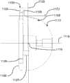
图11是图1的板的实施方案的另一个透视图。FIG. 11 is another perspective view of the embodiment of the panel of FIG. 1 .
图12是图1的板的实施方案的端视图。FIG. 12 is an end view of an embodiment of the panel of FIG. 1 .
图13是将关节盂球固定至肩部骨骼的一部分以增强关节盂球固定的方法的实施方案的框图。13 is a block diagram of an embodiment of a method of securing the glenosphere to a portion of a shoulder bone to enhance glenosphere fixation.
图14是具有罩部分的关节盂球的实施方案的透视图。14 is a perspective view of an embodiment of a glenosphere with a cap portion.
图15是图14的关节盂球的实施方案的截面图。15 is a cross-sectional view of an embodiment of the glenosphere of FIG. 14 .
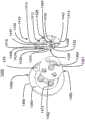
图16是关节盂球、板和用于将关节盂球紧固至板的紧固构件的实施方案的分解透视图。16 is an exploded perspective view of an embodiment of the glenosphere, plate, and fastening members for securing the glenosphere to the plate.
图17是图16的板的实施方案的透视图。FIG. 17 is a perspective view of an embodiment of the plate of FIG. 16 .
图18是图16的关节盂球的实施方案的截面图。18 is a cross-sectional view of an embodiment of the glenosphere of FIG. 16 .
图19是具有用于接合板的接合段的关节盂球的实施方案的透视图。19 is a perspective view of an embodiment of a glenosphere with an articulation segment for engaging a plate.
图20是板和关节盂球的组件的实施方案的透视图,其中关节盂球的用于接收骨固定构件的通道平行于关节盂球的接合轴定向。20 is a perspective view of an embodiment of a plate and glenosphere assembly in which the channel of the glenosphere for receiving a bone fixation member is oriented parallel to the axis of coaptation of the glenosphere.
图21是图20的组件的实施方案的分解透视图。FIG. 21 is an exploded perspective view of an embodiment of the assembly of FIG. 20 .
图22是图20的关节盂球的实施方案的截面图。22 is a cross-sectional view of an embodiment of the glenosphere of FIG. 20 .
图23A是包括凸缘的关节盂球的实施方案的透视图。23A is a perspective view of an embodiment of a glenosphere including a flange.
图23B是图23A的关节盂球的实施方案的前视图。23B is a front view of the embodiment of the glenosphere of FIG. 23A.
图23C是图23A的关节盂球的实施方案的横截面视图。23C is a cross-sectional view of an embodiment of the glenosphere of FIG. 23A.
图24是包括凸缘的关节盂球的实施方案的后透视图。24 is a rear perspective view of an embodiment of the glenosphere including a flange.
图25A是关节盂球的实施方案的透视图,其中凸缘从关节盂球的中心偏移。25A is a perspective view of an embodiment of the glenosphere with the flange offset from the center of the glenosphere.
图25B是图25A的关节盂球的实施方案的横截面视图。25B is a cross-sectional view of an embodiment of the glenosphere of FIG. 25A.
图26A是包括成角度的凸缘的关节盂球的实施方案的透视图。26A is a perspective view of an embodiment of a glenosphere including an angled flange.
图26B是图26A的关节盂球的实施方案的横截面视图。26B is a cross-sectional view of an embodiment of the glenosphere of FIG. 26A.
图27A是包括弯曲的凸缘的关节盂球的实施方案的侧视图。27A is a side view of an embodiment of a glenosphere including a curved flange.
图27B是图27A的关节盂球的实施方案的横截面视图。27B is a cross-sectional view of an embodiment of the glenosphere of FIG. 27A.
图28A是包括插入部件的关节盂球系统的实施方案的分解的前透视图。28A is an exploded front perspective view of an embodiment of a glenosphere system including an insertion component.
图28B是图28A的关节盂球系统的实施方案的分解的顶侧透视图。28B is an exploded top perspective view of the embodiment of the glenosphere system of FIG. 28A.
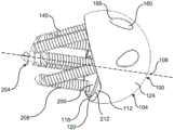
图28C是图28A的关节盂球系统在固定至肩部骨骼时的实施方案的侧视图。28C is a side view of the embodiment of the glenosphere system of FIG. 28A when secured to a shoulder bone.
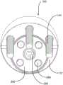
图28D是图28A的关节盂球系统的实施方案的俯透视图。28D is a top perspective view of an embodiment of the glenosphere system of FIG. 28A.
图28E是图28A的关节盂球系统的实施方案的横截面视图。28E is a cross-sectional view of an embodiment of the glenosphere system of FIG. 28A.
图28F是图28A的关节盂球系统的实施方案的分解的左后侧透视图。28F is an exploded left posterior perspective view of the embodiment of the glenosphere system of FIG. 28A.
图28G是图28A的关节盂球系统的实施方案的分解的左前侧透视图。28G is an exploded left anterior perspective view of the embodiment of the glenosphere system of FIG. 28A.
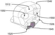
图29A是包括至少一个第二通道的关节盂球系统在固定至肩部骨骼时的实施方案的后透视图。29A is a posterior perspective view of an embodiment of the glenosphere system including at least one second channel when secured to a shoulder bone.
图29B是图29A的关节盂球系统的实施方案的后透视分解图。29B is a posterior perspective exploded view of the embodiment of the glenosphere system of FIG. 29A.
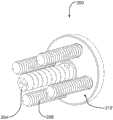
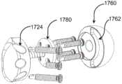
图29C是图29A的关节盂球系统的插入部件的实施方案的后部透视图。29C is a posterior perspective view of an embodiment of an insertion component of the glenosphere system of FIG. 29A.
图29D是图29C的插入部件的实施方案的右前透视图。Figure 29D is a right front perspective view of the embodiment of the insertion component of Figure 29C.
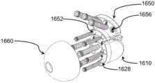
图30A是包括凸缘部件的关节盂球系统的实施方案的左后透视分解图。30A is a left posterior perspective exploded view of an embodiment of a glenosphere system including a flange component.
图30B是图30A的关节盂球系统的实施方案的右后透视分解图。30B is a right posterior perspective exploded view of the embodiment of the glenosphere system of FIG. 30A.
图30C是图30A的关节盂球系统的实施方案的右后顶视透视分解图。30C is a right posterior top perspective exploded view of the embodiment of the glenosphere system of FIG. 30A.
图30D是图30A的关节盂球系统的实施方案的右前透视分解图。30D is a right anterior perspective exploded view of the embodiment of the glenosphere system of FIG. 30A.
图31A是包括成角度的表面插入部件的关节盂球系统的实施方案的右后透视分解图。31A is a right posterior perspective exploded view of an embodiment of a glenosphere system including an angled surface insertion component.
图31B是图31A的关节盂球系统的实施方案的左前透视分解图。31B is a left front perspective exploded view of the embodiment of the glenosphere system of FIG. 31A.
图31C是图31A的关节盂球系统的实施方案的前透视分解图。31C is an exploded front perspective view of the embodiment of the glenosphere system of FIG. 31A.
图32是包括具有平行表面的插入部件的关节盂球系统的实施方案的前透视分解图。32 is an exploded front perspective view of an embodiment of a glenosphere system including an insertion component having parallel surfaces.
图33是包括具有平行表面和通道的插入部件的关节盂球系统的实施方案的前透视图。33 is a front perspective view of an embodiment of a glenosphere system including an insertion component having parallel surfaces and channels.
图34是包括具有成角度的表面和通道的插入部件的关节盂球系统的实施方案的左透视分解图。34 is a left perspective exploded view of an embodiment of a glenosphere system including an insertion component having an angled surface and a channel.
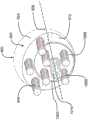
图35A是包括多个插入部件的关节盂球系统的实施方案的前透视图。35A is a front perspective view of an embodiment of a glenosphere system including multiple insertion components.
图35B是包括具有连续表面的插入部件的图35A的关节盂球系统的实施方案的前分解透视图。35B is a front exploded perspective view of the embodiment of the glenosphere system of FIG. 35A including an insertion member having a continuous surface.
详细描述A detailed description
以下详细描述和附图描述并且例示了各种关节盂球系统、方法和部件。提供说明书和附图以使得本领域技术人员能够制造并且使用一种或多种关节盂球系统和/或部件,和/或实践一种或多种方法。它们不旨在以任何方式限制权利要求的范围。The following detailed description and accompanying drawings describe and illustrate various glenosphere systems, methods, and components. The instructions and drawings are provided to enable a person skilled in the art to make and use one or more glenosphere systems and/or components, and/or practice one or more methods. They are not intended to limit the scope of the claims in any way.
除非另有说明,否则“例如(e.g.)”、“等”、“例如(for example)”、“在实施例中”和“或”以及语法上相关的术语的使用表示非排他性的替代方案,而没有限制。“任选地”和语法上相关的术语的使用意指随后描述的元件、事件、特征或情况可以存在/发生或者可以不存在/未发生,并且该描述包括所述元件、事件、特征或情况发生的实例以及所述元件、事件、特征或情况未发生的实例。“连接的”和“联接的”以及语法上相关的术语的使用是指在中间具有或不具有一个或多个其他元件的情况下两个或更多个元件和/或装置的固定的、可释放的或集成的联合。因此,术语“连接的”或“联接的”和语法上相关的术语包括在存在或不存在一个或多个其他元件介于中间的情况下可释放地连接或固定地连接两个或更多个元件和/或装置。如本文所用,使用术语“近端”和“远端”来描述相对于解剖学位置描述的特定元件或特征的相对轴向端部。Unless otherwise stated, the use of "e.g.", "etc", "for example", "in an example" and "or" and grammatically related terms denote non-exclusive alternatives, without limitation. The use of "optionally" and grammatically relative terms means that the subsequently described element, event, feature or circumstance may be present/occurring or may not be present/occurring, and that the description includes said element, event, feature or circumstance instances of occurring and instances of said element, event, feature or circumstance not occurring. The use of "connected" and "coupled", as well as grammatically related terms, refers to the fixed, movable, or fixed connection of two or more elements and/or devices with or without one or more other elements in between. Released or integrated union. Accordingly, the terms "connected" or "coupled" and grammatically related terms include releasably connected or fixedly connected two or more components with or without the intervening presence of one or more other elements. components and/or devices. As used herein, the terms "proximal" and "distal" are used to describe opposite axial ends of a particular element or feature described relative to an anatomical location.
A.增强固定的关节盂球及相关方法A. Enhanced fixation of the glenosphere and related methods
在现有的解决方案中,肩部置换装置可能由于关节盂骨损失或其他恶化而随时间丧失有效性,这可能由于由肩假体施加至一部分肩部骨骼的力而加剧。尽管可以使用骨移植物来补充与一部分肩部骨骼接触的板与一部分肩部骨骼之间的接合,但骨移植物的有用性可能因骨损失而降低。本解决方案提供了用于通过增强关节盂球至一部分肩部骨骼的固定来改善肩假体的系统、方法和设备。关节盂球包括主体、第一表面、第二表面、腔和多个通道。主体限定了穿过主体的中心轴。第一表面包括第一边缘和第二边缘。第一边缘相对于中心轴从第二边缘径向向外定位。第二表面从第一表面的第一边缘延伸。第二表面具有凸形形状。腔从第一表面延伸至主体内。腔包括腔壁和腔表面,所述腔壁在基本上平行于中心轴的方向上从第二边缘延伸至主体中。腔被配置成接收限定干扰空间的板。多个通道从第一表面穿过主体延伸到第二表面。每个通道限定定位在第一边缘与第二边缘之间的第一表面上的第一开口,并且限定定位在第二表面上的第二开口。每个通道被配置成定向以限定穿过通道并且当板被接收在腔中时定位在干扰空间之外的通道轴。多个关节盂球固定构件可以通过多个通道接收,以将关节盂球固定至一部分肩部骨骼。因此,可以增强关节盂球至肩部的固定,以便减轻关节盂骨损失或否则将使肩关节恶化并降低肩假体的有效性的肩关节的其他变化。In existing solutions, shoulder replacement devices may lose effectiveness over time due to glenoid bone loss or other deterioration, which may be exacerbated by the forces applied by the shoulder prosthesis to a portion of the shoulder bone. Although a bone graft can be used to supplement the joint between the plate that contacts a portion of the shoulder bone and a portion of the shoulder bone, the usefulness of the bone graft may be diminished by bone loss. The present solution provides systems, methods and devices for improving shoulder prosthesis by enhancing the fixation of the glenosphere to a portion of the shoulder bone. The glenosphere includes a body, a first surface, a second surface, a cavity, and a plurality of channels. The body defines a central axis passing through the body. The first surface includes a first edge and a second edge. The first edge is located radially outward from the second edge relative to the central axis. The second surface extends from the first edge of the first surface. The second surface has a convex shape. A cavity extends from the first surface into the body. The cavity includes a cavity wall extending from the second edge into the body in a direction substantially parallel to the central axis and a cavity surface. The cavity is configured to receive a plate defining an interference space. A plurality of channels extend through the body from the first surface to the second surface. Each channel defines a first opening positioned on the first surface between the first edge and the second edge, and defines a second opening positioned on the second surface. Each channel is configured to be oriented to define a channel axis passing through the channel and positioned out of the interfering space when the plate is received in the cavity. A plurality of glenosphere fixation members may be received through the plurality of channels to fix the glenosphere to a portion of the shoulder bone. Thus, fixation of the glenosphere to the shoulder can be enhanced in order to mitigate glenoid bone loss or other changes in the shoulder joint that would otherwise aggravate the shoulder joint and reduce the effectiveness of the shoulder prosthesis.
参考图1,示出了包括关节盂球100和固定至肩部骨骼的一部分10的板200的肩假体的透视图。例如,通过关节盂球100的接合构件与板200的接合构件的接合,关节盂球100联接至板200。关节盂球100可以被定向并且进一步固定(例如,固定、连接等)至与板200连接的一部分骨不同的所述一部分骨之外的部分10。在一些实施方案中,将关节盂球固定至肩部骨骼的部分10减小了肩部骨骼的部分10上的应力,以减轻关节盂球骨损失的损伤。Referring to FIG. 1 , a perspective view of a shoulder prosthesis comprising a
在各种实施方案中,关节盂球100被配置成联接至各种板中的任一个。例如,板可以包括各种形状(例如,圆柱形、卵形、矩形、凸形、凹形等)。板可以形成为单个板(例如,与图1中所示的板200类似或相同),或者可以形成为多个板(例如,固定至肩部骨骼的离散部分的多个板)。关节盂球100可以被配置成以各种方式联接至板,所述方式例如通过使用各种紧固构件和/或接合构件(例如,螺钉、螺栓、压配合件、摩擦接合件、接片、锁等)。在一些实施方案中,关节盂球100可以被配置成包括一个或多个接合特征,所述接合特征的尺寸被调整成、配置成或设计成与关节盂球联接的相应板的相应接合特征接合。In various embodiments, the
在一些实施方案中,关节盂球100用作肱骨(未示出)与肩部骨骼之间的球窝关节中的球。通过增强关节盂球至肩部骨骼的固定,本解决方案可以提高用于患者的肩假体的有效性,包括提高患者使用其肱骨的能力。例如,增强关节盂球100至肩部骨骼的固定可以促进将关节盂球100定向在解剖方向,允许患者在解剖或天然运动范围内使用其肱骨。In some embodiments, the
在一些实施方案中,关节盂球100和板200被提供在手术套件中或以其他方式配对在一起,例如在单次手术中被固定至肩部骨骼的一部分10上。在一些实施方案中,板200已经被固定至部分10,并且关节盂球100被设计成与板200互补、增强板200的固定、替换现有的肩假体部件(例如,现有的关节盂球)等。关节盂球100可以被定制成或以其他方式设计成匹配特定的板200。关节盂球100可以与各种板200具有广泛的或通用的相容性。In some embodiments, the
在一些实施方案中,关节盂球100被定制成或以其他方式被设计成与特定的患者相容。例如,可以基于关于患者肩部的信息(例如,成像数据(例如,MRI数据等))和/或基于关于板200的信息来生成关节盂球100的模型。所述信息可以指示用于将关节盂球100固定至部分10的部分10上的目标位置。例如,信息可以包括在部分10的表面上的目标位置,通过所述目标位置,固定构件将被驱动以将关节盂球100固定至部分10。信息可以指示板200的干扰空间。信息可以指示部分10上已经发生或可能发生骨损失的位置,例如用于在将关节盂球100固定至部分10时避开这些位置。例如,基于关于患者肩部和/或板200的信息,可以制造关节盂球100,使得用于将关节盂球100固定至部分10的固定构件定位在板200的干扰空间之外,并且在关于骨损失稳定的位置处进入部分10。在一些实施方案中,这可以通过定向接收有固定构件的关节盂球100的多个通道来实现。当板200接收在关节盂球100中并且固定构件接收在多个通道中时,固定构件穿过在干扰空间之外的通道,并且可以在干扰空间之外的位置处进入部分10。In some embodiments, the
参考图2,示出了当板200接收在关节盂球100中时关节盂球100和板200的详细的透视图。关节盂球100包括主体104。主体限定中心轴108。主体104可以包括各种形状。例如,在各种实施方案中,主体104可以包括球形形状、基本上圆柱形的形状、或允许关节盂球100充当肩假体的零件的任何其他形状。主体104可以由各种材料形成,包括生物相容性材料,例如金属、合金或陶瓷材料。Referring to FIG. 2 , there is shown a detailed perspective view of the
关节盂球100的中心轴108通常定义为横向于接收在关节盂球100中的板200(例如,当关节盂球100定位成使得关节盂球100接触板200时,板200至少部分地定位在关节盂球100的特征内,例如图3至图6中所示的腔128等)的轴。例如,关节盂球100可以包括接收表面或接合构件,例如允许关节盂球100与板200之间的莫尔斯锥度在平行于或基本上平行于中心轴108的方向上从关节盂球100延伸的接合构件。中心轴108可以穿过关节盂球100的中心或接近关节盂球100的中心或中心平面。The
关节盂球100包括第一表面112,所述第一表面112包括第一边缘116和第二边缘120。第一边缘116从第二边缘120径向向外定位,例如通过相对于中心轴108和/或在中心轴108与第一表面112相交处径向向外定位。在一些实施方案中,第一表面112包括被配置成接触肩部骨骼的一部分10的材料。例如,第一表面112可以包括被配置成接合部分10以将关节盂球100联接至部分10的纹理表面。The
关节盂球100包括第二表面124。第二表面124从第一表面112的第一边缘116延伸。例如,如图2中所示,第一边缘116和第二表面124中的每一个都包括弓形形状,使得第二表面124的边缘遵循第一边缘116的弓形形状。The
第二表面124具有凸形形状。第二表面124的凸形形状允许第二表面124接合肩假体系统的其他部分,例如连接至肱骨(未示出)的关节。例如,第二表面124的凸形形状可以为关节盂球100提供球形或基本上球形的形状,以便充当球窝关节假体系统中的球,使得关节可以围绕第二表面124进行关节运动。The
在一些实施方案中,例如图2至图8中所示,关节盂球100可以具有大于或等于半球形形状的形状。例如,关节盂球100占比由从关节盂球100的中心延伸的半径限定的半球体更大的体积(中心可以由关节盂球100的半径相交处的点,在关节盂球100上叠加的完整球体的半径相交处的点等限定)。通过具有大于或等于半球形形状的形状,关节盂球100可以被配置成更远离部分10地与基板200接触,当关节盂球100固定至部分10时,为关节盂球100提供了相对于肩部骨骼更大的游隙,并且可以以其他方式改善患者的关节盂球100的运动学。In some embodiments, such as shown in FIGS. 2-8 , the
在一些实施方案中,例如图3中所示,相对于穿过关节盂球100的中心的轴,中心轴108朝向关节盂球100的外部(例如,朝向第二表面124,远离多个通道160,如图3中所示并且如本文描述的)定位或偏移(例如,中心轴108定位在穿过关节盂球100的中心的轴与正切于第二表面124的轴之间)。通过使中心轴108朝向关节盂球100的外部定位,关节盂球100可以改善患者的运动学。In some embodiments, such as shown in FIG. 3 , the
关节盂球100可以被配置成接收一个或多个关节盂球固定构件140。关节盂球固定构件140被配置成将关节盂球100固定至肩部骨骼的部分10。关节盂球固定构件140被配置成定位在板200的干扰空间之外。关节盂球固定构件140可以包括接合特征(例如,关节盂球固定构件140的外表面上的螺纹)或允许关节盂球固定构件140被驱动穿过部分10以摩擦地固定在肩部骨骼中的其他元件。关节盂球固定构件140可以包括多种部件,包括紧固件、螺钉(例如,压紧螺钉、锥形螺钉)、螺栓等。The
关节盂球100包括多个通道160。多个通道160从第一表面112穿过主体104延伸到第二表面124。每个通道160限定定位在第一表面112上的第一开口(例如,图3中所示的第一开口164)和定位在第二表面124上的第二开口168。多个通道160允许相应的多个关节盂球固定构件140通过多个通道160被接收。通道160可以被配置成接收相应的关节盂球固定构件140,使得关节盂球固定构件140可以可连接至一部分骨,所述一部分骨不同于将连接结构(例如,板200)固定至骨的连接固定构件连接至骨的一部分骨。The
在各种实施方案中,关节盂球100可以包括各种数量的通道160(例如1、2、3、4、5等)。多个通道160中的一个或多个可以被配置成接收关节盂球固定构件140。例如,多个通道160中的一个或多个可以包括被配置成关节盂球固定构件140的相互接合的接合特征的接合接收特征(例如,从通道160延伸的位于通道160的表面上的狭槽、螺纹等)。In various embodiments, the
在一些实施方案中,在通道160中接收比通道160的数量少的关节盂球固定构件140。例如,关节盂球100可以包括被配置成接收关节盂球固定构件140的四个通道160。根据包括板固定构件208将板200连接到骨的位置、由板200(或其他部件,例如骨接合构件204、板固定构件208等)限定的干扰空间的形状、和/或部分10的表面状况(例如,对关节盂骨损失的易感性)在内的因素,三个关节盂球固定构件140可以接收在四个通道160中的三个中,使得关节盂球固定构件140穿过干扰空间之外以进入一部分肩部骨骼的部分10。也可以使用关节盂球固定构件140和通道160的其他此类组合。In some embodiments, fewer
在一些实施方案中,基于部分10的成像数据和部分10的骨丢失模型中的至少一种来确定肩部骨骼的部分10上的目标位置,在该位置将关节盂球固定构件140固定至部分10。可以配置或设计(例如,在定制设计过程中设计以匹配特定部分10和/或板200)并且制造关节盂球100,使得通过通道160接收的关节盂球固定构件140可以在目标位置处固定至部分10。可以定向(例如,定位和/或旋转)关节盂球100,使得通过通道160接收的关节盂球固定构件140可以在目标位置处固定至部分10。基于板200和板固定构件208的几何形状,关节盂球100可以被配置成使得通道160具有不与在板200中的接收板固定构件208相交的通道轴172。In some embodiments, a target location on
在一些实施方案中,通道160是锥形的(例如,通道160的横截面面积从第一开口164变化成第二开口168)。例如,通道160可以是锥形的,以减小从第二开口168到第一开口164的横截面面积,这可以通过使用第一开口164作为焦点来促进定向关节盂球100,并且这可以改善通道160与关节盂球固定构件140之间的摩擦配合。In some embodiments, the
板200可以包括骨接合构件204。骨接合构件204从板200延伸。在一些实施方案中,当板200接收在关节盂球100中时,骨接合构件204沿着关节盂球100的中心轴延伸。在一些实施方案中,当板接收在关节盂球100中时,骨接合构件204相对于关节盂球100的中心轴偏移和/或偏斜。在一些实施方案中,骨接合构件204与板200一体地形成。在其他实施方案中,骨接合构件204可以与板200分开并且接收在板200的开口中。
骨接合构件204可以被配置成将板200固定至肩部骨骼的部分10。骨接合构件204可以包括接合特征(例如,位于骨接合构件204的外表面上的螺纹)或允许骨接合构件204被驱动穿过部分10的表面以摩擦地固定在肩部骨骼中的其他元件。
板200可以被配置成接收板固定构件208。板固定构件208可以与关节盂球固定构件140类似或相同。板固定构件208可以在平行于骨接合构件204的方向上从板200延伸。板固定构件208可以在相对于骨接合构件204偏移和/或偏斜的方向上延伸。在一些实施方案中,当板200接收在关节盂球100的腔128中时,板固定构件208以相对于中心轴108的偏移角定向。在各种实施方案中,板200可以被配置成接收各种数量的板固定构件208(例如1、2、3、4、5等)。
在一些实施方案中,板固定构件208和关节盂球固定构件140可以包括具有相反方向的接合特征(例如,位于板固定构件208的外表面上的螺纹和具有相反螺纹形状的关节盂球固定构件140),使得施加于板200和关节盂球100的力可以根据力的方向经由板200或关节盂球100分配。In some embodiments, the
在一些实施方案中,板200可以限定干扰空间。干扰空间表示其中用于将关节盂球100固定至部分10的固定构件(例如,关节盂球固定构件140)不穿过的空间中的区域。因此,可以定向关节盂球100,使得关节盂球100不干扰板200至部分10的固定。相反,通过关节盂球固定构件140增强关节盂球100至部分10的固定,这加强了板200和关节盂球100与部分10之间的连接,有助于减轻骨损失损伤。在一些实施方案中,干扰空间延伸至部分10的表面。在一些实施方案中,例如如果板形成为多个板,则干扰空间可以包括多个区域,例如与多个板中的一个或多个相对应的多个离散和/或重叠的区域。In some embodiments, the
在一些实施方案中,板200的板固定构件208可以限定干扰空间。例如,干扰空间可以包括由板固定构件208占据的体积,例如由板固定构件208精确占据的体积、基本上由板固定构件208占据的体积、由边界区域(例如,由从板固定构件208向外延伸的空间体积构成的边界区域,例如相对于板固定构件208的尺寸的分数距离(fractional distance))补充的板固定构件208精确占据的体积等。干扰空间还可以至少部分地由板200的骨接合构件204限定。在一些实施方案中,干扰空间可以是由板固定构件占据的联接板200的骨内的体积或区域。In some embodiments, the
在一些实施方案中,干扰空间被限定为包括板固定构件208之间的内部体积的至少一部分,以便可以定向关节盂球100使得任何关节盂球固定构件140均定位在多个板固定构件208的外部。在其他实施方案中,干扰空间被限定为排除板固定构件208之间的内部体积的至少一部分,以便可以定向关节盂球100使得至少一个关节盂球固定构件140可以至少部分地定位在至少两个板固定构件208之间。In some embodiments, an interference space is defined to include at least a portion of the interior volume between the
现参考图3至图6,示出了与板200和任何固定构件分开的关节盂球100。关节盂球100包括腔128。腔128从第一表面112延伸到主体内。腔由腔壁132和腔表面136限定,所述腔壁132在基本上平行于中心轴108的方向上从第一表面112的第二边缘120延伸到腔表面136。Referring now to FIGS. 3-6 , the
腔128被配置成接收板200,使得腔表面136接触板200的表面(例如,图10中所示的第二板表面216等)。例如,腔128可以包括与板200的第二板表面216的形状的至少一部分匹配的形状。腔128可以包括与板表面216的圆周相对应的圆周。如图3和图6中所示,腔128包括被配置成与板200的形状相匹配的基本上圆形的形状,使得腔壁132可以接合板200的外边缘。
如图3中所示,定位腔128使得由主体104限定的中心轴108穿过横向(例如,垂直)于腔表面136的腔128。因此,板200可以被接收在腔128中,使得板200的骨接合构件沿着中心轴108定位。As shown in FIG. 3 ,
在一些实施方案中,腔128的腔表面136包括摩擦元件,该摩擦元件被配置成摩擦接合板200的第二板表面216。例如,腔表面136可以包括纹理表面,其增强腔128与板200之间的摩擦接合。表面之间的摩擦接合可以有助于将施加到关节盂球100上的力分配到板200上,以便分配传递到肩部骨骼的部分10上的力。在一些实施方案中,腔128包括被配置成接合板200的相应锁定元件(例如,钩、闩锁、凸缘等)的锁定元件(例如,钩、闩锁、凸缘等)。例如,定向关节盂球100使得腔128接收板200可以包括将锁定元件对准并且将关节盂球100与板200按压到一起,或者将关节盂球100相对于板200旋转以将关节盂球100锁定至板200上。In some embodiments,
在一些实施方案中,第一表面112包括基本上垂直于中心轴108的第一区域176和与第一区域176成一定角度设置的第二区域180。例如,第二区域180可以与第一区域176形成钝角。腔表面136与第一表面112之间的腔壁132的长度可以在第一区域176与第二区域180之间连续地增加,使得腔表面136保持与第一区域176和第二区域180相邻的平坦或平面形状。腔壁132的第一部分从与第一区域176相邻的第二边缘120的一部分延伸,腔壁132的第二部分从与第二区域180相邻的第二边缘120的第二部分延伸。In some embodiments, the
在一些实施方案中,多个通道160的一个或多个第一开口164定位在第二区域180上。如图3中所示,多个通道160的每个第一开口164定位在第二区域180上。将第一开口164定位在第二区域180上可以促进定向关节盂球100,使得关节盂球固定构件(例如,图2中所示的关节盂球固定构件140等)可以定位成穿过由板200限定的干扰空间之外的多个通道160。在一些实施方案中,第一开口164中的至少一个定位在第一区域176上,以便将至少一个关节盂球固定构件140以与其他关节盂球固定构件140成一定角度定向。In some embodiments, the one or more
多个通道160限定穿过多个通道160的多个通道轴172。如图3中所示,通道轴172垂直于第一表面112定位。多个通道从第一表面112上的第一开口164延伸至第二表面124上的第二开口168。如图3至图6中所示,通道轴172可以彼此平行地定向。在各种实施方案中,可以改变多个通道160的方向并且从而改变通道轴的方向,以便改变穿过多个通道轴172的关节盂球固定构件140延伸的方向。例如,虽然图3示出了垂直于第一表面112定向的通道160(例如,通道轴172垂直于第一表面112),但是在其他实施方案中,通道160可以与第一表面112成锐角定向。例如,将通道160与第一表面112成锐角定向,使得通道160的通道轴172与中心轴108之间的距离随着轴108、轴172远离关节盂球100延伸(例如,朝向肩部骨骼的部分10延伸,在基本上垂直于第一表面112或第二表面116的方向上延伸等)而减小,允许关节盂球固定构件140在相对靠近板200固定至部分10的位置处固定至部分10,这可以减小肩假体所需的部分10的表面积。在另一个实例中,将通道160与第一表面112成锐角定向,使得通道160的通道轴172和中心轴108之间的距离随着轴108、轴172远离关节盂球100延伸(例如,朝向肩部骨骼的部分10延伸,在基本上垂直于第一表面112或第二表面116的方向上延伸等)而增加,允许关节盂球固定构件140在相对靠近板200固定至部分10的位置处固定至部分10,这可以减小肩假体所需的部分10的表面上的应力。在一些实施方案中,多个通道160中的至少一个垂直于第一表面112定向,并且多个通道160中的至少一个与第一表面112成锐角定向。The plurality of
在其中关节盂球100包括具有第一区域176和与第一区域176成一定角度设置的第二区域180的第一表面112的实施方案中,垂直于第一表面112和第二区域180的通道轴172与中心轴108成一定角度定向。例如,如果第二区域180相对于第一区域176成钝角设置,则通道轴172将相对于中心轴108成锐角定向。以这种方式,通过多个通道160接收并且沿着通道轴172定位的关节盂球固定构件140可以定位在板200的干扰空间之外,但在板的板接合构件接合部分10的位置附近接合部分10的一部分。In embodiments in which the
进一步参考图3和图6,在一些实施方案中,腔128包括内腔部分184。内腔部分184可以包括第二腔壁186和第二腔表面188。内腔部分184可以被配置成接收从板(例如,板200)的表面延伸的部件。例如,内腔部分184可以充当用于接合板200的相应接合构件(例如,如图11中所示的接合构件236等)的接合构件。例如,内腔部分184可以是或包括配置成接合板200的第二接合构件236的第一接合构件。在一些实施方案中,内腔部分184被配置成与板200的接合构件236形成莫尔斯锥度。在一些实施方案中,内腔部分184和接合构件236包括用于将关节盂球100固定至板200的互补接合元件(例如,钩、闩锁、凸缘、螺纹联接等)。With further reference to FIGS. 3 and 6 , in some embodiments, the
现在参考图7至图9,示出了具有固定构件的各种构造的关节盂球100和板200。在图7中,示出了具有固定构件的关节盂球100和板200的端视图。多个关节盂球固定构件140接收在关节盂球100的多个通道160中。多个板固定构件208从板200延伸。在图8中,示出了具有关节盂球固定构件140的关节盂球100的透视图。在图9中,示出了具有板固定构件208的板200的透视图。Referring now to FIGS. 7-9 ,
在图7中,从关节盂球100的中心轴(例如,图8中所示的中心轴108)俯视示出了关节盂球100和板200,并且板200的骨接合构件204沿着中心轴108定向。换言之,骨接合构件204和板200的轴与关节盂球100的中心轴108同轴。如图7中进一步所示,多个板固定构件208在与骨接合构件204相同的方向上定向,使得它们平行于中心轴108和骨接合件204并且从中心轴108和骨接合件204偏移。In FIG. 7 , the
多个关节盂球固定构件140可以相对于中心轴108和骨接合构件204以及板固定构件208成一定角度延伸。例如,如图7和图8中所示,关节盂球100的第一表面112包括第一区域176和相对于第一区域176成钝角定向的第二区域180。多个通道160的多个第一开口164定位在第一表面112的第二区域180中,使得多个关节盂球固定构件140与中心轴108成一定角度从关节盂球100延伸出,因此当板200接收在关节盂球100中时,相对于从板200延伸的部件成一定角度。当板200接收在关节盂球100中时,关节盂球固定构件140被配置成延伸出第一开口164,穿过板200的干扰空间,以将关节盂球100固定至肩部骨骼的部分10。The plurality of
进一步参考图9,板固定构件208在与骨接合构件204相同的方向上从板200延伸。板固定构件208可以具有各种长度。例如,板固定构件208可以具有与骨接合构件204类似的长度,例如具有略小于骨接合构件204的长度的长度。板固定构件208的长度可以基于指示用于接收接合构件的肩部骨骼的部分10的相容性的成像数据来选择。With further reference to FIG. 9 ,
现在参考图10至图12,示出了与关节盂球100和任何固定构件分开的板200。板200包括在骨接合构件204从其中延伸的板200的一侧上的第一板表面212,以及在板200的与第一板表面212相对的一侧上的第二板表面216。板主体220被设置在第一板表面212与第二板表面216之间。板主体220包括沿着板主体220的外部(例如,圆周)的板壁224。在一些实施方案中,板主体220和板壁224被配置成接收在关节盂球的腔中,使得板壁224与腔的壁(例如,如图3中所示的关节盂球100的腔128、腔壁132等)平齐地定位。板200的第二板表面216可与腔128的表面(例如,如图3中所示的腔表面136等)平齐地定位。Referring now to FIGS. 10-12 , the
板200包括多个板通道228。每个板通道228从第一表面212上的开口延伸至第二板表面216上的开口。多个板通道228被配置成接收多个板固定构件(例如,图9中所示的板固定构件208等)。多个板通道228可以包括接合接收表面(例如,螺纹表面),所述接合接收表面被配置成接收并且接合板固定构件208的接合特征(例如,螺纹),以便当板200固定至肩部骨骼的部分10时将板200摩擦地联接至板固定构件208。多个板通道228可以横向(例如,垂直)于板轴232定向,以及骨接合构件204被定向,使得当板固定构件通过多个板通道228被接收时,板固定构件208可以平行于骨接合构件204定向。在各种实施方案中,多个板通道228可以相对于板轴232成各种角度定向,并且可以相对于彼此成不均一的角度定向。例如,多个板通道228中的每一个可以与板轴232偏移一定角度定向。当板200接收在关节盂球100的腔128中时,多个板通道228中的每一个可以与中心轴108偏移一定角度定向。
如图10至图12中所示,骨接合构件204与板200一体地形成。在一些实施方案中,板200可以包括被配置成接收骨接合构件204的接收表面。As shown in FIGS. 10-12 ,
在一些实施方案中,如图11和图12中所示,板200包括接合构件236,所述接合构件236被配置成将板200接合至关节盂球100,使得板200可以被固定并且接收在关节盂球100的腔中(例如,如图6中所示,通过接合关节盂球100的腔128的内腔部分184等)。例如,通过接合接合构件236和腔128(例如,通过在腔128的内腔部分184与接合构件236之间形成莫尔斯锥度),可以将关节盂球100和板200彼此固定。接合构件236可以在与骨接合构件204相反的方向上从板200的第二板表面216延伸。例如,接合构件236可以沿着板轴232定向,使得当板200接收在关节盂球100中时,骨接合构件204和接合构件236与关节盂球100的中心轴(例如,图3中所示的中心轴108等)同轴。In some embodiments, as shown in FIGS. 11 and 12 , the
在一些实施方案中,多个通道160包括标记,所述标记被配置成当接收板200时促进定向关节盂球100,使得穿过关节盂球100的关节盂球固定构件140将定位在干扰空间之外。例如,标记可以平行于穿过通道160的通道轴172定位,使得在标记之后的视线可以指示与板200的干扰空间的相交。标记可以包括荧光材料或被配置成在视觉上帮助关节盂球100的定向的其他材料。In some embodiments, plurality of
在一些实施方案中,可以使用具有与多个关节盂球固定构件140类似的形状因子的通道引导件以促进定向关节盂球100。例如,引导件可以以与关节盂球固定构件140类似的方式穿过多个通道160插入,以便确定关节盂球固定构件140是否与板200的干扰空间相交或穿过板200的干扰空间之外。通道引导件可以可拆卸地插入多个通道160中,以便在使用关节盂球固定构件140固定关节盂球100之前快速定向关节盂球100。In some embodiments, a channel guide having a similar form factor as plurality of
现在参考图13,示出了将关节盂球固定至肩部骨骼的一部分以及固定至固定于肩部骨骼的一部分的板的方法400的框图,例如作为肩关节成形术的一部分进行的方法。方法400可以使用本文公开的任何装置和系统实现,包括关于图1至图12描述的关节盂球100和板200。各种行为者可以进行方法400,包括但不限于医疗护理专业人员(例如,医生、护士)等。Referring now to FIG. 13 , shown is a block diagram of a
在410处,将关节盂球与板相邻定位。将板固定至肩部骨骼的一部分。关节盂球包括限定穿过主体的中心轴的主体。关节盂球包括第一表面和第二表面,所述第一表面包括第一边缘和第二边缘,所述第二表面从所述第一边缘延伸。第二表面具有凸形形状。关节盂球包括从第一表面延伸至主体内的腔。腔被配置成接收板。关节盂球包括从第一表面穿过主体延伸至第二表面的多个通道。每个通道限定定位在第一边缘与第二边缘之间的第一表面上的第一开口,限定定位在第二表面上的第二开口,并且限定穿过通道的通道轴。定位关节盂球可以包括保持关节盂球与板相邻(例如在板的距离内),使得板的部件通过关节盂球的通道是可见的。例如,外科医生或其他医学专业人员可以将关节盂球与板相邻定位,使得外科医生可以相对于板操纵关节盂球。At 410, the glenosphere is positioned adjacent the plate. Secures the plate to a portion of the shoulder bone. The glenosphere includes a body defining a central axis passing through the body. The glenosphere includes a first surface including a first edge and a second edge, and a second surface, the second surface extending from the first edge. The second surface has a convex shape. The glenosphere includes a cavity extending from the first surface into the body. The cavity is configured to receive the plate. The glenosphere includes a plurality of channels extending through the body from a first surface to a second surface. Each channel defines a first opening positioned on the first surface between the first edge and the second edge, defines a second opening positioned on the second surface, and defines a channel axis through the channel. Positioning the glenosphere may include maintaining the glenosphere adjacent to the plate (eg, within a distance of the plate) such that passage of components of the plate through the glenosphere is visible. For example, a surgeon or other medical professional may position the glenosphere adjacent to the plate such that the surgeon can manipulate the glenosphere relative to the plate.
在420处,关节盂球相对于板定向。例如,可以定向关节盂球,使得关节盂球的中心轴与板的板轴同轴。在一些实施方案中,板已经被固定至肩部骨骼的一部分,因此关节盂球可以相对于固定的板和板的固定的板轴定向。可以定向关节盂球,使得关节盂球将处于解剖位置,允许当肩关节成形术完成时天然的运动范围。在一些实施方案中,关节盂球可以离轴定向或以其他方式偏移解剖位置定向,允许不同的运动范围。例如,外科医生或其他医学专业人员可以将关节盂球相对于板定向。At 420, the glenosphere is oriented relative to the plate. For example, the glenosphere can be oriented such that the central axis of the glenosphere is coaxial with the plate axis of the plate. In some embodiments, the plate has been fixed to a portion of the shoulder bone so that the glenosphere can be oriented relative to the fixed plate and the fixed plate axis of the plate. The glenosphere can be oriented such that the glenosphere will be in an anatomical position, allowing a natural range of motion when the shoulder arthroplasty is completed. In some embodiments, the glenosphere can be oriented off-axis or otherwise offset from the anatomical position, allowing for different ranges of motion. For example, a surgeon or other medical professional can orient the glenosphere relative to the plate.
在430处,关节盂球的通道轴定位在板的干扰空间之外。干扰空间可以由板固定构件和/或板的骨接合构件限定。干扰空间可以包括板固定构件和/或骨接合构件的精确体积,或者可以包括小于或大于这些部件的体积。将通道轴定位在干扰空间之外促进定位关节盂球固定构件,使得关节盂球固定构件不与板固定构件或骨接合构件碰撞。干扰空间可以视觉上确定、通过使用标记引导件确定、或通过其组合确定。例如,外科医生或其他医学专业人员可以确定干扰空间的范围,以及定位关节盂球,并且由此定位相对于关节盂球固定的通道轴,使得通道轴定位在干扰空间之外。At 430, the channel axis of the glenosphere is positioned outside the interference space of the plate. The interference space may be defined by the plate fixation member and/or the bone engaging member of the plate. The interference space may comprise the precise volume of the plate fixation member and/or the bone engaging member, or may comprise a volume smaller or larger than these components. Locating the channel axis out of the interference space facilitates positioning the glenosphere fixation component such that the glenosphere fixation component does not collide with the plate fixation component or the bone engaging component. Interference spaces may be determined visually, by using marking guides, or by a combination thereof. For example, a surgeon or other medical professional may determine the extent of the interference space and position the glenosphere, and thereby position the channel axis fixed relative to the glenosphere such that the channel axis is positioned outside the interference space.
在一些实施方案中,定位通道轴包括将标记引导件定位在多个通道中以对准多个通道。例如,标记引导件可以指示通道轴的方向。在一些实施方案中,定位通道轴包括在多个通道中可拆卸地接收通道引导件。通道引导件可以包括与关节盂球固定构件类似或相同的形状因子。例如,通道引导件可以在与接收关节盂球固定构件类似的方向上被接收在多个通道中,并且可以调节关节盂球的方向直到通道引导件(以及因此通道轴)定位在干扰空间之外。例如,定向关节盂球可以包括在多个通道中接收多个通道引导件,以及修改关节盂球的方向直到每个通道引导件定位在干扰空间之外。外科医生或其他医学专业人员可以通过多个通道插入通道引导件,并且基于每个通道引导件是否定位在干扰空间之外来修改关节盂球的方向。In some embodiments, positioning the channel axis includes positioning a marker guide in the plurality of channels to align the plurality of channels. For example, a marking guide may indicate the direction of the channel axis. In some embodiments, positioning the channel shaft includes removably receiving channel guides in the plurality of channels. The channel guide may comprise a similar or the same form factor as the glenosphere fixation member. For example, the channel guide can be received in multiple channels in a similar orientation as the glenosphere fixation member is received, and the orientation of the glenosphere can be adjusted until the channel guide (and thus the channel axis) is positioned outside the interfering space . For example, orienting the glenosphere may include receiving a plurality of channel guides in the plurality of channels, and modifying the orientation of the glenosphere until each channel guide is positioned outside of the interference space. A surgeon or other medical professional may insert channel guides through multiple channels and modify the orientation of the glenosphere based on whether each channel guide is positioned outside of the interference space.
在一些实施方案中,定位通道轴包括定向关节盂球,使得通道轴定位在干扰空间之外(例如,通道轴不与干扰空间相交)。在一些实施方案中,定位通道轴包括定向关节盂球,使得围绕每个相应通道轴的体积定位在干扰空间之外(例如,围绕每个相应通道轴的体积不与干扰空间相交)。围绕每个相应通道轴的体积可以是相应通道的外延,例如从通道的开口延伸的圆柱形体积。In some embodiments, positioning the channel axis includes orienting the glenosphere such that the channel axis is positioned outside of the interference space (eg, the channel axis does not intersect the interference space). In some embodiments, positioning the channel axes includes orienting the glenosphere such that the volume around each respective channel axis is positioned outside of the interference space (eg, the volume around each respective channel axis does not intersect the interference space). The volume around each respective channel axis may be an extension of the respective channel, eg a cylindrical volume extending from the opening of the channel.
在一些实施方案中,定位通道轴包括基于在板被接收在关节盂球中之前的关节盂球的第一位置与在板被接收在关节盂球中之后的关节盂球的第二位置之间的偏移来定位通道轴。例如,在第一位置中,关节盂球可以被定位和定向,使得通道轴与干扰空间相交,但当板被接收在关节盂球中时(例如通过将关节盂球沿着板的板轴朝向肩部骨骼的一部分和板移动,从而减小关节盂球与板之间的距离),通道轴变成定位在干扰空间之外。在一些实施方案中,使用具有形状和相对于关节盂球固定构件的长度偏移(例如基于关节盂球的腔的尺寸的偏移)的引导件长度的通道引导件,使得当板被接收在关节盂球的腔内时,通道引导件与通道轴的位置匹配。In some embodiments, positioning the channel axis comprises a distance between a first position of the glenosphere before the plate is received in the glenosphere and a second position of the glenosphere after the plate is received in the glenosphere offset to position the channel axis. For example, in a first position, the glenosphere can be positioned and oriented such that the channel axis intersects the interfering space, but when the plate is received in the glenosphere (for example by orienting the glenosphere along the plate axis of the plate towards part of the shoulder bone and the plate move, thereby reducing the distance between the glenosphere and the plate), the channel axis becomes positioned outside the interfering space. In some embodiments, a channel guide having a shape and guide length offset relative to the length of the glenosphere fixation member (eg, an offset based on the size of the lumen of the glenosphere) is used such that when the plate is received in the The channel guide matches the position of the channel axis when in the lumen of the glenosphere.
在一些实施方案中,定向关节盂球包括定向通道,使得接收在通道中的关节盂球固定构件连接至一部分骨,其不同于将板固定构件连接至骨的一部分骨。在一些实施方案中,干扰空间由板固定构件占据的骨区域限定,以减少板与骨的连接的失败。In some embodiments, the orienting glenosphere includes an orienting channel such that the glenosphere fixation member received in the channel is attached to a portion of bone that is different from the portion of bone attaching the plate fixation member to the bone. In some embodiments, the interference space is defined by the area of bone occupied by the plate fixation member to reduce failure of the plate-to-bone connection.
在440处,将板接收在关节盂球的腔中。例如,可以将关节盂球抵靠板按压,使得板装配进腔中。通道轴将继续定位在板的干扰空间之外。在一些实施方案中,接收板包括将关节盂球的第一接合构件与板的第二接合构件接合,例如用于在关节盂球与板之间形成莫尔斯锥度。在一些实施方案中,当板被接收在腔中时,腔的腔壁被配置成与板的板壁平齐地定位,并且腔的腔表面被配置成与板的表面平齐地定位。例如,已经定位和定向关节盂球使得关节盂球的中心轴与板的板轴同轴并且通道轴定位在干扰空间之外的外科医生可以将关节盂球朝着板和肩部骨骼的一部分移动,使得板装配进腔中。At 440, the plate is received in the lumen of the glenosphere. For example, the glenosphere can be pressed against the plate so that the plate fits into the cavity. The channel axis will continue to be positioned outside the interfering space of the plate. In some embodiments, receiving the plate includes engaging the first engagement member of the glenosphere with the second engagement member of the plate, eg, to form a Morse taper between the glenosphere and the plate. In some embodiments, the cavity wall of the cavity is configured to lie flush with the plate wall of the plate and the cavity surface of the cavity is configured to lie flush with the surface of the plate when the plate is received in the cavity. For example, a surgeon who has positioned and oriented the glenosphere such that the central axis of the glenosphere is coaxial with the plate axis of the plate and the channel axis is positioned outside the interfering space can move the glenosphere towards the plate and part of the shoulder bone , so that the board fits into the cavity.
在450处,多个关节盂球固定构件被接收在多个通道中。因为已经定向关节盂球使得通道轴(或围绕通道轴的体积)定位在板的干扰空间之外,所以关节盂球固定构件在被接收在多个通道中时也将定位在干扰空间之外。外科医生可以将关节盂球固定构件放入通道中,使得关节盂球固定构件定位在干扰空间之外,并且使得关节盂球固定构件接触它们将被固定的肩部骨骼的部分。At 450, a plurality of glenosphere fixation members are received in a plurality of channels. Because the glenosphere has been oriented such that the channel axis (or the volume surrounding the channel axis) is positioned outside the interfering space of the plate, the glenosphere fixation member will also be positioned outside the interfering space when received in the channels. The surgeon may place the glenosphere fixation members into the channel such that the glenosphere fixation members are positioned out of the interfering space and such that the glenosphere fixation members contact the portion of the shoulder bone to which they are to be fixed.
在460处,将多个关节盂球固定构件固定至肩部骨骼的部分,以便增强关节盂球至肩部骨骼的部分的固定。关节盂球固定构件可以包括被配置成接合肩部骨骼的部分的接合特征(例如,螺纹或其他摩擦元件)。因此,将关节盂球固定构件固定至肩部骨骼的部分允许通过关节盂球和板传递到肩部骨骼的部分的力被传递到除了骨接合构件和/或板固定构件被固定至肩部骨骼的部分的位置之外的位置,从而有助于在肩部骨骼的部分上分配应力并且减轻骨损失。例如,外科医生可以使用驱动器、钻或其他工具将关节盂球固定构件驱动进肩部骨骼的部分中,以将关节盂球固定至肩部骨骼的部分。At 460, a plurality of glenosphere fixation members are secured to the portion of the shoulder bone to enhance fixation of the glenosphere to the portion of the shoulder bone. The glenosphere fixation member may include engagement features (eg, threads or other friction elements) configured to engage portions of the shoulder bone. Therefore, fixing the glenosphere fixation member to the part of the shoulder bone allows the force transmitted by the glenosphere and the plate to the part of the shoulder bone to be transmitted to the bone engaging member and/or the plate fixation member is fixed to the shoulder bone position outside of the portion of the shoulder bone, thereby helping to distribute stress on portions of the shoulder bone and mitigate bone loss. For example, a surgeon may use a driver, drill, or other tool to drive the glenosphere fixation member into the portion of the shoulder bone to secure the glenosphere to the portion of the shoulder bone.
在一些实施方案中,方法包括基于关于患者的成像数据定位板和关节盂球中的一个或多个。成像数据可以识别板和/或关节盂球的优选位置,以便在解剖位置提供肩假体系统,以减轻骨丢失或使骨损失的影响最小化等。成像数据可以指示用于将固定构件固定至肩部骨骼的部分的目标位置。In some embodiments, the method includes positioning one or more of the plate and the glenosphere based on imaging data about the patient. The imaging data can identify a preferred location of the plate and/or glenosphere to provide the shoulder prosthesis system in an anatomical position to mitigate bone loss or minimize the effects of bone loss, among other things. The imaging data may indicate the target location of the portion for securing the fixation member to the shoulder bone.
在一些实施方案中,将关节盂球固定至肩部骨骼的部分以及固定至与肩部骨骼的部分固定的板上的方法包括将关节盂球与板相邻定位。关节盂球可以包括:主体,其限定穿过主体的中心轴;第一表面,其包括第一边缘和第二边缘;第二表面,其从第一表面的第一边缘延伸,第二表面具有凸形形状;腔,其从第一表面延伸到主体中,腔被配置成接收板;以及多个通道,其从第一表面穿过主体延伸至第二表面。每个通道可以限定定位在第一边缘与第二边缘之间的第一表面上的第一开口。每个通道可以限定定位在第二表面上的第二开口。每个通道可以被配置成接收骨固定构件,骨固定构件被配置成将关节盂球固定至骨。方法可以包括将关节盂球相对于板定向,使得由通道接收的每个关节盂球固定构件可连接至一部分骨,所述一部分骨不同于板固定结构将板连接至骨处的一部分骨。方法可以包括将关节盂球相对于板定向,使得由通道接收的每个关节盂球固定构件可连接至干扰空间之外的一部分骨,所述干扰空间由将板连接至骨的板固定构件占据的骨的区域限定。方法可以包括将板接收到腔中。方法可以包括经由多个第二开口将多个关节盂球固定构件接收在多个通道中,使得多个关节盂球固定构件定位在干扰空间之外并且接触一部分肩部骨骼。方法可以包括将多个关节盂球固定构件固定至一部分肩部骨骼。在一些实施方案中,定向关节盂球包括在多个通道中接收多个通道引导件,并且修改关节盂球的方向直到每个通道引导件定位在干扰空间之外。In some embodiments, the method of securing the glenosphere to the portion of the shoulder bone and to the plate secured to the portion of the shoulder bone includes positioning the glenosphere adjacent to the plate. The glenosphere may include: a body defining a central axis passing through the body; a first surface including a first edge and a second edge; a second surface extending from the first edge of the first surface, the second surface having A convex shape; a cavity extending from the first surface into the body, the cavity configured to receive the plate; and a plurality of channels extending from the first surface through the body to the second surface. Each channel may define a first opening positioned on the first surface between the first edge and the second edge. Each channel may define a second opening positioned on the second surface. Each channel can be configured to receive a bone fixation member configured to fix the glenosphere to the bone. The method may include orienting the glenosphere relative to the plate such that each glenosphere fixation member received by the channel is connectable to a portion of bone different from the portion of bone where the plate fixation structure connects the plate to the bone. The method may include orienting the glenosphere relative to the plate such that each glenosphere fixation member received by the channel is connectable to a portion of the bone outside of the interfering space occupied by the plate fixation member connecting the plate to the bone The area of the bone is defined. The method may include receiving the plate into the cavity. The method may include receiving the plurality of glenosphere fixation members in the plurality of channels via the second plurality of openings such that the plurality of glenosphere fixation members are positioned out of the interference space and in contact with a portion of the shoulder bone. The method may include securing a plurality of glenosphere fixation members to a portion of the shoulder bone. In some embodiments, orienting the glenosphere includes receiving a plurality of channel guides in the plurality of channels, and modifying the orientation of the glenosphere until each channel guide is positioned outside of the interference space.
B.用于增强固定的关节盂球的其他实施方案和相关方法B. Other Embodiments and Related Methods for Enhanced Fixation of the Glenoid
现在参考图14至图22,例示了用于增强固定的关节盂球的各种实施方案。参考图14至图22描述的关节盂球可以与参考图1至图13描述的关节盂球100类似,并且可以被配置成与各种基板接合或以其他方式相互作用,所述基板包括参考图1至图13描述的板200。尽管本文参考图14至图22描述了关节盂球的罩特征和偏移接合轴,但图1至图13的关节盂球100也可以包括罩或其他延伸结构(例如,位于或围绕关节盂球100的第二区域180的罩)。在一些实施方案中,具有罩的关节盂球对于具有肩假体的患者是运动学上有利的,因为罩提供肩假体和肩部骨骼之间的额外接触点,以防止当患者移动通过关节盂球连接到肩部的臂时摇摆(例如,关节盂球的非预期运动,例如在患者身体的冠状平面内的旋转)。在一些实施方案中,具有与关节盂球的中心偏移或隔开的接合轴的关节盂球可以通过增加可以被关节盂球(或关节盂球和基板)接合的肩部骨骼的有效表面积而不显著增加关节盂球的形状因子来改善关节盂球的运动学。在一些实施方案中,例如在关节盂球包括一个或多个用于接收将关节盂球连接至肩部骨骼的关节盂球固定构件的通道的情况下,偏移接合轴和罩可以配合以在选择通道的方向以及因此固定肩假体的肩部骨骼的部分上提供更大的自由度。Referring now to FIGS. 14-22 , various embodiments of the glenosphere for enhanced fixation are illustrated. The glenosphere described with reference to FIGS. 14-22 may be similar to the
现在参考图14至图15,示出了关节盂球500。关节盂球500可以在结构和功能上与本文描述的各种关节盂球(例如,关节盂球100)类似。关节盂球500包括限定中心506的主体504和穿过主体504的接合轴508。关节盂球500包括第一表面512,第一表面512包括第一边缘516和第二边缘520,第一边缘516从第二边缘520径向向外定位。Referring now to FIGS. 14-15 , a
关节盂球500还包括从第一表面512的第一边缘516延伸的第二表面524。第二表面524可以具有凸形形状。第二表面524可以具有球形形状(例如,第二表面上的所有或基本上所有点与中心点(例如,关节盂球500的中心)等距)。第二表面524和第一表面512可以沿着第一表面512与第二表面524之间的边缘彼此延伸,所述边缘限定了围绕主体504的闭合路径。与关节盂球100的第二表面124不同,第二表面524具有连续的形状(例如,第二表面524不被开口中断),因为关节盂球500不包括用于接收用于将关节盂球500连接至肩部骨骼的固定构件的多个通道;相反,通过联接至板(例如,板200),关节盂球500连接至肩部骨骼。The
中心506可以基于第二表面524来限定。例如,中心506可以是与第二表面524的每个点等距的点,或者是与第二表面524上的大多数点等距的点。在一些实施方案中,当肱骨部件(未示出)被配置成围绕第二表面524进行关节运动时,中心506将因此成为肱骨部件运动的中心。
与关节盂球100的中心轴108类似,接合轴可以是横向于接收在关节盂球500中的板(例如,板200)的轴(例如,如以下所述横向于腔表面532)。在板包括在板上居中定向的骨接合构件(例如,骨接合构件204)的实施方案中,骨接合构件将与接合轴508对齐。Like
在一些实施方案中,第一表面512包括底表面部分576和罩表面部分580。罩表面部分580从底表面部分576延伸。例如,如图14中所示,罩表面部分580与底表面部分576是连续的。平面510可以由底表面部分576限定或包括底表面部分576。例如,如图14至图15中所示,底表面部分576基本上是平面的(例如在底表面部分576上选择的任意组的三个点可以限定相同的平面510)。如图15中所示,罩表面部分580可以相对于平面510成锐角α定向,和/或相对于底表面部分576成钝角β定向。关节盂球500包括在罩表面部分580与平面510之间的罩部分582。如图15中所示,罩表面部分580基本上是平面的(例如,在罩表面部分580上选择的任意组的三个点可以限定相同的平面,该平面相对于平面510成角度α定向)。在一些实施方案中,罩部分582与接合轴508处于中心506的相对侧。在一些实施方案中,罩部分582成角度(例如,相对于主体504的另一部分成角度,例如通过使罩表面部分580相对于平面510成锐角α定向和/或相对于底表面部分576成钝角β定向)。In some embodiments, the
关节盂球500包括腔528。腔528被配置成接收可连接至骨的连接结构(例如,诸如板200的板)。腔528被限定在主体504内。腔包括由第二边缘520限定的周界。腔可以包括第一腔部分(例如,包括腔壁532和腔表面536的第一腔部分)和第二腔部分(例如,内腔部分584)。第一腔部分可以被配置成与可连接至肩部骨骼的连接结构(例如,板200)接合。在一些实施方案中,不是限定在主体504内或从第一表面512凹入的腔,而是关节盂球包括第一表面512的板接收部分,所述板接收部分被配置成接收并且连接至板200(例如,板接收部分可以是或包括被配置成联接至板200的接合构件的接合特征)。
内腔部分可以限定内腔表面586。在一些实施方案中,内腔表面586从腔表面536处的第一端至限定在第二表面524上的第二表面边缘588处的第二端逐渐变细(例如,半径减小)。在一些实施方案中,内部主体表面590限定在主体504中并且在第二表面边缘588与内腔表面586之间延伸。在一些实施方案中,内腔部分584被配置成或成形为并且大小调整为接合连接结构的接合构件(例如,接合板200的第二接合构件236)。如图14中所示,内腔部分584可以沿着接合轴508定向(例如,垂直于内腔表面586的平面也垂直于接合轴508)。在一些实施方案中,腔528(例如,腔壁532和/或内腔表面586)具有圆柱形或锥形圆柱形(例如,截头锥体状)形状。The lumen portion may define a
在一些实施方案中,底表面部分576和/或罩表面部分580可以具有非平面形状(例如,弯曲的、凹形的等)。在此类实施方案中,罩部分582可以被限定为在罩表面部分580与平面510之间,或者在罩表面部分580和平面(该平面(1)穿过(或包括)第一表面512与第二表面524相交的点(或弧段),并且(2)平行于腔表面536、垂直于腔壁532、和/或平行于腔表面536与腔壁532的至少一部分相交处)之间的主体504的一部分。因此,当板被接收在关节盂球500中并且关节盂球500和板连接至肩部骨骼时,罩部分582可以相对于底表面部分576朝着肩部骨骼延伸,其中罩部分582离底表面部分576最远的一端与肩部骨骼最接近。In some embodiments,
在一些实施方案中,底表面部分576和罩表面部分580可以形成单个基本上平面的或平面的表面(而不是罩表面部分580与底表面部分576成一定角度)。如果腔528从底表面部分576凹入,则罩部分582可以被限定为主体504的一部分,所述部分位于(1)横向于腔的平面(例如,沿着腔壁532与腔壁532和第二表面524最接近地方的最远点处正切于腔壁532的平面)与(2)包括腔表面536上的至少一些点的平面之间。In some embodiments,
接合轴508可以是垂直于接收板所抵靠的表面(例如,腔表面532)的轴,或者是垂直于该表面(例如,腔表面532)上的大多数点的轴。接合轴508可以穿过由内腔表面586限定的通道,和/或可以被限定为与内腔表面586上的所有(或大多数)点等距。
在一些实施方案中,例如图15中所示,中心506与接合轴508间隔偏移量507。偏移量507增加了罩表面部分580与接合轴508之间的距离,并且因此可以增加罩表面部分580与被关节盂球500接收的板(例如,接收在腔528中)之间的距离。在一些实施方案中,由偏移量507引起的间距允许罩表面部分580接合部分肩部骨骼,所述部分肩部骨骼否则将不可接近。In some embodiments, such as shown in FIG. 15 ,
在一些实施方案中,罩表面部分580包括粗糙表面,或配置成接合肩部骨骼的其他表面。例如,罩表面部分580可以具有摩擦系数大于底表面部分的摩擦系数的表面。粗糙表面可以促进罩表面部分580与肩部骨骼的第一部分之间的摩擦接合,以防止当关节盂球500连接至肩部骨骼的第二部分时(例如,当关节盂球500联接至板200,板200被固定至肩部骨骼的第二部分时)关节盂球500的摇摆。In some embodiments, the
现在参考图16至图18,例示了关节盂球600。除了如以下进一步描述的关节盂球600的腔之外,关节盂球600可以在结构和功能上与本文描述的各种关节盂球(例如,关节盂球500)类似。关节盂球600可以被配置成连接至板700。板700可以在结构和功能上与板200类似。板700包括板主体704,所述板主体704具有与骨固定构件716位于同一侧的第一板表面708,以及与第一板表面708相对的第二板表面712。板700还包括接合特征720。如图17中所示,接合特征720包括凹部(例如,开口、通道)。Referring now to FIGS. 16-18 , a
如图16至图18中所示,关节盂球600包括接合段684。接合段684显示为具有锥形圆柱形形状(例如,截头锥体状);在各种实施方案中,接合段684可以具有各种形状,例如非锥形圆柱形形状(例如,接合段684的直径是恒定的)、多边形实心体(例如,长方体)等。接合段684沿着接合轴608延伸。在一些实施方案中,接合段684从接合段684与腔表面636相交(或从腔表面636延伸)处的第一接合端至接合段684终止处的第二接合端逐渐变细。接合段684可以被配置成接合(例如,形成莫氏锥度、连接至、接收或被接收在、联接至)板700的接合特征720。As shown in FIGS. 16-18 , the
在一些实施方案中,接合段684包括外接合表面686。外接合表面686可以从与腔表面632相邻的第一端至外接合表面686终止处的第二端逐渐变细。在一些实施方案中,接合段684(和/或外接合表面686)从腔表面632向外延伸到与腔表面632平行并且与腔表面632最远的关节盂球主体604上的点正切的平面。In some embodiments, the
关节盂球600可以包括凸形或球形的第二表面624。第二表面624可以限定第二表面边缘688。第二表面边缘688位于第二表面624与限定在主体604内的内部主体表面690的相交处。在一些实施方案中,内部主体表面690平行于和/或沿着接合轴608定向。例如,当关节盂球600将板700接收在腔628中,使得骨固定构件716和接合特征720各自沿着接合轴608定向时,内部主体表面690也将沿着接合轴608定向,例如用于接收穿过内部主体表面690的紧固构件,以穿过内部主体表面690接合(例如,连接至)接合特征720。The
内部主体表面690可以被配置成接收紧固构件750。紧固构件750可以被配置成将关节盂球600固定至板700,例如通过对接合段684与接合特征720之间的固定提供额外的固定。内部主体表面690可以具有大于紧固构件750的最大半径的半径(例如,从接合轴608限定的半径)。
接合段684可以限定内腔表面692。内腔表面692可以穿过接合段684的内部延伸。在一些实施方案中,内腔表面692包括从内腔表面的终止端延伸的第一部分694和与第一部分694相邻的第二部分696。
在一些实施方案中,第二部分696连接至内部主体表面690。在一些实施方案中,第一部分694具有等于或大于(例如,大于不到10%、大于不到5%、大于不到2%)紧固构件750的螺纹特征752的半径的半径,并且第二部分696具有等于或大于(例如,大于不到10%、大于不到5%、大于不到2%)紧固构件750的最大半径的半径,使得紧固构件750可以通过第二表面边缘688插入内部主体表面690中并且接收在内腔表面692中,其中螺纹特征752与第一部分694对齐。In some embodiments, the
在一些实施方案中,其中可以接收紧固构件750并且用于将关节盂球600连接至板700的连续接合开口(例如,开口由与开口的至少一个其他表面相邻的一个或多个表面限定)可以由内部主体表面690和内腔表面692限定。In some embodiments, a continuous engagement opening in which
现在参考图19,例示了关节盂球800。除了关节盂球800的接合段之外,关节盂球800可以与本文描述的各种关节盂球(例如,关节盂球800)类似。关节盂球800包括主体804,第二表面824和至少部分由腔表面832和腔壁836限定的腔828。接合段884沿着接合轴808从腔表面832延伸。接合段884可以从接合段884与腔表面832相邻处的第一端至与第一端相对的第二端逐渐变细。与关节盂球600的接合段684不同,接合段884不包括其中可以接收紧固构件的内表面。换言之,接合段884由从腔表面832延伸到横向接合表面886的外接合表面888限定。横向接合表面886限定为连续面(例如,横向接合表面886是实心体,未限定开口等)。此外,与关节盂球600不同,第二表面924是连续的(例如,不包括开口或边缘,例如第二表面边缘688)。Referring now to FIG. 19 , a
现在参考图20至图22,例示了关节盂球900。除了用于接收骨固定构件的通道的方向之外,关节盂球900可以与本文描述的各种关节盂球类似。示出了用于与板1000接合的关节盂球900。板1000可以与本文描述的各种板(例如,板200、板700)类似。板1000包括板主体1004、第一板表面1008和骨接合构件1016,所述骨接合构件1016从板主体1004的与第一板表面1008相同的一侧延伸。Referring now to FIGS. 20-22 , a
在一些实施方案中,第一板表面1008包括接合特征(例如,如图20至图21中所示的相对粗糙的特征),其促进例如用于增强板1000与肩部骨骼之间的固定的骨生长。板1000可以通过板通道1052接收板固定构件1050。In some embodiments, the
关节盂球900包括具有第一表面912和第二表面924的主体904。关节盂球900限定接合轴908。关节盂球900包括一个或多个通道960,所述通道960可以接收用于将关节盂球900连接至肩部骨骼的骨固定构件940。如图22中所示,通道960可以由第一表面912上的第一通道开口964、第二表面924上的第二通道开口968以及将第一通道开口964连接至第二通道开口968的通道表面972限定。The
与关节盂球100的通道160不同,通道960被定向为平行于接合轴908,使得当关节盂球900连接至板1000和肩部骨骼时,通过通道960接收的骨固定构件940将平行于接合轴908、和/或骨接合构件1016和/或板固定构件1050定向。例如,通道960可以限定平行于接合轴908的通道轴976。通道轴976可以被限定为这样的轴,对于该轴,由垂直于该轴的平面与通道表面972之间相交处限定的大多数点与该轴等距(例如,通道轴976对于通道表面972的垂直于通道轴976的大多数或所有的横截面居中定向)。Unlike the
在一些实施方案中,将通道960定向成平行于接合轴908允许关节盂球900固定肩部骨骼的更大的表面积或不同的表面积(尽管与关节盂球100相比,关节盂球900可能对肩部骨骼的特定表面积具有更不牢固的连接)。In some embodiments, orienting the
在一些实施方案中,关节盂球包括球形主体。球形主体可以包括限定围绕主体的完整路径的第一边缘。第一表面可以从第一边缘的第一侧延伸,并且第二表面可以从第一边缘的与第一侧相对的第二侧延伸。例如,第一表面可以沿着第一边缘与第二表面相邻,并且第一表面和第二表面一起可以限定球形主体的完整外表面。球形主体可以限定中心,使得第一表面上的每个点与中心等距(或者使得第一表面上的最大可能数量的点与中心等距)。第一边缘可以限定(或包括)第一点和第二点。第一点与第二点之间沿着第一表面的第一最短路径(例如,使得第一最短路径上与第一边缘相一致的点仅是第一点和第二点)大于由与中心等距的所有点限定的球形区域的圆周的一半。在一些实施方案中,此类关节盂球因此可以包括罩部分(例如,第二点位于罩部分上),或者具有大于半球形的形状因子。In some embodiments, the glenosphere comprises a spherical body. The spherical body may include a first edge defining a complete path around the body. The first surface may extend from a first side of the first edge, and the second surface may extend from a second side of the first edge opposite the first side. For example, the first surface may be adjacent to the second surface along the first edge, and together the first surface and the second surface may define the complete outer surface of the spherical body. The spherical body may define a center such that every point on the first surface is equidistant from the center (or such that the largest possible number of points on the first surface are equidistant from the center). The first edge may define (or include) the first point and the second point. The first shortest path between the first point and the second point along the first surface (for example, so that the points on the first shortest path that coincide with the first edge are only the first point and the second point) is greater than the distance between the first point and the center All points equally spaced define half the circumference of the spherical region. In some embodiments, such a glenosphere may thus include a cap portion (eg, on which the second point is located), or have a larger than hemispherical form factor.
C.具有用于增强固定的凸缘的关节盂球和相关方法C. Glenoid with flange for enhanced fixation and related methods
现在参考图23A至图27B,例示了包括用于增强固定的凸缘型部件的关节盂球的各种实施方案。参考图23至图27B描述的关节盂球可以与参考图1至图22描述的关节盂球类似,并且可以被配置成与各种基板接合或以其他方式相互作用。在一些实施方案中,具有凸缘部件的关节盂球对于具有肩假体的患者是运动学上有利的,因为凸缘使得关节盂球能够接触并且支撑在围绕固定关节盂球和/或基板的固定元件的固定位点的肩部骨骼的更大表面积上,有助于稳定关节盂球以防止摇摆或其他不利的运动。在一些实施方案中,具有用于接收相对于关节盂球的中心偏移的基板的表面的关节盂球可以有利地使凸缘更接近肩部骨骼和/或远离基板被固定至肩部骨骼的固定位点,进一步改善稳定性。在一些实施方案中,凸缘可以促进肩假体与基板之间的力的分配,否则会损坏基板。凸缘可以被配置成定位在关节盂腔的上部或与其接触。与其中关节盂球的部分可以延伸超过半球形形状或布置,但不能改善骨损失应用中的操作的现有系统不同,根据本公开内容的各种实施方案的具有凸缘的关节盂球可以有利地改善在具有骨损失的应用(例如骨损失模型应用)中肩假体的操作。Referring now to FIGS. 23A-27B , various embodiments of a glenosphere including a flange-type component for enhanced fixation are illustrated. The glenosphere described with reference to FIGS. 23-27B may be similar to the glenosphere described with reference to FIGS. 1-22 and may be configured to engage or otherwise interact with various substrates. In some embodiments, a glenosphere with a flange component is kinematically advantageous for patients with shoulder prostheses because the flange enables the glenosphere to contact and rest on the surrounding fixation glenosphere and/or base plate. The greater surface area of the shoulder bone at the fixation site of the fixation element helps to stabilize the glenosphere against sway or other adverse motion. In some embodiments, a glenosphere having a surface for receiving a base plate offset from the center of the glenosphere can advantageously have the flange closer to the shoulder bone and/or away from where the base plate is fixed to the shoulder bone. Fixed position for further improved stability. In some embodiments, the flange can facilitate the distribution of forces between the shoulder prosthesis and the base plate that would otherwise damage the base plate. The flange may be configured to be positioned on or contact the superior portion of the glenoid cavity. Unlike existing systems in which portions of the glenosphere can extend beyond a hemispherical shape or arrangement, but fail to improve handling in bone loss applications, a glenosphere with a flange according to various embodiments of the present disclosure can advantageously The operation of shoulder prostheses in applications with bone loss, such as bone loss phantom applications, can be greatly improved.
现在参考图23A至图23C,示出了关节盂球1100。关节盂球1100可以在结构和功能上与本文描述的各种关节盂球类似。关节盂球1100包括主体1104和凸缘1150。主体1104包括第一主体表面1108和第二主体表面1112。第二主体表面1112可以是球形的(例如,限定了表面,其中许多、大多数或所有点与参考点(例如,主体1104的中心)等距)。主体1104包括配置成与可连接至肩部骨骼的连接结构(例如,板或基板)接合的接合特征1120。Referring now to FIGS. 23A-23C , a
在一些实施方案中,主体1104具有或限定中心1116。中心1116可以是与主体1104外部上的许多、大多数或所有点等距的点,和/或与第二主体表面1112的许多、大多数或所有点等距的点。在一些实施方案中,中心1116可以是联接至主体1104并且被配置成围绕第二主体表面1112进行关节活动的肱骨部件(未示出)的旋转中心。In some embodiments, the
接合特征1120可以是与如本文所述的腔的各种实施方案类似的腔。如图23A至图23C中所示,接合特征1120包括被配置成接收连接结构(例如,板)的第一腔部分1124,以及配置成接合连接结构的第二腔部分1132。第一腔部分1124可以包括腔表面1126(例如,接合表面),连接结构可以抵靠腔表面1126定位或接收。在一些实施方式中,腔表面1126可以通过限定腔深度的壁与第一主体表面1108分开。
主体1104可以限定接合轴1118。接合轴1118可以是穿过接合特征1120并且指示通常将第一球体1100带向肩部骨骼的方向的轴。在一些实施方案中,接合轴1118垂直于或基本上垂直于腔表面1126。当板接收在第一腔部分1124中时,接合轴1118可以与板的板固定构件对齐。在一些实施方案中,例如图23C中所示,接合轴1118穿过中心1116(例如,包括中心1116、与中心1116共线)。The
在一些实施方案中,接合特征1120和/或腔表面1126与主体1104的中心1116(或与包括中心1116并且平行于腔表面1126或腔表面1126的外边缘的平面1128)偏移接合偏移量1127。该偏移量可以增加通过第二主体表面1112能够关节运动的运动范围,因为第二主体表面1112可以占据比被限定为与中心1116等距的半球形空间更大的空间;并且当板被接合特征1120接收并且固定以及关节盂球1100被固定至肩部骨骼时,该偏移量可以使凸缘1150与肩部骨骼更接近。在一些实施方案中,接合偏移量1127为约6mm(例如,大于或等于4mm且小于或等于8mm;大于或等于5mm且小于或等于9mm)。在一些实施方案中,接合偏移量1127为约10mm(例如,大于或等于8mm且小于或等于12mm;大于或等于9mm且小于或等于11mm)。In some embodiments, the
凸缘1150从主体1104径向向外延伸,并且包括与第一主体表面1108邻接的第一凸缘表面1154和与第二主体表面1112邻接的第二凸缘表面1156。凸缘1150可以比第二主体表面1112从主体1104径向向外延伸更远(例如,凸缘1150的至少一部分离中心1116的距离大于第二主体表面1112上的任何点)。在一些实施方案中,凸缘1150具有从第一端1158和第二端1162延伸的凸缘长度(例如,沿着凸缘1150的外边缘1151限定的长度),使得由从中心1116至第一端1158的第一线1159与从中心1116至第二端1162的第二线1163限定的角度γ小于180度(例如,小于150度、小于120度、小于90度、小于180度和大于45度)。主体1104可以包括关节盂球主体表面1110,所述关节盂球主体表面1110包括第一主体表面1108和第一凸缘表面1154。凸缘1150可以通过增加用于将关节盂球1100稳定靠在肩部骨骼上的表面积来为关节盂球1100提供额外的支撑。可以选择角度γ或凸缘1150的尺寸的其他测量值以减小由关节盂球1100占据的总尺寸或体积或者使其最小化。例如,在一些构造中,随着凸缘1150的尺寸增加,可能变得更难以将关节盂球1100放置在盂肱关节中;如果使用太大的凸缘1150,则它可能干扰肱骨的运动范围以及干扰软组织,例如肩胛下肌、冈上肌和/或冈下肌组织。同时,增加或最大化可以接触肩部骨骼的凸缘1150的表面积可以增加关节盂球1100的稳定性或以其他方式改善关节盂球1100的运动学。
在一些实施方案中,凸缘1150包括孔1164,孔1164从由第一凸缘表面1154限定的第一孔开口1166延伸到由第二凸缘表面1156限定的第二孔开口1168。孔1164可以被配置成接收配置成将关节盂球连接至肩部骨骼的关节盂球固定构件1101(例如,与关节盂球固定构件140类似或相同的固定构件)。如图23A至图23C中所示,关节盂球1100包括三个孔1164。在各种实施方案中,凸缘1150可以包括各种数量的孔1164(例如,1个、2个、3个、4个、5个孔)。在其他实施方案中(例如,如图24中所示,凸缘1150不包括孔,例如具有连续或不间断的表面)。In some embodiments, the
在一些实施方案中,第二主体表面1112限定孔路径1168。孔路径1168可以在第二主体表面1112内凹入。孔路径可以朝着中心1116凹入(例如,从第二主体表面1112凹入主体1104中;孔路径1168的表面比第二主体表面1112的相邻部分与中心1116更接近)。孔路径1168与第二孔开口1168连通(例如,与第二孔开口1168邻接,过渡至第二孔开口1168),并且可以将关节盂球固定构件1101引导至孔1164中。当关节盂球固定构件1101接收在孔路径1168中并且穿过孔1164时,关节盂球固定构件的一部分将相对于第二体表面1112与中心1116更接近地定位。In some embodiments, the
孔1164可以被配置成接收多个关节盂球固定构件1101,或者如图23A至图23C中所示,孔1164可以以不同的位置和/或方向接收关节盂球固定构件1101。例如,孔1164可以被配置成以与孔的第一通道1165相对应的第一角度或与孔的第二通道1166相对应的第二角度接收关节盂球固定构件1101。第一通道1165可以限定第一通道轴1173,并且第二通道1166可以限定第二通道轴1175(例如,通道轴可以被限定为与相应表面上的许多、大多数或所有点等距)。通道1165、1166可以彼此邻接。孔路径1168可以包括与每个通道轴1173、1175对准的部分。
通道1165、1166可以被配置成接收和/或固定关节盂球固定构件。例如,通道1165、1166可以包括螺纹接收表面,其被配置成接合关节盂球固定构件1101的螺纹。第一通道轴1173可以限定与第二通道轴1175的通道偏移量1176,使得关节盂球固定构件1101接收在第一通道1165中时的位置与接收在第二通道1166中时的位置偏移。在一些实施方案中,通道偏移量1176为约3mm(例如,大于或等于1mm且小于或等于10mm、大于或等于1mm且小于或等于5mm、大于或等于2mm且小于或等于4mm、3mm)。在一些实施方案中,第一通道轴1173平行于腔表面1126或接合轴1118,并且第二通道轴1175相对于第一通道轴1173与腔表面1126或接合轴1118成角度(例如成10度角、成大于或等于5度且小于或等于20度角;大于或等于7.5度且小于或等于15度角;大于或等于9度且小于或等于11度角)。第一通道轴1173与第二通道轴1175之间的角度可以为在关节盂腔中具有不同尺寸和/或关节盂骨丢失的患者中定向和植入关节盂球1100提供更多的选择。随着角度增加,关节盂球固定构件可以固定至肩部骨骼的位置可以有更多的。例如,该角度能够使关节盂球固定构件固定至喙突或肩峰突的基部处的骨位置(例如,增加或优化稳定性的骨位置)。
孔1164可以限定与通道轴1173、1175等距且落入(例如,包括在内)包括通道1165、1166的平面内的孔中心1178。在凸缘1150包括多于一个孔1164的实施方案中,可以定向通道中心1178与中心1116限定成角度δ(例如,由从中心1116到通道中心1178或通道轴1173、1175的线限定的角度)。角度δ可以指示由凸缘1150覆盖的空间的弧形范围(或其一部分),或是由凸缘1150覆盖的空间的弧形范围(或其一部分)的量度。角度δ可以是约35度(例如,大于或等于20度且小于或等于50度;大于或等于30度且小于或等于40度;大于或等于34度且小于或等于36度)。
现在参考图25A至图25B,示出了具有偏移凸缘1150的关节盂球1100。在一些实施方案中,凸缘1150被配置成与第一主体表面1108偏移。凸缘1150可以偏移,使得当关节盂球1100固定至肩部骨骼时,凸缘1150比第一主体表面1108更接近肩部骨骼,和/或当板被接合特征1120接收并且接合时,凸缘1150延伸出并且超过板。在凸缘1150偏移的实施方案中,关节盂球1100因此可以适于肩部骨骼的各种几何形状,例如用于将凸缘1150拉到更接近远离板被固定至肩部骨骼处的肩部骨骼的一部分。在一些实施方案中,凸缘1150的偏移可以有利地将通道1165、1166定位成更远离关节盂球1100的中心1116(与包括凸缘1150的关节盂球相比),并且由此定位肱骨部件围绕第二主体表面1112进行关节运动的运动范围。此类定位可以减少可能由产生磨损颗粒的肱骨部件与关节盂球1100之间的摩擦导致的骨质溶解的可能性,所述磨损颗粒可以被关节运动的肱骨部件推动穿过通道1165、1166进入肩关节中。Referring now to FIGS. 25A-25B , a
凸缘1150可以与平面1128偏移第一偏移距离1180(例如,如到第一凸缘表面1154处所测量的),第一偏移距离1180大于第一主体表面1108与该平面偏移的第二偏移距离1182。在一些实施方案中,第一偏移距离1180与第二偏移距离1182之间的差为约3mm(例如,大于或等于2mm且小于或等于4mm)、5mm(例如,大于或等于4mm且小于或等于6mm)、或7mm(例如,大于或等于6mm且小于或等于8mm)。偏移量也可相对于腔表面1126或穿过腔表面1126的外边缘的平面来限定。The
现在参考图26A至图26B,示出了关节盂球1200。除了关节盂球主体表面(例如,第一凸缘表面和/或第一主体表面)的形状和/或方向之外,关节盂球1200可以与关节盂球1100类似。关节盂球1200可以包括主体1204、第一主体表面1208和第二主体表面1212。关节盂球1200可以限定中心1216和接合轴1218。关节盂球1200可以包括从主体1204径向向外延伸的凸缘1250。凸缘1250可以包括第一凸缘表面1254和第二凸缘表面1256。关节盂球1200可以包括关节盂球主体表面1210,关节盂球主体表面1210包括第一主体表面1208和第一凸缘表面1254。关节盂球1200可以限定包括或穿过中心1216的平面1228。Referring now to FIGS. 26A-26B , a
在一些实施方案中,定向第一凸缘表面1254和/或关节盂球主体表面1204与平面1228成一定角度。例如,第一凸缘表面1254的第一端1291(例如,第一凸缘表面1254的远离中心1216、接合轴1218和/或与凸缘1250的外边缘相邻的一端)可以与平面1228偏移凸缘偏移量1290,而第一主体表面1208的第二端1209(例如,第一主体表面1208与第二主体表面1212相遇并且与凸缘1250、接合轴1218和/或中心1216最远的一端或点)与平面1228偏移主体偏移量1292,主体偏移量1292小于凸缘偏移量1290。关节盂球主体表面1210可以是平面的或基本上平面的。第一端1291与第二端1292之间的线1293可以限定为相对于主体偏移量1292的角度ε,或者可以类似地限定为线1293与平面1228的相交处的角度(未示出),使得关节盂球主体表面1204相对于平面1228成角度。关节盂球主体表面1204可以成角度,使得主体偏移量1292为约3mm(例如,大于或等于2mm且小于或等于4mm)、5mm(例如,大于或等于4mm且小于或等于6mm)、或7mm(例如,大于或等于6mm且小于或等于8mm)。还可以测量从中心1216至包括或穿过第一点1219并且平行于平面1228的平面1295的主体偏移量。In some embodiments,
现在参考图27A至图27B,示出了关节盂球1300。除了如本文所述的第一凸缘表面和/或关节盂球主体表面的形状之外,关节盂球1300可以与关节盂球1200类似。关节盂球1300可以包括主体1304、第一主体表面1308和第二主体表面1312。关节盂球1300可以限定中心1316、穿过中心1316的接合轴1318、和包括中心1316的平面1328。凸缘1350可以从主体1304径向向外延伸,并且包括第一凸缘表面1354和第二凸缘表面1356。关节盂球主体表面1310可以包括第一主体表面1308和第一凸缘表面1354。关节盂球可以包括接合特征,所述接合特征包括腔表面1326。Referring now to FIGS. 27A-27B , a
在一些实施方案中,关节盂球1300具有弯曲的或非线性的(或非平面的)关节盂球主体表面1310和/或弯曲的或非线性的(或非平面的)第一凸缘表面1310。从平面1328至第一凸缘端1392(例如,第一主体表面1308与第一凸缘表面1354相邻处的点)限定的第一凸缘偏移量1393可以大于从平面1328至外凸缘端1390(例如,第一凸缘表面1354上的最外面的点)限定的第二凸缘偏移量1391。第一凸缘偏移量1393也可以大于平面1328与第一主体端1309a(例如,第一主体表面1308与第二主体表面1312相遇处并且可离凸缘1354最远的主体1304的最外面的点)之间限定的第一主体偏移量1394a,并且可以大于平面1328与第二主体端1309b(例如,接合特征1324的边缘1327与第一主体表面1308相交并且离凸缘1350最远处的点)之间限定的第二体偏移量13094。也可以相对于腔表面1326或穿过腔表面1326的外边缘的平面限定偏移量。在一些实施方案中,当关节盂球1300被固定至肩部骨骼和/或板时,第一凸缘端1392被定位成最接近肩部骨骼,允许通过关节盂球接收的关节盂球固定构件被紧密地固定至肩部骨骼,同时主体1304的大部分远离肩部骨骼定位。In some embodiments, the
D.具有用于增强固定的插入件的关节盂球和相关方法D. Glenoid with Insert for Enhanced Fixation and Related Methods
现在参考图28A至图35B,例示了实现插入件(例如,插入部件)的关节盂球系统的各种实施方案。在各种实施方案中,插入部件的使用可以改善肩关节成形术的功效,这是通过稳定抵靠肩部骨骼(例如,肩胛骨)的关节盂球,允许改善肱骨的运动范围,即使在已经发生关节盂骨损失或其他骨损失时也保持解剖的或其他期望的旋转中心,和/或使得关节盂球直接固定至肩部骨骼(额外地或替代地,将关节盂球经由基板固定至肩部骨骼)来将关节盂球与肩部骨骼之间负荷分配远离基板,以降低基板故障的风险。插入部件可以是模块化的,以允许外科医生在进行肩关节成形术时具有更大的灵活性,以便在现有的基板上安装新的或替换的关节盂球(例如,在移除现有的关节盂球之后,在已经固定至肩部骨骼的基板上安装新的关节盂球)。Referring now to FIGS. 28A-35B , various embodiments of a glenosphere system implementing an insert (eg, insert component) are illustrated. In various embodiments, the use of an insert component can improve the efficacy of shoulder arthroplasty by stabilizing the glenosphere against the shoulder bone (e.g., scapula), allowing for improved range of motion of the humerus, even after Glenoid bone loss or other bone loss also maintains an anatomical or other desired center of rotation, and/or enables direct fixation of the glenosphere to the shoulder bone (additionally or alternatively, fixation of the glenosphere to the shoulder via a base plate bone) to distribute the load between the glenosphere and the shoulder bone away from the base plate to reduce the risk of base plate failure. Insertion components may be modular to allow greater flexibility for the surgeon performing shoulder arthroplasty in order to install a new or replacement glenosphere over an existing base plate (e.g., after removal of an existing After the original glenosphere, a new glenosphere is installed on the base plate already fixed to the shoulder bone).
在一些实施方案中,例如图28A至图35B中所示,关节盂球系统1400包括插入部件1410、关节盂球1460和基板1480。关节盂球1460可以与本文描述的各种关节盂球类似。基板1480可以与本文描述的各种基板类似。基板1480可以接收板固定构件1482,板固定构件1482可以与本文描述的各种固定构件类似。基板1480可以包括骨接合构件1484或与骨接合构件1484相关联,骨接合构件1484可以与本文描述的各种骨接合构件类似。In some embodiments, such as shown in FIGS. 28A-35B , a
在一些实施方案中,关节盂球1460包括第一表面1464、第二表面1468、板接合区域1472和插入件接合区域1476。板接合区域1472被配置成接合基板1480。例如,板接合区域1472可以包括被配置成接收基板1480的腔。插入件接合区域1476被配置成接合插入部件1410。如图28A中所示,插入件接合区域1476可以包括被配置成接收插入部件1410的腔(例如,凹部)。插入件接合区域1476可以包括被配置成由插入部件1410接收的突出物。插入件接合区域1476可以被配置成使用莫尔斯锥度联接至插入部件1410。In some embodiments, the
在一些实施方案中,插入部件1410(例如,插入部件1410的主体)包括第一表面1412、第二表面1416和第三表面1420。第一表面1412可以从第一端1413延伸至第二端1414。第一表面1412可以被配置成接合骨。例如,第一表面1412可以包括被配置成促进骨生长的骨生长表面(例如,粗糙表面、蚀刻表面)。第二表面1416与第一表面1412隔开。第二表面1416可以与第一表面1412配合以限定至少一个通道1428。所述至少一个通道1428可以被配置成接收接合构件以将插入部件1410固定至骨上。在一些实施方案中,插入部件1410包括第四表面1424。In some embodiments, the insertion member 1410 (eg, the body of the insertion member 1410 ) includes a
第三表面1420可以包括第一端1430和第二端1432。第一端1430和第二端1432可以与第一表面1412相邻,使得第一端1430和第二端1432从第一表面1412的周边延伸。第三表面1420可以包括或限定第一端1430与第二端1432之间的弯曲部分1434。弯曲部分可以成形为接触骨接合构件(例如,骨接合构件1484),以便使得插入部件1410能够抵靠与骨接合构件1484相邻的基板1484的一部分定位,这可以有助于稳定关节盂球系统1400和/或将来自基板1480的负荷分配到插入部件1410中。在一些实施方案中,第一表面1412限定从第一端1413至第二端1414的第一弧长(例如,沿着第一表面1412的边缘),并且第三表面1420限定从第一端1430至第二端1432的第二弧长(例如,沿着第三表面1420的边缘)。第一弧长可以大于第二弧长,以便增加插入部件1410在插入部件被配置成接触(例如,接合)肩部骨骼以稳定关节盂球系统1400的区域中的表面轮廓,同时保持插入部件1410可以与基板1480相邻的低轮廓,这可以促进在手术过程期间用各种几何形状的关节盂球系统1400的部件来组装关节盂球系统1400。The
在一些实施方案中,插入部件1410包括腔1436。腔1436可以包括由第一表面1412限定的第一腔开口1438。腔1436可以包括由第二表面1424(或与第二表面1424相邻的插入部件1410的表面)限定的第二腔开口1439。腔1436可以限定在插入部件1410内(例如,在插入部件1410的主体内)。腔1436可以限定第一腔区域1440和第二腔区域1442,它们可以各自与第三腔区域1444共同延伸。如图28A中所示,第三表面1420的弯曲部分1434可以延伸到插入部件1410中,并且由此限定第三腔区域1444的一部分。In some embodiments,
在一些实施方案中,第一腔区域1440限定第一腔直径1446,第二腔区域1442限定第二腔直径1448,并且直径1446、1448各自大于板固定构件1482的直径,使得第一腔区域1440或第二腔区域1442中的至少一个可以接收板固定构件1482。腔1436可以在第三表面1420与至少一个通道1428之间。In some embodiments, the
在一些实施方案中,至少一个第一通道1428限定第一通道轴1429。腔1436可以限定腔轴1437。第一通道轴1429可以平行于腔轴1437,这可以有助于将插入部件1410与基板1480对准。In some embodiments, at least one
如图28A、图28C和图28F中所示,在一些实施方案中,第四表面1424被配置成接合基板1480的第一表面1481。例如,平行于第四表面的第一平面(例如,第四表面1424限定第二开口1439处)可以与平行于第二表面1416的第二平面隔开(例如,其中第二表面1416限定至少一个第一通道1428的开口处)。例如,第一平面可以比第二平面更接近第一表面1412。在一些此类实施方案中,插入部件1410因此可以被配置成通过将基板1480固定至关节盂球1460同时将关节盂球1460固定至肩部骨骼来稳定基板1480和关节盂球1460。As shown in FIGS. 28A , 28C, and 28F , in some embodiments,
现在参考图29A至图29D,在一些实施方案中,关节盂球系统1500包括插入部件1510、关节盂球1560和基板1580。关节盂球系统1500可以与关节盂球系统1400类似,并且包括关节盂球系统1400的特征。如本文所述,关节盂球系统1500可以包括插入部件1510,所述插入部件1510包括至少一个第二通道1550。Referring now to FIGS. 29A-29D , in some embodiments, a
例如,如图29A至图29D中所示,插入部件1510包括至少一个第一通道1528,并且还包括至少一个第二通道1550。所述至少一个第二通道1550可以位于所述至少一个第一通道1528的与腔1536相对的一侧,使得所述至少一个第二通道1550允许将插入部件1510固定至骨的部分,所述骨的部分距离被基板1580固定的部分比所述至少一个第一通道1528更远。插入部件1510可以包括通道表面1518,通道表面1518在插入部件1510的限定至少一个第一通道1528的部分上方延伸,通道表面1518与第一表面1512配合以限定至少一个第二通道1550。所述至少一个第二通道1550被配置成接收骨固定构件(例如骨固定构件1509),骨固定构件被配置成将插入部件1510固定至骨。所述至少一个第二通道1550可以具有大于所述至少一个第一通道1528的直径的直径,以便容纳具有大于所述至少一个第一通道1528的直径的直径的骨固定构件1509(例如,经由所述至少一个第二通道1550改善插入部件1510的固定)。For example, as shown in FIGS. 29A-29D ,
在一些实施方案中,至少一个第二通道1550限定至少一个第二通道轴1551。至少一个第二通道1550可以被配置成使得第二通道轴1551不平行于至少一个第一通道1528的第一通道轴1529。In some embodiments, at least one
在一些实施方案中,插入部件1510的限定至少一个第二通道1550的部分被配置成当插入部件1510接合到关节盂球1560时在关节盂球1560上方延伸。例如,从第一表面1512与第三表面1520相邻处的第一边缘1545至与第一边缘1545相对并且与至少一个第二通道1550相邻的第一表面1512的第二边缘1546的第一距离可以大于从关节盂球1560的插入件接合区域(例如,与关节盂球1460的插入件接合区域1476类似的插入件接合区域)的点至第一表面1564与第二表面1568相邻处的关节盂球边缘的第二距离。In some embodiments, the portion of the
现在参考图30A至图30D,在一些实施方案中,关节盂球系统1600包括插入部件1610或凸缘部件1650中的至少一个。关节盂球系统还包括关节盂球1660和基板1680。关节盂球系统1600可以与本文描述的关节盂球系统1400、1500类似。插入部件1610可以与插入部件1410、1510类似。关节盂球1660可以与关节盂球1460、1560类似。基板1680可以与基板1480、1580类似。在一些实施方案中,凸缘部件1650可以包括与关于图23A至图27B所述的凸缘部件类似的特征并且执行与之类似的功能。Referring now to FIGS. 30A-30D , in some embodiments, the
如图30A至图30D中所示,关节盂球系统1600可以包括插入部件1610和凸缘部件1650中的一个或两个。例如,凸缘部件1650可以使关节盂球1660能够额外地固定至肩部骨骼上(例如,固定至没有被插入部件1610固定的肩部骨骼的部分上)。如图30D中所示,在一些实施方案中,关节盂球1550包括被配置成接合插入部件1610的插入件接合区域1662,并且可以类似地包括被配置成接合凸缘部件1650的凸缘接合区域1664。插入件接合区域1662可以与凸缘接合区域1664径向隔开,以便允许插入部件1610和凸缘部件1650联接至骨的不同部分。在一些实施方案中,凸缘部件1650包括被配置成接收至少一个第一骨固定构件1654的至少一个第一通道1652和被配置成接收至少一个第二骨固定构件1658(其可以具有比至少一个第一骨固定构件1654更大的直径)的至少一个第二通道1656。所述至少一个第二通道1656可以相对于所述至少一个第一通道1652成一定角度定向。关节盂球系统1600可以被配置成使得至少一个第一通道1652平行于插入部件1610的至少一个第一通道1628(例如,基于接合区域1662、1664和通道1628、1652的构造)。As shown in FIGS. 30A-30D , the
现在参考图31A至图31C,在一些实施方案中,关节盂球系统1700包括插入部件1710、关节盂球1760和基板1780。关节盂球系统1700可以与关节盂球系统1400、1500和1600类似。插入部件1710包括成角度的第一表面1720。例如,插入部件1710可以被配置成使得在至少一个通道1721的通道轴1722与(腔1724的)腔轴1724(其中腔轴1724位于与通道轴1722相同的平面中并且与通道轴1722相交)之间限定角度α是直角或近似直角(例如,小于120度、小于105度、小于90度、小于75度、大于45度且小于120度、或它们的各种组合)。Referring now to FIGS. 31A-31C , in some embodiments, a
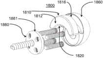
现在参考图32,在一些实施方案中,关节盂球系统1800包括插入部件1810、关节盂球1860和基板1880。除了插入部件1810的构造之外,关节盂球系统1800可以与本文描述的各种关节盂球系统(例如,关节盂球系统1400、1500、1600、1700)类似。如图32中所示,插入部件1810包括第一表面1812、第二表面1816和第三表面1820。第二表面1816与第一表面1812隔开并且平行于第一表面1812。第三表面1820从第一表面1812和第二表面1820延伸,并且可以成形为接收基板1880的边缘表面1881。在一些实施方案中,第一表面1812和第二表面1816形成连续的表面(例如,没有开口,例如关于插入部件1410所述的用于通道或腔的开口)。Referring now to FIG. 32 , in some embodiments, a
现在参考图33,在一些实施方案中,关节盂球系统1900包括插入部件1910、关节盂球1960和基板1980。除了插入部件1910的构造之外,关节盂球系统1900可以与本文描述的各种关节盂球系统(例如,关节盂球系统1400、1500、1600、1700、1800)类似。如图33中所示,插入部件1910可以与插入部件1810类似,并且可以包括被配置成接收至少一个骨固定构件1902的至少一个通道1928。Referring now to FIG. 33 , in some embodiments, a
现在参考图34,在一些实施方案中,关节盂球系统2000包括插入部件2010、关节盂球2060和基板2080。除了插入部件2010的构造之外,关节盂球系统2000可以与本文描述的各种关节盂球系统(例如,关节盂球系统1400、1500、1600、1700、1800、1900)类似。如图34中所示,插入部件2010可以与插入部件1910类似,并且可以包括与第二表面2016隔开并且成一定角度的第一表面2012(例如,平行于第一表面2012的平面可以以锐角与平行于第二表面2016的平面相交),这可以促进将关节盂球系统2000固定至相应的肩部骨骼几何形状。Referring now to FIG. 34 , in some embodiments, a
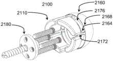
现在参考图35A至图35B,在一些实施方案中,关节盂球系统2100包括多个插入部件2110、关节盂球2160和基板2180。关节盂球系统2100可以与本文描述的各种关节盂球系统(例如,关节盂球系统1400、1500、1600、1700、1800、1900、2000)类似,并且被配置成提供多个插入部件。如图35A至图35B中所示,关节盂球2160包括第一表面2164、第二表面2168和多个插入件接合区域2176,所述插入件接合区域2176可以与板接合区域2172径向向外隔开并且围绕板接合区域2172。多个插入件接合区域2176可以被配置成接合相应的插入部件2110。如图35A中所示,插入部件2110可以包括用于接收骨固定构件(例如,类似于插入部件1910)的通道,而如图35B中所示,插入部件可以包括类似于插入部件1810的连续表面(例如,没有通道)。Referring now to FIGS. 35A-35B , in some embodiments, a
Claims (8)
Translated fromChineseApplications Claiming Priority (3)
| Application Number | Priority Date | Filing Date | Title |
|---|---|---|---|
| US201762526911P | 2017-06-29 | 2017-06-29 | |
| US62/526,911 | 2017-06-29 | ||
| PCT/US2018/040141WO2019006205A1 (en) | 2017-06-29 | 2018-06-28 | Glenosphere with inserts for augmented fixation and related methods |
Publications (2)
| Publication Number | Publication Date |
|---|---|
| CN111405882A CN111405882A (en) | 2020-07-10 |
| CN111405882Btrue CN111405882B (en) | 2023-05-26 |
Family
ID=62976308
Family Applications (1)
| Application Number | Title | Priority Date | Filing Date |
|---|---|---|---|
| CN201880043434.6AActiveCN111405882B (en) | 2017-06-29 | 2018-06-28 | Glenoid with insert for enhanced fixation and related methods |
Country Status (13)
| Country | Link |
|---|---|
| US (2) | US11730604B2 (en) |
| EP (2) | EP3644906B1 (en) |
| JP (3) | JP7258841B2 (en) |
| KR (2) | KR102788656B1 (en) |
| CN (1) | CN111405882B (en) |
| AU (3) | AU2018294239B2 (en) |
| CA (1) | CA3066244A1 (en) |
| DK (1) | DK3644906T3 (en) |
| ES (1) | ES2914088T3 (en) |
| MX (2) | MX2019015297A (en) |
| PL (1) | PL3644906T3 (en) |
| PT (1) | PT3644906T (en) |
| WO (1) | WO2019006205A1 (en) |
Families Citing this family (10)
| Publication number | Priority date | Publication date | Assignee | Title |
|---|---|---|---|---|
| US8778028B2 (en) | 2005-02-25 | 2014-07-15 | Shoulder Innovations, Inc. | Methods and devices for less invasive glenoid replacement |
| US20230080207A1 (en) | 2005-02-25 | 2023-03-16 | Shoulder Innovations, Inc. | Methods and devices for less invasive glenoid replacement |
| CA3032645A1 (en) | 2016-08-01 | 2018-02-08 | Exactech, Inc. | Platform rtsa glenoid prosthesis with modular attachments capable of improving initial fixation, fracture reconstructions, and joint biomechanics |
| KR20250080917A (en) | 2017-01-19 | 2025-06-05 | 앙코르 메디컬, 엘.피.(디/비/에이 디제이오 서지컬) | Shoulder implant components |
| US12138172B2 (en) | 2018-04-30 | 2024-11-12 | Shoulder Innovations, Inc. | Inset/onlay glenoid, porous coated convertible glenoid, and humeral heads with textured undersides |
| EP4406516A3 (en)* | 2019-01-28 | 2024-08-07 | Encore Medical, L.P. (D/B/A Djo Surgical) | Glenoid implant |
| AU2020237088B2 (en) | 2019-03-11 | 2025-09-04 | Shoulder Innovations, Inc. | Total reverse shoulder systems and methods |
| AU2020204539B2 (en)* | 2019-07-12 | 2024-10-31 | Howmedica Osteonics Corp. | Augmented glenoid design |
| EP3982848A1 (en)* | 2019-08-09 | 2022-04-20 | Howmedica Osteonics Corp. | Apparatuses and methods for implanting glenoid prostheses |
| CN114630625A (en) | 2019-10-24 | 2022-06-14 | Ignite骨科有限责任公司 | Orthopedic implant system with reinforcement device and method of use |
Family Cites Families (22)
| Publication number | Priority date | Publication date | Assignee | Title |
|---|---|---|---|---|
| RU2306904C2 (en) | 2003-12-19 | 2007-09-27 | Общество с ограниченной ответственностью "Эндосервис" | Endoprosthesis of shoulder joint |
| US7959680B2 (en)* | 2006-02-02 | 2011-06-14 | Biomet Manufacturing Corp. | Method and apparatus for performing a shoulder implant procedure |
| JP5180953B2 (en) | 2006-03-23 | 2013-04-10 | イグザクテック・インコーポレイテッド | Reverse shoulder glenoid plate and prosthesis |
| ITUD20070122A1 (en)* | 2007-07-03 | 2009-01-04 | Lima Lto S P A | HOMERAL PROSTHESIS |
| US20100217399A1 (en)* | 2009-02-22 | 2010-08-26 | Groh Gordon I | Base plate system for shoulder arthroplasty and method of using the same |
| FR2944694B1 (en) | 2009-04-22 | 2012-05-18 | Tornier Sa | DEVICE FOR FIXING THE GLENE OF A GLENOIDAL ARTICULAR COMPONENT FOR A SHOULDER PROSTHESIS AND CORRESPONDING SHOULDER PROSTHESIS |
| GB2472973B (en)* | 2009-07-28 | 2014-07-09 | Biomet Uk Ltd | A revision acetabular for resurfacing system |
| US8506569B2 (en)* | 2009-12-31 | 2013-08-13 | DePuy Synthes Products, LLC | Reciprocating rasps for use in an orthopaedic surgical procedure |
| AU2012214581A1 (en)* | 2011-02-07 | 2013-08-15 | Exactech, Inc. | Adjustable reverse shoulder prostheses |
| EP2787929B1 (en)* | 2011-12-07 | 2019-05-15 | Smith&Nephew, Inc. | Orthopedic augments having recessed pockets |
| US9421106B2 (en)* | 2011-12-07 | 2016-08-23 | Howmedica Osteonics Corp. | Reverse shoulder baseplate with alignment guide for glenosphere |
| US9439768B2 (en)* | 2011-12-08 | 2016-09-13 | Imds Llc | Glenoid vault fixation |
| EP2630935B1 (en)* | 2012-02-27 | 2014-12-31 | Arthrex, Inc. | Glenoid extension block |
| US9668873B2 (en)* | 2013-03-08 | 2017-06-06 | Biomet Manufacturing, Llc | Modular glenoid base plate with augments |
| EP2967893B1 (en)* | 2013-03-15 | 2017-03-01 | The Cleveland Clinic Foundation | Prosthetic articulation surface mounting |
| US9408699B2 (en)* | 2013-03-15 | 2016-08-09 | Smed-Ta/Td, Llc | Removable augment for medical implant |
| US9345582B2 (en)* | 2013-11-19 | 2016-05-24 | VXP Solutions LLC | Method and apparatus for restoring a shoulder joint and/or another joint |
| US9844440B2 (en)* | 2014-08-14 | 2017-12-19 | Biomet Manufacturing, Llc | Glenoid implant |
| US9597190B2 (en)* | 2015-01-15 | 2017-03-21 | DePuy Synthes Products, Inc. | Modular reverse shoulder orthopaedic implant and method of implanting the same |
| US9861493B2 (en)* | 2015-08-14 | 2018-01-09 | Gerhard E. Maale | Glenoid fossa prosthesis |
| US9782263B1 (en)* | 2016-12-12 | 2017-10-10 | DJP Global, Inc. | Glenosphere with flange for augmented fixation and related methods |
| EP3403617B1 (en)* | 2017-05-19 | 2020-03-18 | Tornier | Augment insert, shoulder prosthesis and kit comprising the augment insert |
- 2018
- 2018-06-28EPEP18743305.7Apatent/EP3644906B1/enactiveActive
- 2018-06-28KRKR1020237041685Apatent/KR102788656B1/enactiveActive
- 2018-06-28JPJP2020500185Apatent/JP7258841B2/enactiveActive
- 2018-06-28PTPT187433057Tpatent/PT3644906T/enunknown
- 2018-06-28USUS16/625,611patent/US11730604B2/enactiveActive
- 2018-06-28KRKR1020207000991Apatent/KR102615907B1/enactiveActive
- 2018-06-28DKDK18743305.7Tpatent/DK3644906T3/enactive
- 2018-06-28EPEP22158013.7Apatent/EP4039231A1/enactivePending
- 2018-06-28MXMX2019015297Apatent/MX2019015297A/enunknown
- 2018-06-28PLPL18743305Tpatent/PL3644906T3/enunknown
- 2018-06-28CNCN201880043434.6Apatent/CN111405882B/enactiveActive
- 2018-06-28CACA3066244Apatent/CA3066244A1/enactivePending
- 2018-06-28AUAU2018294239Apatent/AU2018294239B2/enactiveActive
- 2018-06-28ESES18743305Tpatent/ES2914088T3/enactiveActive
- 2018-06-28WOPCT/US2018/040141patent/WO2019006205A1/ennot_activeCeased
- 2019
- 2019-12-16MXMX2023014820Apatent/MX2023014820A/enunknown
- 2023
- 2023-04-05JPJP2023061095Apatent/JP7642698B2/enactiveActive
- 2023-07-05USUS18/218,277patent/US20230338156A1/enactivePending
- 2023-12-04AUAU2023274243Apatent/AU2023274243B2/enactiveActive
- 2024
- 2024-10-22AUAU2024227524Apatent/AU2024227524A1/enactivePending
- 2025
- 2025-02-26JPJP2025028635Apatent/JP2025071317A/enactivePending
Also Published As
| Publication number | Publication date |
|---|---|
| AU2023274243A1 (en) | 2023-12-21 |
| JP2020526303A (en) | 2020-08-31 |
| RU2019144975A (en) | 2021-07-29 |
| KR102615907B1 (en) | 2023-12-19 |
| ES2914088T3 (en) | 2022-06-07 |
| JP2025071317A (en) | 2025-05-02 |
| JP7258841B2 (en) | 2023-04-17 |
| EP3644906B1 (en) | 2022-02-23 |
| CA3066244A1 (en) | 2019-01-03 |
| AU2018294239B2 (en) | 2023-09-28 |
| DK3644906T3 (en) | 2022-05-23 |
| AU2018294239A1 (en) | 2020-01-16 |
| US11730604B2 (en) | 2023-08-22 |
| WO2019006205A1 (en) | 2019-01-03 |
| RU2019144975A3 (en) | 2021-09-13 |
| MX2023014820A (en) | 2024-01-12 |
| KR102788656B1 (en) | 2025-03-28 |
| PT3644906T (en) | 2022-05-27 |
| AU2024227524A1 (en) | 2024-11-14 |
| US20230338156A1 (en) | 2023-10-26 |
| CN111405882A (en) | 2020-07-10 |
| KR20200094722A (en) | 2020-08-07 |
| JP2023076614A (en) | 2023-06-01 |
| AU2023274243B2 (en) | 2024-11-07 |
| EP3644906A1 (en) | 2020-05-06 |
| PL3644906T3 (en) | 2022-06-13 |
| KR20230169459A (en) | 2023-12-15 |
| MX2019015297A (en) | 2021-03-25 |
| US20200197186A1 (en) | 2020-06-25 |
| JP7642698B2 (en) | 2025-03-10 |
| EP4039231A1 (en) | 2022-08-10 |
Similar Documents
| Publication | Publication Date | Title |
|---|---|---|
| CN111405882B (en) | Glenoid with insert for enhanced fixation and related methods | |
| US12274624B2 (en) | Glenosphere with flange for augmented fixation and related methods | |
| US10856993B2 (en) | Glenosphere with hood for augmented fixation and related methods | |
| TWI539927B (en) | Bone plate for the stabilization of bones, device, and method | |
| US9795490B1 (en) | Glenosphere with augmented fixation and related methods | |
| US9782263B1 (en) | Glenosphere with flange for augmented fixation and related methods | |
| US20250295496A1 (en) | Glenosphere with flange for augmented fixation and related methods | |
| JP2015504763A (en) | Implant fixing member holder |
Legal Events
| Date | Code | Title | Description |
|---|---|---|---|
| PB01 | Publication | ||
| PB01 | Publication | ||
| SE01 | Entry into force of request for substantive examination | ||
| SE01 | Entry into force of request for substantive examination | ||
| GR01 | Patent grant | ||
| GR01 | Patent grant |