CN111405265A - A New Image Rendering Technology - Google Patents
A New Image Rendering TechnologyDownload PDFInfo
- Publication number
- CN111405265A CN111405265ACN202010214373.4ACN202010214373ACN111405265ACN 111405265 ACN111405265 ACN 111405265ACN 202010214373 ACN202010214373 ACN 202010214373ACN 111405265 ACN111405265 ACN 111405265A
- Authority
- CN
- China
- Prior art keywords
- image
- area
- depth
- pixel
- value
- Prior art date
- Legal status (The legal status is an assumption and is not a legal conclusion. Google has not performed a legal analysis and makes no representation as to the accuracy of the status listed.)
- Granted
Links
Images

Classifications
- H—ELECTRICITY
- H04—ELECTRIC COMMUNICATION TECHNIQUE
- H04N—PICTORIAL COMMUNICATION, e.g. TELEVISION
- H04N13/00—Stereoscopic video systems; Multi-view video systems; Details thereof
- H04N13/10—Processing, recording or transmission of stereoscopic or multi-view image signals
- H04N13/106—Processing image signals
- H04N13/122—Improving the 3D impression of stereoscopic images by modifying image signal contents, e.g. by filtering or adding monoscopic depth cues
- H—ELECTRICITY
- H04—ELECTRIC COMMUNICATION TECHNIQUE
- H04N—PICTORIAL COMMUNICATION, e.g. TELEVISION
- H04N13/00—Stereoscopic video systems; Multi-view video systems; Details thereof
- H04N13/20—Image signal generators
- H04N13/275—Image signal generators from 3D object models, e.g. computer-generated stereoscopic image signals
Landscapes
- Engineering & Computer Science (AREA)
- Multimedia (AREA)
- Signal Processing (AREA)
- Processing Or Creating Images (AREA)
- Image Generation (AREA)
Abstract
Description
Translated fromChinese技术领域technical field
本发明涉及图像质量提升领域,尤其涉及一种新型的图像绘制技术。The invention relates to the field of image quality improvement, in particular to a novel image rendering technology.
背景技术Background technique
有资料显示,目前DIBR是绘制不同视角观察图像的主要方法。根据现有的图像将另一视角的图像进行绘制,从而得到在不同视角下所观察到的图像。该绘制方法中最关键的部分是进行3D-WARPING过程,该过程是将一幅图像先恢复至三维模型,然后在另外一处目标视点附近将该三维模型重新投影到目标平面得到虚拟视点处的图像。According to some data, DIBR is currently the main method for drawing images from different viewing angles. An image from another viewing angle is drawn according to an existing image, so as to obtain an image observed under a different viewing angle. The most critical part of the rendering method is to perform the 3D-WARPING process, which is to restore an image to a 3D model, and then reproject the 3D model to the target plane near another target viewpoint to obtain the virtual viewpoint. image.
目前的DIBR绘制技术中只考虑起始视点处的深度值和像素值,并没有将所绘制视点的深度值。而直接按照DIBR方法中的公式进行绘制会导致绘制后的视点位置重新产生移动,导致很多区域发生重复赋值或者没有进行赋值,从而在图像上形成斑块形状的图案,从视觉上仿佛图像中存在空洞。In the current DIBR rendering technology, only the depth value and pixel value at the starting viewpoint are considered, and the depth value of the rendered viewpoint is not considered. Drawing directly according to the formula in the DIBR method will cause the position of the drawn viewpoint to move again, resulting in repeated assignments or no assignments in many areas, thus forming a patch-shaped pattern on the image, which visually seems to exist in the image. Empty.
中国专利文献CN103905813B公开了一种“基于背景提取与分区修复的DIBR空洞填补方法”。首先利用视频序列重建背景图像和背景深度图:利用视频序列和与之对应的深度图序列,比较每个像素点在每帧画面中所对应的深度值,将深度值最大时的像素作为背景图像的像素,通过逐帧比较获得真实的背景图像和与之对应的背景深度图;其次,计算画面中前景图像区域;最后,针对不同区域采取不同策略填补空洞。上述技术方案仅被动地填补空洞,没有在根本上减少空洞数量,耗费大量计算,时间复杂度高。Chinese patent document CN103905813B discloses a "DIBR hole filling method based on background extraction and partition repair". First, use the video sequence to reconstruct the background image and background depth map: use the video sequence and the corresponding depth map sequence to compare the depth value corresponding to each pixel in each frame, and use the pixel with the largest depth value as the background image. The real background image and the corresponding background depth map are obtained through frame-by-frame comparison; secondly, the foreground image area in the picture is calculated; finally, different strategies are adopted for different areas to fill the holes. The above-mentioned technical solutions only passively fill the voids, and do not fundamentally reduce the number of voids, consume a lot of computation, and have high time complexity.
发明内容SUMMARY OF THE INVENTION
本发明主要解决原有的DIBR绘制技术未考虑绘制视点的深度值的技术问题,提供一种新型的图像绘制技术,利用图像之间的深度差值来划分绘制不准确区域,根据图像的实际情况将图像中视觉冲击最明显的区域中的破损区域重新进行绘制,从而让图像的绘制区域变得更加清晰,减少最后一步填充空洞时空洞的个数,从而降低时间复杂度。The invention mainly solves the technical problem that the original DIBR rendering technology does not consider the depth value of the rendering viewpoint, and provides a new type of image rendering technology, which uses the depth difference between the images to divide the inaccurate rendering area, according to the actual situation of the image. The damaged area in the area with the most obvious visual impact in the image is redrawn, so that the drawing area of the image becomes clearer, reducing the number of holes when filling holes in the last step, thereby reducing the time complexity.
本发明的上述技术问题主要是通过下述技术方案得以解决的:本发明包括以下步骤:The above-mentioned technical problems of the present invention are mainly solved by the following technical solutions: the present invention comprises the following steps:
(1)3D图像变换;DIBR技术中最关键的部分为3D图像变换(3D Image Wraping)它是一种针对图像像素进行变化的操作。通过三维变换将参考图像像素点映射到目标视图中,从而形成和参考图像相对应的原始目标视图。该方法本质上通过深度信息构建当前视点的三维信息,进而通过映射变换,得到其他视点的三维信息。(1) 3D image transformation; the most critical part of DIBR technology is 3D image transformation (3D Image Wraping), which is an operation that changes image pixels. The reference image pixels are mapped to the target view through three-dimensional transformation, so as to form the original target view corresponding to the reference image. This method essentially constructs the three-dimensional information of the current viewpoint through depth information, and then obtains the three-dimensional information of other viewpoints through mapping transformation.
(2)利用图像之间的深度差值来划分绘制不准确区域;通过两个视点的深度值进行比较,发现当原图的深度图像和目标视图的深度图像对应位置的深度值存在一定程度的倍率差,定义两个视图深度误差为dif,然后根据深度误差dif确定重新针对深度误差较大的区域进行绘制,确定深度误差的阈值δ。(2) Use the depth difference between the images to divide the inaccurate area; by comparing the depth values of the two viewpoints, it is found that when the depth value of the depth image of the original image and the depth image of the target view correspond to a certain degree If the magnification is poor, the depth error of the two views is defined as dif, and then according to the depth error dif, it is determined to redraw the area with a large depth error, and the threshold δ of the depth error is determined.
(3)设置图像的前景阈值和背景阈值;深度图像中深度值小于αbackgurand区域设为背景区域,大于αforgurand区域设为将两幅深度图像中的背景区域做并逻辑计算,前景区域做并逻辑计算,得到输出视图中的背景区域和前景区域。(3) Set the foreground threshold and background threshold of the image; in the depth image, the area where the depth value is less than αbackgurand is set as the background area, and the area greater than αforgurand is set as the background area in the two depth images. Logical calculation to get the background area and foreground area in the output view.
(4)处理空洞。采用通过空洞周边像素逐步将空洞区域减少的方法进行填充,将这些空洞进行标记,并且将这些孔洞的边缘区域进行标记,填充空洞的顺序是由空洞外侧往空洞内测逐层填充。本质是以像素值之差的最小二范数作为参考依据,选择非空洞区域的像素进行比较,最后找到对应的匹配块并将对应的中心像素填充至修复块中心像素p。然后依次修复每一块空洞边缘像素,直至孔洞填充完毕。(4) Dealing with voids. The method of gradually reducing the hole area through the surrounding pixels of the hole is used to fill, these holes are marked, and the edge areas of these holes are marked. The order of filling the holes is from the outside of the holes to the inside of the holes. The essence is to use the least two-norm of the difference between pixel values as a reference, select pixels in non-hole areas for comparison, and finally find the corresponding matching block and fill the corresponding center pixel to the center pixel p of the repair block. Then repair each hole edge pixel in turn until the hole is filled.
作为优选,所述的假设图像像素p坐标为(u,v),图像平面坐标为(x,y),图像像素坐标列向量为矩阵P,相机矩阵为Camera。Preferably, the assumed image pixel p coordinate is (u, v), the image plane coordinate is (x, y), the image pixel coordinate column vector is matrix P, and the camera matrix is Camera.
M=[x y 1]TM=[xy 1]T
P=[u v 1]TP=[uv 1]T

其中f为相机的焦距,fx和fy分别为像素x方向和像素y方向的焦距。u0,v0,主点的实际位置,单位也是像素。where f is the focal length of the camera, and fx and fy are the focal lengths in the x-direction and y-direction of the pixel, respectively. u0, v0, the actual position of the main point, the unit is also pixel.
将像素坐标和图像平面坐标、相机坐标和实际三维空间的坐标进行互相联系,在像素坐标和图像坐标之间可以通过相机内参矩阵Camera得到运算关系:The pixel coordinates and the image plane coordinates, the camera coordinates and the coordinates of the actual three-dimensional space are related to each other, and the operation relationship between the pixel coordinates and the image coordinates can be obtained through the camera internal parameter matrix Camera:

然后将图像平面坐标转换为以相机为中心的相机坐标(Xc,Yc,Zc),转换关系如下Then convert the image plane coordinates to camera coordinates (Xc , Yc , Zc ) centered on the camera, and the conversion relationship is as follows

在本次实验中定义f为:In this experiment, f is defined as:

接着根据相机坐标系和普通的空间坐标系(Wx,Wy,Wz)进行进一步转换,转换关系为:Then further conversion is performed according to the camera coordinate system and the ordinary space coordinate system (Wx, Wy, Wz). The conversion relationship is:


其中px,py,pz分别表示相机在空间坐标中在x、y、z方向上的平移量。矩阵R表示相机在空间中的旋转矩阵,通常情况下,R表示为单位矩阵。向量[px py pz]T表示相机在空间中的平移量。Among them, px, py, and pz represent the translation amount of the camera in the x, y, and z directions in spatial coordinates, respectively. The matrix R represents the rotation matrix of the camera in space, and in general, R is represented as the identity matrix. The vector [px py pz ]T represents the amount of camera translation in space.
作为优选,所述的定义两个视图深度误差为dif,像素p的深度差计算公式为:Preferably, the depth error of the two views is defined as dif, and the calculation formula of the depth difference of the pixel p is:
dif(p)=|D原深度图(p)-D目标深度图(p)|dif(p)=|Doriginal depth map (p)-Dtarget depth map (p)|
其中D指的是深度值,然后根据深度误差dif确定重新针对深度误差较大的区域进行绘制,确定深度误差的阈值δ,当深度误差超过阈值时,也就是dif(p)>δ时,便对区域重新进行绘制。Among them, D refers to the depth value, and then according to the depth error dif, it is determined to redraw the area with large depth error, and the threshold value δ of the depth error is determined. When the depth error exceeds the threshold value, that is, when dif(p)>δ, then Repaint the area.
作为优选,所述的步骤(2)中原图的深度图像和目标视图的深度图像对应位置的深度值存在一定程度的倍率差,根据图像深度值来划分区域并判断是否重新进行赋值。Preferably, in the step (2), there is a certain degree of magnification difference between the depth values of the corresponding positions of the depth image of the original image and the depth image of the target view, and the region is divided according to the image depth value and it is judged whether to re-assign the value.
作为优选,所述的步骤(3)根据设置图像的前景阈值和背景阈值来区分图像的前景区域和背景区域,然后对两区域再次进行绘制。Preferably, the step (3) distinguishes the foreground area and the background area of the image according to the foreground threshold value and the background threshold value of the set image, and then draws the two areas again.
作为优选,所述的步骤(3)分别设置背景阈值和前景阈值为αbackgurand和αforgurand,将两幅图像中的背景区域和前景区域做并逻辑计算,得到输出视图中的背景区域和前景区域,将所在区域的空洞部分重新进行绘制。从而使背景区域和前景区域中的绘制不充分区域得到进一步改进。Preferably, in the step (3), the background threshold and the foreground threshold are respectively set as αbackgurand and αforgurand , and the background area and the foreground area in the two images are logically calculated to obtain the background area and the foreground area in the output view. , to repaint the empty part of the area. This results in a further improvement in the underdrawn areas in the background and foreground areas.
作为优选,所述的步骤(4)使用基于最小熵差的criminisi绘制方法将剩余部分空洞进行填充,将像素匹配块的选取准则调整为以最小熵差的选取方法,即匹配块的选取条件为使用熵差和选取区域像素值总和相乘之积的最小值。根据传统的criminisi的方法会发现运算的过程非常复杂,而且匹配块的选取条件没有考虑到要将图像纹理的细节部分进行结合。因此将匹配块熵差的概念引入。考虑到传统方法中计算量比较复杂,而且没有考虑到图像之间由于色块数量的差异而导致图像填充产生较大的误差。因此需要同时考虑到颜色的相似度和匹配块中像素值的分布。Preferably, the step (4) uses the criminisi drawing method based on the minimum entropy difference to fill the remaining part of the holes, and adjusts the selection criterion of the pixel matching block to the selection method with the minimum entropy difference, that is, the selection condition of the matching block is Use the minimum value of the product of the entropy difference and the sum of the pixel values of the selected area. According to the traditional criminisi method, it is found that the operation process is very complicated, and the selection conditions of the matching block do not take into account the combination of the details of the image texture. Therefore, the concept of matching block entropy difference is introduced. Considering that the calculation amount in the traditional method is relatively complicated, and the difference in the number of color blocks between the images is not considered, the image filling will cause a large error. Therefore, it is necessary to consider both the similarity of colors and the distribution of pixel values in the matching block.
作为优选,所述的步骤(4)根据匹配块误差d(P,Q)最小的范围以及熵差值的范围,把该两种元素的差值调整到0至1之间,Preferably, the step (4) adjusts the difference between the two elements to be between 0 and 1 according to the minimum range of the matching block error d(P, Q) and the range of the entropy difference,

H(P)=-∑p(P)log(p(P))H(P)=-∑p(P)log(p(P))
H(Q)=-∑p(Q)log(p(Q))H(Q)=-∑p(Q)log(p(Q))
其中H(P)和H(Q)分别指选取块P的匹配块Q的信息熵。Among them, H(P) and H(Q) respectively refer to the information entropy of the matching block Q of the selected block P.
作为优选,所述的步骤(4)填充空洞的顺序是由空洞外侧往空洞内测逐层填充,为了客观表示空洞的填充顺序,采用公式(2.1)来表达填充的顺序PPreferably, the sequence of filling the holes in the step (4) is to fill the holes layer by layer from the outside of the holes to the inside of the holes. In order to objectively represent the filling order of the holes, formula (2.1) is used to express the filling order P
P(p)=C(p)·D(p) (2.1)P(p)=C(p)·D(p) (2.1)
其中p表示边缘像素点,C(p)表示像素p的置信度,D(p)表示像素p的数据项,C(p)和D(p)的运算公式如(2.2),(2.3)所示:where p represents the edge pixel point, C(p) represents the confidence of the pixel p, D(p) represents the data item of the pixel p, and the operation formulas of C(p) and D(p) are shown in (2.2), (2.3) Show:


其中P表示以p为中心的的待修复块,count(P)表示待修复块中像素个数,q表示非空洞像素区域,
由于C(p)的取值范围在[0,1],因此在初始条件下,置信度C的初始值为Since the value range of C(p) is in [0, 1], under the initial conditions, the initial value of the confidence C is

数据项初始值均设置为-0.1,The initial value of the data item is set to -0.1,
D(p)|=-0.1 (2.5)D(p)|=-0.1 (2.5)
然后不断对空洞像素p附近的置信度和数据项按照公式(2.4)(2.5)的方式进行迭代,直到这一次边缘空洞全部填充完毕。Then, iteratively iterates the confidence and data items near the hole pixel p according to formula (2.4) and (2.5) until all the edge holes are filled this time.
本发明的有益效果是:利用图像之间的深度差值来划分绘制不准确区域,根据图像的实际情况将图像中视觉冲击最明显的区域中的破损区域重新进行绘制,从而让图像的绘制区域变得更加清晰,减少最后一步填充空洞时空洞的个数,从而降低时间复杂度。The beneficial effects of the present invention are: using the depth difference between the images to divide the inaccurate drawing area, and redrawing the damaged area in the area with the most obvious visual impact in the image according to the actual situation of the image, so that the drawing area of the image is redrawn. It becomes clearer and reduces the time complexity by reducing the number of holes when filling the holes in the last step.
附图说明Description of drawings
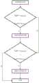
图1是本发明利用深度误差绘制图像的流程图。FIG. 1 is a flow chart of the present invention for rendering an image using depth error.
图2是本发明利用深度图像阈值对区域进行重新绘制的流程图。FIG. 2 is a flow chart of the present invention for re-rendering a region using a depth image threshold.
具体实施方式Detailed ways
下面通过实施例,并结合附图,对本发明的技术方案作进一步具体的说明。The technical solutions of the present invention will be further described in detail below through embodiments and in conjunction with the accompanying drawings.
实施例:本实施例的一种新型的图像绘制技术,如图1和图2所示,包括以下步骤:Embodiment: A novel image rendering technology of this embodiment, as shown in Figure 1 and Figure 2, includes the following steps:
(1)3D图像变换,DIBR技术中最关键的部分为3D图像变换(3DImage Wraping)它是一种针对图像像素进行变化的操作。通过三维变换将参考图像像素点映射到目标视图中,从而形成和参考图像相对应的原始目标视图。该方法本质上通过深度信息构建当前视点的三维信息,进而通过映射变换,得到其他视点的三维信息。(1) 3D image transformation, the most critical part of DIBR technology is 3D image transformation (3D Image Wraping), which is an operation that changes image pixels. The reference image pixels are mapped to the target view through three-dimensional transformation, so as to form the original target view corresponding to the reference image. This method essentially constructs the three-dimensional information of the current viewpoint through depth information, and then obtains the three-dimensional information of other viewpoints through mapping transformation.
假设图像像素p坐标为(u,v),图像平面坐标为(x,y),图像像素坐标列向量为矩阵P,相机矩阵为Camera。Suppose the image pixel p coordinate is (u, v), the image plane coordinate is (x, y), the image pixel coordinate column vector is matrix P, and the camera matrix is Camera.
M=[x y 1]TM=[xy 1]T
P=[u v 1]TP=[uv 1]T

其中f为相机的焦距,fx和fy分别为像素x方向和像素y方向的焦距。u0,v0,主点的实际位置,单位也是像素。where f is the focal length of the camera, and fx and fy are the focal lengths in the x-direction and y-direction of the pixel, respectively. u0, v0, the actual position of the main point, the unit is also pixel.
将像素坐标和图像平面坐标、相机坐标和实际三维空间的坐标进行互相联系,在像素坐标和图像坐标之间可以通过相机内参矩阵Camera得到运算关系:The pixel coordinates and the image plane coordinates, the camera coordinates and the coordinates of the actual three-dimensional space are related to each other, and the operation relationship between the pixel coordinates and the image coordinates can be obtained through the camera internal parameter matrix Camera:

然后将图像平面坐标转换为以相机为中心的相机坐标(Xc,Yc,Zc),转换关系如下Then convert the image plane coordinates to camera coordinates (Xc , Yc , Zc ) centered on the camera, and the conversion relationship is as follows

在本次实验中定义f为:In this experiment, f is defined as:

接着根据相机坐标系和普通的空间坐标系(Wx,Wy,Wz)进行进一步转换,转换关系为:Then further conversion is performed according to the camera coordinate system and the ordinary space coordinate system (Wx, Wy, Wz). The conversion relationship is:


其中px,py,pz分别表示相机在空间坐标中在x、y、z方向上的平移量。矩阵R表示相机在空间中的旋转矩阵,通常情况下,R表示为单位矩阵。向量[px py pz]T表示相机在空间中的平移量。Among them, px, py, and pz represent the translation amount of the camera in the x, y, and z directions in spatial coordinates, respectively. The matrix R represents the rotation matrix of the camera in space, and in general, R is represented as the identity matrix. The vector [px py pz ]T represents the amount of camera translation in space.
(2)利用图像之间的深度差值来划分绘制不准确区域,通过两个视点的深度值进行比较,发现当原图的深度图像和目标视图的深度图像对应位置的深度值存在一定程度的倍率差。(2) Use the depth difference between the images to divide the inaccurate area, and compare the depth values of the two viewpoints. Poor magnification.
定义两个视图深度误差为dif,像素p的深度差计算公式为:Define the depth error of the two views as dif, and the calculation formula of the depth difference of the pixel p is:
dif(p)=|D原深度图(p)-D目标深度图(p)|dif(p)=|Doriginal depth map (p)-Dtarget depth map (p)|
其中D指的是深度值,然后根据深度误差dif确定重新针对深度误差较大的区域进行绘制,确定深度误差的阈值δ,当深度误差超过阈值时,也就是dif(p)>δ时,便对区域重新进行绘制。Among them, D refers to the depth value, and then according to the depth error dif, it is determined to redraw the area with large depth error, and the threshold value δ of the depth error is determined. When the depth error exceeds the threshold value, that is, when dif(p)>δ, then Repaint the area.
根据图像深度值来划分区域并判断是否重新进行赋值,将前景部分直接进行赋值。Divide the area according to the image depth value and judge whether to re-assign, and assign the foreground part directly.
(3)设置图像的前景阈值和背景阈值来区分图像的前景区域和背景区域,然后对两区域再次进行绘制。分别设置背景阈值和前景阈值为αbackgurand和αforgurand,将两幅图像中的背景区域和前景区域做并逻辑计算,得到输出视图中的背景区域和前景区域,将所在区域的空洞部分重新进行绘制。(3) Set the foreground threshold and background threshold of the image to distinguish the foreground area and the background area of the image, and then draw the two areas again. Set the background threshold and foreground threshold as αbackgurand and αforgurand respectively , and logically calculate the background area and foreground area in the two images to obtain the background area and foreground area in the output view, and redraw the empty part of the area. .
(4)处理空洞。使用基于最小熵差的criminisi绘制方法将剩余部分空洞进行填充,将像素匹配块的选取准则调整为以最小熵差的选取方法,即匹配块的选取条件为使用熵差和选取区域像素值总和相乘之积的最小值。根据匹配块误差d(P,Q)最小的范围以及熵差值的范围,把该两种元素的差值调整到0至1之间,(4) Dealing with voids. Use the criminisi drawing method based on the minimum entropy difference to fill the remaining holes, and adjust the selection criterion of the pixel matching block to the selection method with the minimum entropy difference, that is, the selection condition of the matching block is to use the entropy difference and the sum of the pixel values of the selected area. The minimum value of the product of the multiplication. According to the minimum range of matching block error d(P, Q) and the range of entropy difference, adjust the difference between the two elements to be between 0 and 1,

H(P)=-∑p(P)log(p(P))H(P)=-∑p(P)log(p(P))
H(Q)=-∑p(Q)log(p(Q))H(Q)=-∑p(Q)log(p(Q))
其中H(P)和H(Q)分别指选取块P的匹配块Q的信息熵。Among them, H(P) and H(Q) respectively refer to the information entropy of the matching block Q of the selected block P.
采用通过空洞周边像素逐步将空洞区域减少的方法进行填充,将这些空洞进行标记,并且将这些孔洞的边缘区域进行标记,填充空洞的顺序是由空洞外侧往空洞内测逐层填充。本质是以像素值之差的最小二范数作为参考依据,选择非空洞区域的像素进行比较,最后找到对应的匹配块并将对应的中心像素填充至修复块中心像素p。然后依次修复每一块空洞边缘像素,直至孔洞填充完毕。The method of gradually reducing the hole area through the surrounding pixels of the hole is used to fill, these holes are marked, and the edge areas of these holes are marked. The order of filling the holes is from the outside of the holes to the inside of the holes. The essence is to use the least two-norm of the difference between pixel values as a reference, select pixels in non-hole areas for comparison, and finally find the corresponding matching block and fill the corresponding center pixel to the center pixel p of the repair block. Then repair each hole edge pixel in turn until the hole is filled.
填充空洞的顺序是由空洞外侧往空洞内测逐层填充,为了客观表示空洞的填充顺序,采用公式(2.1)来表达填充的顺序PThe order of filling the holes is to fill the holes layer by layer from the outside of the holes to the inside of the holes. In order to objectively represent the filling order of the holes, formula (2.1) is used to express the filling order P
P(p)=C(p)·D(p) (2.1)P(p)=C(p)·D(p) (2.1)
其中p表示边缘像素点,C(p)表示像素p的置信度,D(p)表示像素p的数据项,C(p)和D(p)的运算公式如(2.2),(2.3)所示:where p represents the edge pixel point, C(p) represents the confidence of the pixel p, D(p) represents the data item of the pixel p, and the operation formulas of C(p) and D(p) are shown in (2.2), (2.3) Show:


其中P表示以p为中心的的待修复块,count(P)表示待修复块中像素个数,q表示非空洞像素区域,
由于C(p)的取值范围在[0,1],因此在初始条件下,置信度C的初始值为Since the value range of C(p) is in [0, 1], under the initial conditions, the initial value of the confidence C is

数据项初始值均设置为-0.1,The initial value of the data item is set to -0.1,
D(p)|=-0.1 (2.5)D(p)|=-0.1 (2.5)
然后不断对空洞像素p附近的置信度和数据项按照公式(2.4)(2.5)的方式进行迭代,直到这一次边缘空洞全部填充完毕。Then, iteratively iterates the confidence and data items near the hole pixel p according to formula (2.4) and (2.5) until all the edge holes are filled this time.
Claims (9)
Translated fromChinese


Priority Applications (1)
| Application Number | Priority Date | Filing Date | Title |
|---|---|---|---|
| CN202010214373.4ACN111405265B (en) | 2020-03-24 | 2020-03-24 | Novel image drawing technology |
Applications Claiming Priority (1)
| Application Number | Priority Date | Filing Date | Title |
|---|---|---|---|
| CN202010214373.4ACN111405265B (en) | 2020-03-24 | 2020-03-24 | Novel image drawing technology |
Publications (2)
| Publication Number | Publication Date |
|---|---|
| CN111405265Atrue CN111405265A (en) | 2020-07-10 |
| CN111405265B CN111405265B (en) | 2021-09-17 |
Family
ID=71413512
Family Applications (1)
| Application Number | Title | Priority Date | Filing Date |
|---|---|---|---|
| CN202010214373.4AActiveCN111405265B (en) | 2020-03-24 | 2020-03-24 | Novel image drawing technology |
Country Status (1)
| Country | Link |
|---|---|
| CN (1) | CN111405265B (en) |
Citations (6)
| Publication number | Priority date | Publication date | Assignee | Title |
|---|---|---|---|---|
| CN101902657A (en)* | 2010-07-16 | 2010-12-01 | 浙江大学 | A method for generating virtual multi-viewpoint images based on depth map layering |
| CN102592275A (en)* | 2011-12-16 | 2012-07-18 | 天津大学 | Virtual viewpoint rendering method |
| CN103067705A (en)* | 2012-12-19 | 2013-04-24 | 宁波大学 | Preprocessing method of multi-view deep video |
| CN103996174A (en)* | 2014-05-12 | 2014-08-20 | 上海大学 | Method for performing hole repair on Kinect depth images |
| CN107018401A (en)* | 2017-05-03 | 2017-08-04 | 曲阜师范大学 | Virtual view hole-filling method based on inverse mapping |
| CN109712067A (en)* | 2018-12-03 | 2019-05-03 | 北京航空航天大学 | A virtual viewpoint rendering method based on depth image |
- 2020
- 2020-03-24CNCN202010214373.4Apatent/CN111405265B/enactiveActive
Patent Citations (6)
| Publication number | Priority date | Publication date | Assignee | Title |
|---|---|---|---|---|
| CN101902657A (en)* | 2010-07-16 | 2010-12-01 | 浙江大学 | A method for generating virtual multi-viewpoint images based on depth map layering |
| CN102592275A (en)* | 2011-12-16 | 2012-07-18 | 天津大学 | Virtual viewpoint rendering method |
| CN103067705A (en)* | 2012-12-19 | 2013-04-24 | 宁波大学 | Preprocessing method of multi-view deep video |
| CN103996174A (en)* | 2014-05-12 | 2014-08-20 | 上海大学 | Method for performing hole repair on Kinect depth images |
| CN107018401A (en)* | 2017-05-03 | 2017-08-04 | 曲阜师范大学 | Virtual view hole-filling method based on inverse mapping |
| CN109712067A (en)* | 2018-12-03 | 2019-05-03 | 北京航空航天大学 | A virtual viewpoint rendering method based on depth image |
Also Published As
| Publication number | Publication date |
|---|---|
| CN111405265B (en) | 2021-09-17 |
Similar Documents
| Publication | Publication Date | Title |
|---|---|---|
| CN111986307B (en) | 3D object reconstruction using a light grid representation | |
| US9082224B2 (en) | Systems and methods 2-D to 3-D conversion using depth access segiments to define an object | |
| KR20230007358A (en) | Multilayer Reprojection Techniques for Augmented Reality | |
| KR101310589B1 (en) | Techniques for rapid stereo reconstruction from images | |
| CN111243071A (en) | Texture rendering method, system, chip, device and medium for real-time three-dimensional human body reconstruction | |
| US20080228449A1 (en) | Systems and methods for 2-d to 3-d conversion using depth access segments to define an object | |
| US20080225045A1 (en) | Systems and methods for 2-d to 3-d image conversion using mask to model, or model to mask, conversion | |
| US20080226181A1 (en) | Systems and methods for depth peeling using stereoscopic variables during the rendering of 2-d to 3-d images | |
| US20080226160A1 (en) | Systems and methods for filling light in frames during 2-d to 3-d image conversion | |
| US20080226128A1 (en) | System and method for using feature tracking techniques for the generation of masks in the conversion of two-dimensional images to three-dimensional images | |
| US9367943B2 (en) | Seamless fracture in a production pipeline | |
| CN114049464B (en) | Reconstruction method and device of three-dimensional model | |
| CN104822059B (en) | A kind of virtual visual point synthesizing method accelerated based on GPU | |
| CN112508821B (en) | A Stereo Vision Virtual Image Hole Filling Method Based on Oriented Regression Loss Function | |
| CN109410133B (en) | Face texture repairing method based on 3DMM | |
| CN104751508B (en) | The full-automatic of new view is quickly generated and complementing method in the making of 3D three-dimensional films | |
| CN119648925B (en) | Efficient 3D Gaussian scene reconstruction method based on multi-mode depth distribution supervision | |
| JP2023552538A (en) | Image processing methods and devices, electronic devices, storage media, and computer programs | |
| CN116310111A (en) | Indoor scene three-dimensional reconstruction method based on pseudo-plane constraint | |
| CN116363290A (en) | Texture map generation method for large-scale scene three-dimensional reconstruction | |
| CN116228986A (en) | Indoor scene illumination estimation method based on local-global completion strategy | |
| CN117541755A (en) | RGB-D three-dimensional reconstruction-based rigid object virtual-real shielding method | |
| CN113450274A (en) | Self-adaptive viewpoint fusion method and system based on deep learning | |
| CN118279485A (en) | Face reconstruction method based on deep learning and multi-eye stereoscopic vision | |
| CN114742954B (en) | A method for constructing large-scale diverse face image and model data pairs |
Legal Events
| Date | Code | Title | Description |
|---|---|---|---|
| PB01 | Publication | ||
| PB01 | Publication | ||
| SE01 | Entry into force of request for substantive examination | ||
| SE01 | Entry into force of request for substantive examination | ||
| GR01 | Patent grant | ||
| GR01 | Patent grant | ||
| TR01 | Transfer of patent right | ||
| TR01 | Transfer of patent right | Effective date of registration:20231020 Address after:Room 701, Building 5, No. 643 Shuangliu, Xihu District, Hangzhou City, Zhejiang Province, 310000 Patentee after:HANGZHOU EYECLOUD TECHNOLOGY Co.,Ltd. Address before:310018 Xiasha Higher Education Zone, Hangzhou, Zhejiang, Jianggan District Patentee before:HANGZHOU DIANZI University |